

Page 1
Building Networks for People
Network
Security Firewall
This Quick Guide will guide you through the installation Process. You are
only moments away from using your new D-Link Network Security Product
DFL-1600
Page 2

DFL-1600 Quick Installation Guide
1.Before You Begin
1.1 Check Your Package Contents....................................................................1
2.Indentifying Components
2.1 Front View................................................................................................2
2.2 LCD Panel.................................................................................................3
2.3 LED Indicators...........................................................................................5
2.4 Default interface attribute definition..........................................................5
3.Connecting the DFL-1600
3.1 Setting up Firewall to your Network........................................................6
4.Configure DFL-1600
4.1 Configure your Computer ’s IP..................................................................7
4.2 Using the Setup Wizard.............................................................................8
5.Appendix
5.1 How to Configure Static IP Manually on Microsoft Windows XP..............17
5.2 How to Configure Static IP Manually on Apple MAC OS X...........................18
6.Statement
Page 3
DFL-1600
Before You Begin
1.1 Check Your Package Contents
Your NetDefend Network Security Firewall package should
contain all the items listed below. If any of these items is found
damaged or missing in your package, report it to your reseller
immediately for replacement.
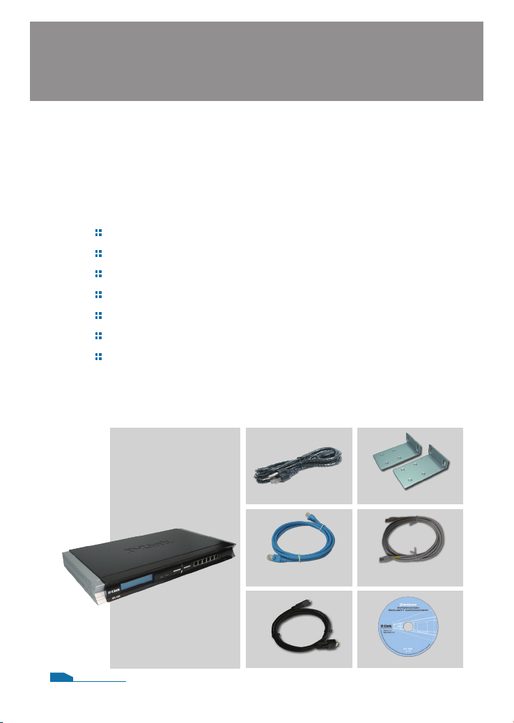
One (1) DFL-1600 NetDefend™ Network Security Firewall
One (1) Power Cord
One (1) Console Cable (RS-232 cable)
One (1) Ethernet (CAT5 UTP/Straight Through) Cable
One (1) Ethernet (CAT5 UTP/Cross-over) Cable
One (1) CD-ROM (containing QIG/Manual )
Two (2) Rack Mount Brackets
1
Power Cord
Ethernet Cable
(Straight-Through)
DFL-1600
01
Console Cable CD-ROM
Rack Mount Brackets
Ethernet Cable
(Cross-over)
Page 4
Identifying Components
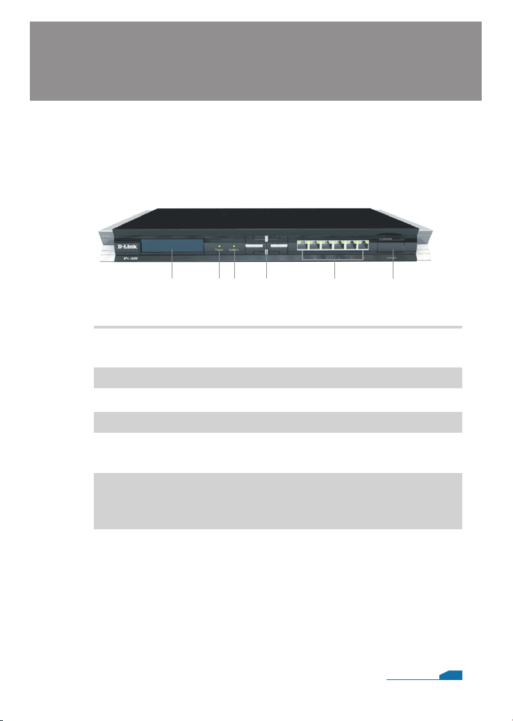
The following illustrates the front panel of the DFL-1600 and
explains the front panel’s key components:
2.1 Front View
2
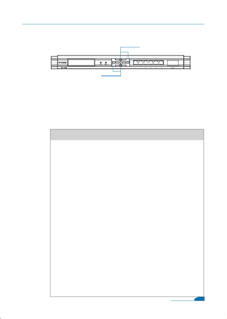
1 2 4 5 6
1. LCD Panel
2. Power LED
3. System LED
4. Keypad
5. Ethernet ports
6. Console Port
3
Used to display operation messages and various status of
the DFL-1600. See the following section for details.
Power indication of the DFL-1600.
System status indication of the DFL-1600.
Operation keys used in conjunction with the LCD panel.
Connect to Ethernet cables that connect to broadband
modems and network switches.
Connects to RS-232 console cable that connects to PC.
The console port is hidden behind a protection coverlid that
can be opened by pulling down the lid.
02
Page 5
DFL-1600 Quick Installation Guide
2.2 LCD Panel and Keypad
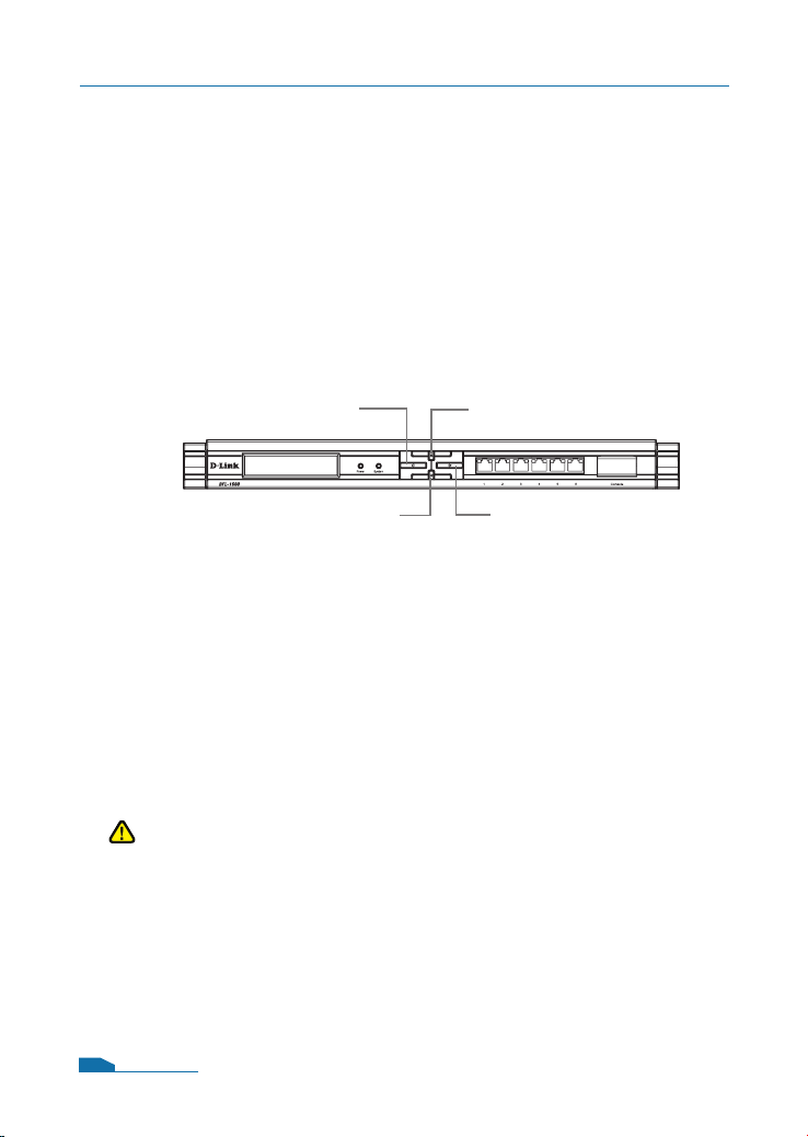
When you turn on the power of the DFL-1600, the LCD panel
will display the following message: “Press Keypad to enter
setup” and press any key on the keypad to enter the startup
menu. If after ve seconds, you do not press any key on the
keypad, the DFL-1600 will automatically start the system.
2.2.1 Startup Menu
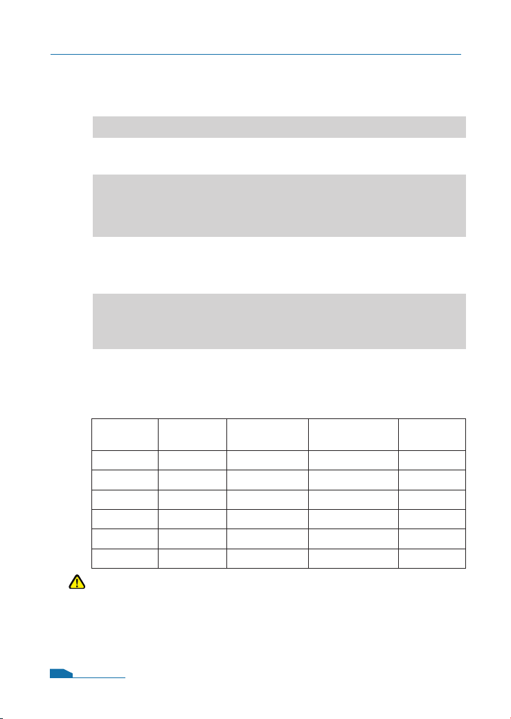
Back Button
Conrm Button
Keypad buttons denition in Startup Menu
Not Used
Next Button
If you press any key within ve seconds after power-on, the
LCD will display two options:
1. Start Firewall: If you select this option, the system will start,
using the conguration saved inside the device.
2. Reset Firewall: If you select this option, the system will start,
using the factory default conguration.
Note:
If you select “Reset Firewall” and conrm this option, all previous
congurations that you saved in this device will be lost forever.
03
Page 6
DFL-1600 Quick Installation Guide
2.2.2 Device Status and Information
Next Button
Back Button
Keypad buttons denition in Status Information
After the DFL-1600 has completed its system startup, the LCD
panel is ready to display the status and information of this
device. You can use the keypad to select a desired display
option. The following shows status and information that can be
displayed on the LCD panel.
Item
Model name:
System Status:
CPU Load:
Connections:
Total BPS:
Total PPS:
Date:
Time:
Uptime:
Mem:
IDS Sigs:
WAN1:
WAN2:
DMZ:
LAN1:
LAN2:
LAN3:
Core Version:
Description
Display the device model name.
Display system working status.
It will show the CPU utilization and
concurrent session
Concurrent trafc statistics per second.
Concurrent packets statistics per second.
Device current date.
Device current time.
Device boot up time.
System memory utilization.
It will display IDS signature information.
Display each interface IP address
Display rewall rmware version.
04
Page 7
DFL-1600 Quick Installation Guide
2.3 LED Indicators
LED
Power
System
Phone Jack LED
light (right)
Phone Jack LED
light (left)
Status
Solid green
Light off
Solid green
Light off
Blinking green
Light off
Solid Green
Blinking Green
Light off
Solid green
Solid orange
Description
Color
The device is powered on.
Green
The device is powered off.
System is operating properly.
Green
The device is not working.
System is defective, such rmware
upgrade fail.
No link
Green
Link present
Port is sending or receiving data.
Port is operating at 10Mbps.
Green/
Port is operating at 100Mbps.
Orange
Port is operating at 1000Mbps.
2.4 Default Interface Attribute Definition
Wording on
Front plate
1 WAN1
2 WAN2 Static IP 192.168.120.254/24 Disable
3 DMZ Static IP 172.17.100.254/24 Disable
4 LAN1 Static IP 192.168.1.1/24 Disable
5 LAN2 Static IP 192.168.2.1/24 Disable
6 LAN3 Static IP 192.168.3.1/24 Disable
Default name
in rewall
Default interface
type denition
DHCP client N/A Enabled
Default interface
IP Address
DHCP Status
Default
Note:
NetDefendOS only allows Web GUI access from LAN 1 port by
default for security consideration. Please refer to user manual for
more detail about how to change this conguration.
05
Page 8

Connecting the DFL-1600
3.1 Connecting Firewall to Your Network
A. First, connect the power cord to the receptor at the back panel of
the DFL-1600 and then plug the other end of the power cord to a
wall outlet or power strip. Then powered on the DFL-1600 using
the on/off switch. Now the Power LED will turn ON to indicate
proper operation. After the power LED turns on, you need to wait
1-2 minutes for the DFL-1600 to boot up completely.
B. Connect an Ethernet cable from the DFL-1600 to your Cable/
DSL modem. If the Cable/DSL modem is powered on, wait for
the WAN1 LED on the DFL-1600 to light up to show a proper
connection. Otherwise, turn off your Cable/DSL modem, connect
the Ethernet cable from the DFL-1600 to your Cable/DSL
modem, and turn on the Cable/DSL modem. Some Cable/DSL
modems may not have an on/off switch and will require you to
unplug the power adapter.
Note:
The default management IP address of the DFL-1600 is
192.168.1.1. If you have are using a router that uses DHCP,
there may be a conict if the router uses the same IP address as
the DFL-1600. If this is the case, either disconnect the DFL-1600
from the router and change the management IP address of the
DFL-1600, or change the DHCP settings on your router.
3
C. Insert an Ethernet cable to the LAN1 port on the front panel of
the DFL-1600 and connect it to a port on your network hub or
switch. The LED light above the Ethernet port on the DFL-1600
will illuminate to indicate proper connection
D. Connecting the computer that you will use to congure the
DFL-1600 to the network hub or switch.
06
Page 9
Configure DFL-1600
4
4.1 Configure Your Computer’s IP Address
Make sure that the network adapter in your computer is
congured to use a static IP address with 192.168.1.1
as default gateway and 255.255.255.0 as netmask.
Instructions on how to congure the network adapter can
be found in the appendix.
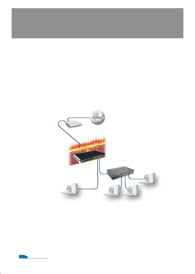
When you have completed the steps in this Quick Installation
Guide, your connected network should look similar to this:
Cable/DSL Modem
DFL-1600
Switch
Internal
DMZ
Network
(optional)
Network
Computer1 Computer2
07
Page 10
DFL-1600 Quick Installation Guide
4.2 Using the Setup Wizard
The DFL-1600 provides Web based conguration. You can congure
your DFL-1600 through Internet Explorer 6 and later or Firefox 1.0 and
later browser in MS Windows, Macintosh or UNIX based platforms.
Activate your browser, and ensure your built-in Pop-Up Blocker has been
disabled, so that the Pop-Up Blocker will not block the Startup Wizard
while you initiate the NetDefend Firewall for the rst time.
Additionally, in order to reduce the impact of Pop-Up Blocker, a userfriendly mechanism has beem implemented in NetDefend Firewalls. A
"Startup Wizard" button is shown on the toolbar since rmware v2.20.
This button is available on the WebGUI while the appliance is initiated
with Conguration Version 1. Once you complete conguration and
save/activate the setting, the Startup Wizard button will be removed
automatically from the toolbar while you login WebGUI next time.
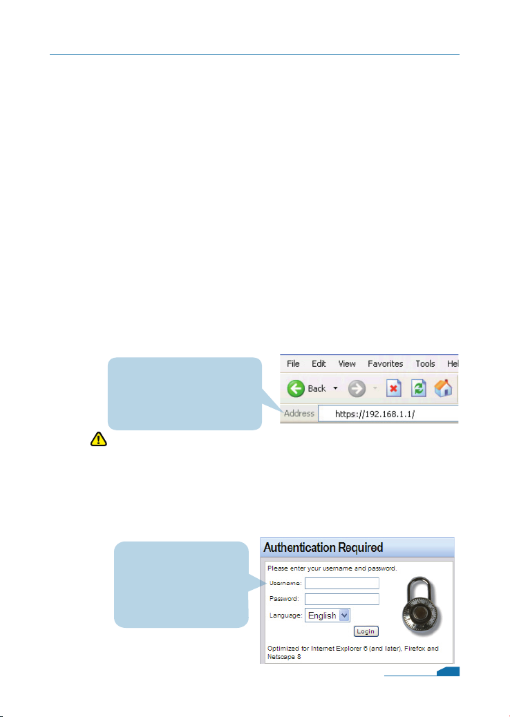
Now, let's start on WebGUI login, type the IP address of the DFL-1600,
e.g. https://192.168.1.1, in the Location (for Netscape) or Address (for
IE) eld and press "Enter".
Open your Web browser and
type https://192.168.1.1 /
into the URL address box.
Then press the Enter or
Return key.
Note:
DFL-1600 allows either HTTP or a secure HTTPS connection
from any management host. However, for security reason, by
default only a secure HTTPS connection is allowed.
Log on to the DFL-1600 web interface.
To start using the DFL-1600 web interface you need to log on
using the default username and password.
Type the default
Username/Password
Username: admin
Pasword: admin
and click Login
08
Page 11
DFL-1600 Quick Installation Guide
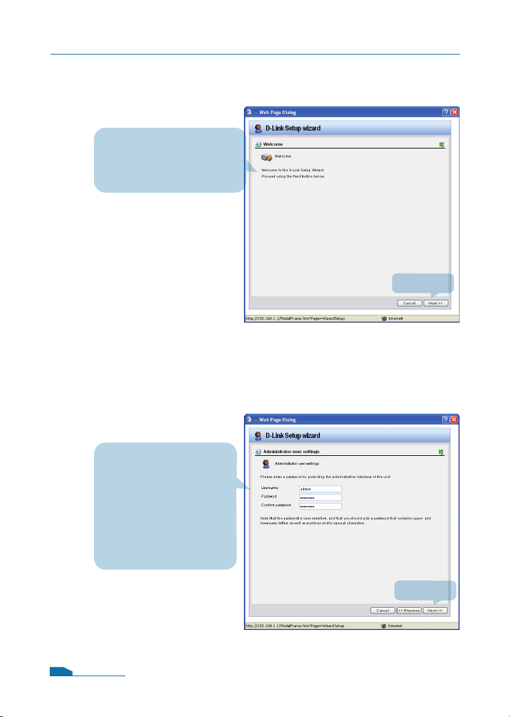
Step1 - Welcome to the DFL-1600 setup wizard!
This wizard will guide
you through the setup of
your DFL-1600
Step2 - Set up rewall administrator password
Click Next
First Enter the
username that you want
to use for the admin
account.
Enter the password
that you want to use
for the admin account.
Click Next
09
Page 12
DFL-1600 Quick Installation Guide
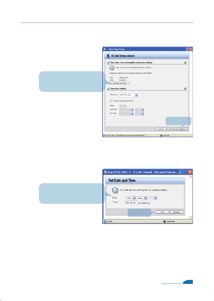
Step 3 - Set up time and date
Click Set time and date
button for setting device
Select the appropriate date
Enter the appropriate time
2
Click Next
Click OK
10
Page 13
DFL-1600 Quick Installation Guide
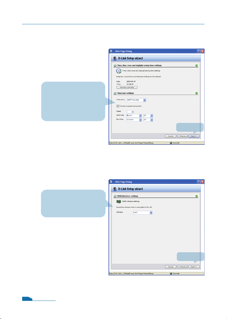
Step 4 - Set up timezone
Select the appropriate
timezone.
Enter the appropriate
dayligt saving time
settings.
Step 5 - Select WAN interface
Click Next
Select the WAN
interface that you want
to use.
Click Next
11
Page 14
DFL-1600 Quick Installation Guide
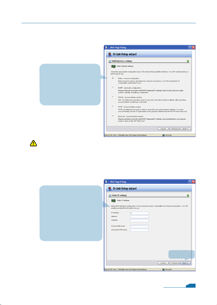
Step 6 - Congure WAN interface
Select the appropriate
conguration for the
WAN interface,
Click Next and
continue to step 7.1
further down.
Note:
If you are unsure of which setting to select, please contact your
Internet Service Provider.
Step 7.1 - WAN Interface Type is Static IP
If you selected Static IP
you have to ll out the
IP address information
provided to you by
your ISP. You will need
to complete all the
required elds except for
Secondary DNS Server.
Click Next
12
Page 15
DFL-1600 Quick Installation Guide
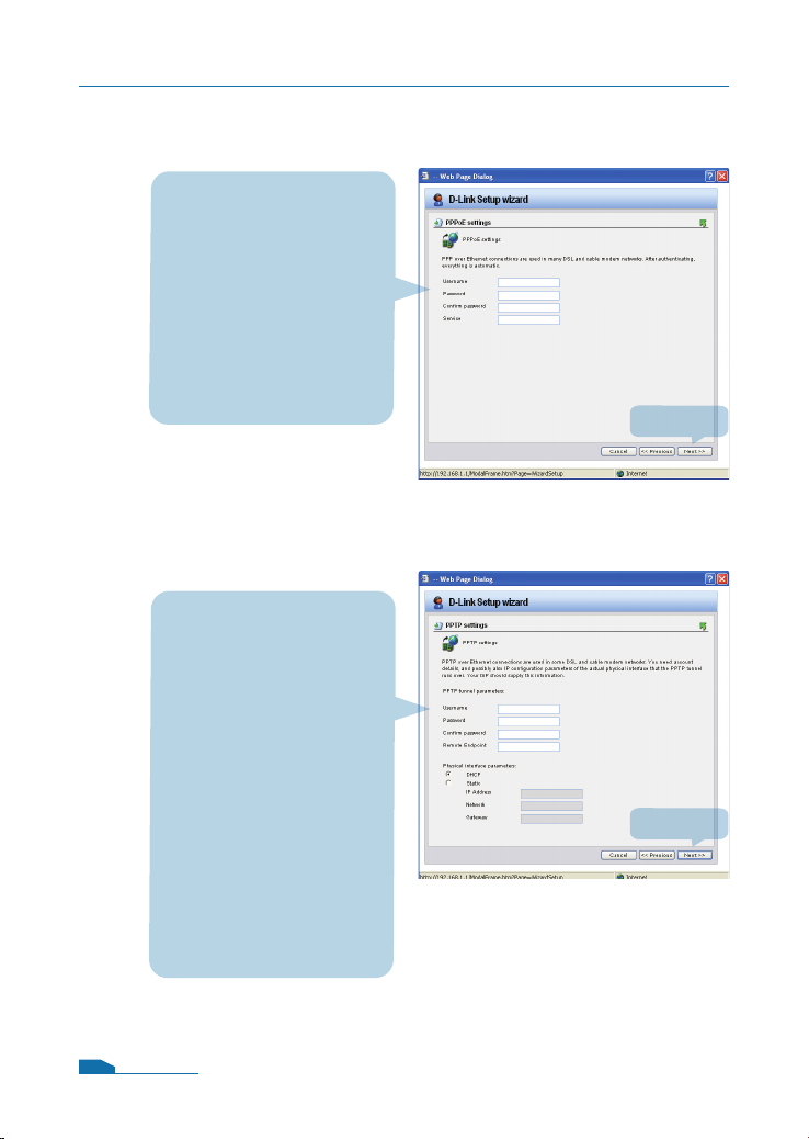
Step 7.2 - WAN Interface Type is PPPoE
If you selected PPPoE
(Point-to-Point Protocol
over Ethernet) you will
have to ll out the user
name and password
provided to you by your
ISP. The PPPoE Service
Name eld should be left
blank unless your ISP
informs you otherwise.
Step 7.3 - WAN Interface Type is PPTP
Enter Username,
Password and the
PPTP Server IP address
provided by your ISP.
DHCP:If your ISProvider
is using DHCP you
should select the DHCP
radio button.
Static IP:If your Internet
Service Provider is using
Static IP you should
select the Static IP
radio button and enter
IP Address, choose a
Subnet Mask and enter
the Gateway IP address.
Click Next
Click Next
13
Page 16
DFL-1600 Quick Installation Guide
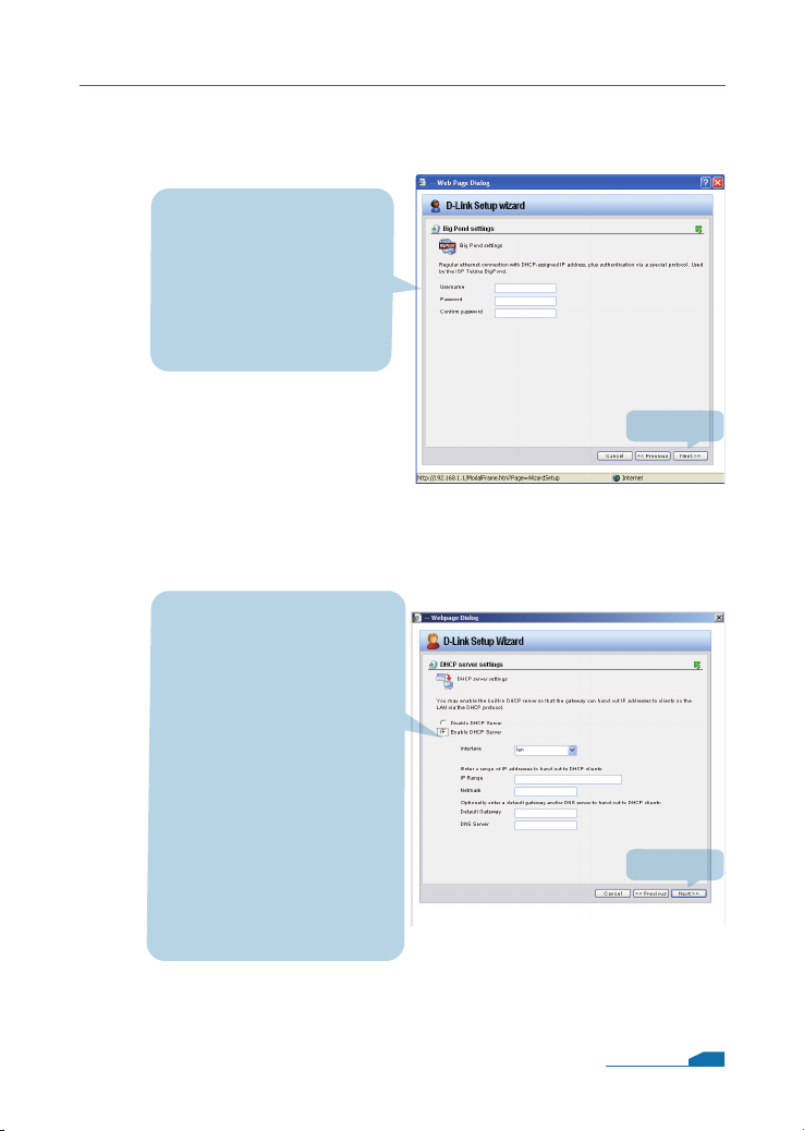
Step 7.4 - WAN Interface Type is Big Pond
If you selected Big Pond
you will have to ll out the
user name and password
provided to you by your
ISP.
Click Next and continue
to step 8.
Step 8 - Set up built-in DHCP server
If you want to use the
built-in DHCP Server in
the DFL-1600, choose
Enable DHCP Server
in this screen. You then
need to specify a range
of IP addresses to hand
out to the DHCP clients.
This range is entered in
the format “Start IP - Stop
IP” i.e. 192.168.0.100 -
192.168.0.200. If you don’t
want to use the built-in
DHCP Server or congure
it later, choose Disable
DHCP Server.
Click Next
Click Next
14
Page 17
DFL-1600 Quick Installation Guide
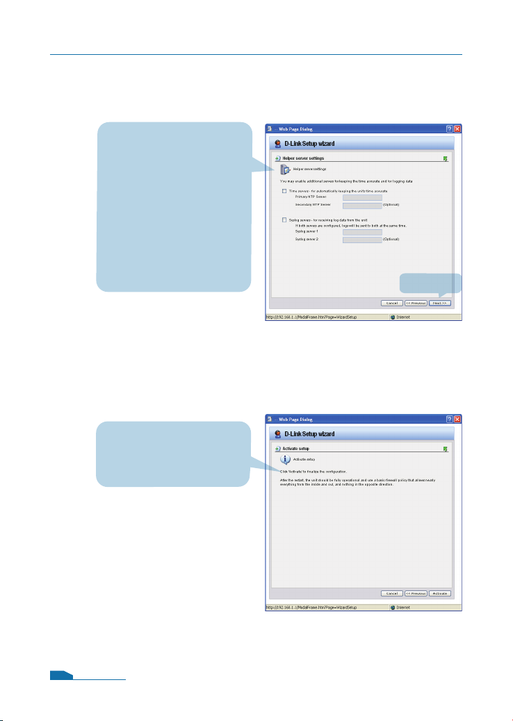
Step 9 - Congure helper servers
NTP Servers
If enabled, specify which
NTP Servers that should
be used to syncronize
the rewall time
Syslog Servers
If enabled, specify
where the rewall should
log, you can specify up
to two Syslog recievers
Step10 - Setup Wizard Complete
Click Activate to
complete your
conguration.
Click Next
15
Page 18
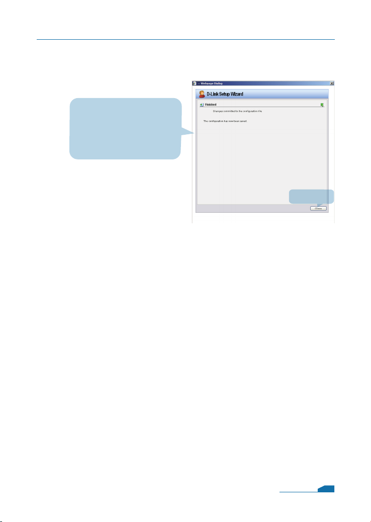
Step 11 - Conrmation
Conrm the changes
committed to the
conguration le and it
has been saved now.
DFL-1600 Quick Installation Guide
Click Close
16
Page 19
Appendix
To connect to the DFL-1600 Network Security Firewall, make
sure the network adapter in your computer is congured
properly. Here is how to congure the network adapter
manually to the correct IP-address.
5
5.1 How to configure Static IP Manually on
Microsoft Windows XP
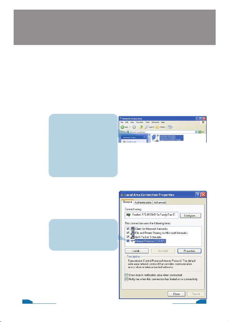
Go to Start > right click
on My Network Places >
select Properties >
Right-click on the
Network Connection
of the Ethernet adapter
connecting to the
DFL-1600 and select
Properties.
Click Internet Protocol
(TCP/IP)
Click Properties
17
16
Page 20
DFL-1600 Quick Installation Guide
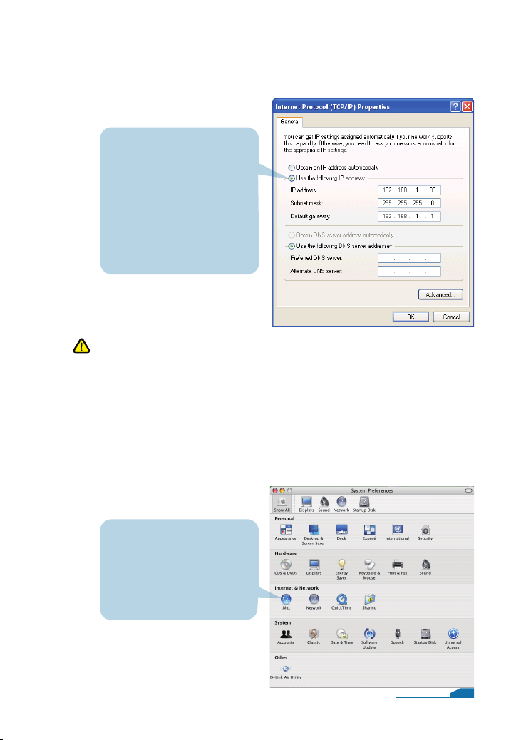
Select Use the
following IP address
Set IP address to
192.168.1.30,
Subnet mask to
255.255.255.0
and Default gateway to
192.168.1.1
Click OK
Note:
Except for 192.168.1.1, you could set your PC with any IP
addresses that same as the 192.168.1.0/ 255.255.255.0 subnet.
5.2 How to Configure Static IP Manually on
Apple Mac OS X
Go to the Apple Menu
Click on Network
and Select System
Preferences
Click on Network
18
Page 21
DFL-1600 Quick Installation Guide
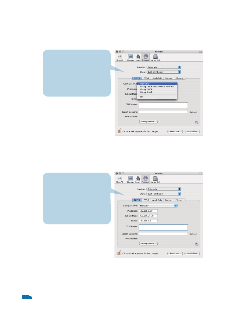
Select Built-in Ethernet
in the show pull down
menu
Select Manually in the
Congure pull down
menu
Set IP Address to
192.168.1.30,
Subnet Mask to
255.255.255.0
and Router to
192.168.1.1.
Click on Apply Now
19
Page 22

STATEMENT
EMI Statement
FCC Warning
This equipment has been tested and found to comply with the
limits for a Class A digital device, pursuant to Part 15 of the FCC
Rules. These limits are designed to provide reasonable protection
against harmful interference when the equipment is operated in
a commercial environment. This equipment generates, uses, and
can radiate radio frequency energy and, if not installed and used
in accordance with this manual, may cause harmful interference to
radio communications. Operation of this equipment in a residential
area is likely to cause harmful interference in which case the user
will be required to correct the interference at his own expense.
CE Mark Warning
This is a Class A product. In a domestic environment, this product
may cause radio interference in which case the user may be required
to take adequate measures.
Warnung!
Dies ist ein Produkt der Klasse A. Im Wohnbereich kann dieses
Produkt Funkstoerungen verursachen. In diesem Fall kann
vom Benutzer verlangt werden, angemessene Massnahmen zu
ergreifen.
6
Precaución!
Este es un producto de Clase A. En un entorno doméstico, puede
causar interferencias de radio, en cuyo case, puede requerirse al
usuario para que adopte las medidas adecuadas.
Attention!
Ceci est un produit de classe A. Dans un environnement domestique,
ce produit pourrait causer des interférences radio, auquel cas
l`utilisateur devrait prendre les mesures adéquates.
20
Page 23
VCCI Warning
DFL-1600 Quick Installation Guide
Attenzione!
Il presente prodotto appartiene alla classe A. Se utilizzato in ambiente
domestico il prodotto può causare interferenze radio, nel cui caso è
possibile che l`utente debba assumere provvedimenti adeguati.
VCCI Warning
BSMI Warning
警告使用表
這是甲類的資訊產品,在居住的環境中使用時,可能會造成射頻干擾,在這
種情況下使用者會被要求採取某些適當的對策。
21
 Loading...