

D-Link DES-3810 Hardware Installation Manual

Information in this document is subject to change without notice. Reproduction in any manner whatsoever, without the written permissi on of D-Link
Corporation, is strictly forbidden.
Trademarks used in this text: D-Link and the D-LINK logo are trademarks of D-Link Corporation; Microsoft and Windows are registered trademarks
of Microsoft Corporation.
Other trademarks and trade names may be used in this document to refer to either the entities claiming the marks and names or their products. DLink Corporation disclaims any proprietary interest in trademarks and trade names other than its own.
© 2010 D-Link Corporation. All rights reserved.
Novemeber 2010 P/N 651ES3810025G
FCC Warning
This equipment has been tested and found to comply with the limits for a Class A digital device, pursuant to Part 15 of
the FCC Rules. These limits are designed to provide reasonable protection against harmful interference when the
equipment is operated in a commercial environment. This equipment generates, uses, and can radiate radio
frequency energy and, if not installed and used in accordance with this manual, may cause harmful interference to
radio communications. Operation of this equipment in a residential area is likely to cause harmful interference in
which case the user will be required to correct the interference at his own expense.
CE Mark Warning
This is a Class A product. In a domestic environment, this product may cause radio interference in which case the
user may be required to take adequate measures.
Warnung!
Dies ist ein Produkt der Klasse A. Im Wohnbereich kann dieses Produkt Funkstoerungen verursachen. In diesem Fall
kann vom Benutzer verlangt werden, angemessene Massnahmen zu ergreifen.
Precaución!
Este es un producto de Clase A. En un entorno doméstico, puede causar interferencias de radio, en cuyo case, puede
requerirse al usuario para que adopte las medidas adecuadas.
Attention!
Ceci est un produit de classe A. Dans un environnement domestique, ce produit pourrait causer des interférences
radio, auquel cas l`utilisateur devrait prendre les mesures adéquates.
Attenzione!
Il presente prodotto appartiene alla classe A. Se utilizzato in ambiente domestico il prodotto può causare interferenze
radio, nel cui caso è possibile che l`utente debba assumere provvedimenti adeguati.
VCCI Warning
この装置は、クラス A 情報技術装置です。この装置を家庭環境で使用すると電波妨害を引き起こすことがあります。
この場合には使用者が適切な対策を講ずるよう要求されることがあります。 VCCI-A

xStack® DES-3810 Series Layer 3 Ethernet Managed Switch Hardware Insta llati on G uide
iii
Table of Contents
Intended Readers ........................................................................................................................................................... v
Typographical Conventions ............................................................................................................................................ v
Notes, Notices, and Cautions ......................................................................................................................................... v
Safety Instructions ......................................................................................................................................................... vi
Safety Cautions ........................................................................................................................................................... vi
General Precautions for Rack-Mountable Prod uct s ...................................................................................................... vii
Protecting Against Electrostatic Discharge .................................................................................................................. viii
Chapter 1 Introduction ................................................................................................................................................ 9
Switch Description .......................................................................................................................................................... 9
Features ........................................................................................................................................................................ 10
Ports ............................................................................................................................................................................. 11
Front-Panel Components ........................................................................................................................................... 11
LED Indicators ........................................................................................................................................................... 12
Rear Panel Description .............................................................................................................................................. 13
Side Panel Description ............................................................................................................................................... 13
Chapter 2 Installation ................................................................................................................................................ 14
Package Contents ........................................................................................................................................................ 14
Installation Guidelines .................................................................................................................................................. 14
Installing the Switch without a Rack .......................................................................................................................... 15
Attaching Brackets to a Switch for Rack Mounting .................................................................................................... 15
Mounting the Switch in a Standard 19" Rack ............................................................................................................ 16
Power On ...................................................................................................................................................................... 16
Power Failure ............................................................................................................................................................. 16
Installing SFP Ports ...................................................................................................................................................... 17
Connect to RPS ............................................................................................................................................................ 18
External Redundant Power System ............................................................................................................................. 19
DPS-900 ..................................................................................................................................................................... 19
DPS-800 ..................................................................................................................................................................... 20
Chapter 3 Connecting the Switch ............................................................................................................................ 22
Switch to End Node ...................................................................................................................................................... 22
Switch to Switch ........................................................................................................................................................... 22
Connecting To Network Backbone or Server ............................................................................................................... 23
Chapter 4 Introduction to Switch Management ..................................................................................................... 24
Management Options ................................................................................................................................................... 24
Connecting the Console Port........................................................................................................................................ 24
First Time Connecting to the Switch ............................................................................................................................. 25
Connecting to the Management Port ............................................................................................................................ 26
Password Protection ..................................................................................................................................................... 26
IP Address Assignment ................................................................................................................................................ 27
SNMP Settings ............................................................................................................................................................. 27
Traps .......................................................................................................................................................................... 28
Management Information Base (MIB) ........................................................................................................................ 28
Chapter 5 Web-based Switch Configuration .......................................................................................................... 29
Introduction ................................................................................................................................................................... 29
Logging onto the Web Manager ................................................................................................................................... 29
Web-based User Interface ............................................................................................................................................ 30
Areas of the User Interface ........................................................................................................................................ 30
Web Pages ................................................................................................................................................................... 30

xStack® DES-3810 Series Layer 3 Ethernet Managed Switch Hardware Insta llati on G uide
iv
Appendix Section .......................................................................................................................................................... 31
Appendix A – Technical Specifications ........................................................................................................................ 31
General ...................................................................................................................................................................... 31
Physical and Environmental....................................................................................................................................... 31
Performance............................................................................................................................................................... 32
LED Indicators ........................................................................................................................................................... 32
Port Functions ............................................................................................................................................................ 33
Appendix B – Cables and Connectors ......................................................................................................................... 35
Ethernet Cable ........................................................................................................................................................... 35
Console Cable ........................................................................................................................................................... 35
Redundant Power Supply (RPS) Cable ..................................................................................................................... 36
Warranties & Technical Support ................................................................................................................................ 38
xStack® DES-3810 Series Layer 3 Ethernet Managed Switch Hardware Insta llati on G uide
v
Intended Readers
Typographical Conventions
Notes, Notices, and Cautions
Safety Instructions
The DES-3810-28 User Guide contains information for setup and management of the Switch. This manual is intended
for network managers familiar with network management concepts and terminology.
Typographical Conventions
Convention Description
[ ] In a command line, square brackets indicate an optional entry. For example: [copy
filename] means that optionally you can type copy followed by the name of the file. Do
not type the brackets.
Bold font Indicates a button, a toolbar icon, menu, or menu item. For example: Open the File
menu and choose Cancel. Used for emphasis. May also indicate system messages or
prompts appearing on screen. For example: You have mail. Bold font is also used to
represent filenames, program names and commands. For example: use the copy
command.
Boldface Typewriter
Font
Indicates commands and responses to prompts that must be typed exactly as printed in
the manual.
Initial capital letter Indicates a window name. Names of keys on the keyboard have initial capitals. For
example: Click Enter.
Italics
Indicates a window name or a field. Also can indicate a variables or parameter that is
replaced with an appropriate word or string. For example: type filename means that the
actual filename should be typed instead of the word shown in italic.
Menu Name > Menu
Option
Menu Name > Menu Option Indicates the menu structure. Device > Port > Port
Properties means the Port Properties menu option under the Port menu option that is
located under the Device menu.
Table 1. Typographical Conventions
Notes, Notices, and Cautions
A NOTE indicates important information that helps make better use of the device.
A NOTICE indicates either potential damage to hardware or loss of data and tells how to avoid the
problem.
A CAUTION indicates a potential for property damage, personal injury, or death.

xStack® DES-3810 Series Layer 3 Ethernet Managed Switch Hardware Insta llati on G uide
vi
Safety Instructions
Use the following safety guidelines to ensure your own personal safety and to help protect your system from potential
damage. Throughout this safety section, the caution icon (
) is used to indicate cautions and precautions that need
to be reviewed and followed.
Safety Cautions
To reduce the risk of bodily injury, electrical shock, fire, and damage to the equipment observe the following
precautions:
• Observe and follow service markings.
o Do not service any product except as explained in the system documentation.
o Opening or removing covers that are marked with the triangular symbol with a lightning bolt may
expose the user to electrical shock.
o Only a trained service technician should service components inside these compartments.
• If any of the following conditions occur, unplug the product from the electrical outlet and replace the part or
contact your trained service provider:
o Damage to the power cable, extension cable, or plug.
o An object has fallen into the product.
o The product has been exposed to water.
o The product has been dropped or damaged.
o The product does not operate correctly when the operating instructions are correctly followed.
• Keep your system away from radiators and heat sources. Also, do not block cooling vents.
• Do not spill food or liquids on system components, and never operate the product in a wet environment. If the
system gets wet, see the appropriate section in the troubleshooting guide or contact your trained service
provider.
• Do not push any objects into the openings of the system. Doing so can cause fire or electric shock by shorting
out interior components.
• Use the product only with approved equipment.
• Allow the product to cool before removing covers or touching internal components.
• Operate the product only from the type of external power source indicated on the electrical ratings label. If
unsure of the type of power source required, consult your service provider or local power company.
• To help avoid damaging the system, be sure the voltage selection switch (if provided) on the power supply is
set to match the power available at the Switch’s location:
o 115 volts (V)/60 hertz (Hz) in most of North and South America and some Far Eastern countries such
as South Korea and Taiwan
o 100 V/50 Hz in eastern Japan and 100 V/60 Hz in western Japan
o 230 V/50 Hz in most of Europe, the Middle East, and the Far East
• Also, be sure that attached devices are electrically rated to operate with the power available in your location.
• Use only approved power cable(s). If you have not been provided with a power cable for your system or for any
AC-powered option intended for your system, purchase a power cable that is approved for use in your country.
The power cable must be rated for the product and for the voltage and current marked on the product's
electrical ratings label. The voltage and current rating of the cable should be greater than the ratings marked
on the product.
• To help prevent electric shock, plug the system and peripheral power cables into properly grounded electrical
outlets. These cables are equipped with three-prong plugs to help ensure proper grounding. Do not use
adapter plugs or remove the grounding prong from a cable. If using an extension cable is necessary, use a 3wire cable with properly grounded plugs.
• Observe extension cable and power strip ratings. Make sure that the total ampere rating of all products
plugged into the extension cable or power strip does not exceed 80 percent of the ampere ratings limit for the
extension cable or power strip.
• To help protect the system from sudden, transient increases and decreases in electrical power, use a surge
suppressor, line conditioner, or uninterruptible power supply (UPS).

xStack® DES-3810 Series Layer 3 Ethernet Managed Switch Hardware Insta llati on G uide
vii
• Position system cables and power cables carefully; route cables so that they cannot be stepped on or tripped
over. Be sure that nothing rests on any cables.
• Do not modify power cables or plugs. Consult a licensed electrician or your power company for site
modifications. Always follow your local/national wiring rules.
• When connecting or disconnecting power to hot-pluggable power supplies, if offered with your system, observe
the following guidelines:
o Install the power supply before connecting the power cable to the power supply.
o Unplug the power cable before removing the power supply.
o If the system has multiple sources of power, disconnect power from the system by unplugging all
power cables from the power supplies.
• Move products with care; ensure that all casters and/or stabilizers are firmly connected to the system. Avoid
sudden stops and uneven surfaces.
General Precautions for Rack-Mountable Products
Observe the following precautions for rack stability and safety. Also, refer to the rack installation documentation
accompanying the system and the rack for specific caution statements and procedures.
• Systems are considered to be components in a rack. Thus, "component" refers to any system as well as to
various peripherals or supporting hardware.
CAUTION: Installing systems in a rack without the front and side stabilizers installed could cause the rack
to tip over, potentially resulting in bodily injury under certain circumstances. Therefore, always install the
stabilizers before installing components in the rack. After installing system/components in a rack, never
pull more than one component out of the rack on its slide assemblies at one time. The weight of more than
one extended component could cause the rack to tip over and may result in serious injury.
• Before working on the rack, make sure that the stabilizers are secured to the rack, extended to the floor, and
that the full weight of the rack rests on the floor. Install front and side stabilizers on a single rack or front
stabilizers for joined multiple racks before working on the rack.
• Always load the rack from the bottom up, and load the heaviest item in the rack first.
• Make sure that the rack is level and stable before extending a component from the rack.
• Use caution when pressing the component rail release latches and sliding a component into or out of a rack;
the slide rails can pinch your fingers.
• After a component is inserted into the rack, carefully extend the rail into a locking position, and then slide the
component into the rack.
• Do not overload the AC supply branch circuit that provides power to the rack. The total rack load should not
exceed 80 percent of the branch circuit rating.
• Ensure that proper airflow is provided to components in the rack.
• Do not step on or stand on any component when servicing other components in a rack.
NOTE: A qualified electrician must perform all connections to DC power and to safety grounds. All
electrical wiring must comply with applicable local or national codes and practices.
CAUTION: Never defeat the ground conductor or operate the equipment in the absence of a suitably
installed ground conductor. Contact the appropriate electrical inspection authority or an electrician if
uncertain that suitable grounding is available.
CAUTION: The system chassis must be positively grounded to the rack cabinet frame. Do not attempt to
connect power to the system until grounding cables are connected. Completed power and safety ground
wiring must be inspected by a qualified electr ica l inspector. An energy hazard will exist if the safety

xStack® DES-3810 Series Layer 3 Ethernet Managed Switch Hardware Insta llati on G uide
viii
ground cable is omitted or disconnected.
Protecting Against Electrostatic Discharge
Static electricity can harm delicate components inside the system. To prevent static damage, discharge static
electricity from your body before touching any of the electronic components, such as the microprocessor. This can be
done by periodically touching an unpainted metal surface on the chassis.
The following steps can also be taken prevent damage from electrostatic discharge (ESD):
1. When unpacking a static-sensitive component from its shipping carton, do not remove the component from
the antistatic packing material until ready to install the component in the system. Just before unwrapping the
antistatic packaging, be sure to discharge static electricity from your body.
2. When transporting a sensitive component, first place it in an antistatic container or packaging.
3. Handle all sensitive components in a static-safe area. If possible, use antistatic floor pads, workbench pads
and an antistatic grounding strap.

xStack® DES-3810 Series Layer 3 Ethernet Managed Switch Hardware Insta llati on G uide
9
Chapter 1 Introduction
Switch Description
Features
Ports
Front-Panel Components
LED Indicators
Rear Panel Description
Side Panel Description
This manual describes the installation, maintenance, and configurations concerning the Switch.
Switch Description
D-Link's DES-3810 Series is a high performance member of the D-Link xStack® family. Ranging from 10/100Mbps
edge switches to core gigabit switches, the xStack
®
switch family has been future-proof designed to provide fault
tolerance, flexibility, port density, robust security and maximum throughput with a user-friendly management interface
for the networking professional
The Switch has a combination of 1000BASE-T ports and SFP ports that may be used in uplinking various network
devices to the Switch, including PCs, hubs and other switches to provide a gigabit Ethernet uplink in full-duplex mode.
The SFP (Small Form Factor Portable) combo ports are used with fiber-optical transceiver cabling in order to uplink
various other networking devices for a gigabit link that may span great distances. These SFP ports support full-duplex
transmissions and can be used with the following transceivers:
• DEM-310GT (1000Base-LX, Single-mode, 10km)
• DEM-311GT (1000Base-SX, Mutli-mode, 500m)
• DEM-312GT2 (1000Base-SX, Multi-mode, 2km)
• DEM-314GT (1000BASE-LH, Single-mode, 50km)
• DEM-315GT (1000BASE-ZX, Single-mode, 80km)
• DEM-210 (100BASE-FX, Single-mode, 15km)
• DEM-211 (100BASE-FX, Multi-mode, 2km)
WDM transceivers supported include:
• DEM-330T (1000Base-BX-D, Single-Mode, 10km, TX-1550/RX-1310nm)
• DEM-330R (1000Base-BX-U, Single-Mode, 10km, TX-1310/RX-1550nm)
• DEM-331T (1000Base-BX-D, Single-Mode, 40km, TX-1550/RX-1310nm)
• DEM-331R (1000Base-BX-U, Single-Mode, 40km, TX-1310/RX-1550nm)
• DEM-220T (100BASE-BX-D, Single-Mode, 20km, TX-1550/RX-1310nm)
• DEM-220R (100BASE-BX-U, Single-Mode, 20km TX-1310/RX-1550nm)

xStack® DES-3810 Series Layer 3 Ethernet Managed Switch Hardware Insta llati on G uide
10
Features
The list of features below highlights the significant features of the Switch.
• IEEE 802.3 compliant
• IEEE 802.3z compliant
• IEEE 802.3x Flow Control in full-duplex compliant
• IEEE 802.3u compliant
• IEEE 802.3ab compliant
• IEEE 802.1p Priority Queues
• IEEE 802.3ad Link Aggregation Control Protocol for up to 14 groups
• IEEE 802.1X Port-based and Host-based Access Control
• IEEE 802.1Q VLAN
• IEEE 802.1D Spanning Tree, IEEE 802.1w Rapid Spanning Tree and IEEE 802.1s Multiple Spanning Tree
support
• Support jumbo frame to 10K Bytes
• Access Control List (ACL) support
• ISM VLAN support
• DHCP local relay support
• Single IP Management support
• Access Authentication Control utilizing TACACS, XTACACS, TACACS+, and RADIUS protocols
• Supports Multiple Authentication
• Power saving mode support
• Broadcast Ping support
• Simple Network Time Protocol support
• System Log support
• Maximum packet forwarding rate 9.5 million 64-byte packets per second
• High performance switching engine performs forwarding and filtering at full wire speed up 12.8 Gbps
• Full- and half-duplex for all ports. Full duplex allows the switch port to simultaneously transmit and receive
data. It only works with connections to full-duplex-capable end stations and switches. Connections to a hub
must take place at half-duplex.
• Support broadcast storm control
• Loopback Detection (LBD) v4.1 Trap support
• Non-blocking store and forward switching scheme capability to support rate adaptation and protocol conversion
• Supports Egress/Ingress bandwidth control
• Efficient self-learning and address recognition mechanism enables forwarding rate at wire speed
• Address table: Supports up to 16 K
• Supports a packet buffer of up to 12 Mbit
• Port Trunking with flexible load distribution
• Authentication Server failover
• Private VLAN
• IGMP Snooping support
• MLD Snooping support (MLD v1 and v2)
• IP-MAC-Port Binding (IMPB) v3.5 support
• SNMP support
• Secure Sockets Layer (SSL) and Secure Shell (SSH) support
• System Severity control
• Port Mirroring support
• MIB support for:
o RFC 1213 MIB II
xStack® DES-3810 Series Layer 3 Ethernet Managed Switch Hardware Insta llati on G uide
11
o RFC 1493 Bridge
o RFC 1907 SNMPv2
o RFC 2819 RMON
o RFC 2665 Ether-like MIB
o RFC 2863 IF MIB
o RFC 2618 RADIUS Authentication Client MIB
o RFC 2620 RADIUS Accounting Client MIB
o Private MIB
o RFC 4363
o IEEE 802.1X MIB
• Provides parallel LED display for port status such as link/act, speed, etc.
• Web-based GUI compatible with Internet Explorer 5.5 or later, Netscape 8.0 or later, and Firefox 2.0 or later
Ports
• Twenty-four 10BASE-T/100BASE-TX ports
• Four 1000Mbps Copper and SFP Combo Ports (10BASE-T/100BASE-TX/1000BASE-T/100FX/1000BASE-X)
• One Console port (requires RS-232 DCE/RJ-45 adapter to connect to RS-232 port)
• One out-of-band Management (100BASE-TX) port used for out-of-band, remote IP access to the Switch
Note: For customers interested in D-View, D-Link Corporation's proprietary SNMP management software, go t o
http://dview.dlink.com.tw/ and download the software and manual.
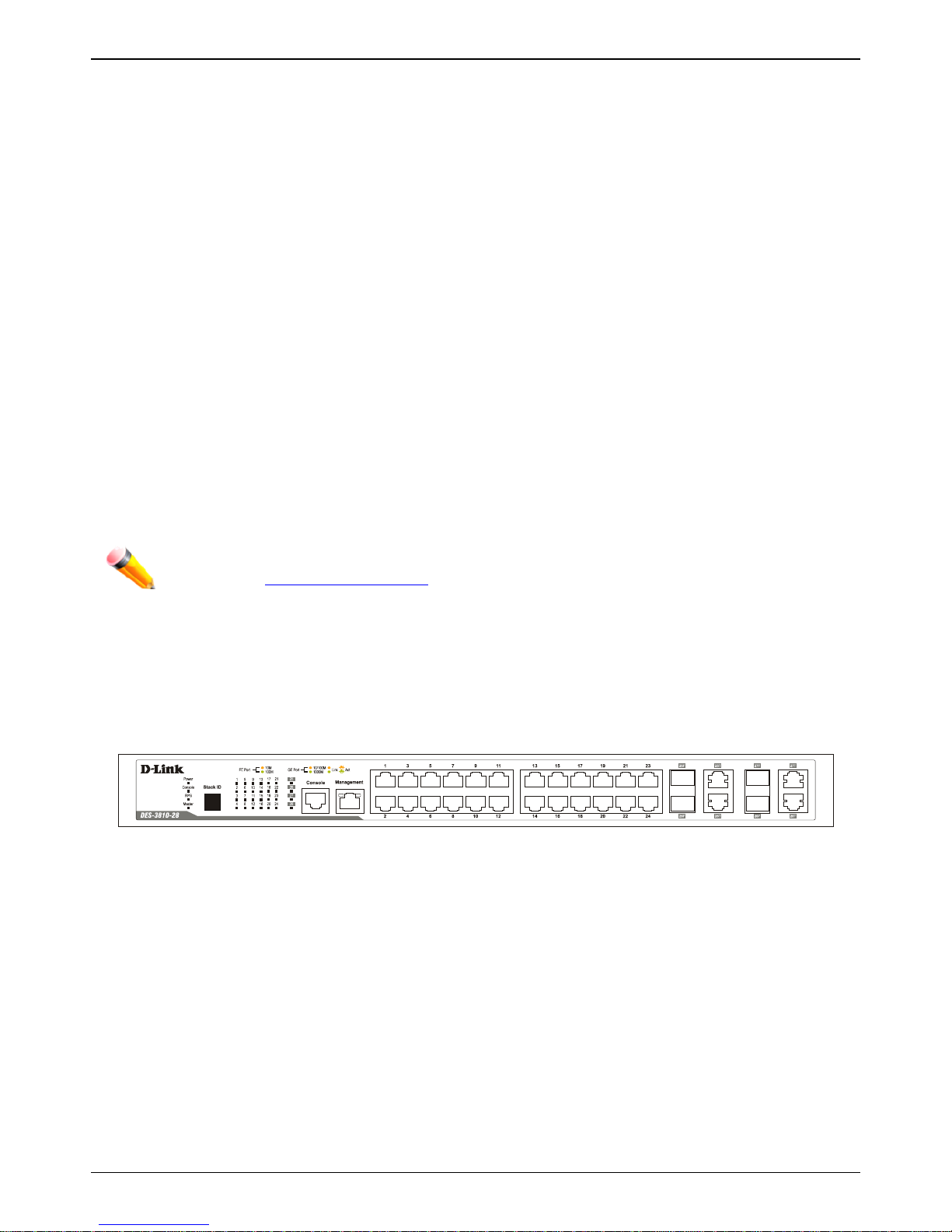
Front-Panel Components
The front panel of the Switch consists of LED indicators for Power, Console, RPS, and for Link/Act for each port on
the Switch including SFP port LEDs. A separate table below describes LED indicators in more detail.
Figure 1–1 Front panel view of a DES-3810-Series Switch

xStack® DES-3810 Series Layer 3 Ethernet Managed Switch Hardware Insta llati on G uide
12
LED Indicators
The DES-3810 Series front panel presents LED indicators for Power, Console, RPS, Master (stack control), Stack ID
and Link/Act indicators for all ports including the Gigabit Ethernet ports.
Figure 1–2 LED indicators for a DES-3810 Series Switch
LED Description
Power
This LED will light green after powering the Switch on to indicate the ready state of the
device. The indicator is dark when the Switch is no longer receiving power (i.e. powered
off).
Console
This LED will blink green during the Power-On Self Test (POST). When the POST is
finished, the LED goes dark. The indicator will light steady green when a user is logged
in through the console port, remote Telnet or Web.
RPS
This LED will light green if the Redundant Powers Supply is in use. If the indicator is off,
the RPS is not in use.
Master
For standalone Switches, this will light green. For stacked Switches, a solid Green light
indicates this unit is the Master of the stack. (Note: Switch stacking is not available in
Release 1.0)
FE Port
A steady green light denotes a valid 100Mbps link on the port while a blinking green light
indicates activity on the port (at 100Mbps). A steady amber light denotes a valid 10Mbps
link on the port while a blinking amber light indicates activity on the port (at 10Mbps).
These LEDs will remain dark if there is no link/activity on the port.
GE Port
LED indicators for the Combo ports are located above the ports. A steady green light
denotes a valid 1000Mbps link on the port while a blinking green one indicates activity
on the port (at 1000Mbps). A steady amber light denotes a valid 10 or 100Mbps link on
the port while a blinking amber one indicates activity on the port (at 10 or 100Mbps).
These LEDs will remain dark if there is no link/activity on the port.
Stack ID
For standalone Switches, this will display number 1. For stacked Switches, this indicates
the position in the stacking box ID. (Note: Switch stacking is not avai lab le in Release
1.0)
Management Port
Link/Act LEDs
The Management Port on the front panel presents LED indicators for Link and Activity.
The left LED will light steady green for a valid 10/100Mbps link; the upper right LED will
blink green when the port is active. The LED remain dark when there is no link or
activity.
xStack® DES-3810 Series Layer 3 Ethernet Managed Switch Hardware Insta llati on G uide
13
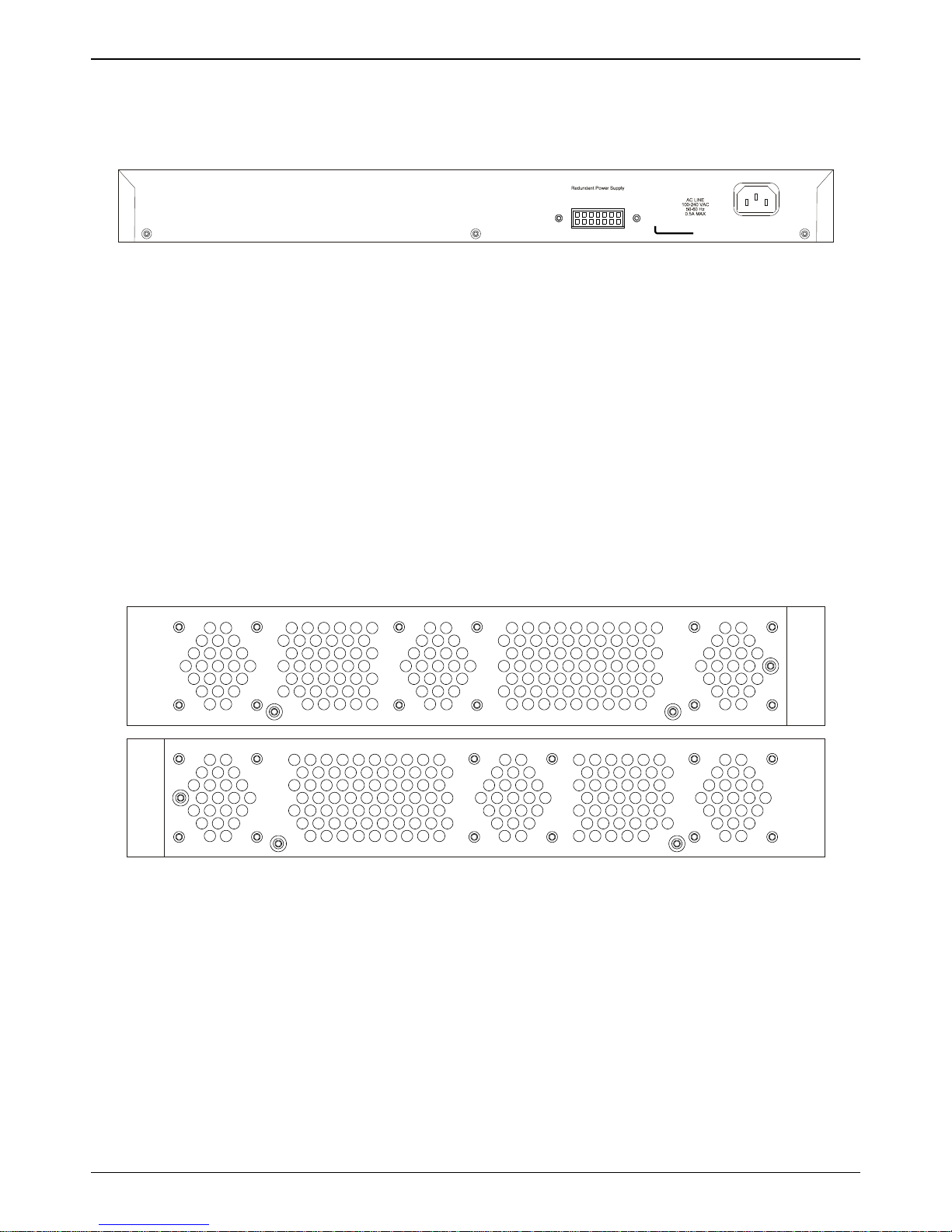
Rear Panel Description
The rear panel contains an AC power connector.
Figure 1–3 Rear panel view of a DES-3810 Series Switch
The AC power connector is a standard three-pronged connector that supports the power cord. Plug-in the female
connector of the provided power cord into this socket, and the male side of the cord into a power outlet. The DES3810 Series automatic al ly adjus ts the power setting to any supply voltage in the range from 100 ~ 240 VAC at 50 ~ 60
Hz. In addition, an optional external Redundant Power Supply (DPS-200) can be plugged into the connector displayed
above. When the internal power fails, this optional external RPS will take over all the power immediately and
automatically.
Side Panel Description
The system heat vents located on each side dissipate heat. Do not block these openings. Leave at least 6 inches of
space at the rear and sides of the Switch for pr o per ve nti lat ion. Be rem inded that w ithout proper heat dissi pat ion and
air circulation, system components might overheat, which could lead to system failure or even severely damage
components.
Figure 1–4 Identical side panels of a DES-3810 Series Switch

xStack® DES-3810 Series Layer 3 Ethernet Managed Switch Hardware Insta llati on G uide
14
Chapter 2 Installation
Package Contents
Installation Guidelines
Installing the Switch without a Rack
Rack Installation
Power On
Installing SFP Ports
Package Contents
Open the shipping carton of the Switch and carefully unpack its contents. The carton should contain the following
items:
• One DES-3810 Series Switch
• One Quick Installation Guide
• One AC power cord
• One RJ-45 to RS-232 console
• One mounting kit (two brackets and screws)
• Four rubber feet with adhesive backing
• One CD kit for User’s Guide/CLI/D-View module
If any item is missing or damaged, please contact your local D-Link Reseller for replacement.
Installation Guidelines
Please follow these guidelines for setting up the Switch:
• Install the Switch on a sturdy, level surface that can support at least 6.6 lb. (3 kg) of weight. Do not place heavy
objects on the Switch.
• The power outlet should be within 1.82 meters (6 feet) of the Switch.
• Visually inspect the power cord and see that it is fully secured to the AC po wer por t.
• Make sure that there is proper heat dissipation from and adequate ventilation around the Switch. Leave at least
10 cm (4 inches) of space at the front and rear of the Switch for ventilation.
• Install the Switch in a fairly cool and dry place for the acceptable temperature and humidity operating ranges.
• Install the Switch in a site free from strong electromagnetic field generators (such as motors), vibration, dust,
and direct exposure to sunlight.
• When installing the Switch on a level surface, attach the rubber feet to the bottom of the device. The rubber
feet cushion the Switch, protect the casing from scratches and prevent it from scratching other surfaces.
xStack® DES-3810 Series Layer 3 Ethernet Managed Switch Hardware Insta llati on G uide
15
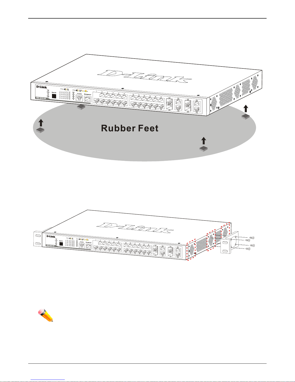
Installing the Switch without a Rack
First, attach the rubber feet included with the Switch if installing on a desktop or shelf. Attach these cushioning feet on
the bottom at each corner of the device. Allow enough ventilation space between the Switch and any other objects in
the vicinity.
Figure 2–1 Prepare a DES-3810 Series Switch for installation on a desktop or shelf
Attaching Brackets to a Switch for Rack Mounting
The Switch can be mounted in a standard 19" rack using the provided mounting brackets. Use the following diagrams
as a guide.
Figure 2–2 Fasten mounting brackets on a DES-3810 Series Switch
Fasten the mounting brackets to the Switch using the screws provided. With the brackets attached securely, the
Switch can be mounted in a standard rack, as shown below.
Note: Please review the Installation Guidelines above before installing the Switch in a rack. Make
sure there is adequate space around the Switch to allow for proper air flow, ventilation and cooling.
xStack® DES-3810 Series Layer 3 Ethernet Managed Switch Hardware Insta llati on G uide
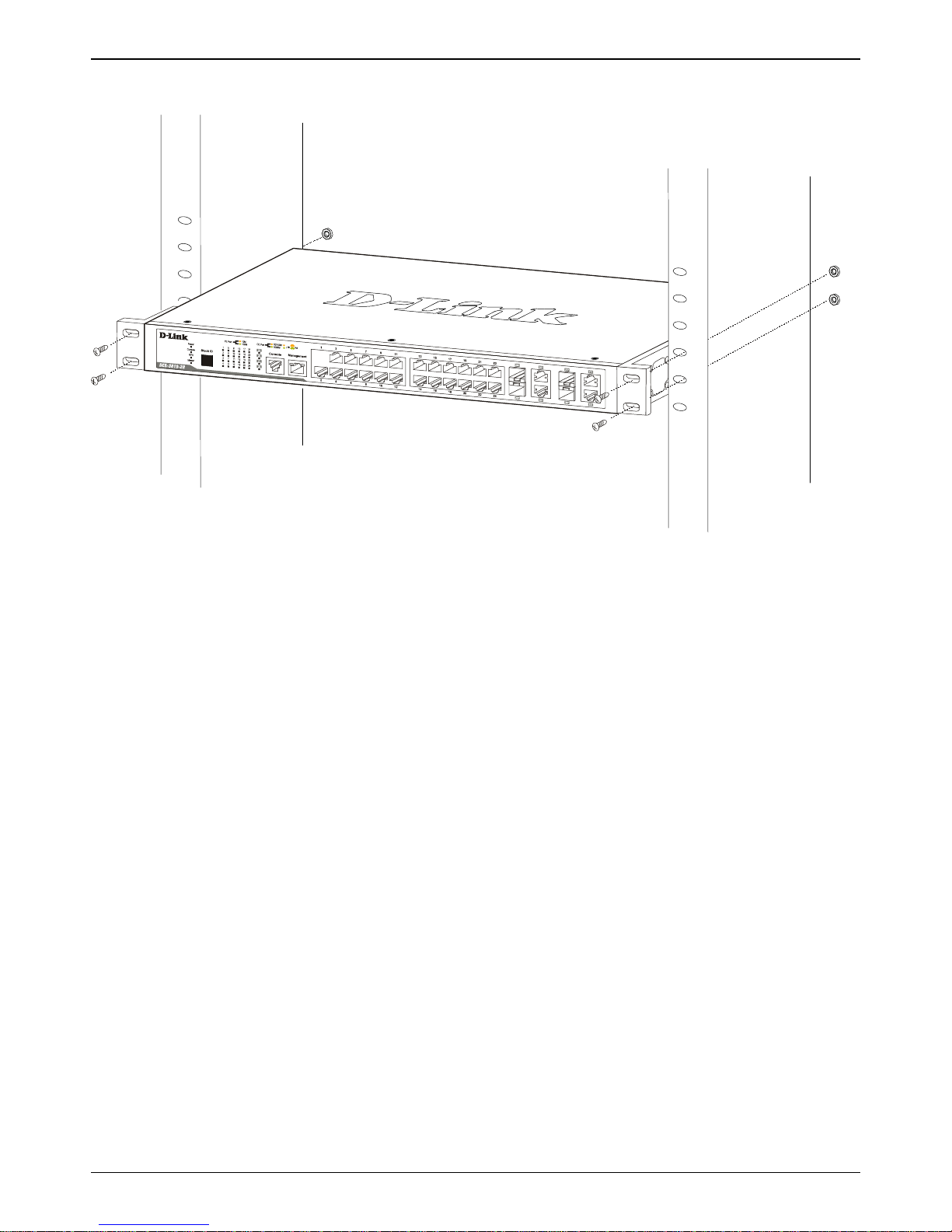
16
Mounting the Switch in a Standard 19" Rack
Figure 2–3 Installing a DES-3810 Series Switch in a rack
Power On
1. Plug one end of the AC power cord into the power connector of the Switch and the other end into the local
power source outlet.
2. After powering on the Switch, the LED indicators will momentarily blink green. This blinking of the LED
indicators represents a reset of the system.
Power Failure
As a precaution, in the event of a power failure, unplug the Switch. When power is resumed, plug the Switch back in.
xStack® DES-3810 Series Layer 3 Ethernet Managed Switch Hardware Insta llati on G uide
17
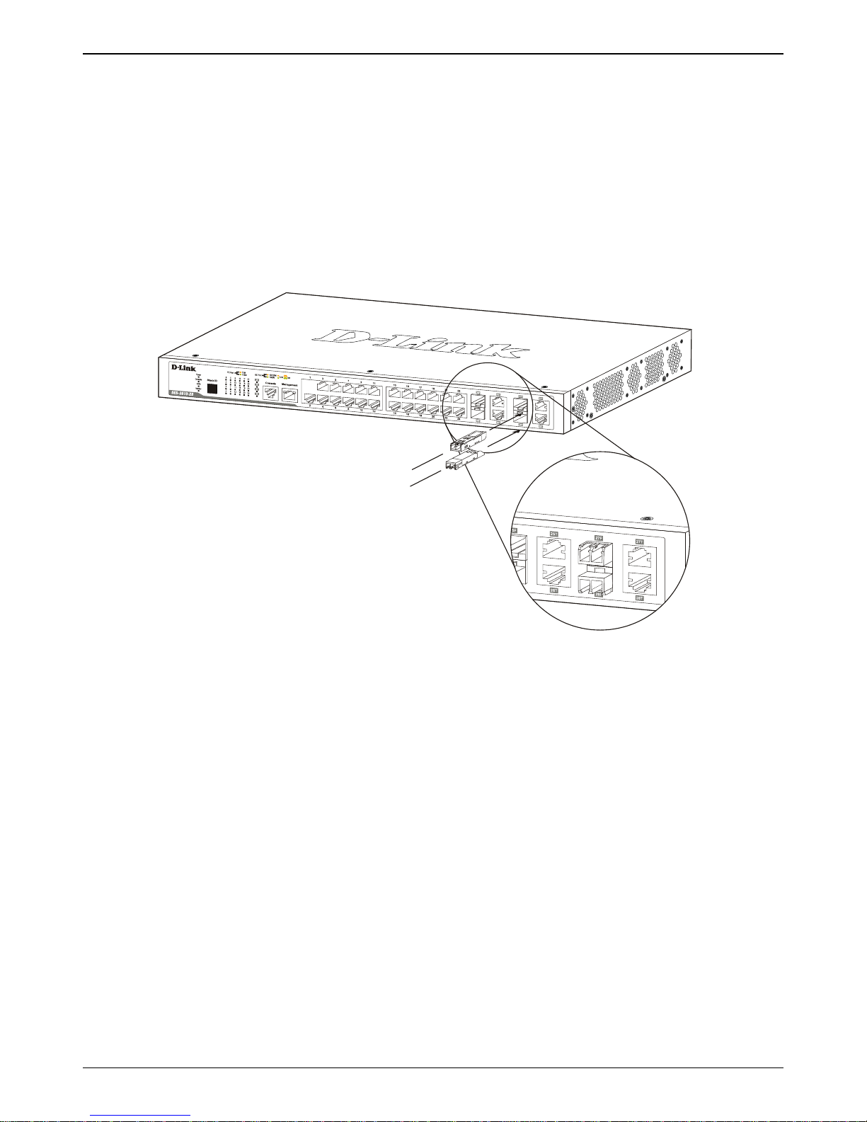
Installing SFP Ports
The Switch is equipped with SFP (Small Form Factor Portable) ports, which are to be used with fiber-optical
transceiver cabling in order to uplink various other networking devices for a gigabit link that may span great distances.
These SFP ports support full-duplex transmissions, have auto-negotiation and can be used with DEM-310GT
(1000BASE-LX), DEM-311GT (1000BASE-SX), DEM-312GT2 (1000BASE-SX), DEM-314GT (1000BASE-LH) and
DEM-315GT (1000BASE-ZX) transceivers. See the figure below for installing the SFP ports in the Switch. In addition,
DEM-210 (Single Mode, 100BASE-FX) and DEM-211 (Multi Mode, 100BASE-FX) SFP transceivers are supported.
WDM transceivers supported include DEM-330T (TX-1550/RX-1310 nm), DEM-330R (TX-1310/RX-1550 nm), DEM331T (TX-1550/RX-1310 nm), DEM-331R (TX1310/RX-1550 nm), DEM-220T (100BASE-BX-D, TX-1550/RX-1310
nm), and DEM-220R (100BASE-BX-U, TX-1310/RX-1550 nm).
Figure 2–4 Inserting fiber-optic transceivers into a DES-3810 Series Switch
xStack® DES-3810 Series Layer 3 Ethernet Managed Switch Hardware Insta llati on G uide
18
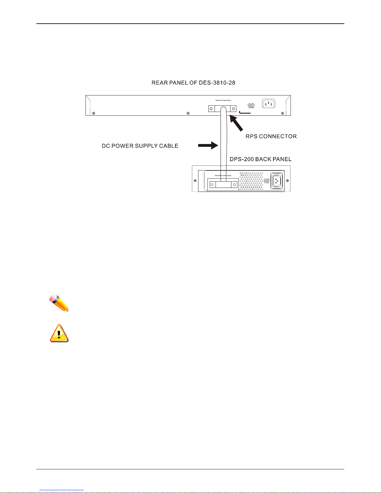
Connect to RPS
The DPS-200 is connected to the Master Switch using a 14-pin DC power cable. A standard, three-pronged AC power
cable connects the redundant power supply to the main power source.
Figure 2–5 Connecting a DES-3810 Series Switch to the DPS-200
1. Insert one end of the 14-pin DC power cable into the receptacle on the switch and the other end into the
redundant power supply.
2. Using a standard AC power cable, connect the redundant power supply to the main AC power source. A
green LED on the front of the DPS-200 will glow to indicate a successful connection.
3. Re-connect the switch to the AC power source. The LED indicator will show that a redundant power supply is
now in operation.
4. No change in switch configuration is necessary for this installation.
Note: See the DPS-200 documentation for more information.
CAUTION: DO NOT use the DES-38 10 Seri es Switc h with any redundant power system other
than the DPS-200.
 Loading...