

D-Link DES-3624i, DES-3624, DES-3624iF, DES-3624iFM, DES-3624F User Manual
...
DES-3624 Series
Stackable NWay Ethernet Switch
User’s Guide
Fifth Edition (December 2001)
651S3624.055
Printed In Taiwan
RECYCLABLE

Wichtige Sicherheitshinweise
1. Bitte lesen Sie sich diese Hinweise sorgfältig durch.
2. Heben Sie diese Anleitung für den spätern Gebrauch auf.
3. Vor jedem Reinigen ist das Gerät vom Stromnetz zu trennen. Vervenden Sie keine Flüssig- oder Aerosolreiniger. Am besten dient ein angefeuchtetes
Tuch zur Reinigung.
4. Um eine Beschädigung des Gerätes zu vermeiden sollten Sie nur Zubehörteile verwenden, die vom Hersteller zugelassen sind.
5. Das Gerät is vor Feuchtigkeit zu schützen.
6. Bei der Aufstellung des Gerätes ist auf sichern Stand zu achten. Ein Kippen oder Fallen könnte Verletzungen hervorrufen. Verwenden Sie nur sichere
Standorte und beachten Sie die Aufstellhinweise des Herstellers.
7. Die Belüftungsöffnungen dienen zur Luftzirkulation die das Gerät vor Überhitzung schützt. Sorgen Sie dafür, daß diese Öffnungen nicht abgedeckt
werden.
8. Beachten Sie beim Anschluß an das Stromnetz die Anschlußwerte.
9. Die Netzanschlußsteckdose muß aus Gründen der elektrischen Sicherheit einen Schutzleiterkontakt haben.
10. Verlegen Sie die Netzanschlußleitung so, daß niemand darüber fallen kann. Es sollete auch nichts auf der Leitung abgestellt werden.
11. Alle Hinweise und Warnungen die sich am Geräten befinden sind zu beachten.
12. Wird das Gerät über einen längeren Zeitraum nicht benutzt, sollten Sie es vom Stromnetz trennen. Somit wird im Falle einer Überspannung eine
Beschädigung vermieden.
13. Durch die Lüftungsöffnungen dürfen niemals Gegenstände oder Flüssigkeiten in das Gerät gelangen. Dies könnte einen Brand bzw. Elektrischen Schlag
auslösen.
14. Öffnen Sie niemals das Gerät. Das Gerät darf aus Gründen der elektrischen Sicherheit nur von authorisiertem Servicepersonal geöffnet werden.
15. Wenn folgende Situationen auftreten ist das Gerät vom Stromnetz zu trennen und von einer qualifizierten Servicestelle zu überprüfen:
a – Netzkabel oder Netzstecker sint beschädigt.
b – Flüssigkeit ist in das Gerät eingedrungen.
c – Das Gerät war Feuchtigkeit ausgesetzt.
d – Wenn das Gerät nicht der Bedienungsanleitung ensprechend funktioniert oder Sie mit Hilfe dieser Anleitung keine Verbesserung erzielen.
e – Das Gerät ist gefallen und/oder das Gehäuse ist beschädigt.
f – Wenn das Gerät deutliche Anzeichen eines Defektes aufweist.
16. Bei Reparaturen dürfen nur Orginalersatzteile bzw. den Orginalteilen entsprechende Teile verwendet werden. Der Einsatz von ungeeigneten
Ersatzteilen kann eine weitere Beschädigung hervorrufen.
17. Wenden Sie sich mit allen Fragen die Service und Repartur betreffen an Ihren Servicepartner. Somit stellen Sie die Betriebssicherheit des Gerätes
sicher.
18. Zum Netzanschluß dieses Gerätes ist eine geprüfte Leitung zu verwenden, Für einen Ne nnstrom bis 6A und einem Gerätegewicht grßer 3kg ist eine
Leitung nicht leichter als H05VV-F, 3G, 0.75mm2 einzusetzen.

WARRANTIES EXCLUSIVE
IF THE D-LINK PRODUCT DOES NOT OPERATE AS WARRANTED ABOVE, THE CUSTOMER'S SOLE REMEDY SHALL BE, AT D-LINK'S OPTION,
REPAIR OR REPLACEMENT. THE FOREGOING WARRANTIES AND REMEDIES ARE EXCLUSIVE AND ARE IN LIEU OF ALL OTHER WARRANTIES,
EXPRESSED OR IMPLIED, EITHER IN FACT OR BY OPERATION OF LAW, STATUTORY OR OTHERWISE, INCLUDING WARRANTIES OF
MERCHANTABILITY AND FITNESS FOR A PARTICULAR PURPOSE. D-LINK NEITHER ASSUMES NOR AUTHORIZES ANY OTHER PERSON TO
ASSUME FOR IT ANY OTHER LIABILITY IN CONNECTION WITH THE SALE, INSTALLATION MAINTENANCE OR USE OF D-LINK'S PRODUCTS
D-LINK SHALL NOT BE LIABLE UNDER THIS WARRANTY IF ITS TESTING AND EXAMINATION DISCLOSE THAT THE ALLEGED DEFECT IN THE
PRODUCT DOES NOT EXIST OR WAS CAUSED BY THE CUSTOMER'S OR ANY THIRD PERSON'S MISUSE, NEGLECT, IMPROPER INSTALLATION OR
TESTING, UNAUTHORIZED ATTEMPTS TO REPAIR, OR ANY OTHER CAUSE BEYOND THE RANGE OF THE INTENDED USE, OR BY ACCIDENT,
FIRE, LIGHTNING OR OTHER HAZARD.
LIMITATION OF LIABILITY
IN NO EVENT WILL D-LINK BE LIABLE FOR ANY DAMAGES, INCLUDING LOSS OF DATA, LOSS OF PROFITS, COST OF COVER OR OTHER
INCIDENTAL, CONSEQUENTIAL OR INDIRECT DAMAGES ARISING OUT THE INSTALLATION, MAINTENANCE, USE, PERFORMANCE, FAILURE OR
INTERRUPTION OF A D- LINK PRODUCT, HOWEVER CAUSED AND ON ANY THEORY OF LIABILITY. THIS LIMITATION WILL APPLY EVEN IF DLINK HAS BEEN ADVISED OF THE POSSIBILITY OF SUCH DAMAGE.
IF YOU PURCHASED A D-LINK PRODUCT IN THE UNITED STATES, SOME STATES DO NOT ALLOW THE LIMITATION OR EXCLUSION OF
LIABILITY FOR INCIDENTAL OR CONSEQUENTIAL DAMAGES, SO THE ABOVE LIMITATION MAY NOT APPLY TO YOU.

Limited Warranty
Hardware:
D-Link warrants each of its hardware products to be free from defects in workmanship and materials under normal use and service for a period commencing
on the date of purchase from D-Link or its Authorized Reseller and extending for the length of time stipulated by the Authorized Reseller or D-Link Branch
Office nearest to the place of purchase.
This Warranty applies on the condition that the product Registration Card is filled out and returned to a D-Link office within ninety (90) days of purchase. A
list of D-Link offices is provided at the back of this manual, together with a copy of the Registration Card.
If the product proves defective within the applicable warranty period, D-Link will provide repair or replacement of the product. D-Link shall have the sole
discretion whether to repair or replace, and replacement product may be new or reconditioned. Replacement product shall be of equivalent or better
specifications, relative to the defective product, but need not be identical. Any product or part repaired by D-Link pursuant to this warranty shall have a
warranty period of not less than 90 days, from date of such repair, irrespective of any earlier expiration of original warranty period. When D-Link provides
replacement, then the defective product becomes the property of D-Link.
Warranty service may be obtained by contacting a D-Link office within the applicable warranty period, and requesting a Return Material Authorization (RMA)
number. If a Registration Card for the product in question has not been returned to D-Link, then a proof of purchase (such as a copy of the dated purchase
invoice) must be provided. If Purchaser's circumstances require special handling of warranty correction, then at the time of requesting RMA number,
Purchaser may also propose special procedure as may be suitable to the case.
After an RMA number is issued, the defective product must be packaged securely in the original or other suitable shipping package to ensure that it will not
be damaged in transit, and the RMA number must be prominently marked on the outside of the package. The package must be mailed or otherwise shipped
to D-Link with all costs of mailing/shipping/insurance prepaid. D-Link shall never be responsible for any software, firmware, information, or memory data of
Purchaser contained in, stored on, or integrated with any product returned to D-Link pursuant to this warranty.
Any package returned to D-Link without an RMA number will be rejected and shipped back to Purchaser at Purchaser's expense, and D-Link reserves the right
in such a case to levy a reasonable handling charge in addition mailing or shipping costs.
Software:
Warranty service for software products may be obtained by contacting a D-Link office within the applicable warranty period. A list of D-Link offices is
provided at the back of this manual, together with a copy of the Registration Card. If a Registration Card for the product in question has not been returned
to a D-Link office, then a proof of purchase (such as a copy of the dated purchase invoice) must be provided when requesting warranty service. The term
"purchase" in this software warranty refers to the purchase transaction and resulting license to use such software.
D-Link warrants that its software products will perform in substantial conformance with the applicable product documentation provided by D-Link with such
software product, for a period of ninety (90) days from the date of purchase from D-Link or its Authorized Reseller. D-Link warrants the magnetic media, on
which D-Link provides its software product, against failure during the same warranty period. This warranty applies to purchased software, and to
replacement software provided by D-Link pursuant to this warranty, but shall not apply to any update or replacement which may be provided for download
via the Interne t, or to any update which may otherwise be provided free of charge.
D-Link's sole obligation under this software warranty shall be to replace any defective software product with product which substantially conforms to D-Link's
applicable product documentat ion. Purchaser assumes responsibility for the selection of appropriate application and system/platform software and associated
reference materials. D-Link makes no warranty that its software products will work in combination with any hardware, or any application or
system/platform software product provided by any third party, excepting only such products as are expressly represented, in D-Link's applicable product
documentation as being compatible. D-Link's obligation under this warranty shall be a reaso nable effort to provide compatibility, but D-Link shall have no
obligation to provide compatibility when there is fault in the third-party hardware or software. D-Link makes no warranty that operation of its software
products will be uninterrupted or abso lutely error-free, and no warranty that all defects in the software product, within or without the scope of D-Link's
applicable product documentation, will be corrected.
D-Link Offices for Registration and Warranty Service
The product's Registration Card, provided at the back of this manual, must be sent to a D-Link office. To obtain an RMA number for warranty service as to a
hardware product, or to obtain warranty service as to a software product, contact the D-Link office nearest you. An address/telepho ne/fax/e-mail/Web site
list of D-Link offices is provided in the back of this manual.
Trademarks
Copyright 2001 D-Link Corporation.
Contents subject to change without prior notice.
D-Link is a registered trademark of D-Link Corporation/D-Link Systems, Inc. All other trademarks belong to their
respective proprietors.
Copyright Statement

No part of this publication may be reproduced in any form or by any means or used to make any derivative such as
translation, transformation, or adaptation without permission from D-Link Corporation/D-Link Systems Inc., as
stipulated by the United States Copyright Act of 1976.
FCC Warning
This equipment has been tested and found to comply with the limits for a Class A digital device, pursuant to Part 15 of the
FCC Rules. These limits are designed to provide reasonable protection against harmful interference when the equipment
is operated in a commercial environment. This equipment generates, uses, and can radiate radio frequency energy and, if
not installed and used in accordance with this user’s guide, may cause harmful interference to radio communications.
Operation of this equipment in a residential area is likely to cause harmful interference in which case the user will be
required to correct the interference at his own expense.
This device complies with part 15 of the FCC Rules. Operation is subject to the following two conditions: (1) This device
may not cause harmful interference, and (2) this device must accept any interference received, including interference that
may cause undesired operation.
CE Mark Warning
This is a Class A product. In a domestic environment, this product may cause radio interference in which case the user may
be required to take adequate measures.
Warnung!
Dies ist in Produkt der Klasse A. Im Wohnb ereich kann dieses Produkt Funkstoerungen verursachen. In diesem Fall kann
vom Benutzer verlangt werden, angemessene Massnahmen zu ergreifen.
Precaución!
Este es un producto de Clase A. En un entorno doméstico, puede causar interferencias de radio, en cuyo case, puede
requerirse al usuario para que adopte las medidas adecuadas.
Attention!
Ceci est un produit de classe A. Dans un environnement domestique, ce produit pourrait causer des interférences radio,
auquel cas l`utilisateur devrait prendre les mesures adéquates.
Attenzione!
Il presente prodotto appartiene alla classe A. Se utilizzato in ambiente domestico il prodotto può causare interferenze
radio, nel cui caso è possibile che l`utente debba assumere provvedimenti adeguati.
VCCI Warning
BSMI Warning

TABLE OF C ONTENTS
0 ABOUT THIS GUIDE................................................................................................................................................................................10
CONVENTIONS................................................................................................................................................................................................10
OVERVIEW OF THIS USER ’S GUIDE ............................................................................................................................................................. 10
1 INTRODUCTION......................................................................................................................................................................................11
FAST ETHERNET TECHNOLOGY .................................................................................................................................................................11
G IGABIT ETHERNET TECHNOLOGY ........................................................................................................................................................... 11
SWITCHING TECHNOLOGY ..........................................................................................................................................................................12
FEATURES.......................................................................................................................................................................................................12
Ports .............................................................................................................................................................................................................12
Performance features................................................................................................................................................................................13
Management ...............................................................................................................................................................................................13
2 UNPACKING AND SETUP......................................................................................................................................................................14
UNPACKING....................................................................................................................................................................................................14
SETUP .............................................................................................................................................................................................................. 14
DESKTOP OR SHELF INSTALLAT ION ......................................................................................................................................................... 14
RACK INSTALLATION ................................................................................................................................................................................... 15
POWER ON ...................................................................................................................................................................................................... 16
Power Failure............................................................................................................................................................................................16
3 IDENTIFYING EXTERNAL COMPONENTS.......................................................................................................................................17
FRONT PANEL ................................................................................................................................................................................................ 17
REAR PANEL...................................................................................................................................................................................................18
SIDE PANELS .................................................................................................................................................................................................. 18
STACK OPERATION......................................................................................................................................................................................19
OPTIONAL PLUG-IN MODULES...................................................................................................................................................................20
100BASE-FX (MT-RJ) Module...............................................................................................................................................................21
100BASE-FX (SC) Module......................................................................................................................................................................21
100BASE-TX Module................................................................................................................................................................................22
1000BASE-SX Gigabit Module...............................................................................................................................................................22
1000BASE-LX Gigabit Module...............................................................................................................................................................23
1000BASE-T Copper Gigabit Module...................................................................................................................................................23
LED INDICATORS...........................................................................................................................................................................................24
4 CONNECTING THE SWITCH................................................................................................................................................................26
SWITCH TO END NODE................................................................................................................................................................................26
SWITCH TO HUB OR SWITCH......................................................................................................................................................................26
10BASE-T Device.......................................................................................................................................................................................27
100BASE-TX Device..................................................................................................................................................................................27
5 SWITCH MANAGEMENT CONCEPTS ...............................................................................................................................................28
LOCAL CONSOLE MANAGEMENT...............................................................................................................................................................28
Diagnostic (Console) Port (RS-232 DCE)...........................................................................................................................................28
IP ADDRESSES AND SNMP COMMUNITY NAMES....................................................................................................................................29
TRAPS..............................................................................................................................................................................................................29
MIBS................................................................................................................................................................................................................30
PACKET FORWARDING.................................................................................................................................................................................30

Aging Time..................................................................................................................................................................................................30
Filtering Database....................................................................................................................................................................................31
SPANNING TREE ALGORITHM....................................................................................................................................................................31
STA Operation Levels...............................................................................................................................................................................31
On the Bridge Level................................................................................................................................................................................31
On the Port Level....................................................................................................................................................................................32
User-Changeable STA Parameters.........................................................................................................................................................32
Illustration of STA.....................................................................................................................................................................................33
PORT TRUNKING............................................................................................................................................................................................34
VLAN S & MAC-BASED BROADCAST DOMAINS.......................................................................................................................................35
MAC-Based Broadcast Domains............................................................................................................................................................36
IEEE 802.1Q VLANs..................................................................................................................................................................................36
802.1Q VLAN Segmentation.................................................................................................................................................................36
Sharing Resources Across 802.1Q VLANs ........................................................................................................................................37
802.1Q VLANs Spanning Multiple Switches......................................................................................................................................37
VLANs Over 802.1Q -compliant Switches...................................................................................................................................... 38
Port-Based VLANs.....................................................................................................................................................................................39
BROADCAST STORMS....................................................................................................................................................................................39
Segmenting Broadcast Domains .............................................................................................................................................................40
Eliminating Broadcast Storms................................................................................................................................................................40
6 USING THE CONSOLE I NTERFACE....................................................................................................................................................41
SETTING UP A CONSOLE.............................................................................................................................................................................41
CONNECTING TO THE SWITCH USING TELNET ....................................................................................................................................... 42
CONSOLE USAGE CONVENTIONS.................................................................................................................................................................42
FIRST TIME CONNECTING TO THE SWITCH.............................................................................................................................................42
User Accounts Management....................................................................................................................................................................44
Save Changes.............................................................................................................................................................................................45
LOGIN ON THE SWITCH CONSOLE BY REGISTERED USERS...................................................................................................................45
Create/Modify User Accounts.............................................................................................................................................................45
User Accounts Control Table...............................................................................................................................................................47
SETTING UP THE SWITCH...........................................................................................................................................................................48
System Configuration...............................................................................................................................................................................48
Configure IP Address............................................................................................................................................................................48
Configure Console..................................................................................................................................................................................49
Configure Switch Stack..........................................................................................................................................................................50
Information of Individual Switch Unit..............................................................................................................................................51
Advance Settings................................................................................................................................................................................52
Configure Port.........................................................................................................................................................................................53
Configure Trunk Groups........................................................................................................................................................................55
Configure Port Mirroring.......................................................................................................................................................................56
Configure Spanning Tree Protocol......................................................................................................................................................57
STP Parameter Settings....................................................................................................................................................................57
STP Custom Settings.........................................................................................................................................................................60
Configure Filtering and Forwarding Table..........................................................................................................................................61
Configure Static Forwarding Table.................................................................................................................................................62
Configure MAC Address Filtering....................................................................................................................................................63
Configure Static Multicast Filtering..................................................................................................................................................63
Configure IGMP ..................................................................................................................................................................................64
Configure VLANs & MAC-based Broadcast Domains....................................................................................................................67
Configure MAC-based Broadcast Domains..................................................................................................................................68
Configure Port-based VLANs..........................................................................................................................................................71
Configure 802.1Q VLANs.................................................................................................................................................................74
Configure GMRP.................................................................................................................................................................................79
Update Firmware and Configuration Files..........................................................................................................................................83
Special Note Concerning Firmware Updates......................................................................................................................................84
System Utilities...........................................................................................................................................................................................85

Ping Test..................................................................................................................................................................................................85
Save Settings to TFTP Server...............................................................................................................................................................86
Save Switch History to TFTP Server...................................................................................................................................................87
Clear Address Table...............................................................................................................................................................................88
Community Strings and Trap Stations..................................................................................................................................................88
SWITCH MONITORING ................................................................................................................................................................................. 89
Network Monitoring.................................................................................................................................................................................89
Traffic Statistics......................................................................................................................................................................................90
Port Utilization.....................................................................................................................................................................................91
Port Traffic Statistics...........................................................................................................................................................................92
Port Packet Error Statistics...............................................................................................................................................................93
Port Packet Analysis Statistics.........................................................................................................................................................94
Browse Address Table ..........................................................................................................................................................................95
Switch History.........................................................................................................................................................................................96
Browse IGMP Status..............................................................................................................................................................................96
Browse GVRP Status..............................................................................................................................................................................97
Browse GMRP Status.............................................................................................................................................................................98
RESETTING THE SWITCH.............................................................................................................................................................................99
Restart System ............................................................................................................................................................................................99
Factory Reset...........................................................................................................................................................................................100
Logout.......................................................................................................................................................................................................101
7 WEB-BASED NETWORK M ANAGEMENT.....................................................................................................................................102
INTRODUCTION...........................................................................................................................................................................................102
G ETTING STARTED..................................................................................................................................................................................... 102
MANAGEMENT ............................................................................................................................................................................................102
Configuration..........................................................................................................................................................................................103
IP Address.............................................................................................................................................................................................103
Switch Module......................................................................................................................................................................................104
Switch Module Information.............................................................................................................................................................105
Advanced Settings...............................................................................................................................................................................106
Port .......................................................................................................................................................................................................... 107
Trunk Groups........................................................................................................................................................................................109
Port Mirroring........................................................................................................................................................................................110
Spanning Tree Protocol.......................................................................................................................................................................110
STP Switch Settings.........................................................................................................................................................................111
STP Port Settings..............................................................................................................................................................................112
Forwarding and Filtering.....................................................................................................................................................................112
Static Forwarding Table..................................................................................................................................................................114
MAC Address Filtering Table.........................................................................................................................................................116
Static Multicast Filtering...................................................................................................................................................................118
IGMP.......................................................................................................................................................................................................119
IGMP Settings....................................................................................................................................................................................120
802.1Q IGMP.....................................................................................................................................................................................121
VLANs .................................................................................................................................................................................................... 124
MAC-Based Broadcast Domains...................................................................................................................................................125
Port-based VLANs...........................................................................................................................................................................130
802.1Q VLANs..................................................................................................................................................................................132
GMRP..................................................................................................................................................................................................136
Management ............................................................................................................................................................................................ 140
Community Strings and Trap Receivers............................................................................................................................................141
User Accounts Management..............................................................................................................................................................142
Console ..................................................................................................................................................................................................144
Monitoring...............................................................................................................................................................................................144
Switch Overview...................................................................................................................................................................................145
Port Utilization.......................................................................................................................................................................................146
Port Traffic Statistics............................................................................................................................................................................147

Port Error Packet Statistics..................................................................................................................................................................148
Port Packet Analysis Statistics...........................................................................................................................................................149
Browse Address Table ........................................................................................................................................................................151
IP Multicast & IGMP Information......................................................................................................................................................152
Browse GVRP Status............................................................................................................................................................................153
Browse GMRP Status...........................................................................................................................................................................154
Switch History.......................................................................................................................................................................................155
Maintenance............................................................................................................................................................................................155
Firmware and Configuration Update..................................................................................................................................................156
Save Settings To TFTP Server...........................................................................................................................................................157
Save Switch History To TFTP Server................................................................................................................................................158
Clear Address Table.............................................................................................................................................................................159
Save Changes........................................................................................................................................................................................160
Factory Reset........................................................................................................................................................................................161
Restart System......................................................................................................................................................................................162
8 TECHNICAL SPECIFICATIONS........................................................................................................................................................163
9 RJ-45 PIN SPECIFICATION...............................................................................................................................................................166
10 SAMPLE CONFIGURATION FILE.................................................................................................................................................168
Commands:............................................................................................................................................................................................168
Notes about the Configuration File:..................................................................................................................................................168
11 RUNTIME SOFTWARE DEFAULT SETTINGS............................................................................................................................170
12 INDEX ...................................................................................................................................................................................................171

Stackable NWay Ethernet Switch User’s Guide
10 About This Guide
0 A BOUT THIS GUIDE
This User’s Guide tells you how to install your Stackable NWay Ethernet Switch, how to connect it to your Ethernet
network, and how to set its configuration using either the built-in console interface or Web-based management (please note
that Netscape Communicator/Navigator, 4.x or later, or Microsoft Internet Explorer, 4.x or later, are recommended).
Conventions
References in this manual to the DES-3624 Series are frequently written simply as “Switch” or “Switches” where the text
applies to all models. Model numbers are normally used only to differentiate among specific Switches where necessary.
Unless differentiated by model number, all information applies to all models.
Overview of this User’s Guide
♦ Chapter 1, “Introduction.” Describes the Switch and its features.
♦ Chapter 2, “Unpacking and Setup.” Helps you get started with the basic installation of the Switch.
♦ Chapter 3, “Identifying External Components.” Describes the front panel, rear panel, side panels, optional plug-
in modules, and LED indicators of the Switch.
♦ Chapter 4, “Connecting the Switch.” Tells how you can connect the Switch to your Ethernet network.
♦ Chapter 5, “Switch Management Concepts.” Talks about Local Console Management via the RS-232 DCE console
port and other aspects about how to manage the Switch.
♦ Chapter 6, “Using the Console Interface.” Tells how to use the built-in console interface to change, set, and
monitor Switch performance and security.
♦ Chapter 7, “Web-Based Network Management.” Tells how to manage the Switch through an Internet browser.
♦ Appendix A, “Technical Specifications.” Lists the technical specifications of the Switch.
♦ Appendix B, “RJ-45 Pin Specifications.” Shows the details and pin assignments for the RJ-45
receptacle/connector.
♦ Appendix C, “Sample Configuration File.”
♦ Appendix D, “Runtime Software Default Settings.”

Stackable NWay Ethernet Switch User’s Guide
Introduction 11
11
1 INTRODUCTION
This section describes th e features of the Switch, as well as giving some background information about Ethernet/Fast
Ethernet, Gigabit Ethernet, and switching technology.
Fast Ethernet Technology
The growing importance of LANs and the increasing complexity of desktop computing applications are fueling the need for
high performance networks. A number of high-speed LAN technologies are proposed to provide greater bandwidth and
improve client/server response times. Among them, Fast Ethernet, or 100BASE -T, provides a non-disruptive, smooth
evolution from the current 10BASE -T technology. The dominating market position virtually guarantees cost effective and
high performance Fast Ethernet solutions in the years to come.
100Mbps Fast Ethernet is a standard specified by the IEEE 802.3 LAN committee. It is an extension of the 10Mbps
Ethernet standard with the ability to transmit and receive data at 100Mbps, while maintaining the Carrier Sense
Multiple Access with Collision Detection (CSMA/CD) Ethernet protocol.
Gigabit Ethernet Technology
Gigabit Ethernet is an extension of IEEE 802.3 Ethernet utilizing the same packet structure, format, and support for
CSMA/CD protocol, full duplex, flow control, and management objects, but with a tenfold increase in theoretical
throughput over 100Mbps Fast Ethernet and a one hundred-fold increase over 10Mbps Ethernet. Since it is compatible
with all 10Mbps and 100Mbps Ethernet environments, Gigabit Ethernet provides a straightforward upgrade without
wasting a company’s existing investment in hardware, software, and trained personnel.
The increased speed and extra bandwidth offered by Gigabit Ethernet is essential to coping with the network bottlenecks
that frequently develop as computers and their busses get faster and more users use applications that generate more
traffic. Upgrading key components, such as your backbone and servers to Gigabit Ethernet can greatly improve network
response times as well as significantly speed up the traffic between your subnets.
Gigabit Ethernet enables fast optical fiber connections to support video conferencing, complex imaging, and similar dataintensive applications. Likewise, since data transfers occur 10 times faster than Fast Ethernet, servers outfitted with
Gigabit Ethernet NIC’s are able to perform 10 times the number of operations in the same amount of time.
In addition, the phenomenal bandwidth delivered by Gigabit Ethernet is the most cost-effective method to take advantage
of today and tomorrow’s rapidly improving switching and routing internetworking technologies. And with expected
advances in the coming years in silicon technology and digital signal processing that will enable Gigabit Ethernet to
eventually operate over unshielded twisted-pair (UTP) cabling, outfitting your network with a powerful 1000Mbps-capable
backbone/server connection creates a flexible foundation for the next generation of network technology products.

Stackable NWay Ethernet Switch User’s Guide
12 Introduction
Switching Technology
Another key development pushing the limits of Ethernet technology is in the field of switching technology. A switch bridges
Ethernet packets at the MAC address level of the Ethernet protocol transmitting among connected Ethernet, Fast
Ethernet, or Gigabit Ethernet LAN segments.
Switching is a cost-effective way of increasing the total network capacity available to users on a local area network. A
switch increases capacity and decreases network loading by making it possible for a local area network to be divided into
different segments which don’t compete with each other for network transmission capacity, giving a decreased load on
each.
The switch acts as a high-speed selective bridge between the individual segments. Traffic tha t needs to go from one
segment to another (from one port to another) is automatically forwarded by the switch, without interfering with any other
segments (ports). This allows the total network capacity to be multiplied, while still maintaining the same network
cabling and adapter cards.
For Fast Ethernet or Gigabit Ethernet networks, a switch is an effective way of eliminating problems of chaining hubs
beyond the “two -repeater limit.” A switch can be used to split parts of the network into different collision domains, for
example, making it possible to expand your Fast Ethernet network beyond the 205 meter network diameter limit for
100BASE -TX networks. Switches supporting both traditional 10Mbps Ethernet and 100Mbps Fast Ethernet are also ideal
for bridging between existing 10Mbps networks and new 100Mbps networks.
Switching LAN technology is a marked improvement over the previous generation of network bridges, which were
characterized by higher latencies. Routers have also been used to segment local area networks, but the cost of a router and
the setup and maintenance required make routers relatively impractical. Today’s switches are an ideal solution to most
kinds of local area network congestion problems.
Features
The DES -3624 series of Switches can include one master (DES -3624I, DES -3624iF, or DES -3624iFM) and up to three
clients (DES-3624, DES-3624F, or DES -3624FM). They are designed for easy installation and high performance in an
environment where traffic on the network and the number of users increases continuously.
Switch features include:
Ports
♦ 20 high performance NWay ports all operating at 10/100 Mbps for connection to servers and hubs (19 ports 10/100
fixed Ethernet TP interface and one MDI-II/MDI-X jack connection are supported) (DES -3624I, DES-3624iF, and
DES-3624iFM) or 22 high performance NWay ports all operating at 10/100 Mbps for connection to servers and hubs
(20 ports 10/100 fixed Ethernet TP interface and two MDI-II/MDI-X jack connections are supported) (DES -3624,
DES-3624F, and DES-3624FM).
♦ All ports can be auto-negotiated between 10Mbps/100Mbps, half-or full-duplex connections.
♦ Gigabit uplink/MDI-II (media dependent interface) slide-in module in the rear panel for uplink to another Switch.
One-port or two-port models are available (DES-3624i, DES-3624iF, and DES-3624iFM only).
♦ RS-232 DCE console port for diagnosing the Switch via a connection to a PC and Console/Out-of-band management
(DES-3624i, DES-3624iF, or DES-3624iFM only).
♦ One slide-in module interface in the front panel for 1 or 2 ports 10/100M Ethernet connection. Three optional
modules are available: 2-port TX, 2-port FX (MT-RJ), and 1-port FX (SC).

Stackable NWay Ethernet Switch User’s Guide
Introduction 13
♦ Stacking Input/Output port slide-in module in the rear panel for stacking to another device to implement a high-port
count, manageable switch. Three-port module for master device and one-port module for a client device.
Performance features
♦ Store and forward switching scheme capability to support rate adaptation and protocol conversion.
♦ Full- and half-duplex for 10Mbps and 100Mbps connections. The optional 1000BASE-SX and 1000BASE -LX
modules operate at full-duplex only. The optional 1000BASE -T module, however, can be negotiated to 1000M/half.
♦ Auto polarity detection and correction of incorrect polarity on the receive twisted pair at each port.
♦ Data forwarding rate 14,880 pps per port at 100% of wire-speed for 10Mbps speed.
♦ Data forwarding rate 144,810 pps per port at 100% of wire-speed for 100Mbps speed.
♦ Data forwarding rate 1,488,100 pps per port at 100% of wire-speed for 1000Mbps speed.
♦ Data filtering rate eliminates all error packets, runts, etc. at 14,880 pps per port at 100% of wire-speed for 10Mbps
speed.
♦ Data filtering rate eliminates all error packets, runts, etc. at 144,810 pps per port at 100% of wire-speed for
100Mbps speed.
♦ Data filtering rate eliminates all error packets, runts, etc. at 1,488,100 pps per port at 100% of wire-speed for
1000Mbps speed.
♦ 12K active MAC address entry table per device with automatic learning and aging (10 to 9999 seconds).
♦ 12 MB packet buffer per device.
♦ Supports Broadcast Storm filtering.
♦ Supports IGMP Multicast snooping.
Management
♦ RS-232 console port for out-of-band network management via a console terminal or PC.
♦ Spanning Tree Algorithm Protocol for creation of alternative backup paths and prevention of indefinite network
loops.
♦ Fully configurable either in-band or out-of-band control via SNMP based software.
♦ Flash memory for software upgrade. This can be done in-band via BOOTP/TFTP. Out-of-band console can also
initiate a download request.
♦ Built-in SNMP management: Bridge MIB (RFC 1493), RMON MIB (RFC 1757), MIB-II (RFC 1213), and Entity
MIB (RFC 2737).

Stackable NWay Ethernet Switch User’s Guide
14 Unpacking and Setup
22
2 U NPACKING AND SETUP
This chapter provides unpacking and setup information for the Switch.
Unpacking
Open the shipping carton of the Switch and carefully unpack its contents. The carton should contain the following items:
♦ One Stackable NWay Ethernet Switch
♦ Mounting kit: two mounting brackets and screws
♦ Four rubber feet with adhesive backing
♦ One AC power cord
♦ One RS-232 cable (master only)
♦ This user’s guide on CD-ROM with a Registration Card
If any item is found missing or damaged, please contact your local D -Link reseller for replacement.
Setup
The setup of the Switch can be performed using the following steps:
♦ The surface must support at least 5 kg.
♦ The power outlet should be within 1.82 meters (6 feet) of the device.
♦ Visually inspect the power cord and see that it is secured fully to the AC power connector.
♦ Make sure that there is proper heat dissipation from and adequate ventilation around the Switch. Do not place
heavy objects on the Switch.
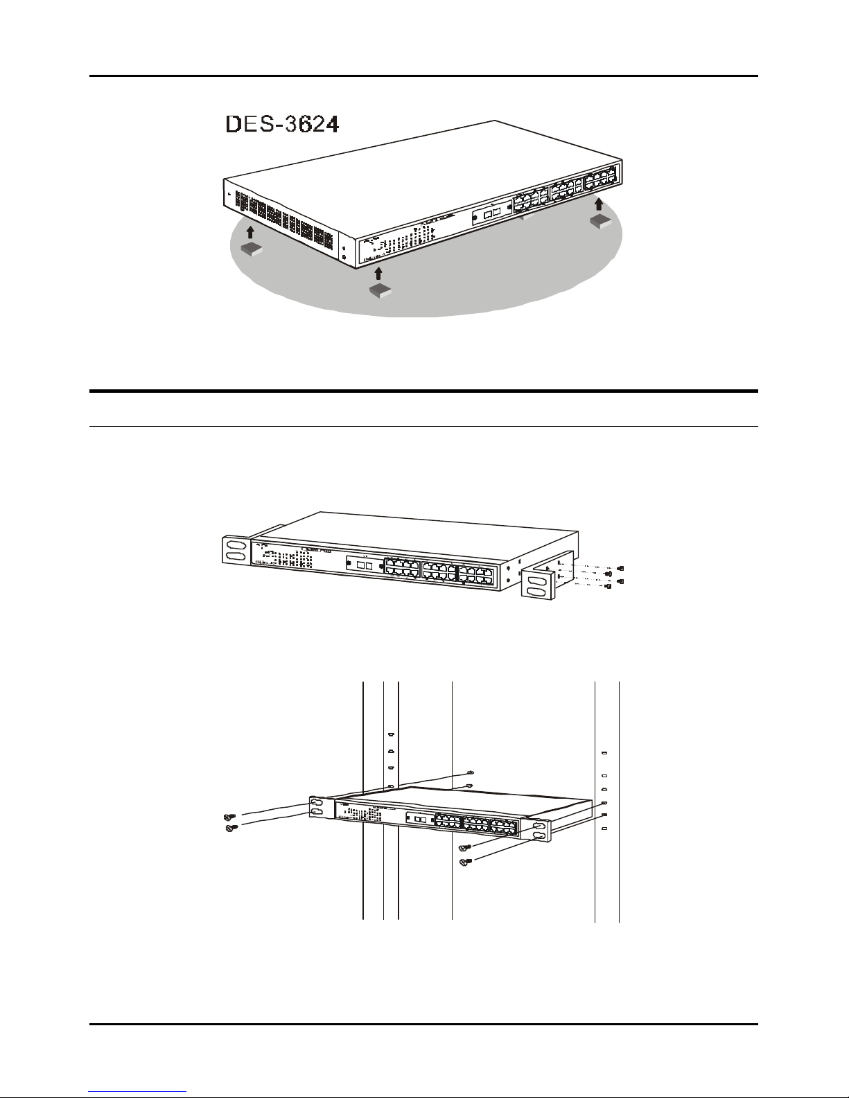
Desktop or Shelf Installation
When installing the Switch on a desktop or shelf, the rubber feet included with the device must be first attached. Attach
these cushioning feet on the bottom at each corner of the device. Allow enough ventilation space between the device and the
objects around it.
Stackable NWay Ethernet Switch User’s Guide
Unpacking and Setup 15
Figure 2-1. Switch installed on a Desktop or Shelf
Rack Installation
The Switch can be mounted in an EIA standard size, 19-inch rack, which can be placed in a wiring closet with other
equipment. To install, attach the mounting brackets on the Switch’s side panels (one on each side) and secure them with
the screws provided.
Figure 2-2A. Attaching the mounting brackets to the Switch
Then, use the screws provided with the equipment rack to mount the Switch in the rack.
Figure 2-2B. Installing the Switch in an equipment rack

Stackable NWay Ethernet Switch User’s Guide
16 Unpacking and Setup
Power On
The Switch can be used with AC power sources 100 - 240 VAC, 50 - 60 Hz. The power switch is located at the rear of the
unit adjacent to the AC power connector and the system fan. The Switch’s power supply will adjust to the local power
source automatically and may be turned on without having any or all LAN segment cables connected.
After the power switch is turned on, the LED indicators should respond as follows:
♦ All LED indicators will momentarily blink. This blinking of the LED indicators represents a reset of the system.
♦ The power LED indicator will blink while the Switch loads onboard software and performs a self-test. After
approximately 40 seconds, the LED will light continuously to indicate the Switch is in a ready state.
♦ The console LED indicator will remain ON if there is a connection at the RS-232 port, otherwise this LED indicator
is OFF.
♦ The 100M LED indicator may remain ON or OFF depending on the transmission speed.
Power Failure
As a precaution, the Switch should be unplugged in case of power failure. When power is resumed, plug the Switch back in.
Stackable NWay Ethernet Switch User’s Guide
Identifying External Components 17
33
3 IDENTIFYING E XTERNAL COMPONENTS
This chapter describes the front panel, rear panel, side panels, optional plug-in modules, and LED indicators of the Switch
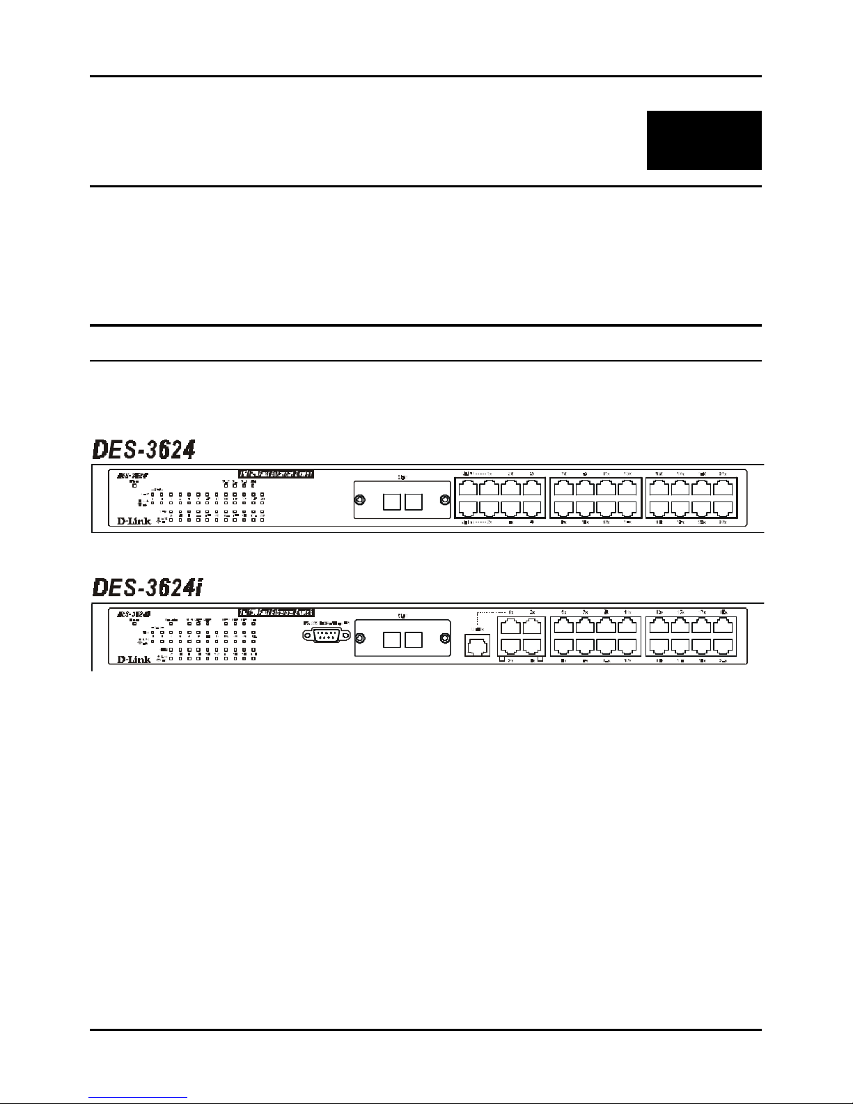
Front Panel
The front panel of the Switch consists of either 22 or 20 (10/100 Mbps) Ethernet/Fast Ethernet ports, two or one uplink
jacks, a slide-in module slot for 10/100 Mbps Ethernet ports, an RS-232 communication port (DES -3624i, DES-3624iF,
and DES-3624iFM only), and LED indicators.
Figure 3-1. Front panel view of the Switches
♦ Comprehensive LED indicators display the conditions of the Switch and status of the network. A description of
these LED indicators follows (see LED Indicators).
♦ An RS-232 DCE console port is used to diagnose the Switch via a connection to a PC and Local Console
Management (DES-3624i, DES-3624iF, and DES-3624iFM only).
♦ Twenty or twenty-two high performance NWay ports all operate at 10/100 Mbps for connection to servers and hubs.
All ports can be auto-negotiated between 10Mbps or 100Mbps.
♦ A slide-in module slot (labeled Slot1) for 10/100 Mbps Ethernet ports can accommodate the following modules: 2-
port TX, 2-port FX (MT-RJ), or 1-port FX (SC).
♦ One or two MDI-II uplink jacks are supported. Port numbers 1 and 2 on the DES -3624, DES -3624F, and DES-
3624FM are equipped with MDI-X jacks for normal end-node connections and MDI-II jacks for uplink connections.
Port number 1 on the DES-3624i, DES-3624iF, and DES-3624iFM are equipped with an MDI-X jack for normal end-
node connection and an MDI-II jack for uplink connection.
Stackable NWay Ethernet Switch User’s Guide
18 Identifying External Components
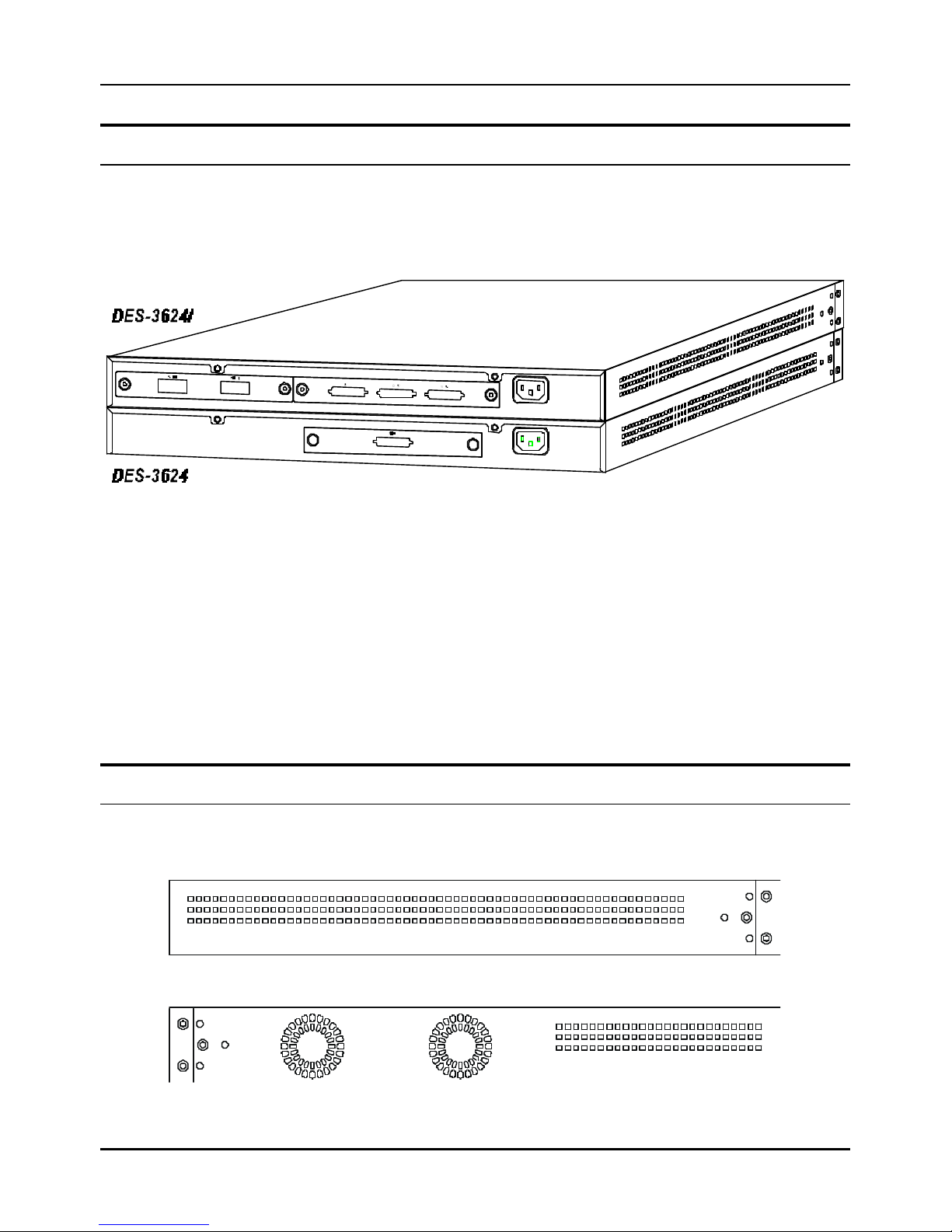
Rear Panel
The rear panel of the DES-3624, DES-3624F, and DES-3624FM consist of a slot (labeled Slot2) for a Stacking input/output
port and an AC power connector. The rear panel of the DES -3624i, DES -3624iF, and DES-3624iFM consist of two slots
(labeled Slot2 and Slot3). Slot2 is for Stacking input/output ports Sio1, Sio2, and Sio3. Slot3 is for an optional Gigabit
Ethernet uplink (MDI-II) port. The following shows the rear panel of the Switches.
Figure 3-2. Rear panel view of the Switches
♦ The optional Gigabit Ethernet slide-in module is an uplink/MDI-II (media dependent interface) port for uplink to
another Switch (DES -3624i, DES-3624iF, and DES -3624iFM only). Two models are available, one-port and two port.
♦ The Stacking input/output port slide-in module in the rear panel is for stacking to another device to implement a
high-port count, manageable Switch. The three-port module is for a master device and a one-port module is for a
client device.
♦ The AC power connector is a three-pronged connector that supports the power cord. Plug in the female connector of
the provided power cord into this connector, and the male into a power outlet. Supported input voltages range from
100 ~ 240 VAC at 50 ~ 60 Hz.
Side Panels
The right side panel of the Switch contains two system fans (see the bottom part of the diagram below). The left side panel
contains heat vents.
Figure 3-3. Side panel views of the Switch
Stackable NWay Ethernet Switch User’s Guide
Identifying External Components 19
♦ The system fans are used to dissipate heat. The sides of the system also provide heat vents to serve the same
purpose. Do not block these openings, and leave adequate space at the rear and sides of the Switch for proper
ventilation. Be reminded that without proper heat dissipation and air circulation, system components might
overheat, which could lead to system failure.
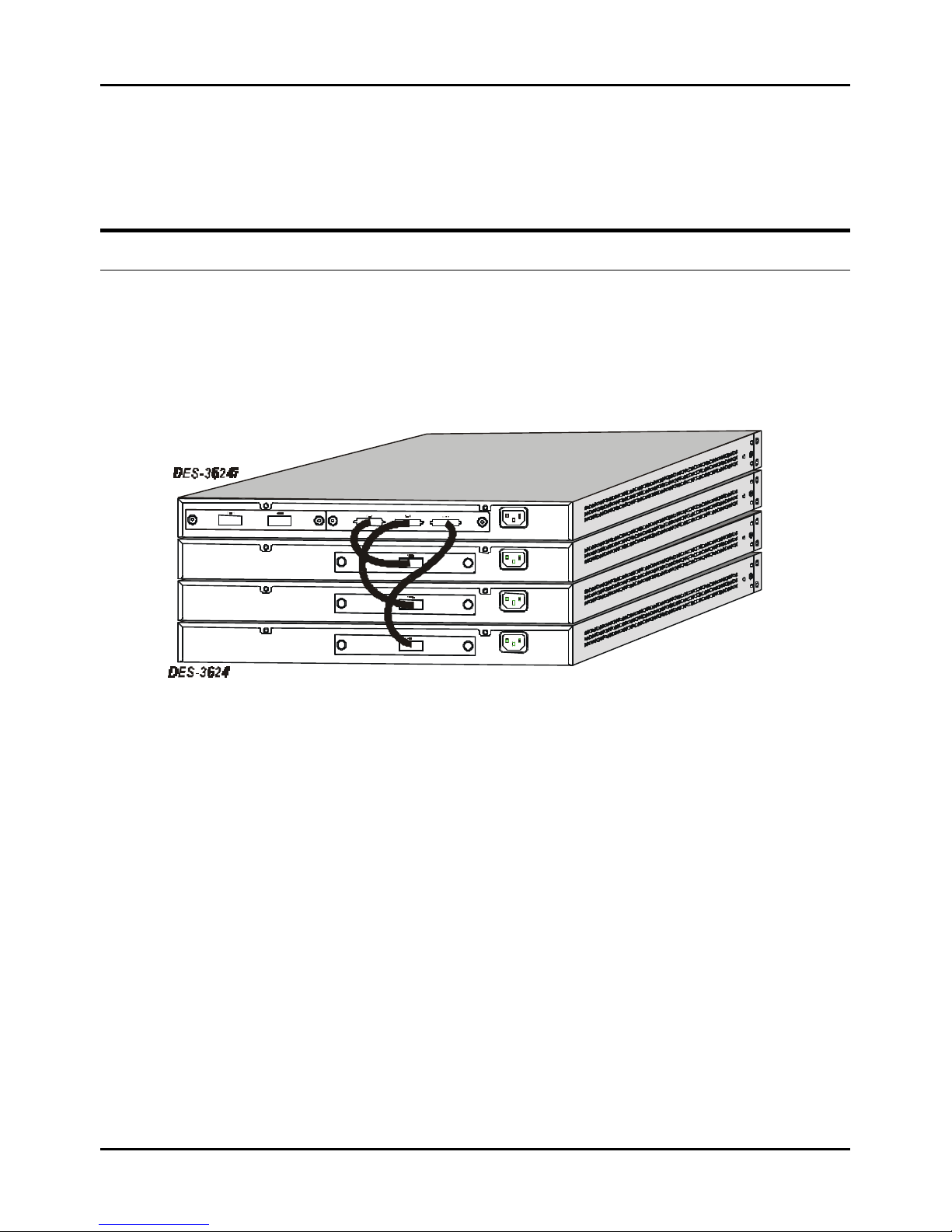
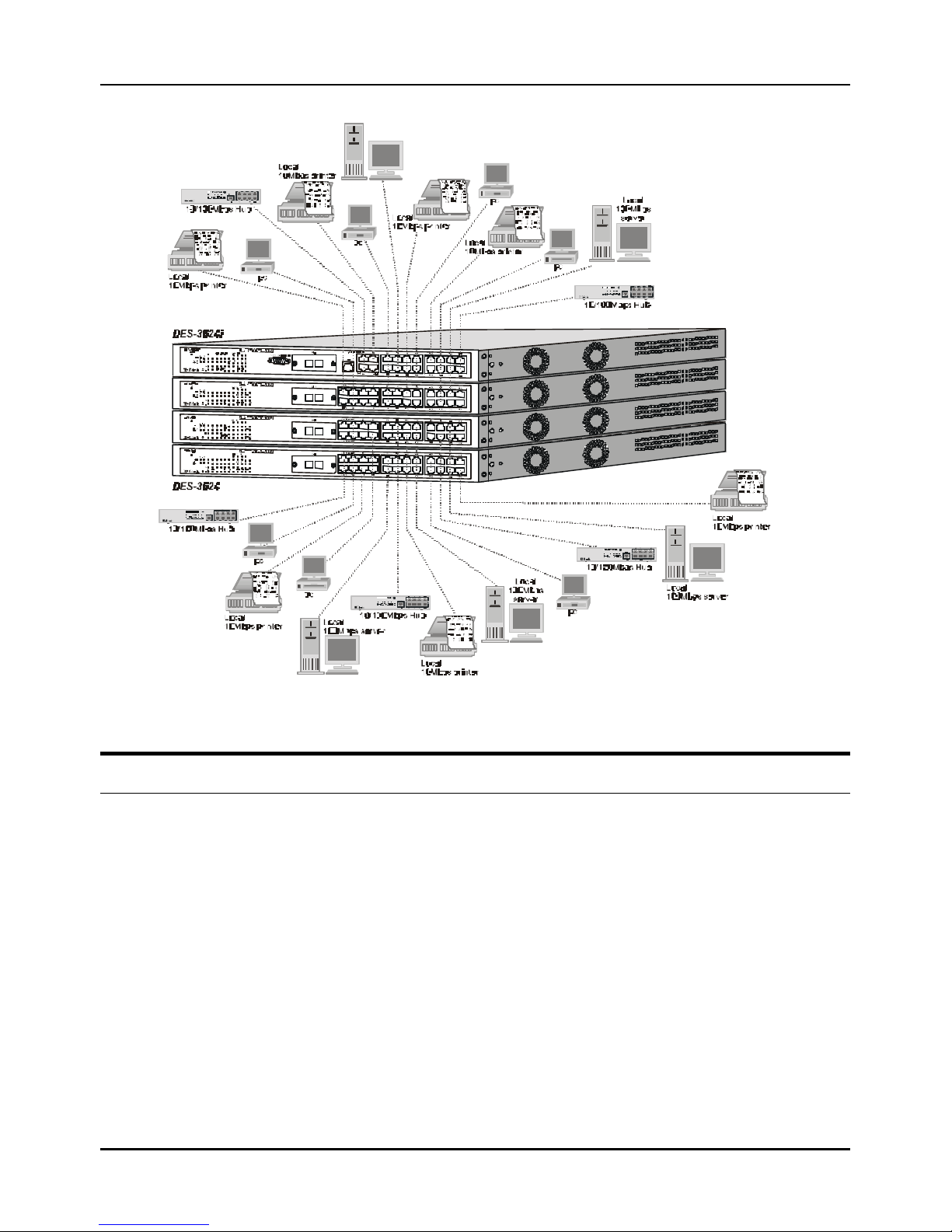
Stack Operation
The DES -3624i, DES-3624iF, and DES -3624iFM are all intelligent Switches capable of acting as a master for up to
three slave Switches (DES -3624, DES-3624F, or DES-3624FM). Each port is referred to by unit ID and port number in
your DES-3624 Series stack.
To set up a stack, a one-port Stacking input/output module is needed for each client Switch and a three-port Stacking
input/output module is needed for the master Switch. Once the modules have been installed, use a cascade cable to
connect each client Switch to the master Switch.
Figure 3-4. Switch stack with one master and three slaves
Please note that two client switches can also be connected via the Stacking input/output ports.
The following diagram displays some possible switch stack connections:
Stackable NWay Ethernet Switch User’s Guide
20 Identi fying External Components
Figure 3-5. Switch stack with example of possible connections
Optional Plug-in Modules
The DES -3624i/DES-3624iF/DES-3624iFM Stackable NWay Ethernet Switch is able to accommodate a range of plug-in
modules in order to increase functionality and performance.
Stackable NWay Ethernet Switch User’s Guide
Identifying External Components 21
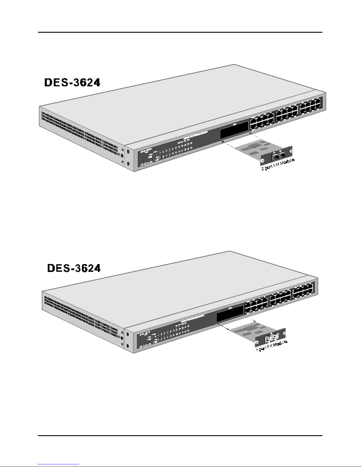
100BASE-FX (MT-RJ) Module
Figure 3-6. Two-port, 100BASE-FX (MT-RJ) module
♦ Two-port, front-panel module.
♦ Connects to 100BASE-FX devices at full- or half-duplex.
♦ Supports multi-mode fiber-optic cable connections of up to 412 meters in half-duplex or 2 km in full-duplex mode.
100BASE-FX (SC) Module
Figure 3-7. One -port, 100BASE-FX (SC) module
♦ One-port, front panel module.
♦ Connects to a 100BASE-FX device at full- or half-duplex.
♦ Supports multi-mode fiber-optic cable connections of up to 412 meters in half-duplex or 2 km in full-duplex mode.
Stackable NWay Ethernet Switch User’s Guide
22 Identifying External Components
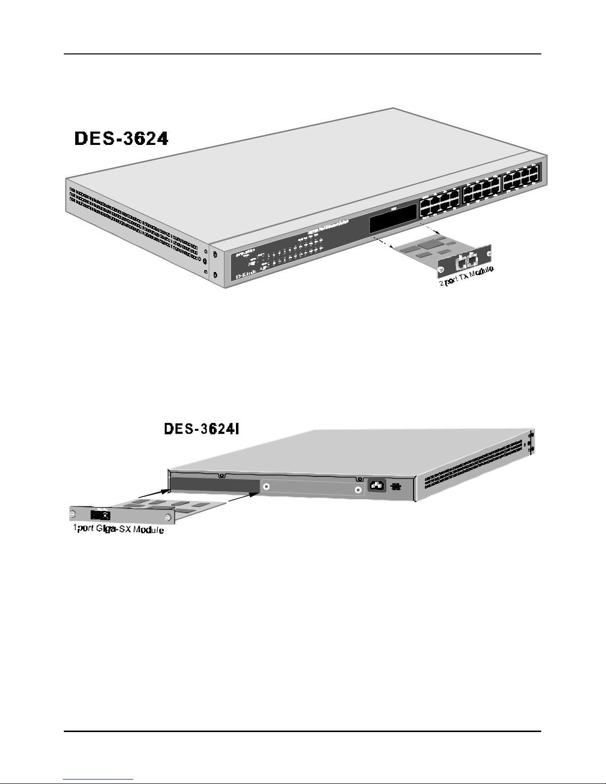
100BASE-TX Module
Figure 3-8. Two-port, 100BASE-TX module
♦ Two-port, front-panel module.
♦ Connects to 100BASE-TX devices at full- or half-duplex.
♦ Supports Category 5 UTP or STP cable connections of up to 100 meters.
1000BASE-SX Gigabit Module
Figure 3-9. One -port, 1000BASE-SX gigabit module
♦ One- or two-port, rear-panel module.
♦ Connects to 1000BASE-SX devices at full duplex.
♦ Allows connections using multi-mode fiber optic cable in the following configurations:
Stackable NWay Ethernet Switch User’s Guide
Identifying External Components 23
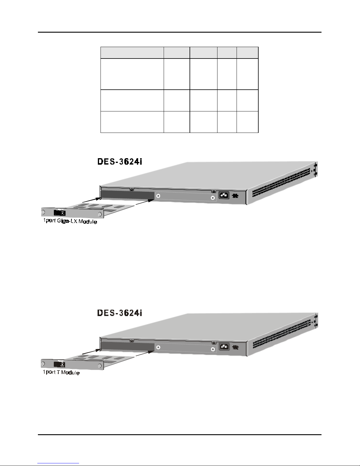
62.5µµm 62.5µµm 50µµm 50µµ m
Modal bandwidth
(min. overfilled launch)
Unit: MHz*km
160 200 400 500
Operating distance
Unit: meters
220 275 500 550
Channel insertion loss
Unit: dB
2.33 2.53 3.25 3.43
1000BASE-LX Gigabit Module
Figure 3-10. One -port, 1000BASE-LX gigabit module
♦ One- or two-port, rear-panel module.
♦ Connects to a 1000BASE-LX device at full duplex.
♦ Allows connections up to 5 km in length using single-mode fiber optic cable.
1000BASE-T Copper Gigabit Module
Figure 3-11. One -port, 1000BASE-T gigabit module
♦ One- or two-port, rear-panel module.
♦ Connects to 1000BASE-T devices at 1000M/full duplex, 100M/full duplex, 100M/half duplex, and Auto.

Stackable NWay Ethernet Switch User’s Guide
24 Identifying External Components
♦ Supports Category 5+ or higher cable connections of up to 100 meters.
LED Indicators
The LED indicators of the Switch include Power, Console, Slot, Giga, Speed, and Link/Act. The following shows the LED
indicators for the Switch along with an explanation of each indicator.
Figure 3-12. The Switch LED indicators
♦ Power This indicator on the front panel should light green after approximately 2 seconds to indicate the ready
state of the Switch when the device is powered on. The LED will blink when the Power-On Self-Test (POST) is
running or if the system’s configuration has changed. This LED will light orange when an error occurs.
♦ Console This indicator is lit green when the switch is being managed via out-of-band/local console management
through the RS-232 console port using a straight -through serial cable. When a secured connection is established,
this LED is lit. The indicator blinks when the console RS-232 is accessed.
♦ Slot2 This indicator is lit green when a slide-in module is present in the rear panel of the Switch.
♦ Slot3 This indicator is lit green when a slide-in module is present in the rear panel of the Switch.
♦ Giga1 This indicator is lit green when a link is established. It blinks green when the Gigabit port is active.
♦ Giga2 This indicator is lit green when a link is established. It blinks green when the Gigabit port is active.
♦ Sio1 This indicator is lit green when a Stacking IO port is present in the rear panel of the Switch.
♦ Sio2 This indicator is lit green when a Stacking IO port is present in the rear panel of the Switch.
♦ Sio3 This indicator is lit green when a Stacking IO port is present in the rear panel of the Switch.

Stackable NWay Ethernet Switch User’s Guide
Identifying External Components 25
♦ 100M These indicators are illuminated green when a 100 Mbps device is connected to any of the 22+2 or 20+2 ports
or uplink port. If a 10 Mbps device is connected to any of the 24 ports or uplink port, these LEDs remain dark. When
a port is active, these indicators will blink green.
♦ Link/Act These indicators are lit when there is a secure connection (or link) to a device at any of the ports. The
LEDs blink whenever there is reception or transmission (i.e. Activity --Act) of data occurring at a port.

Stackable NWay Ethernet Switch User’s Guide
26 Connecting The Switch
44
4 C ONNECTING THE SWITCH
This chapter describes how to connect the Switch to your Ethernet network.
Switch to End Node
End nodes include PCs outfitted with a 10, 100 or 10/100 Mbps RJ-45 Ethernet/Fast Ethernet Network Interface Card
(NIC) and most routers. The RJ-45 UTP ports on NICs and most routers are MDI-II. When using a normal straight-through
cable, an MDI-II port must connect to an MDI-X port.
An end node can be connected to the Switch via a two-pair Category 3, 4, 5 UTP/STP straight cable (be sure to use Category
5 UTP or STP cabling for 100 Mbps Fast Ethernet connections). The end node should be connected to any of the twenty -two
ports (1x - 22x) of the Switch or to either of the two 100BASE-TX ports on the front-panel module that came preinstalled
on the Switch. An end node should not be connected to an Uplink port (unless using a crossover cable), and if the top Uplink
port is in use, Port 1x must remain vacant; if the bottom Uplink port is in use, Port 2x cannot be used.
Figure 4-1. Switch connected to an End Node
The LED indicators for the port the end node is connected to are lit according to the capabilities of the NIC. If LED
indicators are not illuminated after making a proper connection, check the PC’s LAN car d, the cable, switch conditions, and
connections.
The following LED indicator states are possible for an end node to switch connection:
1. The 100M LED indicator comes ON for a 100 Mbps and stays OFF for 10 Mbps.
2. The Link/Act LED indicator lights up upon hooking up a PC that is powered on.
Switch to Hub or Switch
These connections can be accomplished in a number of ways. The most important consideration is that when using a
normal, straight -through cable, the connection should be made between a normal crossed port (Port 1x, 2x, etc.) and an
Uplink (MDI-II) port. If you are using a crossover cable, the connection must be made from Uplink to Uplink, or from a
crossed port to another crossed port.

Stackable NWay Ethernet Switch User’s Guide
Connecting The Switch 27
♦ A 10BASE-T hub or switch can be connected to the Switch via a two-pair Category 3, 4 or 5 UTP/STP straight cable.
♦ A 100BASE-TX hub or switch can be connected to the Switch via a four-pair Category 5 UTP/STP straight cable.
If the other switch or hub contains an unused Uplink port, we suggest connecting the other device’s Uplink (MDI-II) port to
any of the switch’s (MDI-X) ports (1x - 22x, or one of the 100BASE -TX module ports) using a normal straight-through cable,
as shown below.
If the other device does not have an unused Uplink port, make the connection with a normal straight-through cable from
one of the Uplink ports on the switch to any normal crossed port on the hub. Alternatively, if you have a crossover cable you
can save the Uplink ports for other connections and make this one from a crossed port to another crossed port.
Figure 4-2. Switch connected to a normal (non-Uplink) port on a hub or switch using a straight or crossover
cable
10BASE-T Device
For a 10BASE -T device, the Switch’s LED indicators should display the following:
♦ 100M LED speed indicator is OFF.
♦ Link/Act indicator is ON.
100BASE-TX Device
For a 100BASE -TX device, the Switch’s LED indicators should display the following:
♦ 100M LED speed indicator is ON.
♦ Link/Act is ON.

Stackable NWay Ethernet Switch User’s Guide
28 Switch Management Concepts
55
5 S WITCH MANAGEMENT CONCEPTS
This chapter discusses many of the features used to manage the switch, and explains many concepts and important points
regarding these features. Configuring the Switch to implement these concepts is discussed in detail in the next chapters.
Local Console Management
Local console management involves the administration of the Switch via a direct connection to the RS-232 DCE console
port. This is an Out -Of-Band connection, meaning that it is on a different circuit than normal network communications,
and thus works even when the network is down.
The local console mana gement connection involves a terminal or PC running terminal emulation software to operate the
Switch’s built-in console program (see Chapter 6, “Using the Console Interface”). Using the console program, a network
administrator can manage, control and monitor the many functions of the Switch.
Hardware components in the Switch allow it to be an active part of a manageable network. These components include a
CPU, memory for data storage, other related hardware, and SNMP agent firmware. Activities on the Switch can be
monitored with these components, while the Switch can be manipulated to carry out specific tasks.
Diagnostic (Console) Port (RS-232 DCE)
Out-of-band management requires connecting a terminal, such as a VT-100 or a PC running terminal emulation program
(such as HyperTerminal, which is automatically installed with Microsoft Windows) a to the RS-232 DCE console port of
the Switch. Switch management using the RS-232 DCE console port is called Local Console Management to differentiate
it from management done via management platforms, such as D -View, HP OpenView, etc.
The console port is set for the following configuration:
◊ Baud rate: 9,600
◊ Data width: 8 bits
◊ Parity: none
◊ Stop bits: 1
◊ Flow Control none
Make sure the terminal or PC you are using to make this connection is configured to match these settings.
If you are having problems making this connection on a PC, make sure the emulation is set to VT-100 or ANSI. If you
still don’t see anything, try hitting <Ctrl> + r to refresh the screen.

Stackable NWay Ethernet Switch User’s Guide
Switch Management Concepts 29
IP Addresses and SNMP Community Names
Each Switch has its own IP Address, which is used for communication with an SNMP network manager or other TCP/IP
application (for example BOOTP, TFTP). You can change the default Switch IP Address to meet the specification of your
networking address scheme.
In addition, you can also set an IP Address for a gateway router. This becomes necessary when the network management
station is located on a different IP network as the Switch, making it necessary for management packets to go through a
router to reach the network manager, and vice-versa.
For security, you can set in the Switch a list of IP Addresses of the network managers that you allow to manage the Switch.
You can also change the default Community Name in the Switch and set access rights of these Community Names.
Traps
Traps are messages that alert you of events that occur on the Switch. The events can be as serious as a reboot (someone
accidentally turned OFF the Switch), or less serious like a port status change. The Switch generates traps and sends them
to the network manager (trap managers). The following lists the types of events that can take place on the Switch.
◊ System resets
◊ Errors
◊ Status changes
◊ Topology changes
◊ Operation
You can also specify which network managers may receive traps from the Switch by setting a list of IP Addresses of the
authorized network managers.
Trap managers are special users of the network who are given certain rights and access in overseeing the maintenance of
the network. Trap managers will receive traps sent from the Switch; they must immediately take certain actions to avoid
future failure or breakdown of the network.
The following are trap types a trap manager will receive:
♦ Cold Start This trap signifies that the Switch has been powered up and initialized such that software settings
are reconfigured and hardwar e systems are rebooted. A cold start is different from a factory reset.
♦ Warm Start This trap signifies that the Switch has been rebooted, however the Power-On Self-Test (POST) is
skipped.
♦ Authentication Failure This trap signifies that someone has tried to logon to the switch using an invalid
SNMP community name. The switch automatically stores the source IP address of the unauthorized user.
♦ New Root This trap indicates that the Switch has become the new root of the Spanning Tree, the trap is sent by a
bridge soon after its election as the new root. This implies that upon expiration of the Topology Change Timer the
new root trap is sent out immediately after the Switch’s selection as a new root.
♦ Topology Change A Topology Change trap is sent by the Switch when any of its configured ports transitions
from the Learning state to the Forwarding state, or from the Forwarding state to the Blocking state. The trap is not
sent if a new root trap is sent for the same transition.

Stackable NWay Ethernet Switch User’s Guide
30 Switch Management Concepts
♦ Link Change Event This trap is sent whenever the link of a port changes from link up to link down or from link
down to link up.
♦ Port Partition This trap is sent whenever a port is partitioned as a result of more than sixty-one collisions on
the port (i.e., it is automatically partitioned). The number of collisions that triggers this trap is the same at either
10Mbps or 100Mbps.
♦ Broadcast Storm This trap is sent whenever the port reaches the broadcast storm rising or falling threshold.
MIBs
Management information and counters are stored in the Switch in the Management Information Base (MIB). The Switch
uses the standard MIB -II Management Information Base module. Consequently, values for MIB objects can be retrieved
from any SNMP-based network manager software. In addition to the standard MIB -II, the Switch also supports its own
proprietary enterprise MIB as an extended Management Information Base. These MIBs may also be retrieved by
specifying the MIB’s Object-Identity (OID) at the network manager. MIB values can be either read-only or read-write.
Read-only MIBs variables can be either constants that are programmed into the Switch, or variables that change while the
Switch is in operation. Examples of read-only constants are the number of ports and types of ports. Examples of read-only
variables are the statistics counters such as the number of errors that have occurred, or how many kilobytes of data have
been received and forwarded through a port.
Read-write MIBs are variables usually related to user-customized configurations. Examples of these are the Switch’s IP
Address, Spanning Tree Algorithm parameters, and port status.
If you use a third-party vendors’ SNMP software to manage the Switch, a diskette listing the Switch’s propriety enterprise
MIBs can be obtained by request. If your software provides functions to browse or modify MIBs, you can also get the MIB
values and change them (if the MIBs’ attributes permit the write operation). This process however can be quite involved,
since you must know the MIB OIDs and retrieve them one by one.
Packet Forwarding
The Switch learns the network configuration and uses this information to forward packets. This reduces the traffic
congestion on the network, because packets, instead of being transmitted to all segments, are transmitted to the
destination only. Example: if Port 1 receives a packet destined for a station on Port 2, the Switch transmits that packet
through Port 2 only, and transmits nothing through the other ports.
Aging Time
The Aging Time is a parameter that affects the auto-learn process of the Switch in terms of the network configuration.
Dynamic Entries, which make up the auto-learned-node address, are aged out of the address table according to the Aging
Time that you set.
The Aging Time can be from 10 seconds to 9999 seconds. A very long Aging Time can result with the out-of-date Dynamic
Entries that may cause incorrect packet filtering/forwarding decisions.
On the other hand, if the Aging Time is too short, many entries may be aged out soon, resulting in a high percentage of
received packets whose source addresses cannot be found in the address table, in which case the Switch will broadcast the
packet to all ports, negating many of the benefits of having a switch.
 Loading...