

Page 1

Web UI Reference Guide
Product Model:
xStack
Layer 2 Managed Stackable Fast Ethernet Switch
Release 2.6
®
DES-3528/DES-3552 Series
September 2010
Page 2

xStack® DES-3528/DES-3552 Series Layer 2 Stackable Fast Ethernet Manage d Switch Web UI Reference Guide
Information in this document is subject to change without notice.
© 2010 D-Link Corporation. All rights reserved.
Reproduction of this document in any manner whatsoever without the written permission of D-Link Corporation is strictly forbidden.
Trademarks used in this text: D-Link and the D-LINK logo are trademarks of D-Link Corporation; Microsoft and Windows are registered
trademarks of Microsoft Corporation.
Other trademarks and trade names may be used in this document to refer to either the entities claiming the marks and names or their products.
D-Link Corporation disclaims any proprietary interest in trademarks and trade names other than its own.
September 2010 P/N
651ES3500065G
i
Page 3

xStack® DES-3528/DES-3552 Series Layer 2 Stackable Fast Ethernet Manage d Switch Web UI Reference Guide
Table of Contents
Intended Readers ............................................................................................................................. 1
Typographical Conventions ............................................................................................................................................. 1
Notes, Notices and Cautions ........................................................................................................................................... 1
Chapter 1 Web-based Switch Configuration ............................................................................... 2
Introduction ...................................................................................................................................................................... 2
Login to the Web Manager .............................................................................................................................................. 2
Web-based User Interface .............................................................................................................................................. 3
Areas of the User Interface ............................................................................................................................... ........... 3
Web Pages ...................................................................................................................................................................... 4
Chapter 2 System Configuration ................................................................................................. 5
Device Information .......................................................................................................................................................... 5
System Information Settings ........................................................................................................................................... 6
Dual Configuration Settings ............................................................................................................................................ 7
Firmware Information Settings ........................................................................................................................................ 8
Port Configuration ........................................................................................................................................................... 9
Port Settings ................................................................................................................................................................ 9
Port Description Settings ........................................................................................................................................... 10
Port Error Disabled .................................................................................................................................................... 11
Jumbo Frame Settings .............................................................................................................................................. 12
PoE ................................................................................................................................................................................ 12
PoE System Settings ................................................................................................................................................. 13
PoE Port Settings ...................................................................................................................................................... 14
Serial Port Settings ....................................................................................................................................................... 15
System Log configuration .............................................................................................................................................. 16
System Log Settings .................................................................................................................................................. 16
System Log Server Settings ...................................................................................................................................... 17
System Log ................................................................................................................................................................ 17
System Log & Trap Settings ...................................................................................................................................... 18
System Severity Settings ........................................................................................................................................... 19
Time Range Settings ..................................................................................................................................................... 20
Time Settings ................................................................................................................................................................ 20
User Accounts Settings ................................................................................................................................................. 21
Stacking ......................................................................................................................................................................... 22
Stacking Device Table ............................................................................................................................................... 24
Stacking Mode Settings ............................................................................................................................................. 25
Chapter 3 Management ............................................................................................................ 26
ARP ............................................................................................................................................................................... 26
Static ARP Settings ................................................................................................................................................... 26
Proxy ARP Settings ................................................................................................................................................... 27
ARP Table ................................................................................................................................................................. 27
Gratuitous ARP ............................................................................................................................................................. 28
Gratuitous ARP Global Settings ................................................................................................................................ 28
Gratuitous ARP Settings ............................................................................................................................................ 29
ii
Page 4

xStack® DES-3528/DES-3552 Series Layer 2 Stackable Fast Ethernet Manage d Switch Web UI Reference Guide
IPv6 Neighbor Settings ................................................................................................................................................. 29
IP Interface .................................................................................................................................................................... 30
System IP Address Settings ...................................................................................................................................... 30
Interface Settings ....................................................................................................................................................... 31
Management Settings ................................................................................................................................................... 34
Session Table................................................................................................................................................................ 35
Single IP Management .................................................................................................................................................. 35
Single IP Settings ...................................................................................................................................................... 37
Topology .................................................................................................................................................................... 38
Firmware Upgrade ..................................................................................................................................................... 44
Configuration File Backup/Restore ............................................................................................................................ 44
Upload Log File ......................................................................................................................................................... 45
SNMP Settings .............................................................................................................................................................. 45
SNMP Global Settings ............................................................................................................................................... 46
SNMP Traps Settings ................................................................................................................................................ 47
SNMP Linkchange Traps Settings ............................................................................................................................ 47
SNMP View Table Settings ....................................................................................................................................... 48
SNMP Community Table Settings ............................................................................................................................. 49
SNMP Group Table Settings ..................................................................................................................................... 50
SNMP Engine ID Settings ......................................................................................................................................... 51
SNMP User Table Settings ........................................................................................................................................ 52
SNMP Host Table Settings ........................................................................................................................................ 53
SNMPv6 Host Table Settings .................................................................................................................................... 53
RMON Settings .......................................................................................................................................................... 54
Telnet Settings .............................................................................................................................................................. 55
Web Settings ................................................................................................................................................................. 55
Chapter 4 L2 Features .............................................................................................................. 56
VLAN ............................................................................................................................................................................. 56
802.1Q VLAN Settings .............................................................................................................................................. 61
802.1v Protocol VLAN ............................................................................................................................................... 64
Asymmetric VLAN Settings ....................................................................................................................................... 66
GVRP ......................................................................................................................................................................... 66
MAC-based VLAN Settings ....................................................................................................................................... 69
PVID Auto Assign Settings ........................................................................................................................................ 69
Subnet VLAN ............................................................................................................................................................. 70
VLAN Counter Settings ............................................................................................................................................. 72
Voice VLAN ............................................................................................................................................................... 73
VLAN Trunk Settings ................................................................................................................................................. 77
Browse VLAN ............................................................................................................................................................ 78
Show VLAN Ports ...................................................................................................................................................... 78
Q-in-Q ............................................................................................................................................................................ 79
Q-in-Q Settings .......................................................................................................................................................... 79
VLAN Translation Settings ........................................................................................................................................ 80
Layer 2 Protocol Tunneling Settings ............................................................................................................................. 81
Spanning Tree ............................................................................................................................................................... 82
STP Bridge Global Settings ....................................................................................................................................... 85
STP Port Settings ...................................................................................................................................................... 86
iii
Page 5

xStack® DES-3528/DES-3552 Series Layer 2 Stackable Fast Ethernet Manage d Switch Web UI Reference Guide
MST Configuration Identification ............................................................................................................................... 87
STP Instance Settings ............................................................................................................................................... 88
MSTP Port Information .............................................................................................................................................. 89
Link Aggregation ........................................................................................................................................................... 91
Port Trunking Settings ............................................................................................................................................... 92
LACP Port Settings .................................................................................................................................................... 93
FDB ............................................................................................................................................................................... 94
Static FDB Settings ................................................................................................................................................... 94
MAC Notification Settings .......................................................................................................................................... 95
MAC Address Aging Time Settings ........................................................................................................................... 96
MAC Address Table .................................................................................................................................................. 97
ARP & FDB Table ...................................................................................................................................................... 98
L2 Multicast Control ...................................................................................................................................................... 98
IGMP Snooping ......................................................................................................................................................... 98
MLD Snooping ......................................................................................................................................................... 107
Multicast VLAN ........................................................................................................................................................ 116
Multicast Filtering ........................................................................................................................................................ 123
IPv4 Multicast Filtering ............................................................................................................................................ 123
Multicast Filtering Mode ........................................................................................................................................... 126
ERPS Settings............................................................................................................................................................. 127
LLDP ........................................................................................................................................................................... 130
LLDP Global Settings .............................................................................................................................................. 130
LLDP Port Settings .................................................................................................................................................. 131
LLDP Management Address List ............................................................................................................................. 133
LLDP Basic TLVs Settings ...................................................................................................................................... 133
LLDP Dot1 TLVs Settings ........................................................................................................................................ 134
LLDP Dot3 TLVs Settings ........................................................................................................................................ 136
LLDP Statistic System ............................................................................................................................................. 137
LLDP Local Port Information ................................................................................................................................... 137
LLDP Remote Port Information ............................................................................................................................... 139
Chapter 5 L3 Features ............................................................................................................ 140
Local Route Settings ................................................................................................................................................... 140
IPv4 Static/Default Route Settings .............................................................................................................................. 140
IPv4 Route Table ........................................................................................................................................................ 141
IPv6 Static/Default Route Settings .............................................................................................................................. 142
IPv6 Route Table ........................................................................................................................................................ 142
Policy Route Settings .................................................................................................................................................. 143
IP Forwarding Table .................................................................................................................................................... 144
Chapter 6 QoS ........................................................................................................................ 145
802.1p Settings ........................................................................................................................................................... 147
802.1p Default Priority Settings ............................................................................................................................... 147
802.1p User Priority Settings ................................................................................................................................... 148
802.1p Map Settings ................................................................................................................................................ 149
Bandwidth Control ....................................................................................................................................................... 150
Bandwidth Control Settings ..................................................................................................................................... 150
Queue Bandwidth Control Settings ......................................................................................................................... 151
Traffic Control Settings ................................................................................................................................................ 152
iv
Page 6

xStack® DES-3528/DES-3552 Series Layer 2 Stackable Fast Ethernet Manage d Switch Web UI Reference Guide
DSCP .......................................................................................................................................................................... 155
DSCP Trust Settings ............................................................................................................................................... 155
DSCP Map Settings ................................................................................................................................................. 156
HOL Blocking Prevention ............................................................................................................................................ 158
Scheduling Settings .................................................................................................................................................... 159
QoS Scheduling ....................................................................................................................................................... 159
QoS Scheduling Mechanism ................................................................................................................................... 160
SRED .......................................................................................................................................................................... 162
SRED Settings ......................................................................................................................................................... 162
SRED Drop Counter ................................................................................................................................................ 164
Chapter 7 ACL ........................................................................................................................ 165
ACL Configuration Wizard ........................................................................................................................................... 165
Access Profile List ....................................................................................................................................................... 166
Add an Ethernet ACL Profile ................................................................................................................................... 167
Adding an IPv4 ACL Profile ..................................................................................................................................... 171
Adding an IPv6 ACL Profile ..................................................................................................................................... 176
Adding a Packet Content ACL Profile ..................................................................................................................... 179
CPU Access Profile List .............................................................................................................................................. 184
Adding a CPU Ethernet ACL Profile ........................................................................................................................ 185
Adding a CPU IPv4 ACL Profile .............................................................................................................................. 188
Adding a CPU IPv6 ACL Profile .............................................................................................................................. 192
Adding a CPU Packet Content ACL Profile ............................................................................................................. 195
ACL Finder .................................................................................................................................................................. 198
ACL Flow Meter........................................................................................................................................................... 199
Chapter 8 Security .................................................................................................................. 202
802.1X ......................................................................................................................................................................... 202
802.1X Global Settings ............................................................................................................................................ 205
802.1X Port Settings ................................................................................................................................................ 206
802.1X User Settings ............................................................................................................................................... 207
Guest VLAN Settings ............................................................................................................................................... 208
Authenticator State .................................................................................................................................................. 209
Authenticator Statistics ............................................................................................................................................ 210
Authenticator Session Statistics .............................................................................................................................. 211
Authenticator Diagnostics ........................................................................................................................................ 212
Initialize Port(s) ........................................................................................................................................................ 213
Reauthenticate Port(s) ............................................................................................................................................. 214
RADIUS ....................................................................................................................................................................... 215
Authentication RADIUS Server Settings ................................................................................................................. 215
RADIUS Accounting Settings .................................................................................................................................. 216
RADIUS Authentication ........................................................................................................................................... 216
RADIUS Account Client ........................................................................................................................................... 218
IP-MAC-Port Binding (IMPB) ....................................................................................................................................... 220
IMPB Global Settings .............................................................................................................................................. 220
IMPB Port Settings .................................................................................................................................................. 221
IMPB Entry Settings ................................................................................................................................................ 222
MAC Block List ........................................................................................................................................................ 223
DHCP Snooping ...................................................................................................................................................... 223
v
Page 7

xStack® DES-3528/DES-3552 Series Layer 2 Stackable Fast Ethernet Manage d Switch Web UI Reference Guide
ND Snooping ........................................................................................................................................................... 225
MAC-based Access Control (MAC)............................................................................................................................. 227
MAC-based Access Control Settings ...................................................................................................................... 227
MAC-based Access Control Local Settings ............................................................................................................. 229
MAC-based Access Control Authentication State ................................................................................................... 230
Web-based Access Control (WAC) ............................................................................................................................. 231
WAC Global Settings ............................................................................................................................................... 233
WAC User Settings .................................................................................................................................................. 234
WAC Port Settings ................................................................................................................................................... 235
WAC Authentication State ....................................................................................................................................... 236
Japanese Web-based Access Control (JWAC) .......................................................................................................... 236
JWAC Global Settings ............................................................................................................................................. 236
JWAC Port Settings ................................................................................................................................................. 238
JWAC User Settings ................................................................................................................................................ 240
JWAC Authentication State ..................................................................................................................................... 240
JWAC Customize Page Language .......................................................................................................................... 241
JWAC Customize Page ........................................................................................................................................... 242
Compound Authentication ........................................................................................................................................... 243
Compound Authentication Settings ......................................................................................................................... 244
Compound Authentication Guest VLAN Settings .................................................................................................... 246
Port Security ................................................................................................................................................................ 247
Port Security Settings .............................................................................................................................................. 247
Port Security VLAN Settings .................................................................................................................................... 248
Port Security Entries ................................................................................................................................................ 249
ARP Spoofing Prevention Settings ............................................................................................................................. 249
BPDU Attack Protection .............................................................................................................................................. 250
Loopback Detection Settings ...................................................................................................................................... 252
Traffic Segmentation Settings ..................................................................................................................................... 253
NetBIOS Filtering Settings .......................................................................................................................................... 254
DHCP Server Screening ............................................................................................................................................. 255
DHCP Server Screening Port Settings .................................................................................................................... 255
DHCP Offer Permit Entry Settings........................................................................................................................... 256
Access Authentication Control .................................................................................................................................... 256
Enable Admin .......................................................................................................................................................... 257
Authentication Policy Settings ................................................................................................................................. 258
Application Authentication Settings ......................................................................................................................... 259
Authentication Server Group Settings ..................................................................................................................... 259
Authentication Server Settings ................................................................................................................................ 261
Login Method Lists Settings .................................................................................................................................... 262
Enable Method Lists Settings .................................................................................................................................. 263
Local Enable Password Settings ............................................................................................................................. 264
SSL Settings................................................................................................................................................................ 265
SSH ............................................................................................................................................................................. 267
SSH Settings ........................................................................................................................................................... 267
SSH Authentication Method and Algorithm Settings ............................................................................................... 268
SSH User Authentication List .................................................................................................................................. 270
Trusted Host Settings .................................................................................................................................................. 271
vi
Page 8

xStack® DES-3528/DES-3552 Series Layer 2 Stackable Fast Ethernet Manage d Switch Web UI Reference Guide
Safeguard Engine Settings ......................................................................................................................................... 272
Chapter 9 Network Application ............................................................................................... 275
DHCP .......................................................................................................................................................................... 275
DHCP Relay ............................................................................................................................................................ 275
DHCP Server ........................................................................................................................................................... 281
DHCPv6 Relay ........................................................................................................................................................ 285
DHCP Local Relay Settings ..................................................................................................................................... 287
DNS ............................................................................................................................................................................. 287
DNS Relay ............................................................................................................................................................... 287
PPPoE Circuit ID Insertion Settings ............................................................................................................................ 289
SNTP ........................................................................................................................................................................... 290
SNTP Settings ......................................................................................................................................................... 290
Time Zone Settings ................................................................................................................................................. 291
Chapter 10 OAM ....................................................................................................................... 293
CFM ............................................................................................................................................................................. 293
CFM Settings ........................................................................................................................................................... 293
CFM Port Settings ................................................................................................................................................... 298
CFM Loopback Settings .......................................................................................................................................... 299
CFM Linktrace Settings ........................................................................................................................................... 300
CFM Packet Counter ............................................................................................................................................... 300
CFM Fault Table ...................................................................................................................................................... 301
CFM MP Table ........................................................................................................................................................ 302
Ethernet OAM.............................................................................................................................................................. 302
Ethernet OAM Settings ............................................................................................................................................ 302
Ethernet OAM Configuration Settings ..................................................................................................................... 303
Ethernet OAM Event Log ......................................................................................................................................... 305
Ethernet OAM Statistics .......................................................................................................................................... 305
DULD Settings............................................................................................................................................................. 306
Cable Diagnostics ....................................................................................................................................................... 307
Chapter 11 Monitoring .............................................................................................................. 309
Utilization ..................................................................................................................................................................... 309
CPU Utilization......................................................................................................................................................... 309
DRAM & Flash Utilization ........................................................................................................................................ 310
Port Utilization ......................................................................................................................................................... 310
Statistics ...................................................................................................................................................................... 311
Port Statistics ........................................................................................................................................................... 311
Packet Size .............................................................................................................................................................. 320
VLAN Counter Statistics .......................................................................................................................................... 322
Mirror ........................................................................................................................................................................... 323
Port Mirror Settings .................................................................................................................................................. 323
RSPAN Settings ...................................................................................................................................................... 324
sFlow ........................................................................................................................................................................... 325
sFlow Global Settings .............................................................................................................................................. 325
sFlow Analyzer Server Settings............................................................................................................................... 326
sFlow Flow Sampler Settings .................................................................................................................................. 326
sFlow Counter Poller Settings ................................................................................................................................. 327
vii
Page 9

xStack® DES-3528/DES-3552 Series Layer 2 Stackable Fast Ethernet Manage d Switch Web UI Reference Guide
Ping Test ..................................................................................................................................................................... 328
Trace Route ................................................................................................................................................................. 329
Peripheral .................................................................................................................................................................... 331
Device Status........................................................................................................................................................... 331
Chapter 12 Save and Tools ...................................................................................................... 332
Save Configuration ID 1 .............................................................................................................................................. 332
Save Configuration ID 2 .............................................................................................................................................. 332
Save Log ..................................................................................................................................................................... 333
Save All ....................................................................................................................................................................... 333
Stacking Information ................................................................................................................................................... 333
Download Firmware .................................................................................................................................................... 335
Download Configuration File ....................................................................................................................................... 335
Upload Configuration File ............................................................................................................................................ 336
Upload Log File ........................................................................................................................................................... 337
Reset ........................................................................................................................................................................... 338
Reboot System ............................................................................................................................................................ 338
Appendix A Mitigating ARP Spoofing Attacks Using Packet Content ACL ................................ 339
How Address Resolution Protocol works .................................................................................................................... 339
How ARP Spoofing Attacks a Network ....................................................................................................................... 341
Prevent ARP Spoofing via Packet Content ACL ......................................................................................................... 342
Configuration ............................................................................................................................................................... 342
Appendix B System Log and Trap List ...................................................................................... 345
System Log Entries ..................................................................................................................................................... 345
DES-3528/DES-3552 Series Trap List ........................................................................................................................ 353
Proprietary Trap List .................................................................................................................................................... 353
Appendix C Password Recovery Procedure .............................................................................. 356
Appendix D Glossary ................................................................................................................. 357
viii
Page 10

xStack® DES-3528/DES-3552 Series Layer 2 Stackable Fast Ethernet Manage d Switch Web UI Reference Guide
Intended Readers
Typographical Conventions
Notes, Notices and Cautions
Safety Instructions
General Precautions for Rack-Mountable Products
Protecting Against Electrostatic Discharge
The DES-3528/DES-3552 Series Web UI Reference Guide contains information for setu p and management of the
Switch. This manual is intended for network managers familiar with network m anagement concepts and terminology.
Typographical Conventions
Convention Description
[ ] In a command line, square brackets indicate an optional entry. For example: [copy
filename] means that optionally you can type copy followed by the name of the file. Do
not type the brackets.
Bold font
Boldface Typewriter
Font
Initial capital letter Indicates a window name. Names of keys on the keyboard have initial capitals. For
Menu Name > Menu
Option
Indicates a button, a toolbar icon, menu, or menu item. For example: Open the File
menu and choose Cancel. Used for emphasis. May also indicate system messages or
prompts appearing on screen. For example: You have mail. Bold font is also used to
represent filenames, program names and commands. For example: use the copy
command.
Indicates commands and responses to prompts that must be typed exactly as printed in
the manual.
example: Click Enter.
Menu Name > Menu Option Indicates the menu structure. Device > Port > Port
Properties means the Port Properties menu option under the Port menu option that is
located under the Device menu.
Notes, Notices and Cautions
A NOTE indicates important information that helps make better use of the device.
A NOTICE indicates either potential damage to hardware or loss of data and tells how to avoid the
problem.
A CAUTION indicates a potential for property damage, personal injury, or death.
1
Page 11
xStack® DES-3528/DES-3552 Series Layer 2 Stackable Fast Ethernet Manage d Switch Web UI Reference Guide
Chapter 1 Web-based Switch Configuration
Introduction
Login to the Web Manager
Web-based User Interface
Web Pages
Introduction
All software functions of the Switch can be managed, configured and monitored via the embedded web-based (HTML)
interface. The Switch can be managed from remote stations anywhere on the network through a standard browser
such as Firefox, Safari, or Microsoft Internet Explorer. The browser acts as a universal access tool and can
communicate directly with the Switch using the HTTP protocol.
The Web-based management module and the Console program (and Telnet) are different ways to access the same
internal switching software and configure it. Thus, all settings encountered in web-based management are the same as
those found in the console program.
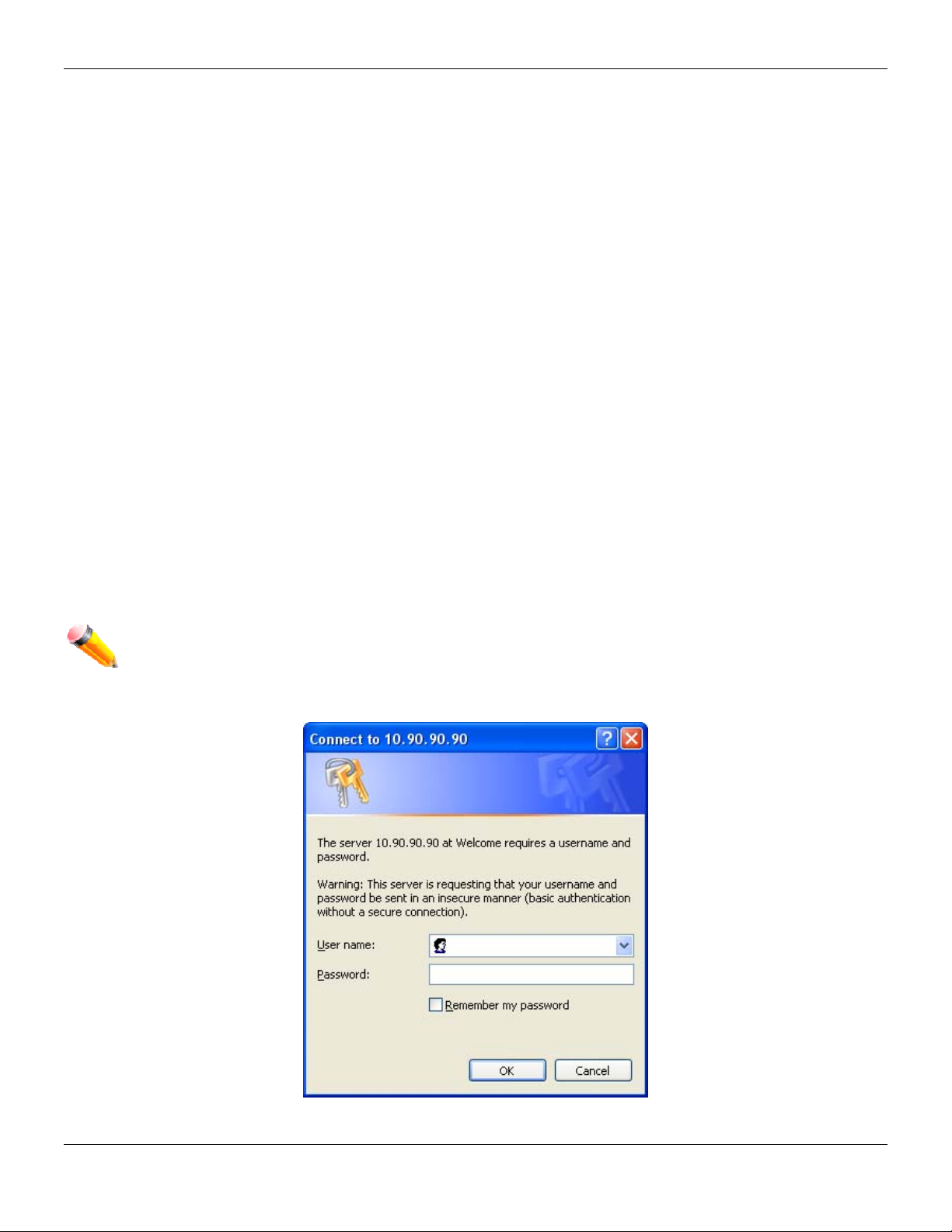
Login to the Web Manager
To begin managing the Switch, simply run the browser installed on your computer and point it to the IP address you
have defined for the device. The URL in the address bar should read something like: http://123.123.123.123, where the
numbers 123 represent the IP address of the Switch.
NOTE: The factory default IP address is 10.90.90.90.
This opens the management module's user authentication window, as seen below.
Figure 1-1 Enter Network Password window
2
Page 12
xStack® DES-3528/DES-3552 Series Layer 2 Stackable Fast Ethernet Manage d Switch Web UI Reference Guide
Leave both the User Name field and the Password field blank and click OK. This will open the Web-based user
interface. The Switch management features available in the Web-based manager are explained below.
Web-based User Interface
The user interface provides access to various Switch configuration and management windows, allows you to view
performance statistics, and permits you to graphically monitor the system status.
Areas of the User Interface
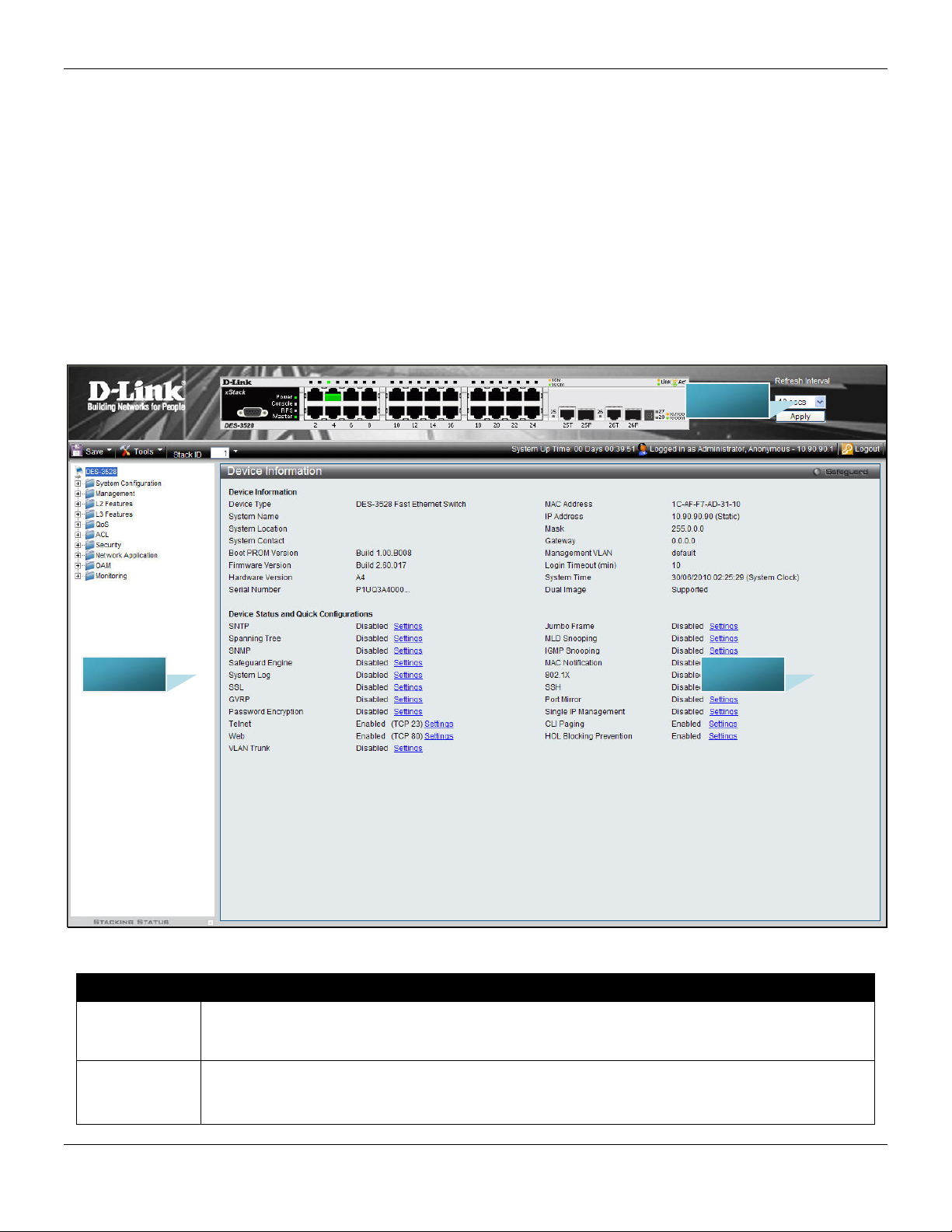
The figure below shows the user interface. Three distinct areas divide the user interface, as described in the table.
AREA 2
AREA 1
Area Number Function
Select the menu or window to display. Open folders and click the hyperlinked menu buttons
Area 1
Area 2
and subfolders contained within them to display menus. Click the D-Link logo to go to the DLink Website.
Presents a graphical near real-time image of the front panel of the Switch. This area displays
the Switch's ports, console and management port, showing port activity.
Some management functions, including save, reboot, download and upload are accessible
AREA 3
Figure 1-2 Main Web-Manager page
3
Page 13

xStack® DES-3528/DES-3552 Series Layer 2 Stackable Fast Ethernet Manage d Switch Web UI Reference Guide
here.
Area 3
Presents switch information based on user selection and the entry of configuration data.
Web Pages
When connecting to the management mode of the Switch with a Web browser, a login screen is displayed. Enter a
user name and password to access the Switch's management mode.
Below is a list of the main folders available in the Web interface:
System Configuration - In this section the user will be able to configure features regarding the Switch’s configuration.
Management - In this section the user will be able to configure features regarding the Switch’s management.
L2 Features - In this section the user will be able to configure features regarding the Layer 2 functionality of the Switch.
L3 Features - In this section the user will be able to configure features regarding the Layer 3 functionality of the Switch.
QoS - In this section the user will be able to configure features regarding the Quality of Service functionality of the
Switch.
ACL - In this section the user will be able to configure features regarding the Access Control List functionality of the
Switch.
Security - In this section the user will be able to configure features regarding the Switch’s security.
Network Application - In this section the user will be able to configure features regarding network applications
handled by the Switch.
OAM - In this section the user will be able to configure features regarding the Switch’s Object Access Method
Monitoring - In this section the user will be able to monitor the Switch’s configuration and statistics.
NOTE: Be sure to configure the user name and password in the User Accounts menu before
connecting the Switch to the greater network.
4
Page 14

xStack® DES-3528/DES-3552 Series Layer 2 Stackable Fast Ethernet Manage d Switch Web UI Reference Guide
Chapter 2 System Configuration
Device Information
System Information Settings
Dual Configuration Settings
Firmware Information Settings
Port Configuration
PoE
Serial Port Settings
System Log configuration
Time Range Settings
Time Settings
User Accounts Settings
Stacking
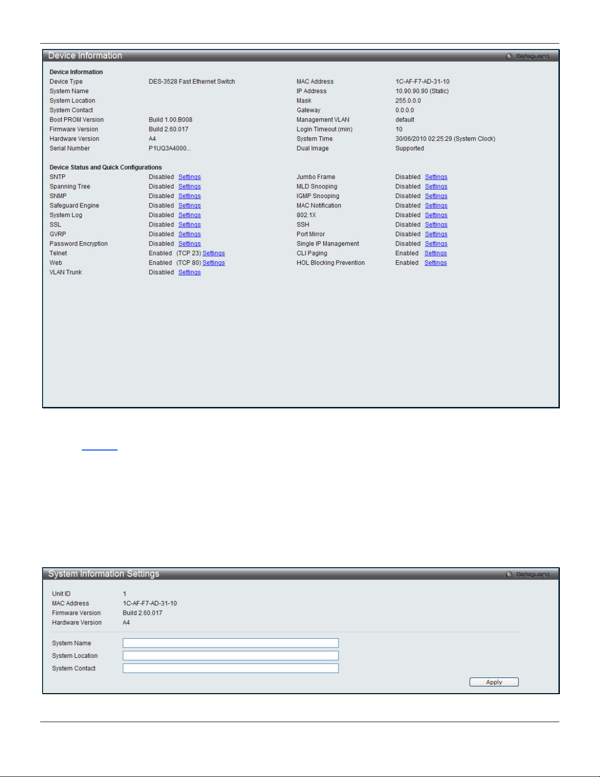
Device Information
This window contains the main settings for all the major functions for the Switch. It appears automatically when you log
on to the Switch. To return to the Device Information window after viewing other windows, click the DES-3528/DES-
3552 Series link.
The Device Information window shows the Switch’s MAC Address (assigned b y the factory and unchangeable), the
Boot PROM Version, Firmware Version, Hardware Version, and many other important types of information. This is
helpful to keep track of PROM and firmware updates and to obtain the Switch’s MAC address for entry into another
network device’s address table, if necessary. In addition, this window displays the status of functions on the Switch to
quickly assess their current global status.
Many functions are hyper-linked for easy access to enable quick configuration from this window.
5
Page 15
xStack® DES-3528/DES-3552 Series Layer 2 Stackable Fast Ethernet Manage d Switch Web UI Reference Guide
Figure 2-1 Device Information window
Click the Settings
link to navigate to the appropriate feature page for configuration.
System Information Settings
The user can enter a System Name, System Location, and System Contact to aid in defining the Switch. This window
also displays the MAC Address, Firmware Version and Hardware Version.
To view the following window, click System Configuration > System Information Settings, as shown below:
Figure 2-2 System Information Settings window
6
Page 16
xStack® DES-3528/DES-3552 Series Layer 2 Stackable Fast Ethernet Manage d Switch Web UI Reference Guide
The fields that can be configured are described below:
Parameter Description
System Name
System Location
System Contact
Click the Apply button to implement changes made.
Enter a system name for the Switch, if so desired. This name will identify it in the Switch
network.
Enter the location of the Switch, if so desired.
Enter a contact name for the Switch, if so desired.
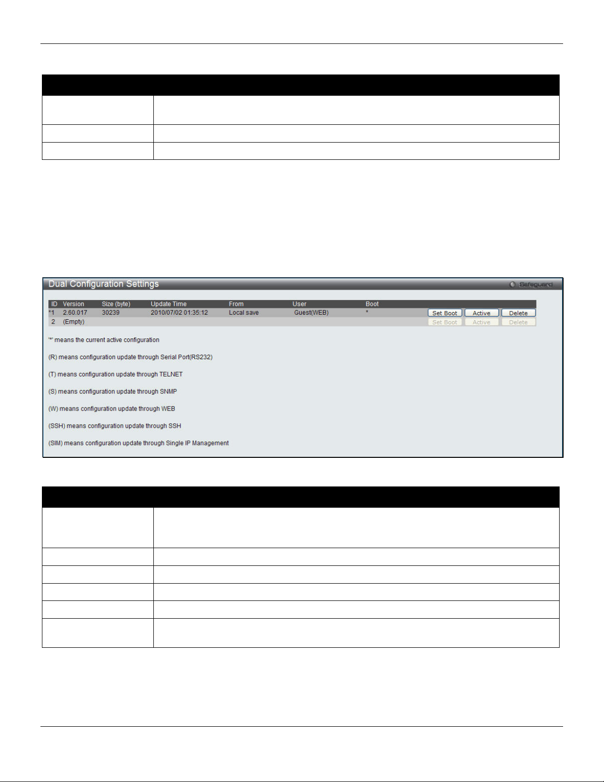
Dual Configuration Settings
The following window is used to manage configuration information in the Switch. The DES-3528/DES-3552 Series has
the capability to store two firmware images in its memory.
To access this table, click System Configuration > Dual Configuration Settings, as shown below:
Figure 2 - 1 Dual Configuration Settings
This window holds the following information:
Parameter Description
ID
Version
Size (Bytes)
Update Time
From
User
Click the corresponding Set Boot button to use the configuration file as the boot up firmware for the Switch. This will
apply upon the next reboot of the Switch.
Click the Active button to enable the configuration file settings.
Click the corresponding Delete button to remove this configuration file from the Switch’s memory.
State the ID number of the configuration file located in the Switch’s memory. The Switch
can store two configuration files for use. ID 1 will be the default boot up configuration file
for the Switch unless otherwise configured by the user.
Display the firmware version that has been saved or uploaded in the Switch.
Display the size of the configuration file, in bytes.
Display the time that the configuration file was updated to the Switch.
Display the location from which the configuration file was uploaded.
Display the name of the user (device) that updated this configuration file. Unknown users
will be displayed as Anonymous.
7
Page 17
xStack® DES-3528/DES-3552 Series Layer 2 Stackable Fast Ethernet Manage d Switch Web UI Reference Guide
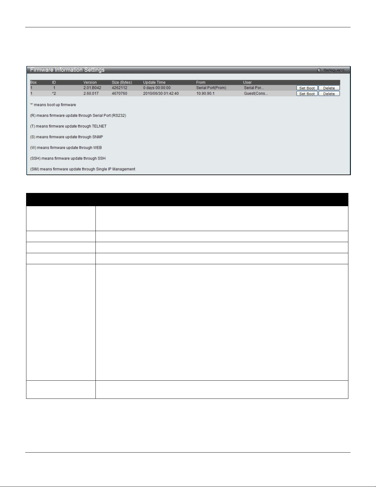
Firmware Information Settings
The following screen allows the user to view information about current firmware images stored on the Switch.
To access this table, click System Configuration > Firmware Information Settings
Figure 2 - 2 Firmware Information window
This window holds the following information:
Parameter Description
ID States the image ID number of the firmware in the Switch’s memory. The Switch can store
two firmware images for use. Image ID 1 will be the default boot up firmware for the
Switch unless otherwise configured by the user.
Version States the firmware version.
Size (Bytes) States the size of the corresponding firmware, in bytes.
Update Time States the specific time the firmware version was downloaded to the Switch.
From States the IP address of the origin of the firmware. There are five ways firmware may be
downloaded to the Switch.
• R – If the IP address has this letter attached, it denotes a firmware upgrade
through the serial port RS232.
• T - If the IP address has this letter attached to it, it denotes a firmware upgrade
through Telnet.
• S - If the IP address has this letter attached to it, it denotes a firmware upgrade
through the Simple Network Management Protocol (SNMP).
• W - If the IP address has this letter attached to it, it denotes a firmware upgrade
through the web-based management interface.
• SSH – If the IP address has these three letters attached, it denotes a firmware
update through SSH.
• SIM – If the IP address has these letters attached, it denotes a firmware upgrade
through the Single IP Management feature.
User States the user who downloaded the firmware. This field may read “Anonymous” or
“Unknown” for users that are unidentified.
Click the corresponding Set Boot button to use this configuration file as the boot up firmware for the Switch. This will
apply upon the next reboot of the Switch.
Click the corresponding Delete button to remove this configuration file from the Switch’s memory.
8
Page 18
xStack® DES-3528/DES-3552 Series Layer 2 Stackable Fast Ethernet Manage d Switch Web UI Reference Guide
Port Configuration
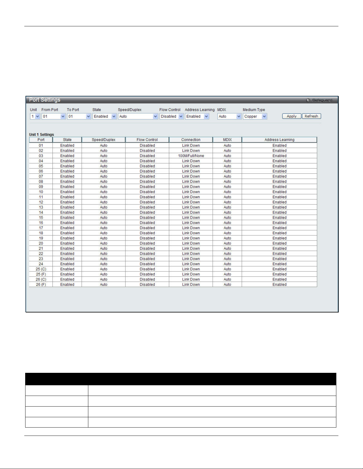
Port Settings
This page used to configure the details of the switch ports. To view the following window, click System Configuration
> Port Configuration > Port Settings, as shown below:
Figure 2-3 Port Settings window
To configure switch ports:
1. Choose the port or sequential range of ports using the From Port and To Port pull-down menus.
2. Use the remaining pull-down menus to configure the parameters described below:
The fields that can be configured are described below:
Parameter Description
Unit
From Port / To Port
State
Speed/Duplex
Select the unit to configure.
Select the appropriate port range used for the configuration here.
Toggle the State field to either enable or disable a given port or group of ports.
Toggle the Speed/Duplex field to select the speed and full-duplex/half-duplex state of the
9
Page 19

xStack® DES-3528/DES-3552 Series Layer 2 Stackable Fast Ethernet Manage d Switch Web UI Reference Guide
port. Auto denotes auto-negotiation among 10, 100 and 1000 Mbps devices, in full- or halfduplex (except 1000 Mbps which is always full duplex). The Auto setting allows the port to
automatically determine the fastest settings the device the port is connected to can handle,
and then to use those settings. The other options are 10M Half, 10M Full, 100M Half, 100M
Full, 1000M Full_Master, 1000M Full_Slave, and 1000M Full. There is no automatic
adjustment of port settings with any option other than Auto.
The Switch allows the user to configure three types of gigabit connections; 1000M
Full_Master, 1000M Full_Slave, and 1000M Full. Gigabit connections only support full
duplex connections and take on certain characteristics that are different from the other
choices listed.
The 1000M Full_Master and 1000M Full_Slave parameters refer to connections running a
1000BASE-T cable for connection between the Switch port and other device capable of a
gigabit connection. The master setting (1000M Full_Master) will allow the port to advertise
capabilities related to duplex, speed and physical layer type. The master setting will also
determine the master and slave relationship between the two connected physical layers.
This relationship is necessary for establishing the timing control between the two physical
layers. The timing control is set on a master physical layer by a local source. The slave
setting (1000M Full_Slave) uses loop timing, where the timing comes from a data stream
received from the master. If one connection is set for 1000M Full_Master, the other side of
the connection must be set for 1000M Full_Slave. Any other configuration will result in a link
down status for both ports.
Flow Control
Address Learning
MDIX
Medium Type
Click the Apply button to implement changes made.
Click the Refresh button to update the display section of this page.
Displays the flow control scheme used for the various port configurations. Ports configured
for full-duplex use 802.3x flow control, half-duplex ports use backpressure flow control, and
Auto ports use an automatic selection of the two. The default is Disabled.
Enable or disable MAC address learning for the selected ports. When Enabled, destination
and source MAC addresses are automatically listed in the forwarding table. When address
learning is Disabled, MAC addresses must be manually entered into the forwarding table.
This is sometimes done for reasons of security or efficiency. See the section on
Forwarding/Filtering for information on entering MAC addresses into the forwarding table.
The default setting is Enabled.
Auto - Select auto for auto sensing of the optimal type of cabling.
Normal - Select normal for normal cabling. If set to normal state, the port is in MDI mode
and can be connected to a PC NIC using a straight-through cable or a port (in MDI mode)
on another switch through a cross-over cable.
Cross - Select cross for cross cabling. If set to cross state, the port is in MDIX mode, and
can be connected to a port (in MDI mode) on another switch throug h a straight cable.
If configuring the Combo ports, this defines the type of transport medium to be used.
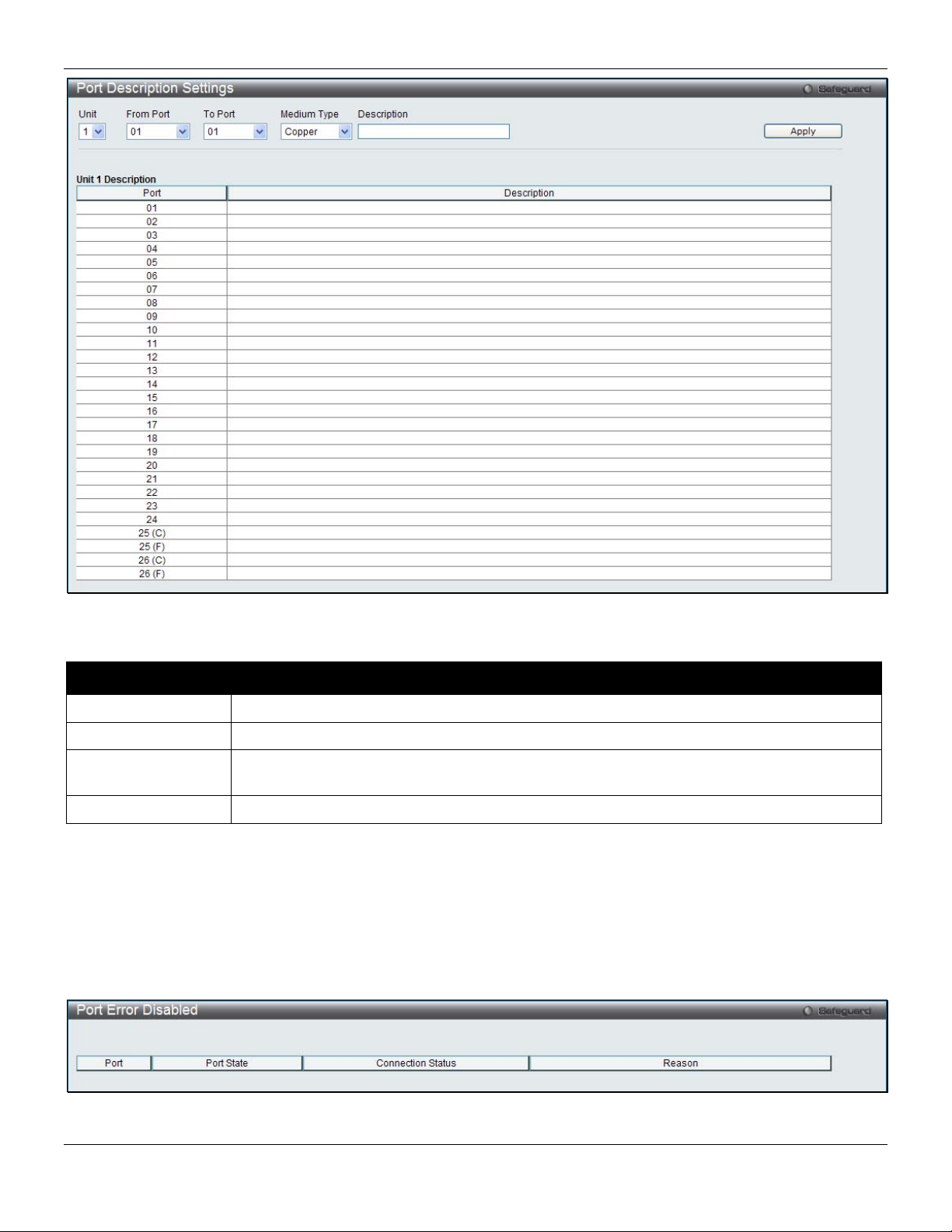
Port Description Settings
The Switch supports a port description feature where the user may name various ports.
To view the following window, click System Configuration > Port Configuration > Port Description Settings, as
shown below:
10
Page 20
xStack® DES-3528/DES-3552 Series Layer 2 Stackable Fast Ethernet Manage d Switch Web UI Reference Guide
Figure 2-4 Port Description Settings window
The fields that can be configured are described below:
Parameter Description
Unit
From Port / To Port
Medium Type
Description
Click the Apply button to implement changes made.
Select the unit to configure.
Select the appropriate port range used for the configuration here.
Specify the medium type for the selected ports. If configuring the Combo ports, the Medium
Type defines the type of transport medium to be used, whether Copper or Fiber.
Users may then enter a description for the chosen port(s).
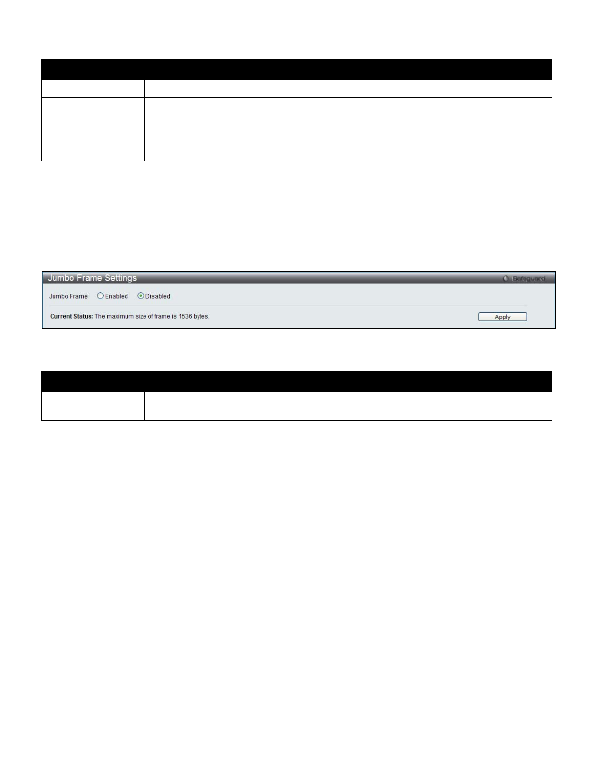
Port Error Disabled
The following window displays the information about ports that have been disconnected by the Switch when a packet
storm occurs or a loop was detected.
To view the following window, click System Configuration > Port Configuration > Port Error Disabled, as shown
below:
Figure 2-5 Port Error Disabled window
11
Page 21
xStack® DES-3528/DES-3552 Series Layer 2 Stackable Fast Ethernet Manage d Switch Web UI Reference Guide
The fields that can be displayed are described below:
Parameter Description
Port
Port State
Connection Status
Reason
Display the port that has been error disabled.
Describe the current running state of the port, whether enabled or disabled.
Display the uplink status of the individual ports, whether enabled or disabled.
Describe the reason why the port has been error-disabled, such as it has become a
shutdown port for storm control.
Jumbo Frame Settings
The Switch supports jumbo frames. Jumbo frames are Ethernet frames with more than 1,518 bytes of payload. The
Switch supports jumbo frames with a maximum frame size of up to 9216 bytes.
To view the following window, click System Configuration > Port Configuration > Jumbo Frame Settings, as
shown below:
Figure 2-6 Jumbo Frame Settings window
The fields that can be configured are described below:
Parameter Description
Jumbo Frame
Click the Apply button to implement changes made.
Use the radio buttons to enable or disable the Jumbo Frame function on the Switch. The
default is Disabled. The maximum frame size is 1536 bytes.
PoE
The DES-3528P/DES-3552P Switch supports Power over Ethernet (PoE) as defined by the IEEE 802.3af. Ports 1 to 8
can support PoE up to 30W. (DES-3528P) Ports 1 to 24/(DES-3552P) Ports 1 to 48 can supply about 48 VDC power to
Powered Devices (PDs) over Category 5 or Category 3 UTP Ethernet cables. The DES-3528P /DES-3552P follows the
standard PSE (Power Sourcing Equipment) pinout Alternative A, whereby power is sent out over pins 1, 2, 3 and 6.
The DES-3528P/3552P works with all D-Link 802.3af capable devices.
The DES-3528P/DES-3552P includes the following PoE features:
• Auto-discovery recognizes the connection of a PD (Powered Device) and automatically sends power to
it.
• The Auto-disable feature occurs under two conditions: firstly, if the total power consumption exceeds
the system power limit; and secondly, if the per port power consumption exceeds the per port power
limit.
• Active circuit protection automatically disables the port if there is a short. Other ports will remain active.
12
Page 22
xStack® DES-3528/DES-3552 Series Layer 2 Stackable Fast Ethernet Manage d Switch Web UI Reference Guide
Based on 802.3af/at PDs receive power according to the following classification: PSE provides power according to the following classification:
Class Maximum power available to PD
Class Max power used by PSE
0 12.95W
1 3.84W
2 6.49W
3 12.95W
4 29.5W
To configure the PoE features on the DES-3528P/DES-3552P, click Configuration > PoE. The PoE System Settings
window is used to assign a power limit and power disconnect method for the whole PoE system. To configure the
Power Limit for the PoE system, enter a value between 37W and 370W for the DES-3528P/DES-3552P in the Powe r
Limit field. The default setting is 370W. When the total consumed power exceeds the power limit, the PoE controller
(located in the PSE) disconnects the power to prevent overloading the power supply.
0 15.4W
1 4.0W
2 7.0W
3 15.4W
User define Maximum 30W, PSE configuration is
up to 35W (only for ports 1-8)
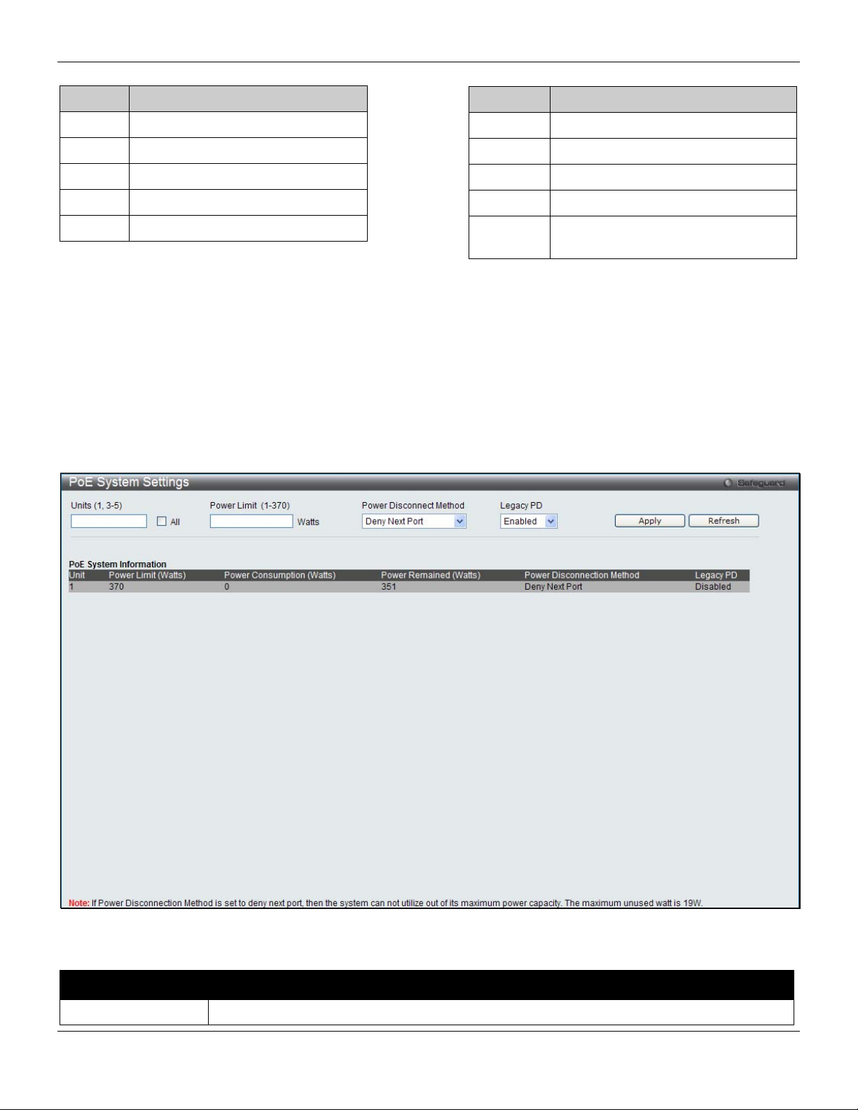
PoE System Settings
To view the following window, click System Configuration > PoE > PoE System Settings, as shown below:
Figure 2-7 PoE System Settings window
The following parameters can be configured:
Parameter Description
Unit (1, 3-5)
Select the unit to configure. Tick the All check box to select all units.
13
Page 23

xStack® DES-3528/DES-3552 Series Layer 2 Stackable Fast Ethernet Manage d Switch Web UI Reference Guide
Power Limit (1-370)
Power Disconnect
Method
Legacy PD
Click the Apply button to implement changes made.
Click the Refresh button to update the display section of this page.
Sets the limit of power to be used from the Switch’s power source to PoE ports. The user
may configure a Power Limit between 37W and 370W for the DES-3528P/DE S -3552P. The
default setting is 370W.
The PoE controller uses either Deny Next Port or Deny Low Priority Port to offset the power
limit being exceeded and keeps the Switch’s power at a usable level. Use the drop-down
menu to select a Power Disconnect Method. The default Power Disconnect Method is Deny
Next Port. Both Power Disconnection Methods are described below:
Deny Next Port - After the power limit has been exceeded, the next port attempting to power
up is denied, regardless of its priority. If Power Disconnection Method is set to Deny N ext
Port, the system cannot utilize out of its maximum power capacity. The maximum unused
watt is 19W.
Deny Low Priority Port - After the power limit has been exceeded, the next port attempting
to power up causes the port with the lowest priority to shut down so as to allow the highpriority and critical priority ports to power up.
Use the drop-down menu to enable or disable detecting legacy PDs signal.
PoE Port Settings
To view the following window, click System Configuration > PoE > PoE Port Settings, as shown below:
Figure 2-8 PoE Port Settings window
The following parameters can be configured:
Parameter Description
Unit
Select the unit to configure.
14
Page 24

xStack® DES-3528/DES-3552 Series Layer 2 Stackable Fast Ethernet Manage d Switch Web UI Reference Guide
From Port / To Port
State
Time Range
Priority
Power Limit
Click Apply to implement changes made. The port status of all PoE configured ports is displayed in the table in the
bottom half of the screen shown above.
Click the Refresh button to update the display section of this page.
Select a range of ports from the pull-down menus to be enabled or disabled for PoE.
Use the pull-down menu to enable or disable ports for PoE.
Select a range of the time to the port set as PoE. If Time Range is configured, the power
can only be supplied during the specified period of time.
Use the pull-down menu to select the priority of the PoE ports. Port priority determines the
priority which the system attempts to supply the power to the ports. There are three levels of
priority that can be selected, critical, high, and low. When multiple ports happen to have the
same level of priority, the port ID will be used to determine the priority. The lower port ID
has higher priority. The setting of priority will affect the order of supplying power. Whether
the disconnect method is set to deny low priority port, the priority of each port will be used
by the system to manage the supply of power to ports.
This function is used to configure the per-port power limit. If a port exceeds its power limit, it
will shut down.
Based on 802.3af/802.3at, there are different PD classes and power consumption range s;
Class 0 – 0.44~12.95W
Class 1 – 0.44~3.84W
Class 2 – 3.84~6.49W
Class 3 – 6.49~12.95W
Class 4 – 12.95W~29.5W (only ports 1~8)
The following is the power limit applied to the port for these five classes. For each class, the
power limit is a little more than the power consumption range for that class. This takes into
account any power loss on the cable. Thus, the following are the typical values;
Class 0 : 15400mW
Class 1 : 4000mW
Class 2 : 7000mW
Class 3 : 15400mW
User define: 30000mW (15400~30000 only applies to ports 1 - 8)
As well as these four pre-defined settings, users can directly specify any value ranging from
1000mW to 30000mW on DES-3528P/DES-3552P ports 1 to 8 and 1000mW - 15400mW
on DES-3528P ports 9 to 24/DES-3552P ports 9 to 48.
NOTE: DES-3528P/DES-3552P ports 1 to 8 can support PoE up to 30W by configuring the
PoE port user define value, also all ports can support 802.3af (1000 - 15400mW).
Serial Port Settings
This window allows the user to adjust the Baud Rate and the Auto Logout values.
To view the following window, click System Configuration > Serial Port Settings, as shown below:
Figure 2-9 Serial Port Settings window
15
Page 25
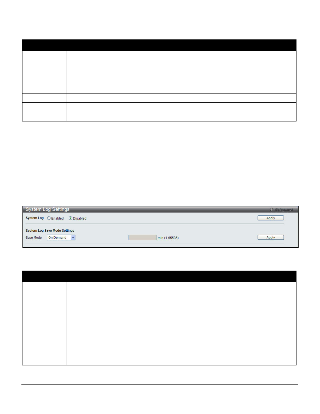
xStack® DES-3528/DES-3552 Series Layer 2 Stackable Fast Ethernet Manage d Switch Web UI Reference Guide
The fields that can be configured are described below:
Parameter Description
Baud Rate
Auto Logout
Data Bits
Parity Bits
Stop Bits
Click the Apply button to implement changes made.
Specify the baud rate for the serial port on the Switch. There are four possible baud rates to
choose from, 9600, 19200, 38400 and 115200. For a connection to the Switch using the console
port, the baud rate must be set to 115200, which is the default setting.
Select the logout time used for the console interface. This automatically logs the user out after
an idle period of time, as defined. Choose from the following options: 2, 5, 10, 15 minutes or
Never. The default setting is 10 minutes.
Display the data bits used for the serial port connection.
Display the parity bits used for the serial port connection.
Display the stop bits used for the serial port connection.
System Log configuration
System Log Settings
The Switch allows users to choose a method for which to save the switch log to the flash memory of the Switch.
To view the following window, click System Configuration > System Log Configuration > System Log Setting s, as
shown below:
Figure 2-10 System Log Settings window
The fields that can be configured are described below:
Parameter Description
System Log
Save Mode
Click the Apply button to accept the changes made for each individual section.
Use the radio buttons to enable or disable the system log settings. Click the Apply button to
accept the changes made.
Use the pull-down menu to choose the method for saving the switch log to the flash memory.
The user has three options:
On Demand – Users who choose this method will only save log files when they manually tell the
Switch to do so, either using the Save Log link in the Save folder or clicking the Save Log Now
button on this window.
Time Interval – Users who choose this method can configure a time interval by which the Switch
will save the log files, in the box adjacent to this configuration field. The user may set a time
between 1 and 65535 minutes.
Log Trigger – Users who choose this method will have log files saved to the Switch every time a
log event occurs on the Switch.
16
Page 26
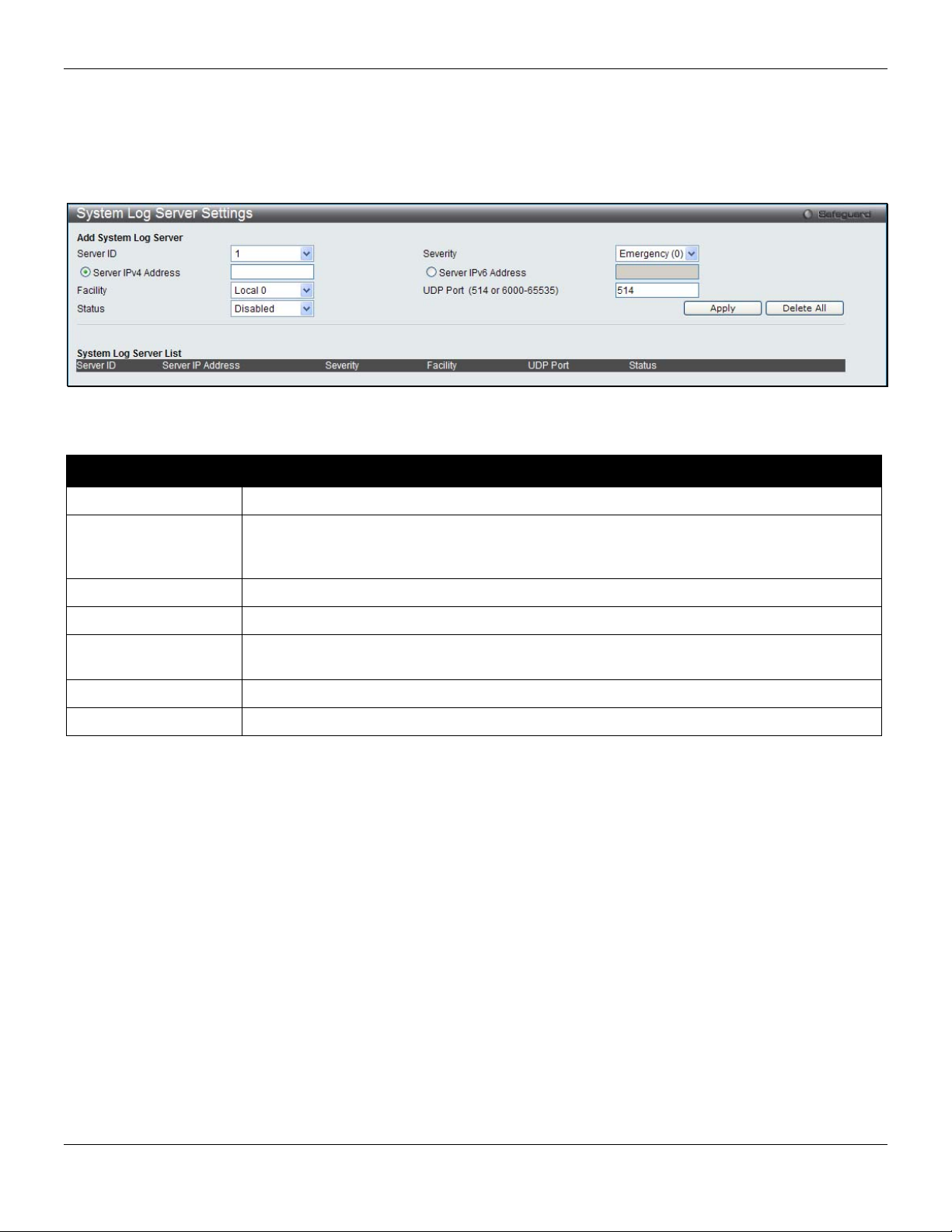
xStack® DES-3528/DES-3552 Series Layer 2 Stackable Fast Ethernet Manage d Switch Web UI Reference Guide
System Log Server Settings
The Switch can send System log messages to up to four designated servers using the System Log Server.
To view the following window, click System Configuration > System Log Configuration > System Log Server
Settings, as shown below:
Figure 2-11 System Log Server Settings
The fields that can be configured are described below:
Parameter Description
Server ID
Severity
Server IPv4 Address
Server IPv6 Address
Facility
UDP Port
Status
Click the Apply button to accept the changes made.
Click the Delete All button to remove all servers configured.
Syslog server settings index (1 to 4).
Use the drop-down menu to select the higher level of messages that will be sent. All
messages which level is higher than selecting level will be sent. The options are
Emergency, Alert, Critical, Error, Warning, Notice, Informational and Debug.
Click the radio button and enter the IPv4 address of the Syslog server.
Click the radio button and enter the IPv6 address of the Syslog server.
Use the drop-down menu to select Local 0, Local 1, Local 2, Local 3, Local 4, Local 5,
Local 6, or Local 7.
Type the UDP port number used for sending Syslog messages. The default is 514.
Choose Enabled or Disabled to activate or deactivate.
System Log
Users can view and delete the local history log as compiled by the Switch's management agent.
To view the following window, click System Configuration > System Log Configuration > System Log, as shown
below:
17
Page 27
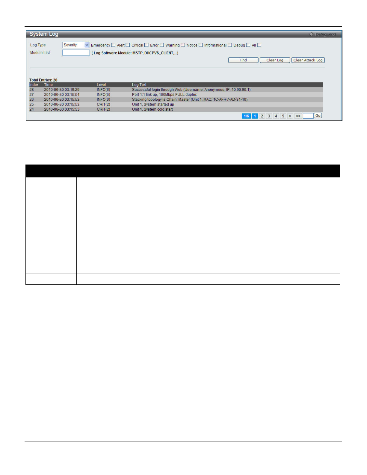
xStack® DES-3528/DES-3552 Series Layer 2 Stackable Fast Ethernet Manage d Switch Web UI Reference Guide
Figure 2-12 System Log window
The Switch can record event information in its own log. Click Go to go to the next page of the System Log window.
The fields that can be configured or viewed are described below:
Parameter Description
Log Type
Index
Time
Level
Log Text
Click the Find button to display the log in the display section according to the selection made.
Click the Clear Log button to clear the entries from the log in the display section.
Click the Clear Attack Log button to clear the entries from the attack log in the display section.
In the drop-down menu the user can select the log type that will be displayed.
Severity - When selecting Severity from the drop-down menu, a secondary tick must be made.
Secondary ticks are Emergency, Alert, Critical, Error, Warning, Notice, Informational and Debug.
To view all information in the log, simply tick the All check box.
Module List - When selecting Module List, the module name must be manu ally entered like
MSTP or ERPS.
Attack Log - When selecting Attack Log all attacks will be listed.
A counter incremented whenever an entry to the Switch's history log is made. The table displays
the last entry (highest sequence number) first.
Display the time in days, hours, minutes, and seconds since the Switch was last restarted.
Display the level of the log entry.
Display text describing the event that triggered the history log entry.
System Log & Trap Settings
The Switch allows users to configure the system log source IP interface addresses here.
To view the following window, click System Configuration > System Log Configuration > System Log & Trap
Settings, as shown below:
18
Page 28
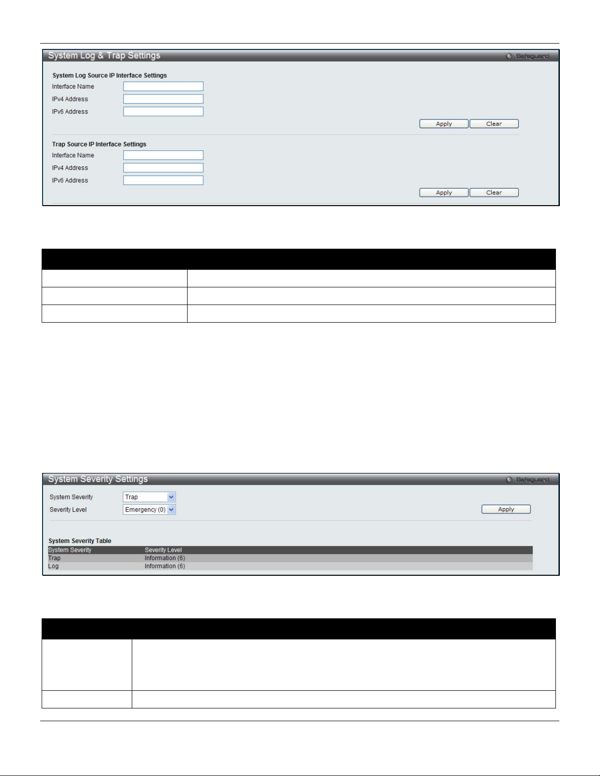
xStack® DES-3528/DES-3552 Series Layer 2 Stackable Fast Ethernet Manage d Switch Web UI Reference Guide
Figure 2-13 System Log & Trap Settings window (EI Mode Only)
The fields that can be configured are described below:
Parameter Description
Interface Name
IPv4 Address
IPv6 Address
Click the Apply button to accept the changes made for each individual section.
Click the Clear button to clear all the information entered in the fields.
Enter the IP interface name used.
Enter the IPv4 address used.
Enter the IPv6 address used.
System Severity Settings
The Switch can be configured to allow alerts be logged or sent as a trap to an SNMP agent or both. The level at which
the alert triggers either a log entry or a trap message can be set as well. Use the System Severity Settings window to
set the criteria for alerts. The current settings are displayed below the System Severity Table.
To view the following window, click System Configuration > System Log Configuration > System Severity
Settings, as shown below:
Figure 2-14 System Severity Settings window
The fields that can be configured are described below:
Parameter Description
System Severity
Severity Level
Choose how the alerts are used from the drop-down menu. Select Log to send the alert of the
Severity Type configured to the Switch’s log for analysis. Choose Trap to send it to an SNMP
agent for analysis, or select All to send the chosen alert type to an SNMP agent and the
Switch’s log for analysis.
This drop-down menu allows you to select the level of messages that will be sent. The options
19
Page 29
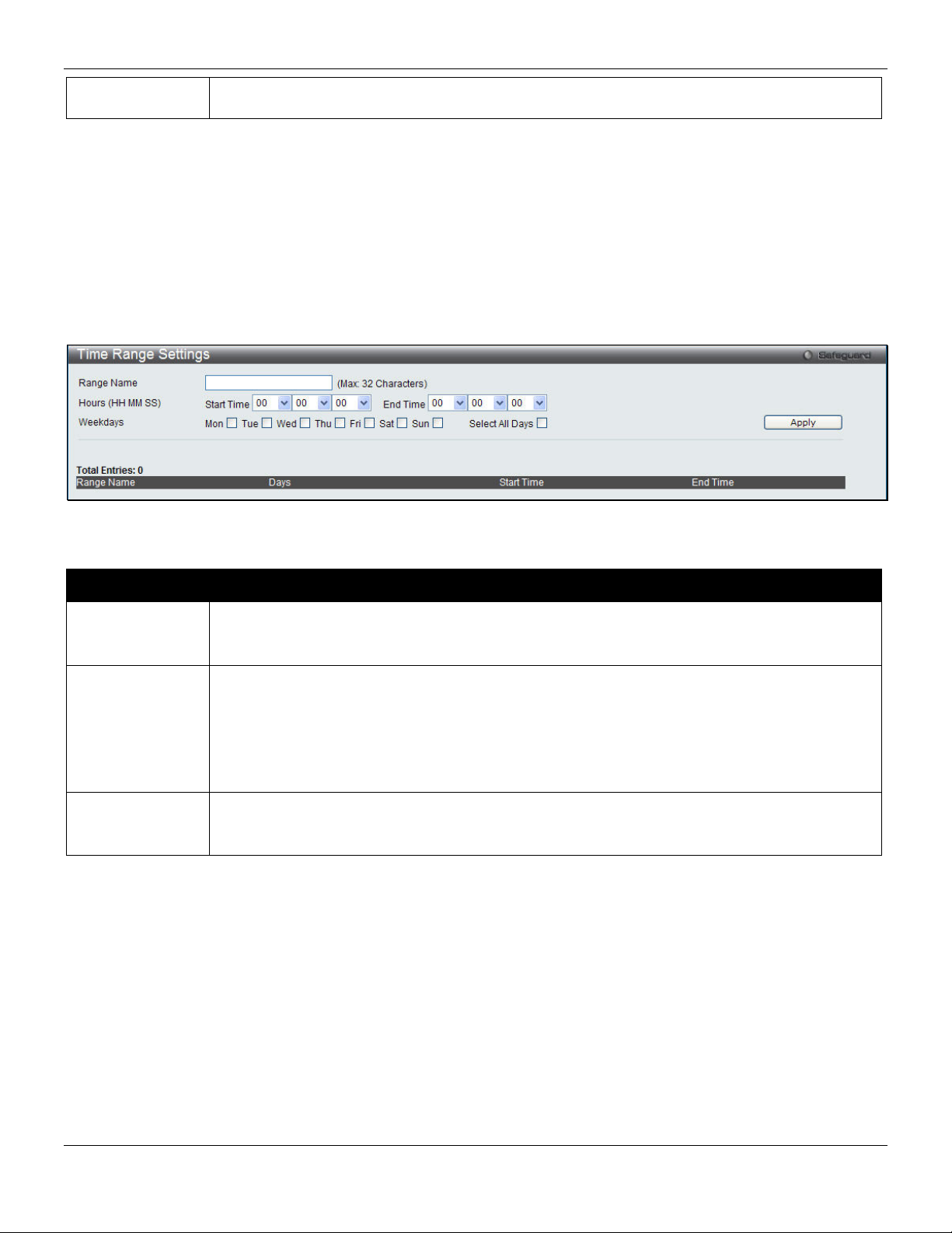
xStack® DES-3528/DES-3552 Series Layer 2 Stackable Fast Ethernet Manage d Switch Web UI Reference Guide
are Emergency (0), Alert (1), Critical (2), Error (3), Warning (4), Notice (5), Information(6) and
Debug(7).
Click the Apply button to accept the changes made.
Time Range Settings
Time range is a time period that the respective function will take an effect on, such as ACL. For example, the
administrator can configure the time based ACL to allow users to surf the Internet on every Saturday and every Sunday,
meanwhile to deny users to surf the Internet on weekdays.
The user may enter up to 64 time range entries on the Switch.
To view the following window, click System Configuration > Time Range Settings, as shown below:
Figure 2-15 Time Range Settings window
The fields that can be configured are described below:
Parameter Description
Range Name
Hours
Weekdays
Click the Apply button to accept the changes made. Current configured entries will be displayed in the table in the
bottom half of the window shown above.
Enter a name of no more than 32 alphanumeric characters that will be used to identify this time
range on the Switch. This range name will be used in the Access Profile table to identify the
access profile and associated rule to be enabled during this time range.
This parameter is used to set the time in the day that this time range is to be enabled using the
following parameters:
Start Time - Use this parameter to identify the starting time of the time range, in hours, minutes
and seconds, based on the 24-hour time system.
End Time - Use this parameter to identify the ending time of the time range, in hours, minutes
and seconds, based on the 24-hour time system.
Use the check boxes to select the corresponding days of the week that this time range is to be
enabled. Tick the Select All Days check box to configure this time range for every day of the
week.
Time Settings
Users can configure the time settings for the Switch.
To view the following window, click System Configuration > Time Settings, as shown below:
20
Page 30

xStack® DES-3528/DES-3552 Series Layer 2 Stackable Fast Ethernet Manage d Switch Web UI Reference Guide
Figure 2-16 Time Settings window
The fields that can be configured are described below:
Parameter Description
Date (DD/MM/YYYY)
Time (HH:MM:SS)
Click the Apply button to accept the changes made.
Enter the current day, month, and year to update the system clock.
Enter the current time in hours, minutes, and seconds.
User Accounts Settings
The Switch allows the control of user privileges.
To view the following window, click System Configuration > User Accounts Settings, as shown below:
Figure 2-17 User Accounts Settings window
To add a new user, type in a User Name and New Password and retype the same password in the Confirm New
Password field. Choose the level of privilege (Admin, Operator, Power_User or User) from the Access Right drop-down
menu.
Management Admin Operator Power_User User
Configuration Read/Write Read/Write–
partly
Network Monitoring Read/Write Read/Write Read-only Read-only
Community Strings and Trap
Stations
Update Firmware and Configuration
Files
System Utilities Read/Write Read-only Read-only Read-only
Factory Reset Read/Write No No No
User Account Management
Add/Update/Delete User Accounts Read/Write No No No
View User Accounts Read/Write No No No
Read/Write Read-only Read-only Read-only
Read/Write No No No
Read/Write–
partly
No
21
Page 31

xStack® DES-3528/DES-3552 Series Layer 2 Stackable Fast Ethernet Manage d Switch Web UI Reference Guide
The fields that can be configured are described below:
Parameter Description
User Name
Password
Confirm Password
Access Right
Click the Apply button to accept the changes made.
NOTICE: In case of lost passwords or password corruption, please refer to the appendix chapter entitled,
“Password Recovery Procedure,” which will guide you through the steps necessary to resolve this issue.
NOTE: The username and password should be less than 16 characters.
Enter a new user name for the Switch.
Enter a new password for the Switch.
Re-type in a new password for the Switch.
Specify the access right for this user.
Stacking
From firmware release v2.00 of this Switch, the DES-3528/DES-3552 Series now supports switch stacking, where a set
of eight switches can be combined to be managed by one IP address through Telnet, the GUI interface (Web), the
console port or through SNMP. Each switch of this series has two stacking ports located at the rear of the device,
which can be used to connect stacking enabled devices and make them stack together. After adding these stackin g
ports, the user may connect these ports together using copper cables (also sold separately) in one of two possible
topologies.
Duplex Chain – As shown in Figure 2-18, The Duplex Chain topology stacks switches together in a chain-link format.
Using this method, data transfer is only possible in one direction and if there is a break in the chain, then data transfer
will obviously be affected.
Duplex Ring – As shown in Figure 2-19, the Duplex Ring stacks switches in a ring or circle format where data can be
transferred in two directions. This topology is very resilient due to the fact that if there is a break in the ring, data can
still be transferred through the stacking cables between switches in the stack.
22
Page 32

xStack® DES-3528/DES-3552 Series Layer 2 Stackable Fast Ethernet Manage d Switch Web UI Reference Guide
Figure 2-18 Switches stacked in a Duplex Chain Figure 2-19 Switches stacked in a Duplex Ring
Within each of these topologies, each switch plays a role in the Switch stack. These roles can be set by the user per
individual Switch, or if desired, can be automatically determined by the Switch stack. Three possible roles exist when
stacking with the DES-3528/DES-3552 Series.
NOTE: Only ports 27 and 28 of the DES-3528/DES-3552 Series, or ports 51 and ports 52 of DES-
3552/DES-3552P support stacking. The other ports cannot be used for stacking. For a stacki ng
disabled device, ports 27 and 28 of the DES-3528 Series, or ports 51 and ports 52 of DES3552/DES-3552P can be used as normal GE ports.
Primary Master – The Primary Master is the leader of the stack. It will maintain normal operations, monitor operations
and the running topology of the Stack. This switch will also assign Stack Unit IDs, synchronize configurations and
transmit commands to remaining switches in the switch stack. The Primary Master can be manually set by assigning
this Switch the highest priority (a lower number denotes a higher priority) before physically assembling the stack, or it
can be determined automatically by the stack through an election process which determines the lowest MAC address
and then will assign that switch as the Primary Master, if all priorities are the same. The Primary master are physically
displayed by the seven segment LED to the far right on the front panel of the switch where this LED will flash between
its given Box ID and ‘H’.
Backup Master – The Backup Master is the backup to the Primary Master, and will take over the functions of the
Primary Master if the Primary Master fails or is removed from the Stack. It also monitors the status of neighbori ng
switches in the stack, will perform commands assigned to it by the Primary Master and will monitor the running status
of the Primary Master. The Backup Master can be set by the user by assigning this Switch the second highest priority
before physically assembling the stack, or it can be determined automatically by the stack through an election proces s
which determines the second lowest MAC address an d then will a s sign that switch as the Backup Master, if all
priorities are the same.
Slave – Slave switches constitute the rest of the switch stack and although not Primary or Backup Masters, they can
be placed into these roles when these other two roles fail or are removed from the stack. Slave switches p erform
operations requested by the master, monitor the status of neighbor switches in the stack and the stack topology and
adhere to the Backup Master’s commands once it becomes a Primary Master. Slave switches will do a self-check to
determine if it is to become the Backup Master if the Backup Master is promoted to the Primary Master, or if the
Backup Master fails or is removed from the switch stack. If both Primary and Backup masters fail, or are removed from
the Switch stack, it will determine if it is to become the Primary Master. These roles will be determined, first by priority
and if the priority is the same, the lowest MAC address.
Once switches have been assembled in the topology desired by the user and powered on, the stack will undergo three
processes until it reaches a functioning state.
23
Page 33

xStack® DES-3528/DES-3552 Series Layer 2 Stackable Fast Ethernet Manage d Switch Web UI Reference Guide
Initialization State – This is the first state of the stack, where the runtime codes are set and initialized and the system
conducts a peripheral diagnosis to determine each individual switch is functioning properly.
Master Election State – Once the codes are loaded and initialized, the stack will undergo the Master Election State
where it will discover the type of topology used, elect a Primary Master and then a Backup Master.
Synchronization State – Once the Primary Master and the Backup Master have been established, the Primary Master
will assign Stacking Unit IDs to switches in the stack, synchronize configurations for all switches and then transmit
commands to the rest of the switches based on the users configurations of the Primary Master.
Once these steps have been completed, the switch stack will enter a normal operating mode.
Stack Switch Swapping
The stacking feature of the Switch supports “hot swapping” of switches in and out of the running stack. Use rs may
remove or add switches to the stack without powering down or largely affecting the transfer of data between switches
in the stack, with a few minor provisions.
When switches are “hot inserted” into the running stack, the new switch may take on the Primary Master, Backup
Master or Slave role, depending on configurations set on the newly added switch, such as configured priority or MAC
address. Yet, if adding two stacks together that have both previously undergone the election process, and therefore
both have a Primary Master and a Backup master, a new Primary Master will be elected from one of the already
existing Primary Masters, based on priority or MAC address. This Primary Master will take over all of the Primary
Master’s roles for all new switches that were hot inserted. This process is done using discovery packet s that circulate
through the switch stack every 1.5 seconds until the discovery process has been compl eted.
The “hot remove” action means removing a device from the stack while the stack is still running. The hot removal is
detected by the stack when it fails to receive heartbeat packets during its specified interval from a device, or when one
of the stacking ports links is down. Once the device has been removed, the remaining switches will update their
stacking topology database to reflect the change. Any one of the three roles, Primary Master, Backup Master or Slave,
may be removed from the stack, yet different processes occur for each specific device removal.
If a Slave device has been removed, the Primary Master will inform other switches of the hot remove of this device
through the use of unit leave messages. Switches in the stack will clear the configurations of the unit removed, and
dynamically learned databases, such as ARP, will be cleared as well.
If the Backup Master has been hot removed, a new Backup Master will be chosen through the election pro c ess
previously described. Switches in the stack will clear the configurations of the unit removed, and dynamically learned
databases, such as ARP, will be cleared as well. Then the Backup Master will begin backing up the Primary Master
when the database synchronization has been completed by the stack.
If the Primary Master is removed, the Backup Master will assume the Primary Master’s role and a new Backup Master
will be chosen using the election process. Switches in the stack will clear the configurations of the unit remo ved, and
dynamically learned databases, such as ARP, will be cleared as well. The new Primary Master will inherit the MAC and
IP address of the previous Primary Master to avoid conflict within the stack and the network itself.
If both the Primary Master and the Backup Master are removed, the election process is immediately processed and a
new Primary Master and Backup Master is determined. Switches in the stack will clear the configurations of the units
removed, and dynamically learned databases, such as ARP, will be cleared as well. Static switch configurations still
remain in the database of the remaining switches in the stack and those functions will not be affected.
NOTE: If there is a Box ID conflict when the stack is in the discovery phase, the device will enter
a special standalone topology mode. Users can only get device information, configure
Box IDs, save and reboot. All stacking ports will be disabled and an error me ssage will be
produced on the local console port of each device in the stack. Users must reconfigure
Box IDs and reboot the stack.
Stacking Device Table
This window is used to display the current devices in the Switch Stack.
To view this window, click System Configuration > Stacking > Stacking Device Table, as shown below:
24
Page 34

xStack® DES-3528/DES-3552 Series Layer 2 Stackable Fast Ethernet Manage d Switch Web UI Reference Guide
Figure 2-20 Stacking Device Table window
Stacking Mode Settings
To begin the stacking process, users must first enable this device for stacking by using the Stacking Mode Settings
window.
To view this window, click System Configuration > Stacking > Stacking Mode Settings, as shown below:
Figure 2-21 Stacking Mode Settings window
The fields that can be configured or viewed are described below:
Parameter Description
Stacking Mode
Force Master Role
Current Box ID
New Box ID
Priority (1-63)
Click the Apply button to accept the changes made.
Click the radio buttons to enable or disable the stacking function.
Use the radio buttons to enable or disable the function. It is used to ensure the master role is
unchanged when adding a new device to the current stacking topology. If the Enabled radio
button is selected, the master’s priority will become zero after the stacking has stabilized.
The Box ID of the Switch in the stack to be configured.
The new box ID of the selected switch in the stack that was selected in the Current Box ID
field. The user may choose any number between 1 and 8 to identify the Switch in the switch
stack. Auto will automatically assign a box number to the Switch in the switch stack.
Displays the priority ID of the Switch. The lower the number, the higher the priority. The box
(switch) with the lowest priority number in the stack is the Primary Master switch. The Primary
Master switch will be used to configure applications of the switch stack.
25
Page 35

xStack® DES-3528/DES-3552 Series Layer 2 Stackable Fast Ethernet Manage d Switch Web UI Reference Guide
Chapter 3 Management
ARP
Gratuitous ARP
IPv6 Neighbor Settings
IP Interface
Management Settings
Session Table
Single IP Management
SNMP Settings
Telnet Settings
Web Settings
ARP
Static ARP Settings
The Address Resolution Protocol is a TCP/IP protocol that converts IP addresses into physical addresses. This table
allows network managers to view, define, modify, and delete ARP information for specific devices. Static entries can be
defined in the ARP table. When static entries are defined, a permanent entry is entered and is used to translate IP
addresses to MAC addresses.
To view the following window, click Management > ARP > Static ARP Settings, as shown below:
Figure 3-1 Static ARP Settings window
The fields that can be configured are described below:
Parameter Description
ARP Aging Time (0-65535)
IP Address
MAC Address
Click the Apply button to accept the changes made for each individual section.
Click the Delete All button to remove all the entries listed.
Click the Edit button to re-configure the specific entry.
The ARP entry age-out time, in minutes. The default is 20 minutes.
The IP address of the ARP entry.
The MAC address of the ARP entry.
26
Page 36

xStack® DES-3528/DES-3552 Series Layer 2 Stackable Fast Ethernet Manage d Switch Web UI Reference Guide
Click the Delete button to remove the specific entry.
Proxy ARP Settings
The Proxy ARP (Address Resolution Protocol) feature of the Switch will allow the Switch to reply to ARP requests
destined for another device by faking its identity (IP and MAC Address) as the original ARP responder. Therefore, the
Switch can then route packets to the intended destination without configuring static routing or a default gateway.
The host, usually a layer 3 switch, will respond to packets destined for another device. For example, if hosts A and B
are on different physical networks, B will not receive ARP broadcast requests from A and therefore cannot respond.
Yet, if the physical network of A is connected by a router or layer 3 switch to B, the router or Layer 3 switch will see the
ARP request from A.
This local proxy ARP function allows the Switch to respond to the proxy ARP, if the source IP and destination IP are in
the same interface.
To view the following window, click Management > ARP > Proxy ARP Settings, as shown below:
Figure 3-2 Proxy ARP Settings window
Click the Edit button to re-configure the specific entry and select the proxy ARP state of the IP interface. By default,
both the Proxy ARP State and Local Proxy ARP State are disabled.
ARP Table
Users can display current ARP entries on the Switch.
To view the following window, click Management > ARP > ARP Table, as shown below:
Figure 3-3 ARP Table window
The fields that can be configured are described below:
Parameter Description
Interface Name
IP Address
Enter or view the Interface name used.
Enter or view the IP Address used.
MAC Address
Click the Find button to locate a specific entry based on the information entered.
Click the Show Static button to display only the static entries in the display table.
Enter or view the MAC Address used.
27
Page 37

xStack® DES-3528/DES-3552 Series Layer 2 Stackable Fast Ethernet Manage d Switch Web UI Reference Guide
Click the Clear All button to remove all the entries listed in the table.
Enter a page number and click the Go button to navigate to a specific page when multiple pages exist.
Gratuitous ARP
Gratuitous ARP Global Settings
An ARP announcement (also known as Gratuitous ARP) is a packet (usually an ARP Request) containing a valid SHA
and SPA for the host which sent it, with TPA equal to SPA. Such a request is not intended to solicit a reply, but merely
updates the ARP caches of other hosts which receive the packet.
This is commonly done by many operating systems on startup, and helps to resolve problems which would otherwise
occur if, for example, a network card had recently been changed (changing the IP address to MAC address mapping)
and other hosts still had the old mapping in their ARP cache.
The user can enable or disable the gratuitous ARP global settings here. To view the following window, click
Management > Gratuitous ARP > Gratuitous ARP Global Settings, as shown below:
Figure 3-4 Gratuitous ARP Global Settings Window
The fields that can be configured are described below:
Parameter Description
Send On IP Interface
Status Up
Send On Duplicate IP
Detected
Gratuitous ARP
Learning
Click the Apply button to accept the changes made.
The command is used to enable/disable sending of gratuitous ARP request packet while
the IPIF interface become up. This is used to automatically announce the interface’s IP
address to other nodes. By default, the state is disabled, and only one gratuitous ARP
packet will be broadcast.
The command is used to enable/disable the sending of gratuitous ARP request packet
while a duplicate IP is detected. By default, the state is disabled. For this command, the
duplicate IP detected means that the system received an ARP request packet that is
sent by an IP address that match the system’s own IP address. In this case, the system
knows that somebody out there uses an IP address that is conflict with the system. In
order to reclaim the correct host of this IP address, the system can send out the
gratuitous ARP request packets for this duplicate IP address.
Normally, the system will only learn the ARP reply packet or a normal ARP request
packet that asks for the MAC address that corresponds to the system’s IP address. The
command is used to enable/disable learning of ARP entry in ARP cache based on the
received gratuitous ARP packet. The gratuitous ARP packet is sent by a source IP
address that is identical to the IP that the packet is queries for. By default, the state is
Disabled status.
NOTE: With the gratuitous ARP learning, the system will not learn new entry but only do the update on
the ARP table based on the received gratuitous ARP packet.
28
Page 38

xStack® DES-3528/DES-3552 Series Layer 2 Stackable Fast Ethernet Manage d Switch Web UI Reference Guide
Gratuitous ARP Settings
The user can configure the IP interface’s gratuitous ARP parameter.
To view the following window, click Management > Gratuitous ARP > Gratuitous ARP Settings, as shown below:
Figure 3-5 Gratuitous ARP Settings window
The fields that can be configured are described below:
Parameter Description
Trap
Log
Interface Name
Interval Time
Click the Apply button to accept the changes made for each individual section.
Use the drop-down menu to enable or disable the trap option. By default the trap is
Disabled.
Use the drop-down menu to enable or disable the logging option. By default the event
log is Enabled.
Enter the interface name of the Layer 3 interface. Select All to enable or disable
gratuitous ARP trap or log on all interfaces.
Enter the periodically send gratuitous ARP interval time in seconds. 0 means that
gratuitous ARP request will not be sent periodically. By default the interval time is 0.
IPv6 Neighbor Settings
The user can configure the Switch’s IPv6 neighbor settings. The Switch’s current IPv6 neighbor settings will be
displayed in the table at the bottom of this window.
To view the following window, click Management > IPv6 Neighbor Settings, as shown below:
Figure 3-6 IPv6 Neighbor Settings window
The fields that can be configured are described below:
29
Page 39

xStack® DES-3528/DES-3552 Series Layer 2 Stackable Fast Ethernet Manage d Switch Web UI Reference Guide
Parameter Description
Interface Name
Neighbor IPv6 Address
Link Layer MAC Address
Interface Name
State
Click the Add button to add a new entry based on the information entered.
Click the Find button to locate a specific entry based on the information entered.
Click the Clear button to clear all the information entered in the fields.
Enter the interface name of the IPv6 neighbor.
Enter the neighbor IPv6 address.
Enter the link layer MAC address.
Enter the interface name of the IPv6 neighbor. To search for all the current interfaces
on the Switch, go to the second Interface Name field in the middle part of the window,
tick the All check box. Tick the Hardware option to display all the neighbor cache
entries which were written into the hardware table.
Use the drop-down menu to select All, Address, Static, or Dynamic. When the user
selects address from the drop-down menu, the user will be able to enter an IP address
in the space provided next to the state option.
IP Interface
System IP Address Settings
The IP address may initially be set using the console interface prior to connecting to it through the Ethernet. The Web
manager will display the Switch’s current IP settings.
NOTE: The Switch’s factory default IP address is 10.90.90.90 with a subnet mask of 255.0.0.0 and a
To view the following window, click Management > IP Interface > System IP Address Settings, as shown below:
The fields that can be configured are described below:
Parameter Description
Static
default gateway of 0.0.0.0.
Figure 3-7 System IP Address Settings window
Allow to assign the entry of an IP address, subnet mask, and a default gateway for the
Switch manually.
DHCP
The Switch will send out a DHCP broadcast request when it is powered up. The DHCP
30
Page 40

xStack® DES-3528/DES-3552 Series Layer 2 Stackable Fast Ethernet Manage d Switch Web UI Reference Guide
protocol allows IP addresses, network masks, and default gateways to be assigned by a
DHCP server. If this option is set, the Switch will first look for a DHCP server to provide it
with this information before using the default or previously entered settings.
BOOTP
Interface Name
Management VLAN
Name
Interface Admin
State
IP Address
Subnet Mask
The Switch will send out a BOOTP broadcast request when it is powered up. The BOOTP
protocol allows IP addresses, network masks, and default gateways to be assigned by a
central BOOTP server. If this option is set, the Switch will first look for a BOOTP server to
provide it with this information before using the default or previously entered settings.
Display the System interface name.
This allows the entry of a VLAN name from which a management station will be allowed to
manage the Switch using TCP/IP (in-band via Web manager or Telnet). Management
stations that are on VLANs other than the one entered here will not be able to manage the
Switch in-band unless their IP addresses are entered in the Trusted Host Settings window
(Security > Trusted Host Settings). If VLANs have not yet been configured for the Switch,
the default VLAN contains all of the Switch’s ports. There are no entries in the Trusted Host
table, by default, so any management station that can connect to the Switch can access the
Switch until a management VLAN is specified or Management Station IP addresses are
assigned.
Use the drop-down menu to enable or disable the configuration on this interface.
This field allows the entry of an IPv4 address to be assigned to this IP interface. These
fields should be of the form xxx.xxx.xxx.xxx, where each xxx is a number (represented in
decimal form) between 0 and 255. This address should be a unique address on the network
assigned for use by the network administrator.
A Bitmask that determines the extent of the subnet that the Switch is on. Should be of the
form xxx.xxx.xxx.xxx, where each xxx is a number (represented in decimal) between 0 and
255. The value should be 255.0.0.0 for a Class A network, 255.255.0.0 for a Class B
network, and 255.255.255.0 for a Class C network, but custom subnet masks are allowed.
Gateway
Click the Apply button to accept the changes made.
IP address that determines where packets with a destination address outside the current
subnet should be sent. This is usually the address of a router or a host acting as an IP
gateway. If your network is not part of an intranet, or you do not want the Switch to be
accessible outside your local network, you can leave this field unchanged.
Interface Settings
Users can display the Switch’s current IP interface settings.
To view the following window, click Management > IP Interface > Interface Settings, as shown below:
Figure 3-8 Interface Settings window
The fields that can be configured are described below:
Parameter Description
31
Page 41

xStack® DES-3528/DES-3552 Series Layer 2 Stackable Fast Ethernet Manage d Switch Web UI Reference Guide
Interface Name
Enter the name of the IP interface to search for.
Click the Find button to locate a specific entry based on the information entered.
Click the Add button to add a new entry based on the information entered.
Click the Delete All button to remove all the entries listed.
Click the IPv4 Edit button to edit the IPv4 settings for the specific entry.
Click the IPv6 Edit button to edit the IPv6 settings for the specific entry.
Click the Delete button to remove the specific entry.
NOTE: To create IPv6 interfaces, the user has to create an IPv4 interface then edit it to IPv6.
Click the Add button to see the following window.
Figure 3-9 IPv4 Interface Settings – Add window
The fields that can be configured are described below:
Parameter Description
IP Interface Name
IPv4 Address
Subnet Mask
VLAN Name
Interface Admin State
Enter the name of the IP interface being created.
Enter the IPv4 address used.
Enter the IPv4 subnet mask used.
Enter the VLAN Name used.
Use the drop-down menu to enable or disable the Interface Admin State.
Click the Apply button to accept the changes made.
Click the <<Back button to discard the changes made and return to the previous page.
Click the IPv4 Edit button to see the following window.
Figure 3-10 IPv4 Interface Settings – IPv4 Edit window
32
Page 42

xStack® DES-3528/DES-3552 Series Layer 2 Stackable Fast Ethernet Manage d Switch Web UI Reference Guide
The fields that can be configured are described below:
Parameter Description
Get IP From
Use the drop-down menu to specify the method that this Interface uses to acquire an IP
address.
Interface Name
IPv4 Address
Subnet Mask
VLAN Name
IPv4 State
Interface Admin State
Enter the name of the IP interface being configured.
Enter the IPv4 address used.
Enter the IPv4 subnet mask used.
Enter the VLAN Name used.
Use the drop-down menu to enable or disable IPv4 State.
Use the drop-down menu to enable or disable the Interface Admin State.
Click the Apply button to accept the changes made.
Click the <<Back button to discard the changes made and return to the previous page.
Click the IPv6 Edit button to see the following window.
Figure 3-11 IPv6 Interface Settings – IPv6 Edit window
The fields that can be configured are described below:
Parameter Description
Interface Name
IPv6 State
Interface Admin State
IPv6 Network Address
Display the IPv6 interface name.
Use the drop-down menu to enable or disable IPv6 State.
Use the drop-down menu to enable or disable the Interface Admin State.
Enter the neighbor’s global or local link address.
(e.g.: 3710::1/64)
DHCPv6 Client
NS Retransmit Time (0-
4394967295)
Use the drop-down menu to enable or disable the DHCPv6 client.
Enter the Neighbor solicitation’s retransmit timer in millisecond here. It has the same
value as the RA retransmit time in the configuration of the IPv6 ND RA command. If
this field is configure, it will duplicate the enter into the RA field.
Automatic Link Local
Use the drop-down menu to enable or disable the Automatic Link Local Address.
Address
Click the Apply button to accept the changes made for each individual section.
Click the <<Back button to discard the changes made and return to the previous page.
Click the View All IPv6 Address
link to view all the current IPv6 address.
33
Page 43

xStack® DES-3528/DES-3552 Series Layer 2 Stackable Fast Ethernet Manage d Switch Web UI Reference Guide
Click the View All IPv6 Address
Figure 3-12 IPv6 Interface Settings – View All IPv6 Address window
Click the <<Back button to return to the previous page.
link to see the following window.
Management Settings
Users can stop the scrolling of multiple pages beyond the limits of the console when using the Command Line Interface.
This window is also used to enable the DHCP auto configuration feature on the Switch. When enabled, the Switch is
instructed to receive a configuration file from a TFTP server, which will set the Switch to become a DHCP client
automatically on boot-up. To employ this method, the DHCP server must be set up to deliver the TFTP server IP
address and configuration file name information in the DHCP reply packet. The TFTP server must be up and running
and hold the necessary configuration file stored in its base directory when the request is received from the Switch. For
more information about loading a configuration file for use by a client, see the DHCP server and/or TFTP server
software instructions. The user may also consult the Upload Log File window description located in the Tools section
of this manual.
If the Switch is unable to complete the DHCP auto configuration, the previously saved configuration file present in the
Switch’s memory will be used.
This window also allows the user to implement the Switch’s built-in power saving feature. When power saving is
Enabled, a port which has a link down status will be turned off to save power to the Switch. This will not affect the
port’s capabilities when the port status is link up.
Users can also configure Password Encryption on the Switch.
To view the following window, click Management > Management Settings, as shown below:
Figure 3-13 Management Settings window
The fields that can be configured are described below:
Parameter Description
CLI Paging State
Command Line Interface paging stops each page at the end of the console. This allows
you to stop the scrolling of multiple pages of text beyond the limits of the console. CLI
Paging is Enabled by default. To disable it, click the Disabled radio button.
34
Page 44

xStack® DES-3528/DES-3552 Series Layer 2 Stackable Fast Ethernet Manage d Switch Web UI Reference Guide
DHCP Auto
Configuration State
Password Encryption
State
Click the Apply button to accept the changes made.
Enable or disable the Switch’s DHCP auto configuration feature. When enabled, the
Switch is instructed to receive a configuration file from a TFTP server, which will set the
Switch to become a DHCP client automatically on boot-up. To employ this method, the
DHCP server must be set up to deliver the TFTP server IP address and configuration file
name information in the DHCP reply packet. The TFTP server must be up and running
and hold the necessary configuration file stored in its base directory when the request is
received from the Switch. The default is Disabled.
Password encryption will encrypt the password configuration in configuration files.
Password encryption is Disabled by default. To enable password encryption, click the
Enabled radio button.
Session Table
Users can display the management sessions since the Switch was last rebooted.
To view the following window, click Management > Session Table, as shown below:
Figure 3-14 Session Table window
Click the Refresh button to refresh the display table so that new entries will appear.
Single IP Management
Simply put, D-Link Single IP Management is a concept that will stack switches together over Ethernet instead of using
stacking ports or modules. There are some advantages in implementing the “Single IP Management” feature:
1. SIM can simplify management of small workgroups or wiring closets while scaling the network to handle
increased bandwidth demand.
2. SIM can reduce the number of IP address needed in your network.
3. SIM can eliminate any specialized cables for stacking connectivity and remove the distance barriers that
typically limit your topology options when using other stacking technology.
Switches using D-Link Single IP Management (labeled here as SIM) must conform to the following rules:
• SIM is an optional feature on the Switch and can easily be enabled or disabled through the Command Line
Interface or Web Interface. SIM grouping has no effect on the normal operation of the Switch in the user’s
network.
• There are three classifications for switches using SIM. The Commander Switch (CS), which is the master
switch of the group, Member Switch (MS), which is a switch that is recognized by the CS a member of a SIM
group, and a Candidate Switch (CaS), which is a Switch that has a physical link to the SIM group but has not
been recognized by the CS as a member of the SIM group.
• A SIM group can only have one Commander Switch (CS).
• All switches in a particular SIM group must be in the same IP subnet (broadcast domain). Members of a SIM
group cannot cross a router.
• A SIM group accepts up to 32 switches (numbered 1-32), not including the Commander Switch (num bered 0).
35
Page 45

xStack® DES-3528/DES-3552 Series Layer 2 Stackable Fast Ethernet Manage d Switch Web UI Reference Guide
• There is no limit to the number of SIM groups in the same IP subnet (broadcast domain); however a single
switch can only belong to one group.
• If multiple VLANs are configured, the SIM group will only utilize the default VLAN on any switch.
• SIM allows intermediate devices that do not support SIM. This enables the user to manage switches that are
more than one hop away from the CS.
The SIM group is a group of switches that are managed as a single entity. The Switch may take on three different roles:
1. Commander Switch (CS) – This is a switch that has been manually configured as the controlling device for a
group, and takes on the following characteristics:
a. It has an IP Address.
b. It is not a command switch or member switch of another Single IP group.
c. It is connected to the member switches through its management VLAN.
2. Member Switch (MS) – This is a switch that has joined a single IP group and is acce ssible from the CS, and it
takes on the following characteristics:
a. It is not a CS or MS of another IP group.
b. It is connected to the CS through the CS management VLAN.
3. Candidate Switch (CaS) – This is a switch that is ready to join a SIM group but is not yet a member of the SIM
group. The Candidate Switch may join the SIM group of the Switch by manually configuring it to be a MS of a
SIM group. A switch configured as a CaS is not a member of a SIM group and will take on the following
characteristics:
a. It is not a CS or MS of another Single IP group.
b. It is connected to the CS through the CS management VLAN
The following rules also apply to the above roles:
• Each device begins in a Candidate state.
• CSs must change their role to CaS and then to MS, to become a MS of a SIM group. Thus, the CS cannot
directly be converted to a MS.
• The user can manually configure a CS to become a CaS.
• A MS can become a CaS by:
• Being configured as a CaS through the CS.
• If report packets from the CS to the MS time out.
• The user can manually configure a CaS to become a CS
• The CaS can be configured through the CS to become a MS.
After configuring one switch to operate as the CS of a SIM group, additionalDES-3528/DES-3552 Series switches may
join the group by manually configuring the Switch to be a MS. The CS will then serve as the in band entry point for
access to the MS. The CS’s IP address will become the path to all MS’s of the group and the CS’s Administrator’s
password, and/or authentication will control access to all MS’s of the SIM group.
With SIM enabled, the applications in the CS will redirect the packet instead of executing the packets. The applications
will decode the packet from the administrator, modify some data, and then send it to the MS. After execution, the CS
may receive a response packet from the MS, which it will encode and send it back to the administrator.
When a CaS becomes a MS, it automatically becomes a member of the first SNMP community (includes read/write
and read only) to which the CS belongs. However, if a MS has its own IP address, it can belong to SNMP communities
to which other switches in the group, including the CS, do not belong.
36
Page 46

xStack® DES-3528/DES-3552 Series Layer 2 Stackable Fast Ethernet Manage d Switch Web UI Reference Guide
Upgrade to v1.61
To better improve SIM management, the DES-3528/DES-3552 Series switches have been up graded to version 1.61 in
this release. Many improvements have been made, including:
1. The Commander Switch (CS) now has the capability to automatically rediscover member switches that have
left the SIM group, either through a reboot or web malfunction. This feature is accomplished through the use of
Discover packets and Maintenance packets that previously set SIM members will emit after a reboot. Once a
MS has had its MAC address and password saved to the CS’s database, if a reboot occurs in the MS, the CS
will keep this MS information in its database and when a MS has been rediscovered, it will add the MS back
into the SIM tree automatically. No configuration will be necessary to rediscover these switches.
There are some instances where pre-saved MS switches cannot be rediscovered. For example, if the Switch is still
powered down, if it has become the member of another group, or if it has been configured to be a Commander Switch,
the rediscovery process cannot occur.
2. The topology map now includes new features for connections that a re a memb er of a port trunking group. It will
display the speed and number of Ethernet connections creating this port trunk group, as shown in the adjacent
picture.
3. This version will support switch upload and downloads for firmware, configuration files and log files, as fol l ows:
a. Firmware – The Switch now supports MS firmware downloads from a TFTP server.
b. Configuration Files – This switch now supports downloading and uploading of config uration files both to
(for configuration restoration) and from (for configuration backup) MS’s, using a TFTP server.
c. Log – The Switch now supports uploading MS log files to a TFTP server.
4. The user may zoom in and zoom out when utilizing the topology window to get a better, more defined view of
the configurations.
Single IP Settings
The Switch is set as a Candidate (CaS) as the factory default configuration and Single IP Management is disabled.
To view the following window, click Management > Single IP Management > Single IP Settings, as shown below:
Figure 3-15 Single IP Settings window
The fields that can be configured are described below:
Parameter Description
SIM State
Role State
Use the pull-down menu to either enable or disable the SIM state on the Switch. Disabled will
render all SIM functions on the Switch inoperable.
Use the pull-down menu to change the SIM role of the Switch. The two choices are:
Candidate – A Candidate Switch (CaS) is not the member of a SIM group but is connected to
a Commander Switch. This is the default setting for the SIM role of the Switch.
Commander – Choosing this parameter will make the Switch a Commander Switch (CS). The
user may join other switches to this Switch, over Ethernet, to be part of its SIM group.
Choosing this option will also enable the Switch to be configured for SIM.
37
Page 47

xStack® DES-3528/DES-3552 Series Layer 2 Stackable Fast Ethernet Manage d Switch Web UI Reference Guide
Group Name
Discovery Interval
(30-90)
Hold Time Count
(100-255)
Click the Apply button to accept the changes made.
After enabling the Switch to be a Commander Switch (CS), the Single IP Management folder will then contain four
added links to aid the user in configuring SIM through the web, including Topology, Firmware Upgrade,
Configuration Backup/Restore and Upload Log File.
Enter a group name in this textbox. This is optional. This name is used to segment switches
into different SIM groups.
The user may set the discovery protocol interval, in seconds that the Switch will send out
discovery packets. Returning information to a Commander Switch will include information
about other switches connected to it. (Ex. MS, CaS). The user may set the Discovery Interval
from 30 to 90 seconds. The default value is 30 seconds.
This parameter may be set for the time, in seconds; the Switch will hold information sent to it
from other switches, utilizing the Discovery Interval. The user may set the hold time from 100
to 255 seconds. The default value is 100 seconds.
Topology
This window will be used to configure and manage the Switch within the SIM group and requires Java script to function
properly on your computer.
The Java Runtime Environment on your server should initiate and lead you to the Topology window, as seen below.
Figure 3-16 Single IP Management window - Tree View
The Topology window holds the following information on the Data tab:
38
Page 48

xStack® DES-3528/DES-3552 Series Layer 2 Stackable Fast Ethernet Manage d Switch Web UI Reference Guide
Parameter Description
Device Name
This field will display the Device Name of the switches in the SIM group configured by the user.
If no device is configured by the name, it will be given the name default and tagged with the
last six digits of the MAC Address to identify it.
Local Port
Displays the number of the physical port on the CS that the MS or CaS is connected to. The
CS will have no entry in this field.
Speed
Remote Port
Displays the connection speed between the CS and the MS or CaS.
Displays the number of the physical port on the MS or CaS to which the CS is connected. The
CS will have no entry in this field.
MAC Address
Model Name
Displays the MAC Address of the corresponding Switch.
Displays the full Model Name of the corresponding Switch.
To view the Topology View window, open the View drop-down menu in the toolbar and then click Topology, which will
open the following Topology Map. This window will refresh itself periodically (20 seconds by default).
Figure 3-17 Topology view
This window will display how the devices within the Single IP Management Group connect to other groups and devices.
Possible icons on this window are as follows:
Icon Description Icon Description
Group
Layer 3 member switch
Layer 2 commander switch
Member switch of other group
39
Page 49

xStack® DES-3528/DES-3552 Series Layer 2 Stackable Fast Ethernet Manage d Switch Web UI Reference Guide
Layer 3 commander switch
Commander switch of other group
Layer 2 member switch.
Non-SIM devices
Layer 2 candidate switch
Layer 3 candidate switch
Unknown device
Tool Tips
In the Topology view window, the mouse plays an important role in configuration and in viewing device information.
Setting the mouse cursor over a specific device in the topology window (tool tip) will display the same information
about a specific device as the Tree view does. See the window below for an example.
Figure 3-18 Device Information Utilizing the Tool Tip
Setting the mouse cursor over a line between two devices will display the connection speed between the two devices,
as shown below.
Figure 3-19 Port Speed Utilizing the Tool Tip
40
Page 50

xStack® DES-3528/DES-3552 Series Layer 2 Stackable Fast Ethernet Manage d Switch Web UI Reference Guide
Right-click
Right-clicking on a device will allow the user to perform various functions, depending on the role of the Switch in the
SIM group and the icon associated with it.
Group Icon
Figure 3-20 Right-clicking a Group Icon
The following options may appear for the user to configure:
• Collapse – To collapse the group that will be represented by a single icon.
• Expand – To expand the SIM group, in detail.
• Property – To pop up a window to display the group information.
Parameter Description
Device Name
Module Name
MAC Address
Remote Port No
Local Port No
This field will display the Device Name of the switches in the SIM group configured by the
user. If no Device Name is configured by the name, it will be given the name default and
tagged with the last six digits of the MAC Address to identify it.
Displays the full module name of the switch that was right-clicked.
Displays the MAC Address of the corresponding Switch.
Displays the number of the physical port on the MS or CaS that the CS is connected to. The
CS will have no entry in this field.
Displays the number of the physical port on the CS that the MS or CaS is connected to. The
Figure 3-21 Property window
41
Page 51

xStack® DES-3528/DES-3552 Series Layer 2 Stackable Fast Ethernet Manage d Switch Web UI Reference Guide
CS will have no entry in this field.
Port Speed
Click the Close button to close the property window.
Displays the connection speed between the CS and the MS or CaS
Commander Switch Icon
Figure 3-22 Right-clicking a Commander Icon
The following options may appear for the user to configure:
• Collapse – To collapse the group that will be represented by a single icon.
• Expand – To expand the SIM group, in detail.
• Property – To pop up a window to display the group information.
Member Switch Icon
Figure 3-23 Right-clicking a Member icon
The following options may appear for the user to configure:
• Collapse – To collapse the group that will be represented by a single icon.
• Expand – To expand the SIM group, in detail.
• Remove from group – Remove a member from a group.
• Configure – Launch the web management to configure the switch.
• Property – To pop up a window to display the device information.
Candidate Switch Icon
Figure 3-24 Right-clicking a Candidate icon
The following options may appear for the user to configure:
42
Page 52

xStack® DES-3528/DES-3552 Series Layer 2 Stackable Fast Ethernet Manage d Switch Web UI Reference Guide
• Collapse – To collapse the group that will be represented by a single icon.
• Expand – To expand the SIM group, in detail.
• Add to group – Add a candidate to a group. Clicking this option will reveal the following dialog box for the
user to enter a password for authentication from the Candidate Switch before being added to the SIM group.
Click OK to enter the password or Cancel to exit the dialog box.
Figure 3-25 Input password window
• Property – To pop up a window to display the device information.
Menu Bar
The Single IP Management window contains a menu bar for device configurations, as seen below.
Figure 3-26 Menu Bar of the Topology View
File
• Print Setup – Will view the image to be printed.
• Print Topology – Will print the topology map.
• Preference – Will set display properties, such as polling interval, and the views to open at SIM startup.
Group
• Add to group – Add a candidate to a group. Clicking this option will reveal the following dialog box for the
• Remove from Group – Remove an MS from the group.
Device
Figure 3-27 Preference window
user to enter a password for authentication from the Candidate Switch before being added to the SIM group.
Click OK to enter the password or Cancel to exit the dialog box.
Figure 3-28 Input password window
43
Page 53

xStack® DES-3528/DES-3552 Series Layer 2 Stackable Fast Ethernet Manage d Switch Web UI Reference Guide
• Configure – Will open the Web manager for the specific device.
View
• Refresh – Update the views with the latest status.
• Topology – Display the Topology view.
Help
• About – Will display the SIM information, including the current SIM version.
Figure 3-29 About window
Firmware Upgrade
This screen is used to upgrade firmware from the Commander Switch to the Member Switch. Membe r Switches will be
listed in the table and will be specified by ID, Port (port on the CS where the MS resides), MAC Address, Model Name
and Firmware Version. To specify a certain Switch for firmware download, click its corresponding check box under the
Port heading. To update the firmware, enter the Server IP Address where the firmware resides and enter the
Path/Filename of the firmware. Click Download to initiate the file transfer.
To view the following window, click Management > Single IP Management > Firmware Upgrade, as shown below:
Figure 3-30 Firmware Upgrade window
Configuration File Backup/Restore
This screen is used to upgrade configuration files from the Commander Switch to the Member Switch using a TFTP
server. Member Switches will be listed in the table and will be specified by ID, Port (port on the CS where the MS
resides), MAC Address, Model Name and Firmware Version. To update the con f iguration file, enter the Server IP
Address where the file resides and enter the Path/Filename of the configuration file. Click Restore to initiate the file
transfer from a TFTP server to the Switch. Click Backup to backup the configuration file to a TFTP server.
To view the following window, click Management > Single IP Management > Configuration File Backup/Restore,
as shown below:
44
Page 54

xStack® DES-3528/DES-3552 Series Layer 2 Stackable Fast Ethernet Manage d Switch Web UI Reference Guide
Figure 3-31 Configuration File Backup/Restore window
Upload Log File
The following window is used to upload log files from SIM member switches to a specified PC. To upload a log file,
enter the Server IP address of the SIM member switch and then enter a Path\Filename on your PC where you wish to
save this file. Click Upload to initiate the file transfer.
To view the following window, click Management > Single IP Management > Upload Log File, as shown below:
Figure 3-32 Upload Log File window
SNMP Settings
Simple Network Management Protocol (SNMP) is an OSI Layer 7 (Application Layer) designed specifically for
managing and monitoring network devices. SNMP enables network management stations to read and mo dify the
settings of gateways, routers, switches, and other network devices. Use SNMP to configure system features for proper
operation, monitor performance and detect potential problems in the Switch, switch group or network.
Managed devices that support SNMP include software (referred to as an agent), which runs locally on the device. A
defined set of variables (managed objects) is maintained by the SNMP agent and used to manage the device. These
objects are defined in a Management Information Base (MIB), which provides a standard presentation of the
information controlled by the on-board SNMP agent. SNMP defines both the format of the MIB specifications and the
protocol used to access this information over the network.
The Switch supports the SNMP versions 1, 2c, and 3. The three versions of SNMP vary in the level of security
provided between the management station and the network device.
In SNMP v.1 and v.2, user authentication is accomplished using ‘community strings’, which function like passwords.
The remote user SNMP application and the Switch SNMP must use the same community string. SNMP packets from
any station that has not been authenticated are ignored (dropped).
The default community strings for the Switch used for SNMP v.1 and v.2 management access are:
• public – Allows authorized management stations to retrieve MIB objects.
• private – Allows authorized management stations to retrieve and modify MIB objects.
SNMPv3 uses a more sophisticated authentication process that is separated into two parts. The first part is to maintain
a list of users and their attributes that are allowed to act as SNMP managers. The second part describes what each
user on that list can do as an SNMP manager.
45
Page 55

xStack® DES-3528/DES-3552 Series Layer 2 Stackable Fast Ethernet Manage d Switch Web UI Reference Guide
The Switch allows groups of users to be listed and configured with a shared set of privileges. The SNMP version may
also be set for a listed group of SNMP managers. Thus, you may create a group of SNMP managers that are allowed
to view read-only information or receive traps using SNMPv1 while assigning a higher level of security to another group,
granting read/write privileges using SNMPv3.
Using SNMPv3 individual users or groups of SNMP managers can be allowed to perform or be restricted from
performing specific SNMP management functions. The functions allowed or restricted are defined using the Object
Identifier (OID) associated with a specific MIB. An additional layer of security is available for SNMPv3 in that SNMP
messages may be encrypted. To read more about how to configure SNMPv3 settings for the Switch read the next
section.
Traps
Traps are messages that alert network personnel of events that occur on the Switch. The events can be as serio us as
a reboot (someone accidentally turned OFF the Switch), or less serious like a port status change. The Switch
generates traps and sends them to the trap recipient (or network manager). Typical traps include trap messages for
Authentication Failure, Topology Change and Broadcast\Multicast Storm.
MIBs
The Switch in the Management Information Base (MIB) stores management and counter information. The Switch uses
the standard MIB-II Management Information Base module. Consequently, values for MIB objects can be retrieved
from any SNMP-based network management software. In addition to the standard MIB-II, the Switch also supports its
own proprietary enterprise MIB as an extended Management Information Base. Specifying the MIB Object Identifier
may also retrieve the proprietary MIB. MIB values can be either read-only or read-write.
The Switch incorporates a flexible SNMP management for the switching environment. SNMP management can be
customized to suit the needs of the networks and the preferences of the network administrator. Use the SNMP V3
menus to select the SNMP version used f o r specific tasks.
The Switch supports the Simple Network Management Protocol (SNMP) versions 1, 2c, and 3. The administrator can
specify the SNMP version used to monitor and control the Switch. The three versions of SNMP vary in the level of
security provided between the management station and the network device.
SNMP settings are configured using the menus located on the SNMP V3 folder of the Web manager. Wo rkstations on
the network that are allowed SNMP privileged access to the Switch can be restricted with the Management Station IP
Address menu.
SNMP Global Settings
SNMP global state settings can be enabled or disabled.
To view the following window, click Management > SNMP Settings > SNMP Global Settings, as shown below:
Figure 3-33 SNMP Global Settings window
The fields that can be configured are described below:
46
Page 56

xStack® DES-3528/DES-3552 Series Layer 2 Stackable Fast Ethernet Manage d Switch Web UI Reference Guide
Parameter Description
SNMP State
Click the Apply button to accept the changes made.
Enable this option to use the SNMP feature.
SNMP Traps Settings
Users can enable and disable the SNMP trap support function of the Switch and SNMP authentication failure trap
support, respectively.
To view the following window, click Management > SNMP Settings > SNMP Traps Settings, as shown below:
Figure 3-34 SNMP Traps Settings window
The fields that can be configured are described below:
Parameter Description
SNMP Traps
SNMP Authentication Trap
Linkchange Traps
Coldstart Traps
Warmstart Traps
Click the Apply button to accept the changes made.
Enable this option to use the SNMP Traps feature.
Enable this option to use the SNMP Authentication Traps feature.
Enable this option to use the SNMP Link Change Traps feature.
Enable this option to use the SNMP Cold Start Traps feature.
Enable this option to use the SNMP Warm Start Traps feature.
SNMP Linkchange Traps Settings
On this page the user can configure the SNMP link change trap settings.
To view the following window, click Management > SNMP Settings > SNMP Linkchange Traps Settings, as shown
below:
47
Page 57

xStack® DES-3528/DES-3552 Series Layer 2 Stackable Fast Ethernet Manage d Switch Web UI Reference Guide
Figure 3-35 SNMP Linkchange Traps Settings window
The fields that can be configured are described below:
Parameter Description
Unit
From Port / To Port
State
Click the Apply button to accept the changes made.
Select the unit to configure.
Select the starting and ending ports to use.
Use the drop-down menu to enable or disable the SNMP link change Trap.
SNMP View Table Settings
Users can assign views to community strings that define which MIB objects can be accessed by a remote SNMP
manager. The SNMP Group created with this table maps SNMP users (identified in the SNMP User Table) to the views
created in the previous window.
To view the following window, click Management > SNMP Settings > SNMP View Table Settings, as shown below:
48
Page 58

xStack® DES-3528/DES-3552 Series Layer 2 Stackable Fast Ethernet Manage d Switch Web UI Reference Guide
Figure 3-36 SNMP View Table Settings window
The fields that can be configured are described below:
Parameter Description
View Name
Subtree OID
View Type
Click the Apply button to accept the changes made.
Click the Delete button to remove the specific entry.
Type an alphanumeric string of up to 32 characters. This is used to identify the new SNMP view
being created.
Type the Object Identifier (OID) Subtree for the view. The OID identifies an object tree (MIB tree)
that will be included or excluded from access by an SNMP manager.
Select Included to include this object in the list of objects that an SNMP manager can access.
Select Excluded to exclude this object from the list of objects that an SNMP manager can
access.
SNMP Community Table Settings
Users can create an SNMP community string to define the relationship between the SNMP manager and an agent. The
community string acts like a password to permit access to the agent on the Switch. One or more of the following
characteristics can be associated with the community string:
• An Access List of IP addresses of SNMP managers that are permitted to use the community string to gain
access to the Switch’s SNMP agent.
• Any MIB view that defines the subset of all MIB objects will be accessible to the SNMP community.
• Read/write or read-only level permission for the MIB objects accessible to the SNMP community.
To view the following window, click Management > SNMP Settings > SNMP Community Table Settings, as shown
below:
49
Page 59

xStack® DES-3528/DES-3552 Series Layer 2 Stackable Fast Ethernet Manage d Switch Web UI Reference Guide
Figure 3-37 SNMP community Table Settings window
The fields that can be configured are described below:
Parameter Description
Community Name
View Name
Access Right
Click the Apply button to accept the changes made.
Click the Delete button to remove the specific entry.
Type an alphanumeric string of up to 32 characters that is used to identify members of an
SNMP community. This string is used like a password to give remote SNMP managers
access to MIB objects in the Switch’s SNMP agent.
Type an alphanumeric string of up to 32 characters that is used to identify the group of MIB
objects that a remote SNMP manager is allowed to access on the Switch. The view name
must exist in the SNMP View Table.
Read Only – Specify that SNMP community members using the community string created
can only read the contents of the MIBs on the Switch.
Read Write – Specify that SNMP community members using the community string created
can read from, and write to the contents of the MIBs on the Switch.
SNMP Group Table Settings
An SNMP Group created with this table maps SNMP users (identified in the SNMP User Table) to the views created in
the previous window.
To view the following window, click Management > SNMP Settings > SNMP Group Table Settings, as shown below:
Figure 3-38 SNMP Group Table Settings window
50
Page 60

xStack® DES-3528/DES-3552 Series Layer 2 Stackable Fast Ethernet Manage d Switch Web UI Reference Guide
The fields that can be configured are described below:
Parameter Description
Group Name
Read View Name
Write View Name
Notify View Name
User-based Security
Model
Security Level
Click the Apply button to accept the changes made.
Click the Delete button to remove the specific entry.
Type an alphanumeric string of up to 32 characters. This is used to identify the new
SNMP group of SNMP users.
This name is used to specify the SNMP group created can request SNMP messages.
Specify a SNMP group name for users that are allowed SNMP write privileges to the
Switch’s SNMP agent.
Specify a SNMP group name for users that can receive SNMP trap messages generated
by the Switch’s SNMP agent.
SNMPv1 – Specify that SNMP version 1 will be used.
SNMPv2 – Specify that SNMP version 2c will be used. The SNMPv2 supports both
centralized and distributed network management strategies. It includes improvements in
the Structure of Management Information (SMI) and adds some security features.
SNMPv3 – Specify that the SNMP version 3 will be used. SNMPv3 provides secure
access to devices through a combination of authentication and encrypting packets over
the network.
The Security Level settings only apply to SNMPv3.
NoAuthNoPriv – Specify that there will be no authorization and no encryption of packets
sent between the Switch and a remote SNMP manager.
AuthNoPriv – Specify that authorization will be required, but there will be no encryption
of packets sent between the Switch and a remote SNMP manager.
AuthPriv – Specify that authorization will be required, and that packets sent between the
Switch and a remote SNMP manger will be encrypted.
SNMP Engine ID Settings
The Engine ID is a unique identifier used for SNMP V3 implementations on the Switch.
To view the following window, click Management > SNMP Settings > SNMP Engine ID Settings, as shown below:
Figure 3-39 SNMP Engine ID Settings window
To change the Engine ID, type the new Engine ID value in the space provided.
The fields that can be configured are described below:
Parameter Description
Engine ID
The SNMP engine ID displays the identification of the SNMP engine on the Switch. The default
value is suggested in RFC2271. The very first bit is 1, and the first four octets are set to the
binary equivalent of the agent’s SNMP management private enterprise number as assigned by
IANA (D-Link is 171). The fifth octet is 03 to indicate the rest is the MAC address of this device.
The sixth to eleventh octets is the MAC address.
51
Page 61

xStack® DES-3528/DES-3552 Series Layer 2 Stackable Fast Ethernet Manage d Switch Web UI Reference Guide
Click the Apply button to accept the changes made.
NOTE: The Engine ID length is 10-64 and accepted characters can range from 0 to F.
SNMP User Table Settings
This window displays all of the SNMP User’s currently configured on the Switch.
To view the following window, click Management > SNMP Settings > SNMP User Table Settings, as shown below:
Figure 3-40 SNMP User Table Settings window
The fields that can be configured are described below:
Parameter Description
User Name
Group Name
SNMP Version
SNMP V3 Encryption
Auth-Protocol
Priv-Protocol
Click the Apply button to accept the changes made.
Click the Delete button to remove the specific entry.
An alphanumeric string of up to 32 characters. This is used to identify the SNMP users.
This name is used to specify the SNMP group created can request SNMP messages.
V3 – Indicates that SNMP version 3 is in use.
Use the drop-down menu to enable encryption for SNMP V3. This is only operable in
SNMP V3 mode. The choices are None, Password, or Key.
MD5 – Specify that the HMAC-MD5-96 authentication level will be used. This field is only
operable when V3 is selected in the SNMP Version field and the Encryption field has
been checked. This field will require the user to enter a password.
SHA – Specify that the HMAC-SHA authentication protocol will be used. This field is only
operable when V3 is selected in the SNMP Version field and the Encryption field has
been checked. This field will require the user to enter a password.
None – Specify that no authorization protocol is in use.
DES – Specify that DES 56-bit encryption is in use, based on the CBC-DES (DES-56)
standard. This field is only operable when V3 is selected in the SNMP Version field and
the Encryption field has been checked. This field will require the user to enter a
password.
52
Page 62

xStack® DES-3528/DES-3552 Series Layer 2 Stackable Fast Ethernet Manage d Switch Web UI Reference Guide
SNMP Host Table Settings
Users can set up SNMP trap recipients for IPv4.
To view the following window, click Management > SNMP Settings > SNMP Host Table Settings, as shown below:
Figure 3-41 SNMP Host Table Settings window
The fields that can be configured are described below:
Parameter Description
Host IP Address
User-based Security
Model
Security Level
Community String /
SNMPv3 User Name
Click the Apply button to accept the changes made.
Click the Delete button to remove the specific entry.
Enter the IP address of the remote management station that will serve as the SNMP
host for the Switch.
SNMPv1 – Specify that SNMP version 1 will be used.
SNMPv2 – Specify that SNMP version 2 will be used.
SNMPv3 – Specify that SNMP version 3 will be used.
NoAuthNoPriv – To specify that the SNMP version 3 will be used, with a NoAuth-NoPriv
security level.
AuthNoPriv – To specify that the SNMP version 3 will be used, with an Auth-NoPriv
security level.
AuthPriv – To specify that the SNMP version 3 will be used, with an Auth-Priv security
level.
Enter the community string or SNMP V3 user name as appropriate.
SNMPv6 Host Table Settings
Users can set up SNMP trap recipients for IPv6.
To view the following window, click Management > SNMP Settings > SNMPv6 Host Table Settings, as shown below :
53
Page 63

xStack® DES-3528/DES-3552 Series Layer 2 Stackable Fast Ethernet Manage d Switch Web UI Reference Guide
3-42 SNMPv6 Host Table Settings
The fields that can be configured are described below:
Parameter Description
Host IPv6 Address
User-based Security
Model
Security Level
Community String /
SNMPv3 User Name
Click the Apply button to accept the changes made.
Click the Delete button to remove the specific entry.
Type the IPv6 address of the remote management station that will serve as the SNMP
host for the Switch.
SNMPv1 – Specifies that SNMP version 1 will be used.
SNMPv2 – Specifies that SNMP version 2 will be used.
SNMPv3 – Specifies that SNMP version 3 will be used.
NoAuthNoPriv – To specify that the SNMP version 3 will be used, with a NoAuth-NoPriv
security level.
AuthNoPriv – To specify that the SNMP version 3 will be used, with an Auth-NoPriv
security level.
AuthPriv – To specify that the SNMP version 3 will be used, with an Auth-Priv security
level.
Type in the community string or SNMP V3 user name as appropriate.
RMON Settings
On this page the user can enable or disable remote monitoring (RMON) for the rising and falling alarm trap feature for
the SNMP function on the Switch.
To view the following window, click Management > SNMP Settings > RMON Settings, as shown below:
Figure 3-43 RMON Settings window
The fields that can be configured are described below:
Parameter Description
RMON Rising Alarm Trap
Enable this option to use the RMON Rising Alarm Trap Feature.
54
Page 64

xStack® DES-3528/DES-3552 Series Layer 2 Stackable Fast Ethernet Manage d Switch Web UI Reference Guide
RMON Falling Alarm Trap
Click the Apply button to accept the changes made.
Enable this option to use the RMON Falling Alarm Trap Feature.
Telnet Settings
Users can configure Telnet Settings on the Switch.
To view the following window, click Management > Telnet Settings, as shown below:
Figure 3-44 Telnet Settings window
The fields that can be configured are described below:
Parameter Description
Telnet State
Telnet configuration is Enabled by default. If you do not want to allow configuration of the
system through Telnet choose Disabled.
Port (1-65535)
Click the Apply button to accept the changes made.
The TCP port number used for Telnet management of the Switch. The “well-known” TCP
port for the Telnet protocol is 23.
Web Settings
Users can configure the Web settings on the Switch.
To view the following window, click Management > Web Settings, as shown below:
Figure 3-45 Web Settings window
The fields that can be configured are described below:
Parameter Description
Web Status
Web-based management is Enabled by default. If you choose to disable this by clicking
Disabled, you will lose the ability to configure the system through the Web interface as soon
as these settings are applied.
Port (1-65535)
Click the Apply button to accept the changes made.
The TCP port number used for Web-based management of the Switch. The “well-known”
TCP port for the Web protocol is 80.
55
Page 65

xStack® DES-3528/DES-3552 Series Layer 2 Stackable Fast Ethernet Manage d Switch Web UI Reference Guide
Chapter 4 L2 Features
VLAN
Q-in-Q
Layer 2 Protocol Tunneling Settings
Spanning Tree
Link Aggregation
FDB
L2 Multicast Control
Multicast Filtering
ERPS Settings
LLDP
VLAN
Understanding IEEE 802.1p Priority
Priority tagging is a function defined by the IEEE 802.1p standard designed to provide a means of managing traffic on
a network where many different types of data may be transmitted simultaneously. It is intended to alleviate problems
associated with the delivery of time critical data over congested networks. The quality of applications that are
dependent on such time critical data, such as video conferencing, can be severely and adversely affected by even very
small delays in transmission.
Network devices that are in compliance with the IEEE 802.1p standard have the ability to recognize the priority level of
data packets. These devices can also assign a priority label or tag to packets. Compliant devices can also strip p riority
tags from packets. This priority tag determines the packet’s degree of expeditiousness and determines the queue to
which it will be assigned.
Priority tags are given values from 0 to 7 with 0 being assigned to the lowest priority data and 7 assigned to the highest.
The highest priority tag 7 is generally only used for data associated with video or audio applications, which are
sensitive to even slight delays, or for data from specified end users whose data transmissions warrant special
consideration.
The Switch allows you to further tailor how priority tagged data packets are handled on your network. Using queues to
manage priority tagged data allows you to specify its relative priority to suit the needs of your network. There may be
circumstances where it would be advantageous to group two or more differently tagged packets into the same queue.
Generally, however, it is recommended that the highest priority queue, Queue 7, be reserved for data packet s with a
priority value of 7. Packets that have not been given any priority value are placed in Queue 0 and thus given the lowest
priority for delivery.
Strict mode and weighted round robin system are employed on the Switch to determine the rate at which the queues
are emptied of packets. The ratio used for clearing the queues is 4:1. This means that the highest priority q ueue,
Queue 7, will clear 4 packets for every 1 packet cleared from Queue 0.
Remember, the priority queue settings on the Switch are for all ports, and all devices connected to the Switch will be
affected. This priority queuing system will be especially beneficial if your network employs switches with the cap ability
of assigning priority tags.
56
Page 66

xStack® DES-3528/DES-3552 Series Layer 2 Stackable Fast Ethernet Manage d Switch Web UI Reference Guide
VLAN Description
A Virtual Local Area Network (VLAN) is a network topology configured according to a logical scheme rather than the
physical layout. VLANs can be used to combine any collection of LAN segments into an autonomous user group that
appears as a single LAN. VLANs also logically segment the network into different broadcast domains so that packets
are forwarded only between ports within the VLAN. Typically, a VLAN corresponds to a particular subnet, although not
necessarily.
VLANs can enhance performance by conserving bandwidth, and improve security by limiting traffic to specific domains.
A VLAN is a collection of end nodes grouped by logic instead of physical location. End nodes that frequently
communicate with each other are assigned to the same VLAN, regardless of where they are physically on the network.
Logically, a VLAN can be equated to a broadcast domain, because broadcast packets are forwarded to onl y members
of the VLAN on which the broadcast was initiated.
Notes about VLANs on the Switch
• No matter what basis is used to uniquely identify end nodes and assign these nodes VLAN membership,
packets cannot cross VLANs without a network device performing a routing function between the VLANs.
• The Switch supports IEEE 802.1Q VLANs. The port untagging function can be used to remove the 802.1Q tag
from packet headers to maintain compatibility with devices that are tag-unaware.
• The Switch’s default is to assign all ports to a single 802.1Q VLAN named “default.”
• The “default” VLAN has a VID = 1.
• The member ports of Port-based VLANs may overlap, if desired.
IEEE 802.1Q VLANs
Some relevant terms:
• Tagging – The act of putting 802.1Q VLAN information into the header of a packet.
• Untagging – The act of stripping 802.1Q VLAN information out of the packet header.
• Ingress port – A port on a switch where packets are flowing into the Switch and VLAN decisio ns mu st be
made.
• Egress port – A port on a switch where packets are flowing out of the Switch, either to another switch or to
an end station, and tagging decisions must be made.
IEEE 802.1Q (tagged) VLANs are implemented on the Switch. 802.1Q VLANs require tagging, which enables them to
span the entire network (assuming all switches on the network are IEEE 802.1Q-compliant).
VLANs allow a network to be segmented in order to reduce the size of broadcast domains. All packets entering a
VLAN will only be forwarded to the stations (over IEEE 802.1Q enabled switches) that are members of that VLAN, and
this includes broadcast, multicast and unicast packets from unknown sources.
VLANs can also provide a level of security to your network. IEEE 802.1Q VLANs will only deliver packets between
stations that are members of the VLAN.
Any port can be configured as either tagging or untagging. The untagging feature of IEEE 802.1Q VLANs allows
VLANs to work with legacy switches that don’t recognize VLAN tags in packet headers. The tagging feature allows
VLANs to span multiple 802.1Q-compliant switches through a single physical connection and allows Spanning Tree to
be enabled on all ports and work normally.
The IEEE 802.1Q standard restricts the forwarding of untagged packets to the VLAN the receiving port is a member of.
57
Page 67

xStack® DES-3528/DES-3552 Series Layer 2 Stackable Fast Ethernet Manage d Switch Web UI Reference Guide
The main characteristics of IEEE 802.1Q are as follows:
• Assigns packets to VLANs by filtering.
• Assumes the presence of a single global spanning
tree.
• Uses an explicit tagging scheme with one-level
tagging.
• 802.1Q VLAN Packet Forwarding
• Packet forwarding decisions are made based upon
the following three types of rules:
• Ingress rules – rules relevant to the classification
of received frames belonging to a VLAN.
• Forwarding rules between ports – decides whether
to filter or forward the packet.
• Egress rules – determines if the packet must be
sent tagged or untagged.
Figure 4-1 IEEE 802.1Q Packet Forwarding
802.1Q VLAN Tags
The figure below shows the 802.1Q VLAN tag. There are four additional octets inserted after the source MAC addre ss.
Their presence is indicated by a value of 0x8100 in the EtherType field. When a packet’s EtherType field is equal to
0x8100, the packet carries the IEEE 802.1Q/802.1p tag. The tag is contained in the following two octets and consists
of 3 bits of user priority, 1 bit of Canonical Format Identifier (CFI – used for encapsulating Token Ring packets so they
can be carried across Ethernet backbones), and 12 bits of VLAN ID (VID). The 3 bits of user priority are used by
802.1p. The VID is the VLAN identifier and is used by the 802.1Q standard. Because the VID is 12 bits long, 4094
unique VLANs can be identified.
The tag is inserted into the packet header making the entire packet longer by 4 octets. All of the information originally
contained in the packet is retained.
Figure 4-2 IEEE 802.1Q Tag
58
Page 68

xStack® DES-3528/DES-3552 Series Layer 2 Stackable Fast Ethernet Manage d Switch Web UI Reference Guide
The EtherType and VLAN ID are inserted after the MAC source address, but before the original EtherType/Length or
Logical Link Control. Because the packet is now a bit longer than it was originally, the Cyclic Redundancy Check (CRC)
must be recalculated.
Figure 4-3 Adding an IEEE 802.1Q Tag
Port VLAN ID
Packets that are tagged (are carrying the 802.1Q VID information) can be transmitted from one 802.1Q compliant
network device to another with the VLAN information intact. This allows 802.1Q VLANs to span network devices (and
indeed, the entire network, if all network devices are 802.1Q compliant).
Unfortunately, not all network devices are 802.1Q compliant. These devices are referred to as tag-unaware. 802.1Q
devices are referred to as tag-aware.
Prior to the adoption of 802.1Q VLANs, port-based and MAC-based VLANs were in common use. These VLANs relied
upon a Port VLAN ID (PVID) to forward packets. A packet received on a given port would be assigned that port’s PVID
and then be forwarded to the port that corresponded to the packet’s destination address (found in the Switch’s
forwarding table). If the PVID of the port that received the packet is different from the PVID of the port that is to transmit
the packet, the Switch will drop the packet.
Within the Switch, different PVIDs mean different VLANs (remember that two VLANs cannot communicate without an
external router). So, VLAN identification based upon the PVIDs cannot create VLANs that extend outside a given
switch (or switch stack).
Every physical port on a switch has a PVID. 802.1Q ports are also assigned a PVID, for use within the Switch. If no
VLANs are defined on the Switch, all ports are then assigned to a default VLAN with a PVID equal to 1. Untagged
packets are assigned the PVID of the port on which they were received. Forwarding decisions are based upon this
PVID, in so far as VLANs are concerned. Tagged packets are forwarded according to the VID contained within the tag.
Tagged packets are also assigned a PVID, but the PVID is not used to make packet-forwarding decisions, the VID is.
Tag-aware switches must keep a table to relate PVIDs within the Switch to VIDs on the network. The Switch will
compare the VID of a packet to be transmitted to the VID of the port that is to transmit the packet. If the two VIDs are
different, the Switch will drop the packet. Because of the existence of the PVID for untagged packets and the VID for
tagged packets, tag-aware and tag-unaware network devices can coexist on the same network.
A switch port can have only one PVID, but can have as many VIDs as the Switch has memory in its VLAN table to
store them.
Because some devices on a network may be tag-unaware, a decision must be made at each port on a tag-a ware
device before packets are transmitted – should the packet to be transmitted have a tag or not? If the transmitting port is
59
Page 69

xStack® DES-3528/DES-3552 Series Layer 2 Stackable Fast Ethernet Manage d Switch Web UI Reference Guide
connected to a tag-unaware device, the packet should be untagged. If the transmitting port is connected to a tag-aware
device, the packet should be tagged.
Tagging and Untagging
Every port on an 802.1Q compliant switch can be configured as tagging or untagging.
Ports with tagging enabled will put the VID number, priority and other VLAN information into the header of all packets
that flow into and out of it.
If a packet has previously been tagged, the port will not alter the packet, thus keeping the VLAN information intact.
Other 802.1Q compliant devices on the network to make packet-forwarding decisions can then use the VLAN
information in the tag.
Ports with untagging enabled will strip the 802.1Q tag from all packets that flow into and out of those ports. If the
packet doesn’t have an 802.1Q VLAN tag, the port will not alter the packet. Thus, all packets received by and
forwarded by an untagging port will have no 802.1Q VLAN information. (Remember that the PVID is only used
internally within the Switch). Untagging is used to send packets from an 802.1Q-compliant network device to a noncompliant network device.
Ingress Filtering
A port on a switch where packets are flowing into the Switch and VLAN decisions must be made is referred to as an
ingress port. If ingress filtering is enabled for a port, the Switch will examine the VLAN information in the packet header
(if present) and decide whether or not to forward the packet.
If the packet is tagged with VLAN information, the ingress port will first determine if the ingress port itself is a member
of the tagged VLAN. If it is not, the packet will be dropped. If the ingress port is a member of the 802.1Q VLAN, the
Switch then determines if the destination port is a member of the 802.1Q VLAN. If it is not, the packet is dropped. If the
destination port is a member of the 802.1Q VLAN, the packet is forwarded and the destination port transmits it to its
attached network segment.
If the packet is not tagged with VLAN information, the ingress port will tag the packet with its own PVID as a VID. The
Switch then determines if the destination port is a member of the same VLAN (has the same VID) as the ingress port. If
it does not, the packet is dropped. If it has the same VID, the packet is forwarded and the destination port transmits it
on its attached network segment.
This process is referred to as ingress filtering and is used to conserve bandwidth within the Switch by dropping packets
that are not on the same VLAN as the ingress port at the point of reception. This eliminates the subsequent processing
of packets that will just be dropped by the destination port.
Default VLANs
The Switch initially configures one VLAN, VID = 1, called “default.” The factory default setting assigns all ports on the
Switch to the “default.” As new VLANs are configured in Port-based mode, their respective member ports are not
removed from the “default.”
Packets cannot cross VLANs. If a member of one VLAN wants to connect to another VLAN, the link must be through
an external router.
NOTE: If no VLANs are configured on the Switch, then all packets will be forwarded to any destination
port. Packets with unknown source addresses will be flooded to all ports. Broadcast and multicast
An example is presented below:
packets will also be flooded to all ports.
60
Page 70

xStack® DES-3528/DES-3552 Series Layer 2 Stackable Fast Ethernet Manage d Switch Web UI Reference Guide
VLAN Name VID Switch Ports
System (default) 1 5, 6, 7
Engineering 2 9, 10
Sales 5 1, 2, 3, 4
Port-based VLANs
Port-based VLANs limit traffic that flows into and out of switch ports. Thus, all devices connected to a port are
members of the VLAN(s) the port belongs to, whether there is a single computer directly connected to a switch, or an
entire department.
On port-based VLANs, NICs do not need to be able to identify 802.1Q tags in packet headers. NICs send and receive
normal Ethernet packets. If the packet’s destination lies on the same segment, communications take place using
normal Ethernet protocols. Even though this is always the case, when the destination for a packet lies on another
switch port, VLAN considerations come into play to decide if the packet gets dropped by the Switch or delivered.
VLAN Segmentation
Take for example a packet that is transmitted by a machine on Port 1 that is a member of VLAN 2. If the destination
lies on another port (found through a normal forwarding table lookup), the Switch then looks to see if the other port
(Port 10) is a member of VLAN 2 (and can therefore receive VLAN 2 packets). If Port 10 is not a member of VLAN 2,
then the packet will be dropped by the Switch and will not reach its destination. If Port 10 is a member of VLAN 2, the
packet will go through. This selective forwarding feature based on VLAN criteria is how VLANs segment networks. The
key point being that Port 1 will only transmit on VLAN 2.
802.1Q VLAN Settings
The VLAN List tab lists all previously configured VLANs by VLAN ID and VLAN Name.
To view the following window, click L2 Features > VLAN > 802.1Q VLAN Settings, as shown below:
Figure 4-4 802.1Q VLAN Settings –VLAN List Tab window
Click the Edit button to re-configure the specific entry.
Click the Delete button to remove the specific entry.
Enter a page number and click the Go button to navigate to a specific page when multiple pages exist.
61
Page 71

xStack® DES-3528/DES-3552 Series Layer 2 Stackable Fast Ethernet Manage d Switch Web UI Reference Guide
To create a new 802.1Q VLAN or modify an existing 802.1Q VLAN, click the Add/Edit VLAN tab.
A new tab will appear, as shown below, to configure the port settings and to assign a unique name and number to the
new VLAN.
Figure 4-5 802.1Q VLAN Settings – Add/Edit VLAN Tab window
The fields that can be configured are described below:
Parameter Description
VID
Allow the entry of a VLAN ID or displays the VLAN ID of an existing VLAN in the Add/Edit
VLAN tab. VLANs can be identified by either the VID or the VLAN name.
VLAN Name
Allow the entry of a name for the new VLAN or for editing the VLAN name in the Add/Edit
VLAN tab.
Advertisement
Enable this function to allow the Switch sending out GVRP packets to outside sources,
notifying that they may join the existing VLAN.
Unit
Port
Tagged
Select the unit to configure.
Display all ports of the Switch for the configuration option.
Specify the port as 802.1Q tagging. Clicking the radio button will designate the port as tagged.
Click the All button to select all ports.
Untagged
Specify the port as 802.1Q untagged. Clicking the radio button will designate the port as
untagged. Click the All button to select all ports.
Forbidden
Click the radio button to specify the port as not being a member of the VLAN and that the port
is forbidden from becoming a member of the VLAN dynamically. Click the All button to select
all ports.
Not Member
Click the radio button to allow an individual port to be specified as a non-VLAN member. Click
the All button to select all ports.
Click the Apply button to accept the changes made.
62
Page 72

xStack® DES-3528/DES-3552 Series Layer 2 Stackable Fast Ethernet Manage d Switch Web UI Reference Guide
To search for a VLAN, click the Find VLAN tab. A new tab will appear, as shown below.
Figure 4-6 802.1Q VLAN Settings – Find VLAN Tab window
Enter the VLAN ID number in the field offered and then click the Find button. You will be redirected to the VLAN List
tab.
To create, delete and configure a VLAN Batch entry click the VLAN Batch Settings tab, as shown below.
Figure 4-7 802.1Q VLAN Settings – VLAN Batch Settings Tab window
The fields that can be configured are described below:
Parameter Description
VID List
Advertisement
Enter a VLAN ID List that can be added, deleted or configured.
Enabling this function will allow the Switch to send out GVRP packets to outside sources,
notifying that they may join the existing VLAN.
Port List
Tagged
Allows an individual port list to be added or deleted as a member of the VLAN.
Specify the port as 802.1Q tagged. Use the drop-down menu to designate the port as
63
Page 73

xStack® DES-3528/DES-3552 Series Layer 2 Stackable Fast Ethernet Manage d Switch Web UI Reference Guide
tagged.
Untagged
Forbidden
Click the Apply button to accept the changes made.
NOTE: The Switch supports up to 4k static VLAN entries.
Specify the port as 802.1Q untagged. Use the drop-down menu to designate the port as
untagged.
Specify the port as not being a member of the VLAN and that the port is forbidden from
becoming a member of the VLAN dynamically. Use the drop-down menu to designate the
port as forbidden.
802.1v Protocol VLAN
802.1v Protocol Group Settings
The user can create Protocol VLAN groups and add protocols to these groups. The 802.1v Protocol VLAN Group
Settings support multiple VLANs for each protocol and allows the user to configure the untagged ports of different
protocols on the same physical port. For example, it allows the user to configure an 802.1Q and 802.1v untagged port
on the same physical port. The lower half of the table displays any previously created groups.
To view the following window, click L2 Features > VLAN > 802.1v protocol VLAN > 802.1v Protocol Group Settings,
as shown below:
Figure 4-8 802.1v Protocol Group Settings window
The fields that can be configured are described below:
Parameter Description
Group ID (1-16)
Group Name
Protocol
Protocol Value (0FFFF)
Select an ID number for the group, between 1 and 16.
This is used to identify the new Protocol VLAN group. Type an alphanumeric string of up to
32 characters.
This function maps packets to protocol-defined VLANs by examining the type octet within the
packet header to discover the type of protocol associated with it. Use the drop-down menu to
toggle between Ethernet II, IEEE802.3 SNAP, and IEEE802.3 LLC.
Enter a value for the Group. The protocol value is used to identify a protocol of the frame type
specified. The form of the input is 0x0 to 0xffff. Depending on the frame type, the octet string
will have one of the following values: For Ethernet II, this is a 16-bit (2-octet) hex value. For
example, IPv4 is 0800, IPv6 is 86dd, ARP is 0806, etc. For IEEE802.3 SNAP, this is a 16-bit
64
Page 74

xStack® DES-3528/DES-3552 Series Layer 2 Stackable Fast Ethernet Manage d Switch Web UI Reference Guide
(2-octet) hex value. For IEEE802.3 LLC, this is a 2-octet IEEE 802.2 Link Service Access
Point (LSAP) pair. The first octet is for Destination Service Access Point (DSAP) and the
second octet is for Source.
Click the Add button to add a new entry based on the information entered.
Click the Delete All button to remove all the entries based on the information entered.
Click the Edit button to re-configure the specific entry.
Click the Delete Settings button to remove the Protocol for the Protocol VLAN Group information for the specific entry.
Click the Delete Group button to remove the entry completely.
NOTE: The Group name value should be less than 33 characters.
802.1v Protocol VLAN Settings
The user can configure Protocol VLAN settings. The lower half of the table displays any previously created settings.
To view the following window, click L2 Features > VLAN > 802.1v protocol VLAN > 802.1v Protocol VLAN Settings,
as shown below:
Figure 4-9 802.1v Protocol VLAN Settings window
The fields that can be configured are described below:
Parameter Description
Group ID
Group Name
VID (1-4094)
VLAN Name
802.1p Priority
Select a previously configured Group ID from the drop-down menu.
Select a previously configured Group Name from the drop-down menu.
This is the VLAN ID that, along with the VLAN Name, identifies the VLAN the user wishes to
create.
This is the VLAN Name that, along with the VLAN ID, identifies the VLAN the user wishes to
create.
This parameter is specified if you want to re-write the 802.1p default priority previously set in
the Switch, which is used to determine the CoS queue to which packets are forwarded to.
Once this field is specified, packets accepted by the Switch that match this priority are
forwarded to the CoS queue specified previously by the user.
Click the corresponding box if you want to set the 802.1p default priority of a packet to the
value entered in the Priority (0-7) field, which meets the criteria specified previously in this
command, before forwarding it on to the specified CoS queue. Otherwise, a packet will have
its incoming 802.1p user priority re-written to its original value before being forwarded by the
Switch.
65
Page 75

xStack® DES-3528/DES-3552 Series Layer 2 Stackable Fast Ethernet Manage d Switch Web UI Reference Guide
For more information on priority queues, CoS queues and mapping for 802.1p, se e the QoS
section of this manual.
Port List (e.g.:
1:1-1:6, all)
Search Port List
(e.g.: 1:1-1:6, all)
Click the Add button to add a new entry based on the information entered.
Click the Find button to locate a specific entry based on the information entered.
Click the Show All button to display all the Protocol VLANs configured.
Click the Delete All button to remove all the entries listed.
Click the Edit button to re-configure the specific entry.
Click the Delete button to remove the specific entry.
Select the specified ports you wish to configure by entering the port number in this field, or
tick the All Ports check box.
This function allows the user to search all previously configured port list settings and display
them on the lower half of the table. To search for a port list enter the port number you wish to
view and click Find. To display all previously configured port lists on the bottom half of the
screen click the Show All button, to clear all previously configured lists click the Delete All
button.
Asymmetric VLAN Settings
Shared VLAN Learning is a primary example of the requirement for Asymmetric VLANs. Under normal circumstances,
a pair of devices communicating in a VLAN environment will both send and receive using the same VLAN; however,
there are some circumstances in which it is convenient to make use of two distinct VLANs, one used for A to transmit
to B and the other used for B to transmit to A in these cases Asymmetric VLANs are needed. An example of when this
type of configuration might be required would be if the client was on a distinct IP subnet, or if there was some
confidentiality-related need to segregate traffic between the clients.
To view this window click L2 Features > VLAN > Asymmetric VLAN Settings
Figure 4-10 Asymmetric VLAN Settings window
Click Apply to implement changes.
GVRP
GVRP Global Settings
Users can determine whether the Switch will share its VLAN configuration information with other GARP VLAN
Registration Protocol (GVRP) enabled switches. In addition, Ingress Checking can be used to limit traffic by filtering
incoming packets whose PVID does not match the PVID of the port. Results can be seen in the table under the
configuration settings.
To view the following window, click L2 Features > VLAN > GVRP > GVRP Global Settings, as shown below:
66
Page 76

xStack® DES-3528/DES-3552 Series Layer 2 Stackable Fast Ethernet Manage d Switch Web UI Reference Guide
Figure 4-11 GVRP Global Settings window
The fields that can be configured are described below:
Parameter Description
GVRP State
Join Time
Leave Time
Leave All Time
NNI BPDU Address
Click the Apply button to accept the changes made for each individual section.
NOTE: The Leave Time value should be greater than twice the Join Time value. The Leave All Time
Click the radio buttons to enable or disable the GVRP State.
Enter the Join Time value in milliseconds.
Enter the Leave Time value in milliseconds.
Enter the Leave All Time value in milliseconds.
Use the drop-down menu to determine the BPDU protocol address for GVRP in service
provide site. It can use an 802.1d GVRP address, 802.1ad service provider GVRP
address.
value should be greater than the Leave Time value.
GVRP Port Settings
On this page the user can configure the GVRP port parameters.
To view the following window, click L2 Features > VLAN > GVRP > GVRP Port Settings, as shown below:
67
Page 77

xStack® DES-3528/DES-3552 Series Layer 2 Stackable Fast Ethernet Manage d Switch Web UI Reference Guide
Figure 4-12 GVRP Port Settings window
The fields that can be configured are described below:
Parameter Description
Unit
From Port / To Port
PVID
Select the unit to configure.
Select the starting and ending ports to use.
This field is used to manually assign a PVID to a VLAN. The Switch's default is to
assign all ports to the default VLAN with a VID of 1.The PVID is used by the port to
tag outgoing, untagged packets, and to make filtering decisions about incoming
packets. If the port is specified to accept only tagged frames - as tagging, and an
untagged packet is forwarded to the port for transmission, the port will add an 802.1Q
tag using the PVID to write the VID in the tag. When the packet arrives at its
destination, the receiving device will use the PVID to make VLAN forwarding
decisions. If the port receives a packet, and Ingress filtering is Enabled, the port will
compare the VID of the incoming packet to its PVID. If the two are unequal, the port
will drop the packet. If the two are equal, the port will receive the packet.
GVRP
The GARP VLAN Registration Protocol (GVRP) enables the port to dynamically
become a member of a VLAN. GVRP is Disabled by default.
Ingress Checking
This drop-down menu allows the user to check whether the VID tag of an incoming
packet and the port is the member of this VLAN. If the two are different, the port filters
(drops) the packet. Disabled disables ingress filtering. Ingress checking is Enabled by
default.
Acceptable Frame Type
This field denotes the type of frame that will be accepted by the port. The user may
choose between Tagged Only, which means only VLAN tagged frames will be
accepted, and All, which mean both tagged and untagged frames will be accepted. All
is enabled by default.
Click the Apply button to accept the changes made.
68
Page 78

xStack® DES-3528/DES-3552 Series Layer 2 Stackable Fast Ethernet Manage d Switch Web UI Reference Guide
MAC-based VLAN Settings
Users can create new MAC-based VLAN entries, search and delete existing entries. When a static MAC-based VLAN
entry is created for a user, the traffic from this user will be able to be serviced under the specified VLAN.
To view the following window, click L2 Features > VLAN > MAC-based VLAN Settings, as shown below:
Figure 4-13 MAC-based VLAN Settings
The fields that can be configured are described below:
Parameter Description
MAC Address
VID (1-4094)
VLAN Name
Click the Find button to locate a specific entry based on the information entered.
Click the Add button to add a new entry based on the information entered.
Click the View All button to display all the existing entries.
Click the Delete All button to remove all the entries listed.
Click the Delete button to remove the specific entry.
Specify the MAC address to be used to create a MAC-based VLAN entry.
Select this option and enter the VLAN ID.
Select this option and enter the VLAN name of a previously configured VLAN.
PVID Auto Assign Settings
Users can enable or disable PVID Auto Assign Status. The default setting is enabled.
To view the following window, click L2 Features > VLAN > PVID Auto Assign Settings, as shown below:
Figure 4-14 PVID Auto Assign Settings window
Click the Apply button to accept the changes made.
69
Page 79

xStack® DES-3528/DES-3552 Series Layer 2 Stackable Fast Ethernet Manage d Switch Web UI Reference Guide
Subnet VLAN
The Switch uses IP subnet-based VLAN classification to group devices.
Figure 3 - 1 Application of Subnet VLAN
The above figure is an example of subnet-based VLAN. The IP address of customer A is 172.18.0.1 and IP address of
customer B is 172.18.0.2. Both of them connect to the same port of the Switch through a HUB. Customers can access
Internet through VLAN 10 and the local server through VLAN 20. However, with the subnet VLAN configuration in the
example, IP 172.18.0.1 is assigned to VLAN 10 and 172.18.0.2 is assigned to VLAN 20. Customer A can only access
Internet, and customer B can only access the local server.
Subnet VLAN Settings
The subnet-based VLAN settings are used to create, find or delete a subnet-based VLAN entry. A subnet-based VLAN
entry is an IP subnet-based VLAN classification rule. If an untagged or priority-tagged IP packet is received on a port,
its source IP address will be used to match the subnet-based VLAN entries. If the source IP is in the subnet of an entry,
the packet will be classified to the VLAN defined for this subnet.
70
Page 80

xStack® DES-3528/DES-3552 Series Layer 2 Stackable Fast Ethernet Manage d Switch Web UI Reference Guide
To view this window, click L2 Features > Subnet VLAN > Subnet VLAN Settings, as shown below:
Figure 4-15 Subnet VLAN Settings window
The following parameters can be configured:
Parameter Description
VLAN Name
VID / VID List
Priority
IPv4 Network Address
IPv6 Network Address
Enter the appropriate information and click Add to create a new entry.
To search for a particular entry enter the appropriate information and click Find.
To remove an entry click Delete.
To view all entries on the Switch click Show All.
To remove all entries click Delete All.
The VLAN Name to be associated with the subnet.
The VLAN ID to be associated with the subnet.
The priority to be associated with the subnet. Its range is 0 to 7.
Enter an IPv4 network address. The format is IP address/prefix length.
Enter an IPv6 network address. The format is IP address/prefix length. The prefix length
of the IPv6 network address cannot be greater than 64 bites.
VLAN Precedence Settings
The VLAN precedence settings are used to configure VLAN classification precedence on each port. You can specify
the order of MAC-based VLAN classifications and subnet-based VLAN classifications. If a port’s VLAN classification is
a MAC-based precedence, MAC-based VLAN classification will be processed first. If MAC-based VLAN classification
fails, the subnet-based VLAN classification will be executed. If a port’s VLAN classification is subnet-based VLAN
precedence, the subnet-based VLAN classification will be processed first. If subnet-based VLAN classification fails, the
MAC-based VLAN classification will be executed.
To view this window, click L2 Features > Subnet VLAN > VLAN Precedence Settings, as shown below:
71
Page 81

xStack® DES-3528/DES-3552 Series Layer 2 Stackable Fast Ethernet Manage d Switch Web UI Reference Guide
Figure 4-16 VLAN Precedence Settings window
The following parameters can be configured:
Parameter Description
Unit
From Port / To Port
VLAN Precedence
Click Apply to implement changes made.
Select a unit to be configured.
Specify the port or range of ports to configure.
Use the drop down menu to select the VLAN precedence, choose either MAC-based VLAN
or Subnet VLAN.
MAC-based VLAN – Specifies that the MAC-based VLAN classification is given precedence
over the subnet-based VLAN classification.
Subnet VLAN – Specifies that the subnet-based VLAN classification is given precedence
over the MAC-based VLAN classification.
VLAN Counter Settings
To view the following window, click L2 Features > VLAN > VLAN Counter Settings, as shown below:
72
Page 82

xStack® DES-3528/DES-3552 Series Layer 2 Stackable Fast Ethernet Manage d Switch Web UI Reference Guide
Figure 4-17 VLAN Counter Settings window
The following parameters can be configured:
Parameter Description
VID List (e.g.: 1, 4-
6)
VLAN Name
Ports (e.g.: 1:1-1:5)
Packet Type
Counter Type
Enter the appropriate information and click Add to create a new entry.
To search for a particular entry, enter the appropriate information and click Find.
To remove an entry click Delete.
To view all entries on the Switch, click View All.
To remove all entries click Delete All.
Click the radio button and enter a list of VLAN ID.
Click the radio button and enter a VLAN name.
Enter a port or range of ports to configure. Tick the All Ports check box to select all ports on
the Switch.
Use the drop-down menu to select the packet type.
Broadcast – Specify to count broadcast packets.
Multicast – Specify to count multicast packets.
Unicast - Specify to count unicast packets.
All – The statistics is counted for all packets.
Use the drop-down menu to select the counter type.
Packet – Specify to count at the packet level.
Byte - Specify to count at the byte level.
Voice VLAN
Voice VLAN Global Settings
Voice VLAN is a VLAN used to carry voice traffic from IP phone. Because the sound quality of an IP phone call will be
deteriorated if the data is unevenly sent, the quality of service (QoS) for voice traffic shall be configured to ensure the
transmission priority of voice packet is higher than normal traffic.
The switches determine whether a received packet is a voice packet by checking its source MAC address. If the
source MAC addresses of packets comply with the organizationally unique identifier (OUI) addresses configured by the
system, the packets are determined as voice packets and transmitted in voice VLAN.
73
Page 83

xStack® DES-3528/DES-3552 Series Layer 2 Stackable Fast Ethernet Manage d Switch Web UI Reference Guide
To view the following window, click L2 Features > VLAN > Voice VLAN > Voice VLAN Global Settings, as shown
below:
Figure 4-18 Voice VLAN Global Settings window
The fields that can be configured are described below:
Parameter Description
Voice VLAN State
Voice VLAN Name
Voice VID (1-4094)
Priority
Aging Time (1-65535)
Log State
Click the Apply button to accept the changes made for each individual section.
The state of the voice VLAN.
The name of the voice VLAN.
The VLAN ID of the voice VLAN.
The priority of the voice VLAN, the range is 0 to 7. The default priority is 5.
Set the aging time from 1 to 65535 minutes. The default value is 720 minutes. The aging
time is used to remove a port from voice VLAN if the port is an automatic VLAN member.
When the last voice device stops sending traffic and the MAC address of this voice device
is aged out, the voice VLAN aging timer will be started. The port will be removed from the
voice VLAN after expiration of voice VLAN aging timer. If the voice traffic resumes during
the aging time, the aging timer will be reset and stop.
Used to enable or disable the sending of voice VLAN logs.
Voice VLAN Port Settings
This page is used to show the ports voice VLAN information.
To view the following window, click L2 Features > VLAN > Voice VLAN > Voice VLAN Port Settings, as shown
below:
74
Page 84

xStack® DES-3528/DES-3552 Series Layer 2 Stackable Fast Ethernet Manage d Switch Web UI Reference Guide
Figure 4-19 Voice VLAN Port Settings window
The fields that can be configured are described below:
Parameter
Unit
From Port / To Port
State
Mode
Click the Apply button to accept the changes made.
Description
Select the unit to configure.
Select a range of ports to be displayed.
Select the state of the port.
Select the mode of the port.
Voice VLAN OUI Settings
This page is used to configure the user-defined voice traffic’s OUI. The OUI is used to identify the voice traffic. There
are a number of pre-defined OUIs. The user can further define the user-defined OUIs if needed. The user-d efined OUI
cannot be the same as the pre-defined OUI.
To view the following window, click L2 Features > VLAN > Voice VLAN > Voice VLAN OUI Settings, as shown
below:
75
Page 85

xStack® DES-3528/DES-3552 Series Layer 2 Stackable Fast Ethernet Manage d Switch Web UI Reference Guide
Figure 4-20 Voice VLAN OUI Settings window
The fields that can be configured are described below:
Parameter Description
OUI Address
Mask
Description
Click the Apply button to accept the changes made.
Click the Delete All button to remove all the entries listed.
Click the Edit button to re-configure the specific entry.
Click the Delete button to remove the specific entry.
User-defined OUI MAC address.
User-defined OUI MAC address mask.
The description for the user-defined OUI.
Voice VLAN Device
This page is used to show voice devices that are connected to the ports. The start time is the time when the device is
detected on this port, the activate time is the latest time saw the device sending the traffic.
To view the following window, click L2 Features > VLAN > Voice VLAN > Voice VLAN Device, as shown below:
Figure 4-21 Voice VLAN Device window
The fields that can be configured are described below:
Parameter
Description
Unit
Select the unit to be displayed.
76
Page 86

xStack® DES-3528/DES-3552 Series Layer 2 Stackable Fast Ethernet Manage d Switch Web UI Reference Guide
VLAN Trunk Settings
Enable VLAN on a port to allow frames belonging to unknown VLAN groups to pass through that port. This is useful if
you want to set up VLAN groups on end devices without having to configure the same VLAN groups on intermediary
devices.
Suppose you want to create VLAN groups 1 and 2 (V1 and V2) on devices A and B. Without a VLAN Trunk, you must
first configure VLAN groups 1 and 2 on all intermediary switches C, D and E; otherwise they will drop frames with
unknown VLAN group tags. However, with VLAN Trunk enabled on a port(s) in each intermediary switch, you only
need to create VLAN groups in the end devices (A and B). C, D and E automatically allow frames with VLAN group
tags 1 and 2 (VLAN groups that are unknown to those switches) to pass through their VLAN trunking port(s).
Refer to the following figure for an illustrated example.
Figure 4-22 Example of VLAN Trunk
Users can combine a number of VLAN ports together to create VLAN trunks.
To view the following window, click L2 Features > VLAN > VLAN Trunk Settings, as shown below:
Figure 4-23 VLAN Trunk Settings window
The fields that can be configured are described below:
Parameter Description
VLAN Trunk State
Unit
Ports
Click the Apply button to accept the changes made for each individual section.
Click the Select All button to tick all ports.
Click the Clear All button to deselect all ports.
Enable or disable the VLAN trunking global state.
Select the unit to configure.
The ports to be configured. By clicking the Select All button, all the ports will be included.
By clicking the Clear All button, all the ports will not be included.
77
Page 87

xStack® DES-3528/DES-3552 Series Layer 2 Stackable Fast Ethernet Manage d Switch Web UI Reference Guide
Browse VLAN
Users can display the VLAN status for each of the Switch's ports viewed by VLAN. Enter a VID (VLAN ID) in the field at
the top of the window and click the Find button.
To view the following window, click L2 Features > VLAN > Browse VLAN, as shown below:
Figure 4-24 Browse VLAN window
Enter a page number and click the Go button to navigate to a specific page when multiple pages exist.
NOTE: The abbreviations used on this page are Tagged Port (T), Untagged Port (U) and Forbidden
Port (F).
Show VLAN Ports
Users can display the VLAN ports of the Switch's viewed by VID. Enter a Port or a Port List in the field at the top of the
window and click the Find button.
To view the following window, click L2 Features > VLAN > Show VLAN Ports, as shown below:
Figure 4-25 Show VLAN Ports window
Click the View All button to display all the existing entries.
Enter a page number and click the Go button to navigate to a specific page when multiple pages exist.
78
Page 88

xStack® DES-3528/DES-3552 Series Layer 2 Stackable Fast Ethernet Manage d Switch Web UI Reference Guide
Q-in-Q
Q-in-Q Settings
This function allows the user to enable or disable the Q-in-Q function. Q-in-Q is designed for servi ce providers to carry
traffic from multiple users across a network.
Q-in-Q is used to maintain customer specific VLAN and Layer 2 protocol configurations even when the same VLAN ID
is being used by different customers. This is achieved by inserting SPVLAN tags into the customer’s frames when they
enter the service provider’s network, and then removing the tags when the frames leave the network.
Customers of a service provider may have different or specific requirements regarding their internal VLAN IDs and the
number of VLANs that can be supported. Therefore customers in the same service provider network may have VLAN
ranges that overlap, which might cause traffic to become mixed up. So assigning a unique range of VLAN IDs to each
customer might cause restrictions on some of their configurations requiring intense processing of VLAN mapping
tables which may exceed the VLAN mapping limit. Q-in-Q uses a single service provider VLAN (SPVLAN) for
customers who have multiple VLANs. Customer’s VLAN IDs are segregated within the service provider’s network even
when they use the same customer specific VLAN ID. Q-in-Q expands the VLAN space available while preserving the
customer’s original tagged packets and adding SPVLAN tags to each new frame.
To view the following window, click L2 Features > QinQ > QinQ Settings, as shown below:
Figure 4-26 Q-in-Q Settings window
The fields that can be configured are described below:
Parameter Description
QinQ State
Click the radio button to enable or disable the Q-in-Q Global Settings.
79
Page 89

xStack® DES-3528/DES-3552 Series Layer 2 Stackable Fast Ethernet Manage d Switch Web UI Reference Guide
Inner TPID
Unit
From Port / To Port
Role
Missdrop
Outer TPID
Use Inner Priority
Add Inner Tag
(hex: 0x1-0xffff)
Click the Apply button to accept the changes made for each individual section.
This is used to decide if the ingress packet is c-tagged. Inner tag TPID is per system
configurable.
Select a unit to be configured.
A consecutive group of ports that are part of the VLAN configuration starting with the
selected port.
The user can choose between UNI or NNI role.
UNI – To select a user-network interface which specifies that communication between the
specified user and a specified network will occur.
NNI – To select a network-to-network interface specifies that communication between two
specified networks will occur.
Use the drop-down menu to enable or disable missdrop. If missdrop is enabled, the packet
that does not match any VLAN translation rule on the UNI port will be dropped. If disabled,
then the packet will be assigned the S-VLAN tag based on the VLAN classification rule of
the received port.
The Outer TPID is used for learning and switching packets. The Outer TPID constructs and
inserts the outer tag into the packet based on the VLAN ID and Inner Priority.
This is the priority given to the inner tag that is copied to the outer tag if this setting is
enabled.
Deselect the Disabled check box and enter an inner tag for the packet to use.
VLAN Translation Settings
VLAN translation translates the VLAN ID carried in the data packets it receives from private networks into those used
in the Service Providers network.
To view this window, click L2 Features > QinQ > VLAN Translation Settings, as shown below:
Figure 4-27 VLAN Translation Settings window
The fields that can be configured are described below:
Parameter Description
Unit
From Port / To Port
CVID (1, 5-7)
Select a unit to be configured.
A consecutive group of ports that are part of the VLAN configuration starting with the
selected port.
The customer VLAN ID List to which the tagged packets will be added.
Action
SVID (1-4094)
Priority
Specify for SPVID packets to be added or replaced.
This configures the VLAN to join the Service Providers VLAN as a tagged member.
Select a priority for the VLAN ranging from 0 to 7. With 7 having the highest priority.
80
Page 90

xStack® DES-3528/DES-3552 Series Layer 2 Stackable Fast Ethernet Manage d Switch Web UI Reference Guide
Click Apply to make a new entry.
Click Delete All to remove all entries.
Q-in-Q and VLAN Translation Rules
For ingress untagged packets at UNI ports:
1. The Switch does not reference the VLAN translation table.
2. Check the Switch VLAN tables. The sequence is MAC-based VLAN -> subnet-based VLAN -> protocol-based
VLAN -> port-based VLAN. If matched, the matched VLAN will become this packet’s ‘SPVLAN’.
For ingress tagged packets at UNI ports:
1. The Switch looks up the VLAN translation table. If matched, the VLAN tag will be translated (replace CEVLAN
with SPVLAN, or add SPVLAN).
2. Or, check the Switch VLAN tables. The sequence is the same as above. The matched VLAN becomes this
packet’s ‘SPVLAN’.
Layer 2 Protocol Tunneling Settings
The layer 2 protocol tunneling is used to tunnel the layer 2 protocol packets. When the device is operating with the
Q-in-Q enabled, DA will be replaced by the tunnel multicast address, and the BPDU will be tagged with the tunnel
VLAN based on the QinQ VLAN configuration and the tunnel/uplink setting. When the device is operating with the Q-inQ disabled, the BPDU will have its DA replaced by the tunnel multicast address and is transmitted out based on the
VLAN configuration and the tunnel/uplink setting.
To view this window, click L2 Features > Layer 2 Protocol Tunneling Settings, as shown below:
The fields that can be configured are described below:
Parameter Description
Layer 2 Protocol
Tunneling State
Unit
From Port / To Port
Type
Tunneled Protocol
Toggle the State field to either enable or disable Layer 2 Protocol Tunneling of ports.
Select a unit in the stack to be configured.
Specify the ports on which the L2PT to be configured.
Specify the layer 2 protocol tunnel type which will apply on the specified ports.
UNI - Specify the port is UNI port.
NNI - Specify the port is NNI port.
None –Disable the tunneling function.
Specify tunneled protocols on this UNI port.
81
Page 91

xStack® DES-3528/DES-3552 Series Layer 2 Stackable Fast Ethernet Manage d Switch Web UI Reference Guide
STP - Specify the BPDU received on these UNI will be tunneled.
GVRP - Specify the GVRP PDU received on these UNI will be tunneled.
Protocol MAC - Specify the destination MAC address of the L2 protocol packets that will
tunneled on these UNI ports. The MAC address can be 01-00-0C-CC-CC-CC or 01-00-0CCC-CC-CD.
All - Specify all supported.
Threshold
Click the Apply button to accept the changes made for each individual section.
Specify the drop threshold for packets-per-second accepted on this UNI port. The port
drops the PDU if the protocol’s threshold is exceeded. The range of the threshold value is 0
to 65535 (packet/second). The value 0 means unlimited. By default, the value is 0.
Spanning Tree
This Switch supports three versions of the Spanning Tree Protocol: 802.1D-1998 STP, 802.1D-2004 Rapid STP, and
802.1Q-2005 MSTP. 802.1D-1998 STP will be familiar to most networking professionals. However, since 802.1D-2004
RSTP and 802.1Q-2005 MSTP have been recently introduced to D-Link managed Ethernet switches, a brief
introduction to the technology is provided below followed by a description of how to set up 802.1D-1998 STP, 802.1D2004 RSTP, and 802.1Q-2005 MSTP.
802.1Q-2005 MSTP
Multiple Spanning Tree Protocol, or MSTP, is a standard defined by the IEEE community that allows multiple VLANs to
be mapped to a single spanning tree instance, which will provide multiple pathways across the network. Therefore,
these MSTP configurations will balance the traffic load, preventing wide scale disruption s when a single spanning tree
instance fails. This will allow for faster convergences of new topologies for the failed instance. Frames designated for
these VLANs will be processed quickly and completely throughout interconnected bridges utilizing a ny of the three
spanning tree protocols (STP, RSTP or MSTP).
This protocol will also tag BDPU packets so receiving devices can distinguish spanning tree instances, spanning tree
regions and the VLANs associated with them. An MSTI ID will classify these instances. MSTP will connect multiple
spanning trees with a Common and Internal Spanning Tree (CIST). The CIST will automatically determine each MSTP
region, its maximum possible extent and will appear as one virtual bridge that runs a single spanning tree.
Consequentially, frames assigned to different VLANs will follow different data routes within administratively established
regions on the network, continuing to allow simple and full processing of frames, regardless of administra t ive errors in
defining VLANs and their respective spanning trees.
Each switch utilizing the MSTP on a network will have a single MSTP configuration that will have the following three
attributes:
1. A configuration name defined by an alphanumeric string of up to 32 characters (defined in the MST
Configuration Identification window in the Configuration Name field).
2. A configuration revision number (named here as a Revision Level and found in the MST Configuration
Identification window) and;
3. A 4094-element table (defined here as a VID List in the MST Configuration Identification window), which will
associate each of the possible 4094 VLANs supported by the Switch for a given instance.
To utilize the MSTP function on the Switch, three steps need to be taken:
1. The Switch must be set to the MSTP setting (found in the STP Bridge Global Settings window in the STP
Version field)
2. The correct spanning tree priority for the MSTP instance must be entered (defined here as a Priority in the
MSTI Config Information window when configuring MSTI ID settings).
3. VLANs that will be shared must be added to the MSTP Instance ID (defined here as a VID List in the MST
Configuration Identification window when configuring an MSTI ID settings).
82
Page 92

xStack® DES-3528/DES-3552 Series Layer 2 Stackable Fast Ethernet Manage d Switch Web UI Reference Guide
802.1D-2004 Rapid Spanning Tree
The Switch implements three versions of the Spanning Tree Protocol, the Multiple Spanning Tree Protocol (MSTP) as
defined by the IEEE 802.1Q-2005, the Rapid Spanning Tree Protocol (RSTP) as defined by the IEEE 802.1D-2004
specification and a version compatible with the IEEE 802.1D-1998 STP. RSTP can operate with legacy equipment
implementing IEEE 802.1D-1998; however the advantages of using RSTP will be lost.
The IEEE 802.1D-2004 Rapid Spanning Tree Protocol (RSTP) evolved from the 802.1D-1998 STP standard. RSTP
was developed in order to overcome some limitations of STP that impede the function of some recent switching
innovations, in particular, certain Layer 3 functions that are increasingly handled by Ethernet switches. The basic
function and much of the terminology is the same as STP. Most of the settings configured for STP are also used for
RSTP. This section introduces some new Spanning Tree concepts and illustrates the main differences between the
two protocols.
Port Transition States
An essential difference between the three protocols is in the way ports transition to a forwarding state and in the way
this transition relates to the role of the port (forwarding or not forwarding) in the topology. MSTP and RSTP combine
the transition states disabled, blocking and listening used in 802.1D-1998 and creates a singl e state Discarding. In
either case, ports do not forward packets. In the STP port transition states disabled, blocking or listening or in the
RSTP/MSTP port state discarding, there is no functional difference, the port is not active in the network topology. Table
7-3 below compares how the three protocols differ regardi ng the port state transition.
All three protocols calculate a stable topology in the same way. Every segment will have a single path to the root
bridge. All bridges listen for BPDU packets. However, BPDU packets are sent m ore frequently - with every Hello packet.
BPDU packets are sent even if a BPDU packet was not received. Therefore, each link between bridges is sensitive to
the status of the link. Ultimately this difference results in faster detection of failed links, and thus faster topology
adjustment. A drawback of 802.1D-1998 is this absence of immediate feedback from adjacent bridges.
802.1Q-2005 MSTP 802.1D-2004 RSTP 802.1D-1998 STP Forwarding Learning
Disabled Disabled Disabled No No
Discarding Discarding Blocking
Discarding Discarding Listening
Learning Learning Listening
Forwarding Forwarding Forwarding Yes Yes
RSTP is capable of a more rapid transition to a forwarding state - it no longer relies on timer configurations - RSTP
compliant bridges are sensitive to feedback from other RSTP compliant bridge links. Ports do not need to wait for the
topology to stabilize before transitioning to a forwarding state. In order to allow this rapid transition, the protocol
introduces two new variables: the edge port and the point-to-point (P2P) port.
No No
No No
No
Yes
Edge Port
The edge port is a configurable designation used for a port that is directly connected to a segment where a loop cannot
be created. An example would be a port connected directly to a single workstation. Ports that are designated as edge
ports transition to a forwarding state immediately without going through the listening and learning states. An edge port
loses its status if it receives a BPDU packet , immediately becoming a normal spanning tree port.
P2P Port
A P2P port is also capable of rapid transition. P2P ports may be used to connect to other bridges. Under RSTP/MSTP,
all ports operating in full-duplex mode are considered to be P2P ports, unless manually overridden through
configuration.
83
Page 93

xStack® DES-3528/DES-3552 Series Layer 2 Stackable Fast Ethernet Manage d Switch Web UI Reference Guide
802.1D-1998/802.1D-2004/802.1Q-2005 Compatibility
MSTP or RSTP can interoperate with legacy equipment and is capable of automatically adjusting BPDU packets to
802.1D-1998 format when necessary. However, any segment using 802.1D-1998 STP will not benefit from the rapid
transition and rapid topology change detection of MSTP or RSTP. The protocol also provides for a variable used for
migration in the event that legacy equipment on a segment is updated to use RSTP or MSTP.
The Spanning Tree Protocol (STP) operates on two levels:
1. On the switch level, the settings are globally implemented.
2. On the port level, the settings are implemented on a per-user-defined group of ports basis.
BPDU Loop-back Prevention
When connected to other switches, STP is an important configuration in consistency for delivering packets to ports and
can greatly improve the throughput of your switch. Yet, even this function can malfunction with the emergence of STP
BPDU packets that occasionally loopback to the Switch, such as BPDU packets looped back from an unmanaged
switch connected to the Switch. To maintain the consistency of the throughput, the Switch now implements the BPDU
Loop-back prevention function.
When the BPDU Loop-back Detection function is enabled, the Switch will be protected again st a loop occurring
between switches. Once a BPDU packet returns to the Switch, this function will detect that there is an anomaly
occurring and will place the receiving port in an error-disabled state. Consequentially, a message will be placed in the
Switch’s Syslog and will be defined there as “BPDU Loop Back on Port #”.
Setting the Loop-back Timer
The Loop-back timer plays a key role in the next step for the Switch to take to resolve this problem. Choosing a nonzero value on the timer will enable the Auto-Recovery Mechanism. When the timer expires, the Switch will again look
for its returning BPDU packet on the same port. If no returning packet is received, the Switch will recover the port as a
Designated Port in the Discarding State. If another returning BPDU packet is received, the port will remain in a blocked
state, the timer will reset to the specified value, restart, and the process will begin again.
For those who choose not to employ this function, the Loop-back Recovery time must be set to zero. In this case, when
a BPDU packet is returned to the Switch, the port will be placed in a blocking state and a message will be sent to the
Syslog of the Switch. To recover the port, the administrator must disable the state of the problematic port and enable it
again. This is the only method available to recover the port when the Loop-back Recover Time is set to 0.
Regulations and Restrictions for the Loop-back Detection Function
• All versions of STP (STP and RSTP) can enable this feature.
• May be configured globally (STP Global Bridge Settings).
• Neighbor switches of the Switch must have the capability to forward BPDU packets. Switches the fail to meet
this requirement will disable this function for the port in question on the Switch.
• The default setting for this function is disabled.
• The default setting for the Loop-back timer is 60 seconds.
• This setting will only be operational if the interface is STP-enabled.
The Loop-back Detection feature can only prevent BPDU loops on designate d ports. It can detect a loop condition
occurring on the user’s side connected to the edge port, but it cannot detect the Loop-back condition on the elected
root port of STP on another switch
84
Page 94

xStack® DES-3528/DES-3552 Series Layer 2 Stackable Fast Ethernet Manage d Switch Web UI Reference Guide
STP Bridge Global Settings
On this page the user can configure the STP bridge global parameters.
To view the following window, click L2 Features > Spanning Tree > STP Bridge Global Settings, as shown below:
Figure 4-28 STP Bridge Global Settings window
The fields that can be configured are described below:
Parameter Description
STP State
STP Version
Forwarding BPDU
Bridge Max Age (6 – 40)
Bridge Hello Time (1 – 2)
Bridge Forward Delay
(4 – 30)
Use the radio button to globally enable or disable STP.
Use the pull-down menu to choose the desired version of STP:
STP - Select this parameter to set the Spanning Tree Protocol (STP) globally on the
Switch.
RSTP - Select this parameter to set the Rapid Spanning Tree Protocol (RSTP)
globally on the Switch.
MSTP - Select this parameter to set the Multiple Spanning Tree Protocol (MSTP)
globally on the Switch.
This field can be Enabled or Disabled. When Enabled, it allows the forwarding of STP
BPDU packets from other network devices. The default is Disabled.
The Max Age may be set to ensure that old information does not endlessly circulate
through redundant paths in the network, preventing the effective propagation of the
new information. Set by the Root Bridge, this value will aid in determining that the
Switch has spanning tree configuration values consistent with other devices on the
bridged LAN. The user may choose a time between 6 and 40 seconds. The default
value is 20 seconds.
The Hello Time can be set from 1 to 2 seconds. This is the interval between two
transmissions of BPDU packets sent by the Root Bridge to tell all other switches that it
is indeed the Root Bridge. This field will only appear here when STP or RSTP is
selected for the STP Version. For MSTP, the Hello Time must be set on a port per
port basis. The default is 2 seconds.
The Forward Delay can be from 4 to 30 seconds. Any port on the Switch spends this
time in the listening state while moving from the blocking state to the forwarding state.
The default is 15 seconds
TX Hold Count (1-10)
Used to set the maximum number of Hello packets transmitted per interval. The count
can be specified from 1 to 10. The default is 6.
85
Page 95

xStack® DES-3528/DES-3552 Series Layer 2 Stackable Fast Ethernet Manage d Switch Web UI Reference Guide
Max Hops (6-40)
NNI BPDU Address
Click the Apply button to accept the changes made for each individual section.
NOTE: The Bridge Hello Time cannot be longer than the Bridge Max Age. Otherwise, a configuration
error will occur. Observe the following formulas when setting the above parameters:
Bridge Max Age <= 2 x (Bridge Forward Delay - 1 second)
Bridge Max Age > 2 x (Bridge Hello Time + 1 second)
Used to set the number of hops between devices in a spanning tree region before the
BPDU (bridge protocol data unit) packet sent by the Switch will be discarded. Each
switch on the hop count will reduce the hop count by one until the value reaches zero.
The Switch will then discard the BDPU packet and the information held for the port will
age out. The user may set a hop count from 6 to 40. The default is 20.
Configure NNI port address.
dot1d – Specifies GVRP’s BPDU MAC address of NNI port using the definition of
802.1d.
dot1ad – Specifies GVRP’s BPDU MAC address of NNI port using the definition of
802.1ad.
STP Port Settings
STP can be set up on a port per port basis.
To view the following window, click L2 Features > Spanning Tree > STP Port Settings, as shown below:
Figure 4-29 STP Port Settings window
It is advisable to define an STP Group to correspond to a VLAN group of ports.
86
Page 96

xStack® DES-3528/DES-3552 Series Layer 2 Stackable Fast Ethernet Manage d Switch Web UI Reference Guide
The fields that can be configured are described below:
Parameter Description
Unit
From Port / To Port
External Cost (0=Auto)
P2P
Restricted TCN
Migrate
Select the unit to configure.
Select the starting and ending ports to be configured.
This defines a metric that indicates the relative cost of forwarding packets to the
specified port list. Port cost can be set automatically or as a metric value. The default
value is 0 (auto). Setting 0 for the external cost will automatically set the speed for
forwarding packets to the specified port(s) in the list for optimal efficiency. The default
port cost for a 100Mbps port is 200000 and the default port cost for a Gigabit port is
20000. Enter a value between 1 and 200000000 to determine the External Cost. The
lower the number, the greater the probability the port will be chosen to forward packets.
Choosing the True parameter indicates a point-to-point (P2P) shared link. P2P ports are
similar to edge ports; however they are restricted in that a P2P port must operate in full
duplex. Like edge ports, P2P ports transition to a forwarding state rapidly thus benefiting
from RSTP. A P2P value of False indicates that the port cannot have P2P status. Auto
allows the port to have P2P status whenever possible and operate as if the P2P status
were True. If the port cannot maintain this status, (for example if the port is forced to
half-duplex operation) the P2P status changes to operate as if the P2P value were
False. The default setting for this parameter is Auto.
Topology Change Notification is a simple BPDU that a bridge sends out to its root port to
signal a topology change. Restricted TCN can be toggled between True and False. If set
to True, this stops the port from propagating received topology change notifications and
topology changes to other ports. The default is False.
When operating in RSTP mode, selecting Yes forces the port that has been selected to
transmit RSTP BPDUs.
Port STP
Forward BPDU
Edge
Restricted Role
Click the Apply button to accept the changes made.
This drop-down menu allows you to enable or disable STP for the selected group of
ports. The default is Enabled.
Use the pull-down menu to enable or disable the flooding of BPDU packets when STP is
disabled.
Choosing the True parameter designates the port as an edge port. Edge ports cannot
create loops, however an edge port can lose edge port status if a topology change
creates a potential for a loop. An edge port normally should not receive BPDU packets. If
a BPDU packet is received, it automatically loses edge port status. Choosing the False
parameter indicates that the port does not have edge port status. Alternatively, the Auto
option is available.
Use the drop-down menu to toggle Restricted Role between True and False. If set to
True, the port will never be selected to be the Root port. The default is False.
MST Configuration Identification
This window allows the user to configure a MSTI instance on the Switch. These settings will uniquely identify a multiple
spanning tree instance set on the Switch. The Switch initially possesses one CIST, or Common Internal Spanning Tree,
of which the user may modify the parameters for but cannot change the MSTI ID for, and cannot be deleted.
To view the following window, click L2 Features > Spanning Tree > MST Configuration Identification, as shown
below:
87
Page 97

xStack® DES-3528/DES-3552 Series Layer 2 Stackable Fast Ethernet Manage d Switch Web UI Reference Guide
Figure 4-30 MST Configuration Identification window
The fields that can be configured are described below:
Parameter Description
Configuration Name
Revision Level (0-65535)
MSTI ID
Type
VID List (1-4094)
Click the Apply button to accept the changes made for each individual section.
Click the Edit button to re-configure the specific entry.
Click the Delete button to remove the specific entry.
This name uniquely identifies the MSTI (Multiple Spanning Tree Instance). If a
Configuration Name is not set, this field will show the MAC address to the device
running MSTP.
This value, along with the Configuration Name, identifies the MSTP region configured
on the Switch.
Enter a number between 1 and 15 to set a new MSTI on the Switch.
This field allows the user to choose a desired method for altering the MSTI settings.
The user has two choices:
Add VID - Select this parameter to add VIDs to the MSTI ID, in conjunction with the
VID List parameter.
Remove VID - Select this parameter to remove VIDs from the MSTI ID, in conjunction
with the VID List parameter.
This field is used to specify the VID range from configured VLANs set on the Switch.
Supported VIDs on the Switch range from ID number 1 to 4094.
STP Instance Settings
This window displays MSTIs currently set on the Switch and allows users to change the Priority of the MSTIs.
To view the following window, click L2 Features > Spanning Tree > STP Instance Settings, as shown below:
88
Page 98

xStack® DES-3528/DES-3552 Series Layer 2 Stackable Fast Ethernet Manage d Switch Web UI Reference Guide
Figure 4-31STP Instance Settings window
The fields that can be configured are described below:
Parameter Description
MSTI ID
Priority
Click the Apply button to accept the changes made.
Click the Edit button to re-configure the specific entry.
Click the View button to display the information of the specific entry.
Enter the MSTI ID in this field. An entry of 0 denotes the CIST (default MSTI).
Enter the priority in this field. The available range of values is from 0 to 61440.
MSTP Port Information
This window displays the current MSTI configuration information and can be used to update the port configuration for
an MSTI ID. If a loop occurs, the MSTP function will use the port priority to select an interface to put into the forwarding
state. Set a higher priority value for interfaces to be selected for forwarding first. In instances where the priority value is
identical, the MSTP function will implement the lowest MAC address into the forwarding state and other interfaces will
be blocked. Remember that lower priority values mean higher priorities for forwarding packets.
To view the following window, click L2 Features > Spanning Tree > MSTP Port Information, as shown below:
Figure 4-32 MSTP Port Information window
To view the MSTI settings for a particular port, use the drop-down menu to select the Port number. To modify the
settings for a particular MSTI instance, enter a value in the Instance ID field, an Internal Path Cost, and use the dropdown menu to select a Priority.
89
Page 99

xStack® DES-3528/DES-3552 Series Layer 2 Stackable Fast Ethernet Manage d Switch Web UI Reference Guide
The fields that can be configured are described below:
Parameter Description
Unit
Port
Instance ID
Select the unit to configure.
Select the port to configure.
The MSTI ID of the instance to be configured. Enter a value between 0 and 15. An entry
of 0 in this field denotes the CIST (default MSTI).
Internal Path Cost
This parameter is set to represent the relative cost of forwarding packets to specified ports
when an interface is selected within an STP instance. Selecting this parameter with a
value in the range of 1 to 200000000 will set the quickest route when a loop occurs. A
lower Internal cost represents a quicker transmission. Selecting 0 (zero) for this parameter
will set the quickest route automatically and optimally for an interface.
Priority
Enter a value between 0 and 240 to set the priority for the port interface. A higher priority
will designate the interface to forward packets first. A lower number denotes a higher priority.
Click the Find button to locate a specific entry based on the information entered.
Click the Apply button to accept the changes made.
Click the Edit button to re-configure the specific entry.
90
Page 100

xStack® DES-3528/DES-3552 Series Layer 2 Stackable Fast Ethernet Manage d Switch Web UI Reference Guide
Link Aggregation
Understanding Port Trunk Groups
Port trunk groups are used to combine a number of ports together to make a single high-bandwidth data pipeline. The
Switch supports up to eight port trunk groups with two to eight ports in each group. A potential bit rate of 8000 Mbps
can be achieved.
4-33 Example of Port Trunk Group
The Switch treats all ports in a trunk group as a single port. Data transmitted to a specific host (destination address)
will always be transmitted over the same port in a trunk group. This allows packets in a data stream to arrive in the
same order they were sent.
Link aggregation allows several ports to be grouped together and to act as a sin gle link. This gives a bandwidth that is
a multiple of a single link's bandwidth.
Link aggregation is most commonly used to link a bandwidth intensive network device or devices, such as a server, to
the backbone of a network.
The Switch allows the creation of up to eight link aggregation groups, each group consisting of 2 to 8 links (ports). The
(optional) Gigabit ports can only belong to a single link aggregation group.
All of the ports in the group must be members of the same VLAN, and their STP status, static multicast, traffic control;
traffic segmentation and 802.1p default priority configurations must be identical. Port locking and 802.1X must not be
enabled on the trunk group. Further, the LACP aggregated links should be configured as full duplex.
91
 Loading...