

Page 1

10/100Mbps
Ethernet/Fast Ethernet
Switch
Model DES-2212
User’s Guide
Rev. 02 (October, 1997)
6DES2212..02
Printed In Taiwan
RECYCLABLE
Page 2

Wichtige Sicherheitshinweise
1. Bitte lesen Sie sich diese Hinweise sorgfältig durch.
2. Heben Sie diese Anleit ung für den spät ern Gebra uch auf.
3. Vor jedem Reinigen ist das Gerät vom Stromnetz zu trennen. Vervenden Sie keine Flüssig- oder
Aerosolr einiger. Am besten dient ein angefeuchtetes Tuch zur Reinigung.
4. Um eine Beschädigung des Gerätes zu vermeide n sollten Sie nur Z ubehörteile verwenden, die vom
Hersteller zugelassen sind.
5. Das Gerät is vo r Feuchtigkeit zu schützen.
6. Bei der Aufstellung des G erätes ist auf siche r n Stand zu achten. Ein Kippen oder Fallen könnte
Verletzungen hervorrufen. Verw enden Sie nur sichere St andorte und beachten Sie die Aufstellhinweise des
Herstellers.
7. Die Belüftungsöffnungen dienen zur Luftzirkulation d ie das Gerät vor Ü b erhitzung sc hützt. Sor gen Sie
dafür, daß diese Öffnungen nicht abgedeck t werden.
8. Beachten Sie beim Anschluß an das Stromnetz die Anschlußwerte.
9. Die Netzanschlußsteckdose muß aus Gründen der elektrischen Sicherheit einen Schutzleiterkontakt haben.
10. Verlege n Sie die Ne tzanschlußleitung so , daß niemand darüber fallen ka nn. Es sollete auch nichts auf de r
Leitung abgestellt werden.
11. Alle Hinweise und Warnungen die sich am Ge räten befind en sind zu beachten.
12. Wird das Gerät über einen lä ngeren Zeitraum nicht benutzt, so llt en Sie es vom Stromnetz t rennen. So mit
wird im Falle einer Überspannung eine Be schädigung vermie d en.
13. Durch die Lüftungsöffnungen dürfen nie mals Gegenstände oder Flüssigke iten in das G erät gelangen. Dies
könnte einen Brand bzw. Elektrischen Schlag auslösen.
14. Öffnen Sie niemals das Gerät. Das Gerät darf aus Gründen der elektrischen Sicherheit nur von
authorisiertem Servicepersonal geöffnet werden.
15. Wenn folgend e Situationen auftreten ist das Gerät vom Stromnetz zu trennen und von einer qua lifizierten
Servicestelle zu überprüfen:
a – Netzkabel oder Netzstecker sint beschädigt.
b – Flüssigkeit ist in das Gerät eingedrungen.
c – Das Gerät war Feuchtigkeit ausgesetzt.
d – Wenn das Gerät nicht der Bed ienungsanleitung ensprechend funktionier t oder Sie mit Hilfe dieser
Anleitung keine Verbes serung erzielen.
e – Das Gerät ist gefallen und/o der das Gehäuse ist beschädigt.
f – Wenn das Gerät deutliche Anzeichen eines Defektes aufweist.
16. Bei Reparaturen d ü r fen nur Orginaler satzteile bzw. den Orgina lteilen entspreche nde Teile ve r wendet
werden. Der Einsatz von ungee igneten Ersatzteilen kann eine we itere Bes chädigung hervor r ufen.
17. Wenden Sie sich mit allen Fragen die Service und Repartur betreffen an Ihren Servicepartner. Somit
stellen Sie die Betriebssicherheit des Gerätes sicher.
Page 3

WARRANTIES EXCLUSIVE
IF THE D-LINK PRODUCT DOES NOT OPERATE AS WARRANTED ABOVE, THE CUSTOMER'S
SOLE REMEDY SHALL BE, AT D-LINK'S OPTION, REPAIR OR REPLACEMENT. THE FOREGOING
WARRANTIES AND REMEDIES ARE EXCLUSIVE AND ARE IN LIEU OF ALL OTHER
WARRANTIES, EXPRESSED OR IMPLIED, EITHER IN FACT OR BY OPERATION OF LAW,
STATUTORY OR OTHERWISE, INCLUDING WARRANTIES OF MERCHANTABILITY AND FITNESS
FOR A PARTICULAR PURPOSE. D-LINK NEITHER ASSUMES NOR AUTHORIZES ANY OTHER
PERSON TO ASSUME FOR IT ANY OTHER LIABILITY IN CONNECTION WITH THE SALE,
INSTALLATION MAINTENANCE OR USE OF D-LINK'S PRODUCTS
D-LINK SHALL NOT BE LIABLE UNDER THIS WARRANTY IF ITS TESTING AND EXAMINATION
DISCLOSE THAT THE ALLEGED DEFECT IN THE PRODUCT DOES NOT EXIST OR WAS CAUSED
BY THE CUSTOMER'S OR ANY THIRD PERSON'S MISUSE, NEGLECT, IMPROPER INSTALLATION
OR TESTING, UNAUTHORIZED ATTEMPTS TO REPAIR, OR ANY OTHER CAUSE BEYOND THE
RANGE OF THE INTENDED USE, OR BY ACCIDENT, FIRE, LIGHTNING OR OTHER HAZARD.
LIMITATION OF LIABILITY
IN NO EVENT WILL D-LINK BE LIABLE FOR ANY DAMAGES, INCLUDING LOSS OF DATA, LOSS
OF PROFITS, COST OF COVER OR OTHER INCIDENTAL, CONSEQUENTIAL OR INDIRECT
DAMAGES ARISING OUT THE INSTALLATION, MAINTENANCE, USE, PERFORMANCE, FAILURE
OR INTERRUPTION OF A D- LINK PRODUCT, HOWEVER CAUSED AND ON ANY THEORY OF
LIABILITY. THIS LIMITATION WILL APPLY EVEN IF D-LINK HAS BEEN ADVISED OF THE
POSSIBILITY OF SUCH DAMAGE.
IF YOU PURCHASED A D-LINK PRODUCT IN THE UNITED STATES, SOME STATES DO NOT
ALLOW THE LIMITATION OR EXCLUSION OF LIABILITY FOR INCIDENTAL OR CONSEQUENTIAL
DAMAGES, SO THE ABOVE LIMITATION MAY NOT APPLY TO YOU.
Page 4

Limited Warranty
Hardware:
D-Link warr ants its hardware products to be fre e from defects in workmans hip and materials, under normal use
and service, for the following lengths of time from the date of purchase from D-Link or its Authorized Reseller:
Product Type Warranty Period
Network adapters Lifetime
Unmanaged and managed hubs (10Mbps) Lifetime *
Unmanaged and managed hubs (100Mbps) One year
Managed Switches Three years *
Unmanaged switches Lifetime *
Repeaters, MAUs , transceivers, media converters One year
Concentrators One year
Internetworking products One year
* Power supply and fans in these devices One year
Other hardware products One year
Spare parts and spare kits 90 days
If a product does not operate as warranted during the applicable warranty period, D-Link shall, at its option and
expense, (1) repair the defective product or part, (2) deliver to Customer an equivalent product or part to replace
the defective item. All products that are replaced will become the property of D -Link. Rep lacement products
may be new or reconditioned. Any replaced or repaired product or part has a ninety (90) day warranty or the
remainder of the initial warranty period, w hichever is longer.
D-Link shall not be responsible for any software, firmware, information, or memory data of Customer contained
in, stored on, or int egrated with any prod ucts returned to D- Link p ursuant to any warranty.
All products with lifetime warranty have a standard five- year war r anty. To qualify for lifetime warranty, the
enclosed Product Registration Card must be completed and returned to D-Link within ninety (90) days of
purchase.
Warranty service may be obtained by contacting a D-Link office within the applicable warranty period for a
Return Material Authorization (RMA) number. If a Registration Card has not been previously sent, proof of
purchase, such as a copy of the dated purchase invoice, must be provided. Once an RMA number is issued, the
defective product must be shipped back to D-Link prepaid, insured and wrapped in the original or similar
shipping pa ckage to ensure that it will not be damaged during shipment. When ret ur ning the defective product
to D-Link for service, the RMA number must be marked on the outside of the shipping package. Any product
returned without an RMA number shall be rejected and sent back to the Customer, and D-Link reserves the right
to have Customer bear the cost of sending back such products. A service charge may or may not be levied to
Customer by D-Link. To find out if a service charge is levied or not, and the charged amount, read the RMA
that is returned to Customer, or ask the D-Link office when an RMA is requested.
Page 5

Software:
D-Link warrants t hat the software programs licensed from it will perform in substantial confo rmance to t h e
applicable published program specifications for a period of ninety (90) days from the date of purchase from DLink or its Aut horized R eseller. D-Link war rants the ma gnetic media c ontaining soft ware aga inst failure du r ing
the warranty period. No updates are provided. D-Link's sole obligation hereunder shall be to replace any
defective software products with products which substantially conform to D-Link's applicable published
specifications. Custo me r assumes r espons ibility for the selection of the ap propriate applications program and
asso ciated r eference materials. D-Link mak es no wa r ranty that its software pr oducts will work in combination
with any hardware or applications software products provided by third party, that the operation of the software
produc ts will be uninterrupted or er ror free , or that all defects in the software prod uct will be corrected. For any
third party products listed in the D-Link software product documentation or specifications as being compatible,
D-Link will make reasonable e fforts to provide c ompatibility, except where t he non-compatibility is c aused b y
"bug" or defect in the third party's product.
Warranty service for software products may be obtained by contacting a D-Link office within the warranty
period. Where no Product Registration Card has been sent by Customer, proof of purchase, such as a copy of
the dated purchased invoice, must be provided.
D-Link Offices to Contact for Warranty Service:
To obtain an RMA number for warranty service, contact the D-Link office nearest you. A list of contact
addresses for D-Link’s international offices is found in the back of this User’s Guide. Your Warranty
Registr ation Car d should also be sent to your regional D-Link office.
Page 6

Trademarks
Copyright 1997 D-Link Corporation.
Contents subject to change without prior notice.
D-Link is a registered trademark of D-Link Corporation/D-Link Systems, Inc.
All other trademarks belong to their respective proprietors.
Copyright Statement
No part of this publication may be reproduced in any form or by any means or
used to make any derivative such as translation, transformation, or adaptation
without permission from D-Link Corporation/D-Link Systems Inc., as
stipulated by the United States Copyright Act of 1976.
FCC Warning
This equipment has been tested and found to comply with the limits for a
Class A digital device, pursuant to Part 15 of the FCC Rules. These limits are
designed to provide reasonable protection against harmful interference when
the equipment is operated in a commercial environment. This equipment
generates, uses, and can radiate radio frequency energy and, if not installed
and used in accordance with this user’s guide, may cause harmful interference
to radio communications. Operation of this equipment in a residential area is
likely to cause harmful interference in which case the user will be required to
correct the interference at his own expense.
CE Mark Warning
This is a Class A product. In a domestic environment, this product may cause
radio interference in which case the user may be required to take adequate
measures.
Page 7

T
ABLE OF
C
ONTENTS
BOUT THIS GUIDE
0 A
NTRODUCTION
1 I
DES-2212 Ethernet/Fast Ethernet Switch.................................................1
Ports ....................................................................................................................1
Switching ............................................................................................................2
Management........................................................................................................2
100Mbps Fast Ethernet Introduction.........................................................3
100BASE-TX Technology Overview.......................................................... 3
Cables and Connectors........................................................................................3
Topology.............................................................................................................4
Network...............................................................................................................4
Hubs....................................................................................................................5
Connectivity Rules..............................................................................................5
Ethernet Switching Introduction................................................................6
XTERNAL FEATURES
2 E
Front Panel................................................................................................ 7
LED Indicators..........................................................................................9
Rear Panel............................................................................................... 10
..........................................................
.................................................................1
.......................................................7
XI
NSTALLATION
3 I
Unpacking the Switch.............................................................................. 13
Installing the Switch ................................................................................ 14
Location ............................................................................................................14
About This Guide
................................................................13
vii
Page 8

Rack Mounting..................................................................................................14
Connecting Power ................................................................................... 15
Replacing the Fuse............................................................................................16
AKING NETWORK CONNECTIONS
4 M
...................................17
10BASE-T Connection.............................................................................17
100BASE-T Connection...........................................................................18
MII Connection........................................................................................ 19
SING THE CONSOLE INTERFACE
5 U
.....................................21
Connecting to the Switch.........................................................................21
Console Usage Conventions....................................................................22
First Time Connecting To The Switch ..................................................... 23
Steps to create a Super User or General User:...................................................24
Super and General User Privileges....................................................................24
Login On The Switch Console By Registered Users................................ 27
Changing your Password...................................................................................28
Adding and Deleting Users...............................................................................29
Setting up the Switch................................................................................31
TCP/IP Settings.................................................................................................31
Out-of-band management and console settings.................................................33
Software Updates..............................................................................................34
SNMP Information and Console Timeout.........................................................35
SNMP Traps......................................................................................................37
SNMP Security (Community Names)...............................................................38
Switch Configuration...............................................................................38
Controlling Individual Ports..............................................................................39
Forwarding Configuration......................................................................40
Spanning Tree Protocol and Configuration ............................................ 42
Introduction to Spanning Tree Protocol Parameters..........................................43
Setting Spanning Tree Protocol Parameters......................................................45
Monitoring the Switch .............................................................................49
viii
About This Guide
Page 9

Displaying Port Statistics..................................................................................49
Resetting the Switch................................................................................. 51
System Reset.....................................................................................................51
Factory Reset.....................................................................................................52
RODUCT SPECIFICATIONS
6 P
General.................................................................................................... 55
LED Indicators........................................................................................56
Environmental and Physical....................................................................56
ABLES AND CONNECTORS
7 C
10BASE-T/100BASE-TX Connectors.......................................................57
Crossover Cable......................................................................................59
MII Connector.........................................................................................59
RS-232 (DB9) Pin Specification.............................................................. 61
OOT CONFIGURATION FILE
8 B
..............................................55
.............................................57
............................................65
NDEX
9 I
About This Guide
............................................................................68
ix
Page 10

Page 11

0 A
This manual explains how to set up and use the D-Link DES-2212 12-port
Ethernet/Fast Ethernet switch. The contents include:
BOUT THIS
G
UIDE
♦ Chapter 1 Introduction
♦ Chapter 2 External Features
(including the front panel, LED indicators, and rear panel) of the DES2212 switching hub.
♦ Chapter 3 Installation
♦ Chapter 4 Making Network Connections
switch to network stations and to other parts of your network.
♦ Chapter 5 Using the Console Interface
console interface, which you can use to configure the hub with a
terminal or
♦ Appendix A Product Specifications
the standards it meets, and certifications it has passed.
♦ Appendix B Cables and Connectors
the 10BASE-T, 100BASE-TX, MII (Media Independent Interface)
and console connectors on the switch.
♦ Appendix C Boot Configuration File
downloadable configuration files with the switch.
For information about how to manage your DES-2212 using a network
management system, see the appropriate
telnet
Introduces the features of the DES-2212.
Introduces the external features
Tells how to unpack and install the switch.
Tells how to connect the
Explains the use of the
connection.
Lists the switch’s specifications,
Gives pinout information for
Gives details on how to use
Management User’s Guide
.
About This Guide
xi
Page 12

Page 13

4
1 I
This chapter introduces the D-Link DES-2212 switch, and the technologies
that it uses to give you improved network performance and reliability.
NTRODUCTION
DES-2212 Ethernet/Fast Ethernet
Switch
The DES-2212 is an Ethernet/Fast Ethernet switch for networks needing
improved performance, the ability to interconnect between 10Mbps and
100Mbps Ethernet networks, and SNMP network management capability.
Ports
The DES-2212 has twelve ports, four NWay 10BASE-TX
Ethernet/100BASE-TX Fast Ethernet ports, and eight 10BASE-T twistedpair Ethernet ports. Among the Fast Ethernet ports, one of the ports can also
use an industry-standard MII connector, making it possible to interface to
different types of 100BASE-X Fast Ethernet network media, such as
100BASE-FX fiber optic cable or 100BASE-T4 twisted pair.
Another of the 100BASE-TX ports can optionally serve as an uplink port,
making it possible to connect the port to a Fast Ethernet hub without using a
crossover cable.
Page 14

All of the ports can operate in either half-duplex or full-duplex mode. Fullduplex operation, allowing the port to transmit and receive at the same time,
can double overall network bandwidth in many applications.
Switching
The DES-2212 uses store-and-forward technology to bridge packets between
ports. Forwarding and filtering occurs at full “wire speed,” 148,800 packets
per second (pps) for Fast Ethernet, and 14,880 pps for Ethernet. It has 2MB
of buffer memory for the 10Mbps ports, and 4MB for the 100Mbps ports.
The switch automatically learns Ethernet (MAC) addresses and stores them in
a forwarding table. In addition, it also supports static filtering, allowing
network administrators to define custom filters for network security or other
purposes.
The switch supports the IEEE 802.1d Spanning Tree Protocol, allowing you
to design your network with redundant bridge links.
Management
You can use any network management software supporting SNMP (the
Simple Network Management Protocol) to manage the DES-2212, including
D-Link’s Windows-based D-View management system. The DES-2212’s
internal intelligent management agent supports several standard SNMP
MIBs, along with its own proprietary management information base.
SNMP management can be done in-band, over the Ethernet or Fast Ethernet
network, or out-of-band, over the DES-2212’s RS-232 console port, using
SLIP (the Serial Line Internet Protocol).
In addition, you can manage the switch with an easy-to-use console interface,
either directly over the RS-232 console port, or over the network using the
Telnet protocol.
The management agent’s software is stored in Flash ROM, allowing easy
upgrade over the network.
2
Introduction
Page 15

100Mbps Fast Ethernet Introduction
Computers today have become increasingly powerful, with the capability to
accommodate very sophisticated uses such as multimedia applications, videoconferencing, and CAD/CAM. To utilize these technologically advanced
applications more efficiently, there is also a growing demand for faster
networks that can handle heavy network traffic .
Recognizing this need for greater bandwidth and lower latency, a variety of
technologies such as FDDI, ATM, and 100Mbps Fast Ethernet have been
adopted by many vendors. 100Mbps Fast Ethernet technology stands out as
the most inexpensive and smoothest migration path for existing 10Mbps
Ethernet users.
100Mbps Fast Ethernet is a relatively new standard specified by the IEEE
802.3 networking standards committee. It is an extension of the 10Mbps
Ethernet standard with the ability to transmit and receive data at 100Mbps,
while maintaining the CSMA/CD Ethernet protocol. Since the 100Mbps Fast
Ethernet is compatible with all other 10Mbps Ethernet environments, it
provides a straightforward upgrade without wasting the company’s existing
investment in hardware, software, and tr ained personnel.
100BASE-TX Technology Overview
This section briefly describes a few of the technical aspects of using a
100Mbps Ethernet network.
Cables and Connectors
Category 5 unshielded twisted-pair (UTP) cables are supported. Cat 5 UTP
cable uses the same RJ-45 connector used with 10BASE-T, wired in exactly
the same configuration. However, the punch-down blocks in the wiring
Introduction
3
Page 16

closet must be Category 5 certified. Where these blocks do not meet the
standard, an upgrade is necessary.
Topology
A Fast Ethernet workgroup is configured in a star topology and is built
around a maximum of two repeaters. Each workgroup forms a separate LAN
(also known as a segment or collision domain), and these workgroups can be
easily interconnected thr ough switches, bridges, or routers to form one LAN
large enough to encompass a high-rise building or campus environment.
Recent innovations in LAN hub technology such as stackable hubs, coupled
with the decreasing cost of switches, bridges, and routers, allow the design of
low-cost, efficient Fast Ethernet workgroups and enterprise LANs.
The following factors strongly influence the architecture of Fast Ethernet
networks:
♦ The EIA/TIA 568 Wiring Standard imposes a 100 meter limit on
horizontal runs of twisted-pair cables; that is, connections from the
wiring closet to the end-station.
♦ Fast Ethernet’s increased operational speed reduces the maximum
distance between all elements of the LAN (see below).
♦ The EIA/TIA 568 Wiring Standard does not support the use of coaxial
cables for horizontal wiring.
Network
Network diameter, which is the distance between two end-stations in the
same collision domain, is the primary difference between traditional Ethernet
and Fast Ethernet. Due to the increased speed in Fast Ethernet and adherence
to the EIA/TIA 568 wiring rules, the network diameter of a Fast Ethernet
collision domain is limited to 205 meters; in contrast, the maximum
10BASE-T Ethernet collision domain diameter can be up to 2500 meters.
4
Introduction
Page 17

Hubs
Unlike 10BASE-T hubs, which are all functionally identical, Fast Ethernet
repeater hubs are divided into two distinct types: Class I and Class II. A
Class I hub repeats all incoming signals on one port to the other ports by first
translating them to digital signals and then retranslating them back to line
signals. These translations are necessary when connecting various network
media to the same collision domain, such as when combining two wire-pair
100BASE-TX media with four wire-pair 100BASE-T4 media. Only one
Class I hub can exist within the same collision domain, thus this type of hub
cannot be cascaded. A Class II repeater, on the other hand, immediately
repeats all incoming line signals on one port to the other ports; no translations
are performed. This type of hub connects identical media to the same
collision domain; for example, TX to TX. At most, two Class II hubs can
exist within the same collision domain. The cable used to cascade these hub s
is called an inter-repeater link (IRL).
As mentioned earlier, stackable hubs can be used to increase the number of
available nodes in a collision domain. An entire hub stack counts as a single
repeater.
Connectivity Rules
Fast Ethernet networks should respect the following limitations:
♦ The maximum length of a twisted-pair segment (that is, distance
between a port in the hub to a single-address network device such as a
PC, server, or LAN switch) is 100 meters.
♦ The maximum diameter in a collision domain is about 205 meters
using two Class II hubs and 200 meters using one Class I hub.
♦ Between any two end-stations in a collision domain, there may be up
to three segments and two Class II hubs or two segments and one
Class I hub.
Introduction
5
Page 18

Ethernet Switching Introduction
Another approach to pushing beyond the limits of Ethernet technology is the
development of switching technology. A switch bridges Ethernet pa ckets at
the lowest (MAC address) level between connected Ethernet or Fast Ethernet
LAN segments.
Switching is a cost-effective way of increasing the total network capacity
available to users on a local area network. A switch increases capacity and
decreases network loading by making it possible for a local area network to
be divided into different segments (also called collision domains) which
don’t compete with each other for network transmission capacity, giving a
decreased load on each.
The switch acts as a high-speed selective bridge between the individual
segments. Traffic that needs to go from one segment to another is
automatically forwarded by the switch, without interfering with any other
segments. This allows the total network capacity to be multiplied, while still
maintaining the same network cabling and adapter cards.
For Fast Ethernet networks, a switch is an effective way of eliminating
problems of chaining hubs beyond the “two-repeater limit.” A switch can be
used to split parts of the network into different collision domains, making it
possible to expand your Fast Ethernet network beyond the 205 meter network
diameter limit for 100BASE-TX networks. Switches supporting both
traditional 10Mbps Ethernet and 100Mbps Fast Ethernet are also ideal for
bridging between existing 10Mbps networks and new 100Mbps networks.
Switching LAN technology is a marked improvement over the previous
generation of network brid ges, which were character ized by higher latenc ies.
Routers have also been used to segment local area networks, but the cost of a
router and the setup and maintenance required make routers relatively
impractical. Today’s switches are an ideal solution to most kinds of local
area network congestion problems.
6
Introduction
Page 19
5
2 E
This chapter explains the features visible on the front and rear panels of the
DES-2212 Ethernet switch.
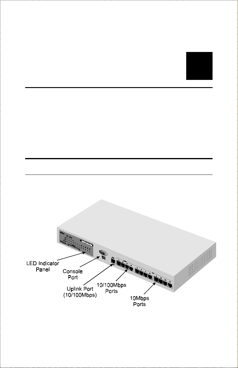
Front Panel
A front view of the DES-2212 Ethernet switch is shown below.
XTERNAL FEATURES
Page 20

♦ LED Indicator Panel Gives status information about the switch
itself, as well as each of the switch ports. The LED indicator panel is
described in detail in the next section.
♦ Console Port The diagnostic console port is a standard RS-232 DB-9
connector, which can be used to connect a terminal or terminal
emulator to the switch, in order to configure or manage the hub . The
port can also be used for out-of-band network management. See the
Using the Console Interface chapter starting on page 21 for complete
information about using the console port.
♦ 100Mbps Ports The 10/100Mbps ports (ports 1 through 4) are
NWay 10BASE-T/100BASE-TX MDI-X ports, suitable for
connecting directly to Et herne t o r Fa st Ethe rnet hosts o r o the r ne twork
equipment. The NWay feature allows the switch to automatically
detect the speed of the network connection.
♦ 10Mbps Ports The 10Mbps ports (p orts 5 thro ugh 12) are 10BASE-
TX MDI-X ports, suitable for connecting directly to Ethernet hosts or
other network equipment.
♦ Uplink Port The Uplink Port is identical to Port 1, except that it is an
MDI port instead of an MDI-X port. This means that you can use it to
connect directly to a Fast Ethernet hub or switch without using a
crossover cable.
Note that the Uplink Port and Port 1 are really the same port, which
means you can’t connect devices to both Port 1 and the Uplink Port at the
same time.
8
External Features
Page 21

LED Indicators
♦ Power Lights when the DES-2212 Ethernet switch is powered on.
♦ Console Lights when the DES-2212 console interface is in use.
♦ MII Lights when the switch’s MII port is being used to connect to a
transceiver. If there is an active connection on the MII port, then the
Link/Act LED for port 2x will also light.
♦ 100M (Ports 1 through 4 ) Lights when the port is operating at
100Mbps. Ports 1 through 4 are NWay ports that can automatically
detect whether 10BASE-T Ethernet or 100BASE-TX Fast Ethernet
twisted-pair cable is connected.
♦ Link/Act (Ports 1 through 12) Lights green when the port is
connected to a powered-on Ethernet/Fast Ethernet station, and blinks
off briefly when information is transmitted or received on the port.
♦ FDX/Col (Ports 1 through 12) Lights green when the port is
operating in full-duplex mode. Briefly blinks amber when a collision
occurs on the Ethernet/Fast Ethernet segment.
♦ System Load Shows a bar graph giving an indication of the network
load, ranging from Low to High.
External Features
9
Page 22
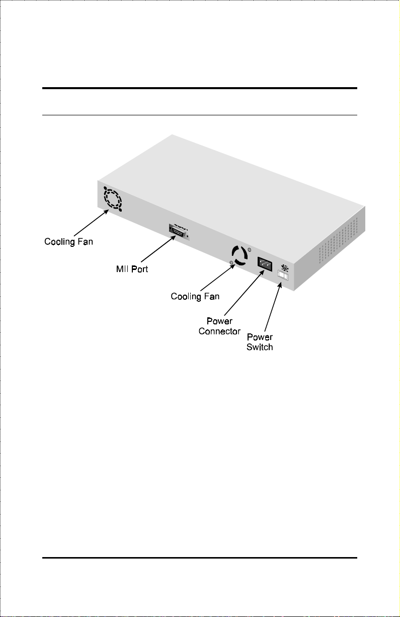
Rear Panel
♦ Cooling Fans Used to control the temperature within the switch’s
enclosure. When installing the switch, be sure not to block the fan
openings or otherwise restrict airflow.
♦ MII Port Used for connecting Fast Ethernet transceivers, which can
be used for attaching other Fast Ethernet media such as 100BASE-FX
(fiber optic) or 100BASE-T4 (4-wire twisted pair).
The MII port is shared with Port 2. If you are using the MII port, then the
10BASE-T/100BASE-TX port labeled 2x cannot be used.
♦ Power Connector Used for connecting the power cord.
10
External Features
Page 23

♦ Power Switch Used to turn the switch on (1 position) or off (0
position).
External Features
11
Page 24

Page 25

6
3 I
This chapter explains how to unpack and install your DES-2212 Ethernet
switch.
NSTALLATION
Unpacking the Switch
Open the shipping carton of your hub and carefully unpack the contents. The
carton should contain the following items:
♦ One DES-2212 Ethernet/Fast Ethernet switch
♦ One AC power cord
♦ Four rubber fee t to be used for shock cushioning
♦ Eight screws and two mounting brackets
♦ This User's Guide
Inspect the switch and all accompanying items. If any item is damaged or
missing, report the problem immediately to your dealer.
Page 26

Installing the Switch
Location
The site where you install the switch may greatly affect its performance.
When installing, consider the following factors:
♦ Install the switch in a cool and dry place. See Appendix A,
Specifications, for the acceptable temperature and humidity operating
ranges.
♦ Install the switch in a site free from strong electromagnetic field
generators (such as motors), vibration, dust, and direct exposure to
sunlight.
♦ Leave at least 10 cm of space at the front and rear of the switch for
ventilation.
♦ Install on a sturdy, level surface that can support at least the weight of
the switch, or in an EIA standard-size rack. For information on rack
installation, see the next section, Rack Mounting.
When installing the switch on a level surface, ensure to attach the rubber feet
at the bottom of the device. The rubber feet act as cushioning devices.
Rack Mounting
The switch can be mounted in an EIA standard 19-inch rack, which can be
placed in a wiring closet with other equipment. Attach the mounting brackets
on the hub’s front panel (one on each side), and secure them with the
provided screws. Then, use screws provided with the equipment rack to
mount the switch in the rack.
14
Installation
Page 27

Connecting Power
The switch features a power supply unit that automatically adjusts to the level
of the input voltage. Supported voltage levels range from 100V to 240V at
50 or 60 Hz. Your local voltage level sho uld fall within this range.
To turn on the DES-2212, plug in the provided AC power cord into the
power connector at the rear of the system, then flip the rocker power switch
to the “1” position. After turning on the power, the Power indicator on the
front panel should light.
It is not necessary to turn off the DES-2212’s power when connecting or
disconnecting network cables (except for the MII port) or console port
connections.
Installation
15
Page 28

Replacing the Fuse
A 2.0A fuse protects the switch’s power supply unit from power surges. In
case of a power surge, the fuse will burn out, thus cutting off the connection
and preventing high voltages from reaching the power supply or the other
sensitive parts of the device. The fuse, and a spare one, are contained in a
fuse case located just beneath the AC power connector. When replacement
becomes necessary, pry open this case with a small screwdriver and replace
the damaged fuse. You may also purchase a new 2.0A fuse, which is readily
available in most local stores.
Fuse
Spare Fuse
WARNING!
16
DO NOT defeat the purpose of the fuse by
using a jumper (such as a wire) in place of a
damaged one. Doing so may cause serious
damage to the hub.
Installation
Page 29

7
4 M
This chapter explains how to connect your switch to network stations, to other
switches or to Ethernet hubs in your network.
AKING
C
ONNECTIONS
N
ETWORK
10BASE-T Connection
Ports 5 through 12 are 10B ASE-T 1 0Mbp s Ethernet p orts that you can use to
connect the switch to network devices using 10BASE-T shielded or
unshielded twisted-pair cable (STP or UTP). The X label marked on each
port means the ports are MDI-X ports, which connect to workstations and
servers using straight-through twisted-pair cables, and to hubs or switches
using crossover cables.
(Ports 1 through 4 are NWay 10/100Mbps ports that can also be used for
10BASE-T connection, provided you don’t need to use the ports for
100BASE-TX).
To connect a network station, use ordinary Ethernet twisted-pair cable,
Category 3 or better , either direc tly or through a central wiring punc h block.
The cable can be at most 100 meters long. Only two wire pairs (four wires)
in the cable are used for 10BASE-T Ethernet.
Page 30

One wire pair should be connected to pins 1 and 2 of the connector, and
another wire pair should be connected to pins 3 and 6. Detailed pinout
information for 10BASE-T/100BASE-TX connectors can be found in
Appendix B.
Plug the RJ-45 connector at one end into the network station, and at the other
end into a free 10BASE-T por t (po rts 5 thr ough 12 ) at the front o f the switch.
When both the switch and the device at the other end of the connection are
turned on, and the cable is connected at both ends, then the Link/Act LED
should light. If it does not, then:
♦ Be sure that the connectors are seated correctly at both ends of the
cable.
♦ Check the continuity of the wires in the cable, as well as the pin
assignments on the RJ-45 connectors.
♦ Be sure that the network station to which the port is connected is
plugged in and powered on.
♦ Be sure that you are using a Category 3 or b etter straight-thr ough (not
crossover) cable.
If you are connecting the switch to an Ethernet hub (or another Ethernet
switch with an MDI-X port), you will need to use a crossover cable. A
crossover cable can be made easily; pinout information for 10BASET/100BASE-TX crossover cables can be found in Appendix FIXME.
100BASE-T Connection
The procedure for connecting 100BASE-TX Ethernet stations to the switch is
the similar to that for 10BASE-T. Cabling for 100BASE-TX should be
certified as Category 5 or better, and should be installed by a professional
cable installer.
18
Making Network Connections
Page 31

User’s Guide
Ports 1 thro ugh 4 are N Way 10/ 100Mbps ports. When you connect a station
to one of these ports, the corresponding port Link/Act LED should light. For
100Mbps connections, the corresponding 100M LED indicator should also
light.
When connecting to a hub or an Ethernet switch with an MDI-X port, you can
use a crossover cable, or you can directly use the Uplink port. You can
connect the uplink port directly to a 100BASE-TX Ethernet hub or switch
using straight-through cable.
NOTE:
Port 1 and the Uplink port are MDI-X and MDI
versions of the same port. If you are using the
Uplink port, you cannot use Port 1, and vice
versa.
MII Connection
The switch’s back panel features an industry-standard MII connector,
allowing you to attach transceivers for other types of 100BASE-X media,
such as 100BASE-FX or 100BASE-T4.
To connect a device using the switch’s MII port,
1. Make sure that the switch is turned off whenever connecting a
transceiver to the MII port (or when removing it).
2. Set the transceiver’s address setting to 2, if it has one. (The MII port
is shared with the switch’s port 2).
3. Attach the transceiver to the MII port at the rear of the switch.
4. Power on the switch. If there is a good link through the transceiver
connected to the MII port, both the MII-II LED and the Link/Act LED
for port 2 should light.
Making Network Connections
19
Page 32

NOTE:
Port 2 and the MII port form one logical port.
Only one of these ports can be used at any
given time.
20
Making Network Connections
Page 33

8
5 U
Your DES-2212 Ethernet switch supports a console management interface
that allows you to set up and control your switch, either with an ordinary
terminal (or terminal emulator), or over the network using the TCP/IP
Telnet protocol. You can use this facility to p erform many basic network
management functions. In addition, the console program will allow you to set
up the switch for management using D-View or another SNMP-based
network management system. This chapter describes how to use the conso le
interface to access the switch, change its settings, and monitor its operation.
SING THE
C
ONSOLE
I
NTERFACE
Connecting to the Switch
You can use the console interface by connecting to the switch using an
ordinary RS-232C serial cable and a VT100-compatible terminal or a
computer running an ordinary terminal emulator program (such as the
terminal program included with the Windows operating system.) Your
terminal parameters will need to be set to:
♦ VT-100/ANSI compatible
♦ Arrow keys enabled
♦ 9600 bits per second
Page 34

♦ 8 data bits
♦ No parity
♦ One stop bit
You can also access the same functions over the
have set an IP add ress for your switch, you can use a
VT-100 compatible terminal mode) to access and control the switch. All of
the screens are for the most part identical, whether accessed from the console
port or from the
Telnet interface.
Telnet interface. Once you
Telnet program (in a
Console Usage Conventions
The console interface makes use of the following conventions:
1. Items after a colon: are read-only values, displayed for information
purposes. The cursor cannot be moved to these items.
2. Items in <angle brackets> can be toggled on or off using the space
bar.
3. Items in [square brackets] can be changed by typing in a new value.
You can use the backspace and delete keys to erase characters behind
and in front of the cursor.
4. The up and down arrow keys, the left and right arrow keys, and the tab
key, can be used to move between selected items. The currently
selected item will be shown in reverse video.
5. Items in UPPERCASE are commands. Moving the selection to a
command and pressing Enter will execute the chosen command.
22
Using the Console Interface
Page 35

User’s Guide
First Time Connecting To The Switch
The Switch supports user-based security that can allow you to prevent
unauthorized users from accessing the Switch or changing its settings. This
section tells how to log onto the Switch.
Note: The passwords used to access the Switch are
case sensitive; therefore, “S” is not the same
as “s.”
When you first connect to the Switch, you will be presented with the first
login screen (shown below).
Figure 6-1. Initial screen, first time connecting to the Switch
Move the cursor to OK and press Enter (Note: Leave the User Name and
Password fields blank). You will see the Main Menu shown below:
Using the Console Interface
23
Page 36

Figure 6-2. Main Menu for Super User
The first user automatically gets super user privileges (See Table 6-1) and
is recommended to create at least one Super User for the Switch.
Steps to create a Super User or General User:
From the screen above, move the cursor to the User Account Change and
press Enter, then the User Account Change Menu appears.
1. Choose Create New User from the User Account Change Me nu and the
Create New User Menu appears.
2. Enter the new user name, and assign an initial password. Determine
whether the new user should have Super User or General User
privileges.
3. Choose SAVE and press Enter to let the user addition take effect.
4. Choose EXIT to leave the Create New User menu.
Super and General User Privileges
There are two levels of user privileges: Super User and General User. Some
menu selections available to users with Super User privileges may not be
24
Using the Console Interface
Page 37

User’s Guide
available to General Users. The main menus shown are the menus for users
with Super User and General User privileges:
Figure 6-3. Main Menu for Super User
Figure 6-4. Main Menu for General User
The following table summarizes Super User and General User privileges:
Menu Super User General User
Privilege
Using the Console Interface
25
Page 38

Menu Super User General User
Privilege
System Config. Yes Yes, view only.
TCP/IP Parameter Configuration Yes Yes, view only.
Statistic Counters Yes Yes .
Port Co nfigur ation Yes Yes, view only.
Spanning Tree Algorithm Parame t ers
Forwarding Table Yes Yes, view only.
Custom Filtering Table Yes Yes, view only.
Protocol Parameters Yes Yes , view only.
STAP Port Parameters Yes Yes, view only.
Out-of-Ba n d/ Conso le Configuration Yes Yes, view only.
User Account Change
Create New User Yes No
Change Access/ Delete Users Yes No
Change Pa ssword Yes Yes
SNMP Tr ap Manager Configurat ion Yes Yes, view only.
SNMP Manager Co nfig. Yes Yes, view only.
System Reset Yes No
Software Update Yes No
Factory Reset NV-RAM to Default Value Yes No
Table 6-1. Super User and General User Privileges
26
Using the Console Interface
Page 39

User’s Guide
establishing a Super User, you are now ready to operate the Switch. Now
issue a LOGOFF command from the main menu, the login scre en
1
appears as
follows.
Login On The Switch Console By
Registered Users
Figure 6-5. Login Screen
To log in,
1. Type in your user name and press Enter.
2. Type in your password and press Enter.
4
If the Switch is not used within five (5) minutes, the following message appears at the bottom
of the console’s main menu: “Console time out press ENTER to continue...” At this time, press
ENTER and login screen will be displayed.
Using the Console Interface
27
Page 40

3. With the cursor on the OK selection, press Enter. The main menu
screen will be displayed based on your Super User or General User
access level or privilege.
The following describes the differences between the user privileges.
Changing your Password
To change your user password:
1. Choose User Account Change from the main menu.
2. Choose
3. Type in your user name and press Enter.
4. Type in your old password and press Enter.
5. Type in the new password you have chosen, and press Enter. Type in
the same new password in the following blank to ver ify that you have
not mistyped it.
6. Choose the SAVE command to let the password change take effect.
Change Password
Figure 6-6. Change Password
.
28
Using the Console Interface
Page 41

User’s Guide
7. Choose EXIT to exit this screen.
This method can also be used by a Super User to change another user’s
password.
Adding and Deleting Users
Access to the console, whether using the console port or via TELNET, is
controlled using a user name and password. Up to three of these user names
can be defined. The console interface will not let you delete the current
logged-in user, however, in order to prevent accidentally deleting all of the
users with Super User privilege.
Only users with the Super User privilege can add new and delete users.
Adding a New User
To add a new user:
1. Choose User Account Change from the main menu.
Figure 6-7. User Account Change Menu
2. Choose Create New User from the User Account Change menu.
Using the Console Interface
29
Page 42

3. Enter the new user name, and assign an initial password. Determine
whether the new user should have Super User or General User
privileges.
Figure 6-8. Adding a New User
4. Choose SAVE and press Enter to let the user addition take effect.
5. Choose EXIT to leave the Create New User menu.
Deleting a User
To delete a user,
1. Choose User Account Change from the main menu.
2. Choose Delete Users from the User Account Change menu.
3. Toggle the Delete field of the user you wish to remove to Yes.
30
Using the Console Interface
Page 43

User’s Guide
Figure 6-9. Deleting a User
4. Choose SAVE and press Enter to let the user addition take effect.
5. Choose EXIT to leave the Delete Users menu.
Setting up the Switch
This section describes the settings you will need to change to allow you to be
able to manage the switch from an SNMP-based Network Management
System such as D-Link’s D-View, or to be able to access the switch using the
Telnet
TCP/IP Settings
The switch needs to have a TCP/IP address assigned to it so that the network
management system or
TCP/IP P arameter s Configura tion Menu a llows you to change the se ttings for
the two different interfaces used on the switch: the Ethernet interface used for
Using the Console Interface
protocol.
Telnet
client can find it on the network. The
31
Page 44

in-band communication, and the SLIP interface used over the console port for
out-of-band communication.
Each of the fields on this menu takes effect the next time the system is
restarted. Fields that can be set include:
♦ IP Address: determines the IP address used by the switch for
receiving SNMP and
Telnet
communications. Should be of the
form xxx.xxx.xxx.xxx, where each xxx is a number (represented in
decimal) between 0 and 255. This address should be a unique address
on a network assigned to you by the central Internet authorities. The
same IP address is shared by both the SLIP and Ethernet network
interfaces.
♦ Subnet Mask: bitmask that determines the extent of the subnet that
the switch is on. Should be of the form xxx.xxx.xxx.xxx, where each
xxx is a number (represented in decimal) between 0 and 255. If no
subnetting is being done, the value should be 255.0.0.0 for a Class A
network, 255.255.0.0 for a Class B network, and 255.255.255.0 for a
Class C network.
♦ Default Gateway: IP address that determines where frames with a
destination outside the current subnet should be sent. This is usually
the address of a router or a host acting as an IP gateway. If your
network is not part of an internetwork, or you do not want the switch
to be accessible outside your local network, you can leave this field
blank.
♦ Send BOOTP Request Upon Power Up: determines whether the
switch should send out a BOOTP broadcast req uest when it is powered
up. The BOOTP protocol allows IP addresses, network masks, and
default gateways to be assigned on a central BOOTP server; if this
option is set the switch will first look for a BOOTP server to provide it
with this information before using the supplied settings.
32
Using the Console Interface
Page 45

User’s Guide
Figure 6-10. TCP/IP Parameters Configuration Menu
Out-of-band management and console
settings
You can use the Out-of-Band/Console Setting menu to choose whether to use
the switch’s RS-232C serial port for console management or for out-of-band
TCP/IP communication using SLIP, and to set the bit rate used for SLIP
communications.
The following fields can be set:
♦ System Restart Out-of-Band Baud Rate: determines the serial port
bit rate that will be used the next time the switch is restarted. Applies
only when the serial port is being used for out-of-band (SLIP)
management; it does not apply when the port is used for the console
port. Available speeds are 2400, 9600, 19200, and 38400 bits per
second.
♦ Out-of-Band Dial Up Phone Number: stored as a reference for the
benefit of the system manager; does not actually cause the switch to
dial out.
Using the Console Interface
33
Page 46

♦ System Restart Serial Port Setting: determines whether the serial
port should be used for out-of-band (SLIP) management or for console
management, starting from the next time the switch is restarted.
Figure 6-11. Out-of-Band/Console Setting Menu
Software Updates
The switch is capable of obtaining its boot-time configuration information, as
well as updated versions of its internal firmware, using TFTP (the Trivial File
Transfer Protocol) and BOOTP (the BOOTstrap Protocol). You can use the
Software Update menu to control this feature.
The fields you can set on this menu are:
♦ Software Update Determines whether or not the switch will try to
look for a configuration file over the network. If set to Disable, none
of the fields below have any effect.
♦ Software Update Mode Set to either Network or Out-of-band.
Determines whether configuration file should be obtained thr ough the
Ethernet network or through the console port.
♦ Boot Protocol Set to either TFTP ONLY or
Applies only if the S/W Update Control is enabled.
34
BOOTP&TFTP.
Using the Console Interface
Page 47

User’s Guide
♦ Boot Server IP Address The IP address of the TFTP server where
the configuration file is located. This entry is used only if the S/W
Update Control is enabled and your boot protocol is
you are using
Power Up is enabled, the address will be obtained from the B OOTP
server.
♦ Boot File Name The pathname of the configuration file on your
TFTP server. If you are using D-View as your TFTP server, this is the
pathname of the
if your boot protocol is TFTP ONLY; if you are using BOOTP&TFTP
mode, or if Use Bootp to get IP after start up is enabled, the pathname
will be obtained from the BOOTP server.
For more information about DES-2212 configuration files, consult the
appendix. For detailed information about using the TFTP and BOOTP
servers, consult the D-View User’s Guide.
bootp-tftp
.CFG
file on your hard disk. This entry is used only
mode, or if Send BOOTP Request on
tftp only
; if
Figure 6-12. Software Update Menu
SNMP Information and Console Timeout
The System Configuration Menu screen shows various pieces of information
about your switch, and allows you to set the System Name, System Location,
and System Contact. These settings can be retrieved from the switch using
Using the Console Interface
35
Page 48

SNMP requests, allowing these settings to be used fo r network management
purposes. Each of these fields can contain up to 64 characters:
♦ System Name: corresponds to the SNMP MIB II variable
system.sysName
administrative purposes. The switch’s fully qualified domain name is
often used, provided a name has been assigned.
♦ System Location: corresponds to the SNMP MIB II variable
system.sysLocation
location of the switch for administrative purposes.
♦ System Contact: corresponds to the SNMP MIB II variable
sysContact
for the person responsible for administering the switch.
, and is used to give a name to the switch for
, and is used to indicate the physical
, and is used to give the name and contact information
Figure 6-13. System Configuration Menu
The System Configuration Menu also contains the Console/Telnet Display
Timeout parameter, which determines how long the console may sit idle
before the user is “logged out.”
36
Using the Console Interface
Page 49

User’s Guide
SNMP Traps
The switch sends out SNMP traps to network management stations whenever
certain exceptional events occur, such as when the switch is powered on or
when an SNMP request is made using an unknown community name. The
switch allows traps to be routed to up to four differ ent network management
hosts.
Figure 6-14. SNMP Trap Manager Configuration Menu
The following trap parameters can be set:
♦ IP Address: gives the IP add ress of the network management station
to receive the trap
♦ SNMP Community String: determines the SNMP community name
to be included in the trap request.
♦ Status: determines whether this trap entry is valid or invalid. You can
delete an entry by changing its status to Invalid.
Using the Console Interface
37
Page 50

SNMP Security (Community Names)
SNMP (version 1) implements a rudimentary form of security by requiring
that each request include a community name. A community name is an
arbitrary string of characters used as a “password” to control access to the
switch. If the switch receives a request with a community name it doesn’t
recognize, it will trigger an authentication trap.
The DES-2212 allows up to four different community names to be defined,
and the access rights for each community can be separately set to either read
only or read/write. The community names
defined by default; you can change these names in addition to adding others.
You will need to coordinate these names with the community name settings
you use in your network management system.
public
and
private
are
Figure 6-15. SNMP Manager Configuration
Switch Configuration
Several important switch parameters useful in the day-to-day management of
the switch can be viewed and controlled using the Port State menu.
38
Using the Console Interface
Page 51

User’s Guide
Controlling Individual Ports
The Port Configuration Menu, accessible from the Network Monitoring
menu, allows you to view the status of individual ports and to control their
settings. The available settings are:
♦ Port Determines which port is displayed.
♦ Port State This toggle determines whether the port should be enab led
or disabled (manually partitioned). Setting the Port State to Disabled
will isolate the port from the rest of the network.
♦ Port Status Shows whether or not there is a good link to a station
connected to the port.
♦ Auto Negotiation Determines whether or not the NWay automatic
speed detection feature is enabled for the port.
♦ Media Speed (100/10Mbps) Displays the transmission speed of the
selected port, either 100 (Ports 1 through 4, 100BASE-TX) or 10
(Ports 5 through 12, 10BASE-T).
♦ Duplex Mode Shows whether the port is operating in half-duplex or
full-duplex mode.
Figure 6-16. Port Configuration Menu
Using the Console Interface
39
Page 52

You can use the PREPORT and NEXPORT commands to switch to another
port. You can also enter the port’s Port ID number.
Forwarding Configuration
The switch monitors all of the Ethernet segments to which it is connected.
Since Ethernet frames include the MAC (Ethernet) address of the originating
station, the switch can automatically learn what segment the frame’s
destination is connected to, and forward the frame to only that segment. (If
the switch hasn’t yet learned what segment a station belongs to, it forwards
the packet to all ports.)
To display the forwarding table, the switch’s current idea of what stations are
attached to what ports,
1. Choose Spanning Tree Algorithm Parameters from the main menu.
2. Choose Forwarding Table.
Figure 6-17. STA, Forwarding Table
The switch removes entries from the forwarding table when they get too
“old.” This permits the hub to adapt when you move a station from one
40
Using the Console Interface
Page 53

User’s Guide
segment to another. You can control the aging time, the amount of time an
entry can be idle before the hub removes it from the forwarding table, by
1. Choose Spanning Tree Algorithm Parameters from the main menu.
2. Choose Custom Filtering Table.
3. Enter the desired age time, in seconds.
Occasionally you may want to manually add entries to the switch’s
forwarding table. To add an entry for a station,
1. Choose Spanning Tree Algorithm Parameters from the main menu.
2. Choose Custom Filtering Table.
Figure 6-18. Custom Filtering Table
3. In the “Source Address” field, enter the Ethernet (MAC) address of the
station, in the form xx:xx:xx:xx:xx:xx; each xx must be a hexadecimal
number between 00 and FF.
4. In the “Source Port” field, type in the port number to which the
station is to be connected. For example: the value “1” in this field
would represent that the station will be connected to port 1 of this
switch; the value “0” would represent that the station can not be
connected to any port of the switch, and the switch will filter out all
packets from the station.
Using the Console Interface
41
Page 54

5. Set the Status of the entry to Permanent in order to enter and save the
settings in the memory of the switch.
6. Choose SAVE to add the entry to the forwarding table.
Spanning Tree Protocol and
Configuration
The DES-2212 implements the IEEE 803.1d Spanning Tree Protocol (STP)
to provide the following functions:
♦ Network loop detection and prevention. There should only be one
path between any two stations on the network. If there is more than
one path, packets will be forwarded in loops forever. The spanning
tree protocol detects any looping paths, and selects the path with the
lowest path cost as the active path, while blocking other paths and
using them as backups.
♦ Automatic topology reconfiguration. If a path for which there is a
backup path fails, the backup path will be automatically activated, and
the spanning tree protocol will automatically reconfigure the network
topology.
STP parameters are mainly used to determine the root bridge and ro ot ports
on the network. If there is a loop in the network, data packets will go through
the root bridge. If the bridge has several ports, then the ro ot p or t will be used
to pass data packets to the root bridge.
STP settings are complex, so you probably want to leave these default
parameter values as they are. If you really need to modify their values, please
refer to the following discussion.
42
Using the Console Interface
Page 55

User’s Guide
Introduction to Spanning Tree Protocol
Parameters
The Spanning Tree Proto col works on two levels: the brid ge (i.e., switch) and
port levels. At the bridge level, the STP algorithm calculates a bridge
identifier for each bridge and then determines the root bridge and the
designated bridges. On the port level, the spanning tree pr otocol determines
the root port and designated ports.
On the bridge level, these terms are used:
♦ Root Bridge The bridge with the lowest-numbered bridge identifier.
The root bridge should be the best bridge among the bridges on the
loop to ensure the highest network reliability and performance.
♦ Designated Bridge A bridge becomes the designated bridge for a
network segment if it has a lower root path cost to the root bridge than
the other bridges on the same segment. If all bridges have the same
root path cost, then the one with the lowest bridge identifier becomes
the designated bridge. Since the root path cost of the root bridge is
zero, the root bridge automatically becomes the designated bridge for
the segments connected onto it.
♦ Bridge Identifier This is a combination of the bridge priority (a
parameter you can set) and the bridge MAC address (a unique,
unchangeable number set at the factory). A lower bridge identifier
results to a higher priority for the bridge, thus increasing its chance of
being selected as the root bridge.
♦ Root Path Cost The root path cost of a bridge is the sum of the path
cost of the port from which a packet is forwarded and the root path
costs of all the bridges the p acket goes thr ough. The r oot p ath cost of
the root bridge is zero.
♦ Bridge Priority This parameter can be set. The smaller the number
you set, the higher the bridge priority is. The higher the bridge
priority, the more chance the bridge has of becoming the root bridge.
Using the Console Interface
43
Page 56

A bridge priority ranges from 0 to 65535, with 0 being the highest
bridge priority.
On the port level, these terms are used:
♦ Root Port. Each bridge has a root port except for the root bridge.
This is the port that has the lowest path cost to the root bridge. In case
there are several such ports, then the one with the lowest port identifier
becomes the root port.
♦ Port Identifier This is a combination of the port priority (a parameter
that can be set) and the physical port number (a unique, unchangeable
number assigned by the bridge).
♦ Designated Port This is the port on each designated bridge that is
attached to the LAN segment for which the bridge is the designated
bridge.
♦ Port Priority This parameter can be set. The smaller the number you
set, the higher the port priority is. The higher the port priority, the
higher the chance the port has for becoming the root port. Port
priority ranges from 0 to 255, with 0 being the highest port priority.
♦ Path Cost Use this parameter to specify preferred paths on the
network. The smaller the path cost, the more chance the port of
becoming the root port. By convention, a 10 Mbps LAN port has a
path cost of 100, while a 100 Mbps port has a path cost of 10.
In the following figure, three DES-2212 switches are used to bridge three
LANs together. Switch 3 is selected as the root bridge because it has the
lowest bridge ID. Switch 3, as the root bridge, also becomes the designated
bridge for LANs 1 and 3. Switch 1 becomes the designated bridge for LAN
2.
Only designated bridges ha ve designated ports, so Switch 2 does not have any
designated ports. Port 2 of Switch 2 becomes the root port because it has a
lower root path cost to the root bridge than Port 1. Fo r Switch 1, Port 1 is the
root port, while Port 2 is the designated port. For Switch 3, both ports are
designated ports.
44
Using the Console Interface
Page 57

User’s Guide
The Spanning Tree Protocol puts all root ports and designated ports in the
forwarding state, while placing the others in the blocking state.
LAN 1
Bridge ID = 21
Switch 1
12
LAN 2
Switch 2
12
Switch 3
Bridge ID = 15
Bridge ID = 30
12
LAN 3
Setting Spanning Tree Protocol
Parameters
To set the STP bridge parameters for the switch,
1. Choose Spanning Tree Algorithm Parameters from the main menu.
2. Choose Protocol Parameters from the Spanning Tree Algorithm
Parameters menu.
3. The Protocol Parameters menu displays the current status of the
Spanning Tree Algorithm’s operation on the DES-2212, and allows
you to change several of the bridge parameters. All of these settings
are described below.
Using the Console Interface
45
Page 58

Figure 6-19. Protocol Parameters Menu
4. Choose SAVE and press Enter to let any changes take effect.
The status variables shown are:
♦ Time Since Topology Change The last time that changes were made
to the network topology, such as might occur when a backup path is
activated due to a primary path failure.
♦ Topology Change Count How many times the network bridge
topology has changed since the DES-2212 was turned on.
♦ Designated Root The MAC (Ethernet) address of the bridge/switch
on the network that has been chosen as the STA root.
♦ Root Cost Displays the cost for the path between this switch and the
root bridge. If the DES-2212 is the root bridge, then this field displays
zero.
♦ Root Port Identifies the port (on this bridge) that offers the least path
cost from this bridge to the root bridge. In the event of a network
loop, data packets will pass through the root port.
♦ Max Age (sec) Indicates the maximum age of spanning tree
information learned from the network (on any port) before it is
discarded.
46
Using the Console Interface
Page 59

User’s Guide
♦ Forward Delay (sec) Indicates how fast any port on the DES-2212
can change its spanning state when moving towards the forwarding
state. This value determines how long the port stays in each of the
listening and learning states, which precede the forwarding state.
♦ Bridge Max Age When the value you set for this parameter expires,
and the DES-2212 still has not received a BPDU from the root bridge,
it will start sending its own BPDU to all other bridges for permission
to become the root bridge. If it turns out that the DES-2212 has the
lowest bridge identifier, it will then become the root bridge. Bridge
Max Age ranges from 6 to 40 seconds, with 20 seconds as the default
value.
♦ Bridge Hello Time This is the interval between two consecutive
transmissions of BPDU packets sent by the root bridge to inform all
other bridges that it is indeed the root bridge. If you set a Bridge
Hello Time for a bridge that is not the root bridge, the setting will be
used if and when this bridge becomes the root bridge. Bridge Hello
Time ranges from 1 to 10 seconds, with 2 seconds as default.
♦ Bridge Forward Delay. Bridge Forward Delay ranges from 4 to 30
seconds. This is the time any port on the DES-2212 spends in the
“listening state” while moving from “blocking state” to “forwarding
state”.
Use the following formulas when setting this parameter:
Bridge Max Age ≥ 2 · (Bridge Hello Time + 1 second)
Bridge Max Age ≤ 2 · (Bridge Forward Delay - 1 second)
♦ Bridge Priority FIXME This parameter sets the priority number of
the system. Valid value ranges from 0 to 65535, with 0 being the
highest bridge priority. Default value is 32768.
To set the STP port parameters for the switch,
1. Choose Spanning Tree Algorithm Parameters from the main menu.
Using the Console Interface
47
Page 60

2. Choose Port Parameters from the Spanning Tree Algorithm
Parameters menu.
3. Select the port number that you wish to set parameters for.
4. The Protocol Parameters menu displays the current status of the port
concerning the Spanning Tr ee Algorithm’s operation, and allo ws you
to modify some of the parameters.
Figure 6-20. STAP Port Parameters
♦ State Indicates the current state of the port. A port can have the
following states: Disabled, Blocking, Listening, Learning,
Forwarding, and Broken. A broken state means that the link on the
port has been broken because the port is malfunctioning. Blocking
means that the port has been blocked because it is neither a root port
nor a designated port. In STP, only root and designated ports are
used.
♦ Designated Root Indicates the MAC (Ethernet) address of the
switch/bridge that is the STP designated root for the network.
♦ Designated Cost Displays the path cost from this port to the
designated root.
48
Using the Console Interface
Page 61

User’s Guide
♦ Designated Bridge Displays the MAC address of the switch/bridge
that is the designated bridge for the segment to which the port is
attached.
♦ Designated Port This is the port on each designated bridge that is
attached to the LAN segment for which the bridge is the designated
bridge
♦ Port Path Cost (1–65535) Allows you to specify a path cost for the
port. By convention, 10Mbps ports are given a path cost of 100, and
100Mbps ports are given a path cost of 10.
♦ Port Priority (0–255) Allows you to set a priority for the port. The
priority is used in conjunction with the physical port number to
compute the port ID used for selecting the root port. The lower the
port ID, the more likely the port is to become the root port.
Monitoring the Switch
The switch supports several monitoring functions, allowing you to keep
statistics on the operation of each port.
Displaying Port Statistics
The switch collects Ethernet transmission statistics for each individual port.
All counters start at 0 when you enter the statistics display. The statistics
displayed are:
♦ MAC Rx Errors Counts receive errors occurring on the port.
♦ CRC Errors Counts otherwise valid frames that fail the CRC check.
♦ Oversize Frames Counts frames longer than the 1518-byte (octet)
limit set by the Ethernet standard. This is likely caused by a software
problem.
Using the Console Interface
49
Page 62

♦ Fragments Counts packets less than 64 bytes with either bad framing
or an invalid CRC. These are normally the result of collisions.
♦ Jabber Frames Counts frames with length more than 1518 bytes and
with CRC error or misaligned (b ad framing).
♦ Collision Counts collisions on the Ethernet segment.
♦ Late Collisions The number of collisions that occurred at or after the
th
byte (octet) in the frame.
64
♦ Bytes Tx Counts the number of bytes successfully sent from the port.
♦ Bytes Rx: Counts the number of bytes successfully received at the
port. This also includes local and dropped packets.
♦ Total Octs Rx: Counts the number of bytes (octets) received on the
port, in both good frames and error frames.
♦ Multicast Rx Frames Counts the number of good multicast frames
received. This includes local and dropped multicast packets.
♦ Broadcast Rx Frames Counts the number of good broadcast frames
received. This includes local and dropped broadcast packets.
♦ Rx (Good) Frames Counts the number of good frames received.
This also includes local and dropped packets.
♦ Tx (Good) Frames Counts the number of good frames sent from the
respective port.
♦ 64 Octs, 65-127 Octs, 128-255 Octs, 256-511 Octs, 512-1023 Octs,
1024-1518 Octs Counts frames of various length ranges, b oth valid
and invalid.
♦ Total Rx Frames Counts the number of frames received, both good
frames and error.
50
Using the Console Interface
Page 63

User’s Guide
Figure 6-21. Statistics Counters
You can use the PREPORT, and NEXTPORT commands to switch ports.
The CLEAR COUNTER command will start all of the counters over at 0.
Resetting the Switch
You can use the console interface to reset the switch, either doing a System
Reset (which restarts the switch and is identical to powering the hub off and
back on again) or a Factory Reset (which sets all of the switch’s parameters to
what they were when the switch was delivered from the factory).
System Reset
To perform a system reset,
1. Choose System Reset from the main menu.
Using the Console Interface
51
Page 64

Figure 6-22. System Reset
2. Move the cursor to Yes to confirm the reset and press Enter. The
switch should restart.
Factory Reset
Before performing a factory reset, be absolutely certain that this is what you
want to do. Once the reset is done, all of the switch’s settings stored in
NVRAM (including TCP/IP parameters, SNMP parameters, the
enabled/disabled settings of ports, security settings, etc.) will be erased and
restored to their factory default settings.
1. Choose Factory Reset NV-RAM to Default Value from the main
menu.
52
Using the Console Interface
Page 65

User’s Guide
Figure 6-23. Factory Reset
2. Move the cursor to Yes to confirm the reset and press Enter. The
switch should restart, and all of its parameters will be reset to their
default values.
Using the Console Interface
53
Page 66

Page 67

$
6 P
S
PECIFICATIONS
RODUCT
General
Standards: IEEE 802.3 10BASE-T Ethernet, IEEE 802.3u 100BASE-TX
Fast Ethernet Class II repeater; ANSI X3T9.5 Twisted-Pair Transceiver
Topology: Star
Protocol: CSMA/CD
Network Data Transfer Rate: 10Mbps/100Mbps
Number of Ports: 8 10BASE-T ports, 4 10BASE-T/100BASE-TX NWay
ports
Network Media: 10BASE-T: UTP Cat 3/4/5, 100-ohm unshielded twisted
pair (100m max.); 100BASE-TX: UTP Cat 5, 100-ohm unshielded twistedpair (100m max.).
Page 68

LED Indicators
Switch Status LEDs: Power, System Load bar graph
Port Status LEDs: 100M, Link/Activity, Full Duplex/Collision
Environmental and Physical
Power Supply: 100 to 240 VAC, 50 or 60 Hz internal universal power
supply
Power Consumption: 40 watts max.
Dimensions: 441mm × 207mm × 43mm (1U height), 19-inch rack-
mountable
Weight: approx. 3kg
Operating Temperature: 0 to 50°C
Storage Temperature: –20 to 55°C
Humidity: 5% to 95% non-condensing
DC Fans: two 40mm × 40mm
Emissions: FCC Class A, CE Mark, VCCI Class 1
Safety: UL, CSA, TUV/GS
56
Product Specifications
Page 69

%
7 C
C
This appendix describes the pinouts of the switch’s cables and connectors.
ABLES AND
ONNECTORS
10BASE-T/100BASE-TX Connectors
Ports 1 thro ugh 4 are MDI-X 10 BASE-T/100BASE-TX Ethernet ports with
NWay capability, allowing them to automatically detect port speed. The
Uplink port is identical to Port 1x, excep t that it has an MDI pinout instead.
(You cannot use Port 1x and the Uplink port at the same time.)
Ports 5 through 12 are MDI-X 10BASE-T Ethernet ports.
10BASE-T/100BASE-TX connection requires a twisted-pair cable, at most
100 meters long, with RJ-45 connectors at both ends. You can use shielded
twisted-pair cable or 0.4-0.6 mm (22-26 AWG) 8-wire unshielded twistedpair cable for the connection. 100BASE-TX connection requires Category 5
twisted-pair cabling.
The following diagram and table show the standard RJ-45
receptacle/connector and their pin assignments. Numbering of the pins and
contacts shown in the diagram correspond to the entries in the subsequent
table. Only pin/contact signals relevant to the switch are listed.
Cables and Connectors
57
Page 70

(
)
)
RJ-45 Connectors
RJ-45 Connector
Contact MDI-X Signal MDI Signal
1 RD+ (receive) TD+ (transmit)
2 RD- (receive) TD- (transmit)
3 TD+ (transmit) RD+ (receive)
4 Not used
5 Not used
6 TD- (transmit) RD- (receive)
7 Not used
8 Not used
Workstation
MDI
TD+
TD-
2
3
RD+
6
RD-
Straight-through Cable
RD+11
RD-
TD+
TD-
Switch (MDI-X
2
3
6
58
Cables and Connectors
Page 71

Crossover Cable
(
)
)
When cascading or connecting the hub to another switch, bridge, or hub
through the UTP port, a modified crossover cable is necessary. With a
crossover cable, two pairs of wires are switched at one connector end. Carry
out the following steps to create a customized, crossover twisted-pair cable:
1. Leave one end of the cable as is, with the RJ-45 connector intact. The
wiring at just one end of the cable needs to be modified.
2. At the other end of the cable, connect wires 1 and 2 to contacts 3 and 6
respectively. Likewise, connect wires 3 and 6 to contacts 1 and 2.
Refer to the following diagram:
Hub
MDI-X
RD+
RD-
2
3
TD+
6
TD-
RD+11
RD-
TD+
TD-
Switch (MDI-X
2
3
6
Crossover Cable
MII Connector
The MII (Media-Independent Interface) is a standard 40-pin connector that
you can use to connect other types of 100Mbps network media to your DES-
2212. Using a transceiver connected to the MII port on the rear panel of
your switch, you can connect the switch to a 100BASE-FX or 100BASE-T4
link.
This appendix shows the pin assignments for the MII connector, which is
specified in the IEEE 802.3u Fast Ethernet standard.
Cables and Connectors
59
Page 72

MII Connector Pin Assignment
Contact MII Signal Signal Name Contact MII Signal Signal Name
1 +5 V Voltage 21 +5 V Voltage
2 MDIO MAC Data
Input Output
3 MDC MAC Data
Clock
4 RXD<3> Receive Data
3 bit
5 RXD<2> Receive Data
2 bit
6 RXD<1> Receive Data
1 bit
7 RXD<0> Receive Data
0 bit
8 RX_DV Receive Data
Valid
9 RX_CLK Receive
Clock
10 RX_ER Receive Error 30 --- Ground
11 NOT USED Not Used 31 --- Ground
12 TX_CLK Transmit
Clock
13 TX_EN Transmit
Enable
14 TXD<0> Transm i t Data
0 bit
15 TXD<1> Transm i t Data
1 bit
16 TXD<2> Transm i t Data
2 bit
17 TXD<3> Transm i t Data
3 bit
18 COL Collision 38 --- Ground
19 CRS Carry Sense 39 --- Ground
22 --- Ground
23 --- Ground
24 --- Ground
25 --- Ground
26 --- Ground
27 --- Ground
28 --- Ground
29 --- Ground
32 --- Ground
33 --- Ground
34 --- Ground
35 --- Ground
36 --- Ground
37 --- Ground
60
Cables and Connectors
Page 73

MII Connector Pin Assignment
C
S
C
Contact MII Signal Signal Name Contact MII Si gnal Signal Name
20 +5 V Volt age 40 +5 V V ol t age
RS-232 (DB9) Pin Specification
The RS-232 serial port of the hub uses a 9-pin female connector. The port can
be connected to a VT-100 type terminal, a PC, or a workstation emulating a
VT-100 terminal. The connection can be either local, or remote through a
modem. For a remote connection, a modem cable with a 9-pin male connector
on the hub side is needed. The figures below show the connections necessary
for local and remote connection to 9-pin and 25-pin RS-232 devices.
onsole P ort
(D C E , D B -9 )
DCD (1)
RXD (2)
TxD (3)
DTR (4)
SG (5)
DSR (6)
RTS (7)
CTS (8)
Terminal/P
erial P ort
(D T E, D B -9)
DCD (1)
RXD (2)
TxD (3)
DTR (4)
SG (5)
DSR (6)
RTS (7)
CTS (8)
-(9)
Local Connection to 9-Pin Serial Port
-(9)
Cables and Connectors
61
Page 74

C
S
C
onsole P ort
C
(D C E, D B -9)
Terminal/P
(D T E , D B -2 5 )
erial Port
DCD (1)
RXD (2)
TxD (3)
DTR (4)
SG (5)
DSR (6)
RTS (7)
CTS (8)
-(9)
Local Connection to 25-Pin Serial Port
onsole P ortConnector
(DCE, DB-9)
DCD (1)
RXD (2)
TxD (3)
DTR (4)
SG (5)
DSR (6)
RTS (7)
CTS (8)
-(9)
DCD (8)
RXD (3)
TxD (2)
DTR (20)
SG (7)
DSR (6)
RTS (4)
CTS (5)
Modem
(D C E, D B -9 )
DCD (1)
RXD (2)
TxD (3)
DTR (4)
SG (5)
DSR (6)
RTS (7)
CTS (8)
-(9)
62
Remote (Modem) Connection to 9-Pin Serial Port
Cables and Connectors
Page 75

C
onsole P ort
(D C E, D B -9)
Modem
(DCE, D B-25)
DCD (1)
RXD (2)
TxD (3)
DTR (4)
SG (5)
DSR (6)
RTS (7)
CTS (8)
DCD (8)
RXD (3)
TxD (2)
DTR (20)
SG (7)
DSR (6)
RTS (4)
CTS (5)
-(9)
Remote (Modem) Connection to 25-Pin Serial Port
Cables and Connectors
63
Page 76

Page 77

&
8 B
The switch supports a powerful configuration file which allows many of the
switch’s configuration parameters to be stored on a centralized server. When
the switch starts up, it can be configured to read its configuration file from the
server using the TFTP protocol. This can make it easier to manage a large
number of switches, since all of the configuration parameters for all of the
switches can be managed in a single place.
The configuration file is a text file, usually stored on the server with a
extension. It can be up to 10 kilobytes long. Lines beginning with # are
considered comments which are ignored by the hub. All other lines are
commands, which are interpreted by the switch.
The configuration file commands accepted by the hub are:
sysdescr
♦
Takes string as the System Name, corresponding to the SNMP MIB II
variable
switch for administrative purposes. The switch fully qualified domain
name is often used, provid ed a name has been assigned. The string can be
up to 64 characters long.
OOT
string
system.sysName
C
ONFIGURATION
F
. This field is used to give a name to the
ILE
.CFG
syscontact
♦
string
Page 78

Takes string as the System Contact, corresponding to the SNMP MIB II
variable
information for the person responsible for administering the switch. The
string can be up to 64 characters long.
sysContact.
This field is used to give the name and contact
syslocation
♦
Takes string as the System Location, corresponding to the SNMP MIB II
variable
location of the switch for administrative purposes. The string can be up to
64 characters long.
baud-rate
♦
Sets the console port transmission rate used when the port is being used in
out-of-band mode. Legal values for the parameter n are: 2400, 4800,
9600, 19200, and 38400.
image-file
♦
Takes string (which may be up to 64 characters long) as the filename on
the TFTP server of the image file to be used. When the switch boots, it
will load the given image file from the server and execute it. This
command may be used to update the switch’s software when a new
version is available from D-Link.
ip-netmask
♦
Uses mask as the network mask for the local network. The mask should
be in the form xxx.xxx.xxx.xxx, where each xxx is a number between 0 and
255. For a class C network with no subnetting, the netmask should be
255.255.255.0.
sysLocation.
string
This field is used to indicate the physical
n
string
mask
ip-default
♦
Uses address as the hub’s IP address. The address should be in the form
xxx.xxx.xxx.xxx, where each xxx is a number between 0 and 255.
auth-trap
♦
66
address
enable/disable
Boot Configuration File
Page 79

Enables or disables authentication failure traps for invalid SNMP
community names. The argument may be
clear-SNMP-comm-table
♦
Clears the hub’s SNMP community name table.
enable
disable
or
.
SNMP-community
♦
Adds community to the switch’s list of SNMP communities, with access
permissions. The community name can be up to 32 characters long.
Permissions can be
for read-write community access.
clear-ip-trap-manager-table
♦
Removes all entries from the switch’s trap manager list.
ip-trap-manager
♦
Adds the host at address to the switch SNMP trap manager list. Traps
sent to the host will use community name community, which may be a
string up to 32 characters long.
PFT-Entry
♦
Adds entries to the switch’s forwarding table. The mac-address
corresponds to the source Ethernet address, in the form xx:xx:xx:xx:xx:xx.
The recv-port is the port from which packets from the station may be
received. The allowed-ports field lists the ports to which packets from the
station may be forwarded, separated by slashes.
mac-address recv-port allowed-ports
community permissions
read
, for read-only community access, or
address community
write
,
Boot Configuration File
67
Page 80

9 I
NDEX
100BASE-FX, 21, 63
100BASE-T4, 21, 63
100M LED, 21
100M LEDs, 11
19-inch rack, 16
Adding a New User, 31
Adding and Deleting Users, 31
address, Ethernet, 2
age time, 44
brackets, 15
bridge identifier, 46
bridge priority, 47
broadcast RX frames statistic counter, 54
buffer memory, 2
bytes RX statistic counter, 54
bytes TX statistic counter, 54
Changing your Password, 30
Class I Fast Ethernet repeater, 5
Class II Fast Ethernet repeater, 5
collision domain, 5
collision domains, 6, 7
Collision statistic counter, 54
collisions, 11
Console LED, 11
console port, 10
cooling fans, 12
CRC Errors statistic counter, 53
Deleting a User, 33
designated bridge, 46, 52
designated cost, 52
designated port, 46, 47, 52
designated root, 50, 52
factory reset, 56
FDX/Col LEDs, 11
feet, rubber, 15, 16
fiber optic cable, 1
forwarding table, 2, 43, 44
Fragments statistic counter, 53
front panel, 9
full-duplex mode, 2, 11
fuse, 18
General User, 27
half-duplex mode, 2
inter-repeater link, 5
jabber frames statistic counter, 54
late collisions statistic counter, 54
LED indicator panel, 10
Link/Act LED, 21, 22
Link/Act LEDs, 11, 20
Logging In on the Console Screen, 25
Logging In on the Switch Console, 25
MAC address, 2
MAC address level, 6
MAC Rx Errors statistic counter, 53
maximum age, 50
Media-Independent Interface. See MII
MII, 1, 21, 63
MII LED, 11, 22
MII port, 12, 22
multicast RX frames statistic counter, 54
NVRAM, 56
NWay, 1, 10, 11, 21, 42
Oversize Frames statistic counter, 53
path cost, 47
68
Index
Page 81

port identifier, 47
port path cost, 53
port priority, 47, 53
Port State, 52
ports, 100Mbps, 10
ports, 10Mbps, 10
ports, MII, 12
power connector, 12
power cord, 15
Power LED, 11, 17
power supply, 17
power switch, 13, 17
Prevent Unauthorized Users, 25
rack mounting, 16
reset, factory, 56
reset, system, 55
root bridge, 46
root cost, 50
root path cost, 47
root port, 46, 47, 50
RX (good) frames statistic counter, 54
segments, 6
SNMP, 2
Spanning Tree Protocol, 2, 45
static filtering, 2
statistic counters, 53
store-and-forward, 2
STP. See Spanning Tree Protocol
Super and General User Privileges, 27
Super User, 27
switch, 6
Switching LAN technology, 7
switching technology, 6
System Load bar graph LEDs, 11
system reset, 55
topology change count, 50
topology change, time since last, 49
total octets RX statistic counter, 54
Total Rx Frames statistic counter, 54
Tx (Good) Frames statistic counter, 54
unshielded twisted-pair, 4
uplink port, 2, 10
Page 82

Page 83

Offices
U.S.A. D-LINK SYSTEMS, INC.
CANADA D-LINK CANADA, INC.
U.K. D-LINK (EUROPE) LTD.
GERMANY D-LINK (DEUTSCHLAND) GMBH I.G.
FRANCE D-LINK FRANCE
SWEDEN D-LINK A/B
DENMARK D-LINK DENMARK
SINGAPORE D-LINK SINGAPORE PTE.LTD.
AUSTRALIA D-LINK AUS TRALIA PTY.LTD.
CHINA D-LINK BEIJING
JAPAN D-LINK TOKYO
INDIA D-LINK (INDIA) PVT. LTD.
TAIWAN D-LINK TAIWAN
5 Musick Irvine, CA 92618 USA
TEL: 1-714-455-1688 FAX: 1-714-455-2521
2180 Dunwin Drive, Unit # 6,
Mississauga Ontario, L5L 5M8, Canada
TEL: 1-905-828-0260 FAX: 1-905-828-5669
D-Link House, 6 Garland Road, Stanmore, London HA7 1DP U.K.
TEL: 44-181-235-5555 FAX: 44-181-235-5500
Bachstraße 2265812 65830 Kriftel, Germany
TEL: 49-6192-97110 FAX: 49-6192-971111
Le FLORILEGE #2, Allee de la Fresnerie
78330 Fontenay Le Fleury France
TEL: 33-1-30238688 FAX: 33-1-30238689
World Trade Center P. O. Box 70396, 107 24 Stockholm Sweden
TEL: 46-8-700.62.11 FAX: 46-8-21.96.40
Naverland 2 DK-2600 Glostrup Copenhagen, Denmark
TEL: 45-43-96.90.40 FAX: 45-43-42.43.47
77 Science Park Drive #03-03 CINTECH III,
Singapore Science Park Singapore 118256
TEL : 65-774-6233 FAX: 65-774-6322
Unit 16, 390 Eastern Valley Way Roseville, NSW 2069 Australia
TEL: 61-2-9417-7100 FAX: 61-2-9417-1077
15th Floor, Science and Technology Tower
No. 11, Baishiqiao Road, Haidian District, Beijing 100081 China
TEL: 86-10-68467106/68467107/68467108/68467109 FAX: 86-10-68467110
5F, 3-9-1 Togoshi, Shinagawa-ku Tokyo 142 Japan
TEL: 81-3-5751-2351 FAX: 81-3-5751-2352
Plot No.5, Kurla-Bandra Complex Rd.
Off Cst Rd., Santacruz (E) Bombay - 400 098 India
TEL: 91-22-611-2788/617-2478-80/611-2948 FAX: 91-22-611-3503/617-2476
2F, No.233-2 Pao-Chiao Rd, Hsin-Tien, Taipei,Taiwan, R.O.C.
TEL: 886-2-916-1600 FAX: 886-2-914-6299
Page 84

Page 85

Registration Card
Print, type or use block letters.
Your name: Mr./Ms_____________________________________________________________________________
Organization: ________________________________________________Dept. ____________________________
Your title at organization:________________________________________________________________________
Telephone:_______________________________________ Fax:________________________________________
Organization's full address: ______________________________________________________________________
____________________________________________________________________________________________
Country: _____________________________________________________________________________________
Date of purchase (Month/Day/Year):_______________________________________________________________
Product Model Product Serial
No.
(* Applies to adapters only)
Product was purchased f rom:
Reseller's name: ______________________________________________________________________________
Telephone:_______________________________________ Fax:________________________________________
Reseller's full address: _________________________________________________________________________
_________________________________________________________________________
_________________________________________________________________________
Answers to the following questions help us to support your product:
1.Where and how will the product primarily be used?
†Home †Office †Travel †Company Business †Home Business †Personal Use
2. How many employees work at installation site?
†1 employee †2-9 †10-49 †50-99 †100-499 †500-999 †1000 or more
3. What network protocol(s) does your organization use ?
†XNS/IPX †TCP/IP †DECnet †Others_____________________________
4. What network operating system(s) does your organization use ?
†D-Link LANsmart †Novell NetWare † NetWare Lite †SCO Unix/Xenix †PC NFS †3Com 3+Open
†Banyan Vines †DECnet Pathwork †Windows NT †Windows NTAS †Windows '95
†Others__________________________________________
5. What network management program does your organization use ?
†D-View †HP OpenView/Windows †HP OpenView/Unix †SunNet Manager †Novell NMS
†NetView 6000 †Others________________________________________
6. What network medium/media does your organization use ?
†Fiber-optics †Thick coax Ethernet †Thin coax Ethernet †10BASE-T UTP/STP
†100BASE-TX †100BASE-T4 †100VGAnyLAN †Others_________________
7. What applications are used on your network?
†Desktop publishing †Spreadsheet †Word processing †CAD/CAM
†Database management †Accounting †Others_____________________
8. What category best describes your company?
†Aerospace †Engineering †Education †Finance †Hospital †Legal †Insurance/Real Estate †Manufacturing
†Retail/Chainstore/Wholesale †Government †Transportation/Utilities/Communication †VAR
†System house/company †Other________________________________
9. Would you recommend your D-Link product to a friend?
†Yes †No †Don't know yet
10.Your comments on this product?
__________________________________________________________________________________________
__________________________________________________________________________________________
* Product installed in type of
computer (e.g., Compaq 486)
* Product installed in
computer serial No.
Page 86

 Loading...