

D-Link DES-2110 User Manual

DES-2110
8-port 10/100 + 1-port 1000Base-T Copper
+ 1-port miniGBIC Gigabit Switch
User’s Guide


FCC Warning
This equipment has been tested and found to comply with the limits
for a Class A digital device, pursuant to Part 15 of the FCC Rules.
These limits are designed to provide reasonable protection against
harmful interference when the equipment is operated in a commercial
environment. This equipment generates, uses, and can radiate radio
frequency energy and, if not installed and used in accordance with this
user’s guide, may cause harmful interference to radio communications.
Operation of this equipment in a residential area is likely to cause
harmful interference in which case the user will be required to correct
the interference at his own expense.
CE Mark Warning
This is a Class A product. In a domestic environment, this product
may cause radio interference in which case the user may be required
to take adequate measures.
VCCI Warning


i
TABLE OF CONTENTS
About This Guide ................................................................................ 1
Terms ........................................................................................... 1
Overview of this User’s Guide ....................................................1
Introduction.......................................................................................... 3
Fast Ethernet Technology ............................................................ 3
Gigabit Ethernet Technology....................................................... 3
Switching Technology ................................................................. 4
Switch Description....................................................................... 5
Features........................................................................................ 6
Ports ............................................................................................. 8
Unpacking and Setup........................................................................... 9
Unpacking.................................................................................... 9
Setup ............................................................................................ 9
Installing the Switch on a Desktop ............................................ 10
Installing the Switch on a Rack ................................................. 11
Power on .................................................................................... 12
Identifying External Components...................................................... 13
Front Panel Components............................................................ 13
Rear Panel .................................................................................. 14

ii
LED Indicators........................................................................... 14
Power and CPU LEDs ............................................................... 15
Ports 1~8, 10/100M Fast Ethernet Ports Status LEDs............... 15
Port 9, Gigabit Ethernet Port Status LEDs................................. 16
Port 10, mini-GBIC Port Status LEDs ....................................... 16
Introduction To Switch Management ................................................ 17
Management Options................................................................. 17
Web Management Utility........................................................... 17
Web-based Management Interface.............................................17
Command Line Interface (CLI) ................................................. 18
SNMP-Based Management........................................................ 18
Configuration The Switch.................................................................. 19
Web Management Utility........................................................... 19
Installing the Web Management Utility ............................. 19
Discovery List.................................................................... 20
Monitor List ....................................................................... 21
Device Setting.................................................................... 23
Toolbar............................................................................... 25
Configuring the Switch using Web Browser ............................. 26
Login to Web Manager ...................................................... 27

iii
Setup Menu........................................................................ 30
Configuring Setup Setting.................................................. 31
VLAN Settings (Virtual Local Area Network).................. 33
Mirror Setting .................................................................... 36
Spanning Tree Setting........................................................ 37
SNMP Setting .................................................................... 39
Static MAC ........................................................................ 45
IGMP Snooping Setting..................................................... 47
Device Status .....................................................................49
Statistic............................................................................... 50
System Setting ................................................................... 51
Trap Setting........................................................................ 52
Set Password ...................................................................... 53
Backup Setting................................................................... 54
Reset Setting ...................................................................... 54
Logout................................................................................ 55
Configuring the Switch using the CLI....................................... 56
IP Address of the Switch.................................................... 56
Using the CLI via Telnet interface..................................... 57
Command Syntax............................................................... 58

iv
Basic Switch Commands ................................................... 60
Basic IP Commands........................................................... 65
Switch Port Commands...................................................... 67
VLAN Commands ............................................................. 71
Port Mirroring Commands................................................. 79
Trap Commands................................................................. 82
Spanning Tree Commands................................................. 87
SNMP Commands ............................................................. 95
IGMP Snooping Commands ............................................ 102
Technical Specifications .................................................................. 108

1
ABOUT THIS GUIDE
This user’s guide tells you how to install your DES-2110, how to
connect it to your network.
Terms
For simplicity, this documentation uses the terms “Switch” (first letter
upper case) to refer to the DES-2110, and “switch” (first letter lower
case) to refer to all Ethernet switches, including the DES-2110.
Overview of this User’s Guide
Introduction
Describes the Switch and its features.
Unpacking and
Setup
Helps you get started with the basic
installation of the Switch.
Identifying
External
Components
Describes the front panel, rear panel, and
LED indicators of the Switch.
Configuration
the Switch
Tell to how to configuration the
management functions of the Switch.
Technical
Specification
Lists the technical specifications of the
Switch.


3
INTRODUCTION
This section describes the features of the DES-2110, as well as giving
some background information about Gigabit Ethernet, Fast Ethernet
and Switching technology.
Fast Ethernet Technology
The growing importance of LANs and the increasing complexity of
desktop computing applications are fueling the need for high
performance networks. A number of high-speed LAN technologies
are proposed to provide greater bandwidth and improve client/server
response times. Among them, Fast Ethernet, or 100BASE-T, provides
a non-disruptive, smooth evolution from 10BASE-T technology.
100Mbps Fast Ethernet is a standard specified by the IEEE 802.3
LAN committee. It is an extension of the 10Mbps Ethernet standard
with the ability to transmit and receive data at 100Mbps, while
maintaining the Carrier Sense Multiple Access with Collision
Detection (CSMA/CD) Ethernet protocol.
Gigabit Ethernet Technology
Gigabit Ethernet is an extension of IEEE 802.3 Ethernet utilizing the
same packet structure, format, and support for CSMA/CD protocol,
full duplex, flow control, and management objects, but with a tenfold
increase in theoretical throughput over 100Mbps Fast Ethernet and a
one hundred-fold increase over 10Mbps Ethernet. Since it is
compatible with all 10Mbps and 100Mbps Ethernet environments,
Gigabit Ethernet provides a straightforward upgrade without wasting
a company's existing investment in hardware, software, and trained

4
personnel. The increased speed and extra bandwidth offered by
Gigabit Ethernet are essential to coping with the network bottlenecks
that frequently develop as computers and their busses get faster and
more users use applications that generate more traffic. Upgrading key
components, such as your backbone and servers to Gigabit Ethernet
can greatly improve network response times as well as significantly
speed up the traffic between your sub-networks. Gigabit Ethernet
enables fast optical fiber connections to support video conferencing,
complex imaging, and similar data-intensive applications. Likewise,
since data transfers occur 10 times faster than Fast Ethernet, servers
outfitted with Gigabit Ethernet NIC's are able to perform 10 times the
number of operations in the same amount of time. In addition, the
phenomenal bandwidth delivered by Gigabit Ethernet is the most costeffective method to take advantage of today and tomorrow's rapidly
improving switching and routing internetworking technologies.
Switching Technology
Another key development pushing the limits of Ethernet technology is
in the field of switching technology. A switch bridges Ethernet
packets at the MAC address level of the Ethernet protocol transmitting
among connected Ethernet or Fast Ethernet LAN segments. Switching
is a cost-effective way of increasing the total network capacity
available to users on a local area network. A switch increases capacity
and decreases network loading by making it possible for a local area
network to be divided into different segments, which are not
competing with each other for network transmission capacity, and
therefore decreasing the load on each segment. The Switch acts as a
high-speed selective bridge between the individual segments. Traffic
that needs to go from one segment to another (from one port to

5
another) is automatically forwarded by the Switch, without interfering
with any other segments (ports). This allows the total network
capacity to be multiplied, while still maintaining the same network
cabling and adapter cards. For Fast Ethernet or Gigabit Ethernet
networks, a switch is an effective way of eliminating problems of
chaining hubs beyond the "two-repeater limit." A switch can be used
to split parts of the network into different collision domains, for
example, making it possible to expand your Fast Ethernet network
beyond the 205-meter network diameter limit for 100BASE-TX
networks. Switches supporting both traditional 10Mbps Ethernet and
100Mbps Fast Ethernet are also ideal for bridging between existing
10Mbps networks and new 100Mbps networks. Switching LAN
technology is a marked improvement over the previous generation of
network bridges, which were characterized by higher latencies.
Routers have also been used to segment local area networks, but the
cost of a router and the setup and maintenance required make routers
relatively impractical. Today's switches are an ideal solution to most
kinds of local area network congestion problems.
Switch Description
The DES-2110 is equipped with unshielded twisted-pair (UTP) cable
ports providing dedicated 10 or 100 Mbps bandwidth. The Switch has
8 UTP ports and Auto MDI-X/MDI-II convertible ports that can be
used for up-linking to another switch. These ports can be used for
connecting PCs, printers, servers, hubs, routers, switches and other
networking devices. The dual speed ports use standard twisted-pair
cabling and are ideal for segmenting networks into small, connected
sub-networks for superior performance. Each 10/100 port can support
up to 200 Mbps of throughput in full-duplex mode. In addition, the

6
Switch has two gigabit ports are ideal for connecting to a server or
network backbone. This stand-alone Switch enables the network to
use some of the most demanding multimedia and imaging applications
concurrently with other user applications without creating bottlenecks.
The built-in Light-Management engine can be configure the Switch's
settings for priority queuing, VLANs, and port monitoring, and port
speed.
Features
The DES-2110 was designed for easy installation and high
performance in an environment where traffic on the network and the
number of users increase continuously.
The Switch features include:
IEEE 802.3 10BASE-T compliant.
IEEE 802.3u 100BASE-TX compliant.
IEEE 802.3ab 1000BASE-T compliant.
IEEE 802.3x flow control in full duplex mode.
IEEE 802.1Q VLAN & Port_based VLAN.
IEEE 802.1D Spanning Tree.
Port_based QoS.
System Log Support.
High performance switching engine performs forwarding and
filtering at full wire speed.

7
Full duplex operation for 10Mbps, 100Mbps and 1000Mbps
connections and half duplex operation for 10Mbps and
100Mbps connections. Full duplex allows the switch port to
simultaneously transmit and receive data. It only works with
connections to full-duplex-capable end stations and switches.
Non-blocking store and forward switching scheme capability
to support rate adaptation and protocol conversion.
Efficient self-learning and address recognition mechanism
enables forwarding rate at wire speed.
Support port-based enable and disable.
Address table: Supports up to 4K MAC addresses per device.
Supports a packet buffer of up to 256 Kbytes.
IGMP Snooping support.
SNMP support.
Port Mirror support.
MIB support for:
RFC1213 MIB II.
Private MIB.
Provides parallel LED display for port status such as link/act,
speed, etc.

8
Ports
Eight (8) 10/100Mbps 100BASE-TX (Auto MDI-X/MDI-II) ports for
connecting to end stations, servers, hubs and other networking devices.
All UTP ports can auto-negotiate between 10Mbps and 100Mbps,
half-duplex and full duplex, and flow control.
One (1) 10/100/1000Mbps 1000BASE-T (Auto MDI-X/MDI-II) port
for connecting to end station, server, switch or other networking
devices. The port can auto-negotiate between 10Mbps, 100Mbps and
1000Mbps, half-duplex and full duplex, and flow control.
One (1) mini-GBIC port for option mini-GBIC transceiver module.

9
UNPACKING AND SETUP
This chapter provides unpacking and setup information for the Switch.
Unpacking
Open the shipping carton of the Switch and carefully unpack its
contents. The carton should contain the following items:
One DES-2110 Switch
Four rubber feet with adhesive backing
One AC power cord
Mounting kit (two brackets and screws)
CD-ROM (This User’s Guide and Utility)
If any item is found missing or damaged, please contact your local
reseller for replacement.
Setup
The setup of the Switch can be performed using the following steps:
Install the Switch on a sturdy, level surface that can support
at least 6.6 lb. (3 kg) of weight. Do not place heavy objects
on the Switch.
The power outlet should be within 1.82 meters (6 feet) of the
device.
Visually inspect the power cord and see that it is fully
secured to the AC power port.
Make sure that there is proper heat dissipation from and
adequate ventilation around the Switch. Leave at least 10 cm
(4 inches) of space at the front and rear of the Switch for
ventilation
Install the Switch in a fairly cool and dry place for the
acceptable temperature and humidity operating ranges.
Install the Switch in a site free from strong electromagnetic
field generators (such as motors), vibration, dust, and direct
exposure to sunlight.
When installing the Switch on a level surface, attach the rubber feet to
the bottom of the device. The rubber feet cushion the Switch, protect
the casing from scratches and prevent it from scratching other
surfaces.
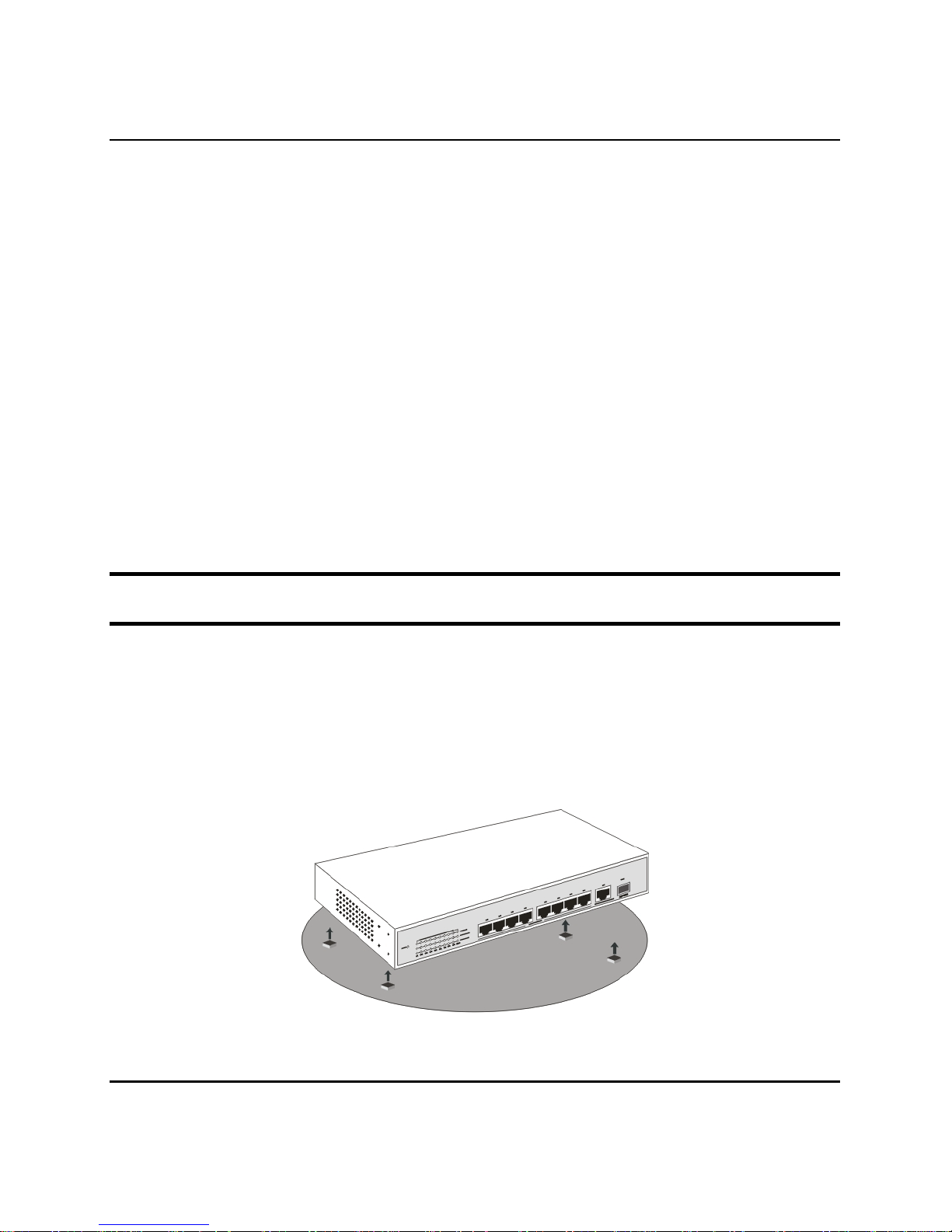
Installing the Switch on a Desktop
When installing the Switch on a desktop or shelf, the rubber feet
included with the Switch should first be attached. Attach these
cushioning feet on the bottom at each corner of the device. Allow
enough ventilation space between the Switch and any other objects in
the vicinity.
10
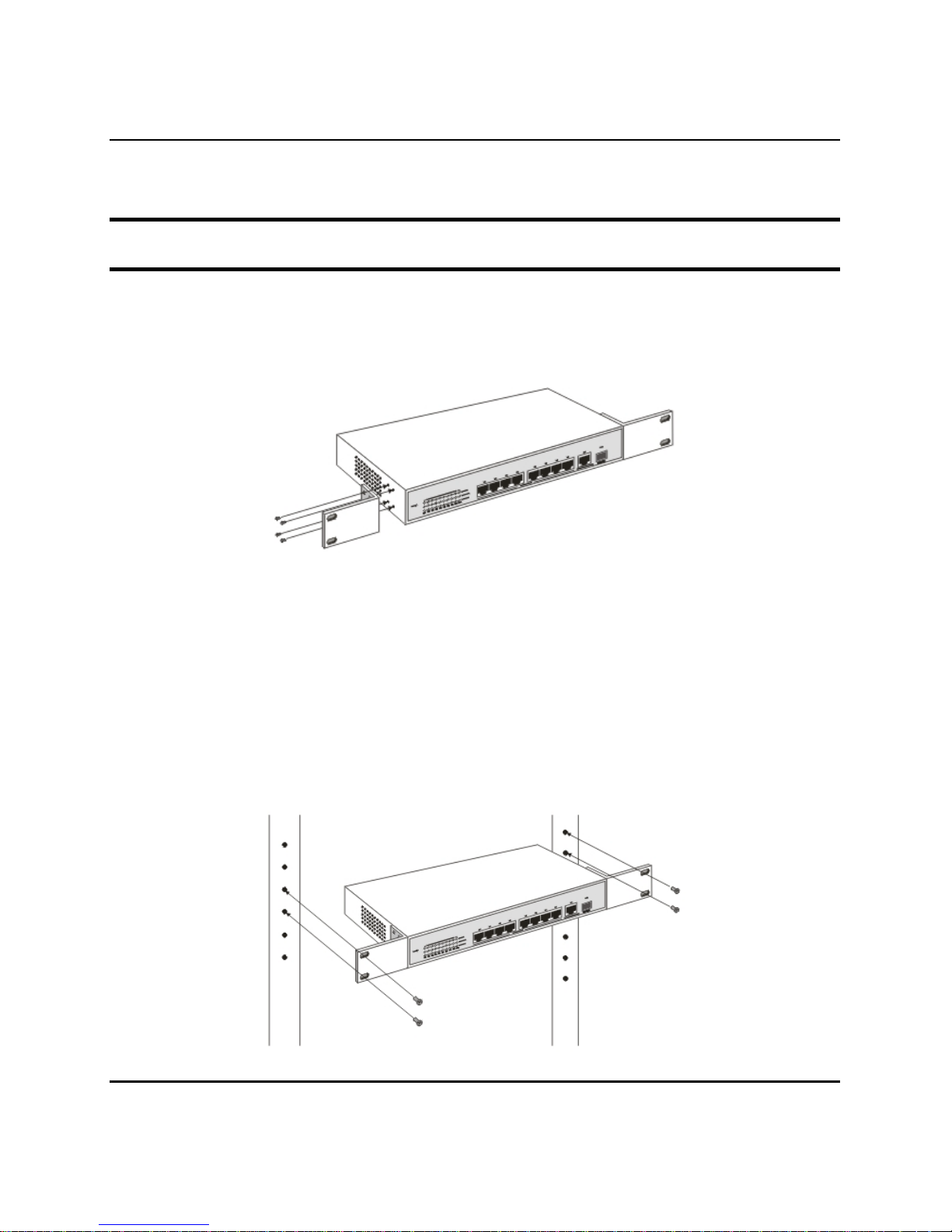
Figure 1. Installed on a Desktop
Installing the Switch on a Rack
The Switch can be mounted in a standard 19" rack. Use the following
diagrams to guide you.
Figure 2. Fasten mounting brackets to Switch
Fasten the mounting brackets to the Switch using the screws provided.
With the brackets attached securely, you can mount the Switch in a
standard rack as shown in Figure 2-2 on the following page.
Mounting the Switch in a Standard 19" Rack:
11

12
Figure 3. Installing Switch in a rack
Power on
The DES-2110 can be used with AC power sources 100 - 240 VAC,
50 - 60 Hz. The Switch’s power supply will adjust to the local power
source automatically.
Plug one end of the AC power cord into the power connector of the
Switch and the other end into the local power source outlet.
After the Switch is powered on, the LED indicators will momentarily
blink. This blinking of the LED indicators represents a reset of the
system
IDENTIFYING EXTERNAL COMPONENTS
This chapter describes the front panel, rear panel and LED indicators
of the Switch
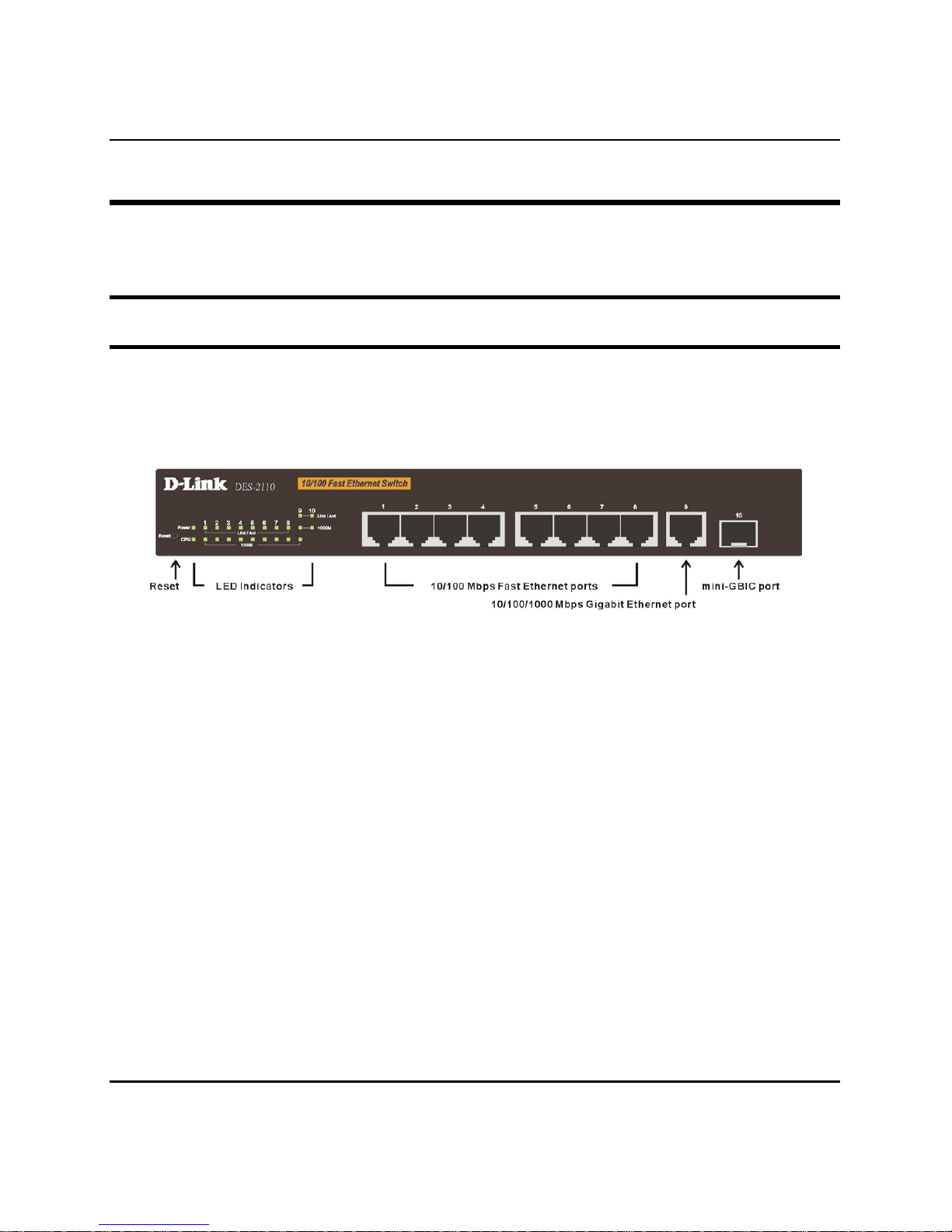
Front Panel Components
The front panel of the Switch consists of eight (8) 10/100Mbps Fast
Ethernet ports, one (1) 10/100/1000Mbps Gigabit Ethernet port, one
(1) mini-GBIC port, LED indicators and Reset button.
Figure 4. Front panel view
Port 1~8: Eight 10/100Mbps Fast Ethernet ports.
Port 9: One 10/100/1000Mbps Gigabit Ethernet ports (port 9).
Port 10: One mini-GBIC port (port 10)
LED Indicators: Comprehensive LED indicators that display the
conditions of the Switch and status of the network. A description of
these LED indicators follows (see LED Indicators).
Reset: The Reset button is to reset all the setting back to the factory
default.
Note: Be sure that you recorded the setting of your device, else all the setting will
be erased when pressing the “Reset” button.
13
Rear Panel
The rear panel of the Switch contains an AC power connector.
Figure 5. Rear panel view
The AC power connector is a standard three-pronged connector that
supports the power cord. Plug-in the female connector of the provided
power cord into this socket, and the male side of the cord into a power
outlet. The Switch automatically adjusts its power setting to any
supply voltage in the range from 100 ~ 240 VAC at 50 ~ 60 Hz.
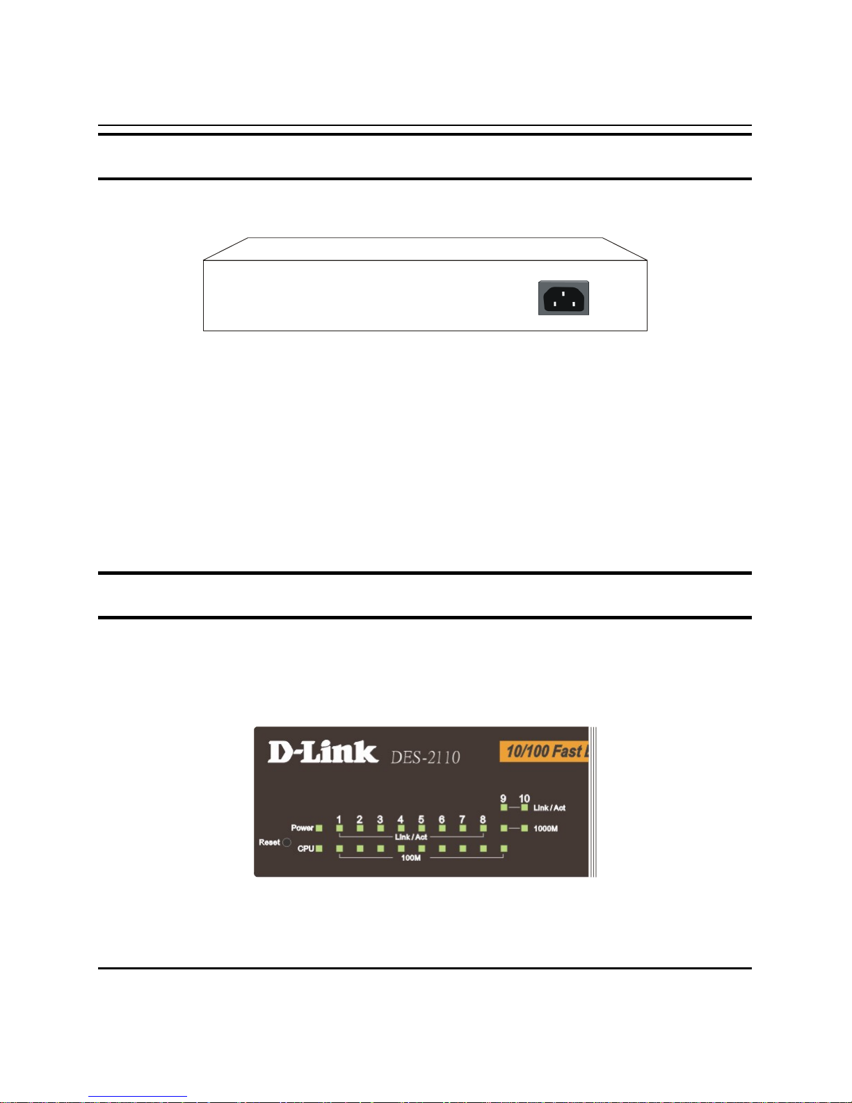
LED Indicators
The LED indicators of the Switch include Power, CPU and Port
Status LEDs. The following shows the LED indicators for the Switch
along with an explanation of each indicator.
Figure 6. LED indicators
14

15
Power and CPU LEDs
Power
On :
This LED will light green after the Switch is powered on to
indicate the ready state of the device.
Off :
When the switch powered off or the power cord has improper
connection.
CPU
Blinking :
When the CPU is working, the CPU LED is blinking.
On/Off :
The CPU is not working.
Ports 1~8, 10/100M Fast Ethernet Ports Status LEDs
Link/Act
On :
When the Link/Act LED lights on, the respective port is
successfully connected to an Ethernet network.
Blinking :
When the Link/Act LED is blinking, the port is transmitting or
receiving data on the Ethernet network.
Off :
No link.
100M
On :
When the 100Mbps LED lights on, the respective port is
connected to a 100Mbps Fast Ethernet network.
Off :
When the respective port is connected to a 10Mbps Ethernet
network

16
Port 9, Gigabit Ethernet Port Status LEDs
Link/Act
On :
When the Link/Act LED lights on, the respective port is
successfully connected to an Ethernet network.
Blinking :
When the Link/Act LED is blinking, the port is transmitting or
receiving data on the Ethernet network.
Off :
No link.
100M
On :
When the 100Mbps LED lights on, the respective port is
connected to a 100Mbps Fast Ethernet network.
Off :
When the respective port is connected to a 10Mbps Ethernet or
1000Mbps Gigabit Ethernet network.
1000M
On :
When the 100Mbps LED lights on, the respective port is
connected to a 100Mbps Fast Ethernet network.
Off :
When the respective port is connected to a 10Mbps Ethernet or
100Mbps Fast Ethernet network
Port 10, mini-GBIC Port Status LEDs
Link/Act
On
:
When the mini-GBIC module is installed and connected to a
network, the Link/Act LED lights on.
Blinking
:
When the LED is blinking, the mini-GBIC module is receiving data
on a network.
Off
:
No mini-GBIC module inserted or no link.
1000M
On :
When the 1000Mbps LED lights on, the respective port is
connected to a 1000Mbps Gigabit Ethernet network.
Off :
When the respective port is disconnected to the network

17
INTRODUCTION TO SWITCH MANAGEMENT
Management Options
Web Management Utility
Web-based Management Interface
Command Line Interface (CLI)
SNMP-Based Management Managing
Management Options
This system may be managed in-band using TCP/IP Telnet protocol
and web-based management, accessible through a web browser.
Web Management Utility
With the Web Management Utility, you can easily discover all the
Web Management Switch, assign the IP Address, changing the
password and upgrading the new firmware.
Web-based Management Interface
After you have successfully installed the Switch, you can configure
the Switch, display statistics using a web browser, such as Netscape
Navigator (version 6.2 and higher) or Microsoft® Internet Explorer
(version 5.0).

18
Command Line Interface (CLI)
The Switch supports a Command Line Interface (CLI) that allows the
user to connect to the Switch’s management agent using the TCP/IP
Telnet protocol.
SNMP-Based Management
You can manage the Switch with an SNMP-compatible console
program. The Switch supports SNMP version 1.0. The SNMP agent
decodes the incoming SNMP messages and responds to requests with
MIB objects stored in the database. The SNMP agent updates the MIB
objects to generate statistics and counters.

19
CONFIGURATION THE SWITCH
Through the Web Browser, Telnet and SNMP you can configure the
Switch such as Port setting, VLAN, QoS, SNMP, Spanning Tree…
etc.
Web Management Utility
With the attached Web Management Utility, you can easily discover
all the Web Management Switch, assign the IP Address, changing the
password and upgrading the new firmware.
Installing the Web Management Utility
The following gives instructions guiding you through the installations
of the Web Management utility.
1. Insert the Utility CD in the CD-Rom Drive.
2. From the Start menu on the Windows desktop, choose Run.
3. In the Run dialog box, type D:\Web Management
Utility\setup.exe (D:\ depends where your CD-Rom drive is
located) and click OK.
4. Follow the on-screen instructions to install the utility.
5. Upon completion, go to Program Files ->
web_management_utility and execute the Web Management
utility. (Figure 6.)
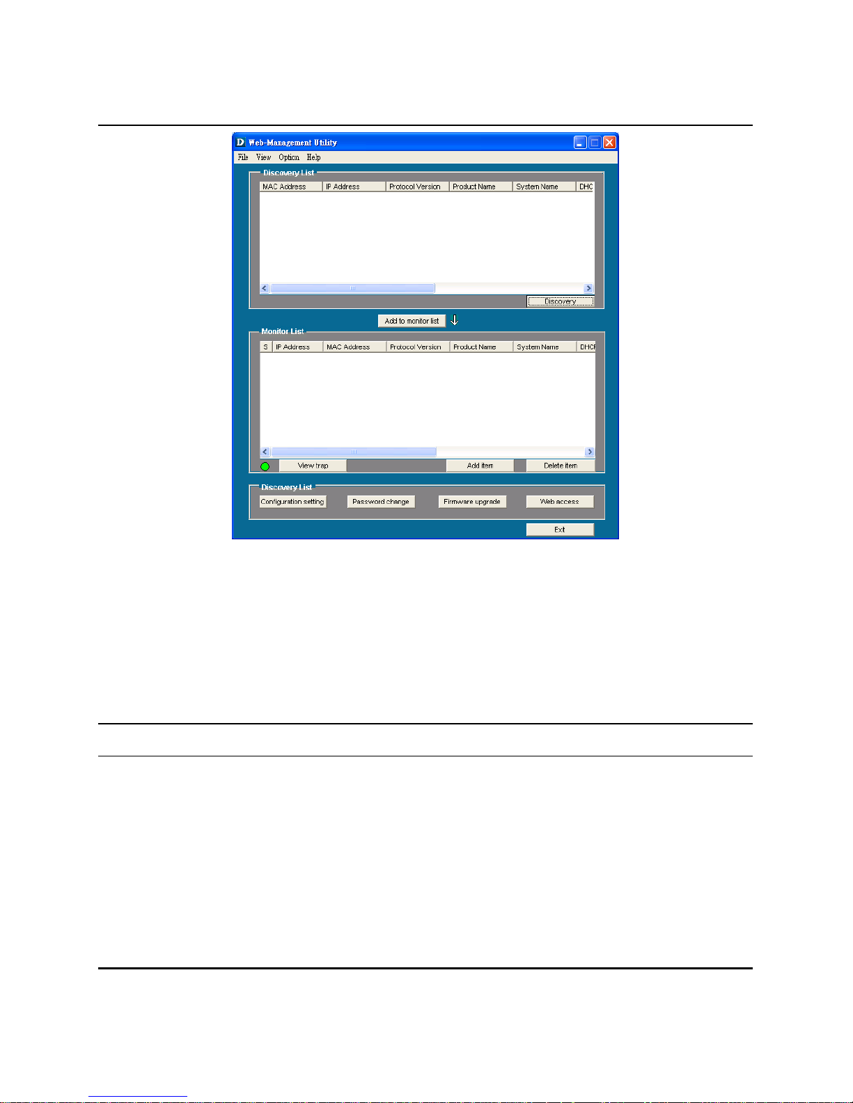
Figure 7. Web Management Utility
The Web Management Utility was divided into four parts, Discovery
List, Monitor List, Device Setting and Toolbar function, for details
instruction, follow the below section.
Discovery List
This is the list where you can discover all the Web management
devices in the entire network.
By pressing the “Discovery” button, you can list all the Web
Management devices in the discovery list.
Double click or press the “Add to monitor list” button to select a
device from the Discovery List to the Monitor List.
20

System word definitions in the Discovery List:
MAC Address: Shows the device MAC Address.
IP Address: Shows the current IP address of the device.
Protocol version: Shows the version of the Utility protocol.
Product Name: Shows the device product name.
System Name: Shows the appointed device system name.
Location: Shows where the device is located.
Trap IP: Shows the IP where the Trap to be sent.
Subnet Mask: Shows the Subnet Mask set of the device.
Gateway: Shows the Gateway set of the device.
Monitor List
All the Web Smart Device in the Monitor List can be monitored; you
can also receive the trap and show the status of the device.
System word definitions in the Monitor List:
S: Shows the system symbol of the Web-Smart device,
represent for device system is not alive.
IP Address: Shows the current IP address of the device.
MAC Address: Shows the device MAC Address.
Protocol version: Shows the version of the Utility protocol.
Product Name: Shows the device product name.
System Name: Shows the appointed device system name.
Location: Shows where the device is located.
Trap IP: Shows the IP where the Trap to be sent.
Subnet Mask: Shows the Subnet Mask set of the device.
Gateway: Shows the Gateway set of the device.
21
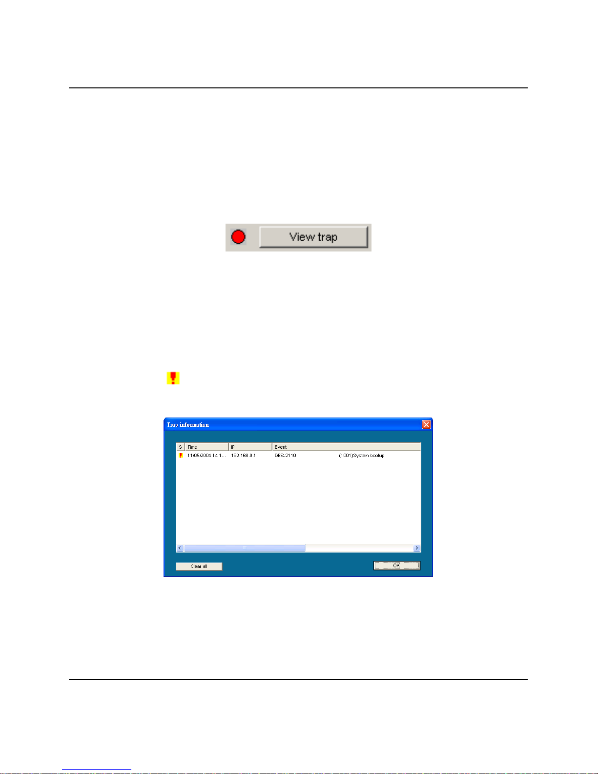
View Trap: The Trap function can receive the events that happen
from the Web Management Switch in the Monitor List.
There is a light indicator behind the “View Trap” button, when the
light indicates in green, it means that there is no trap transmitted, and
else when it indicates in red, it means that there is new trap
transmitted, this is to remind us to view the trap. (Figure 8.)
Figure 8.
When the “View Trap” button is clicked, a Trap Information window
will pop out, it will show the trap information including the Symbol,
Time, Device IP and the Event occurred. (Figure 9. Trap information)
The symbol “
” represents the trap signal arise, this symbol will
disappear after you review and click on the event record.
Figure 9. Trap information
22
 Loading...