

Page 1

1
Model No.: DCS-45
User’s Manual
Ⅰ. Introduction
The DCS-45 camera housing is built using die-cast aluminum, powder coated and stove
nished. The design and manufacture is adapted to the highest technical standard with IP
66 level of environmental protection. The housing is provided with an adjustable semi-cable-
managed mounting bracket.
(D)
(E)
(F)
(K)
(G)
Fig.1
(B)
90°90°
78
65
(H)
Fig.2
Inner space for camera mount
W90 x H70 x L230mm
1. Use the rear section of the mounting bracket (D)
as a template for marking the position of the
mounting holes (H). Remove and drill the holes
accordingly.
2. Attach the mounting bracket arm to the wall using
the rawlplugs and screws provided.
3. Attach the main housing enclosure (K) to the
mounting bracket with two of 1/4” x 14.7 mm
trilobular screws (F) provided.
4. Release screw (E) on the mounting bracket to pan
the housing and then release screw (G) to tilt the
housing. Position the housing as required for the
correct camera coverage and then securely tighten
the screws.
5. Feed cables through the cover plate (B) of the
mounting bracket from the wall, or by using cable
conduits.
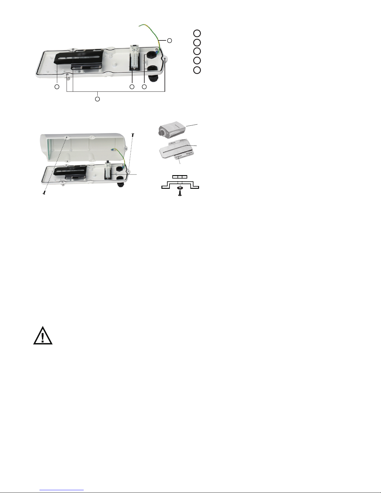
Ⅱ. Mounting conguration of DCS-45
Page 2
2
4
5
1 2 3
Ⅲ. Fitting instructions for camera
1 Camera mounting platform
2 Terminal block assembly
3 Cable conduits PGB13.5 x 2
4 Captive retainning 1/4” Screws x 3
5 Ground wire
Fig.3
(G)
(F)
(A)
(B)
(C)
(D)
(C)
(E)
(G)
(J)
(I)
(H)
1. Unscrew the 3 captive retaining screws (C) and remove the housing cover (A) from the
housing base (B).
2. Release the 4 keyhole screws (F) and then slide and withdraw the camera platform (G)
from the housing base (B).
3. Mount the camera (H) onto the camera platform (G) using the 1/4” UNC screw (I) supplied,
ensuring that the insulation pad (J) is mounted between the platform and the camera.
Always check if the camera is rmly attached to the platform.
4. Connect the camera power cable to the rear terminal block (E) through the rst
cable conduit (D).
5. Connect the video cable to the camera through the second cable conduit (D).
IMPORTANT NOTE:
ALWAYS UNPLUG THE TOP SECTION OF THE EARTH WIRE FROM THE BASE WIRE WHEN
DISASSEMBLING THE HOUSING. REMEMBER TO PLUG THE TOP AND BOTTOM TOGETHER
AGAIN WHEN REASSEMBLING THE HOUSING.
Page 3

3
Subject to the terms and conditions set forth herein, D-Link Systems, Inc. (“D-Link”) provides this Limited Warranty:
Only to the person or entity that originally purchased the product from D-Link or its authorized reseller or distributor, and
Only for products purchased and delivered within the fifty states of the United States, the District of Columbia, U.S. Possessions or
Protectorates, U.S. Military Installations, or addresses with an APO or FPO.
Limited Warranty: D-Link warrants that the hardware portion of the D-Link product described below (“Hardware”) will be free from
material defects in workmanship and materials under normal use from the date of original retail purchase of the product, for the period
set forth below (“Warranty Period”), except as otherwise stated herein.
Hardware: One (1) year
Hardware, including power supplies, fans, spare parts and spare kits: Ninety (90) days
The customer's sole and exclusive remedy and the entire liability of D-Link and its suppliers under this Limited Warranty will be, at
D-Link’s option, to repair or replace the defective Hardware during the Warranty Period at no charge to the original owner or to refund
the actual purchase price paid. Any repair or replacement will be rendered by D-Link at an Authorized D-Link Service Office. The
replacement hardware need not be new or have an identical make, model or part. D-Link may, at its option, replace the defective
Hardware or any part thereof with any reconditioned product that D-Link reasonably determines is substantially equivalent (or superior)
in all material respects to the defective Hardware. Repaired or replacement hardware will be warranted for the remainder of the
original Warranty Period or ninety (90) days, whichever is longer, and is subject to the same limitations and exclusions. If a material
defect is incapable of correction, or if D-Link determines that it is not practical to repair or replace the defective Hardware, the actual
price paid by the original purchaser for the defective Hardware will be refunded by D-Link upon return to D-Link of the defective
Hardware. All Hardware or part thereof that is replaced by D-Link, or for which the purchase price is refunded, shall become the
property of D-Link upon replacement or refund.
Limited Software Warranty: D-Link warrants that the software portion of the product (“Software”) will substantially conform to D-Link’s
then current functional specifications for the Software, as set forth in the applicable documentation, from the date of original retail
purchase of the Software for a period of ninety (90) days (“Software Warranty Period”), provided that the Software is properly installed
on approved hardware and operated as contemplated in its documentation. D-Link further warrants that, during the Software Warranty
Period, the magnetic media on which D-Link delivers the Software will be free of physical defects. The customer's sole and exclusive
remedy and the entire liability of D-Link and its suppliers under this Limited Warranty will be, at D-Link’s option, to replace the
non-conforming Software (or defective media) with software that substantially conforms to D-Link’s functional specifications for the
Software or to refund the portion of the actual purchase price paid that is attributable to the Software. Except as otherwise agreed by
D-Link in writing, the replacement Software is provided only to the original licensee, and is subject to the terms and conditions of the
license granted by D-Link for the Software. Replacement Software will be warranted for the remainder of the original Warranty Period
and is subject to the same limitations and exclusions. If a material non-conformance is incapable of correction, or if D-Link determines
in its sole discretion that it is not practical to replace the non-conforming Software, the price paid by the original licensee for the
non-conforming Software will be refunded by D-Link; provided that the non-conforming Software (and all copies thereof) is first returned
to D-Link. The license granted respecting any Software for which a refund is given automatically terminates.
Non-Applicability of Warranty: The Limited Warranty provided hereunder for Hardware and Software portions of D-Link's products
will not be applied to and does not cover any refurbished product and any product purchased through the inventory clearance or
liquidation sale or other sales in which D-Link, the sellers, or the liquidators expressly disclaim their warranty obligation pertaining to the
product and in that case, the product is being sold "As-Is" without any warranty whatsoever including, without limitation, the Limited
Warranty as described herein, notwithstanding anything stated herein to the contrary.
Submitting A Claim: The customer shall return the product to the original purchase point based on its return policy. In case the
return policy period has expired and the product is within warranty, the customer shall submit a claim to D-Link as outlined below:
The customer must submit with the product as part of the claim a written description of the Hardware defect or Software
nonconformance in sufficient detail to allow D-Link to confirm the same, along with proof of purchase of the product (such as a copy
of the dated purchase invoice for the product) if the product is not registered.
The customer must obtain a Case ID Number from D-Link Technical Support at 1-877-453-5465, who will attempt to assist the
customer in resolving any suspected defects with the product. If the product is considered defective, the customer must obtain a
Return Material Authorization (“RMA”) number by completing the RMA form and entering the assigned Case ID Number at
https://rma.dlink.com/
.
After an RMA number is issued, the defective product must be packaged securely in the original or other suitable shipping package
to ensure that it will not be damaged in transit, and the RMA number must be prominently marked on the outside of the package.
Do not include any manuals or accessories in the shipping package. D-Link will only replace the defective portion of the product
and will not ship back any accessories.
The customer is responsible for all in-bound shipping charges to D-Link. No Cash on Delivery (“COD”) is allowed. Products sent
COD will either be rejected by D-Link or become the property of D-Link. Products shall be fully insured by the customer and
shipped to D-Link Systems, Inc., 17595 Mt. Herrmann, Fountain Valley, CA 92708. D-Link will not be held responsible for any
packages that are lost in transit to D-Link. The repaired or replaced packages will be shipped to the customer via UPS Ground or
any common carrier selected by D-Link. Return shipping charges shall be prepaid by D-Link if you use an address in the United
States, otherwise we will ship the product to you freight collect. Expedited shipping is available upon request and provided shipping
charges are prepaid by the customer.
D-Link may reject or return any product that is not packaged and shipped in strict compliance with the foregoing requirements, or for
which an RMA number is not visible from the outside of the package. The product owner agrees to pay D-Link’s reasonable handling
and return shipping charges for any product that is not packaged and shipped in accordance with the foregoing requirements, or that is
determined by D-Link not to be defective or non-conforming.
What Is Not Covered: The Limited Warranty provided herein by D-Link does not cover: Products that, in D-Link’s judgment, have been
subjected to abuse, accident, alteration, modification, tampering, negligence, misuse, faulty installation, lack of reasonable care, repair
or service in any way that is not contemplated in the documentation for the product, or if the model or serial number has been altered,
tampered with, defaced or removed; Initial installation, installation and removal of the product for repair, and shipping costs; Operational
adjustments covered in the operating manual for the product, and normal maintenance; Damage that occurs in shipment, due to act of
God, failures due to power surge, and cosmetic damage; Any hardware, software, firmware or other products or services provided by
anyone other than D-Link; and Products that have been purchased from inventory clearance or liquidation sales or other sales in which
D-Link, the sellers, or the liquidators expressly disclaim their warranty obligation pertaining to the product. While necessary
maintenance or repairs on your Product can be performed by any company, we recommend that you use only an Authorized D-Link
Service Office. Improper or incorrectly performed maintenance or repair voids this Limited Warranty.
Disclaimer of Other Warranties: EXCEPT FOR THE LIMITED WARRANTY SPECIFIED HEREIN, THE PRODUCT IS PROVIDED
“AS-IS” WITHOUT ANY WARRANTY OF ANY KIND WHATSOEVER INCLUDING, WITHOUT LIMITATION, ANY WARRANTY OF
MERCHANTABILITY, FITNESS FOR A PARTICULAR PURPOSE AND NON-INFRINGEMENT. IF ANY IMPLIED WARRANTY CANNOT
BE DISCLAIMED IN ANY TERRITORY WHERE A PRODUCT IS SOLD, THE DURATION OF SUCH IMPLIED WARRANTY SHALL BE
Page 4

4
LIMITED TO THE DURATION OF THE APPLICABLE WARRANTY PERIOD SET FORTH ABOVE. EXCEPT AS EXPRESSLY
COVERED UNDER THE LIMITED WARRANTY PROVIDED HEREIN, THE ENTIRE RISK AS TO THE QUALITY, SELECTION AND
PERFORMANCE OF THE PRODUCT IS WITH THE PURCHASER OF THE PRODUCT.
Limitation of Liability: TO THE MAXIMUM EXTENT PERMITTED BY LAW, D-LINK IS NOT LIABLE UNDER ANY CONTRACT,
NEGLIGENCE, STRICT LIABILITY OR OTHER LEGAL OR EQUITABLE THEORY FOR ANY LOSS OF USE OF THE PRODUCT,
INCONVENIENCE OR DAMAGES OF ANY CHARACTER, WHETHER DIRECT, SPECIAL, INCIDENTAL OR CONSEQUENTIAL
(INCLUDING, BUT NOT LIMITED TO, DAMAGES FOR LOSS OF GOODWILL, LOSS OF REVENUE OR PROFIT, WORK STOPPAGE,
COMPUTER FAILURE OR MALFUNCTION, FAILURE OF OTHER EQUIPMENT OR COMPUTER PROGRAMS TO WHICH D-LINK’S
PRODUCT IS CONNECTED WITH, LOSS OF INFORMATION OR DATA CONTAINED IN, STORED ON, OR INTEGRATED WITH ANY
PRODUCT RETURNED TO D-LINK FOR WARRANTY SERVICE) RESULTING FROM THE USE OF THE PRODUCT, RELATING TO
WARRANTY SERVICE, OR ARISING OUT OF ANY BREACH OF THIS LIMITED WARRANTY, EVEN IF D-LINK HAS BEEN ADVISED
OF THE POSSIBILITY OF SUCH DAMAGES. THE SOLE REMEDY FOR A BREACH OF THE FOREGOING LIMITED WARRANTY IS
REPAIR, REPLACEMENT OR REFUND OF THE DEFECTIVE OR NON-CONFORMING PRODUCT. THE MAXIMUM LIABILITY OF
D-LINK UNDER THIS WARRANTY IS LIMITED TO THE PURCHASE PRICE OF THE PRODUCT COVERED BY THE WARRANTY.
THE FOREGOING EXPRESS WRITTEN WARRANTIES AND REMEDIES ARE EXCLUSIVE AND ARE IN LIEU OF ANY OTHER
WARRANTIES OR REMEDIES, EXPRESS, IMPLIED OR STATUTORY.
Governing Law: This Limited Warranty shall be governed by the laws of the State of California. Some states do not allow exclusion or
limitation of incidental or consequential damages, or limitations on how long an implied warranty lasts, so the foregoing limitations and
exclusions may not apply. This Limited Warranty provides specific legal rights and you may also have other rights which vary from state
to state.
Trademarks: D-Link is a registered trademark of D-Link Systems, Inc. Other trademarks or registered trademarks are the property of
their respective owners.
Copyright Statement: No part of this publication or documentation accompanying this product may be reproduced in any form or by
any means or used to make any derivative such as translation, transformation, or adaptation without permission from D-Link
Corporation/D-Link Systems, Inc., as stipulated by the United States Copyright Act of 1976 and any amendments thereto. Contents are
subject to change without prior notice. Copyright 2005 by D-Link Corporation/D-Link Systems, Inc. All rights reserved.
For detailed warranty information applicable to products purchased outside the United States, please contact the
corresponding local D-Link office.
Ver. 2.00(I)
2008/12/08
625008000G
 Loading...