

Page 1

Workshop Manual
competence level 2
D 2011 w
TD 2011 w, TCD 2011 w
t
o
n
is
men
u
This doc
D
r
t
s
i
al
co
s
i
t
n e
ni
io
ut
ib
wed with
lo
c
do
yright prote
p
e
th
i
ut our
o
e
nt
i
r
p
or a
r
i
r
p
ted
r e
g
.
lec
e
re
ic
n
tro
ment.
orm
f
0312 4176 en
.
This document is subject to changes which may become necessary in the course of further development of the engines. Reprinting and reproductions of any kind, even in part, require our
written permission.
Page 2

The engine company.
Regarding copyright questions and licensing agreements
please contact :
TE-FI, Mr. Sonntag
Tel.: + 49 (0) 221 822-3053
EMail: sonntag.j@deutz.com
DEUTZ AG
Sales & Service Information Systems
Ottostraße 1
D-51149 Köln (Cologne)
Phone.: +49 (0) 221-822-0
Fax: +49 (0) 221-822-3525
Internet: www.deutz.com
E-Mail: info@deutz.com
Printed in Germany
All rights reserved
1st Edition, 12/2008
Order No. 0312 4176 en
Page 3

DEUTZ engines Table of contents
1 Foreword
2 General
3 User notes
3.1 General
3.2 Specifications
3.3 Operating manual and workshop manual
3.4 Job cards
3.5 Explanation of symbols
4 Technical data
4.1 Testing and setting data
4.2 Tightening specifications
5 Job card overview
5.1 Sorted alphabetically
5.2 Sorted numerically
6Job cards
7Commercial tools
8 Special tools
© 06/2008 17761-001
1/2
Page 4

DEUTZ enginesTable of contents
© 06/2008 17761-001
2/2
Page 5

DEUTZ engines Foreword
1 Foreword
1
© 05/2005 17762-001
1/4
Page 6

DEUTZ enginesForeword
1
© 05/2005 17762-001
2/4
Page 7

DEUTZ engines Foreword
z Read and observe the information in this docu-
mentation. You will avoid accidents, retain the
manufacturer's warranty and possess a fully
functional and ready to operate engine.
z This engine is built exclusively for purpose ac-
cording to the scope of delivery - defined by the
equipment manufacturer (use for the intended
purpose). Any use above and beyond this is considered improper use. The manufacturer will not
be liable for damages resulting from this. The
user bears the sole risk.
z Use for the intended purpose also includes ob-
servance of the operating, maintena nce and repair instructions specified by the manufacturer.
The engine may only be used, maintained and
repaired by persons who are familiar with this
and are aware of the risks involved.
z Make sure that this documentation is available to
everyone involved in the operation, maintenance
and repair and that they have understood the
contents.
z Failure to observe this documentation may lead
to malfunctions and engine damage as well as injury to persons for which the manufacturer will
not accept any liability.
z Prerequisite for proper maintenance and repair is
the availability of all the necessary equipment,
conventional and special tools and their perfect
condition.
z Engine parts such as springs, clamps, elastic re-
taining rings etc. pose an increased risk of injury
when handled incorrectly.
z The pertinent rules for the prevention of acci-
dents and other generally recognised health and
safety regulations must be observed.
z Maximum economy, reliability and long life is only
guaranteed when using DEUTZ original parts.
z Repair of the engine must correspond to its use
for the intended purpose. Only parts released by
the manufacturer for the respective purpose may
be used for conversion work. Unauthorised modifications to the engine exclude manufacturer liability for resulting damages. Failure to observe
this will void the warranty!
z The engines made by DEUTZ are developed for
a wide range of applications. A wide range of variants ensures that the respective special requirements are met.
z The engine is equipped according to the installa-
tion case, i.e. not all the parts and components
described in this documentation are installed in
your engine necessarily.
z We have done our best to highlight the differenc-
es so that you can easily find the operating, maintenance and repair instructions relevant to your
engine.
We are at your service for any questions you may
have in this matter.
Your DEUTZ AG
1
© 05/2005 17762-001
3/4
Page 8

DEUTZ enginesForeword
1
© 05/2005 17762-001
4/4
Page 9

DEUTZ engines General
2 General
2
© 11/2005 17763-001
1/4
Page 10

DEUTZ enginesGeneral
2
© 11/2005 17763-001
2/4
Page 11

DEUTZ engines General
DEUTZ engines are the product of years of re-
search and development. The profound expertise
gained through this, in combination with high demands on quality, attests to the fact that our engines
possess all the qualities of long life, high reliability
and low fuel consumption. It goes without saying
that the high environmental protection requirements
are also met.
Maintenance and care are the only way the engine
can satisfy the demands you make on it. Compliance with the prescribed maintenance times and the
careful execution of maintenance and care work are
therefore essential. Difficult operating co nditio ns,
deviating from normal operation, must be particularly heeded.
Please consult one of our service representatives
responsible for operating faults and spare parts
questions. Our trained specialist personnel ensures
fast and professional repairs using original DEUTZ
spare parts in the event of damage.
Original spare parts from DEUTZ AG are always
manufactured according to the state of the art.
2
© 11/2005 17763-001
3/4
Page 12

DEUTZ enginesGeneral
2
© 11/2005 17763-001
4/4
Page 13

DEUTZ engines User notes
3 User notes
3
© 06/2008 17764-001
1/8
Page 14

DEUTZ enginesUser notes
3
© 06/2008 17764-001
2/8
Page 15

DEUTZ engines User notes
3.1 General
The documentation of the workshop manual has
been created based on the engine available at the
time of going to press.
There may be deviations in the descriptions, illustrations and parts due to further developments .
The maintenance work described in the operation
manual and in the workshop manual must be carried
out on schedule and completely. The maintenance
personnel must have the necessary technical
knowledge to perform the work. Safety and protection devices which are removed during mainten ance
work must be replaced again afterwards.
Caution!
The rules for the prevention of accidents and the
safety regulations must be observed during maintenance work.
Reference is made in the workshop manual job
cards to the regulations in chapter 3.2. These must
be read before working on the engine and must be
strictly followed.
The maintenance intervals and the work to be performed are specified in the maintenance schedule
of the operation manual. The job cards contain technical documentation on the execution of maintenance work.
3.2 Specifications
3.2.1 Accident prevention and safety regulations
The legally prescribed rules for the prevention of accidents must be observed. These are available from
professional associations or from dealers. These
are dependent on the application site, operating
mode and the operating and auxiliary materials being used.
Special protection measures are specified depending on the work being carried out, and are identified
in the job description.
Among other things it generally applies that:
z for the personnel:
– Only briefed personnel may operate or main-
tain the engine. Unauthorised persons are
prohibited access to the machine room.
– Wear close-fitting clothing and ear protectors
in the machine room when the engine is in operation.
– Only deploy trained personnel to do repairs
and maintenance work.
– Do not work on the fuel system when the en-
gine is running. The fuel system is under high
pressure - danger of death.
– Go to the workshop immediately in case of
leaks in the fuel system.
z for the engine room:
– Ensure adequate ventilation (do not cover air
shafts).
– Provide first aid kit and suitable fire extinguish-
ers. Check the filling and readiness for operation regularly.
– Only store inflammable materials in the ma-
chine room if they are essential for operation
of the system.
– Smoking and naked flames are prohibited in
the machine room.
z for operation, maintenance and repairs on the
engine:
– Wait 30 seconds after switching off the engine
before working on the fuel sytem.
– After all work on the fuel system, it must be
bleeded - see the operation manual, chapter
"6 Fuel system“.
– Only start the engine when all the protective
devices have been fitted. Make sure no-one is
standing in the danger area.
– Cleaning, maintenance and repair work may
only be performed with the engine at a standstill and secured against starting.
– Injection lines and high pressure pipes must
not be deformed.
3
© 06/2008 17764-001
3/8
Page 16

DEUTZ enginesUser notes
– Damaged injection lines and high-pressure
pipes must be renewed.
– Injection lines and high pressure fuel lines
must never be connected when the engine is
running.
– Do not place hands near to a leak in the high
3
pressure fuel system.
– Also carefully check all high pressure compo-
nents visually before performing tests on the
running engine. Wear suitable protective
clothing (for example protective glasses).
Leaks are a potential source of danger for
workshop personnel.
– Even if no leaks are discernible on the high
pressure fuel system, the workshop personnel
should avoid the immediate danger zone or
wear suitable protective clothing (such as protective glasses) when performing tests on the
running engine and during the first trial run.
– Always stay out of range of a fuel jet, as it
could cause severe injury.
– Smoking is strictly prohibited when working on
the fuel system.
– Do not work near to sparks and flames.
– Never disconnect an injector when the engine
is running.
3.2.2 Cleanliness instructions and measures for handling the DEUTZ Common Rail System
The DEUTZ Common Rail system used in the
DEUTZ engines consists of high-precision components which are exposed to extreme stress . Grea t
attention must be paid to cleanliness when working
on the fuel system due to the high precision technology.
Notes and measures to be observed before
starting work on the fuel system
z The fuel system must be closed. Make a visual
inspection for leaks / damage to the fuel system.
z Clean the whole engine and engine room with the
system closed before starting work on the fuel
system.
z The engine must be dry when you start working
on the fuel system.
z Blowing (dry) with compressed air is only permis-
sible with the fuel system closed.
z When using a steam jet, first cover up the control
unit, the cable plugs, all other electrical plug connections and the generator. Also, the steam jet
may not be pointed directly at them.
z Electrical plug connections must be plugged
when spraying.
z Remove loose parts (for example paint chips
from assembly work) with an industrial vacuum
cleaner or other suction device. Only suction may
be used in assembly work on the open fuel system.
z Only work on the fuel system in a clean environ-
ment (no dust, no grinding or welding). Avoid
draughts (dust). Clean the workshop floor regularly. No brake or performance test benches may
be kept or operated in the same room.
z Air currents which kick up dust, such as those
caused by brake repairs or the starting of engines, should be avoided.
z For work such as removal and installation on de-
fective hydraulic components on the Common
Rail System it is recommended to partition off a
separate workshop area in the factory. This must
be separate from other areas in which general
vehicle repairs such as brake repairs are carried
out.
z No general machine tools may be operated in
this room.
z Regular cleaning of the workshop area is manda-
tory. Draughts, ventilation systems and heating
fans should be minimised.
z Areas of the engine room from which particles of
dirt could be loosened (for example the bottom
part of the tipped driver cab) must be covered
with fresh clean film.
z Working materials and tools must be cleaned be-
fore work. Only use tools without damage to the
chrome plating or tools which are not chromeplated.
Notes and measures to be observed during work
on the fuel system or with the fuel s ystem ope n.
z Only work in clean overalls.
z Only lint-free cleaning cloths may be used for
work on the fuel system.
z Remove loose parts (for example paint chips
from assembly work) with an industrial vacuum
cleaner or other suction device. Only suction may
be used in assembly work on the open fuel system.
z Working materials and tools must be cleaned be-
fore work. Only use tools without damage to the
chrome plating or tools which are not chromeplated.
z Do not use used cleaning fluid or test fluid for
cleaning.
z Compressed air must not be used for cleaning on
the open fuel system.
z Work on removed components may only be per-
formed at a suitably equipped workbench.
© 06/2008 17764-001
4/8
Page 17

DEUTZ engines User notes
z When removing and installing components, no
materials which can leave behind particles or fibres (cardboard, wood, cloths) may be used.
z Removed parts may only be rubbed down with
clean, lint-free cloths. No dirt particles may be
rubbed into the components.
z Openings on the components and on the engine
must be closed immediately with suitable stoppers/caps.
z The stoppers/caps may only be removed imme-
diately before installing.
z Store stoppers/caps free from dust and dirt in the
original packaging and dispose of after using
once.
z Only remove new parts from the original packag-
ing just before installation.
z Removed components must be kept in new, seal-
able bags or - if available - in the packaging of the
new parts.
z Always use the original packaging of the new part
to send back the removed components.
Notes and measures for the vehicle workshop
area
z For work such as removal and instal la tion on de-
fective hydraulic components on the Common
Rail System it is recommended to partition off a
separate workshop area in the factory. This must
be separate from other areas in which gener al
vehicle repairs such as brake repairs are carried
out.
z The workshop floor is sealed or tiled.
z No welding gear, grinders, general machine
tools, brakes or performance test benc he s ma y
be operated in this room.
z Regular cleaning of the workshop area is manda-
tory. Draughts, ventilation systems and heating
fans should be minimised.
Notes and measures for workbench and tools in
the vehicle hall
operating materials among other things. The renewed parts / operating materials must be stored,
transported and disposed of according to regulations. The owner himself is responsible for this.
Disposal includes recycling and the scrapping of
parts / operating materials, although recycling has
priority.
Details of disposal and their monitoring are governed by regional, national and international laws
and directives which the system operator mu st ob serve on his own responsibility.
3
z A special workbench must be set up for work on
removed components.
z Clean the removal and installation tools regularly
and keep them in a closed tool cabinet.
z Remove loose parts (for example paint chips
from assembly work) with an industrial vacuum
cleaner or other suction device.
z Working materials and tools must be cleaned be-
fore work. Only use tools without damage to the
chrome plating or tools which are not chr o me plated.
3.2.3 Disposal regulations
The work described in the operation manual and
workshop manual necessitates renewal of parts and
© 06/2008 17764-001
5/8
Page 18

DEUTZ enginesUser notes
3.3 Operation manual and workshop
manual
To structure the information to suit the user, the
service documentation is divided into operation
manual and workshop manual.
3
The operation manual contains a general description and instructions for all other maintenance wo rk.
It contains the following chapters:
1. Contents, General
2. Engine description
3. Operation
4. Operating media
5. Maintenance
6. Care and maintenance work
7. Faults, causes and remed ies
8. Engine conservation
9. Technical data
10.Service
The workshop manual assumes knowledge of the
contents of the operation manual. This applies especially for the safety regulations. The workshop
manual describes repairs to the engine and components for which more effort and appropriately qualified technicians are required.
3.4 Job cards
The job cards are divided in the workshop manual
into "W" and "I" job cards.
The "W" job card documents standard repairs on the
engine and/or its components. The necessary tools
and special tools are also specified in the "W" job
card.
The "I" job card additionally documents the appropriate work procedures for repairing the engine and /
or its components. The workshop must satisfy special conditions to perform these work procedures.
Special tools and machine tools must be available,
for example.
3.4.1 Numbering of job cards
The job card numbers follow the pattern W 02-04-
01. The individual parts of this pattern are explained
below:
z W 02-04-01: Documentation type
– WWorkshop manual
– I......Repair instructions
z W 02-04-01: Maintenance group
– 00...General / interdisciplinary activities
– 01...Cylinder head
– 02Drive system
– 03...Crankcase
– 04...Engine control system
– 05...Speed governing
– 06...Exhaust system / Charging
– 07...Fuel system
– 08...Lube oil system
– 09...Cooling system
– 10...Compressed air system
– 11...Monitoring system
– 12...Other components
– 13...Electrical system
z W 02-04-01: Component grouping
z W 02-04-01: Consecutive number
© 06/2008 17764-001
6/8
Page 19
DEUTZ engines User notes
Triebwerk
W 02-04-01
6
16
12
4
6
1 2 3
8
10
11
575
9
13
14
15
8
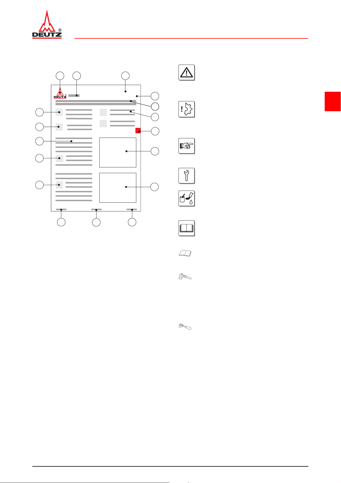
3.4.2 Structure of a job card
1. DEUTZ AG,
publisher of service documentation
2. Engine type (e.g. TCD 2013 4V)
3. Maintenance group
4. Job card number or topic
5. Title of job card
6. Reference to other job cards
7. Chapter
8. Graphic or photo
9. DEUTZ internal creation number
10.Page number
11.Date of issue of job card
12.Note
13.Danger / Important
14.Work sequence
15.Special tools; auxiliary materials
16.Conventional tools
3.5 Explanation of symbols
Danger!
of death or to health. Must be observed!
For example: The incorrect use or conversion of the turbocharger can lead to serious
injury.
Caution!
Danger to the component/engine. Noncompliance can lead to destruction of the
component/engine.
Must be observed!
Note
General notes on assembly, environmental
protection etc. No potential danger for man
or machine.
Tool
Conventional and special tools required for
the work.
Auxiliary materials
Working materials required in addition to
the tools for performing the work
(e.g. greases, oils, adhesives, sealants)
References
to important documents or job cards for the
work process.
For example: Job card W 04-05-05
Reference
to a document or a job card within the work
process.
Test and setting data
The necessary values are specified here.
If several values are necessary, a cross reference is given to the Test and Setting Values table.
For example:
ID no. P01 61 = valve clearance, inlet
Tightening specification
The necessary values are specified here.
If several values are necessary, a cross reference is given to the Tightening Specifications table.
For example:
ID no. A01 001 = cylinder head screws
3
© 06/2008 17764-001
7/8
Page 20

DEUTZ enginesUser notes
3
© 06/2008 17764-001
8/8
Page 21

D 2011 w Technical data
TD 2011 w, TCD 2011 w Testing and setting data
4 Technical data
4.1 Testing and setting data
4
© 12/2008 19484-001
1/6
Page 22
D 2011 wTechnical data
+0.27
+0.27
+0.01
−0.01
+50
−50
+20
−20
TD 2011 w, TCD 2011 wTesting and setting data
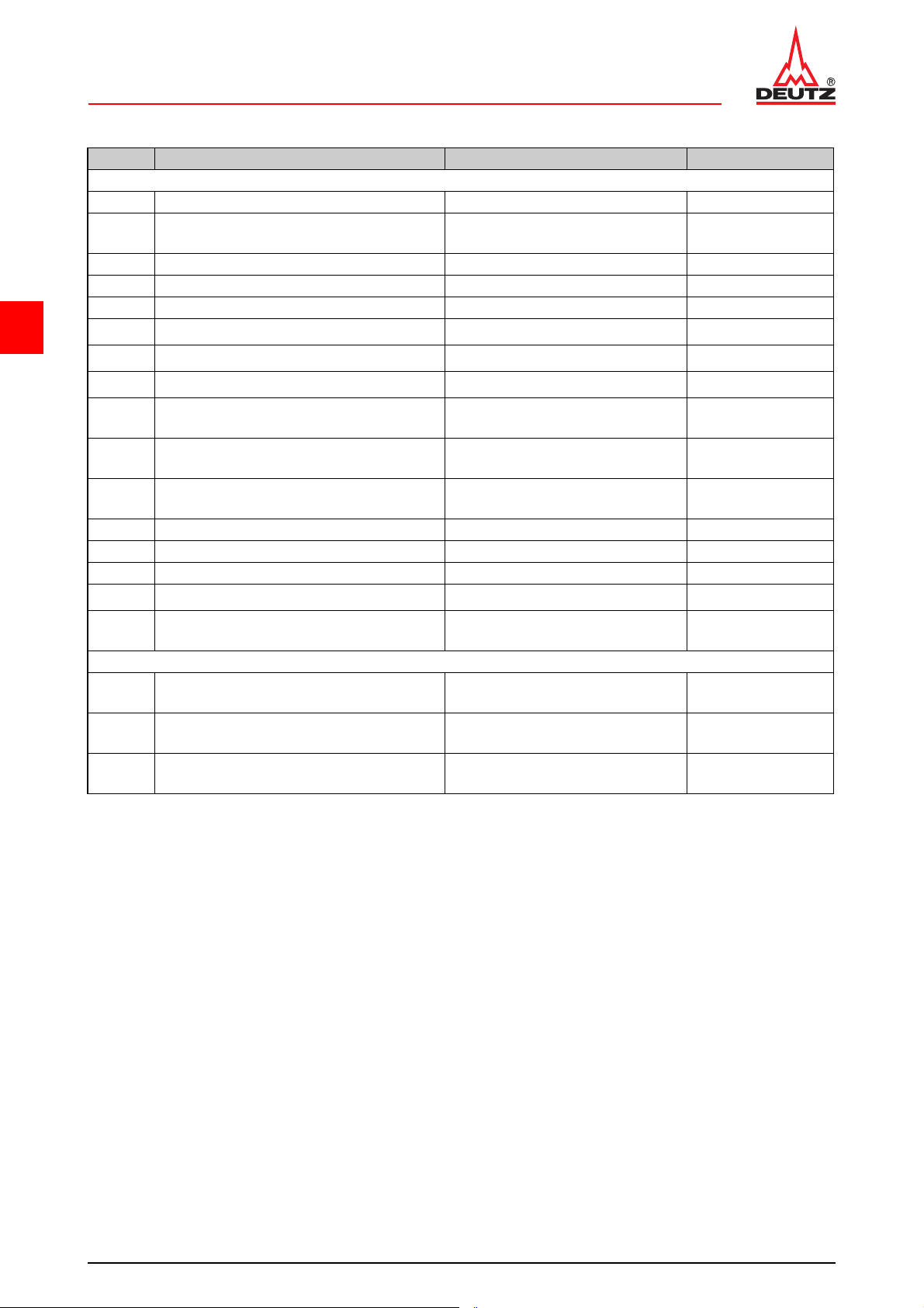
ID no. Name Additional information Value
D 2011 w / TD 2011 w / TCD 2011 w
P00 04 Engine weight according to DIN 70020-A approx. 268 kg
P00 51 Compression pressure
P00 71 Ignition sequence 1-3-4-2
P01 61 Valve clearance (inlet) 0.3 mm
P01 62 Valve clearance (outlet) 0.5 mm
4
P01 72 Rocker arm, bore, diameter (outlet)
P01 73 Rocker arm, bore, diameter (inlet)
P01 74 Rocker arm pin, diameter
P02 75 Piston overhang
P02 76 Piston overhang
P02 77 Piston overhang
Identification, cylinder head gasket = 1 recess
Identification, cylinder head gasket = 2 recesses
Identification, cylinder head gas-
ket = 3 recesses
P08 74 Thermostat, compression spring, length 45.7 mm
P09 11 Thermostat, start of opening 86 - 90 °C
P09 13 Thermostat, stroke distance at least 9 mm
P12 11 V-bel t tension, individual V-belts AVX 10 First assembly
P12 21 V-belt tension, individual V-belts AVX 10
Check after 15 minutes running
under load
D 2011 w / TD 2011 w / TCD 2011 w Recess cylinder head
P02 75 Piston overhang
P02 76 Piston overhang
P02 77 Piston overhang
Identification, cylinder head gas-
ket = 1 recess
Identification, cylinder head gas-
ket = 2 recesses
Identification, cylinder head gas-
ket = 3 recesses
25 - 30 bar
(2500 - 3000 kPa)
18 mm
18 mm
17,97 mm
0.325 - 0.604 mm
0.605 - 0.704 mm
0.705 - 0.804 mm
450 N
300 N
9.820 - 10.140 mm
10.141 - 10.239 mm
10.240 - 10.310 mm
© 12/2008 19484-001
2/6
Page 23

D 2011 w Technical data
TD 2011 w, TCD 2011 w Tightening specifications
4.2 Tightening specifications
4
© 12/2008 19484-001
3/6
Page 24
D 2011 wTechnical data
TD 2011 w, TCD 2011 wTightening specifications
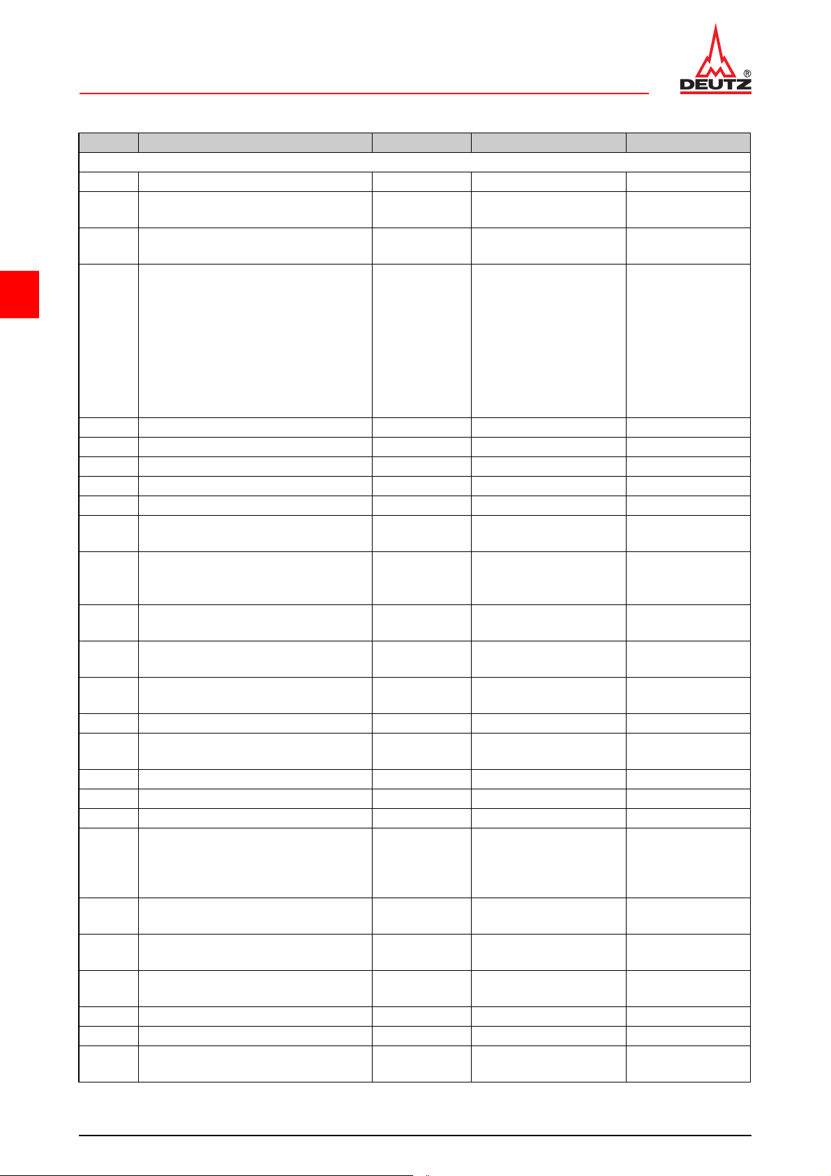
ID no. Name Screw type Notes / Remark Value
D 2011 w / TD 2011 w / TCD 2011 w
A00 001 Clam pin g bracke t on cran kc as e 90 Nm
A00 002
A00 003
4
A01 001 Cylinder head on crankcase
A01 001 Cylinder head on crankcase Stage 2 80 Nm
A01 001 Cylinder head on crankcase Stage 3 160 Nm
A01 001 Cylinder head on crankcase Stage 4 90°
A01 002 Rocker arm bracket on cylinder head 21 Nm
A01 003 Lockin g nut, va lve adju ste r 20 Nm
A01 004
A03 060
A05 041
A05 065
A06 001 Exhaust pipe at cylinder head
A07 001 Fuel injector on cylinder head 21 Nm
A07 003
A07 015 Fuel supply line to injection pump Hollow screw Replace sealing rings 29 Nm
A07 024 Fuel supply pump on crankcase 21 Nm
A07 061 Fuel return line on injection pump Hollow screw Replace sealing rings 29 Nm
A08 003 Oil filter console on crankcase
A08 048
A08 051
A08 072
A08 091 Oil pressure switch on crankcase M10x1 13 Nm
A09 001 Thermostat housing to crankcase M8x100-10.9 34 Nm
A09 002
Clamping bracket on adapter for
assembly block
Mounting foot/engine mounting on
crankcase
Cylinder head cover on cylinder
head
Crankcase bleeding on front cover /
on cylinder head cover / on cylinder
head
Lifting magnet (engine shutdown) on
front cover
Lifting magnet (start amoun t release)
on front cover
Injection line on fuel injector / injection pump
Control line to oil filter console /
crankcase
Lubricating oil cooler on oil filter console
Thermostat on crankcase, locking
screw,
Outlet nozzles on thermostat housing
90 Nm
M14x55-12.9
M14x100-12.9
Stage 1:
Cylinder head screws
can be used a maximum of 3x with written
documentation.
Otherwise use new
cylinder head screws.
Observe tightening
sequence.
Torx screw,
coated
M12x1.5 25 Nm
Torx
M8x50-8.8
Torx
M8x90-8.8
Hollow screw
M10x1
M6x16-10.9 13 Nm
M8x30-10.9 22 Nm
Use new screws. 55 Nm
200 Nm
30 Nm
8.5 Nm
8.5 Nm
8.5 Nm
10 Nm
21 Nm
18 Nm
90 Nm
© 12/2008 19484-001
4/6
Page 25
D 2011 w Technical data
TD 2011 w, TCD 2011 w Tightening specifications
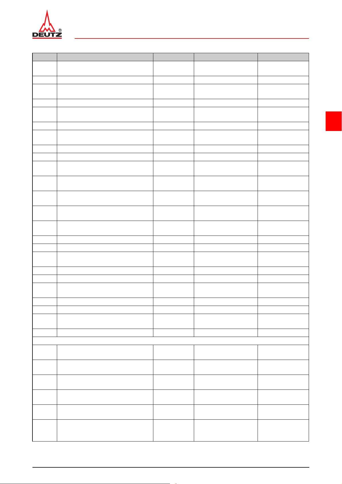
ID no. Name Screw type Notes / Remark Value
A09 010 Coolant pump on thermostat housing
A09 020 Pipe clip on holder M6x16 21 Nm
A09 031
A09 042 Ventilator on flange hub M8x40-10.9 30 Nm
A09 045 Air bearing on console M10x110-12.9
A09 045 Air bearing on console M10x110-12.9 Stage 2: 120°
A12 001 Flywheel on cra nk sha ft
A12 001 Flywheel on crankshaft Stage 2: 60°
A12 001 Flywheel on crankshaft Stage 3: 30°
A12 031
A12 041
A12 051
A12 052
A12 056
A13 001 Starter on crankcase 43.5 Nm
A13 009 Shield on crankcase M6x14-8.8 8.5 Nm
A13 012 Generator on console
A13 015 Clamping bracket on generator M8x30-8.8 22 Nm
A13 016 Clamping bracket on console M8x35-8.8 22 Nm
A13 031
A13 032 Heating plug on cylinder head 21 Nm
A13 034 Cable co nn ec tio n to glo w plu g 4 Nm
A13 081
A13 082 Cable G1.D+ to generator M5 3.5 Nm
D2011w
A06 030
A06 057
A06 062
A06 063
A06 071
A06 072
Temperature transmitter on thermostat housing
V belt pulley/flange hub on output
flange
V-belt tensioning pulley (holder) on
front cover
Hydraulic pump on hydraulic pump
console
Tensioning pulley on hydr au lic pump
console
Protective hood on hydraulic pump
console
Glow plug in charge air line / intake
pipe
Charging current cable to generator
B+
Air suction intake pipe on cylinder
head
Pipe to exhaust gas return valve/
cylinder head (cooling - intake)
Exhaust return pipe to exhaust return
valve
Exhaust gas collection pipe to
exhaust gas return valve
Pipe to crankcase (exhaust gas
return - cooling - return)
Pipe to exhaust gas return valve
(exhaust gas return - cooling -
return)
M8x35-10.9
M8x100-10.9
Stage 1:
Use new screw.
Stage 1:
Use new screws
M10x30-8.8 43 Nm
M8x70-10.9
M8x75-10.9
Torx screw,
coated
Hollow screw
M12x1.5
M8x65-10.9 20 Nm
Hollow screw
M8x1
Hollow screw
M12x1.5
Use new screws. 21 Nm
20 Nm
25 Nm
30 Nm
30 Nm
45 Nm
57 Nm
21 Nm
8.5 Nm
34 Nm
60 Nm
6.5 Nm
29 Nm
20 Nm
12 Nm
29 Nm
4
© 12/2008 19484-001
5/6
Page 26
D 2011 wTechnical data
TD 2011 w, TCD 2011 wTightening specifications
ID no. Name Screw type Notes / Remark Value
Torx
M10x25-10.9
A06 073
A06 074
Exhaust gas collection pipe (exhaust
gas return) on cylinder head
Exhaust gas return pipe to cylinder
head (exhaust gas return)
4
A06 075
A07 087 Fuel filter console to crankcase 21 Nm
TD2011w / TCD2011w
A06 004 Pin bolts on exhaust pipe coated Use new pin bolts 12 Nm
A06 020 Turbocharger on exhaust pipe M8 21 Nm
A06 030 Charge air pipe on cylinder head
A06 094 Lifting magnet on fuel filter console Renew O-ring 10 Nm
A07 096
A08 042
A08 044
A08 049 Holder oil return line on crankcase
Safety cover on sensor housing
(exhaust gas return)
Cap on charge air-dependent full
load stop
Lubricating oil pipe on turbocharger /
crankcase
Oil return line, hex spuds to turbocharger
Torx
M10x30-10.9
Torx
M10x45-10.9
Locking screw
Torx-Plus
30IPR
Torx screw,
coated
Hollow screw Replace sealing rings 29 Nm
M16x1.5 Use new sealing ring 40 Nm
Torx,
M6x14-8.8
Use new screws. 55 Nm
8.5 Nm
8Nm
Use new screws. 21 Nm
8Nm
8.5 Nm
For the tightening procedure according to torque using a torque wrench, a maximum variation of the
tightening torque of +/- 10% is permissible.
© 12/2008 19484-001
6/6
Page 27

D 2011 w
TD 2011 w, TCD 2011 w Job card overview
5 Job card overview
5.1 Sorted alphabetically
5
© 12/2008 19488-001
1/12
Page 28

D 2011 wJob card overview
TD 2011w, TCD 2011 wSorted alphabetically
5
© 12/2008 19488-001
2/12
Page 29
D 2011 w Job card overview
TD 2011w, TCD 2011 w Sorted alphabetically
Activity Job card Maintenance group
Checking piston overhang W 01-04-09 Cylinder head
Checking the compression pressure W 00-02-06 General
Checking the thermostat (in the removed state) W 09-08-01 Cooling system
Disassembling, assembling and checking the rocker
arm and rocker arm
bracket
W 01-02-06 Cylinder head
Installing and removing charge air pressure-dependent full load stop
Mounting engine on assembly block and demounting
Removing and install the charge air line W 06-02-03 Exhaust system/Charging
Removing and installing cylinder head W 01-04-04 Cylinder head
Removing and installing fuel pipes W 07-10-06 Fuel system
Removing and installing temperature transmitter W 09-12-01 Cooling system
Removing and installing the control line W 08-16-01 Lube oil system
Removing and installing the coolant pump W 09-07-08 Cooling system
Removing and installing the crankcase bleeding W 03-01-11 Crankcase
Removing and installing the exhaust gas collection
pipe (Exhaust gas recirculation)
Removing and installing the exhaust gas return pipe W 06-09-07 Exhaust system/Charging
Removing and installing the exhaust gas return val-
ve
Removing and installing the exhaust line W 06-01-05 Exhaust system/Charging
W 07-10-08 Fuel system
W 00-05-01 General
W 06-09-08 Exhaust system/Charging
W 06-09-06 Exhaust system/Charging
5
Removing and installing the flywheel W 12-06-01 Other components
Removing and installing the fuel filter console W 07-10-08 Fuel system
Removing and installing the fuel injectors W 07-07-01 Fuel system
Removing and installing the fuel supply pump W 07-11-01 Fuel system
Removing and installing the generator W 13-02-03 Electrical system
Removing and installing the glow plug W 13-06-02 Electrical system
Removing and installing the heating plugs W 13-06-01 Electrical system
Removing and installing the hydraulic pump W 12-08-02 Other components
Removing and installing the intake manifold W 06-07-03
Removing
air pressure-dependent full load stop)
Removing and installing the lifting magnet (Engine
shutdown)
Removing and installing the lifting magnet (Start
amount release)
Removing and installing the lubricating oil cooler W 08-08-02 Lube oil system
and installing the lifting magnet (charge
W 07-10-08 Fuel system
W 11-00-03 Monitoring system
W 07-02-07 Fuel system
Exhaust system/Charging
© 12/2008 19488-001
3/12
Page 30

D 2011 wJob card overview
TD 2011w, TCD 2011 wSorted alphabetically
Activity Job card Maintenance group
Removing and installing the oil filter console W 08-11-07 Lube oil system
Removing and installing the oil pressure switch W 08 -11-08 Lube oil system
Removing and installing the rocker arm and rocker
arm bracket
Removing and installing the starter W 13-03-02 Electrical system
Removing and installing the thermostat W 09-08-02 Cooling system
Removing and installing the thermostat (Lubricating
5
oil cooler)
Removing and installing the thermostat housing W 09-08-04 Cooling system
Removing and installing the turbocharger W 06-06-04 Exhaust system/Charging
Removing and installing the V-belt pulley W 12-01-04 Other components
Renew V-belts, check V-belt tension W 12-02-01 Other components
Renewing the injection lines W 07-03-01 Fuel system
Setting valve clearance W 01-01-01 Cylinder head
W 01-02-02 Cylinder head
W 08-11-12 Lube oil system
© 12/2008 19488-001
4/12
Page 31

D 2011 w Job card overview
TD 2011 w, TCD 2011 w Sorted numerically
5.2 Sorted numerically
5
© 12/2008 19488-001
5/12
Page 32

D 2011 wJob card overview
TD 2011 w, TCD 2011 wSorted numerically
5
© 12/2008 19488-001
6/12
Page 33
D 2011 w Job card overview
TD 2011 w, TCD 2011 w Sorted numerically
Job card Activity Maintenance group
W 00-02-06 Checking the compression pressure General
W 00-05-01
W 01-01-01 Setting valve clearance Cylinder head
W 01-02-02
W 01-02-06
W 01-04-04 Removing and installing cylinder head Cylinder head
W 01-04-09 Checking piston overhang Cylinder head
W 03-01-11 Removing and installing the crankcase bleeding Crankcase
W 06-01-05 Removing and installing the exhaust line Exhaust system/Charging
W 06-02-03 Removing and install the charge air line Exhaust system/Charging
W 06-06-04 Removing and installing the turbocharger Exhaust system/Charging
W 06-07-03 Removing and installing the intake manifold Exhaust system/Charging
W 06-09-06
W 06-09-07 Removing and installing the exhaust gas return pipe Exhaust system/Charging
Mounting engine on assembly block and demounting
Removing and installing the rocker arm and rocker
arm bracket
Disassembling, assembling and checking the rocker
arm and rocker arm
bracket
Removing and installing the exhaust gas return valve
General
Cylinder head
Cylinder head
Exhaust system/Charging
5
W 06-09-08
W 07-02-07
W 07-03-01 Renewing the injection lines Fuel system
W 07-07-01 Removing and installing the fuel injectors Fuel system
W 07-10-06 Removing and installing fuel pipes Fuel system
W 07-10-08
W 07-10-08
W 07-10-08 Removing and installing the fuel filter console Fuel system
W 07-11-01 Removing and installing the fuel supply pump Fuel system
W 08-08-02 Removing and installing the lubricating oil cooler Lube oil system
W 08-11-07 Removing and installing the oil filter console Lube oil system
W 08-11-08 Removing and installing the oil pressure switch Lube oil system
W 08-11-12
Removing and installing the exhaust gas collection
pipe (Exhaust gas recirculation)
Removing and installing the lifting magnet (Start
amount release)
Removing and installing the lifting magnet (charge
air pressure-dependent full load stop)
Installing and removing charge air pressure-dependent full load stop
Removing and installing the thermostat (Lubricating
oil cooler)
Exhaust system/Charging
Fuel system
Fuel system
Fuel system
be oil system
Lu
W 08-16-01 Removing and installing the control line Lube oil system
W 09-07-08 Removing and installing the coolant pump Cooling system
© 12/2008 19488-001
7/12
Page 34
D 2011 wJob card overview
TD 2011 w, TCD 2011 wSorted numerically
Job card Activity Maintenance group
W 09-08-01 Checking the thermostat (in the removed state) Cooling system
W 09-08-02 Removing and installing the thermostat Cooling system
W 09-08-04 Removing and installing the thermostat housing Cooling system
W 09-12-01 Removing and installing temperature transmitter Cooling system
W 11-00-03
W 12-01-04 Removing and installing the V-belt pulley Other components
5
W 12-02-01 Renew V-belts, check V-belt tension Other components
W 12-06-01 Removing and installing the flywheel Other components
W 12-08-02 Removing and installing the hydraulic pump Other components
W 13-02-03 Removing and installing the generator Electrical system
W 13-03-02 Removing and installing the starter Electrical system
W 13-06-01 Removing and installing the heating plugs Electrical system
W 13-06-02 Removing and installing the glow plug Electrical system
Removing and installing the lifting magnet (Engine
shutdown)
Monitoring system
© 12/2008 19488-001
8/12
Page 35

DEUTZ engines Job cards
6Job cards
6
© 11/2005 17767-001
1/2
Page 36

DEUTZ enginesJob cards
6
© 11/2005 17767-001
2/2
Page 37
D 2011 w General
© 47534-0
TD 2011 w, TCD 2011 w W 00-02-06
Checking the compression pressure
Commercial available tools:
– Compression pressure
tester. . . . . . . . . . . . . . . . . . . . . . . . 8005
Special tools:
– Connector. . . . . . . . . . . . . . . . . . 100120
– W 01-01-01
– W 07-07-01
Attention!
Pay attention to utmost cleanliness when
working on the fuel system.
Remove residue paint and particles of dirt
before removing.
Clean the respective affected parts carefully. Blow damp areas dry with compressed air.
Observe the safety regulations and natio nal specifications for handling fuels.
Close all connections immediately after
opening with new, clean plugs/caps.
Do not remove plugs/caps until immediately before assembling.
Collect leaking operating substances in
suitable vessels and dispose of according
to regulations.
After all work on the fuel system, it must be
bleeded - see the operation manual, chapter "6 Fuel system“.
6
Checking the compression pressure
z Set valve clearance.
W 01-01-01
z Removing fuel injectors.
W 07-07-01
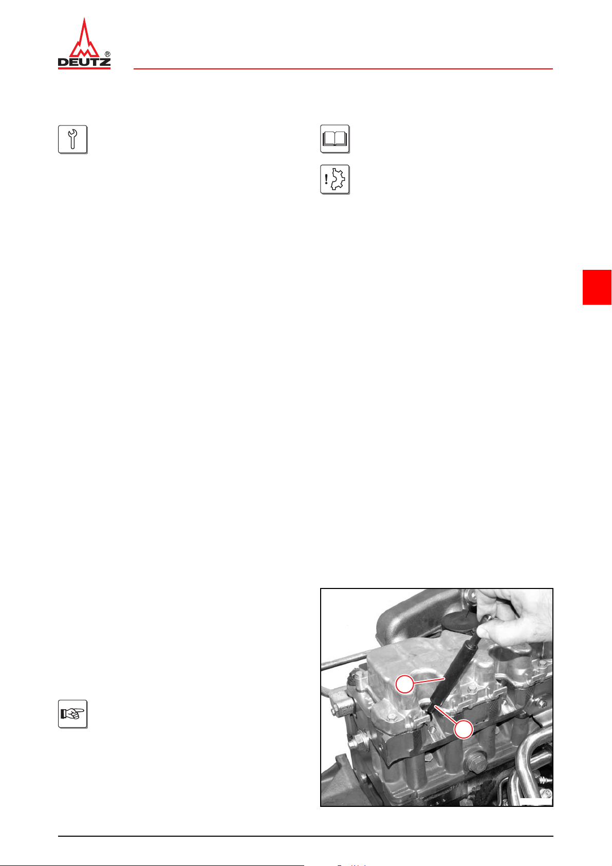
z Mount sealing ring (1).
Use sealing ring (1) for fuel injector.
z Insert connector (2).
© 12/2008 17768-001
1/6
2
1
Page 38
D 2011 wGeneral
© 47535-0
1
© 47536-0
© 46308-0
TD 2011 w, TCD 2011 wW 00-02-06
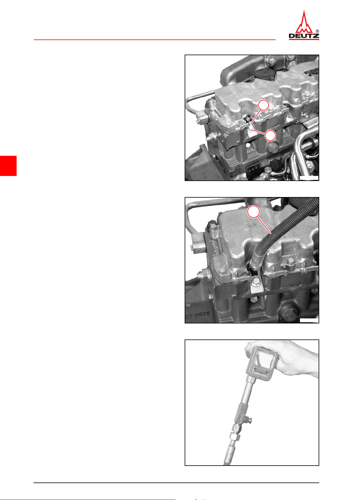
z Mount clamping shoe (1).
z Tighten screw (2).
21 Nm
1
2
6
z Connect adapter (1) to connector.
z Mount the compression tester on the adapter.
z Turn over engine with starter.
25-30bar (2500-3000kPa)
© 12/2008 17768-001
2/6
Page 39
D 2011 w General
© 45103-0
© 47537-0
© 47536-0
TD 2011 w, TCD 2011 w W 00-02-06
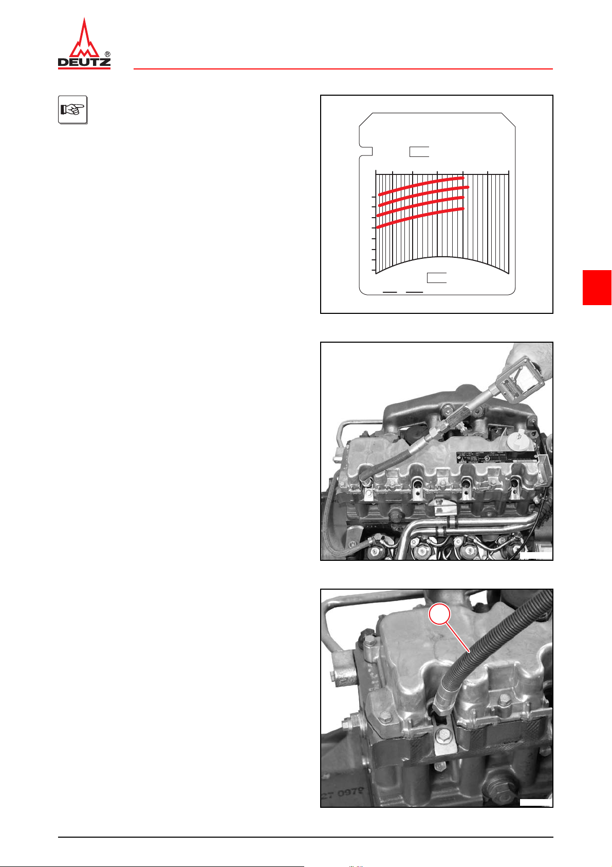
The measured compression pressure
depends on the starting speed during the
measuring process and the altitude of the
engine installation site. Therefore, limit
values cannot be determined exactly. The
compression pressure measurement is
only recommended as a reference measurement of all cylinders of an engine to each
other. If mor e than 15% deviation has been
determined, the cause should be determined by disassembling the cylinder unit concerned.
No.
Kompression in bar
Compression value in bar
Pression en bar
10
15
20
25
Zyl.
1
2
3
4
5
6
7
8
M
DBGM
OTOMETER
Made in Germany
Dat. _________
30
35
40
6
z Remove the compression pressure tester.
z Remove the compression pressure tester and
adapter (1).
1
© 12/2008 17768-001
3/6
Page 40
D 2011 wGeneral
© 47535-1
1
© 47534-1
TD 2011 w, TCD 2011 wW 00-02-06
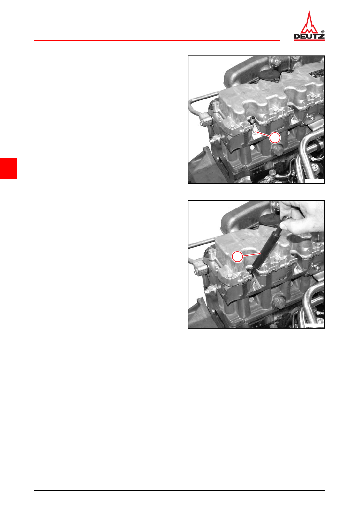
z Unscrew screw (1).
1
6
z Remove connector (1).
z Remove sealing ring.
z Install fuel injectors.
W 07-07-01
© 12/2008 17768-001
4/6
Page 41
D 2011 w General
TD 2011 w, TCD 2011 w W 00-02-06
Technical Data
Testing and setting data
ID no. Name Additional information Value
P00 51 Compression pressure
Tightening specifications
ID no. Name Screw type Notes / Remark Value
A07 001 Fuel injector on cylinder head 21 Nm
For the tightening procedure according to torque using a torque wrench, a maximum variation of the
tightening torque of +/- 10% is permissible.
25 - 30 bar
(2500 - 3000 kPa)
6
© 12/2008 17768-001
5/6
Page 42

D 2011 wGeneral
TD 2011 w, TCD 2011 wW 00-02-06
6
© 12/2008 17768-001
6/6
Page 43
D 2011 w General
1
1
© 47538-0
© 47539-0
TD 2011w, TCD 2011 w W 00-05-01
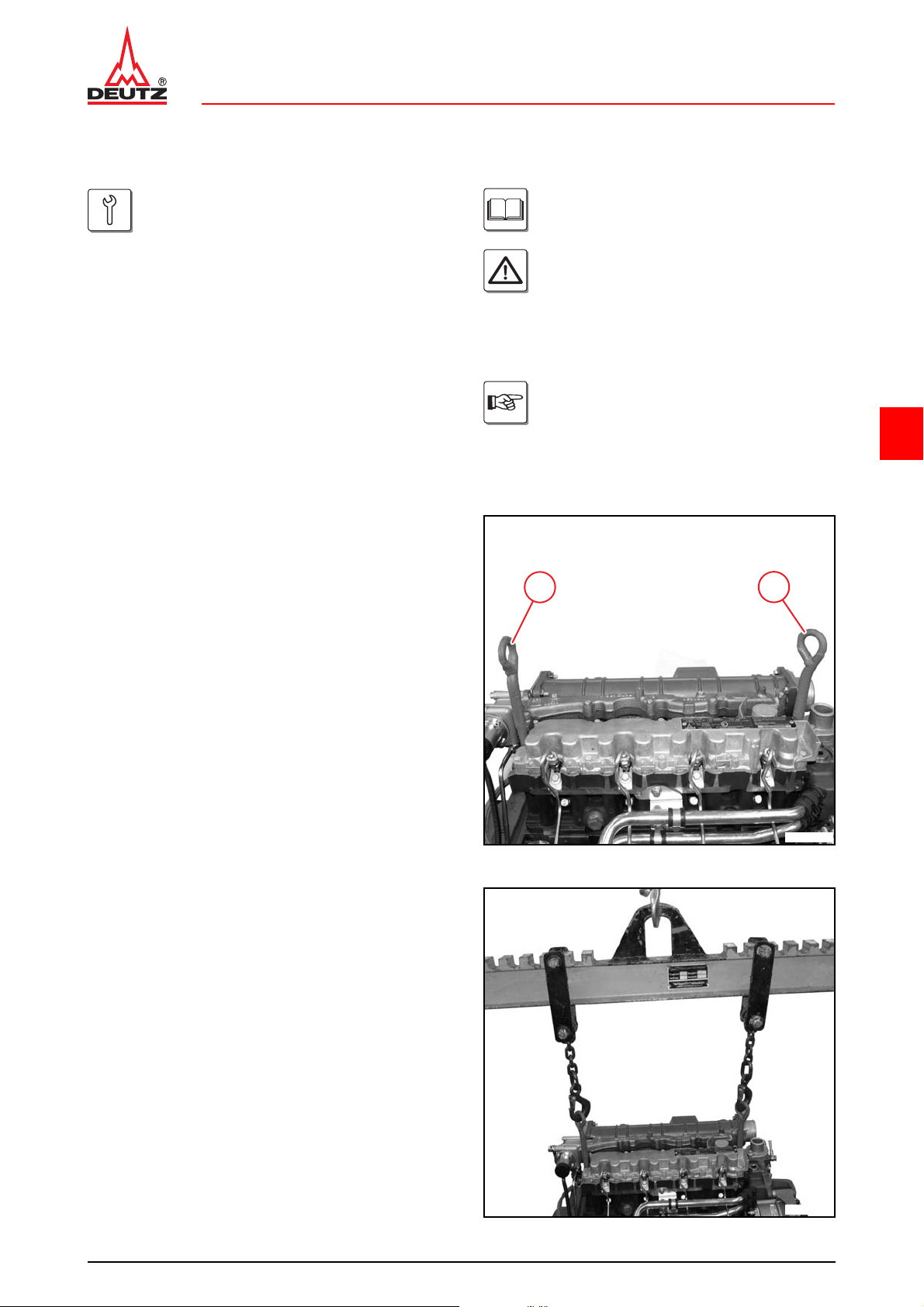
Mounting engine on assembly block and demounting
Commercial available tools:
– Lifting gear
– Suspension ropes
– Eyelet bolts
Special tools:
– Assembly block. . . . . . . . . . . . . . . . 6067
– Supporting bracket . . . . . . . . . .6067/114
– Clamping bracket . . . . . . . . . . .6067/115
Mounting engine on assembly block
z Remove starter.
W 13-03-02
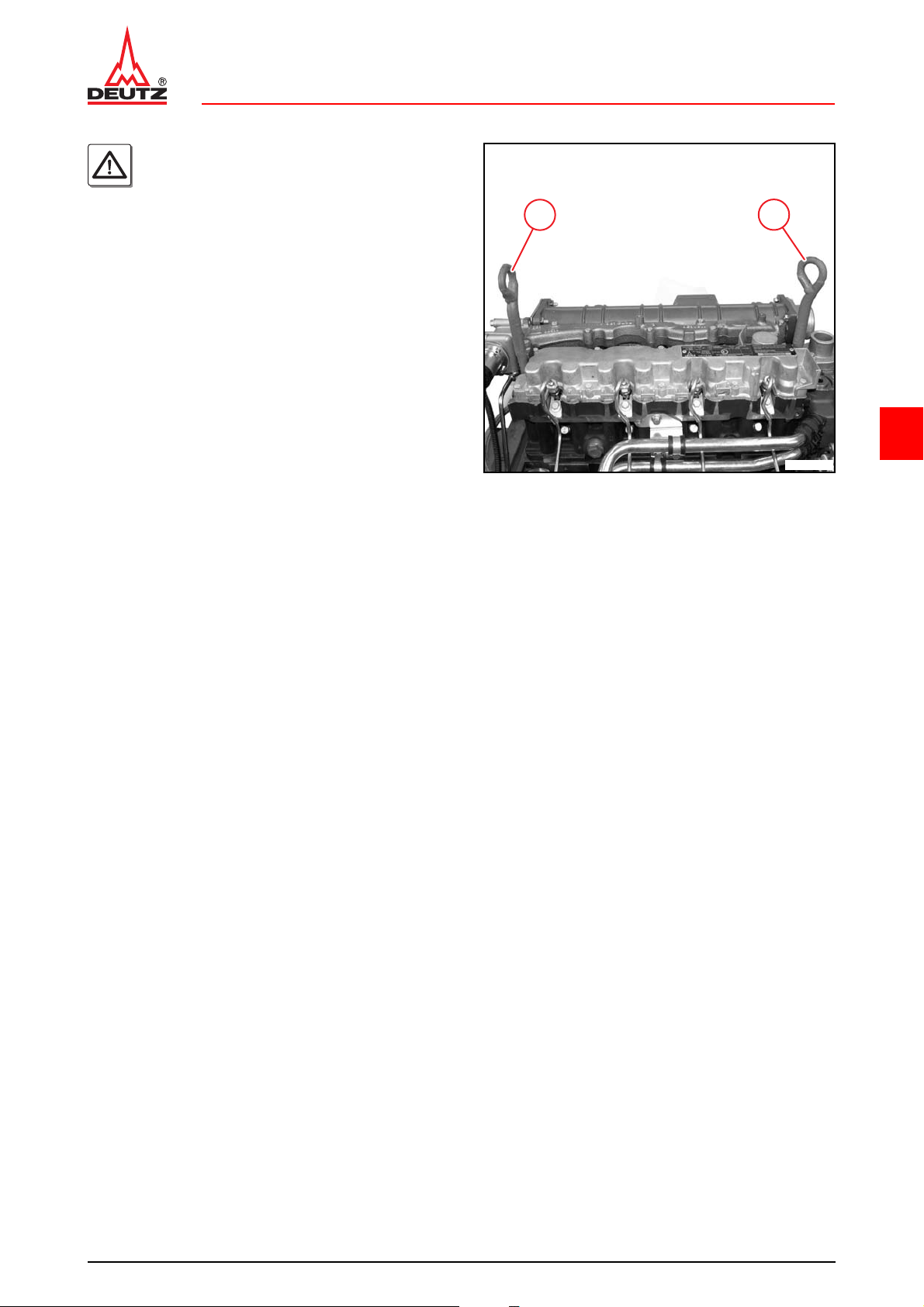
z Screw in eyelet bolts (1).
– W 13-03-02
Danger!
When using hoists (workshop crane) the
safety regulations for handling hoists must
be observed.
It is not permitted to stay under moving
loads.
Different customer scopes are not taken
into account in the repair sequence shown
here, accessories which deviate from the
standard equipment are not shown.
6
z Hang engine on workshop crane.
approx. 268 kg
© 12/2008 17769-001
1/6
Page 44
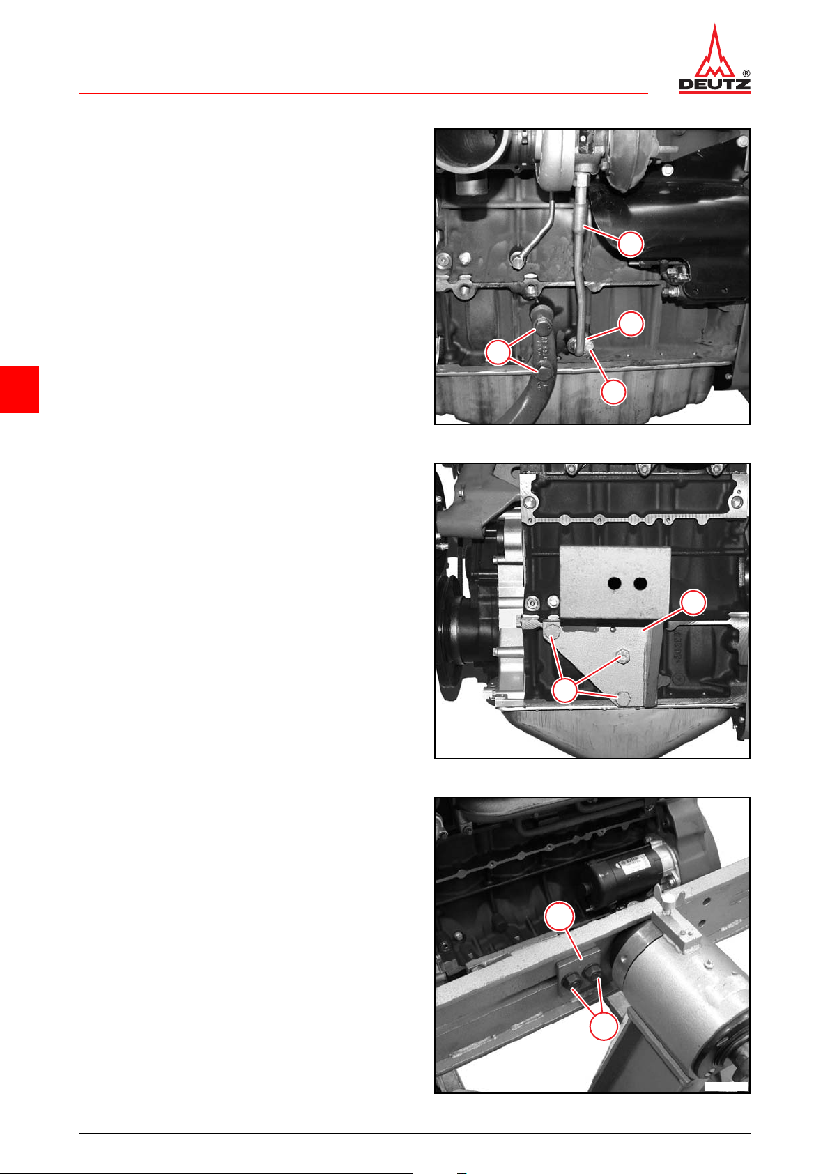
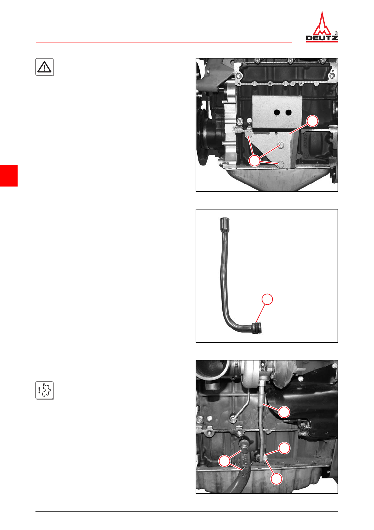
z Unscrew screws (1).
© 47532-3
© 47009-0
© 47577-0
z Remove all mounting feet.
– TD 2011 w, TCD 2011 w
z Unscrew screw (2).
z Remove holder (3).
z Remove oil return pipe (4).
D 2011 wGeneral
TD 2011w, TCD 2011 wW 00-05-01
4
3
1
6
2
z Mount clamping holder (1).
z Tighten screws (2).
90 Nm
1
2
z Align engine on engine block.
z Mount retainer plate (1).
z Tighten screws (2) and lock nuts.
90 Nm
1
2
© 12/2008 17769-001
2/6
Page 45
D 2011 w General
© 47538-0
1
1
© 47538-0
© 47577-0
TD 2011w, TCD 2011 w W 00-05-01
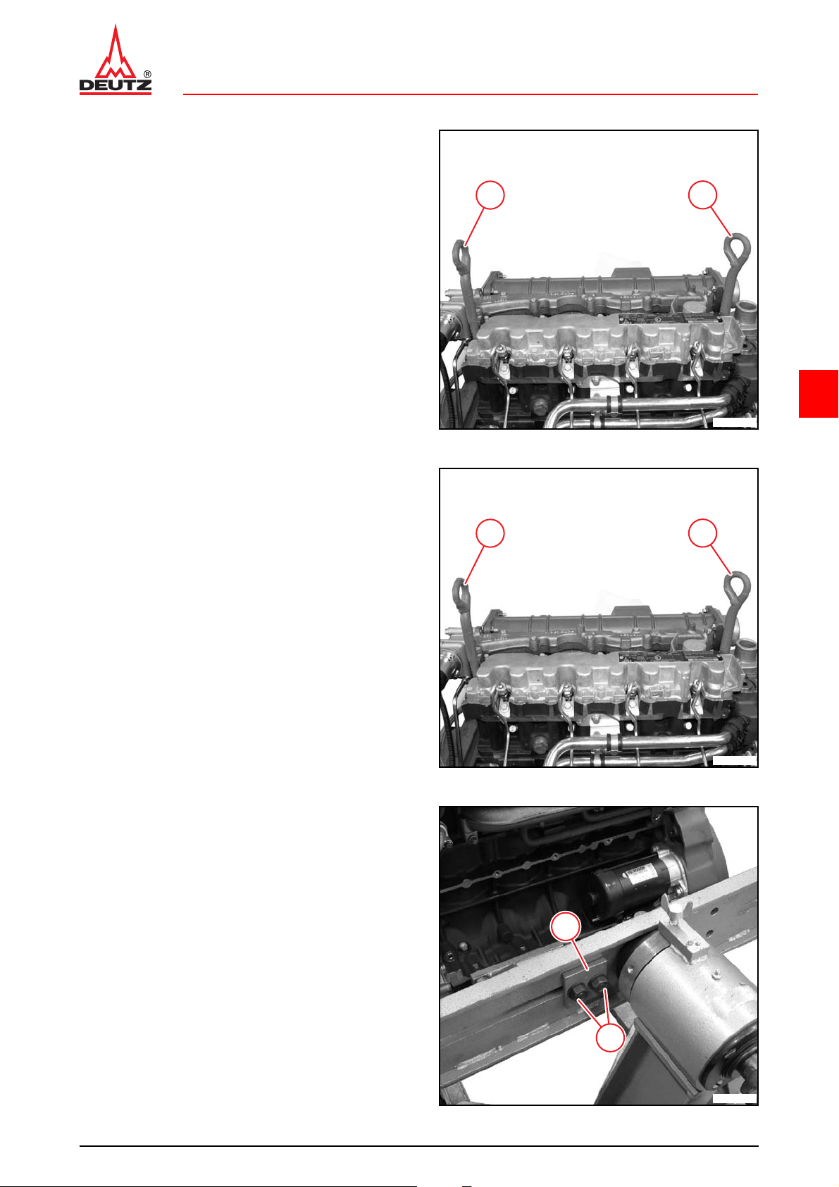
z Unhook the engine from the workshop crane.
z Unscrew eyelet bolts (1).
Demounting engine from assembly block
z Screw in eyelet bolts (1).
z Hang engine on workshop crane.
approx. 268 kg
1
1
6
z Loosen lock nuts.
z Unscrew screws (2).
z Remove retainer plate (1).
1
2
© 12/2008 17769-001
3/6
Page 46
D 2011 wGeneral
© 47009-0
© 39378-2
© 47532-4
TD 2011w, TCD 2011 wW 00-05-01
Danger!
Lower engine with workshop crane.
z Unscrew screws (2).
z Remove clamping bracket (1).
1
2
6
– TD 2011 w, TCD 2011 w
z Insert new O-ring (1).
z Lightly oil new O-ring (1).
– TD 2011 w, TCD 2011 w
z Mount oil return pipe (1).
Attention!
Install tension-free.
1
z Mount holder (2).
z Tighten screw (3).
8.5 Nm
– D 2011 w, TD 2011 w, TCD 2011 w
z Install all mounting feet.
z Tighten screws (4).
200 Nm
© 12/2008 17769-001
4/6
4
1
2
3
Page 47
D 2011 w General
© 47538-0
TD 2011w, TCD 2011 w W 00-05-01
Danger!
Put the engine down on a secure surface.
z Unhook the engine from the workshop crane.
z Unscrew eyelet bolts (1).
z Install starter.
W 13-03-02
1
1
6
© 12/2008 17769-001
5/6
Page 48
D 2011 wGeneral
TD 2011w, TCD 2011 wW 00-05-01
Technical Data
Testing and setting data
ID no. Name Additional information Value
P00 04 Engine weight according to DIN 70020-A approx. 268 kg
Tightening specifications
ID no. Name Screw type Notes / Remark Value
A00 001 Clam pin g bracke t on cran kc as e 90 Nm
A00 002
A00 003
TD 2011 w, TCD 2011 w
6
A08 049 Holder oil return line on crankcase
Clamping bracket on adapter for
assembly block
Mounting foot/engine mounting on
crankcase
M14x55-12.9
M14x100-12.9
Torx,
M6x14-8.8
90 Nm
200 Nm
8.5 Nm
For the tightening procedure according to torque using a torque wrench, a maximum variation of the
tightening torque of +/- 10% is permissible.
© 12/2008 17769-001
6/6
Page 49
D 2011 w Cylinder head
2
1
© 47540-0
© 47541-0
TD 2011 w, TCD 2011 w W 01-01-01
Setting valve clearance
Commercial available tools:
– Feeler gauges
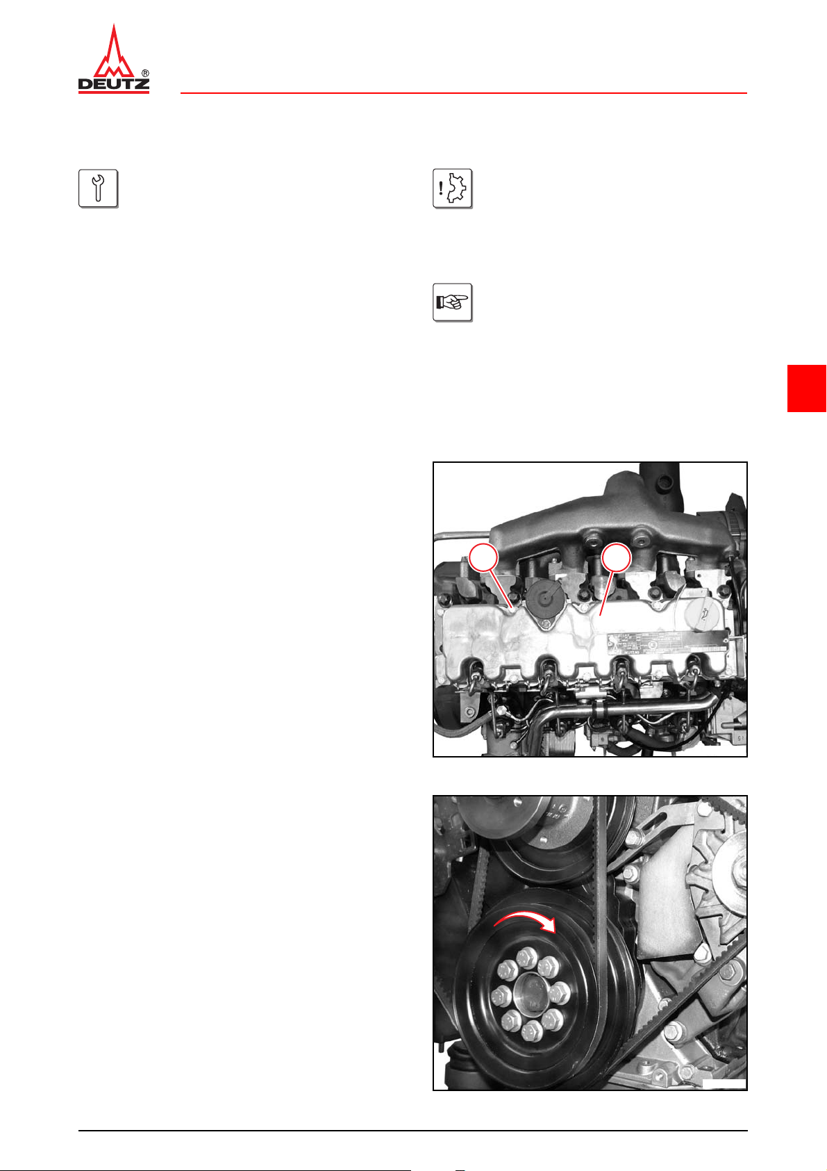
z Unscrew all screws (1).
z Remove cylinder head cowling (2).
z Remove gasket.
Attention!
In case of internal exhaust gas recirculation, the inlet valve is opened briefly by an
additional cam on the camshaft.
This is not to be confused with the valve
overlap.
Allow the engine to cool down for at least
30 minutes before setting the valve clearance. Engine oil temperature < 80 °C
The following work procedure describes
the setting of the valve clearance on an
inlet valve. The procedure is the same for
the setting on an outlet valve, taking into
consideration the setting dimension.
6
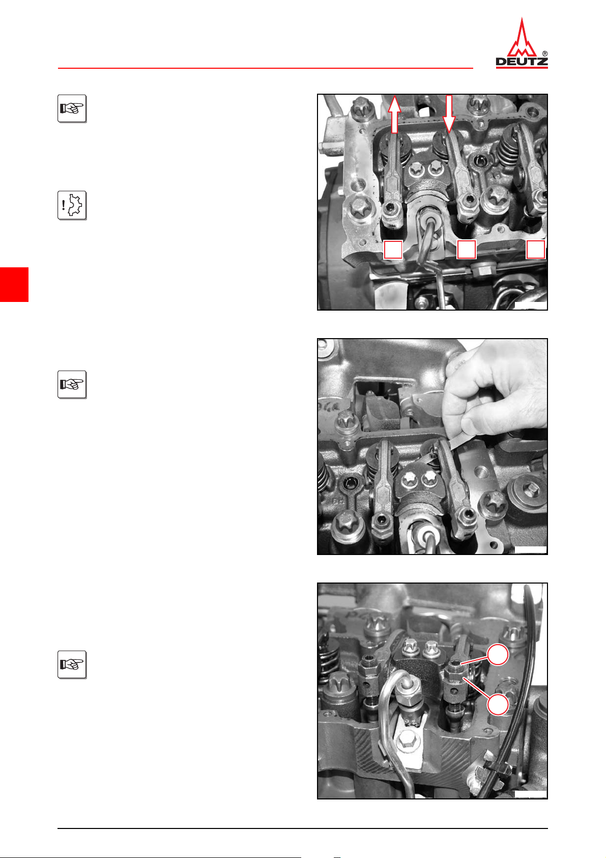
Setting engine to valve overlap
z Turn crankshaft in th e direction of the engine (arrow).
z Turn over crankshaft until the valve overlap is
achieved on cylinder 1.
© 12/2008 17770-001
1/6
Page 50
D 2011 wCylinder head
© 47542-0
© 47543-0
© 47544-0
TD 2011 w, TCD 2011 wW 01-01-01
Arrangement of the inlet and exhaust valves.
IN = inlet valve
EX = exhaust valve
Valve overlap means:
The inlet valve starts opening,exhaust
valve closes.
Attention!
In case of internal exhaust gas recirculation, the inlet valve is opened briefly by an
additional cam on the camshaft.
This is not to be confused with the valve
overlap.
EX
IN
EX
6
z Select feeler gauge.
z Check the setting on the appropriate valve.
The feeler gauge must pass between the
rocker arm's sliding surface and the valve
without too much resistance.
Setting valve clearance
z Loosen lock nut (1).
z Hold adjusting screw (2).
z Set valve clearance.
If there is not enough valve clearance, unscrew setting screw (2).
If there is too much valve clearance, turn in
setting screw (2).
–Inlet
2
1
0.3 mm
–Outlet
0.5 mm
© 12/2008 17770-001
2/6
Page 51

D 2011 w Cylinder head
© 47543-1
2
1
© 47544-0
© 47543-0
TD 2011 w, TCD 2011 w W 01-01-01
z Check the valve clearance with feeler gau ge(1).
1
6
z Hold adjusting screw (2).
z Tighten lock nut (1).
20 Nm
Do not turn the setting screw when tightening the locking nut.
z Check the valve clearance again with feeler gauge.
© 12/2008 17770-001
3/6
Page 52

D 2011 wCylinder head
© 25894-5
© 47567-0
TD 2011 w, TCD 2011 wW 01-01-01
Valve clearance setting schematic
According to the order given below, the
setting of the valve clearance is possible in
two turns of the crankshaft (each 360°).
Crankshaft position 1
z Turn over crankshaft until the valve overlap is
achieved on cylinder 1.
z Set black marked valves.
6
Crankshaft position 2
z Turn the crankshaft one turn (360°).
z Set black marked valves.
z Clean sealing surfaces.
z Mount new gasket.
Note installation position: The bar (1) must
face the front cover.
1
© 12/2008 17770-001
4/6
Page 53

D 2011 w Cylinder head
© 47540-1
TD 2011 w, TCD 2011 w W 01-01-01
z Mount cylinder head cover.
z Oil the screws lightly.
z Tighten all screws (1) alternately.
8.5 Nm
1
6
© 12/2008 17770-001
5/6
Page 54

D 2011 wCylinder head
TD 2011 w, TCD 2011 wW 01-01-01
Technical Data
Testing and setting data
ID no. Name Additional information Value
P00 71 Ignition sequence 1-3-4-2
P01 61 Valve clearance (inlet) 0.3 mm
P01 62 Valve clearance (outlet) 0.5 mm
Tightening specifications
ID no. Name Screw type Notes / Remark Value
A01 003 Lockin g nut, va lve adju ste r 20 Nm
A01 004 Cylinder head cover on cylinder head 8.5 Nm
6
For the tightening procedure according to torque using a torque wrench, a maximum variation of the
tightening torque of +/- 10% is permissible.
© 12/2008 17770-001
6/6
Page 55

D 2011 w Cylinder head
2
1
© 47540-0
© 47544-1
TD 2011w, TCD 2011 w W 01-02-02
Removing and installing the rocker arm and rocker arm bracket
Commercial available tools:
– Torx tool set . . . . . . . . . . . . . . . . . . 8189
Removing the rocker arm and rocker arm
bracket
z Unscrew all screws (1).
z Remove cylinder head cowling (2).
z Remove gasket.
– W 01-01-01
6
z Unscrew screws (1).
Loosen screws evenly to avoid tension on
the rocker arm brackets.
z Remove rocker arm bracket (2).
Lay out components in the order in which
they should be installed.
Note order of cylinders.
© 12/2008 17771-001
1/4
1
2
Page 56

D 2011 wCylinder head
© 47565-0
11
© 47565-0
© 47591-0
TD 2011w, TCD 2011 wW 01-02-02
z Remove push rods(1).
Lay out components in the order in which
they should be installed.
z Visually inspect the components.
11
6
Installing the rocker arm and rocker arm
bracket
z Insert stop rods (1).
Note the assignment of the stop rods.
The stop rod must be seated with the ball
head in the ladle of the tappet.
z Loosen lock nut (1).
z Unscrew setting screws (2).
z Mount rocker arm bracket (3).
z Position rocker arm.
The ball heads (4) must be seated in the
ladles of the stop rods.
The rocker arm (arrow) must sit on the
valve stem.
3
1
2
4
© 12/2008 17771-001
2/4
Page 57

D 2011 w Cylinder head
© 47566-0
1
© 47567-0
© 47540-1
TD 2011w, TCD 2011 w W 01-02-02
z Lightly oil screws (1).
z Tighten screws .
21 Nm
Attention!
Makes sure that the stop rods are not
under stress due to valve overlap when
fastening the screws.
z Set valve clearance.
W 01-01-01
1
6
z Clean sealing surfaces.
z Mount new gasket.
Note installation position: The bar (1) must
face the front cover.
z Mount cylinder head cover.
z Oil the screws lightly.
z Tighten all screws (1) alternately.
8.5 Nm
1
© 12/2008 17771-001
3/4
Page 58

D 2011 wCylinder head
TD 2011w, TCD 2011 wW 01-02-02
Technical Data
Tightening specifications
ID no. Name Screw type Notes / Remark Value
A01 002 Rocker arm bracket on cylinder head 21 Nm
A01 004 Cylinder head cover on cylinder head 8.5 Nm
For the tightening procedure according to torque using a torque wrench, a maximum variation of the
tightening torque of +/- 10% is permissible.
6
© 12/2008 17771-001
4/4
Page 59

D 2011 w Cylinder head
© 39144-1
© 39145-1
TD 2011 w, TCD 2011 w W 01-02-06
Disassembling, assembling and checking the rocker arm and rocker arm bracket
Commercial available tools:
– Internal measuring device
– Micrometer gauge
– Locking ring pliers
Special tools:
– Dial gauge. . . . . . . . . . . . . . . . . . 100400
Disassembling the rocker arm bracket
z Remove rocker arm and rocker arm bracket.
W 01-02-02
z Remove locking ring (1).
– W 01-02-02
6
1
1
z Remove rocker arm.
Lay out components in the order in which
they should be installed.
© 12/2008 17772-001
1/6
Page 60

D 2011 wCylinder head
© 47031-0
© 39147-1
© 47031-1
TD 2011 w, TCD 2011 wW 01-02-06
z Hold adjusting screw (2).
z Loosen lock nut (1).
z Unscrew adjusting screw (2).
2
1
Lay out components in the order in which
they should be installed.
6
z Visually inspect the components.
z Check oil channels (arrows) for free passage.
z Screw in setting screw (1).
z Screw in locking nut (2).
1
2
© 12/2008 17772-001
2/6
Page 61

D 2011 w Cylinder head
© 34768-2
© 39032-1
+0.27
+0.27
© 39148-1
+0.01
−0.01
TD 2011 w, TCD 2011 w W 01-02-06
Checking the rocker arm
z Prepare internal measuring device:
– Mount probe bolt for the appropriate measuring
range in the internal measuring device.
– Mount dial gauge with approx. 1 mm pre-tension in
the internal measuring device.
– Set micrometer gauge to 18 mm.
– Balance the internal measuring device between
the test surfaces of the micrometer gauge and set
the dial gauge at the reversal point of the pointer to
"0".
6
z Insert internal measuring device.
z Measure rocker arm bore.
–Outlet
18 mm
–Inlet
18 mm
When the wear limit is reached the rocker
arm must be renewed.
Checking the rocker arm pin
z Measure diameter with micrometer gauge .
17,97 mm
When the wear limit is reached the rocker
arm bracket must be replaced.
© 12/2008 17772-001
3/6
Page 62

D 2011 wCylinder head
© 39149-2
© 39150-1
TD 2011 w, TCD 2011 wW 01-02-06
Assembling the rocker arm bracket
z Lightly oil the rocker arm pin.
z Push rocker arm (1) onto rocker arm pin.
1
6
z Insert new locking rings (1).
Ensure that the installation location is free
from faults.
z Install rocker arm and rocker arm bracket.
W 01-02-02
1
1
© 12/2008 17772-001
4/6
Page 63

D 2011 w Cylinder head
+0.27
+0.27
+0.01
−0.01
TD 2011 w, TCD 2011 w W 01-02-06
Technical Data
Testing and setting data
ID no. Name Additional information Value
P01 72 Rocker arm, bore, diameter (outlet)
P01 73 Rocker arm, bore, diameter (inlet)
P01 74 Rocker arm pin, diameter
18 mm
18 mm
17,97 mm
6
© 12/2008 17772-001
5/6
Page 64

D 2011 wCylinder head
TD 2011 w, TCD 2011 wW 01-02-06
6
© 12/2008 17772-001
6/6
Page 65

D 2011 w Cylinder head
© 47551-1
TD 2011 w, TCD 2011 w W 01-04-04
Removing and installing cylinder head
Commercial available tools:
– Socket wrench insert Torx
E18 . . . . . . . . . . . . . . . . . . . . . . . . . 8116
– Dog wrench. . . . . . . . . . . . . . . . . . . 8018
– Rotation angle disc . . . . . . . . . . . . . 8190
Special tools:
– Plugs/caps . . . . . . . . . . . . . . . . . 170160
– W 01-02-02
– W 01-04-09
– W 06-02-03. . . . . . . . . . . .TD 2011 w,
TCD 2011 w
– W 06-07-03. . . . . . . . . . . .D 2011 w
– W 06-09-08. . . . . . . . . . . .TD 2011 w,
TCD 2011 w
– W 09-08-04
Attention!
Pay attention to utmost cleanliness when
working on the fuel system.
Remove residue paint and particles of dirt
before removing.
Clean the respective affected parts carefully. Blow damp areas dry with compressed air.
Observe the safety regulations and natio nal specifications for handling fuels.
Close all connections immediately after
opening with new, clean plugs/caps.
Do not remove plugs/caps until immediately before assembling.
Collect leaking operating substances in
suitable vessels and dispose of according
to regulations.
After all work on the fuel system, it must be
bleeded - see the operation manual, chapter "6 Fuel system“.
6
Removing the cylinder head
z Unscrew screws (1).
1
© 12/2008 17773-001
1/8
Page 66

D 2011 wCylinder head
© 47550-0
1
1
© 47547-0
© 47548-0
TD 2011 w, TCD 2011 wW 01-04-04
z Unscrew lock nuts (1) with dog wrench.
z Remove thermostat housing.
W 09-08-04
– D 2011 w
z Remove the air intake pipe.
1
W 06-07-03
– TD 2011 w, TCD 2011 w
z Remove the charge air pipe.
W 06-02-03
z Remove exhaust gas collection pipe.
1
W 06-09-08
6
z Remove rocker arm and rocker arm bracket.
W 01-02-02
z Remove push rods(1).
Lay out components in the order in which
they should be installed.
Note order of cylinders.
z Unscrew all screws (1) with the socket wrench insert.
z Remove cylinder head.
z Remove gasket.
z Visually inspect the components.
1
© 12/2008 17773-001
2/8
Page 67

D 2011 w Cylinder head
© 47552-0
© 47552-1
© 47552-1
TD 2011 w, TCD 2011 w W 01-04-04
Installing the cylinder head
Measure the piston overhang on all
pistons.
Select cylinder head gasket according to
the largest piston projection measured .
z Check piston overhang.
W 01-04-09
6
z Select cylinder head gasket according to the la rg est
piston projection measured.
– 1 recess
0.325 - 0.604 mm
– 2 recesses
0.605 - 0.704 mm
– 3 recesses
0.705 - 0.804 mm
Example:Piston overhang = 0.7 mm, corresponds to cylinder head gasket with 2
recesses (arrow).
– Recess cylinder head
z Select cylinder head gasket according to the la rg est
piston projection measured.
– 1 recess
9.820 - 10.140 mm
– 2 recesses
10.141 - 10.239 mm
– 3 recesses
10.240 - 10.310 mm
Example:Piston overhang = 10.150 mm,
corresponds to cylinder head gasket with 2
recesses (arrow).
z Remove the measuring device and holders.
© 12/2008 17773-001
3/8
Page 68

D 2011 wCylinder head
© 47549-0
1
© 47549-1
© 47548-0
TD 2011 w, TCD 2011 wW 01-04-04
z Clean sealing surfaces.
The sealing surfaces for the cylinder head
gasket must be clean and free of oil.
1
1
Make sure the clamping bushings (1) are
in place.
6
z Fit a new cylinder head gasket.
Label OBEN / TOP facing the cylinder
head.
z Fit cylinder head.
z Oil the cylinder head screws slightly.
Attention!
Screws can be reused a maximum 3 times
with written documentation.
1
z Fasten all screws (1).
© 12/2008 17773-001
4/8
Page 69

D 2011 w Cylinder head
10
3 1
8
6 4
2
5
7
9
© 39154-2
1
1
© 47547-0
© 47550-1
TD 2011 w, TCD 2011 w W 01-04-04
z Tighten cylinder head screws with socket wrench in-
sert according to the tightening sequence.
– Stage 1:
30 Nm
– Stage 2:
80 Nm
– Stage 3:
160 Nm
– Stage 4:
90°
6
z Insert stop rods (1).
z Install rocker arm and rocker arm bracket.
W 01-02-02
– D 2011 w
z Install the air intake pipe.
W 06-07-03
– TD 2011 w, TCD 2011 w
z Install the charge air pip e.
W 06-02-03
z Install exhaust gas collection pipe.
W 06-09-08
z Install thermostat housing.
W 09-08-04
z Mount new injection lines (1).
1
1
z Tighten union nuts (2) with claw spanner.
25 Nm
2
© 12/2008 17773-001
5/8
Page 70

z Position clamping claws (1).
© 47551-0
Attention!
Install tension-free.
z Tighten screws (2).
D 2011 wCylinder head
TD 2011 w, TCD 2011 wW 01-04-04
2
21 Nm
1
6
© 12/2008 17773-001
6/8
Page 71

D 2011 w Cylinder head
TD 2011 w, TCD 2011 w W 01-04-04
Technical Data
Testing and setting data
ID no. Name Additional information Value
P02 75 Piston overhang
P02 76 Piston overhang
P02 77 Piston overhang
Recess cylinder head
P02 75 Piston overhang
P02 76 Piston overhang
P02 77 Piston overhang
Tightening specifications
Identification, cylinder head gasket
= 1 recess
Identification, cylinder head gasket
= 2 recesses
Identification, cylinder head gasket
= 3 recesses
Identification, cylinder head gasket
= 1 recess
Identification, cylinder head gasket
= 2 recesses
Identification, cylinder head gasket
= 3 recesses
0.325 - 0.604 mm
0.605 - 0.704 mm
0.705 - 0.804 mm
9.820 - 10.140 mm
10.141 - 10.239 mm
10.240 - 10.310 mm
6
ID no. Name Screw type Notes / Remark Value
Stage 1:
Cylinder head screws
can be used a maximum
of 3x with written docu-
A01 001 Cylinder head on crankcase
A01 001 Cylinder head on crankcase Stage 2 80 Nm
A01 001 Cylinder head on crankcase Stage 3 160 Nm
A01 001 Cylinder head on crankcase Stage 4 90°
A07 003
A09 020 Pipe clip on holder M6x16 21 Nm
Injection line on fuel injector / injection
pump
For the tightening procedure according to torque using a torque wrench, a maximum variation of the
tightening torque of +/- 10% is permissible.
M12x1.5 25 Nm
mentation.
Otherwise use new
cylinder head screws.
Observe tightening
sequence.
30 Nm
© 12/2008 17773-001
7/8
Page 72

D 2011 wCylinder head
TD 2011 w, TCD 2011 wW 01-04-04
6
© 12/2008 17773-001
8/8
Page 73

D 2011 w Cylinder head
© 39156-2
© 39158-2
TD 2011 w, TCD 2011 w W 01-04-09
Checking piston overhang
8190
Commercial available tools
Special tools:
– Dial gauge. . . . . . . . . . . . . . . . . . 100400
– Digital dial gauge . . . . . . . . . . . . 100410
– Measuring device . . . . . . . . . . . . 100750
– Holder. . . . . . . . . . . . . . . . . . . . . 150180
Checking piston overhang
z Remove cylinder head.
W 01-04-04
z Turn the crankshaft until the respective piston is just
in front of the top dead centre (arrow).
– W 01-04-04
6
z Insert dial gauge 100400 in measuring beam.
z Place spacing washers (1) on the sealing surface of
the crankcase.
z Place measuring beam (2) on the spacing washers.
z Apply stylus of the dial gauge to the crankcase seal-
ing surface with pre-tension (arrow).
2
z Adjust dial gauge to "0".
1
© 12/2008 17774-001
1/6
1
Page 74

– Recess cylinder head
© 46933-0
2
1
© 34151-2
© 39159-1
z Insert dial gauge 100410 in measuring beam.
z Place holders (1) on the sealing surface of the crank-
case.
z Place measuring beam (2) on the holders.
z Apply stylus of the dial gauge to the crankcase seal-
ing surface with pre-tension (arrow).
z Adjust dial gauge to "0".
D 2011 wCylinder head
TD 2011 w, TCD 2011 wW 01-04-09
2
6
11
z Measure at the points (1) and (2) on the piston.
Schematic representation
z Move the measuring beam.
z Apply the stylus to the piston base (arrow) under pre-
tension.
z Continue turning the crankshaft evenly until the re-
versal point of the pointer on the dial gauge is
reached.
The stylus may not be positioned on the
labelling of the piston.
Note greatest measured value.
© 12/2008 17774-001
2/6
Page 75

D 2011 w Cylinder head
© 46934-0
© 47552-1
TD 2011 w, TCD 2011 w W 01-04-09
– Recess cylinder head
z Move the measuring beam.
z Apply the stylus to the piston base (arrow) under pre-
tension.
z Continue turning the crankshaft evenly until the re-
versal point of the pointer on the dial gauge is
reached.
The stylus may not be positioned on the
labelling of the piston.
Note greatest measured value.
6
z Select cylinder head gasket according to the la rg est
piston projection measured.
– 1 recess
0.325 - 0.604 mm
– 2 recesses
0.605 - 0.704 mm
– 3 recesses
0.705 - 0.804 mm
Example:Piston overhang = 0.7 mm, corresponds to cylinder head gasket with 2
recesses (arrow).
z Remove the measuring device and spacer discs.
z Install cylinder head.
W 01-04-04
© 12/2008 17774-001
3/6
Page 76

D 2011 wCylinder head
© 47552-1
TD 2011 w, TCD 2011 wW 01-04-09
– Recess cylinder head
z Select cylinder head gasket according to the la rg est
piston projection measured.
– 1 recess
9.820 - 10.140 mm
– 2 recesses
10.141 - 10.239 mm
– 3 recesses
10.240 - 10.310 mm
Example:Piston overhang = 10.150 mm,
corresponds to cylinder head gasket with 2
6
z Remove the measuring device and holders.
z Install cylinder head.
recesses (arrow).
W 01-04-04
© 12/2008 17774-001
4/6
Page 77

D 2011 w Cylinder head
TD 2011 w, TCD 2011 w W 01-04-09
Technical Data
Testing and setting data
ID no. Name Additional information Value
P02 75 Piston overhang
P02 76 Piston overhang
P02 77 Piston overhang
D 2011 w / TD 2011 w / TCD 2011 w Recess cylinder head
P02 75 Piston overhang
P02 76 Piston overhang
P02 77 Piston overhang
Identification, cylinder head gasket
= 1 recess
Identification, cylinder head gasket
= 2 recesses
Identification, cylinder head gasket
= 3 recesses
Identification, cylinder head gasket
= 1 recess
Identification, cylinder head gasket
= 2 recesses
Identification, cylinder head gasket
= 3 recesses
0.325 - 0.604 mm
0.605 - 0.704 mm
0.705 - 0.804 mm
9.820 - 10.140 mm
10.141 - 10.239 mm
10.240 - 10.310 mm
6
For the tightening procedure according to torque using a torque wrench, a maximum variation of the
tightening torque of +/- 10% is permissible.
© 12/2008 17774-001
5/6
Page 78

D 2011 wCylinder head
TD 2011 w, TCD 2011 wW 01-04-09
6
© 12/2008 17774-001
6/6
Page 79

D 2011 w Crankcase
© 47152-0
© 47153-0
TD 2011 w, TCD 2011 w W 03-01-11
Removing and installing the crankcase bleeding
Commercial available tools
Special tools:
– Disassembly tool. . . . . . . . . . . . . 110901
6
Removing the crankcase bleeding
z Unscrew screw (1).
z Remove crankcase bleeding (2).
z Remove the O-ring (1) with the disassembly tool.
z Visually inspect the components.
1
2
1
© 12/2008 17790-001
1/4
Page 80

D 2011 wCrankcase
© 47160-0
© 47152-0
TD 2011 w, TCD 2011 wW 03-01-11
Install crankcase bleeding
z Clean sealing surfaces.
z Insert new O-ring (1).
1
6
z Mount crankcase vent (2).
Ensure that the installation location is free
from faults.
The crankcase bleeding must fit evenly.
z Tighten screw (1).
8.5 Nm
1
2
© 12/2008 17790-001
2/4
Page 81

D 2011 w Crankcase
TD 2011 w, TCD 2011 w W 03-01-11
Technical Data
Tightening specifications
ID no. Name Screw type Notes / Remark Value
Crankcase bleeding on front cover /
A03 060
on cylinder head cover / on cylinder
head
For the tightening procedure according to torque using a torque wrench, a maximum variation of the
tightening torque of +/- 10% is permissible.
8.5 Nm
6
© 12/2008 17790-001
3/4
Page 82

D 2011 wCrankcase
TD 2011 w, TCD 2011 wW 03-01-11
6
© 12/2008 17790-001
4/4
Page 83

D 2011 w Exhaust system/Charging
1
1
12
1
© 47523-1
© 47525-1
TD 2011 w, TCD 2011 w W 06-01-05
Removing and installing the exhaust line
Commercial available tools:
– Torx tool set . . . . . . . . . . . . . . . . . . 8189
Removing exhaust line
– TD 2011 w, TCD 2011 w
z Remove turbocharger.
W 06-06-04
z Unscrew all screws (1).
z Remove exhaust line (2).
– W 06-06-04
6
z Remove gaskets (1).
© 12/2008 17805-001
1
1/4
Page 84

D 2011 wExhaust system/Charging
© 47524-0
1
1
2
2
© 47524-1
© 47523-2
TD 2011 w, TCD 2011 wW 06-01-05
z Unscrew studs (1).
z Visually inspect the components.
1
1
6
Installing exhaust line
z Clean sealing surfaces.
z Turn on new pin bolts (1).
z Tighten pin bolts (1).
12 Nm
z Clean sealing surfaces.
z Mount exhaust line (1).
z Mount new gaskets.
Note installation position.
21
2
z Turn in new screws (2).
z Tighten new screws (2).
55 Nm
– TD 2011 w, TCD 2011 w
z Install the turbocharger.
2
2
W 06-06-04
© 12/2008 17805-001
2/4
Page 85

D 2011 w Exhaust system/Charging
TD 2011 w, TCD 2011 w W 06-01-05
Technical Data
Tightening specifications
ID no. Name Screw type Notes / Remark Value
A06 001 Exhaust pipe at cylinder head
A06 004 Pin bolts on exhaust pipe coated Use new pin bolts 12 Nm
For the tightening procedure according to torque using a torque wrench, a maximum variation of the
tightening torque of +/- 10% is permissible.
Torx screw,
coated
Use new screws. 55 Nm
6
© 12/2008 17805-001
3/4
Page 86

D 2011 wExhaust system/Charging
TD 2011 w, TCD 2011 wW 06-01-05
6
© 12/2008 17805-001
4/4
Page 87

TD 2011 w, TCD 2011 w W 06-02-03
1
1
1
1
2
1
© 47525-2
© 47533-0
Removing and install the charge air line
Exhaust system/Charging
Commercial available tools:
– Torx tool set . . . . . . . . . . . . . . . . . . 8189
Remove charge air line
z Remove turbocharger.
W 06-06-04
z Remove the exhaust pipe.
W 06-01-05
– W 06-06-04
– W 06-01-05
6
z Unscrew all screws (1).
z Remove charge air pipe (2).
z Remove seals.
z Clean sealing surfaces.
© 12/2008 17806-001
1/4
Page 88

Exhaust system/Charging
© 47525-3
TD 2011 w, TCD 2011 wW 06-02-03
Install charge air line
z Mount charge air line (1).
z Mount new gaskets.
z Tighten screws (2) alternately working from the cen-
tre to the outside.
21 Nm
z Install the exhaust pipe.
W 06-01-05
z Install the turbocharger.
W 06-06-04
2
1
2
2
2
2
6
© 12/2008 17806-001
2/4
Page 89

Exhaust system/Charging
TD 2011 w, TCD 2011 w W 06-02-03
Technical Data
Tightening specifications
ID no. Name Screw type Notes / Remark Value
A06 030 Charge air pipe on cylinder head
For the tightening procedure according to torque using a torque wrench, a maximum variation of the
tightening torque of +/- 10% is permissible.
Torx screw,
coated
Use new screws. 21 Nm
6
© 12/2008 17806-001
3/4
Page 90

Exhaust system/Charging
TD 2011 w, TCD 2011 wW 06-02-03
6
© 12/2008 17806-001
4/4
Page 91

TD 2011 w, TCD 2011 w W 06-06-04
1
3
4
2
© 47532-0
© 47553-0
Removing and installing the turbocharger
Exhaust system/Charging
Commercial available tools:
– Clamping tongs. . . . . . . . . . . . . . . . 9088
– Spring band pliers. . . . . . . . . . . . . . 9090
– Lubricating oil
– Fitting compound
DEUTZ S1
Removing turbocharger
z Unscrew screw (1).
z Remove the holder (2).
z Remove oil return pipe (3).
z Unscrew hollow screw (4).
z Remove sealing rings.
Attention!
Do not remove the stoppers/caps until
immediately before assembly.
Collect leaking operating substances in
suitable vessels and dispose of according
to regulations.
6
z Loosen hose clip (1) with clamping tongs.
z Pull off hose clip (1) in the direction of the arrow.
© 12/2008 17807-001
1/8
1
Page 92

Exhaust system/Charging
© 47554-0
1
2
© 47526-0
© 47527-0
TD 2011 w, TCD 2011 wW 06-06-04
z Loosen spring band clip (1) with spring band pliers.
z Remove reducer (2).
2
1
6
z Unscrew hollow screw (1).
z Remove lubricating oil pipe (2).
z Remove sealing rings.
z Press in stoppers.
z Loosen spring band clip (1) with spring band pliers.
z Pull off spring band clip (1) in the direction of the ar-
row.
1
© 12/2008 17807-001
2/8
Page 93

TD 2011 w, TCD 2011 w W 06-06-04
© 47528-0
1
© 47555-0
© 47529-0
z Unscrew nuts (1).
Exhaust system/Charging
1
1
6
z Remove turbocharger in the direction of the arrow.
z Remove gasket (1).
z Remove the O-ring (1) with the disassembly tool.
z Unscrew screw-in nipple (2).
z Remove sealing ring (3).
2
3
1
© 12/2008 17807-001
3/8
Page 94

Exhaust system/Charging
© 47523-0
3
2
1
© 47529-1
© 47523-0
TD 2011 w, TCD 2011 wW 06-06-04
z Unscrew studs (1).
z Check components for visible signs of wear.
1
1
6
Installing the turbocharger
z Mount sealing ring (1).
z Tighten screw-in nipple (2).
40 Nm
z Insert new O-ring (3).
z Clean sealing surfaces.
z Coat pin bolts with mounting compound.
z Screw in studs (1).
z Tighten all pin bolts (1).
12 Nm
1
1
© 12/2008 17807-001
4/8
Page 95

TD 2011 w, TCD 2011 w W 06-06-04
© 47555-1
2
1
2
© 47528-1
© 47527-0
z Mount gasket (1).
z Plug in the tubing connection (2).
z Insert turbocharger in the direction of the arrow.
Exhaust system/Charging
z Mount turbocharger (1).
z Turn on new nuts (2).
z Tighten nuts (2).
21 Nm
2
1
6
z Position the spring band clip (1) with the spring band
pliers.
z Pull out stoppers.
z Fill in clean lubricating oil (arrow).
1
© 12/2008 17807-001
5/8
Page 96

Exhaust system/Charging
© 47526-1
© 39378-2
© 47532-1
TD 2011 w, TCD 2011 wW 06-06-04
z Mount lubrication oil line (1).
z Mount sealing rings (2).
z Screw on hollow screw (3).
3
2
1
6
z Insert new O-ring (1).
z Lightly oil new O-ring (1).
z Mount oil return pipe (1).
z Mount holder (2).
z Tighten screw (3).
8.5 Nm
Attention!
Install tension-free.
1
4
1
z Mount new sealing rings (4).
z Tighten hollow screw (5).
5
2
3
© 12/2008 17807-001
6/8
Page 97

TD 2011 w, TCD 2011 w W 06-06-04
© 47526-2
2
1
© 47554-1
© 47553-1
Attention!
Install tension-free.
z Tighten hollow screw (1).
29 Nm
Exhaust system/Charging
1
6
z Mount the reducer (1).
Attention!
Install tension-free.
z Position spring band clip (2) with spring band pliers.
z Position hose clip (1) with clamping tongs.
© 12/2008 17807-001
7/8
1
Page 98

Exhaust system/Charging
TD 2011 w, TCD 2011 wW 06-06-04
Technical Data
Tightening specifications
ID no. Name Screw type Notes / Remark Value
A06 004 Pin bolts on exhaust pipe coated Use new pin bolts 12 Nm
A06 020 Turbocharger on exhaust pipe M8 21 Nm
A08 042
A08 044
A08 049 Holder oil return line on crankcase
Lubricating oil pipe on turbocharger /
crankcase
Oil return line, hex spuds to turbocharger
Hollow screw Replace sealing rings 29 Nm
M16x1.5 Use new sealing ring 40 Nm
Torx,
M6x14-8.8
8.5 Nm
6
For the tightening procedure according to torque using a torque wrench, a maximum variation of the
tightening torque of +/- 10% is permissible.
© 12/2008 17807-001
8/8
Page 99

D 2011 w W 06-07-03
1
1
11
2
© 47645-0
© 47533-0
Removing and installing the intake manifold
Exhaust system/Charging
Commercial available tools:
– Torx tool set . . . . . . . . . . . . . . . . . . 8189
Removing the intake manifold
z Remove the exhaust pipe.
W 06-01-05
z Unscrew all screws (1).
z Remove intake manifold (2).
z Remove seals.
– W 06-01-05
6
z Clean sealing surfaces.
© 12/2008 17808-001
1/4
Page 100

Exhaust system/Charging
© 47645-1
Installing the intake manifold
D 2011 wW 06-07-03
z Mount new gaskets.
z Mount intake manifold (1).
z Tighten new screws (2) alternately working from the
centre to the outside.
21 Nm
z Install the exhaust pipe.
W 06-01-05
2
2
1
22
6
© 12/2008 17808-001
2/4
 Loading...