


Denon SYS-T3L, SYS-C3L, SYS-A3L, SYSA2-1L, SC-T3L Service Manual
...For U.S.A., Canada, Europe & Japan model
Ver. 2
SERVICE MANUAL
MODEL SYS-T3L/SYS-C3L SYS-A3L/SYS-A2.1L
SPEAKER SYSTEM PACK
SC-T3L/SC-A3L
SPEAKER SYSTEM
DSW-3L
SUPER WOOFER
|
●For purposes of improvement, specifications and design are subject to change without notice.
●Please use this service manual with referring to the operating instructions without fail.
●Some illustrations using in this service manual are slightly different from the actual set.
● ● 8
●
●
16-11, YUSHIMA 3-CHOME, BUNKYO-KU, TOKYO 113-0034 JAPAN
X0194V.02 DE/CDM 0311
SYS-T3L/SYS-C3L/SYS-A3L/SYS-A2.1L/SC-T3L/SC-A3L/DSW-3L 2
SAFETY PRECAUTIONS
The following check should be performed for the continued protection of the customer and service technician.
LEAKAGE CURRENT CHECK
Before returning the unit to the customer, make sure you make either (1) a leakage current check or (2) a line to chassis resistance check. If the leakage current exceeds 0.5 milliamps, or if the resistance from chassis to either side of the power cord is less than 460 kohms, the unit is defective.
 500V
500V


 1M
1M


(1) 


(2) 


(1)

(2)

2
SYS-T3L/SYS-C3L/SYS-A3L/SYS-A2.1L/SC-T3L/SC-A3L/DSW-3L |
3 |
|
|
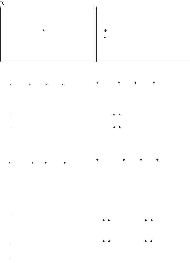
NOTE FOR PARTS LIST
l Part indicated with the mark " " are not always in stock and possibly to |
|
take a long period of time for supplying, or in some case supplying of |
|
part may be refused. |
|
l When ordering of part, clearly indicate "1" and "I" (i) to avoid mis- |
|
supplying. |
|
l Ordering part without stating its part number can not be supplied. |
|
l Part indicated with the mark " " is not illustrated in the exploded view. |
|
l Not including Carbon Film Resister ±5%, 1/4W Type in the P.W.Board |
|
parts list. (Refer to the Schematic Diagram for those parts.) |
|
l Not including Carbon Chip Resister 1/16W Type in the P.W.Board parts |
5% 1/4W |
list. (Refer to the Schematic Diagram for those parts.) |
|
WARNING: |
1/16W |
Parts marked with this symbol  have critical characteristics.
Use ONLY replacement parts recommended by the manufacturer.
l Resistors
Ex.: |
RN |
14K |
|
|
2E |
182 |
|
G |
|
FR |
||||||||
|
|
Type |
Shape Power ResistAllowable |
Others |
||||||||||||||
|
|
|
|
|
and per- |
|
ance |
error |
|
|
|
|||||||
|
|
|
|
|
|
|
|
|
||||||||||
|
|
|
|
|
formance |
|
|
|
|
|
|
|
|
|
||||
|
|
|
|
|
|
|
|
|
|
|
|
|
|
|||||
|
|
|
|
|
|
|
|
|
|
|
|
|
|
|
|
|
|
|
|
|
|
|
|
|
|
|
|
|
|
|
|
||||||
RD |
: Carbon |
|
|
|
|
2B |
: 1/8W |
|
F |
: ±1% |
P |
: Pulse-resistant type |
||||||
RC |
: Composition |
|
|
|
2E : 1/4W |
|
G |
: ±2% |
NL : Low noise type |
|||||||||
RS |
: Metal oxide film |
|
|
|
2H : 1/2W |
|
J |
: ±5% |
NB : Non-burning type |
|||||||||
RW : Winding |
|
|
|
|
3A : 1W |
|
K |
: ±10% |
FR : Fuse-resistor |
|||||||||
RN |
: Metal film |
|
|
|
3D : 2W |
|
M |
: ±20% |
F |
: Lead wire forming |
||||||||
RK |
: Metal mixture |
|
|
|
3F |
: 3W |
|
|
|
|
|
|
|
|||||
|
|
|
|
|
|
|
|
|
3H : 5W |
|
|
|
|
|
|
|
||
|
|
|
|
|
|
|
|
|
|
|
|
|
|
|
||||
] Resistance |
|
|
|
|
|
|
|
|
|
|
|
|
|
|
||||
1 |
|
8 |
2 |
|
|
|
1800 ohm = 1.8 kohm |
|
|
|
||||||||
s |
|
s |
|
|
|
Indicates number of zeros after effective number. |
||||||||||||
|
|
|
|
|
|
|
|
|||||||||||
|
|
|
|
|
|
|
|
2-digit effective number. |
|
|
|
|||||||
• Units: ohm |
|
|
|
|
|
|||||||||||||
|
|
|
|
|
|
|
|
|
|
|
|
|
|
|||||
1 |
|
R |
2 |
|
|
|
1.2 ohm |
|
|
|
|
|
|
|||||
s |
s |
|
|
|
1-digit effective number. |
|
|
|
||||||||||
|
|
|
|
|
|
|
|
|
|
|
||||||||
|
|
|
|
|
|
|
|
2-digit effective number, decimal point indicated by R. |
||||||||||
• Units: ohm |
|
|
|
|||||||||||||||
|
|
|
|
|
|
|
|
|
|
|
|
|
|
|||||
|
|
|
RN |
14K |
|
|
|
|
2E |
|
|
|
|
182 |
|
|
|
G |
|
|
FR |
|||||||||||||
|
|
|
|
|
|
|
|
|
|
|
|
|
|
|
|
|
|
|
|
|
|
|
|
|
|
|
|
|
|
|
|
|
|
|
|
|
|
|
|
|
|
|
|
|
|
|
|
|
|
|
|
|
|
|
|
|
|
|
|
|
|
|
|
|
|
|
|
|
|
|
|
|
|
|
|
|
|
|
|
|
|
|
|
|
|
|
|
|
|
|
|
|
|
|
|
|
|
|
|
|
|
|
|
|
|
|
|
|
|
|
|
|
|
|
|
|
|
|
|
|
|
|
|
|
|
|
|
|
|
|
|
|
|
|
|
|
|
|
|
RD |
: |
|
|
|
|
|
|
|
2B |
: 1/8 |
W |
|
|
F |
: |
±1% |
|
|
|
P |
: |
|
|
|
|
|||||||||
RC |
: |
|
|
|
|
|
|
|
2E |
: 1/4 |
W |
|
|
G : |
±2% |
|
|
|
NL : |
|||||||||||||||
RS |
: |
|
|
|
|
|
|
|
2H |
: 1/2 |
W |
|
|
J |
: |
±5% |
|
|
|
NB : |
||||||||||||||
RW : |
|
|
3A |
: 1 |
|
W |
|
|
K : |
±10% |
|
|
FR |
: |
|
|
|
|
||||||||||||||||
RN |
: |
|
|
|
|
|
|
|
3D |
: 2 |
|
W |
|
|
M : |
±20% |
|
|
F |
: |
|
|
|
|
||||||||||
RK |
: |
|
|
|
|
|
|
|
3F |
: 3 |
|
W |
|
|
|
|
|
|
|
|
|
|
|
|
|
|
|
|
||||||
|
|
|
|
|
|
|
|
|
|
3H |
: 5 |
|
W |
|
|
|
|
|
|
|
|
|
|
|
|
|
|
|
|
|||||
|
18 |
|
2 |
|
Ö |
|
|
1800 |
|
=1.8k |
|
|
|
|
|
|
|
|
|
|||||||||||||||
|
|
|
|
|
|
|
|
|
|
|
|
|
2 |
|
|
|
|
|
|
|
|
0 |
|
|
|
|
|
|
|
|
|
|
||
|
|
|
|
|
|
|
|
|
|
|
|
|
|
|
|
|
|
|
|
|
|
|
|
|
|
|
|
|
|
|
||||
|
|
|
|
|
|
|
|
|
|
|
|
|
|
|
|
|
|
|
|
|
|
|
|
|
|
|
|
|
|
|
||||
|
|
|
|
|
|
|
|
|
|
|
|
|
|
|
|
|
|
|
|
|
|
|
|
|
|
|
|
|
|
|
|
|||
|
|
|
|
|
|
1R |
|
|
2 |
|
|
|
|
1.2 |
|
|
|
|
|
|
|
|
|
|
|
|
|
|
||||||
|
|
|
|
|
|
|
|
Ö |
|
|
|
|
|
|
|
|
|
|
|
|
|
|
|
|
||||||||||
|
|
|
|
|
|
|
|
|
|
|
|
|
|
1 |
|
|
|
|
|
|
|
|
|
|
|
|
|
|
|
|
|
|
|
|
|
|
|
|
|
|
|
|
|
|
|
|
|
|
|
|
|
|
|
|
|
|
|
|
|
|
|
|
|
|
|
|
|
||
|
|
|
|
|
|
|
|
|
|
|
|
|
|
|
|
|
|
|
|
|
|
|
|
|
|
|
|
|
|
|
|
|
||
|
|
|
|
|
|
|
|
|
|
|
|
|
|
2 |
|
|
|
|
|
|
|
|
|
|
R |
|
|
|
|
|
||||
|
|
|
|
|
|
|
|
|
|
|
|
|
|
|
|
|
|
|
|
|
|
|
|
|
|
|
|
|
||||||
l Capacitors
Ex.: |
CE |
|
04W |
|
1H |
2R2 |
M |
|
BP |
|||||||||||||
|
Type |
|
Shape |
Dielectric Capacity Allowable Others |
||||||||||||||||||
|
|
|
|
|
|
and perstrength |
|
|
|
error |
|
|
||||||||||
|
|
|
|
|
|
formance |
|
|
|
|
|
|
|
|
|
|
|
|
|
|
||
|
|
|
|
|
|
|
|
|
|
|
|
|
|
|
|
|
|
|
|
|
|
|
|
|
|
|
|
|
|
|
|
|
|||||||||||||
CE |
: Aluminum foil |
|
0J |
: 6.3V |
F |
: ±1% |
|
|
HS : High stability type |
|||||||||||||
|
electrolytic |
|
|
|
|
|
|
|
|
|
|
: ±2% |
|
|
|
|
|
|||||
CA |
: Aluminum solid |
|
1A |
: 10V |
G |
|
|
BP : Non-polar type |
||||||||||||||
|
electrolytic |
|
|
|
|
|
|
|
|
|
|
: ±5% |
|
|
|
|
|
|||||
CS |
: Tantalum electrolytic |
1C |
: 16V |
J |
|
|
HR : Ripple-resistant type |
|||||||||||||||
CQ : Film |
|
|
|
|
|
|
|
1E |
: 25V |
K |
: ±10% |
|
|
DL : For change and discharge |
||||||||
CK |
: Ceramic |
|
|
|
|
1V |
: 35V |
M |
: ±20% |
|
|
HF : For assuring high |
||||||||||
|
|
|
|
|
|
|
|
|
|
|
|
|
|
|
|
|
|
|
|
|
requency |
|
CC : Ceramic |
|
|
|
|
1H |
: 50V |
Z |
: +80% |
|
|
U |
: UL part |
||||||||||
CP |
: Oil |
|
|
|
|
|
|
|
2A |
: 100V |
|
–20% |
|
|
C |
: CSA part |
||||||
CM : Mica |
|
|
|
|
|
|
|
2B |
: 125V |
P |
: +100% |
|
W |
: UL-CSA type |
||||||||
CF |
: Metallized |
|
|
|
2C |
: 160V |
|
–0% |
|
|
F |
: Lead wire forming |
||||||||||
CH : Metallized |
|
|
|
2D |
: 200V |
C |
: ±0.25pF |
|
|
|
||||||||||||
|
|
|
|
|
|
|
|
|
2E |
: 250V |
D |
: ±0.5pF |
|
|
|
|
|
|||||
|
|
|
|
|
|
|
|
|
2H |
: 500V |
= |
: Others |
|
|
|
|
|
|||||
|
|
|
|
|
|
|
|
|
2J |
: 630V |
|
|
|
|
|
|
|
|
||||
|
|
|
|
|
|
|
|
|
|
|||||||||||||
] Capacity (electrolyte only) |
|
|
|
|
|
|
|
|
||||||||||||||
2 |
2 |
2 |
|
|
|
2200µF |
|
|
|
|
|
|
|
|
||||||||
s |
s |
|
|
|
Indicates number of zeros after effective number. |
|||||||||||||||||
|
|
|
|
|
|
|
|
|||||||||||||||
|
|
|
|
|
|
|
|
2-digit effective number. |
|
|
|
|
|
|||||||||
• Units: µF. |
|
|
|
|
|
|
|
|
||||||||||||||
|
|
|
|
|
|
|
|
|
|
|
|
|
|
|
|
|
|
|||||
2 |
R |
2 |
|
|
|
2.2µF |
|
|
|
|
|
|
|
|
|
|
||||||
s |
s |
|
|
|
1-digit effective number. |
|
|
|
|
|
||||||||||||
|
|
|
|
|
|
|
|
|
|
|
|
|
||||||||||
|
|
|
|
|
|
|
|
2-digit effective number, decimal point indicated by R. |
||||||||||||||
• Units: µF. |
|
|
|
|||||||||||||||||||
|
|
|
|
|
|
|
|
|
|
|
|
|
|
|
|
|
|
|||||
] Capacity (except electrolyte) |
|
|
|
|
|
|
|
|
||||||||||||||
2 |
2 |
2 |
|
|
|
2200pF=0.0022µF |
|
|
|
|
|
|
|
|||||||||
s |
s |
(More than 2) |
|
|
Indicates number of zeros after effective number. |
|||||||||||||||||
|
|
|
|
|
|
|
||||||||||||||||
|
|
|
|
|
|
|
|
|
|
|
|
|
2-digit effective number. |
|
|
|||||||
• Units: pF. |
|
|
|
|
|
|
|
|
|
|
||||||||||||
|
|
|
|
|
|
|
|
|
|
|
|
|
|
|
|
|
|
|||||
2 |
2 |
1 |
|
|
|
220pF |
|
|
|
|
|
|
|
|
|
|
||||||
s |
s |
(0 or 1) |
|
|
|
|
|
Indicates number of zeros after effective number. |
||||||||||||||
|
|
|
|
|
|
|
|
|
|
|||||||||||||
|
|
|
|
|
|
|
|
|
|
|
|
|
2-digit effective number. |
|
|
|||||||
|
|
|
|
|
|
|
|
|
|
|
|
|
|
|
||||||||
•Units: pF.
•When the dielectric strength is indicated in AC, "AC" is included after the dieelectric strength value.
|
|
|
|
CE |
|
|
|
|
|
|
04W |
|
|
1H |
|
|
|
|
2R2 |
|
|
|
|
|
|
|
M |
|
|
|
|
|
|
BP |
|
|
||||||||
|
|
|
|
|
|
|
|
|
|
|
|
|
|
|
|
|
|
|
|
|
|
|
|
|
|
|
|
|
|
|
|
|
|
|
|
|
|
|
|
|
|
|
|
|
|
|
|
|
|
|
|
|
|
|
|
|
|
|
|
|
|
|
|
|
|
|
|
|
|
|
|
|
|
|
|
|
|
|
|
|
|
|
|
|
|
|
|
|
|
|
|
|
|
|
|
|
|
|
|
|
|
|
|
|
|
|
|
|
|
|
|
|
|
|
|
|
|
|
|
|
|
|
|
|
|
|
|
|
|
|
|
|
|
|
|
|
|
|
|
|
|
|
|
|
|
|
|
|
|
|
|
|
|
|
|
|
|
|
|
|
|
|
|
|
|
|
|
|
|
|
|||||||||
CE |
: |
|
|
|
|
|
|
|
|
|
|
|
0J |
: 6.3 |
V |
|
F |
: ±1% |
|
|
|
|
|
|
HS |
: |
|
|
|
|
|
|||||||||||||
CA |
: |
|
|
|
|
|
|
|
|
|
|
|
1A |
: 10 |
V |
|
G |
: ±2% |
|
|
|
|
|
|
BP |
: |
|
|
|
|
|
|||||||||||||
CS |
: |
|
|
|
|
|
|
|
|
|
|
|
1C |
: 16 |
V |
|
J |
: ±5% |
|
|
|
|
|
|
HR : |
|
|
|
|
|
||||||||||||||
CQ |
: |
|
|
|
|
|
|
|
|
|
|
|
1E |
: 25 |
V |
|
K |
: ±10% |
|
|
|
|
|
DL : |
|
|
|
|
|
|||||||||||||||
CK |
: |
|
|
|
|
|
|
|
|
|
|
|
1V |
: 35 |
V |
|
M |
: ±20% |
|
|
|
|
|
HF |
: |
|
|
|
|
|
||||||||||||||
CC |
: |
|
|
|
|
|
|
|
|
|
|
|
1H |
: 50 |
V |
|
Z |
: +80% |
|
|
|
|
|
U |
: |
UL |
|
|
||||||||||||||||
CP |
: |
|
|
|
|
|
|
|
|
|
|
|
2A |
: 100 V |
|
|
|
|
−20% |
|
|
C |
: |
CSA |
|
|
||||||||||||||||||
CM : |
|
|
|
|
|
|
|
2B |
: 125 V |
|
P |
: +100% |
|
|
|
|
W : |
UL-CSA |
|
|||||||||||||||||||||||||
CF |
: |
|
|
|
|
|
|
|
|
|
|
|
2C |
: 160 V |
|
|
|
|
− |
0% |
|
|
|
|
F |
: |
|
|
|
|
|
|||||||||||||
CH |
: |
|
|
|
|
|
|
|
|
|
|
|
2D |
: 200 V |
|
C |
: ±0.25pF |
|
|
|
|
|
|
|
|
|
|
|
|
|||||||||||||||
|
|
|
|
|
|
|
|
|
|
|
|
|
|
2E |
: 250 V |
|
D |
: ±0.5pF |
|
|
|
|
|
|
|
|
|
|
|
|
||||||||||||||
|
|
|
|
|
|
|
|
|
|
|
|
|
|
2H |
: 500 V |
|
= |
: |
|
|
|
|
|
|
|
|
|
|
|
|
|
|
|
|
|
|
|
|||||||
|
|
|
|
|
|
|
|
|
|
|
|
|
|
2J |
: 630 V |
|
|
|
|
|
|
|
|
|
|
|
|
|
|
|
|
|
|
|
|
|
|
|
|
|||||
|
|
|
|
|
|
|
|
|
|
|
|
|
|
|
|
|
|
|
|
|
|
|
|
|
|
|
|
|
|
|
|
|
|
|
|
|
|
|
|
|
|
|
|
|
|
|
|
22 |
|
|
2 |
|
Ö |
2200µF |
|
|
|
|
|
|
|
2R |
|
|
2 |
|
|
|
Ö |
|
|
2.2µF |
|
|
|||||||||||||||
|
|
|
|
|
|
|
|
|
|
|
|
|
2 |
|
|
0 |
|
|
|
|
|
|
|
|
|
|
|
|
|
|
|
|
|
1 |
|
|
|
|
|
|
|
|
||
|
|
|
|
|
|
|
|
|
|
|
|
|
|
|
|
|
|
|
|
|
|
|
|
|
|
|
|
|
|
|
|
|
|
|
|
|
|
|
|
|||||
|
|
|
|
|
|
|
|
|
|
|
|
|
|
|
|
|
|
|
|
|
|
|
|
|
|
|
|
|
|
|
|
|
2 |
|
|
|
|
|
|
|
R |
|||
|
|
|
|
|
|
|
|
|
µF |
|
|
|
|
|
|
|
|
|
|
|
|
|
|
|
|
|
|
µF |
|
|
|
|
|
|
|
|
|
|
|
|||||
|
|
|
22 |
|
|
2 |
|
Ö |
2200pF=0.0022µF |
|
|
|
22 |
|
|
1 |
|
|
|
Ö |
|
|
220pF |
|
|
|||||||||||||||||||
|
|
|
|
|
|
|
|
|
|
|
|
|
|
|
|
|
|
|
|
|
|
|||||||||||||||||||||||
|
|
|
|
|
|
|
|
|
|
|
|
|
|
|
|
0 |
|
|
|
|
|
|
|
|
|
|
|
|
|
|
|
|
|
|
|
|
|
|
|
|
|
0 |
|
|
|
|
|
|
|
|
|
|
|
(0 |
2 |
|
) |
|
|
|
|
|
|
|
|
|
|
|
|
|
|
|
|
|
|
|
|
|
|
|
|
||||||||
|
|
|
|
|
|
|
|
|
|
|
|
|
|
|
|
|
|
|
|
|
|
|
|
|
|
(0 |
|
|
|
0 |
|
|
1 |
) |
||||||||||
|
|
|
|
|
|
|
|
|
|
|
2 |
|
|
|
|
|
|
|
|
|
|
|
|
|
|
|
|
|
|
|
|
2 |
|
|
|
|
|
|
|
|
||||
|
|
|
|
|
|
|
|
|
|
|
|
|
|
|
|
|
|
|
|
|
|
|
|
|
|
|
|
|
|
|
|
|
|
|
|
|
|
|
||||||
|
|
|
|
|
|
|
|
|
pF |
|
|
|
|
|
|
|
|
|
|
|
|
|
|
|
|
|
|
pF |
|
|
|
|
|
|
|
|
|
|
|
|||||


 AC
AC


3
SYS-T3L/SYS-C3L/SYS-A3L/SYS-A2.1L/SC-T3L/SC-A3L/DSW-3L 4
NOTE FOR SCHEMATIC DIAGRAM
WARNING:
Parts marked with this symbol ! have critical characteristics. Use ONLY replacement parts recommended by the manufacturer.
 !
!
CAUTION:
Before returning the unit to the customer, make sure you make either (1) a leakage current check or (2) a line to chassis resistance check. If the leakage current exceeds 0.5 milliamps, or if the resistance from chassis to either side of the power cord is less than 460 kohms, the unit is defective.
(1)Ω Ω M MΩ
(2)F F
WARNING:
DO NOT return the unit to the customer until the problem is located and corrected.
NOTICE:
ALL RESISTANCE VALUES IN OHM. k=1,000 OHM M=1,000,000 OHM
ALL CAPACITANCE VALUES IN MICRO FARAD. P=MICRO-MICRO FARAD
EACH VOLTAGE AND CURRENT ARE MEASURED AT NO SIGNAL INPUT CONDITION.
CIRCUIT AND PARTS ARE SUBJECT TO CHANGE WITHOUT PRIOR NOTICE.
4
DSW-3L Section |
|
SYS-T3L/SYS-C3L/SYS-A3L/SYS-A2.1L/SC-T3L/SC-A3L/DSW-3L |
5 |
|
|
|
|
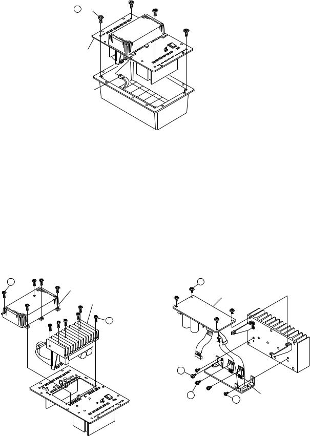
DISASSEMBLY |
|
||
(Follow the procedure below in reverse order when reassem- |
|
||
bling.) |
|
|
|
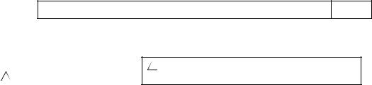
1. Speaker Unit |
1. |
||
(1) |
Remove 4 screws , detach the Base Board and Sup- |
(1) |
4 |
|
porter. |
|
|
(2) |
Remove 4 screws , detach the Speaker Unit and Grille |
(2) |
4 |
|
Ass’y. |
|
Ass'y |
(3) |
Disconnect the Connector. |
(3) |
|
1 x 4
Base Board
Supporter
2 x 4
Grille Ass'y
Speaker Unit
Connector
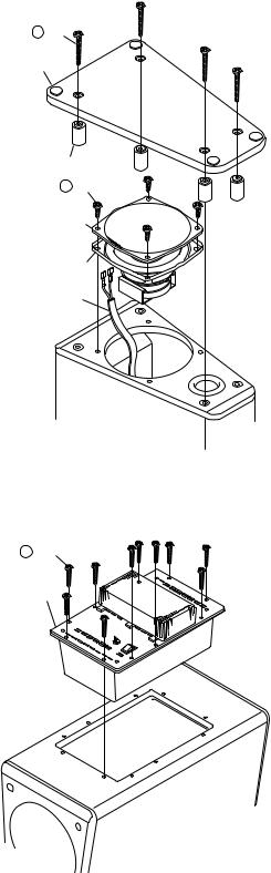
2. AMP Ass’y |
2. Ass'y |
(1) Remove 10 screws , detach the AMP Ass’y. |
(1) 10 Ass'y |
3 x 10
AMP Ass'y
5
DSW-3L Section |
|
SYS-T3L/SYS-C3L/SYS-A3L/SYS-A2.1L/SC-T3L/SC-A3L/DSW-3L |
6 |
|
|
|
|
3. Rear Panel |
3. |
||
(1) |
Remove 4 screws , detach the Rear Panel. |
(1) |
4 |
(2) |
Disconnect the Connector. |
(2) |
|
4 x 4
Rear Panel
Connector
4.Heatsink Ass’y and Each Unit
(1)Remove 5 screws , detach the Heatsink Cover.
(2)Remove 6 screws , detach the Heatsink Ass’y.
(3)Remove 4 screws , detach the AMP Unit -1.
(4)Remove 2 screws , 1 screws and 2 screws , detach the AMP Unit -2.
5 x 5
Heatsink Cover Heatsink Ass'y
4.Ass'y
(1)5
(2)6 Ass'y
(3)4 AMP -1
(4)2 1 2 AMP -2
7 x 4
AMP Unit -1
6 x 6
9
8 x 2 |
AMP Unit -2 |
|
10 x 2 |
6
DSW-3L Section |
|
SYS-T3L/SYS-C3L/SYS-A3L/SYS-A2.1L/SC-T3L/SC-A3L/DSW-3L |
7 |
|
|
|
|
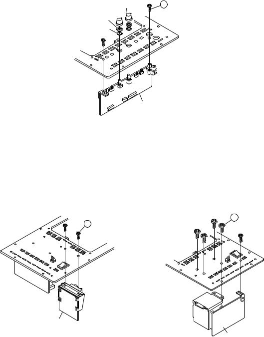
5.Per-amp Unit
(1)Detach the 2 VR Knob. remove 2 Nut and 2 Washer.
(2)Remove 2 screws , detach the Pre-amp Unit.
VR Knob
Nut
Washer
(1)2 22
(2)2
11 x 2
Pre-amp Unit
6.Each Unit
(1)Remove 2 screws , detach the Sub trans Unit.
(2)Remove 5 screws , detach the Main trans Unit.
(1)2
(2)5
13 x 5
12 x 2
Sub Trans Unit
Main Trans Unit
7
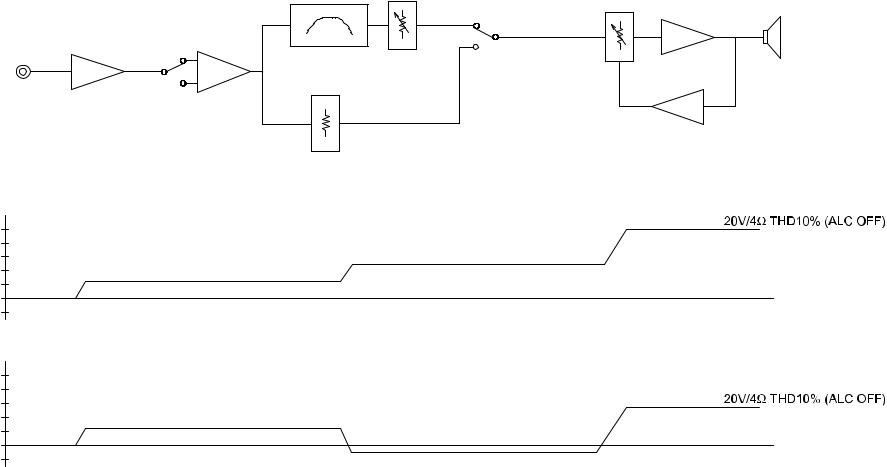
BLOCK / LEVEL DIAGRAM
NORMAL
LINE INPUT
IC501 |
IC501 |
REVERSE PHASE
(dB)
LINE
INPUT
|
40 |
|
|
20 |
+13dB |
|
0 |
53mV |
|
|
|
|
-10 |
|
LINE |
(dB) |
|
|
|
|
INPUT |
40 |
|
DIRECT |
|
|
|
|
|
MODE |
20 |
+13dB |
|
||
|
0 |
0.54V |
|
|
|
|
-10 |
|
DSW-3L Section |
|
SYS-T3L/SYS-C3L/SYS-A3L/SYS-A2.1L/SC-T3L/SC-A3L/DSW-3L |
8 |
|
|
|
|
CROSSOVER |
VOL |
S401 |
POWER AMP |
|
|
CONTROL |
SPEAKER |
||||
|
|||||
|
DIRECT |
|
|||
|
|
|
|
||
|
|
MODE SW |
|
|
|
|
|
|
IC601 |
|
|
|
|
|
ALC |
|
|
DIRECT MODE |
|
|
|
|
|
ATT |
|
|
|
|
+51dB
at 55Hz
+12dB
+32dB
at 55Hz
-1dB
8

DSW-3L Section |
|
SYS-T3L/SYS-C3L/SYS-A3L/SYS-A2.1L/SC-T3L/SC-A3L/DSW-3L |
9 |
|
|
|
|
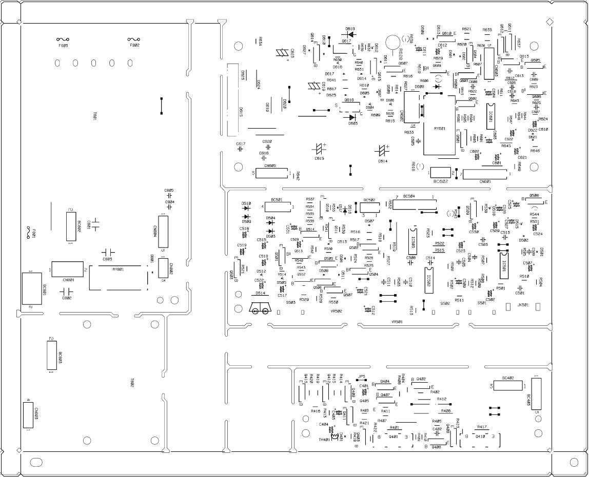
PRINTED WIRING BOARDS
MAIN P.W.B. UNIT
COMPONENT SIDE
9
|
DSW-3L Section |
|
SYS-T3L/SYS-C3L/SYS-A3L/SYS-A2.1L/SC-T3L/SC-A3L/DSW-3L |
10 |
||||
|
|
|
|
|
|
|
|
|
|
|
|
|
|
|
|
|
|
|
|
|
|
|
|
|
|
|
|
|
|
|
|
|
|
|
|
FOIL SIDE
10
 Loading...