

Page 1
For Europe model
SERVICE MANUAL
MODEL
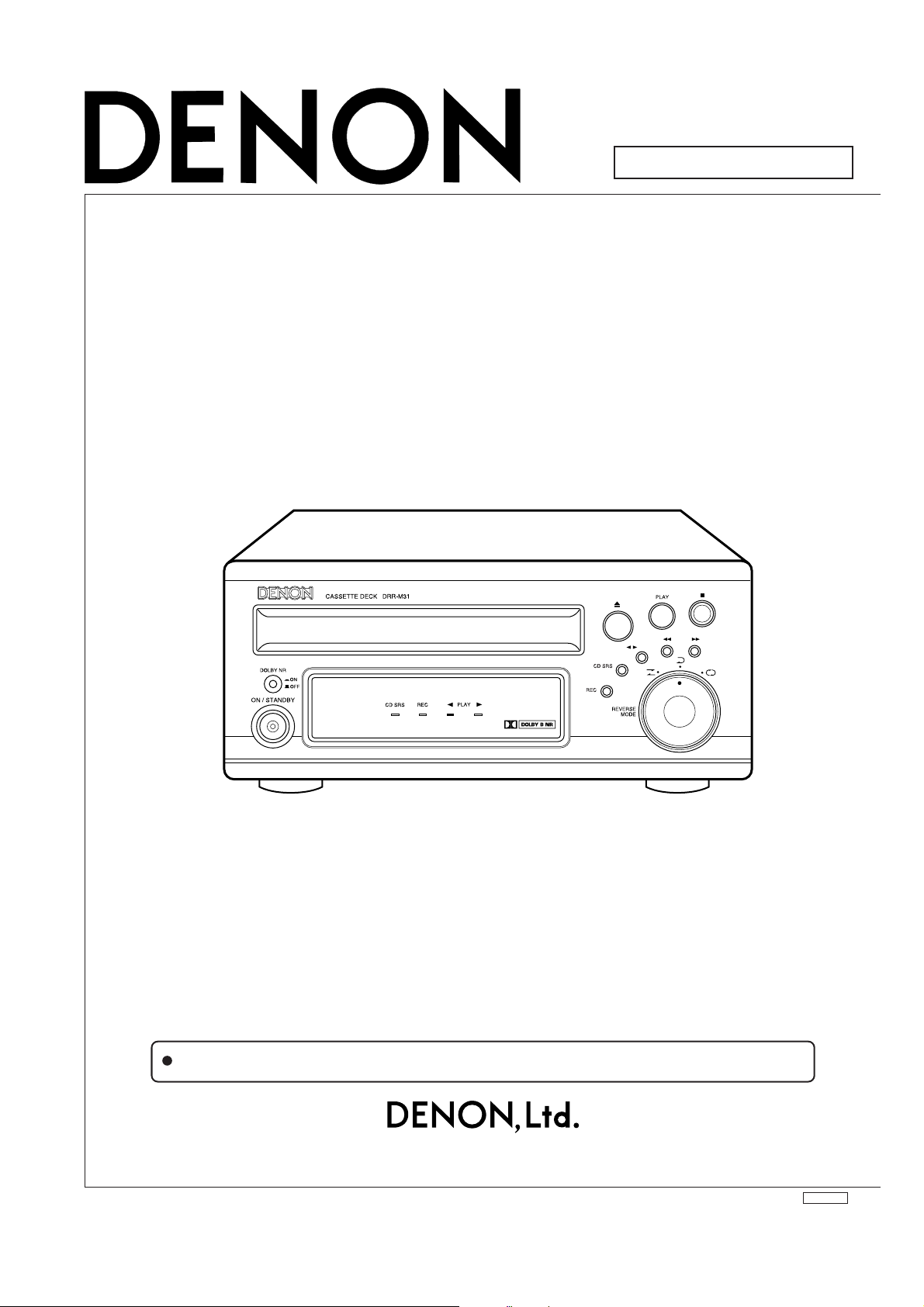
STEREO CASSETTE DECK
DRR-M31
Some illustrations using in this service manual are slightly different from the actual set.
16-11, YUSHIMA 3-CHOME, BUNKYOU-KU, TOKYO 113-0034 JAPAN
Telephone: 03 (3837) 5321
X0166V.02 DE/CDM 0302
Page 2

SAFETY PRECAUTIONS
The following check should be performed for the continued protection of the customer and service technician.
LEAKAGE CURRENT CHECK
Before returning the unit to the customer, make sure you make either (1) a leakage current check or (2) a line to chassis
resistance check. If the leakage current exceeds 0.5 milliamps, or if the resistance from chassis to either side of the
power cord is less than 460 kohms, the unit is defective.
2DRR-M31
2
Page 3
DISASSEMBLY
(Follow the procedure below in reverse order when reassembling)
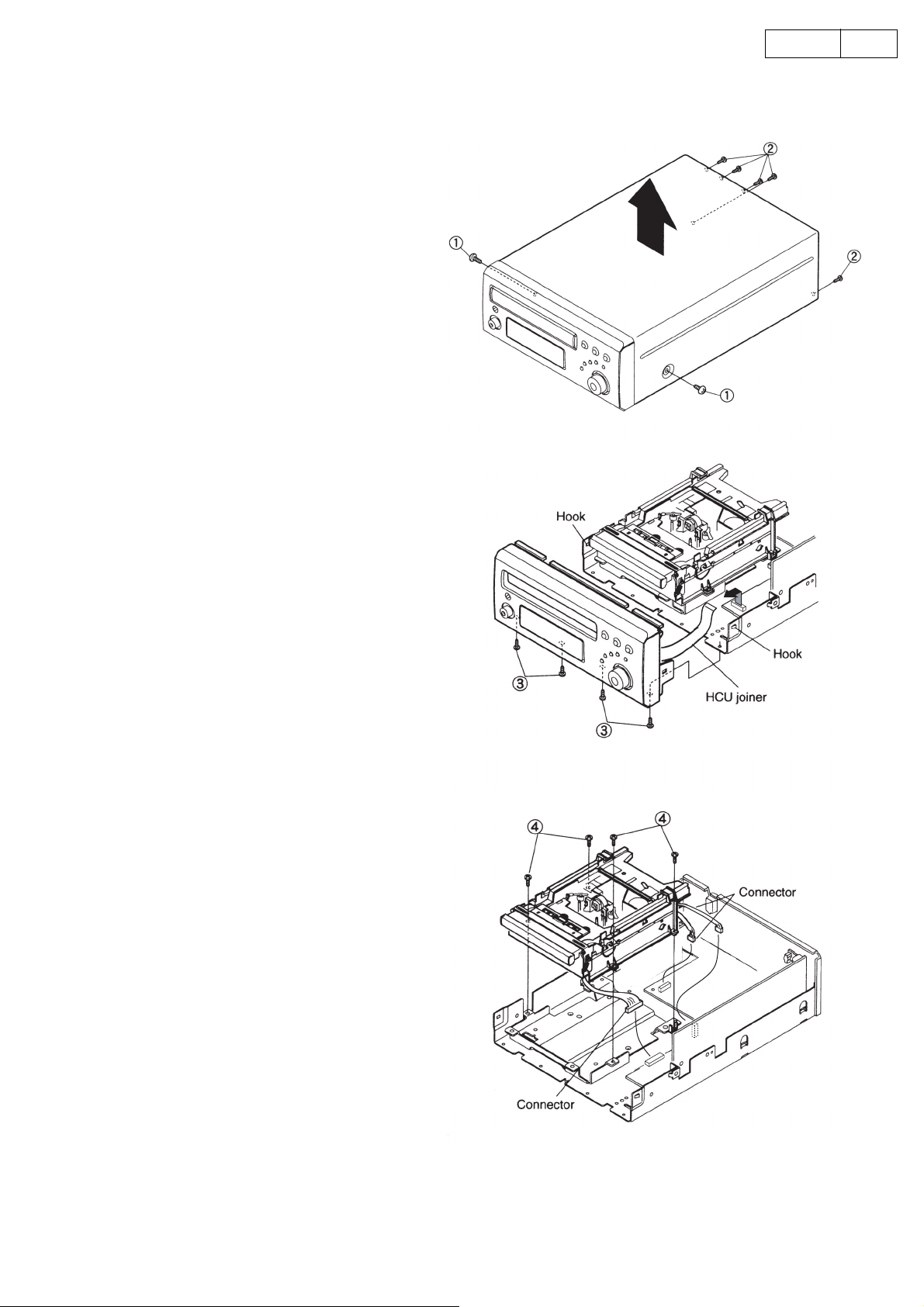
1. TOP COVER
(1) Remove 2 screws ① fixing from the both
sides.
(2) Remove 5 screws ② fixing to the Rear Plate,
then detach the Top Cover in the arrow direction .
2. FRONT PANEL
(1) Disconnect 1 HCU joiner coming from the
front P.W.B.
(2) Remove 4 screws ③ fixing the Front Panel at
the bottom.
(3) Whil releasing 2 hooks, detach the Front
Panel.
3DRR-M31
3. CASSETTE MECHA. ASS’Y
(1) Remove 4 screws ④ fixing the Cassette
Mecha. Ass’y.
(2) Disconnect 3 connectors, then detach the
Cassette Mecha. Ass’y.
3
Page 4
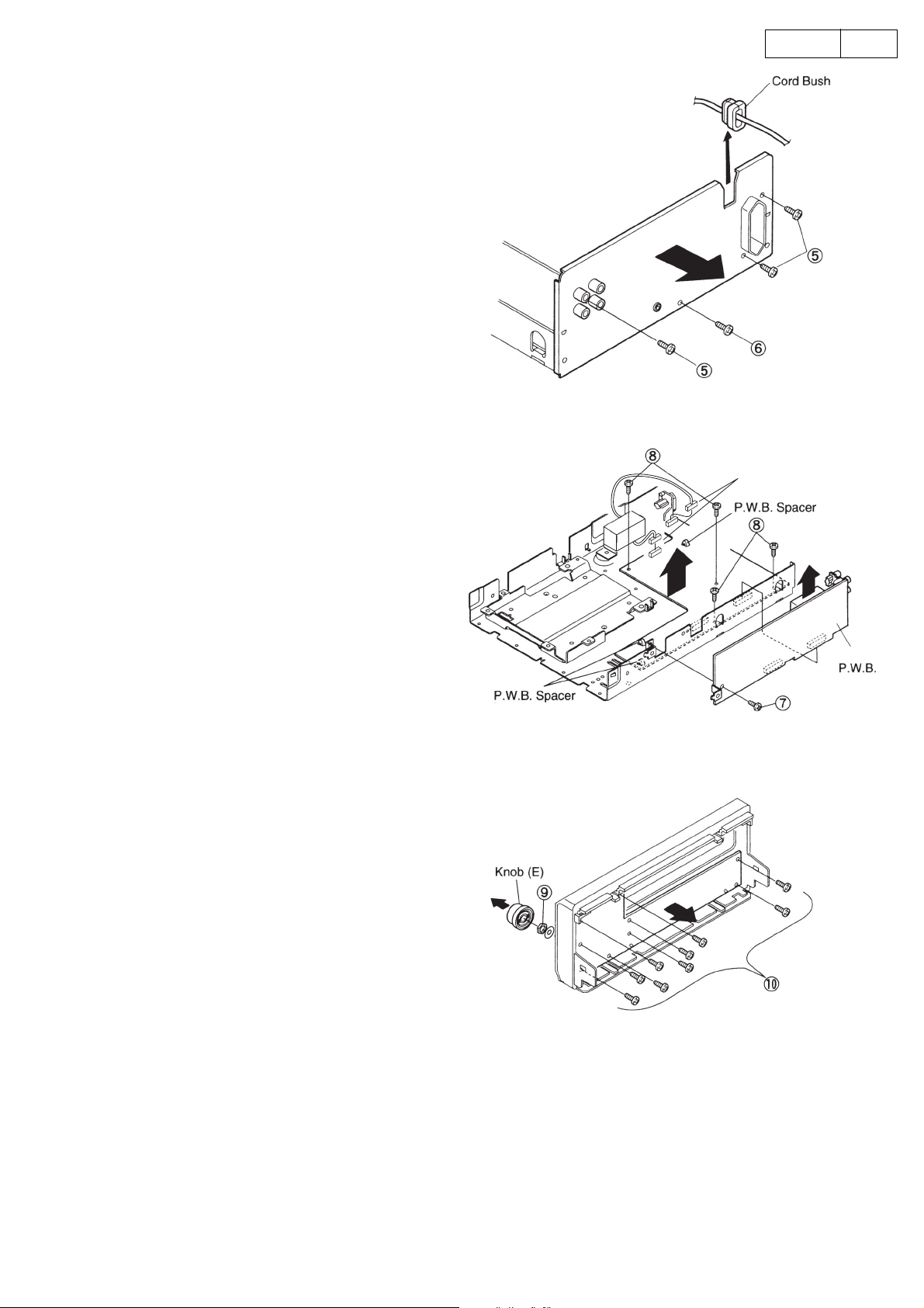
4. REAR PLATE
(1) Pull up the Power Cord together with the cord
bush to disengage from the Rear Plate.
(2) Remove 3 screws ⑤ fixing the 4P pin jack and
AC outlet respectively.
(3) Remove 1 screw ⑥ , and detach the Rear Plate.
5. MAIN P.W.B.
(1) Remove 1 screw ⑦ fixing the AMP P.W.B.
(2) Pull up the AMP P.W.B. as shown in the arrow
direction, and disconnect 2 connectors.
(3) Remove 4 screws ⑧ fixing the Main P.W.B.
(4) Release 3 pieces of P.W.B. spacers.
(5) Disconnect the connector from the Trans Unit.
(6) Take off the Main P.W.B.
4DRR-M31
Connector
6. DISPLAY P.W.B.
(1) Pull out the knob (E).
(2) Remove the nut and washer ⑨ for the rotary
switch.
(3) Remove 9 screws ⑩ .
(4) Take off the Display P.W.B.
AMP
4
Page 5
ADJUSTMENTS
6
ADJUSTMENTS
Adjusting and Checking the Mechanism Section
5DRR-M31
1. Replacement of the pinch roller
Before replacing the pinch roller, clean the tape contact
surface of the pinch roller and the tape contact surface of
the capstan shaft. After replacement, run a C-90 tape
without a pad and check for the presence of tape curl at
the tape guide portion of the head.
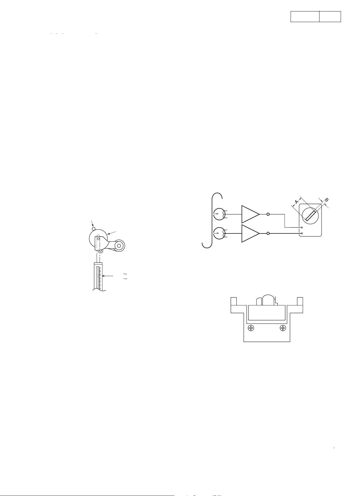
2. Checking the pinch roller pressure
Set to the playback condition and hook a bar-type spring
scale to the bracket above the center line of the pinch
roller. Pull the pinch roller away from the capstan shaft,
then allow the pinch roller to come into contact with the
capstan shaft and check that the reading of the bar-type
spring scale is between 2.45 N~3.92 N (250~400 g) when
the pinch roller starts to rotate or pull force indicates more
than 7.85 mN (80 g).
Replace the pinch roller when the value falls outside of
the specified range.
Capstan shaft
Pinch roller
4. Adjustment of the recording/playback head
Azimuth adjustment
Load side A of the A-BEX TCC-153 test tape facing
forward, and adjust.
(1) Play in the FWD direction and turn the azimuth
adjustment nut for the FWD side so that the
Lissajous’s figure becomes maximum at (A) and
minimum at (B).
(2) Play in the REV direction and turn the azimuth
adjustment nut for the REV side as adjusting the
FWD side method.
(3) Adjust (1) and (2) again.
(4) Apply screw lock to the adjustment locations.
PB Amp
LINE OUT
L
V
R
H
2.45 3.92N
(250
400g)
3. Replacement of the recording/playback
assembly
3-1 Removal of the head assembly
(1) Remove the 2 BRACKET-HEAD fastening screws.
(2) Remove one screw fixing P.W.B.
3-2 Mounting the recording/playback head assembly
Perform by following the steps of Section 3-1
Removal of the head assembly in reverse.
head
A-BEX TCC-153
REC/PB HEAD
A
FWD SIDE
B
REV SIDE
5. Checking the winding torque
Load a cassette type torque meter (Sony TW2111A at
the FWD side) and check that the reading of the torque
meter during playback is
294 to 686 mN-cm (30 to 70 g-cm) at the center value.
5
Page 6
6. Checking the back tension torque at the time
r
of recording and playback
Load a cassette type torque meter (Sony TW2111A at
the FWD side, Sony TW2121A at the REV side) and check
that the reading of the torque meter during playback is
9.8~58.5 mN-cm (1~6 g-cm) and that there is no
unevenness.
7. Checking the FF and REW torque
Load a cassette type torque meter (Sony TW2231) and
check that the value indicated by the torque meter for
winding and rewinding is between 686 mN-cm~
(70~150 g-cm).
1.47 N-cm
Adjusting and Checking the Electrical Section
6DRR-M31
8. Checking the FF and REW time
Load a Type 1 tape (UD-1), and check that the time for
FF and REW is less than 120 seconds. When outside of
the specified range, check Steps 5 and 6.
9. Checking the erroneous erasure prevention,
and the metal and chrome switch operations
Check that detection lever is operating the switch properly
depending upon the presence or absence of a hole.
Measuring instruments needed for the adjustments
(1) Low frequency oscillator
(2) Variable resistance attenuator
(3) Electronic voltmeter
(4) Oscilloscope
(5) Frequency counter
(6) Adjustment screwdriver
(7) Test tapes
MTT-111, MTT-114N, MTT-150, Type1 tape (UD-1)
(8) Mirror cassette for the transport (A-BEX TCC-902)
Adjustment precaution
(1) Before adjustments, use gauze or a swab moistened
with alcohol to wipe the surface of the heads, the
capstan shaft, and the pinch roller.
(2) Demagnetize the record/playback head and the
erase head with a head eraser.
(3) Completely demagnetize the driver to be used for
the adjustments.
(4) Unless otherwise specified, set the various operation
controls as indicated below.
Dolby NR switch: Off
1. Tape transport check
Load the mirror cassette for the transport, and illuminate
the area around the fixed guide of the record/playback
head with a lamp and observe.
Check that the tape edge is not hitting the tape guide
portion.
Note that the tape transport is the greatest factor affecting
the performance of the cassette deck. Never move the
inspection locations without good reason.
For information about replacement and adjustment of the
record/playback head, see the section “Adjustment and
checking of the mechanism”.
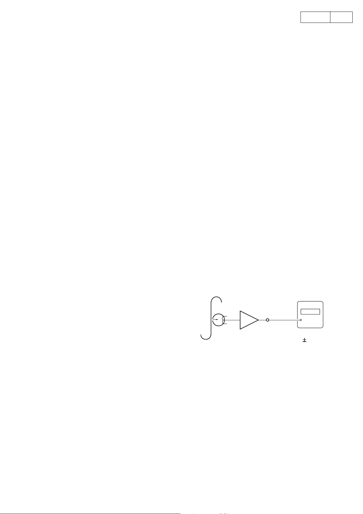
2. Tape speed check and adjustment
(1) Connect the frequency counter to the LINE OUT pin
and load the test tape (MTT-111).
(2) Playback FWD side of the test tape. At about halfway
through the tape, where the tape transport is stable,
confirm that the frequency counter will have a
reading within the range of 3,000 Hz ±10 Hz.
(3) Check REV side also that the counter reading
indicates within 2955~3045Hz.
Note: Adjust within 30 seconds, after pre-heating
(Play) of 20min, or more.
Frequency counte
PB Amp
LINE OUT
MTT-111
3000
3000Hz
10Hz
6
Page 7
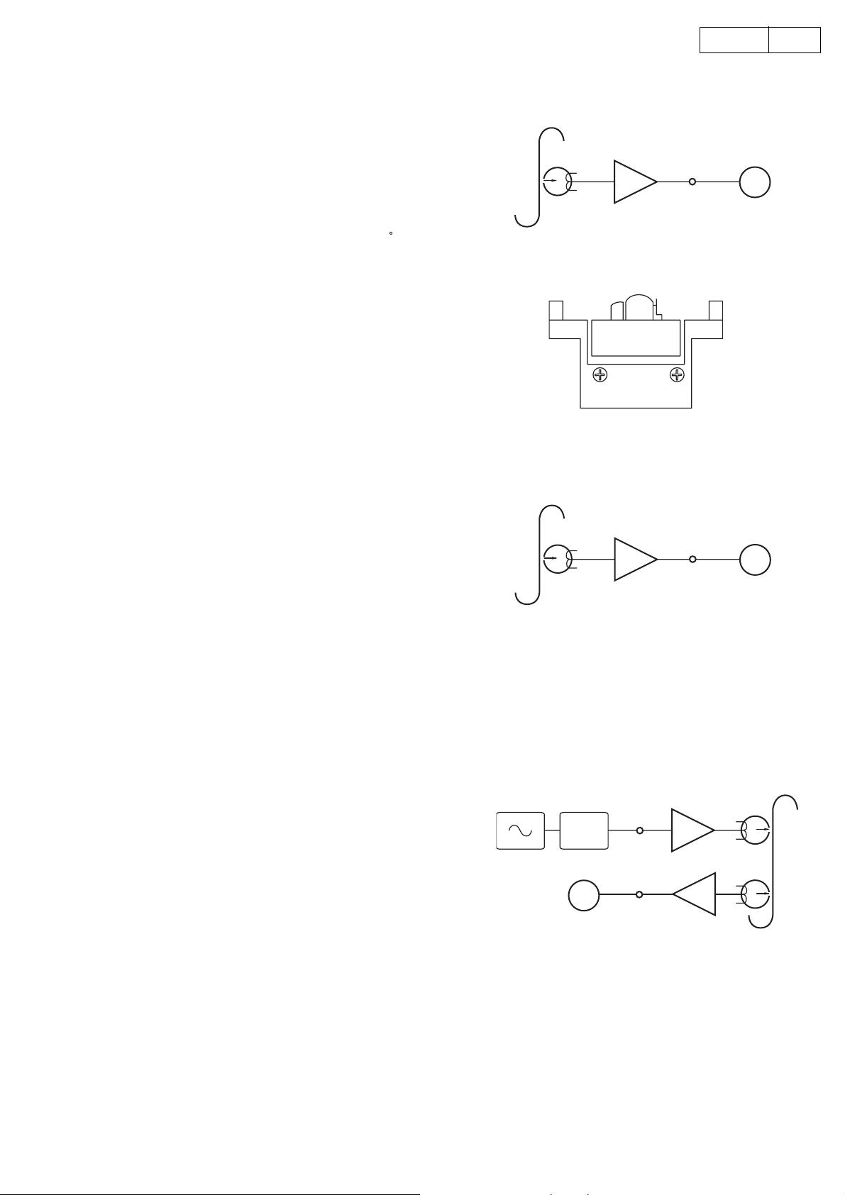
3. Azimuth Adjustment
)
(1) Connect an electronic voltmeter to the Line Out
terminal, and set Test tape MTT-114N into the Unit.
(2) Playback FWD side,and adjust the azimuth screw A
so as to get maximum indication on the voltmeter,
then make the same adjustment with the screw B for
REV side.
(3) Readjust if the output level difference exceeds 2dB
after adjustment, and also confirm that the phase
difference in the both channels is within ±45
Note: In order to prevent the backlash of the azimuth
screw, end in the clockwise rotation.
7DRR-M31
PB Amp
LINE OUT
.
MTT-114N
V. V
4. PB Output Level Adjustment
(1) Connect an electronic voltmeter to the Line Out
terminal, and set Test tape MTT-150 into the Unit.
(2) Playback FWD side, and adjust the VR301 (Lch) and
VR302 (Rch) so that the voltmeter indicates 400mV
±0.5dB.
5. REC Level Adjustment
(1) Set Test Tape (Type1 tape: UD-1) into the Unit,and
record 400mV −10dB 400Hz signal at JK301 input
level on the tape.
(2) Playback the recorded signal, and adjust VR304 (Lch)
and VR303 (Rch) so that the voltmeter indicates
−10dB ±0.5dB at JK301 output level.
MTT-150
400Hz
A
FWD SIDE
ATT
V. V
B
REV SIDE
PB Amp
LINE OUT
V. V
REC Amp
LINE IN
LINE OUT
PB Amp
Type 1 tape(UD-1
7
Page 8
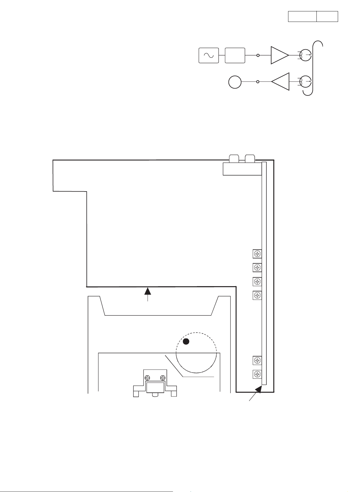
6. Bias Current Adjustment
)
(1) Set Test Tape (Type1 tape: UD-1) into the Unit, and
record 400mV -23dB 1.25kHz/12.5kHz signal at JK301
level on the tape.
(2) Playback the recorded signal, and adjust VR306 (Lch)
and VR305 (Rch) so that the level difference between
both frequencies becomes within the range of
+2dB ~ -0.5dB on the voltmeter.
ADJUSTMENT POINTS
ATT
1.25kHz
12.5kHz
V. V
LINE IN LINE OUT
JK301
8DRR-M31
REC Amp
LINE IN
LINE OUT
PB Amp
Type 1 tape(UD-1
(Deck Mecha.)
MAIN P.W.B
Azimuth Adjust
R/P Level Adjust
PB GAIN Adjust
Tape Speed Adjust
Rch
VR304
Lch
VR303
Lch
VR301
Rch
VR302
Lch
VR306
Rch
VR305
AMP P.W.B
8
Page 9
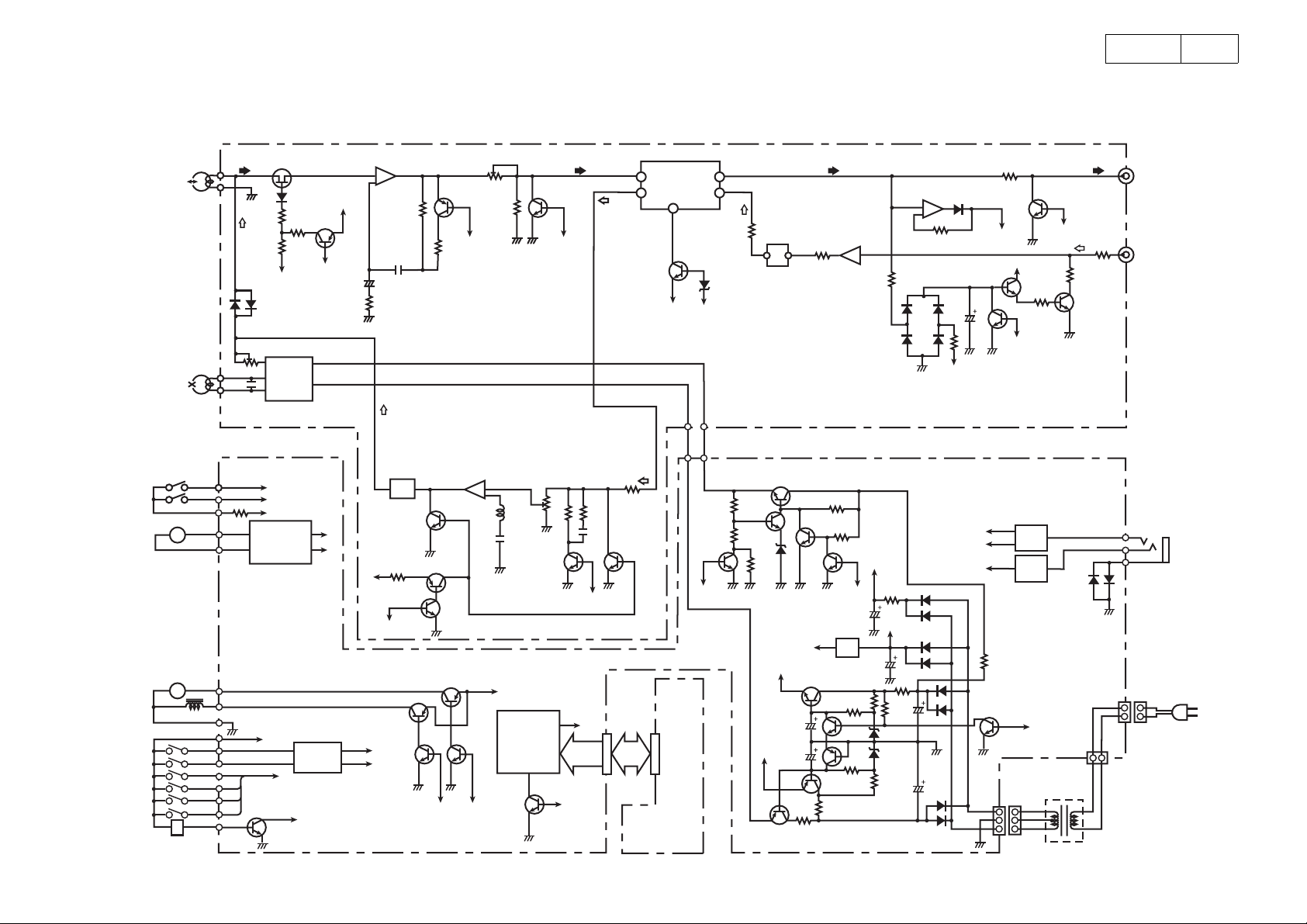
BLOCK DIAGRAM
DRR-M31
9
CLOSE
OPEN
LOADING
MOTOR
CAPSTAN
MOTOR
SOL
R/P HEAD
E. HEAD
HALL IC
M
M
CrO2 SW
NOR SW
F. REC
R. REC
HALF
MODE
TU201,202
BIAS ADJ.
VR201,202
μCOM. CLOSE
μCOM. OPEN
+5V
IC302
MOTOR
DRIVE
+5V
μCOM
R/P
SWITCHING
-7V
L203
TR204
TR205
BIAS OSC
μCOM
TR506
TR507
μCOM. REEL PULSE
μCOM
R/P
+B
-7V
+7V
TR203
PLAYBACK
AMP
IC201
BIAS TRAP
+5V
μCOM
R. MUTE
TR501
NOR
CrO
2
TR307
TR308
SOLENOID
μCOM
PLAY BACK LEVEL ADJ.
VR203,204
TR206,207
NOR
REC AMP REC LEVEL ADJ.
IC301
TR303
TR304
TR502
TR504 TR505
MOTOR
μCOM
+12V
RESET
VR301
VR302
IC501
μCOM
TR208,209
μCOM
R/P
TR510
TR305,306
NOR
+5V
P. OFF
PB IN
REC OUT
TR301,302
IC203
DOLBY IC
TR201
-7V
KEY
& LED
DISTLAY PWB
PB OUT ( Lch )
REC IN
D.RP
TR509 ( μCOM )
TR312
2
CrO
R/P PWB
TR313
-7V
TR328
MPX
FILTER
L201,202
TR314
+7V
TR327
TR315
+5V
TR326
TR324
IC205
TR316
μCOM
BIAS
IC304
TR325
IC204
LEVEL DETECT AMP ( A/D )
AUTO LEVEL CONTROL
P. OFF
+12V
DOLBY IC
PB OUT ( Rch )
MAIN PWB
μCOM. SO
μCOM. SI
μCOM. SCK
μCOM
A/D INPUT
TR211
μCOM
R. MUTE
TR323
TP215,216
TR317
( LINE MUTE OUT )
+7V
TR212
P. ON
LD405
(
Green
T101
POWER TRANS
LINE OUT
LINE MUTE
LINE IN
TR213,214
CD SYNCHRO
JK301
AC PLUG
(
9
Page 10
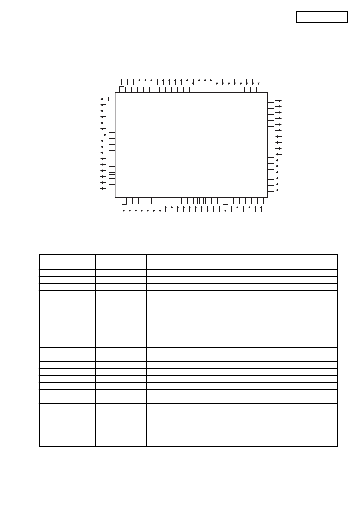
SEMICONDUCTORS
IC's
µ µ
µPD78044FGF (IC203)
µ µ
P113 / FIP21
P112 / FIP20
P111 / FIP19
P110 / FIP18
P107 / FIP17
P106 / FIP16
VLOAD
P105 / FIP15
P104 / FIP14
P103 / FIP13
P102 / FIP12
P101 / FIP11
P100 / FIP10
P97 / FIP9
P96 / FIP8
P95 / FIP7
10DRR-M31
P114 / FIP22
P115 / FIP23
P116 / FIP24
P117 / FIP25
P120 / FIP26
P121 / FIP27
P122 / FIP28
P123 / FIP29
P124 / FIP30
P125 / FIP31
P126 / FIP32
P127 / FIP33
VDD
P70
P71
P72
IC (VPP)
P00 / INTP0
P01 / INTP1
P02 / INTP2
P03 / INTP3
P30 / TO0
P31 / TO1
P32 / TO2
6061
62
64
63
65
66
67
68
69
70
71
72
73
74
75
76
77
78
79
80
57
59
58
55
56
54
53
5152
TOP VIEW
46
4748
49
50
41
42
P33 / TI1
40
39
P34 / TI2
P35 / PCL
38
P36 / BUZ
37
36
P37
X2
35
X1
34
VSS
33
32
XT2
31
P04 / XT1
30
AVREF
29
AVDD
28
P10 / ANI0
27
P11 / ANI1
26
P12 / ANI2
25
P13 / ANI3
43
45
44
3
2
P94 / FIP6
P93 / FIP5
P92 / FIP4
4567
P91 / FIP3
P90 / FIP2
P81 / FIP1
P80 / FIP0
1
11
9
8
10
VDD
P26 / SO0
P27 / SCK0
P25 / SI0
12 13
P24 / BUSY
14
P23 / STB
P22 / SCK1
15 16
P21 / SO1
17 18 19 20
P74
RESET
P20 / SI1
P73
21
AVSS
22
23 24
P17 / ANI7
P16 / ANI6
P15 / ANI5
P14 / ANI4
PPPPPD78044FGF Terminal Function
Pin
No.
10 P26/SO0
11 P26/SI0 REC REV I Hi-z Deck mecha REC REV SW input
12 P24/BUSY PACK I Hi-z Deck mecha PACK SW input
13 P23/STB
14 P22/SCK1 SERCLK I Hi-z DENON BUS communication clock signal (Edge intervention)
15 P21/SO1 SEROUT O Hi-z DENON BUS communication output data signal
16 P20/SI1 SER IN I Hi-z DENON BUS communication input data signal
17 RESET RESET I Hi-z Reset input
18 P74 R MUTE
19 P73 HEADSW O Hi-z Head switching control signal (L: PB only)
20 AVSS AVSS O
21 P17/AN17 RVSMOD I Hi-z Reverse mode input signal
22 P16/AN16 KEYIN 2 I Hi-z Tact operating button input No.2
23 P15/AN15 KEYIN 1 I Hi-z Tact operating button input No.1
24 P14/AN14 KEYIN 1 I Hi-z Tact operating button input No.0
25 AN13 MSREF I Hi-z Music serch detection reference voltage
Port Name Symbol I/O Ini Function
1 P94/FIP6 MTCONT2 O Hi-z Reel, Loader motor control
2 P93/FIP5 MTCONT1 O Hi-z Reel, Loader motor control
3 P92/FIP4 LED FP O Hi-z LED output FWD, PLAY ind. (H: light )
4 P91/FIP3 LED RP O Hi-z LED output REV, PLAY ind. (H: light )
5 P90/FIP2 LED REC O Hi-z LED output REC ind. (H: light )
6 P81/FIP1 LED SRS O Hi-z LED output CD SRS ind. (H: light )
7 P80/FIP0 LED PWR O Hi-z LED output POWER. (H: light )
8VDD VDD
+5V Power
9 P27/SCK0 REC FWD I Hi-z Deck mecha REC FWD SW input
I Hi-z Not used (connect to GND)
I Hi-z Not used (connect to GND)
Hi-z REC mute control signal (H: mute)
Analog GND
10
Page 11

11DRR-M31
Pin
No.
26 P12/ANI2 TEST I Hi-z Board check mode input terminal
27 P11/ANI1 AD-L I Hi-z Audio signal L-ch
28 P10/ANI0 AD-R I Hi-z Audio signal R-ch
29 AVDD AVDD
30 AVREF AVREF
31 P04/XT1
32 XT2 XT2 O
33 VSS VSS
34 X1 X1 I
35 X2 X2 O
36 P37
37 P36/BUZ
38 P35/PCL
39 P34/TI2 SOL O Hi-z Solenoid control signal
40 P33/TI1 MOT O Hi-z Motor control signal
41 P32/TO2 MODESW I Hi-z Deck mecka mode SW input signal (H: stop)
42 P31/TO1 LOADOUT I Hi-z Loader open input signal
43 P30/TO0 LOADIN I Hi-z Loader close input signal
44 P03/INTP3 STANBY I Hi-z Power shut off detection signal (H: normal,L: shut off)
45 P02/INTP2 REEL I Hi-z Supply reel pulse input signal
46 P01/INTP1
47 P00/INTP0 SERINT I Hi-z DENON BUS communicate intervention signal
48 IC IC
49 P72
50 P71
51 P70
52 VDD VDD
53 P127/FIP33 L MUTE O Hi-z Line mute control signal (L: mute)
54 P126/FIP32 DOLBY O Hi-z Not used: DOLBY switching signal (H: off)
55 P125/FIP31 DOLB/C O Hi-z Not used: DOLBY B/C switching signal (H: B)
56 P124/FIP30 DOLR/P O Hi-z DOLBY REC /PB switching signal (L: PB)
57 P123/FIP29 MPXFIL O Hi-z Not used : MPX filter control signal
58 P122/FIP28
59 P121/FIP27 BIAS O Hi-z Bias control signal (H: OSC)
60 P120/FIP26
61 P117/FIP25
62 P116/FIP24
63 P115/FIP23
64 P114/FIP22
65 P113/FIP21
66 P112/FIP20
67 P111/FIP19
68 P110/FIP18
69 P107/FIP17
70 P106/FIP16
71 VLOAD VLOAD
72 P105/FIP15
73 P104/FIP14
74 P103/FIP13
75 P102/FIP12
76 P101/FIP11
77 P100/FIP10
78 P97/FIP9
79 P96/FIP8
80 P95/FIP7
Port Name Symbol I/O Ini Function
Analog power (+5v)
Analog refernce voltage
Not used: open
GND
Main systemclock input
Main systemclock output
Internal connection terminal,connect to Vss
Hi-z5V power
connect to GND
LED-PR
LED-PG
I Hi-z Not used: either pull up/down
O Hi-z Not used open
O Hi-z Not used open
O Hi-z Not used open
I Hi-z Not used
O Hi-z Not used: open
O Hi-z Not used: open
O Hi-z Not used: open
O Hi-z Not used: open
O Hi-z Not used: open
O Hi-z Not used: open
O Hi-z Not used: open
O Hi-z Not used: open
O Hi-z Not used: open
O Hi-z Not used: open
O Hi-z Not used: open
O Hi-z Not used: open
O Hi-z Not used: open
O Hi-z Not used: open
O Hi-z Not used: open
O Hi-z connect to GND
O Hi-z connect to GND
O Hi-z connect to GND
O Hi-z connect to GND
O Hi-z connect to GND
O Hi-z connect to GND
O Hi-z connect to GND
OHi-zPOWER OFF:H
OHi-zPOWER ON:H
11
Page 12

HA12136AF (IC302)
12DRR-M31
REC IN
16 15
BIAS
REC IN
PB IN
GND
14 13 12 11 10 9
SW
SW
321
CC
V
PB IN
BIAS
REF
V
BUF
AMP
BUF
AMP
REC/PB
NR ON/OFF
PB OUT
PB OUT
SIDE
CHAIN
SIDE
CHAIN
DET
DET
REC OUT
87654
REC OUT
TRANSISTOR
DTA114TK
DTA124EK
DTC114TK
DTC124EK
DTC143EK
DTC323TK
FRONT VIEW
B
E
DTA Series DTC Series
R1
IN
(B)
R2
C
DTA114TK 10kohm
DTA124EK
R1 R2
22kohm 22kohm
OUT (C)
GND (E)
IN
(B)
DTC114TK
DTC124EK
DTC143TK
DTC323TK
R1
R2
R1
10kohm
22kohm
4.7kohm
2.2kohm
OUT (C)
GND (E)
R2
22kohm
4.7kohm
12
Page 13

PRINTED WIRING BOARDS
1U-3501-1 MAIN UNIT / 1U-3501-2 AMP UNIT / 1U-3501-3 DISP UNIT
DRR-M31
13
13
COMPONENT SIDE
Page 14

DRR-M31
14
14
FOIL SIDE
Page 15

NOTE FOR PARTS LIST
l Part indicated with the mark "" are not always in stock and possibly to take a long period of time for supplying, or in
some case supplying of part may be refused.
l When ordering of part, clearly indicate "1" and "I" (i) to avoid mis-supplying.
l Ordering part without stating its part number can not be supplied.
l Part indicated with the mark " " is not illustrated in the exploded view.
l Not including Carbon Film ±5%, 1/4W Type in the P.W.Board parts list. (Refer to the Schematic Diagram for those parts.)
WARNING:
Parts marked with this symbol
Use ONLY replacement parts recommended by the manufacturer.
have critical characteristics.
15DRR-M31
ll
Resistors
l
ll
Ex.: RN 14K 2E 182 G FR
Type Shape Power Resist- Allowable Others
and per- ance error
formance
t
RD : Carbon 2B : 1/8W F : ±1% P : Pulse-resistant type
RC : Composition 2E : 1/4W G : ±2% NL : Low noise type
RS : Metal oxide film 2H : 1/2W J : ±5% NB : Non-burning type
RW : Winding 3A : 1W K : ±10% FR : Fuse-resistor
RN : Metal film 3D : 2W M : ±20% F : Lead wire forming
RK : Metal mixture 3F : 3W
Resistance
1 8 2 ⇒ 1800 ohm = 1.8 kohm
s
s
• Units: ohm
1 R 2 ⇒ 1.2 ohm
s
s
• Units: ohm
t
3H : 5W
Indicates number of zeros after effective number.
2-digit effective number.
1-digit effective number.
2-digit effective number, decimal point indicated by R.
t
t
ll
Capacitors
l
ll
Ex.: CE 04W 1H 2R2 M BP
Type Shape Dielectric Capacity Allowable Others
and per- strength error
formance
t
CE : Aluminum foil 0J : 6.3V F : ±1% HS : High stability type
electrolytic
CA : Aluminum solid 1A : 10V G : ±2% BP : Non-polar type
electrolytic
CS : Tantalum electrolytic 1C : 16V J : ±5% HR: Ripple-resistant type
CQ : Film 1E : 25V K : ±10% DL : For change and discharge
CK : Ceramic 1V : 35V M : ±20% HF : For assuring high
CC : Ceramic 1H : 50V Z : +80% U : UL par t
CP : Oil 2A : 100V –20% C : CSA part
CM : Mica 2B : 125V P : +100% W : UL-CSA type
CF : Metallized 2C : 160V –0% F : Lead wire forming
CH : Metallized 2D : 200V C : ±0.25pF
Capacity (electrolyte only)
2 2 2 ⇒ 2200µF
s
s
• Units: µF.
2 R 2 ⇒ 2.2µF
s
s
• Units: µF.
Capacity (except electrolyte)
2 2 2 ⇒ 2200pF=0.0022µF
s
s
(More than 2) Indicates number of zeros after effective number.
• Units: pF.
2 2 1 ⇒ 220pF
s
s
(0 or 1) Indicates number of zeros after effective number.
• Units: pF.
• When the dielectric strength is indicated in AC, "AC" is included after the dieelectric
strength value.
t
2E : 250V D : ±0.5pF
2H : 500V = : Others
2J : 630V
Indicates number of zeros after effective number.
2-digit effective number.
1-digit effective number.
2-digit effective number, decimal point indicated by R.
2-digit effective number.
2-digit effective number.
t
t
requency
15
Page 16

PARTS LIST OF P.W.B. UNIT ASS'Y
1U-3501 DECK UNIT ASS'Y
Ref. No. Part No. Part Name Remarks New
SEMICONDUCTORS GROUP
IC201 263 0402 005 BA6209
IC202 268 0073 905 ICP-N15T
IC203 262 3178 003 UPD78044FGF-212-3B9 *
IC204 263 0792 003 NJM78M06FA(S)
IC301 263 0896 909 NJM2068MD-TE1
IC302 263 1171 908 HA12136AF
IC303-305 263 0615 902 BA15218F-DXE2
TR103 269 0088 906 DTC114TKT96
TR201-204 269 0102 905 DTC124EKT146
TR205 269 0119 901 DTA124EKT96(TAPE)
TR206 269 0102 905 DTC124EKT146
TR207,208 272 0163 005 HIT5610
TR209-213 269 0102 905 DTC124EKT146
TR214 273 0384 900 2SC2412KT96(S)
TR215 273 0426 907 2SC2412KLNT146
TR216 269 0102 905 DTC124EKT146
TR217 272 0164 004 KTD2058Y
TR218,219 273 0384 900 2SC2412KT96(S)
TR220 269 0102 905 DTC124EKT146
TR221 269 0119 901 DTA124EKT96(TAPE)
TR222 269 0102 905 DTC124EKT146
TR223 274 0201 002 HIT5609
TR224 269 0102 905 DTC124EKT146
TR225 273 0384 900 2SC2412KT96(S)
TR226 271 0309 905 2SA1037AKT146S
TR227,228 274 0202 001 KTB1366Y
TR229 271 0309 905 2SA1037AKT146S
TR230 273 0384 900 2SC2412KT96(S)
TR231 271 0309 905 2SA1037AKT146S
TR232 273 0384 900 2SC2412KT96(S)
TR301,302 275 0042 905 2SK373(Y)TPE2
TR303,304 269 0086 908 DTA114TKT96
TR305,306 269 0048 904 DTC143EK-T96
TR307,308 269 0102 905 DTC124EKT146
TR309,310 273 0426 907 2SC2412KLNT146
TR311-314 269 0066 902 DTC323TKT96
TR315,316 273 0466 909 2SC2120
TR317,318 269 0066 902 DTC323TKT96
TR319,320 269 0088 906 DTC114TKT96
TR321,322 269 0066 902 DTC323TKT96
TR323 269 0102 905 DTC124EKT146
TR324,325 269 0119 901 DTA124EKT96(TAPE)
TR326 273 0426 907 2SC2412KLNT146
16DRR-M31
D201-213 276 0375 905 1N4148T77 (TAPE)
D214,215 276 0772 003 1N4004
D216,217 276 0375 905 1N4148T77 (TAPE)
D218-223 276 0772 003 1N4004
D224,225 276 0375 905 1N4148T77 (TAPE)
D226 276 0772 003 1N4004
D227 276 0375 905 1N4148T77 (TAPE)
D301-314 276 0375 905 1N4148T77 (TAPE)
ZD201 276 0760 989 MTZJ7.5B T77
ZD202 276 0636 903 MTZJ8.2BT77
16
Page 17

Ref. No. Part No. Part Name Remarks New
ZD203 276 0760 905 MTZJ3.6B T77
ZD204 276 0636 903 MTZJ8.2BT77
ZD206 276 0760 905 MTZJ3.6B T77
ZD207 276 0760 918 MTZJ3.9B T77
ZD208,209 276 0760 963 MTZJ6.2B T77
ZD210,211 276 0636 903 MTZJ8.2BT77
ZD212 276 0760 950 MTZJ5.6B T77
ZD301 276 0760 963 MTZJ6.2B T77
ZD302 276 0636 903 MTZJ8.2BT77
LD101,102 393 9616 009 SLR-136B-81
LD103,104 393 9617 008 SLR-236B-81
LD105 393 9618 007 SLR-9336DS-91
RESISTORS GROUP
R101 247 2005 961 RM73B--181JT
R106-108 247 2006 986 RM73B--561JT
R109,110 247 2006 915 RM73B--271JT
R111,112 247 2008 926 RM73B--222JT
R113-116 247 2007 943 RM73B--102JT
R117 247 2005 961 RM73B--181JT
R118 247 2005 945 RM73B--151JT
R119 247 2005 961 RM73B--181JT
R120 247 2006 928 RM73B--301JT
R121 247 2005 945 RM73B--151JT
R122 247 2005 961 RM73B--181JT
R123 247 2006 928 RM73B--301JT
R127 247 2005 987 RM73B--221JT
R201 247 2009 983 RM73B--103JT
R202 247 2009 909 RM73B--472JT (1608)
R203,204 247 2009 983 RM73B--103JT
R205 247 2007 943 RM73B--102JT
R206,207 244 2051 945 RS14B3A010JNBST(S)
R208 247 2007 943 RM73B--102JT
R209,210 247 2011 942 RM73B--473JT
R211-213 247 2007 943 RM73B--102JT
R214-216 247 2011 942 RM73B--473JT
R218 247 2007 943 RM73B--102JT
R219 247 2012 925 RM73B--104JT
R220 247 2006 902 RM73B--331JT (1608)
R221-223 247 2007 943 RM73B--102JT
R224,225 247 2011 942 RM73B--473JT
R226 247 2009 909 RM73B--472JT (1608)
R227 247 2009 983 RM73B--103JT
R228 247 2012 925 RM73B--104JT
R229 247 2009 983 RM73B--103JT
R230 247 2012 925 RM73B--104JT
R231 247 2008 926 RM73B--222JT
R232 247 2009 925 RM73B--562JT
R235 247 2011 942 RM73B--473JT
R237 247 2011 942 RM73B--473JT
R238,239 247 2010 969 RM73B--223JT
R241 247 2009 983 RM73B--103JT
R242,243 247 2009 909 RM73B--472JT (1608)
R244 247 2009 925 RM73B--562JT
R245 247 2010 969 RM73B--223JT
R246 247 2005 987 RM73B--221JT
R247 244 2051 974 RS14B3A102JNBST(S)
17DRR-M31
17
Page 18

Ref. No. Part No. Part Name Remarks New
R248 241 2313 985 RD14B2E4R7JFRST
R249 244 2051 974 RS14B3A102JNBST(S)
R250 247 2005 987 RM73B--221JT
R251,252 241 2313 985 RD14B2E4R7JFRST
R253 247 2007 943 RM73B--102JT
R254 241 2379 987 RD14B2E102JNBST
R255,256 247 2007 943 RM73B--102JT
R257 247 2005 903 RM73B--101JT
R258,259 247 2010 969 RM73B--223JT
R260,261 247 2009 983 RM73B--103JT
R262 247 2011 942 RM73B--473JT
R263-265 247 2009 983 RM73B--103JT
R266 247 2005 987 RM73B--221JT
R267 247 2018 903 RM73B--0R0KT
R268 247 2009 983 RM73B--103JT
R269 247 2012 925 RM73B--104JT
R270 247 2011 942 RM73B--473JT
R271 247 2018 903 RM73B--0R0KT
R272 247 2010 969 RM73B--223JT
R273 247 2008 926 RM73B--222JT
R274 241 2313 985 RD14B2E4R7JFRST
R275 247 2009 983 RM73B--103JT
R276 241 2381 946 RD14B2E472JNBST
R277 241 2379 987 RD14B2E102JNBST
R278 247 2009 938 RM73B--622JT
R279 247 2010 901 RM73B--123JT
R281 247 2009 909 RM73B--472JT (1608)
R282 247 2009 925 RM73B--562JT
R283,284 247 2008 968 RM73B--332JT
R301,302 247 2015 948 RM73B--225KT
R303 247 2009 983 RM73B--103JT
R304 247 2011 942 RM73B--473JT
R305 247 2005 903 RM73B--101JT
R306 247 2006 944 RM73B--391JT
R307 247 2013 979 RM73B--434JT
R308 247 2010 998 RM73B--303JT
R309 247 2010 972 RM73B--243JT
R310,311 247 2015 948 RM73B--225KT
R312 247 2012 925 RM73B--104JT
R313 247 2011 942 RM73B--473JT
R314 247 2006 944 RM73B--391JT
R315 247 2005 903 RM73B--101JT
R316 247 2009 983 RM73B--103JT
R317 247 2010 972 RM73B--243JT
R318 247 2010 998 RM73B--303JT
R319 247 2009 909 RM73B--472JT (1608)
R320 247 2013 979 RM73B--434JT
R321 247 2006 902 RM73B--331JT (1608)
R322,323 247 2010 969 RM73B--223JT
R324 247 2008 926 RM73B--222JT
R325 247 2006 902 RM73B--331JT (1608)
R326,327 247 2009 983 RM73B--103JT
R328 247 2010 943 RM73B--183JT
R329-331 247 2010 956 RM73B--203JT
R332,333 247 2011 984 RM73B--683JT
R334-336 247 2010 985 RM73B--273JT
R337 247 2005 903 RM73B--101JT
R338 247 2010 985 RM73B--273JT
R339 247 2005 903 RM73B--101JT
R340,341 247 2014 965 RM73B--105JT
R342 247 2018 903 RM73B--0R0KT
18DRR-M31
18
Page 19

Ref. No. Part No. Part Name Remarks New
R343 247 2008 984 RM73B--392JT
R345 247 2008 984 RM73B--392JT
R346,347 247 2008 942 RM73B--272JT
R348,349 247 2007 943 RM73B--102JT
R350 247 2010 914 RM73B--133JT
R351 247 2007 969 RM73B--122JT
R352 247 2010 914 RM73B--133JT
R353 247 2007 969 RM73B--122JT
R354 247 2009 983 RM73B--103JT
R355,356 247 2009 909 RM73B--472JT (1608)
R357,358 247 2006 944 RM73B--391JT
R359-362 247 2011 926 RM73B--393JT
R363,364 247 2010 985 RM73B--273JT
R365 247 2006 960 RM73B--471JT
R366 247 2007 972 RM73B--132JT
R367 247 2008 913 RM73B--202JT
R368,369 247 2009 970 RM73B--912JT
R370 247 2006 960 RM73B--471JT
R371 247 2007 972 RM73B--132JT
R372 247 2008 913 RM73B--202JT
R373,374 247 2011 942 RM73B--473JT
R375 247 2018 903 RM73B--0R0KT
R376,377 247 2009 954 RM73B--752JT
R378 247 2007 943 RM73B--102JT
R379,380 247 2008 926 RM73B--222JT
R381 247 2007 943 RM73B--102JT
R382 247 2012 983 RM73B--184JT
R383 247 2005 987 RM73B--221JT
R384,385 247 2008 942 RM73B--272JT
R386 247 2010 998 RM73B--303JT
R387 247 2012 983 RM73B--184JT
R388 247 2006 902 RM73B--331JT (1608)
R389,390 247 2010 901 RM73B--123JT
R391 247 2010 998 RM73B--303JT
R393 247 2010 998 RM73B--303JT
R394 247 2010 901 RM73B--123JT
R395 247 2010 998 RM73B--303JT
R396 247 2010 901 RM73B--123JT
R397 247 2010 998 RM73B--303JT
R398,399 247 2010 969 RM73B--223JT
R400 247 2006 960 RM73B--471JT
R401,402 247 2008 984 RM73B--392JT
R403 247 2006 902 RM73B--331JT (1608)
R404,405 247 2012 925 RM73B--104JT
R406,407 247 2001 981 RM73B--4R7KT
R409 247 2010 998 RM73B--303JT
R410 247 2010 969 RM73B--223JT
R411,412 247 2009 983 RM73B--103JT
R413 247 2010 969 RM73B--223JT
R422 247 2005 903 RM73B--101JT
R423,424 247 2009 967 RM73B--822JT
19DRR-M31
VR301-306 211 6095 923 V06QB473 (TAPE)
CAPACITORS GROUP
C102 257 0512 903 CK73F1E104ZT
C201 254 4524 998 CE04W1H220MT SMG/RE3
C202 254 4524 943 CE04W1H010MT SMG/RE3
19
Page 20

Ref. No. Part No. Part Name Remarks New
C203 257 0516 909 CK73B1E223KT
C204 257 0512 903 CK73F1E104ZT
C205 254 4541 942 CE04W1E101MT SMG/RE3
C206 254 4524 985 CE04W1H100MT SMG/RE3
C207 257 0511 904 CK73F1H103ZT
C208 254 4537 707 CE04W1A102MC SMG/RE3
C209 257 0511 904 CK73F1H103ZT
C210 254 4524 943 CE04W1H010MT SMG/RE3
C211 254 4524 956 CE04W1H2R2MT SMG/RE3
C212 254 4541 939 CE04W1E470MT SMG/RE3
C213 257 0512 903 CK73F1E104ZT
C214 254 4538 913 CE04W1C220MT SMG/RE3
C215 257 0509 929 CK73B1H102KT
C216 254 4524 969 CE04W1H3R3MT SMG/RE3
C217,218 257 0509 929 CK73B1H102KT
C220,221 254 4541 942 CE04W1E101MT SMG/RE3
C222 254 4403 721 CE04W1E222MC (SMG)
C223 257 0511 904 CK73F1H103ZT
C224 254 4524 985 CE04W1H100MT SMG/RE3
C232 254 4403 718 CE04W1E102MC (SMG)
C234 254 4403 718 CE04W1E102MC (SMG)
C235-237 254 4541 939 CE04W1E470MT SMG/RE3
C238,239 254 4524 985 CE04W1H100MT SMG/RE3
C301,302 257 0509 929 CK73B1H102KT
C303,304 257 0508 959 CC73CH1E681JT
C305,306 254 4536 915 CE04W1A470MT SMG/RE3
C307,308 255 1264 995 CQ93M1H562JT(B)
C309,310 257 0506 951 CC73CH1H101JT
C311,312 254 4524 943 CE04W1H010MT SMG/RE3
C313 254 4541 939 CE04W1E470MT SMG/RE3
C314 257 0512 903 CK73F1E104ZT
C315 254 4541 939 CE04W1E470MT SMG/RE3
C316,317 257 0512 903 CK73F1E104ZT
C318,319 257 0507 934 CC73CH1H221JT
C320 255 1265 923 CQ93M1H822JT(B)
C321 255 1265 936 CQ93M1H103JT(B)
C322,323 255 1264 982 CQ93M1H472JT(B)
C324 257 0516 909 CK73B1E223KT
C325 254 4536 957 CE04W1A471MT SMG/RE3
C326 254 4524 943 CE04W1H010MT SMG/RE3
C327,328 254 4541 900 CE04W1E100MT SMG/RE3
C329 254 4524 943 CE04W1H010MT SMG/RE3
C331 256 1059 912 CF93A1H224JT (JL)
C332,333 254 4524 956 CE04W1H2R2MT SMG/RE3
C334 256 1059 912 CF93A1H224JT (JL)
C336,337 254 4524 956 CE04W1H2R2MT SMG/RE3
C338,339 254 4524 930 CE04W1HR47MT SMG/RE3
C340,341 257 0512 903 CK73F1E104ZT
C342,343 254 4524 943 CE04W1H010MT SMG/RE3
C344,345 257 0512 903 CK73F1E104ZT
C346,347 254 4524 956 CE04W1H2R2MT SMG/RE3
C348,349 254 4524 972 CE04W1H4R7MT SMG/RE3
C350 254 4524 956 CE04W1H2R2MT SMG/RE3
C351,352 257 0506 951 CC73CH1H101JT
C353 257 0512 903 CK73F1E104ZT
C354 254 4524 956 CE04W1H2R2MT SMG/RE3
C355 254 4524 972 CE04W1H4R7MT SMG/RE3
C356,357 254 4524 901 CE04W1H0R1MT SMG/RE3
C358,359 255 1265 936 CQ93M1H103JT(B)
C362,363 254 4524 972 CE04W1H4R7MT SMG/RE3
C364 254 4541 939 CE04W1E470MT SMG/RE3
20DRR-M31
20
Page 21

Ref. No. Part No. Part Name Remarks New
C365 256 1058 968 CF93A1H823JT (JL)
C366 257 0509 903 CK73B1H821KT
C367 255 1265 936 CQ93M1H103JT(B)
C368 257 0509 903 CK73B1H821KT
C369 255 1265 936 CQ93M1H103JT(B)
C370 254 4541 939 CE04W1E470MT SMG/RE3
C371 256 1058 968 CF93A1H823JT (JL)
C372,373 254 4541 939 CE04W1E470MT SMG/RE3
C374 257 0509 990 CK73B1H222KT
C375 254 4524 972 CE04W1H4R7MT SMG/RE3
C376 257 0509 990 CK73B1H222KT
C377 254 4524 972 CE04W1H4R7MT SMG/RE3
C379 257 0506 993 CC73CH1H151JT
C381 257 0506 993 CC73CH1H151JT
C382 257 0509 929 CK73B1H102KT
C391,392 257 0503 967 CC73CH1H150JT
C420 257 0512 903 CK73F1E104ZT
C423 254 4536 957 CE04W1A471MT SMG/RE3
C424 257 0512 903 CK73F1E104ZT
21DRR-M31
OTHER PARTS GROUP
CW81,82 205 0536 001 8P CONN.SOCKET
CX31 205 0233 032 3P EH CONNECTOR BASE
CX81,82 205 0535 002 8P CONN.BASE
CX151 205 1100 054 15P FFC BASE (P=1)
CX201,202 205 0581 001 2P VH CONNECTOR BASE
CY61,62 205 0343 061 6P CONN.BASE(KR-PH)
CY131 205 0375 039 13P CONN.BASE(KR-PH)
CY151 205 1006 051 15P FFC BASE(P=1)
! F301 206 1075 014 FUSE (1.25A)
! FF301 202 0040 909 FUSE CLIP (TAPE)
! FH301 202 0040 909 FUSE CLIP (TAPE)
JK301 204 8661 001 4P PIN JACK(GND)(CC)
JK302 204 8637 006 MINI JACK (STEREO)
! JK303 203 3961 004 1P AC OUTLET(E2)
L301 231 8077 008 BIAS OSC COIL
L302,303 232 0109 003 MPX FILTER
L304,305 235 0020 916 INDUCTOR 822JT
L307,308 235 0020 945 INDUCTOR 153JT
S101-109 212 0467 000 TACT SW(H=5)
S110 212 0497 009 SRBV231500 *
S111 212 1203 001 PUSH SW(2P-2TPS-2203
ST101,102 205 0452 017 STYLE PIN
TM101 412 9483 009 EARTH PLATE
W101 203 0406 009 1P CONTACT ASS
X201 399 0825 907 CSTLS4M19G56-A0
21
Page 22

EXPLODED VIEW
1
2
3
4
5
6
7
8
9
10
11
12
13
14
15
16
17
18
19
20
21
22
23
24
25
26
27
28
29
30
31
32
33
36
35
34
37
38
39
40
41
42
43
45
46
DRR-M31
22
45
WARNING:
Parts marked with this symbol have critical
characteristics.
43
Use ONLY replacement parts recommended by the
manufacturer.
46
26
29
27
35
34
23
24
22
37
14
4
9
40
41
42
39
38
30
25
28
21
16
19
18
17
32
31
20
36
5
2
1
33
15
13
11
10
12
7
8
6
3
22
Page 23

PARTS LIST OF EXPLODED VIEW
Ref. No. Part No. Part Name Remarks Q'ty New
1U-3501 DECK UNIT 1
13 - DISP UNIT
25 - MAIN UNIT
30 - AMP UNIT
1 131 0156 106 DENON BADGE 1
2 144 2820 119 FRONT PANEL 1 *
4 113 1890 007 DOLBY KNOB 1
5 114 0153 007 DOLBY KNOB GUIDE 1
6 143 1160 000 WINDOW(DRR) 1 *
7 146 2300 208 INNER PANEL 1 *
8 112 0900 005 VOLUME KNOB ASS 1 *
9 113 1955 007 POWER KNOB ASS'Y 1 *
10 113 1947 109 KNOB (L) 3P 1 *
11 113 1948 001 KNOB(S)3P 1 *
12 113 1949 000 KNOB(S)2P 1 *
14 449 0200 005 LED HOLDER 1
16 411 1940 408 MAIN CHASSIS 1 *
17 104 0317 008 FOOT 4
18 461 1066 002 FELT 4
20 443 9015 002 P.W. SPACER 2 *
21 412 2741 036 P.W.B.HOLDER (H=10) 3
22 233 6419 004 POWER TRANS(E2/EK) 1
! 23 412 5011 006 SAFETY BRACKET 1 *
! 26 415 0907 208 SAFETY COVER 1 *
27 477 0096 007 PUSH RIVET 1
31 412 4623 000 PCB SUPPORT(B) 1
33 412 4621 002 MECHA HOLDER 1
35 338 0190 006 CASSETTE MECHA 1
37 146 2299 005 LOADERLPANELL(DRR) 1 *
38 105 1420 104 REAR PLATE (DRR) 1 *
! 41 206 2089 106 AC CORD W/CON.E2 1
42 445 0056 008 CORD BUSH 1
43 102 0633 142 TOP COVER 1 *
★
★
★
★
★
★
★
415 0585 015 UL TUBE(16) BK L=30 1
445 8004 007 WIRE CLAMPER 5
204 0562 001 6P PH-PH CON CORD(S) 1
204 0563 000 6P PH-PH CON CORD 1
204 6737 018 13P PH-PH CON CORD 1 *
009 0159 084 15P FFC CABLE 1
513 1642 002 NO. SHEET 1
23DRR-M31
SCREWS
★
3 473 7015 005 3X6 CBTS(S)-B 4
15 473 7500 044 3X8 CBTS (P)-B 7
19 473 7002 005 3X6 CBTS(S)-Z 4
24 473 7004 016 4X6 CBTS (S)-Z 2
28 473 7002 005 3X6 CBTS(S)-Z 2
29 473 7501 014 3X14 CBTS (P)-Z 2
32 473 7002 005 3X6 CBTS(S)-Z 2
34 473 7015 005 3X6 CBTS(S)-B 4
36 473 7015 005 3X6 CBTS(S)-B 4
39 473 7015 005 3X6 CBTS(S)-B 2
40 473 7500 044 3X8 CBTS (P)-B 2
45 473 7015 005 3X6 CBTS(S)-B 5
46 477 0263 018 3P.SWELLING SCREW 2
473 7002 018 3X8 CBTS (S)-Z 4
23
Page 24

24DRR-M31
Ref. No. Part No. Part Name Remarks Q'ty New
★
473 7004 016 4X6 CBTS (S)-Z 2
24
Page 25

EXPLODED VIEW OF CASSETTE MECHANISM UNIT
DRR-M31
25
25
Page 26

PARTS LIST OF CASSETTE MECHANISM UNIT
Ref. No. Part No. Part Name Remarks
1
MAIN CHASSIS MT70-00486B 1
2
HEAD BASE MT70-00376A 1
3
4
6 958 7006 104 REEL BUSH MT72-00331C 2
7 958 7006 201 REEL BASE MT72-00039A 2
8
9
10
11 958 7011 005 CAM GEAR MT72-00407AA 1
12 958 7006 405 IDLER GEAR MT72-00306A 1
13
14
15
16
17
18
19
20
21 958 7006 502 BRAKE LEVER MT72-00021A 1
22
23
24
25 958 7006 609 CAM LOCK ARM MT72-00024A 1
26 958 7006 706 RF ARM MT72-00025A 1
27 958 7006 803 RF GEAR MT72-00305A 2
28
29 958 7009 703 SIDE BRACKET MT70-00388A 2
30 958 7007 006 AC LEVER MT72-00070A 1
31 958 7007 103 MAGNET CAP MT72-00264A 1
32
33
34
35
36
37
38
39
40 958 7007 200 B/T SPRING R 6107-001037 1
41 958 7007 307 AC LEVER SPRING 6107-000396 1
42
43 958 7007 404 BASE HEAD SPRING 6107-000331 1
44
45
46
47 958 7007 501 CAM LOCK SPRING 6107-000350 1
48
49 958 7007 608 RF ARM SPRING 6107-000351 1
50 958 7007 705
51 958 7007 802
52
53 958 7008 005 TAPPING SCREW 1.6X7.8 6002-000582 2
54 958 7008 102 SCREW 2X4 6003-000293 9
55 958 7008 209 SCREW 2X3.7 6003-000322 1
SUB.HEAD BASE MT70-00468A 1
SPRING PLATE MT70-00236A 1
BUSH P MT72-00249A 1
HEAD BRACKET MT72-00356A 1
HEAD GEAR MT72-00303A 1
BUSH C MT72-00250A 1
PULLEY C MT72-00100A 1
FLYWHEEL PULLY F MT72-00101A 1
FLYWHEEL PULLY R MT72-00102A 1
MOTOR PULLY MT72-00329A 1
ARM P MT72-00020A 1
GEAR P MT72-00302A 1
CAP P MT72-00262A 1
DIR GEAR MT72-00304A 1
PINCH ARM F MT72-00022A 1
PINCH ARM R MT72-00023A 1
CAP C MT72-00263A 1
RF SHAFT MT71-00138A 1
IDLER SHAFT MT71-00139A 1
CAPSTAN SHAFT F MT71-00140A 1
CAPSTAN SHAFT R MT71-00400A 1
PINCH SHAFT MT71-00020A 1
AZIMUTH PIN 6043-000169 1
BASE SHAFT S MT71-00161A 1
ROLLER P MT71-00019A 1
SPRING P 6107-001032 1
DIR SPRING 6107-000308 1
PINCH SPRING F 6107-000353 1
PINCH SPRING R 6107-000355 1
SPRING C 6107-000231 1
PINCH RETURN SPRING F
PINCH RETURN SPRING R
SUB.SPRING 6107-000335 1
6107-000177 1
6107-000395 1
Q'ty
Ref. No. Part No. Part Name Remarks
56
57
58 958 7008 306 WASHER 6031-000462 1
59 958 7008 403 WASHER 6031-000448 1
60 958 7008 500 WASHER 6031-000623 1
61
62
63 958 7008 607 SUB.BELT 6602-000131 1
64 958 7008 704 MAIN BELT 6602-000129 1
65 958 7008 801 CONTROL P.W.BOARD MT41-00141A 1
66 958 7008 908 CONNECTOR 3711-002727 1
67 958 7009 004 REEL CAP MT72-00331B 2
68
69 958 7011 102 MOTOR WIRE 3809-000241 1
70
71
72
73 958 7009 208 HALL IC 1009-000107 1
74 958 7009 305 DETECT SWITCH 3409-000185 4
75 958 7009 402 MODE SWITCH 3404-000306 1
76 958 7009 509 SOLENOID MT75-00026C 1
77
78 958 7009 606 MAGNET PLATE MT72-00078A 1
79
80
81
82
83
84
85
86
87 958 7011 209 SHIELD PLATE (MOTOR) MT71-00203B 1
88 958 7009 800 SCREW 2X17 6001-000092 1
89 958 7009 907 PLAIN WASHER 6031-001005 2
90 958 7010 006 MOTOR BRACKET MT70-00389A 1
91 958 7010 103 CUSHION MT73-00060A 3
92 958 7010 200 SCREW 2.6X4 6001-000067 3
93 958 7010 307 B/T WASHER 6031-000624 2
94 958 7010 404 B/T SPRING F 6107-000337 1
95 958 7010 501 RESISTOR 20KOHM 2001-000502 1
96 958 7010 608 DIODE 0402-000132 1
97 958 7010 705 UPPER PLATE MT70-00438A 1
98
99
200 958 7005 008 CHASSIS (OS) ASS'Y ADR04-008 1
201 958 7005 105 CHASSIS (HEAD) ASS'Y ADR02-049 1
202 958 7011 306
203 958 7011 403
204 958 7005 406 ARM (PLAY) ASS'Y ADR10-007 1
205 958 7011 500 FLYWHEEL (F) ASS'Y MT91-01012F 1
206 958 7005 600 FLYWHEEL (R) ASS'Y ADR15-033 1
207 958 7011 607 DC MOTOR ASS'Y MT91-K1501R 1
208 958 7011 704 HEAD ASS'Y MT91-K1101A 1
209 958 7005 901 CLUTCH ASS'Y ADR36-001 1
26DRR-M31
Q'ty
AZIMUTH SCREW 2X5 6009-000335 2
WASHER 6031-000622 2
FELT P MT74-00067A 1
FELT C MT74-00068A 1
HEAD CONNECTOR 3711-000485 1
PINCH ROLLER MT73-00010A 1
METAL BEARING A 6601-000120 1
METAL BEARING B 6601-000114 1
REC/PLAYBACK HEAD MT59-00037A 1
MOTOR 3101-000178 1
HEAD WIRE (BROWN) MT39-00026A 1
HEAD WIRE (BLUE) MT39-00027A 1
HEAD WIRE (GREEN) MT39-00028A 1
HEAD WIRE (ORANGE) MT39-00029A 1
HEAD WIRE (RED) MT39-00030A 1
HEAD WIRE (WHITE) MT39-00051A 1
HEAD WIRE (YELLOW) MT39-00031A 1
PAPER TAPE 0203-001063 1
EARTH SPRING 6107-000192 2
PINCH ROLLER (F) ASS'Y
PINCH ROLLER (R) ASS'Y
ADR10-0018 1
ADR10-0019 1
26
Page 27

27DRR-M31
Ref. No. Part No. Part Name Remarks
210 958 7006 007 GEAR P ASS'Y ADR17-005 1
LOADER SECTION (ACLM-574D)
101 958 7001 109 FLAME ASS'Y A1A001 1
104 958 7001 206 TRAY A1G031 1
105 958 7001 303 CHASSIS A1P001 1
107 958 7001 400 HOLDER ASS'Y A1A009 1
112 958 7001 507 ARM A A1G004 1
113 958 7001 604 ARM C A1G029 1
114 958 7001 701 ARM A1P020 1
115 958 7001 808 RETAINER A1P004 1
116 958 7001 905 PLATE A1G006 1
117 958 7002 001 ARM A1G007 1
118 958 7012 004 PULLEY C A1G037 1
119 958 7012 101 GEAR B A1G009 1
120 958 7002 302 GEAR LUCK A1G010 1
123 958 7002 409 EARTH PLATE A1P005 1
124 958 7002 506 SPRING A A1S001 1
125 958 7002 603 SPRING B A1S002 1
126 958 7002 700 BELT A1G035 1
127 958 7002 807 SWITCH MSS-8B S01W181 2
128 958 7012 208
131 958 7003 000 WASHER 2.1X4X0.5 P21W405 2
132 958 7003 107 WASHER 1.6X4X0.5 P16C405 2
133 958 7003 204
134 958 7003 301
135 958 7003 408 SCREW 2X4 BLACK M20N004 2
137 958 7003 505 SCREW 1.4X2 BLACK S14N002 1
142 958 7003 602 BALL 5 A1H006 1
144 958 7003 709 BUFFER A1G015 2
145 958 7003 806 NUT A1P007 1
146 958 7003 903 SCREW 1.7X8.2 A1H008 1
147 958 7004 009
148 958 7012 305 P TITE SCREW 3X8 M30P008 1
149 958 7012 509 CNW 6P-8P PH WIRE A1G051 1
150 958 7012 606 CNW 13P-13P PH WIRE A1G053 1
151 958 7012 703 CNW 6P-6P PH WIRE A1G036 1
152 958 7012 800
155 958 7012 402 LOADER ASS'Y ACLM-574D 1
MOTOR P.W.BOARD ASS'Y
B TITE SCREW 2X8 BLACK
B TITE SCREW 2.6X5 BLACK
P TITE SCREW 3X6 BLACK
CASSETTE DECK ADR-2174TB
A1A574D 1
N20B008 2
N26B005 4
M30P006 4
A1A013 1
Q'ty
27
Page 28

PACKING VIEW
28DRR-M31
201 205~
207
206
208
209
PARTS LIST OF PACKING & ACCESSORIES
Ref. No. Part No. Part Name Remarks Q'tyRef. No. Part No. Part Name Remarks Q'ty
201 505 0038 030 POLY COVER 1
202 511 3983 006 INST.MANUAL(E2) 1
203 515 0921 102 S.S.LIST(EX) 1
204 203 0704 002
205 203 0705 001 2P PIN CORD ASS'Y 2
206 505 0335 005 CABINET COVER 1
STEREO MINIPLUG CORD
1
28
207 503 1458 105 CUSHION(L) 1
208 503 1459 104 CUSHION(R) 1
209 501 2232 104 CARTON CASE 1
211 - E2 POS LABEL 2
212 - CONT.CARD(L) 1
Page 29

WIRING DIAGRAM
29DRR-M31
HEAD
CASSETTE MECHA.
AC CORD
4P-PINJACK
CX021
H203
CX022
CW082
CX031
CW081
CX082
CX081
MAIN P.W.B.
CY062
H301
CN303
AMP P.W.B.
CN401
CX151
CY131
DISP P.W.B.
AC OUTLET
POWER TRANS
29
Page 30

NOTE FOR SCHEMATIC DIAGRAM
WARNING:
Parts marked with this symbol
characteristics.
Use ONLY replacement parts recommended by the
manufacturer.
CAUTION:
Before returning the unit to the customer, make sure you
make either (1) a leakage current check or (2) a line to
chassis resistance check. If the leakage current exceeds
0.5 milliamps, or if the resistance from chassis to either
side of the power cord is less than 460 kohms, the unit is
defective.
WARNING:
DO NOT return the unit to the customer until the problem
is located and corrected.
NOTICE
ALL RESISTANCE VALUES IN OHM. k=1,000 OHM
M=1,000,000 OHM
ALL CAPACITANCE VALUES IN MICRO FARAD.
P=MICRO-MICRO FARAD
EACH VOLTAGE AND CURRENT ARE MEASURED AT
NO SIGNAL INPUT CONDITION.
CIRCUIT AND PARTS ARE SUBJECT TO CHANGE
WITHOUT PRIOR NOTICE.
have critical
30DRR-M31
1. Ω k kΩ M MΩ
2. µF p pF
3.
4.
30
Page 31

DRR-M31
31
1
2
3
45
6
7
8
SCHEMATIC DIAGRAMS (1/2)
A
B
OPEN : +7.2 V
CLOSE : +7.4 V
DRR-M31
E3
T5A
POWER TRANS (E3)
223 6453 002
AC CORD (E3)
206 2160 009
AC OUTLET (E3/J)
203 3990 004
C
D
SCHEMATIC DIAGRAMS (1/2)
1U-3501-1
1U-3501-2
E
31
Page 32

DRR-M31
32
1
2
3
45
6
7
8
SCHEMATIC DIAGRAMS (2/2)
A
+6V
PLAY:
REC PLAY:
STOP,
-7.4V
B
NORMAL : +9V
HIGH : +14V
STOP,PLAY : +4.6V
REC PLAY : +0.09V
STOP : +5V
C
REC PAUSE , PLAY : -2.8V
D
REC SIGNAL LINE
PB SIGNAL LINE
E
SCHEMATIC DIAGRAMS (2/2)
1U-3501-3
32
 Loading...