Page 1
Hi-Fi Component
SERVICE MANUAL
STEREO CASSETTE TAPE DECK
IVIODEL
I TABLE OF CONTENTS I
OPERATING INSTRUCTIONS 2 - 11
SPECIFICATIONS 11
BLOCK DIAGRAM 12
LEVEL DIAGRAM 13
DISASSEMBLY INSTRUCTIONS 14 - 15
ADJUSTING AND CHECKING THE MECHANISM SECTION 15 - 1 7
ADJUSTING THE ELECTRICAL SECTIONS 17- 19
PARTS LIST OF EXPLODED ViEW 20
EXPLODED VIEW OF CABINET AND CHASSIS GROUP _ 21
PARTS LIST OF 4U-1817/4U-1823/MECHANISM EXPLODED ViEW 22
EXPLODED VIEW OF MECHANiSM _ 23
PARTS LIST OF 4U-181 6 24
WIRING DIAGRAM/BUNDLE DIAGRAM _ 25
SCHEMATIC DIAGRAM 26-27
PW.BOARD OF 4U-1816 28
P.W.BOARD OF 4U-1817/4U-1823 29
SEMICONDUCTORS 30
DRM-800A
I
NIPPON COLUMBIA CO., LTD.
Page 2
IMPORTANT TO SAFETY
WARNING:
TO PREVENT FIRE OR SHOCK HAZARD, DO.
NOT EXPOSE THIS APPLIANCE TO RAIN OR
MOISTURE.
CAUTION:
1. Handle the power supply cord carefully
Do not damage or deform the power supply cord. If it
is damaged or deformed, it may cause electric shock
or malfunction when used. When removing from wall
outlet, be sure to remove by holding the plug attach·
ment and not by pull ing the cord.
2. Do not open back plate
In order to prevent electric shock, do not open the
back plate. If problems occur, contact your DENON
dealer.
3. Do not place anything inside
Do not place metal objects or spill liquid inside the
cassette deck. Electric shock or malfunction may result.
Please, record and retain the Model name and serial number
of your set shown on the rating label.
Model No. DRM-80QA Serial No. _
IMPORTANT
The wires in this mains lead are co loured in accordance
with the following code:
The colours of the wires in the mains lead of this ap·
paratus may not correspond with the co loured markings
identifying the terminals in your plug proceed as follows.
The wire which is coloured blue must be connected to
the terminal which is marked with the letter N or
coloured black.
The wire which is coloured brown must be connected
to the terminal which is marked with the letter L or
coloured red.
To ensure safe operacion, the three·pin plug supplied
must be connected only with a standard three·pin powe'r
point which is effectively earthed through the normal
household wiring.
Extension cords used with the equipment must be three·
core and be correctly wired to provide connection to
earth. Wrongly wired extension cords are a major cause
of fatalities.
The fact that the equipment operates satisfactorily does
not imply that the power point is earthed and that the
installation is completely safe. For your safety,. if in
any doubt about the effective earthing of the power
point, contact a qualified electrician.
(BRITISH MODEL ONLY)
Blue: Neutral
Brown: Live
FOR YOUR SAFETY
(AUSTRALIAN MODEL ONLY)
NOTE ON USE!HINWEISE ZUM GEBRAUCH!OBSERVATIONS RELATIVES A L'UTILISATION
""-
r /"I,... ""
I ?fon
X
.
Avoid high temperatures
Allow for sufficient heat dispersion when installed on a
rack.
Vermeiden Sic hohe Temperaturen
Sehen Sie zu, daB eine zureichende Luftzirkulation
gewahrleistet wird, wenn das Gerat auf ein Regal
gestellt wird.
Eviter des temperatures elevees
Tenir compte d'une dispersion de chaleur suffisante lors
de I'installation sur une etagere.
Keep the set free from moisture, water, and dust.
.
Halten Sic das Gerat fern von Feuchtigkeit. Wasser und
Staub,
Proteger I'appareil contre I'humidite, f'cau et la pous-
siere.
~
Unplug the power cord when not using the set for long
periods of time.
Wenn das Gerat eine langere Zeit nicht verwcndet
werden soil. trennen Sie das Netzkabel vom Netzstecker.
Debrancher Ie cordon d'alimentation 10rsque I'appareil
n'est pas utilise pendant de longues periodes
~
Do twt let foreign objects in the set.
Keine fremden GegcnsU~nde in das Gerat kommen
lassen.
Ne pas laisser des objets etrangers dans I'appareil.
00 not let insecticides, benzene, and thinner come in
contact with the set.
lassen Sie das Gerat nicht mit Insektiziden, Benzin oder
Verdunnungsmitleln in Beruhrung kommen.
Ne pas meUre en contact des insecticides, du benzene et
un diluant avec I'appareil.
I
NIPI
No.1~
MINA-
TEL: (
TLX: .
CASU
Handle the power cord carefully.
Hold the plug when unplugging the cord.
Gehen Sie vorsichtig mit dem Netzkabe! urn.
Halten Sie das Kabel am Stecker, wenn Sie den Stecker
herausziehen.
Manipuler Ie cordon d'alimentation avec precaution.
Tenir la prise Jars du debranchement du cordon.
00 not obstruct the ventilation holes.
Die Beluftungsoffnungen durfen nicht verdeckt werden.
Ne pas obstruer les trous d'aeration.
r:>:;
"(For sets with ventilation holes)
Never disassemble or modify the set in any way.
Versuchen Sie niemals das Gerat auseinander zu neh-
men oder auf jegliche Art zu verandern.
Ne jamais demonter ou modifier I'appareil d'une man-
iere ou d'une autre.
2
Page 3
- TABLE OF CONTENTS-
FEATURES 3
CONNECTION 3
NAMES AND FUNCTIONS OF PARTS 4·5
PLA YBACK 5
RECORDING 6
PROPER RECORDING LEVEL 6
RECORDING BIAS ADJUSTMENT 7
REC/REC MUTE BUTTON 7
AUTO TAPE SELECT FEATURE 7
MUSIC SEARCH SySTEM 8
TAPE COUNTER AND MEMORY STOP : 8
MONITOR BUTTON 9
DOLBY C NOISE REDUCTION SySTEM 9
DOLBY HX·PRO HEADROOM EXTENSION SySTEM 9
MAINTENANCE 10
CASSETTE TAPE 10
SYMPTOMS OFTEN MISTAKEN AS BREAKDOWNS 11
SPECIFICATIONS 11
Please check to make sure the following items are
included with the main unit in the carton:
( 1) Operating Instructions .
( 2) Connection Cords 2
(3) Mini·plug Cable 1
CONNECTION
Thank you very much for purchasing the DENON
component DRM·800A.
THE DENON DRM·800A is a top·line stereo cassette
tape deck, capable of outstanding performance in
combination with high grade hi-fi systems.
DENON proudly presents this advanced
to audiophiles and music lovers as a further proof of
DENON's non-compromising pursuit of the ultimate in
sound quality. The high quality performance and easy
operation are certain to provide you with many hours
of outstanding listening pleasure.
FEATURES
• Computer·controlled servo technology.
• Closed· loop dual·capstan tape transport.
• Si lent, soft·touch controls provide maximum ease·of·use.
• Computer·controlled, full·logic tape controls enable
fool·proof operation.
• Automatic eliminating the slack of the tape.
• Three·head design utilizes the Amorphous record/
playback combination head assembly.
• Dolby HX PRO headroom extension.
• Dolby C noise reduction systems (Double Dolby System).
• Computing linear tape counter with 4-digit readout and
memory stop.
• Wide·range FL peak level meters.
• Auto tape selector.
• Recording Bias adjustment control.
.Cassette stabilizer.
tape deck
• Leave your entire system (including this cassette deck) turned off until all connections between the deck and other
components have been made.
Cassette Deck
CD Player
mmmmm ~~mm D mlm~mm~m !
G;JL!J[[J
Pin cord sold separately .
Amplifier or Receiver
• Connecting the deck to an amplifier
• Before connecting the deck to your amplifier, it is a good practice to review your amplifier's instruction manual.
• Use the white plugs for the left channel, and the red plugs for the right channel.
• Connecting the deck to CD player (CD DIRECT)
Use the separately sold pin cord to connect the CD DIRECT IN terminal of the cassette deck to the LINE OUT (ANALOG)
FIX terminal of the CD player.
• Systems remote control
When you use our company's receiver and the cassette deck having the REMOTE CONTROL (TAPE) terminal, connect their
REMOTE CONTROL terminals with the attached mini·plug cable. ("PLAY, FF, REW, STOP, REC/REC MUTE AND REC PAUSE"
can be operated by the wireless remote controller attached to the receiver.)
• Tape dubbing
• Many stereo amplifiers and receivers have tape dubbing circuitry so that tape duplication can be performed between
two or more tape decks. Review your amplifier's instruction manual for a full explanation of this mode of operation.
• Connecting Headhones
To listen through headphones, plug your headphones into the PHONES jack .
• Installation Precautions
If the deck is placed on or too near an amplifier or tuner, noise (induced hum) or beat interference may result (especially
during AM reception). If this occurs, separate the deck from other components or reorient its position.
..••........ It is used when our company's receiver has the
REMOTE CONTROL (TAPE) terminal.
I
3
Page 4
NAMES AND FUNCTIONS OF PARTS
o 0008
DEtJON PRECISION AUOIO COMPONENT/STdAEO CJ.SSETTE TAPE DECK DRM-600A rD~;"';;T~'M
J:1~~~F
OCJO
3HEAD
CERAMIC COMPOSITE CASSETTE STABILIZER
YIBRATION ABSORBING foIECH •••• NISM
CO_40.J,Q_t -10-7-5-3-2 _1 ., _2"_5·7'10
R ••••• a •••••••••••••••••••••
, · .. ··I·· .... ·I···F.· .. I .... ···
DQDQ _£~'c,.:;:; ;;;:;.
~T 0:::;;- 1'~~_1
POWER switch
Controls the supply of AC power to the deck. One push
turns the deck on, a second push turns it off. The deck
remains in a stand·by (non-operative) mode for approxi·
mately 2 seconds after it is switched on.
EJECT button
Press this button to eject the cassette. When the deck
is operating (tape is running), press the stop (.) key
first to stop the tape transport; then press the EJECT
button.
Cassette compartment cover
If this comparment cover is not closed completely, the
deck's transport controls will remain inoperative.
COUNTER RESET button
o
Operation of the button resets the counter to all zero.
MEMORY button
o
During rewinding operations, the tape will stop at the
":~:C:C::~,'" counter point automatically when this button
is pressed in.
TAPE SIZE button
You can know accurate elapsed time of the tape by
adjusting the TAPE SIZE button to the tape size used.
When the TAPE SIZE button is pressed, the current tape
size is displayed for 1 sec in the 4-figures counter _ If
you further press the button during the display, the
tape size will change in the following cycle.
C·90 C·75 C-60 C·100
DOLBY NR button
When the left·side DOLBY NR button is pressed once with
DOLBY NR being at the "OFF" state. DOLBY NR B·TYPE
is preferred and turned on. Every time when the right·
BIC button is pressed, B·TYPE and C-TYPE are
side
selected alternatively.
«;) MPX FILTER button
The MPX FILTER button should be used to prevent
interference with the Dolby NR circuit when making
Dolby NR encoded recordings of FM stereo programs.
When making Dolby NR encoded recordings from any
program source other than FM stereo, leave this button
in the "OFF" position.
flUORESCENT PEAK METER
These mefers indicate recording or
playback peak levels for each channel.
For peak levels exceeding
Auto Peak Hold Feature holds the peak
I!"vel reading for approximately 2 seconds.
4-DIGIT READOUT indicator
• LINEAR TAPE COUNTER @
Tape-passage is indicated digitally minutes and seconds .
• TAPE SIZE (I)
The tape sige selected by the TAPE 51 ZE button is
displayed for 1 second.
-7 dB, the
DOLBY NR indicator (1)
INPUT indicator ())
III
R
CD DIRECT button
If you connect the CD player as the CONNECTION (CD
DIRECT) shown on page 3, the signals are directly
input without passing through the stereo amplifier, and
thus the signal route can be shortened improving the
sound quality. Press this button for the CD DIRECT
recording.
MONITOR button
The SOURCE position of this button allows you to
monitor the source program before it is record8d. The
T APE position of this button is used for tape playback
monitoring or simultaneous monitoring during recording.
BIAS FINE control
(for NORMAL, Cr02 and METAL tape)
Adjust the bias according to the tape characteristics.
Standard biasing is obtained at the center click-stop
position.
BALANCE control
This is the knob to adjust the recording level balance
between the left and right channels. Turn it counter-
clockwise to reduce the right channel's level and
clockwise to reduce the left channel's. Usually, put
the knob at the center click position.
PHONES jack
For private music enjoyment without disturbing others,
or for monitoring a recording, a ,set of headphones may
be plugged in. Impedance should be from
ohms.
OUTPUT LEVEL control
This control adjusts playback, recording monitor, and
headphones output levels for the both channels simul·
taneous Iy.
f!i) INPUT LEVEL control
The recording input level is adjusted by this knob. The
levels in the left and right channels can be changed
simultaneously.
~ DISPLAY
The indicators with an encircled number light up by
pressing the corresponding button.
TAPE SELECT indicator
This indicator light is.interlocked with the Auto Tape Select
feature which autcmatically adjusts -the deck to the type of
tape in use.
•••••••••••••••
-1
m +1 +2 +3 +5 +7 +10
•••••••••••••••
FI L TER indicator (j)
t:.
[> PLAY
00 PAUSE
o 'lEC
TAPE TRANSPORT indicator @
_OR
TAPE
SOURCE
MONITOR indicator @
8 to 1200
---
I
4
Page 5
I
~ REC RETURN Button
When this button is pressed at the recording state, the
tape is rewound to the starting point. When the starting
q;) Tape transport controls
PLAY PLA Y button
STOP
REC PAUSE
button
button
~
about 5 sec of non· recorded part can automatically be created.
If only the RECORD button is pressed, the deck is placed in the REC
To begin recording, press the RECORD and PLAY buttons simultaneously.
Press this button
PLAyBACK _
• Switch on your amplifier or receiver.
• Set the TAPE MONITOR switch on your amplifier or receiver to the TAPE position.
• Operate the deck in numerical order as illustrated below:
Press for fast rewind.
REC PAUSE button
Press for fast forward tape winding.
It you want to cnange trom tne rec mute or recording
PAUSE (record standby) mode.
REW
FF
STOP button
Press to playback tape.
Press to stop tape in any mode.
state into the rec pause state. "Pause" is effective during "RE-
RECORD/MUTE button
When this button is pressed under the
When this
point is automatically reached, the record standby mode
(rec pause state) comes.
DE/ilON ""ECISIO" AUDIO COMPONENT/srtREo CJ,.S5ETTE T.o.?EOECI( DRM-I!OOA
<1~t~F
Oc:::JO
3HEAD
CERAMIC COMPOSITE CASSETTE STABILIZER
VI!3RAfiON AeSOFlBING MECHANI5N
o PHONES
Playback sound is fed into the headphone set.
@ POWER
Push the switch to turn "ON" (-) the power.
8 EJECT
Press the EJECT button to open the cassette compart-
ment .
9 Cassette Compartment Cover
When a cassette tape is inserted and the door is closed,
the tape is automatically wound up for about 0.2 sec.
to eliminate the slack.
8 DOLBY NR
For recordings made without Dolby NR, set to "OFF".
For recordings made with Dolby B NR, set to "ON"
and "B". (The B·TYPE indicator will light up.)
For recordings made with Dolby C NR, set to "ON"
and "C". (The C-TYPE indicator will light up.)
~ .
ell -00-30-20 -II) _7 _, .~ -2 ., m ., _2 '3 ., .7 '10
~ .
PE" ~"-o .
.;;~EDU DU ro~CT !f!f ;~~~: ~: ... :~ I w;,:.: I
IbO~lbq~_r.IIEWOfI.fLTE ••• T1I'£-<II OALC~
80
.....
·0- ·0· ~;'~~~'"
• : LEFT RIGHT j,!1~ t M .••• X
o
o
o ~PLAY
Push the PLAY KEY (The [> PLAY and TAPE indicators
will light up).
8 OUTPUT
Check to make sure the OUTPUT LEVEL.
• When playback is finished, press the stop (. STOP) button.
• To restart the tape, press the PLA Y (~PLA Y) button.
• If different types of Dolby Noise Reduction are used for
record and playback, playback response will be adversely
effected.
Note:
If the power switch is turned OFF in either the re-
cording or playback mode, the cassette cannot be
removed, even if the EJECT button is pressed.
Please turn the power switch ON again, and then
in stop mode, press the EJECT button to remove
the cassette tape.
I
I
5
Page 6
RECORDING
• Switch on the source component (tuner, amplifier, etc.).
• Set the TAPE MONITOR switch on your amplifier or receiver to the SOURCE position.
--------------------------------
o
DErilON "RECISIO~ AUDIO COMPONENT/ST'IIED CASSETTE TAPE DEe!<: 00101-600'"
Oc::JO
3HEAO
CERAMIC COMPOSITE CASSETTE STABILIZER
VIBRATION ABSORBING t.lECHANISM
o POWER
Push the switch to turn "ON" (.--) the power.
f} EJECT
Press the EJECT button to open the cassette compart·
ment.
e Cassette Compartment Cover
When a cassette tape is inserted and the door is closed,
the tape is automatically wound up for about 0.2 sec.
to eliminate the slack. (Confirm that the claw of the
cassette half is not broken.)
e DOLBY NR
Set, in accordance with the recording to be made.
For recordings without Dolby NR, set to "OFF". For
recordings with Dolby B NR, set to "ON" and "B" (The
B·TYPE indicator will light up). For recordings with
Dolby C NR, set to "ON" and "C" (The C·TYPE indicator
will light up). Future mistakes during playback can be
avoided if the cassette is so marked for Dolby NR
encoded recordings .
• MPX FILTER
Button it "ON" for the DOLBY NR recording of FM
broadcasts (The FILTER indicator will light up).
W~EB~~:S~:l~~OI
~_-~_4~-~-3~~m"4q'5'1'~
~ .
""A~ ••••• O l'!
n Pc Pc DI1 a:~:cT 1!~ ;~~: ~::u~ I 7'': 1
fbO~fbor::
~l'Eo.o:'J<!yFLTEKTyP£-IV Oou:c ~
~[I""""II
·O:~~;,~Q:
Co
o OREC/REC MUTE
When pressed, the deck goes into the record standby
mode. The OREC and ODPAUSE indicators will light
up, and both recording/playback and erase heads will
come into contact with the tape. Initial setting of
recording levels should be made in the record standby
mode. (The source monitor mode comes automatically.)
8 INPUT LEVEL
Used to set the recording level.
o BALANCE
Adjust the recording level balance between the left
and right channels.
o ~PLAY
When pressed, the recording will start.
The C>PLAY and OREC indicators will light up.
(The tape monitor mode comes automatically.)
• When recording is finished, press the STOP (IISTOP)
button.
PROPER RECORDING LEVEL _
A too high recording level can saturate the tape and cause distortion. On the other hand, if recording levels are set
too low, soft passages will be marked by residual noise. Proper recording level is the single most important factor for
making well balanced recordings.
The tape select indicators- TYPE- I, TYPE-II and TYPE· N provide guidelines for the maximum allowable recording levels
for each tape type. Adjust the INPUT LEVEL controls while checking the FL PEAK METER.
Guideline for maximum recording level
[ )
Cr02 tape
Normal tape
• Meter reading difference between Land R channels
The left and right channels readings of the PEAK METER can differ due to variations in input signal levels. In such ~
cases, adjust the individual channels of the BALANCE control until identical meter readings are obtained for both channels.
+ 3 dB levels on peaks
+5 dB levels on peaks
+ 1 dB levels on peaks
Note: Optimum recording levels can differ depending
I
on program sources or the type of tape used.
Make trial recordings using the simultaneous
monitoring. Refer to the description under
"MONITOR BUTTON".
6
Page 7
RECORDING BIAS ADJUSTMENT
For best recording results, monitoring during the recording
process and comparing various recordings using your own
judgement are essential.
The DRM-800A is equipped with a bias adjustment
control to assist you in setting the proper bias for different
types and brands of recording tape. At the center-stop
position, the deck is set for a reference bias level' for
NORMAL,
in this position has too much or too little high frequency
CrGz and METAL tapes. If the resulting redording
~
w
>
f-
::J a..
f-
~
:3
)
·0·
RECjREC MUTE BUTTON
REC/REC MUTE is the DENON's unique and convenient
function. By using this button, it is easily possible to insert
a suitable space (the non-recorded part) between two
melodies.
1. When you want to make about 5 sec of non-recorded
part after the recording state:
Press the REC/REC MUTE button. The recorder will
automatically create about 5 sec of non-recorded part
and will stay in the recording standby state.
2. To create about 5 sec of non-recorded part after the
standby state:
content, varying the bias adjustment control can be useful
to achieve better results.
If the high frequencies (treble sounds) are to be boosted,
turn the bias control counterclockwise to decreases bias
current. If distortion is of more concern than high frequency
response, turn the control clockwise to increase bias current,
By the use of this control, you can record tapes with res-
ponse that matches your personnal listening tastes.
w
0
3. To cancel the non-recording state (the REC MUTE state):
4. To extend the non-recording state (the REC MUTE state)
iD
::J
FREQUENCY (Hz)
Press the REC/REC MUTE button, and the recorder will
enter the non-recording state, automatically create about
5 sec of non-recorded part and stay in the standby state.
Press the REC PAUSE button, and the recorder will cancel
the non-recording state and will stay in the standby state_
for further 5 sec or more:
Press the REC/REC MUTE button, and the non-recorded
part will automatically be extended for another 5 sec.
Counterclockwise
Clockwise
AUTO TAPE SELECT FEATURE
This Stereo Cassette Deck contains an Auto Tape Select feature which automatically selects the optimum bias and
equalization for the tape in use. This is accomplished by detection of tape type detection holes in the cassette housing.
The Tape type (TYPE-
• If a tape without tape type detection holes is used,
the TAPE SELECT indicator will not indicate the
correct tape type and the deck will automatically
adjust itself for normal tapes.
I, TYPE- II or TYPE- N) is indicated by the TAPE SELECT indicator.
Detection holes
for chrome tape
I
7
Page 8
MUSIC SEARCH SYSTEM _
This device is a convenient system which detects the
non-recorded part of more than 4 seconds between melodies,
cues the next melody while the present melody is being
reproduced or automatically detects the beginning of the
melody now being reproduced and makes it into the repro-
duceable state.
1. For cueing the next melody while the present melody
is being reproduced:
At PLAY mode, depress the PLAY button and the FF
button simultaneously. This device will detect the
interval between melodies with the CUE state on, auto-
matically become the PLAY mode and begin performing
the next melody.
2. For hearing again the melody being reproduced:
At PLAY mode, depress the PLAY button and the REW
button simultaneously. This device 'Will detect the
interval between melodies with the REVIEW state on,
automatically become the PLAY mode, detect the be-
ginning of the melody now being performed and play
it from the first again.
TAPE COUNTER AND MEMORY STOP _
LINE
DIRECT
MONITOR
FLTER
+2 +3 +5 +7 +10
FIL TER
DOLBY NR
B- TYPE
I
TAPE
TAPE
TYPE-I
SEC
TYPE-IV
DO PAUSE
I
[>PLA Y
I~ I I
D I I
II
I
TYPE-I
MPX
RETURN
REC
MONITOR
- MEMORY
~
- DOLBY NR-
I
I
••••••••••••••••••••••••••••••••
••••••••••••••••••••••••••••••••
SOURCE
PEAK HOLD
dB -40 -30 -20 -10 -7 -5 -3 -2
o REC
-1 m +1
t:"
B/C
L
Note: Note about MUSIC SEARCH action:
MUSIC SEARCH is a function which operates by detecting
a comparatively long non-recorded part on the tape. There-
fore, MUSIC SEARCH may not operate normally in the
following cases.
• Sound on the tape is interrupted by speech or conversa-
tion ..
• Long periods of pianissimo (softly played music) or
non-recorded intervals occur on the tape.
• The tape has picked up noise in a non-recorded interval.
• Non-recorded intervals on the tape are less than 4 seconds
in length.
• Noise-emitting electrical appliances are in operation
nearby _ i.e.; Electric razors, dri lis, refrigerators, etc.
D
1) Operation of the Linear Tape Counter
( 1) Press the RESET button to reset the counter to
Il'-',-rnl'l"
L'LI 1..1 I...} •
(2) By using the PLAY, FF, or REW function. the reading
of the counter indicate in minutes and seconds.
• During recording and playback operations, the
counter is useful for noting the location of existing
programs or positions where recording is to be
started .
• The reading of this counter does not correspond
with that of any other deck.
• The linear counter of this machine is designed to
be suitable for the cassette tape with a small hub.
Therefore if a cassette tape with a large hub is
used is this machine, some error will occur in the
display on the counter.
2) Operation of MEMORY STOP
( 1) During recording or playback operations, MEMORY
STOP can be used to locate a particular point on
the tape. At the desired point, reset the counter
8
to
":::i::::". With the MEMORY STOP button in the
"ON" pOSition, the deck will stop at the "L:C:C,':~'"
point (actually
REWIND operations.
(2) The MEMORY indication will light when this function
is activated.
( 3) Notes:
o When the power is turned "OFF", this function
is automatically deactivated.
• The MEMORY STOP is accurate to - 5 on the coun-
ter, and will stop between "5~~~,S" and IjC,rC:::II,~:".
• The MEMORY STOP is released by pressing the
EJECT button.
o The MEMORY STOP does not operate during the
REC RETURN.
Display Back-up
( 1) The functions DOLBY NR, MPX FILTER, CD DIRECT
(input select), MONITOR and the counter content
are protected by 24 hour memory back-up. After 24
hours, Dolby NR and MPX FILTER are set to "OFF",
CD DIRECT is change to LINE. MONITOR is reset
to "TAPE" and the counter content is reset to
I' '-1" ,-/1-'"
,_,1_' 1_"_' .
"5355" and ",'~'C:Ci/)") during
I
Page 9
MONITOR BUTTON _
This Stereo cassette deck uses a three-head system which permits simultaneous "off-the-tape monitoring" during
recording. Use the MONITOR button to select monitoring sources. Incidentally, as this Stereo Cassette Deck adopts an
automonitor system, IT APE! or! SOURCE! can automatically be activated according to the operation conditions. These modes
can also be activated manually~ The MONITOR indicator shows the selected monitoring source, ITAPE! or! SOURCE!
Monitor button •• I TAPE I
\_ Ta,. ,
11I'1l1
PIe H.,w
---{:>----oO\&tp .• t
The signal recorded on the tape is monitored simultaneously
"off-the-tape". This monitoring mode enables you easy
check for optimum recording levels. In the
the FL PEAK METER indicates the signal levels played back
I TAPE I mode,
off-the-tape.
Recording
Monitor button "I SOURCE I
The SOURCE position enables you to monitor -the input
source signal before it is recorded on the tape. Using the
FL PEAK METER, this mode is convenient for setting
recording levels or input level monitoring during recording.
During playback, the MONITOR button must be placed in
thelTAPE
the signal from the tape won't be heard.
I position. If it is set in the ISOURCE Iposition,
Playback
:=: ... ~ .... ,
Inpu.t t [::>-----0o""" •• ,
Monitor button ••
~ ~~
~OUIP"I
I TAPE I
DOLBY C NOISE REDUCTION SYSTEM _
• The Dolby noise reduction system substantially reduces
the tape background noise (hiss) inherent in the cassette
medium. Dolby B NR is most widely in use. However,
Dolby C NR is a much more recent development and
represents a significantly improvements over Dolby B NR.
• Tape background noise consists primarily of high frequency
information which is particularly annoying during soft
passages. The Dolby NR system increase the level of
low volume mid and high frequency signal during recording
and reduces the level of these signals by an identical
amount during playback. As a result, the playback signal
is identical to the original source signal, but the level
of background noise generated by the tape is greatly
reduced.
• The operating principle of Dolby C NR is simi lar to that
of B except for the encoding/decoding response curves.
The noise reduction effect obtained by Dolby C NR is up
to 20dB, compared to lOdB with Dolby B NR. In addition,
Dolby C NR uses an antisaturation network and spectral
skewing circurity, and significantly improves the dynamic
range in the mi.d to high frequencies.
DOLBY HX-PRO HEADROOM EXTENSION SYSTEM _
This deck is equipped with the DOLBY HX-PRO headroom
extension system. Since the system functions automatically
during recording, no switching operation or adjustment is
required. The system is effective with any type of Normal,
CrO, or Metal tapes.
The Dolby HX·PRO headroom extension system functions
during recording to lift up the saturation level in the treble
range. Therefore, most of the treble range components
distorted or lost during recording on conventional cassette
decks are more faithfully recorded on the new DRM-800A
cassette deck.
Features of the DOLBY HX-PRO headroom extension
system
( 1) Performance of Normal and CrO, tapes can be up-
graded closer to that of Metal tapes.
(2) The dynamic range in the treble is improved signifi-
cantly.
(3) Since no decoding in playback is necessary, the
improvement can be obviously heard on any hi·fi
playback system including portable components and
car systems.
(4) The system functions whether the Dolby B/C NR is
engaged or not.
9
Page 10
MAINTENANCE _
• Removing the cassette compartment cover
It will be more convenient if the cassette compartment
cover is removed during the cleaning of the pinchroller
and heads, or during demagnetizing of heads.
Follow these procedures:
1. Press the EJECT button to open the cassette com-
partment_
2. Hold only the cover of the cassette compartment and
pull it up. The compartment cover is removed from
the front.
When attaching the cassette compartment cover, reverse
the above procedure.
• Head Cleaning
After long usage, tape coating or dust may adhere to
the heads causing deterioration of sound. Clean them
regularly. Use a cotton swab moistened with cleaning
solution (such as alcohol).
Note:
1. Some cleaning cassettes on the market have a strong
abrasive effect and scratch the heads. Use cotton
swabs instead of cleaning cassettes.
2 .. Since the use of metal tapes is apt to collect more
dust on the heads, clean the heads more often to
enjoy optimum sound.
• Clean ing the pinchroller and the capstan
If the pinchroller or the capstan accumulate dust, tape
transport may become unstable resulting from sl ippage
during recording or playback. The tape can also be da-
maged by being rolled up around the capstan.
Clean them with a cotton swab or a soft cloth moistened
with cleaning solution (such as alcohol).
• Demagnetizing the heads
The heads may become magnetized after long usage or
by having a strongly magnetized object brought near them.
The result is a generation of noise, loss of the high
frequency range, or erasing the treble components of
pre-recorded tapes and adding noise.
Demagnetize the heads on a regular basis.
• Procedure
1. Be sure to turn "off" the power supply.
2. Turn the' demagnetizer "on" while it is more than
30cm away from the heads. Bring the demagnetizer
near the heads and slowly move it in a small circle
four or five times.
3. Slowly move the demagnetizer away from the heads
and turn "off" the power of the demagnetizer when
it is about 30cm away from the heads.
CASSETTE TAPE _
• Handling Precautions
• C120 cassettes
C120 cassettes are not recommended as they use a very
thin tape base which may become tangled around the
capstan or pinchroller.
• Tape slack
This cassette deck incorporates an automatic tape slack-
ness preventive mechanism, but it can not prevent such
a slackness as shown below. Remove it with a pencil or
the like prior to use.
• Storage Precautions
• Do not store cassette tapes in a place where they will
be subject to:
• Extremely high temperature or excessive moisture
• Excessive dust • Direct sunlight
• Magnetic fields (near TV set or speakers)
• To eliminate tape slack, store your cassettes in cassette
cases with hub stops.
• Accidental Erasure Prevention
• Every cassette has erasure prevention tabs for each side.
To protect your valuable recorded tapes from accidental
or inadvertent erasure, remove the tab for the appropriate
side with a screwdriver or other tools .
• To record on a tape with the erasure prevention tabs
removed, cover the tab holes with plastic tape.
Erasure prevention
Erasure prevention
tab for side B
tab for side A
10
I
Page 11
SYMPTOMS OFTEN MISTAKEN AS BREAKDOWNS _
Make sure of the followings before you consider as any
malfunctions:
1. Are all the connections correct?
2. Is the set being operated correctly in accordance
If the tape deck sti II does not function properly, check
it again, using the check list below. If the symptom does
not correspond to the check list, please contact your DENON
dealer ..
with the operating instructions?
3. Are the speakers and amplifiers functioning cor-
rectly?
con-
Clean them.
rewind to loosen
con· Clean them.
switch
forward
pinchroller
or
are
is not recorded when
ON
cassette
cannot. be
or
pinchroller
No cassette is loaded. Load cassette.
and
tape
capstan
power
again,
Tape is wound too tight.
Heads are magnetized.
The
High frequency (treble) is lost.
or
are
If the power switch is turned off in either
tape
.
Symptom
Power cord is off.
Cause
Heads are contaminated.
Heads, capstan
Dolby NR button is set improperly.
Erase prevention tab is broken off.
The cassette housing is of an older design
without tape type detection holes.
the recording or playback mode, and the
Tape is worn .. Replace tape.
Fast
Turn the
Clean them.
detection holes.
Check power cord.
Rewind tape.
Tighten tape with pencil, etc.
Adjust recording input level.
Replace tape.
Demagnetize heads.
Adjust recording input level.
Replace cassette.
Cover hole with plastic tape.
Replace tape.
Remedy
Set Dolby NR button properly.
Load cassette properly.
Use the latest cassettes with tape type
then press the stop ( • ) button.
Then, in the stop mode, press the EJECT
button to remove the cassette tape.
SPECIFICATIONS _
• Type _ Vertical tape loading 4-track 2-channel
• Heads Record/Playback Combination head
• fv1otors .
• Tape Speed ..
• Fast forward,
rewind time Approx. 90 sec. with a C·60 cassette
• Recording bias Approx. 105 kHz
• Overall SIN ratio
(at 3% THD level) .. Dolby C NR on ... more than 75 dB
• Overall frequency
response 20~21,000 Hz ±3 dB
• Channel separation. more than 40 dB (at 1 kHz)
• Crosstalk. _ more than 65 dB (at 1 kHz)
• Wow & flutter 0.038% wrms (JIS method)
• Inputs
line 80 mV (-20 dBm) input level at
stereo cassette deck
(Amorphous head)
Erase head (Double gap ferrite)
.... Capstan (DC servo motor)
Reel (DC motor)
Actuator (DC motor)
... 4.8 cm/sec.
(CCIR/ARM)
(at -20 dB METAL tape)
maximum
Input impedance: 50 kohm unbalanced
x 1
x 1
x 1
x 1
x 1
• Outputs
line _ _ 620 mV (0 dB) output level at maxi-
headhone 1.2 mW output level at maximum
• Accessories Parallel pin cord x 2
• Power supply 50 Hz/60 Hz compatible, voltage is
• Power consumption .19 W
• Dimensions 434 (W)
• Weight _ 5.8 kg
mum (with 47 kohm load, recorded
level of 200 pwb/mm)
(optimum load impedance 8 ohm~
1.2 kohm)
Mini-plug cable
shown on rating label
x 1
x 135 (H) x 303 (D) mm
• Above specifications and design styling are subject
to change for improvement.
• Dolby noise reduction and HX Pro headroom extension
manufactured under license from Dolby Laboratories
Licensing Corporation. HX Pro originated by Bang
Olufsen.
"DOLBY", the double·D symbol DD and "HX PRO" are
trademarks of Dolby Laboratories Licensing Corporation.
Best results will be obtained with use of DENON DX and HD
Series cassette tapes.
&
I
11
Page 12
N
en
r-
o
(")
~
c
»
G)
:xl
»
s:
PB EO AMP
PB
GAIN
BIAS
FIL TER
DOLBY NR
RECODER
34
(9)
MONITOR
SELECT
IC304
TO
METER IN
Leh
(Reh)
LINE IN
70l'S
LINE/CD DIRECT
SELECT
IC304
BALANCE
VR
f-r
INPUT
VR
~ PLA Y BACK
••• RECORD
a::
o
f-
Z
o
::E
Ul
<J
a::
;;;)
o
<I)
40
(3)
(21)
22
~
M.SENSE
DET.
t
RT102
(RT202)
N M
LINE MUTE
REC EO
BIAS TRAP
BIAS
FINE
VOL.
7
(1)
~~
RT203
(R-eh)
LINE OUT
L-ch
(R-Ch)
PHONES
OUT
(
(
( (
(
Page 13
I LEVEL DIAGRAM [
PLAYBACK SYSTEM
TCC-l 30 DOLBY B- TYPE
400 Hz 200 nwb/m
LEVEL
(dB)
-10
-10
-20
-30
-40
-50
-60
-70
-59.0dS
RECORDING SYSTEM
INPUT FREQUENCY
400 Hz
-28.0dB
OdB
LINE MUTE
-2.0dB
OUTPUT
VOLUME
t
HEADPHONE
-5.3dB
OdS = O.775V
AMP
~OUT
~ n PHONES
LINE OUT
+6.BdB PHONES OUT
-2.0dB LINE OUT
INPUT FREQUENCY
400Hz
LINE
INPUT
Loh
(Rch)
LEVEL
(dB)
-10
o
-10
-20
-19.5dB
-30
-40
-50
-60
-70
BALANCE INPUT
VOLUME VOLUME
t-t
DOLBY NR
SYSTEM Ie
40(;5) I 122(21)
-25.0dB
-10.0dB
RT102
(RT202)
REC Ea
AMP
IC309
BIAS TRAP
-O.4dB
ft.':'~, -2.2dB
-21.0dB
.~t-. 'W
/7 ,.,- "'" ,'"': 1o!i<_
~~-~~~~---- - .
~\ --.-==-.:==-:
'~---- (BIAS CUT)
OdS = O.775V
REC
HEAD
TAPE
-~~·gdB (NORMAL)
I
13
Page 14
I DISASSEMBLY INSTRUCTIONS I
1. How to Remove the Front Panel
(1) Remove the four screws (4 x 10 CTTS-P) (36) in the top
side of the top cover (27). Move the top cover to the rear
and rise it to remove it.
(2) Press the eject knob (14), open the cassette window (23)
and remove the mechanism as shown in the figure.
Note: Handle the cassette window with care because it
can be scratched easily.
(3) Remove the four screws (3 x 1 0 CBTS-P) (30) and the two
screws (3 x6 CBTS-S) (35) on top of the front panel (16),
the five hooks on the top, the three hooks on the bottom
and pull the unit forward to detach it.
,.
(4) Remove the connectors attached to the leads from the
mechanism that are attached to the audio board and the
power supply board. Remove the style pins that secure the
wires.
Mechanism
W891 --(8P) --CN891 (WHITE)
W892 -- (7P) -- CN892 (WHITE)
W171 --(6P) --CN171
W172 -- (4P) -- CN 172
Note: Be sure to check that the connectors are reconnect-
ed correctly when the unit is reassembled.
(5) Lift the unit up to remove it.
Note: When the reassembly is performed make sure that
the stays at the bottom of the unit enter the slots in
the chassis and that no wires are pinched between
the unit and the chassis.
Power supply
circuit board
Audio circuit board
5 hooks on the top of the front panel
I.Ej~
I I
3 hooks on the bottom of the front panel
2. How to Remove the Mechanism
(1) Remove the top cover (27) and front panel (16). (Refer to
Step 1 .)
(2) Remove the screw (3 x 1 0 CBTS-P) (30) on the shield
bracket (18) and the screws (3 x 6 CBTS-S) (35) and
detach the shield bracket. (Refer to the disassembly figure.)
(3) Remove the two securing screws (3 x 1 0 CBTS-P) (30) for
the mechanism.
14
3. How to Remove the Front Ese. Assembly
(1) Remove the top cover (27) and the front panel (16). (Refer
to Step 1 .)
(2) Remove the wires from the front esc. assembly (9) that are
connected to the audio board and power supply board.
Front Ese. Assembly
W141 --(13P) __ CN141
W151 --( 3P) __ CN151
W121 __ ( 3P) __ CN121 (Blue)
W291 --(25P) __ CN291
(3) Remove the two front esc. hooks from the bottom of the
chassis and the front esc. assembly can be removed to-
wards the front.
Front ese. hooks (2)
Audio circuit board
Power supply
circuit board
I
Page 15
4. How to Remove the Meter Circuit Board
(1) Remove the top cover (27) and front panel (16). (Refer to
Step 1 .)
(2) Remove the front esc. assembly (9). (Refer to Step 3,)
(3) Remove the three screws (3
the unit board, the seven hooks and remove the meter
board.
Note: When replacing the (tactile-takuto) switch (X) insert
it so it is not raised after assembly.
x 1 0 CBTS-P) (30) that secure
o X
7m/~;na ""Eu",.
5. How to Remove the Audio Circuit Board
(1) Remove the top cover (27) and the front panel. (Refer to
Step 1 .)
(2) Remove the two cushions (26) attached to the chassis and
the shield bracket (18).
(3) Remove the front esc. assembly. (Refer to Step 3,)
(4) Remove the shield bracket (18).
(5) Remove the wires from the power supply board that are
connected to the unit.
(6) Remove the two screws (3
4-pin jack and 2-pin jack, the three screws (3 x 1 0 CBTS-P)
that secure the circuit board and the two hooks that secure
the board to the chassis and the board can pulled out of the
assembly.
x 1 0 CBTS-P) that press the
6. How to Remove the Power Supply Board
(1) Remove the top cover and front panel. (Refer to Step 1).
(2) Pull out the power switch lever (1 3) from the power switch.
(3) Remove the wires from the unit that are attached to the
audio board or power supply board.
(4) Remove the three screws (3
the power supply circuit board and raise the board to
remove it.
ADJUSTING AND CHECKING THE
MECHANISM SECTION
1. Exchanging pinch roller
Before exchanging the pinch roller, clean the tape contact sur-
faces of the pinch roller and of the capstan shaft.
Defects on tape playing are primarily caused by a dirty pinch
roller or capstan shaft.
The right pinch roller arm
the spring
arm @ can be taken out by removing @, the nylon nut
® and the slit washer ® . The left pinch roller
x 1 0 CBTS-P) (30) that secure
® can be detached by removing
@ and washers @ and @.
After exchanging the pinch roller, run a tape without a C-90 butt
and verify that no tape curling occurs at the tape guide
and the tape guide part on the record/playback head.
@
Note: Most service operations for the audio board can be
performed by removing the bottom plate from the
rear of the chassis. Refer to the previously described
disassembly procedures if it is necessary to remove
the enrire unit.
Assembly is the reverse of disassembly. Each part
must be mounted in the correct position or the unit
may not be able to be installed. Make sure that each
part is mounted correctly during assembly.
Normal condition
Pinch roller arm L
~~~~
Tape gUide p' h II R
/ . /1 I! Tape
Nylon nut Erasure head Recording/Playback head
Defective running condition
~I'J~~
~ C",
Special nut
Curl
mc ro er arm
15
I
Page 16
2. Verifying pinch roller crimping
In the playback condition, hook a stick type spring balance to the
bracket on the central axis of the pinch roller. After pulling the
pinch roller away from the capstan shaft, let the pinch roller con-
tact the capstan shaft as it is and verify that the readings on the
stick type spring balance are 350 to 450 g on the right side and
1 50 to 250 9 on the left when the pinch roller starts turning. If
the readings exceed the standard values, replace spring
® or
@.
Pinch roller spring
Pinch roller
.. : Left side 150-250 g
,.
ill: 'q -,~ Right side 350-450 g
3. Exchanging recording/playback head ®
Detach the front panel first.
3-1 Dismounting recording/playback head
(1) Detach the recording/playback head locking screw
and the azimuth adjusting nut @.
(2) Remove soldering on the head wire and separate the me-
chanical unit to dismount the recording/playback head.
3-2 Recording/playback head installation
Assembly is the reverse of the installation procedure de-
scribed in section 3-1. The soldering for the head wire is
performed as shown in Figure 3-1 .
®
4-2 Adjustment of tilt angle
(1) Set THG-80 1 (jig board) in the mechanical unit and place
THG-80 1 (jig shaft) on the recording head to inspect the
gap between the jig board. If the jig shaft is tilted forward,
the tilt screw ® is too tight. Loosen it slightly and
adjust the tilt screw ® until the jig stick is parallel to the
jig board and the gap is completely eliminated.
(2) Readjusting the tilt may cause the height adjustment to slip.
After adjusting the tilt, be sure to verify the height.
If the height is misaligned, turn the special height adjustment
nut ® and the tilt screw @ to the same angle to
shift the recording/playback head so it is parallel to the jig
board for height readjustment. After the adjustment is
completed, tighten the lock nuts.
4-3 Azimuth Adjustment
Playback test tape A-BEX TCC-1 53 and perform the adjust-
ment by turning the azimuth adjustment nut
and B in the Lissajous wave figure are at the maximum and
the minimum positions respectively. After azimuth adjust-
ment is completed, check again to make sure there is no dis-
location on the head height with the readjusting jig
THG-801. After the adjustment is completed, secure the
lock nuts on the adjusted parts.
Figure 4-2.1 Forward tilt case Figure 4-2.2 Backward tilt case
Tilt angle
Jig board
Jig shaft
Tilt angle
® until A
Jig board
BLACK ~ BLACK
~ L-J-o o-!.---J ~ , . I WHITE --t:? O-!-- WHITE ['
_-..----~~B-LA-C-K-~-~ ~ BLACK ~
~ ~[ ~_======~== IWHITF I \
4. Recording/playback head Adjustment
4-1 Height adjustment (adjust with head adjustment jig
THG-801 )
(1) Set THG-801 (jig board) on the mechanical unit and perform
the adjustment by turning the special height adjustment nut
WHITE '- WHITE
® so the 3.8 mm part on THG-801 (jig shaft) can move
without touching the tape guide on the recording/playback
0.
head
(2) Turn the azimuth adjusting nut ® so that the record-
ing/playback head does not tilt while adjusting the height,
and make a rough visual adjustment.
16
A-BEX TCC-153
Note: Be sure to mount the head adjust spacer.
5. Erasure Head 8 Exchange
5-1 Remove the locking screw @ for the erasure head.
5-2 Remove the solder on the head wire, and separate the me-
chanical unit to dismount the erasure head.
I
Page 17
6. Tape guide height verification
Set the jig board THG-801 on the mechanical unit. Adjust it by
turning the verification adjustment nut
mm part on the jig stick THG-801 jig shaft move without con-
tacting the tape guide part of the tape guide
7. Verifying fast-forwarding torque
Load a cassette-type torque meter and verify that the reading on
the torque meter at the median value is 30-80 g-cm during
playback.
If the reading is outside the standard, verify the voltage of the
reel motor (3.3 V ±0.3 V). If the voltage is low the torque is weak
and when the voltage is high the torque is strong .
Also verify the reel thrusting gutter in Item 8.
8. Verification Reel Driver Thrust Movement
Verify that the thrust movement is 3.0 to 4.0 mm.
9. FF and REW Torque Verification
@ so that the 3.8
@ .
o When using cassette-type torque meter:
Verify that the readings at the end of the fast-forward and
rewind is 80-160 g-cm.
o Load the cassette half-modified jig and hook the tip of a dial
tension meter (fu!1 scale 100-300 g) on the triangle part.
Switch to the FF (REW) position and feed a tape at a some-
what slower pace than the speed of the tape that is rolled in.
Verify that the value on the dial tension meter at that time is
more than 80 g-cm.
10. Back tension torque verification for
recording/playback
Load a cassette-type torque meter to verify that the reading on
the torque meter for recording/playback is 6 to 16 g-cm and
there is no unevenness.
If the reading is outside the standard values, verify the reel thrust
gutter or replace the spring(D
11. FF and REW Time Verification
Load a DENON HD-7E/60 cassette tape and verify that the FF
and REW time is 80 to 110 seconds. If the reading is outside the
standard values, verify Items 8 and 10.
12. Accidental erasure prevention, metal and
chrome switch function verification
Verify that switch @ is functioning normally depending on
whether the hole is present or not.
I ADJUSTING THE ELECTRICAL SECTIONS I
ELECTRICAL SYSTEM ADJUSTMENT
a Gauges necessary for adjustment
(1) Low frequency oscillator (2) Variable resistance attenuator
(3) Electronic voltmeter (4) Oscilloscope (5) Frequency
counter (6) Adjustment driver (7) Trap coil adjustment
square regulation shaft
(8) Test tape (SONY TY224)
(A-BEX TCC-153, TCC-130, TCC-262B/162B)
(DENON'HD-7E/60)
(9) Mirror cassette for playing (A-BEX TCC-902)
• Adjustment Notes
(1) Clean the head surface, capstan axis. pinch roller, etc. with
gauze or cotton swabs soaked with alcohol before adjusting.
(2) Demagnetize the recording head and erasure head with the
head eraser.
(3) Completely demagnetize the adjusting driver.
(4) Set function switches as follows unless specifically indicat-
ed.
o MONITOR switch: TAPE
o INPUT volume: Maximum (right side)
o DOLBY NR switch: OFF
o BIAS volume: Center (clicking detent in center)
o OUT PUT volume: Maximum (right side)
o BALANCE volume: Center (clicking detent in center)
1. Tape playing check
Load a mirror cassette for playing and examine the area around
the fixed guide of the recording/playback head at playing condi-
tion with lighting and verify that the tape edge is not contacting
the tape guide part. The tape playing is the most important ele-
ment that determines the capacity of the entire cassette deck.
Make every effort to avoid moving the adjusting part. Also, refer
to "Adjustment and verification of mechanical system" for ex-
changing and adjusting the recording/playback head.
2. Azimuth adjustment
2-1 After verifying the tape playback, load the test tape (A-BEX
TCC-153).
2-2 Playback the test tape and make any necessary adjustment
by turning the azimuth adjustment nut so that A and B in the
Lissajous wave figure are at the maximum and minimum
levels respectively.
I
13. Pulse detection LED and reel table clearance
verification
Verify that the gap between the surface of the shutter part of the
reel table and LED is approximately 1 mm.
LED
I
A-BEX TCC-153
~ .,,,,.om,"'Y 1 mm
17
Page 18
3. Tape Speed Verification and Adjustment
3-1 Connect the frequency counter to the LINE OUT terminal
and load a test tape (SONY TY -224)
3-2 Playback the test tape. When the test tape playback stabi-
lizes at the center part of the tape, adjust the regulator on
the back side of the capstan motor so that the frequency
counter reading is set within the range of 3000 Hz ±6 Hz.
F.Counter
PB Amp
LINE OUT
DC motor
Adjustment part
3000 Hz
:!: 6 Hz
SONY TY -224
4. Playback System Adjustment
4-1 Playback level
Playback a test tape for Dolby standard level (A-BEX
TCC-130), Adjust RT1 01 (Lch) and RT201 (Rch) so that
the LINE OUT terminal level is at -2 dB (0.620 V).
LINE OUT
V.V
Capstan motor
4-2 Verifying playback frequency characteristics
Playback the test tape (A-BEX TCC-262B/162B) and verify
that the frequency characteristics conform to the specified
standard.
Note: Before checking the playback frequency response, first
adjust the azimuth using the 8 kHz signal at the beginning
of the test tape (A-BEX TCC-262B). Also, after checking
the playback frequency, make sure to readjust the azi-
muth with the test tape (A-BEX TCC-1 53) and then lock
the adjustment screw.
LINE OUT
V.V
18
A-BEX TCC-130
(db)
-
-
+6
+5
+4
+3
+2
+,
o
-1
-2
-3
-4
-5
-6
-
......•..•
20 50
100
A-BEX TCC-262B/162B
Playback frequency characteristics
..
1 k 2k
200
"-
•
500
I
1
5k 10k 14k 20k (Hz)
Tape: A-BEX TCC-262B/162B
I
Page 19
5. Recording System Adjustment
5-1 Adjusting recording/playback comprehensive frequency
characteristics
(1) Load a test tape DENON HD-7E/60. Record with a -38 dB
1 kHz input level signal into the LINE IN terminal and play-
back.
(2) Make a sample recording using a 10-kHz input signal and
playback this recording. Adjust RT1 03 (left channel) and
RT203 (right channel) so that they conform to the following
specified characteristics.
Record/Playback Overall Frequency Response
(db)
·
I
+6
•
./
-'
+5
+4
+3
+2
+1
o
-1
-2
-3
-4
-5
-6
20
1 · ...•...•...
'.
50
I
/
..........•.
100 200 500
1k
.-
_.-
2k
V.V
Tape: HD-7E Dolby: off
Level: -20 dB from Dolby
LI NE OUT
PB Amp
5k 10k 14k 20k (Hz)
5-2 Recording/Playback Level Adjustment
(1) Load the test tape DENON HD-7E/60. Make a sample
recording with the 1 kHz (-38 dB) signal and play this sec-
tion back.
(2) Adjust RT -102 (Lch) and RT -202 (Rch) so that the output
from LINE OUT terminal is the same as the output at record-
ing monitoring time.
Dolby C Record/Playback Overall Frequency Response
(db)
.-'
I
"
•...
+6
I
+5
+4
+3
+2
+1
o
-1
-2
-3
-4
-5
-6
20
I
,
--..... •... ,,~
1
50
100
200 500
5-3 Dolby C recording and playback comprehensive frequency
characteristics verification
(1) Set the Dolby NR switch at "C" position.
(2) Use a test tape DENON HD-7E/60 and record and playback
as in Item 5 -1 to verify that they satisfy the characteristics
standards.
•
1""-_
•
~
•
./0-
2k
5k 10k 14k 20k (Hz)
Tape: HD-7E Dolby: on. C
Level: - 20 dB from Dolby
19
Page 20
PARTS LIST OF EXPLODED VIEW
11 3 11 88 1 04 P.S. LEVER ASS'Y
11 3 11 90 134
11 3 1187 202 EJECT KNOB
11 1430615200 WINDOW
4630617005 SPRING
1442048001 FRONT PANEL
103 1223237 ESC BAR
4140527106 SHIELD BRACKET
4450048016 CORD HOLDER
1120670 102 KNOB ASS'Y
11 2 0555 007
1031401033 C. WINDOW
445 0056008 CORD BUSH
4122008012 BUSHING PLATE
461 0502 004 CUSHION
102 0386 004 TOP COVER
1031225235 FRONT ESC
4737508017
2 4140525001 EARTH BRACKET
3 1050830106 BOTTOM COVER
1040183119 FOOT ASS'Y
4737002018
411 0857356 CHASSIS
4122782008 SHIELD PLATE
4610178001 RUBBER SHEET
VM864 CASSETTE MECHA
1031224249 FRONT ESC ASS'Y
4737502013
477 0262 006 SPECIAL SCREW
Ref. No.
Australia 4110857372
P.S. LEVER ASS'Y
P.S. LEVER ASS'Y
EJECT KNOB
WINDOW
EJECT KNOB
FRONT PANEL
ESC BAR
ESC BAR
FRONT ESC
KNOB ASS'Y
KNOB ASS'Y
C. WINDOW
C. WINDOW
CUSHION
TOP COVER
FRONT ESC ASS'Y
FRONT ESC
CHASSIS
CHASSIS Asia
FOOT ASS'Y
Part No. Part Name Remarks
FRONT ESC ASS'Y
CHASSIS
PUSH KNOB (A)
PUSH KNOB (A)
U.S.A., Canada
U.S.A., Canada
VOL KNOB (B)
VOL KNOB (B)
3 xl 0 CBTS(P)-B
U.S.A., Canada
3 x8 CBTS(S)-Z
4 xl 0 CBTS(P)-Z
PUSH KNOB (A)
U.S.A. only
Europe (Gold)
U.S.A. only
U.S.A., Canada
Europe (Gold)
U.S.A. only
U.S.A. only
U.S.A. only
Europe (Gold)
U.S.A., Canada
Europe (Gold)
Europe (Gold)
Europe (Gold)
Europe (Gold)
Europe (Gold)
Europe (Gold)
Europe (Gold)
U.S.A. only
Europe, U.K.
Europe (Gold)
Europe (Gold)
U.S.A. only
Lt
*
®
64
®
®
®
77
40
67
L£
~a
72
35
ILt
:~
LIS
2335737004
~0&Q31 026
Lt
®
~
41
42
50
74
69
36
63
66
61
51
2062061 001
UNIT 4U- 1823 M8
UNIT
PLUG
UNIT 4U- 1823 U8
UNIT 4U- 1823 K8
2048310035
LABEL
2048311 034
4737503041
BASE(S)
UNIT 4U- 1823 C8
BASE(S) 52
BASE(S) ®
~sia
2048264000 HIP JACK
70 4U- 1 823 Z8 PWR TRANS PWB
4737503038
0090027022
009 0028 005
001 0038075 . VINYL WIRE
205 0499 025 25P FFC CON. CN291
3934075001 FIP9BEM8
2124388907 TACT SWITCH
65 4U-1817Z84 VOLUME PWB ASS'Y
2110597003 V1620P30FA104 VR302
2110595005 Vl103P25C VR301
4U- 1 81 7 Z85 H. PHONE PWB
4U- 1 816 Z8 AUDIO PWB UNIT
2048310022
Part No. Part Name Remarks
4737002005
2050491 036 25P FFC CON. CN291
205 0491 023 17P FFC CON. CN191
2048260004
62 4U-1817Z82 MTR CONTROL PWB
2048311018 2P PIN JACK
2124698008 VOLTAGE SELECTOR
4U-1817 Z81 PWR LOGIC PWB
68
73
233 5736 005 POWER TRANS
206 2063 009 AC CORD WITH
60
2120286003
Ref. No.
ASS'Y
ASS'Y
ASS'Y
71
76
206 2025 005
2335738003
2335739002
2062024006
Europe, U.K.
PWR TRANS PWB U.S.A.
PWR TRANS PWB
PWR TRANS PWB
JK002
2P PIN JACK
U.K.
JOOl
PWR TRANS PWB Asia
4 xl 0 CTTS(P) NI
25P FFC CABLE
17P FFC CABLE
FL901
Canada
POWER SWITCH
4P PIN JACK
4P PIN JACK
MINI JACK
AC CORD Australia
Asia
AC CORD
POWER TRANS Canada
AC CORD WITH
SW901
4 xl 0 CTTS(P) BK
U.K., Australia
AC CORD
Australia
POWER TRANS
U.S.A., Canada
3 x6 CBTS(S)-Z
Europe
Asia only
U.S.A. only
U.S.A. only
Europe
Europe (Gold)
II'
[:
I: POWER TRANS
U.S.A.
I
(Gold) in the Remarks column refers to models with Gold front panels.
20
Page 21
-----------------~===----~~~===~==~---=~~"'="'="'="'=====--------
I 1 I 2 I
I EXPLODED VIEW OF CABINET AND CHASSIS GROUP I
4
Page 22
5
6 7 8
A
~
~) ~
~5
~ ~
~ J~
~ -" ~ ~
c
D
21
Page 23
•
PARTS LIST OF 4U-1817,4U-1823
(POWER/LOGIC SELECTION)
••
Ref. No.
0901-908
C933, 934
25 V
(4.7K-10K)T
929
25 V
(4.7K-4.7K)T
925,928
IC801
r
253 9030044 CK45 = 1 E472K
253 9030 963 CK45=lEl03KT
2539031917 CK45 = 1 E683KT
Part Name Remarks
2730178925
2690015908 OTC124XS
2690019904 OTA143XS
2760432903 1 SS270A TE
253 9030 947 CK45 = 1 E472KT
2740036905
272 0025 907
2690090907 OTC 143XS- T
2710183901
2760519907 1 SR35-200A T82
2760469918 HZS9C-2TD
2760483910 HZS30-2TO
2760466911 HZS7C-2TO
2760463927 HZS6C-3TO
2760459928 HZS5B-3TO
2760465925 HZS7B-3TD
2760218910
253 1180 921 CK45B1H102KT
2630618006 BA6800A
262 1393000
269 0022 904 OTA143ES
2790020000
2620447009
279 0021 009
2440077 028 RS14B30180JNBF 18H2W
2110595005 V1103P25C
2110597003 V1620P30FA104
Part No.
CK45=2GAC103P
HZ9A-2TE (TAPE)
BA6109U1
2SC1740 (RIS) T-70
2S0468 (C)TF
2SB562(C)T,F
2SA933 (GIRlS) T-93
2SB794(L)
2S0985 (L)
2538010007
fLP075206CW-155
~~
~OO V AC
0.0047 fLFI
0.01 fLF/25 V
0.068 fLF/25 V
0.01 fLFI
0.0047 fLFI
0.001 fLF/50 V
*
C909
908
C910
C913
C914
C921
C925
C928
C901,904
C902, 905
C911,912
OTHER PARTS GROUP
Ceramic
(00-3)
(22K-47K)T
or
*
CN891
SW901
SW801,815
Electrolytic C602, 702
2590007 702
Ref. No.
C903, 906
(KR-PH) CN892
(KR-PH) CN901
(SME) C929,932
(KR-PH) (RED)
XT901
2544252930
2544258769
2544252901
2544256 790
2544252927
2544261 730
2544258 947
2544256 907
CE04Wl V4R7MT
CE04WOJ222MC
SP CAP= =822MC
CE04W1C472MC
2544256790
2544260 951 CE04W1 H2R2MT
202 0022 008 FUSE HOLDER
2061031045
3990079009
POWER SWITCH
205 0343 087 8P CONN. BASE
2050343074 7P CONN. BASE
205 0321 070 7P CONN. BASE
CE04W1Al01MT
CE04Wl V221 MT
CE04W1A220MT
CE04W1 E222MC
CE04W1A470MT
CE04Wl H221 MC
CE04W1V470MT
CE04W1 El00MT
2544258 905
2544250 770
Part No. Part Name Remarks
2544255717
CE04W1 E222MC
2124388907
2120286003
FUSE (0.25 )A
TACT SWITCH (1M)
CST4,19MG
220 fLF/35 V
Asia only
2200 fLF/25 V
100fLF/l0V
22 fLF/l 0 V
2200 fLF/25 V
47fLF/l0V
220 fLF/50 V
47 fLF/35 V
10 fLF/25 V
4.7 fLF/35 V
2200 fLF/6.3 V
8200 fLF/5.5 V
4700 fLF/16 V
2.2 fLF/50 V
Asia only
22
PARTS LIST OF MECHANISM
Part No.
411 0858203
4110679301 MECHA BASE ASS'Y
4310242101 HEAD SLIDER ASS'Y
431 0282 006 HEAD PLATE ASS'Y
4258011009 STEEL BALL 03
431 0240006 BALL GUIDE PLATE
463 8230 002 SPRING
3918826001 ERASE HEAD
2
7
3
4
5
6
1
8
Ref. No.
ASS'Y
Part Name Remarks
MECHA BASE (G)
Page 24
Ref. No.
PLATE 40
ASS'Y
ASS'Y
ASS'Y
ASS'Y
ASS'Y
HOLDER 53
ASS'Y
441 0850008
445 8028009
4438671104
431 0241 005 BRAKE
2124665002
441 1069607
4140414206
4240142009
2170168003
Part No. Part Name Remarks
3910267008 REC/P.B HEAD
DC MOTOR FIX
CORD HOLDER
4330540003 HOOK STOPPER
4610154083 CUSHION
4338194105 PINCH ROLLER ARM
4638271 003 SPRING
2170161000 REEL MOTOR
421 8403 000 PULLEY
SPECIAL NUT
4638231 108 SPRING
4210446104 REEL DRIVER
463 0522 103 SPRING
4218401 109 REEL DRIVE WHEEL
4330449201
4410692101 LAMP HOLDER
433 8236 306
GEN0410 CASSETTE BOX SUB
445 8028 009 CORD HOLDER
4U-1831-42 HOLE SENSOR PWB
SLIDE SWITCH
4U- 1 831- 43 REEL PULSE PWB
4618127106 BRAKE SHOE
463 8234 105 SPRING
433 8232 300 BRAKE ARM ASS'Y
443 8648 302 METAL HOUSING
433 0495 103
1031209400 CASSETTE BOX
433 0459 411 C. BOX HOLDER
431 8097002 COLLAR
4630524101 BOX SPRING
4698013133 AIR DUMPER
1441859107 ESC. PLATE
3939179012
2123331 308 ROTARY ENCODER
3939178000 LN25RCP
3939026013 PN150C
1 03 1 221 514 STABILIZER
4630609 107 STABILIZER SPRING
4610491 209
4210389106 FLYWHEEL ASS'Y
MECHA STAY ASS'Y
477 0090074 WASHER
411 8966402 CAM MOTOR
OIL FENCE
4428018308 ENCODER BRACKET
433 0493 105
433 0494 104
CAM
CAM MOTOR
4248025 607 WORM GEAR
463 0538 003 SPRING
IDLER ARM (B) GEAR
IDLER ARM (A) ASS'Y
HOLE SENSOR (C)
LNO 1 05YP4(YW)
STABILIZER PAD (A)
HOLE SENSOR (A)
HOLE SENSOR (B)
93
154
183
111
317
320
323
315
318
311
313
308
155
158
159
160
201
202
203
204
205
206
208
301
171
153
180
181
182
200
100
103
104
105
106
107
108
112
113
150
152
316
319
321
322
329
314
310
312
307
209
210
Ref. No.
ASS'Y
SUB ASS'Y 161
ASS'Y
2 x8
ASS'Y
(L)
(R)
(L) ASS'Y
SLIT WASHER
2 x3 CBS-Z
SLIT WASHER
477 0294003
2.1 WASHER
2NUT
421 8383 007
4630618004
443 0948 000
4620086015 MOTOR CUSHION
4751121 108
4761114008 1.5 E. RING
4713801039
4751120109
SPECIAL SCREW
4761003009 3 E. RING
4751139103
4770265016 WASHER
477 0269 009
4737500002
471 3802025 2.6 x 14 CBS
4756020000
4713802012 2.6 x3 CBS-Z
4737001006
4713202010 2.6 x5 CBS
4737021002
425 8058004 WASHER
4U- 1 831 -4 MECHA. PWB UNIT
DRO 4A04
DCO 7 A02 CAPSTAN MOTOR
DCO 6A03 CAM MOTOR SUB
4428154107 CP SUPPORT
4410897003 SPRING GUIDE
433 0543 204 HOOK
463 0561 009 SPRING
412 8829 305 ANGLE
4638257001 SPRING
1038243401 CASSETTE SUPPORT
103 8243 414 CASSETTE SUPPORT
4338271 507 DUMPER GUIDE
473 7002 005
MOTOR PULLEY
471 1822010 CAMERA SCREW
463 0628 104 DUMPER SPRING
4751003006 3W
461 0473201 THRUST STOPPER
SHIELD COVER
463 8829 303
Part No. Part Name Remarks
443 0903 207 HEAD BLOCK
433 0407 308 TAPE GUIDE
433 0408 006 PINCH ROLLER ARM
4630414101 SPRING
463 0480 009 SPRING
4430539008 WASHER
477 0240002 WASHER
4210538106 CAPSTAN WHEEL
423 8026 108 BELT
4238030110 BELT
4630616006 SPRING
2170162009
NYLON NUT (M2)
3 x6 CBTS(P)-Z
2.6 x5 CBTS(S)-Z
2.6 x6 CFT(S)
REEL MOTOR SUB
3 x6 CBTS(S)-Z
FLYWHEEL SPRING
CASSETTE SPRING
461 0488 005
CAPSTAN MOTOR
STABILIZER PAD (B)
j /
I
Page 25
I 2
r OF MECHANISM UNIT I
3
4
E
I
Page 26
1
§
5
6
7
8
A
B
!./
/
/
/0
/
c
1
I
I
I
I
I
J
/
/
/
D
),
/
/
E
I
23
Page 27
..
I
PARTS LIST OF 4U-1816 (AUDIO SECTION)
272 0025 907
2690062 906 OTC124ES
Part No. Part Name Remarks
2630317006 M-5220P
2630711000 M-5218AP
2690014909 OTA124XS
2760459915 HZS5B-2TD
2760218949 HZ9B-1 TE
2760468906 HZS9B1T0
2760236918 HZ5B-3TE
2442036012 RO 14B2H3R9JFRF
2116077 938
2630455007 CX20187
2620276005 HD14066BP
2630354001
2730245900 2SC2603E/FT
2750048909
2690015908 OTC124XS
211 6077 983
211 6077 954
253 1179 916 CK45B1H121KT 120 PF/50 V
2539031 917 CK45 = 1 E683KT
2539030918 CK45= 1 E152KT
253 9030 947 CK45 = 1 E472KT
253 1034966 CF93A1H823JT
253 1179929 CK45B1H151KT 150 PF/50 V
Ref. No.
321
(22K-22K)T
205,207
TR304, 305
TR104,108
25 V
25 V
50 V
(22K-47K)T
IC303, 308
302, 303 TR103,106
314,316 317,318 319,320
C134,234
253 9030 921 CK45= 1 E222KT
3.901/2 W
REC CAL
BIAS
25 V
2SB562 (C)TF
V06PB 104 (1M) PB, GAIN
2SK381 (O)/(E)- T
V06PB473 (1M)
V06PB223 (1M)
,uPC1297CA
C160, 260
(22K-47K)T
0.068 ,uF/25 V
0.0015 ,uF/
0.0047 ,uF/
0.082 ,uF/
0.0022 ,uF/
C321
C307
C360
C131,231
C142,242
317,318 C144,244
C145,245
208,235 C110,137
210,237 C115,215
203, 255
C165,265
C170,270
C163,263
C164,264
214,241
213,240
21 2, 239
209,236 C112,139
206,232
C601,701
204, 247
C104,147
C325,326
C130,230
C116,216
207,233
C162,262
Ceramic
C103,155
(00-3) C305
(00-3) C319
Film C102,202
Electrolytic
Ref. No.
C308
100V
C114,141
C113,140
C109,136
C106,132
C108,135
25 V C161,261
C107,133
2554079925 CQ93P2A822JT
255 1212 905 CQ93M 1 H 1 03JT
2551210907 CQ93M 1 H682JT
255 1220900 CQ93M 1 H473JT
255 1214 903 CQ93M1 H153JT
255 1208906 CQ93M 1 H472JT
2544260951 CE04W1 H2R2MT
CE04W1 A 101 MT
2551211906 CQ93M1 H822JT
255 1209905 CQ93M1 H562JT
CE0401 H01 OMBPT
2543055905
2544254909
2544258 905 CE04W1 V4R7MT
2544252927 CE04W1A470MT
2544256910 CE04W1 E220MT
CE04W1 H01 OMT
2544260919 CE04W1 HR22MT
2544254 909 CE04W1 C 1 OOMT
2544228919
CE04W1C100MT
253 9030 963
2544260935 CE04W1 HR47MT
253 1179 903
2531131909 CK45B2H391KT
253 9030976
253 4464903 CC45SL2H0400T 4 PF/500 V
253 9036 909
2539030921
253 9030 989
2544252 930
2543056917
2544260948
2544254 909
253 9030 992 CK45 = 1 E333KT
253 1179945
2531180918
100 PF/50 V
CK45B1H221KT 220 PF/50 V
Remarks
CK45B1H821KT
CE0401 V4R7MBPT
CE04W1 C1 OOMT
CK45= 1 E1 03KT
CK45B1H101KT
390 PF/500 V
CK45=1E153KT
CK45= 1 E104ZT
Part No. Part Name
CK45 = 1 E222KT
CK45 = 1 E223KT
820 PF/50 V
CE04W1 HR 15MT (LL)
0.0083 ,uF/
0.01 ,uF/50 V
0.0068 ,uF/50 V
0.047 ,uF/50 V
0.015 ,uF/50 V
0.0047 ,uF/50 V
2.2 ,uF/50 V
100,uF/10V
0.0082 ,uF/50 V
0.0056 ,uF/50 V
1 ,uF/50 V
4.7 ,uF/35 V
10 ,uF/16 V
4.7 ,uF/35 V
47,uF/10V
22 ,uF/25 V
1 ,uF/50 V
0.22 ,uF/50 V
10,uF/16V
10 ,uF/16 V
0.01 ,uF/25 V
0.47 ,uF/50 V
0.033 ,uF/25 V
0.015 ,uF/25 V
0.1 ,uF/25 V
0.0022 ,uF/
0.022 ,uF/25 V
0.15 ,uF/50 V
24
~
Page 28
Ref. No.
BASE(S) JK301
(KR-PH) CN171
(KR-PH)
(KR-PH) CN151
L101,201
Part No.
231 0825 009
SKEWING COIL
2320109003
2048310022
235 0020 903
205 0233 061
205 0233 045
205 0491 023
204 8311 01 8
2P PIN JACK
235 0020 945
205 0343 032
2390010009
239 8022 002
205 0406 034
2050375039
Part Name Remarks
BIAS FILTER
232 9007 009
MPX FILTER
4P PIN JACK
4P PIN JACK
INDUCTOR 682JT
6P EH CONN. BASE
4P EH CONN. BASE
17P FFC CONN.
2P PIN JACK
INDUCTOR 153JT
3P CONN. BASE
HX STEP UP COIL
OSC COIL
3P CONN. BASE
13P CONN. BASE
U.S.A. only
U.S.A. only
5050131050
511 2046009
505 0038 030
501 1338067
2033667007
511 2047008
MANUAL 5150455005
203 2223 002
5040012060
5030778006
2032227008
511 2045000
PARTS LIST OF PACKING & ACCESSORIES
STYLEN PAPER
PACKING
CARTON CASE
PLUG ADAPTER
INST MANUAL
INST MANUAL
POLY COVER
Part No. Part Name
CABINET COVER
2P PIN CORD
2P MINI PLUG CORD
U.S.A.
SPANISH INST
Remarks
Asia only
Europe
Ref. No.
TAPE CATALOG (E) Europe, U.S.A.
I
~/
NOTE FOR PARTS LIST
• Part indicated with the mark"
®" are not always in stock and possibly to take a long period of time for supplying, or in some case
supplying of part may be refused.
• When ordering of part, clearly indicated "1" and "I" (i) to avoid mis-supplying.
• Ordering part without stating its part number can not be supplied.
• Part indicated with the mark
"*" is not illustrated in the exploded view.
• Not including Carbon Film ±5%, 1/6 W, 1/4 W Type in the P. W. Board parts list.
• Parts marked with this symbol
Lt:. _ have critical characteristics. Use ONLY replacement parts recommended by the manufactur-
er .
• Refer to the following table for the codes of the resistors and capacitors appearing on the parts list .
• Resistors
Ex.: RN 14K
Shape Power Resist-
Type
formance
and per- j ance
~
F
F :±1%
: ±5%
: ±10% FR : Fuse resistor
J
M : ±20%
P
G : ±2%
: Lead wire forming
: Pulse-resistant type
NB : Non-burning type
RD : Carbon
3H :5W
NL : Low noise type
2E 182
3A: lW K
3F : 3W
3D :2W
2H : ',W
28: laW
2E : ~4W
CC : Ceramic
CP : Oil
CM : Mica
CQ: Film
CK : Ceramic
CH : Metallized
CF : Metallized
G FR Ex.: CE
Allowable Others
ror j
2E : 250V
2H: 500V
electrolyte
electrolyte
2J : 630V
• Capacitors
Type
~
: Others
: ±1%
: ±20%
: +80%
: UL part
: CSA part
: Lead wire forming
: ±0.25pF
: ±0.5pF
CE : Aluminum foil
CA : Aluminum solid
CS : Tantalum electrolyte
-.
Z
U
C
F
F
M
D
J : ±5%
P : +100%
K : ±10%
HR : Ripple-resistant type
BP : Non-polar type
W : UL-CSA type
HS : High stability type
HF : For assuring high
DL : For charge and discharge
frequency
04W 1H
2R2 M BP
Shape Dielectric Capacity Allowable Others
and per- strength error I formance ~
-20%
-0%
lH: 50V
2A: 100V
2D : 200V C
OJ : 6.3V
lA: 10V G : ±2%
2C: 160V
1.'1: 35V
lC: 16V
2B: 125V
lE : 25V
j ~
* Resistance
1 8 2
-, "L--Indicates number of zeros after effective number
1 2-digit effective number, decimal point indicated by R.
,> 18000 ~ 1.8kO
• Units: 0
I
* Capacity
2 R 2 [~ 2.2 ~ F
-,- ~ 1-digit effective number, decimal point indicated by R.
L------2-digit effective number, decimal point indicated by R.
• Units: ~ F, (for P, pF (~~ F)
• When the dielectric strength is indicated in AC, "AC" is included after the dielectric
strength value.
Page 29
GRID I G4 13
GO 1
SEGMENT
RfC MUTE 10 PLAY MUTE 11
I WIRING DIAGRAM I
CN901
,
B
9
..
1
FilAMENT
7
"
S e 21
~
I I I
4
I
2
,
0
6
Roh
r--- ~
I CNI91
F1. u (WHT)
+8V 1!5
@:
L _____ ...J
(BOTTOM EARTH)
~
I
14U-1817-CD
I II
UNE MUTE 1
-8V 17
CD DIRECT 13 MONITOR 1
G2 1.5
W172
I
II
j
'"
~
~
~
DOLBY NR BIC 7
~ ~ ~
CNI!51
~
EARTH WIRE
HEAD PHONE
1234S1578
~ 0 ~
Loh
000
""02
VINYL WIRE (GREEN)
,
a::...J...J t
I I I ............ , , , , , , , , , , , , , .•. ,
~
(}. ~ .:::
5 5 ~
5'55 S
I
-OV
BIAS 9
.,(WHT)
§ '" N _
~ CNI91
,
I W~1
II DOLBY NR OFF/ON 6
1
~
6 Rch
SELECTOR
PWB
LOGIC
,
~ >- >- >-
VOLTAGE
4U-1817- ®
(i)
w ~ ~ ~
r
PWB
;j;
Gh
S4
So
4U-1816
So
Sb
CN891
LID;
weDI
EARTH BRACKET
MPX FILTER 8
KEY 2
1
I
, , , ,
II
(G7 10
(WHT)
~J :: 1_°"
r
~
.5 GND
, ERASE
4 Lch
4 Ref'!
1 Len
3 GND
METER
GND 1
2 GND] P.B. HEAD
HEAD
2
II
TERMINAL WIRE (BLACK)
CNt21
S h 18
(BLU) ...----.....
AUDIO PW~
I I
CD DIRECT
4U-
~ •...
OUTPU'
~ ~ ~
3
1 2 3 ~
4
I 2 ,
E!'tASE tEAD
'i"'
U
P.B. HEAD REC HeAD
®
4U-1817-
4U-1817-®
METER PWB
HEAD
PHONE
PWB
Page 30
JK'01
@@@@
Lch Rch Left RcfI
IN LIE OUT
LN:
@
I
,
7
::>
Z
-.J
@
~@
5
I BUNDLE DIAGRAM I
I
c::
c::
r<)
~(§) 0
W141 FRONT PANEL
@
,....
>-
-.J
Z
o
-.J
W
o
o
~
w
~
«
f-
-.J
o
>
W
-.J
0....
f-
-.J
::>
~
•.....•
o
z
«
co
0....
~
::>
-.J
U
0
6
@
u
-.J
z
co
f-
«
>-
0....
W
(f)
w
18 -.J
~~
I
~
I
0
W
0::: 0 U
@)~
t3 II
r<)
Ie
8
A
0
0:::
0
o
z
«
co
0....
~
::>
-.J
U
D
E
25
Page 31
2
SCHEMATIC DIAGRAM OF AUDIO SECTION
3
4
4U-1816 AUDIO PWB
IC 301
M5220
A
-BV
-BV
B
~ PLAY SIGNAL
•• REC SIGNAL
10/50
C203 R206
10/50
I""
Cl03
R208 -(f
70,.5 ~
120,.5·
TH101. 201
2SC2603
RIOS
4.7~
RIDe va
6.81< ;J.;
6.81< "<tN
4.7k
~"
N
O~
~
~o
ii<D
00
O~
~"
"0
uo
~~
<>
L
IC 302
M5218
. -BV
I
-8V;=J
IC 303. 308
CX20187
R213
5.1 k
----ffl'-
RI26
330
R226 C215
330 10/16
Cl15
10/16
l-----< 120170,.5
IC 307
LINE IN
JK301
H0140668P
J97
22K
4U-1817-4 (2/2)
I N PUT
BALANCE
250k (ZJ
TR104 , OTC124XS
R341 lOOK
C130
1/50 (BP)
(.2)
~$~
h
c
CHROME
DOLBY ON/OFF
REC MUTE
MONITOR
OND -8V L-'
120170,.5 NORMAL
DOLBY BIC MPX FilTER BIAS
PLA V MUTE LINE MUTe CD 01 R
METAL
E
CD DIRECT
L
R
Jl0Q
'OK
-8V)-
+BV>-------
BIAS FINE
500 (8)
4
1 8 lf8
WI41
,.--
TR204 , DTC124XS
CN141
£tU~ -
~ IC 30~ ~
l{
--
+8V)
TR318 TR317
DTA144ES DTC124XS
CN191
-8V
MUSIC
0.0022
-8V
-8V
-8-1}---
MUSIC
~-8V
-BV)
MONITOR >--
DOLBY ON/OFF }--
DOLBY B/C
R361
R360
JI25 151<
R323
47
< 120170",5,.-J r< MUSIC >--+-
NORMAL >-
CHROME >--
471< (J215) (METAL
471< (J216)
MPX FJL TER
REC MUTE
( PLAY MUTE
(~
_8V
C315 :t
O.OO~
BIAS >'---,4.6V REC
u
;g
r----< PLAY MyTE ).
TR313
2S8562C
~12 aI 't':i IF)
0"
~o
~-
BIAS FiNE VR C.T
BIAS FINE VR)
BIAS FINE VR >
r---< LINE MUTe)
REC MUTE>
>
TR302 ' 2SC2603
TR303 ' 2SC2603
•. BV>---
MONITOR >--
< NORMAL >-
( CHROME >-
METAL )-
DSMIA2
0351
26
L--.., -8V )
( -BV
TR314 R313
DTC124XS 22 (F)
TR312
DTC124XS
Note: • Resistance shall be 1/4 W UI
the unit is O .
• The unit of capacitor is
fied,
pi. P
Page 32
I
5
I
6
I
7
I
8
I
1122•
12.
'0
"0
-- .
CII~
10/16
§ I ~l
}F~T
C215
10/16
L104
SKEW COIL ~ 10 ••
-cJr~~- ~$;;
TR107. 207
2SC2603
TRI07 ~
~ ~227 TR207 'ydT820
R16!>
330
820
CI55
10/16
'8V
TAPE Len >--0-
r----< TAPE Rch )-q-
r SOURCE Leh
r SOURCE Rch
---f-< -8V
-8V~
t
IC304
HD140668P
TR 321
DT A143XS
~.v
TR319 ,
DT A 144ES
I '34' ~ -8V >--
: DTC124ES
SOURce H
rAPE L
-BV.
LINE MUTe >----C142 RI61
REC Len
r---< REC MUTE
REC Ren
r< ERASE I£AD
TR106. 206
2SK381
·BV)
10/16 151<
TR105. 20S ~
2SC2603 TR
C242 R261
10/16 15k
R601 C601
2.4k
2.~/50
TR316 , DTC124X3
R34~
~~1~
3.91c
20S
u
h
h
RTl02
47k (8)
RT20?
47k (8)
C144
4.7/35
C244
4.7/35
4U-1817-4
(1/2)
OUTPUT
10k 1M
R129
47 r--
T~
W141
R229 L
47
~~ ~~
O.
NO
~2
R219 C216
V50
47k
+ R223
, MS218
RIS6 L 106
7 4.7k 15mH
R153
CI46
'OK
0.082
C246 R253
0.082 3Q1(
.
~~
1105
6.8mH
ERASE HEAD
120 (1/2w)
~-.:J
C154
150p
C254
150p
r~
L206
15mH
>---
5~
JI(301
Lrn
LINE OUT
R<h
4U-1817-5
HEAD PHONE PWB
PHONES
JACK
4 --Len
5 REC
6 HEAD
WI71 -- Reh
~~~CN0I71 X ~:~E
C255
R265
10/16
330
r-< ERASE HEAD
IONITOR
• (NORMAL)----
-<
-< METAL)-----'-=-'-
2SC2603
2SC2603
I
i--
CtflOME >---=--
'5"""2
-----
0351
48'{
46'1
U03
OSC COIL
I R30633K ( BIAS FINE VR )-
I~
CHROME 6.3V
NORMAL 69V
METAL sov I
/
R307
12K
'R304
-4--
/4 W unless otherwise specified and
is
pi. P is pF unless otherwise speci-
PLAYMUTE~
LINE MUTe
:2J'ONITOR.11
REC MUTe
BIAS FINE VR)--
DTe 124XS
TR304
TR30S
TR30S
R308~ 3.3K \..rJ
• This circuit diagram shows the basic circuit. It is subject to
METAL
C307.,4D
TR 111. 211
DTC124XS
.-6V
,---J
change for the purpose of improvement.
L205
6.8mH
TR 110. 210 TR 109. 209 TR 108. 208
DTC124XS DTC124XS DTC124XS
c:) : Playback signal line .
• : Recording signat line.
Page 33
I 1 I 2 I
I SCHEMATIC DIAGRAM OF POWER & LOGIC SECTION I
4U-1817-2 METER PWB
0801 •..•.. 815.819.824 155270,.1,
SW813
REC
SW809 SW8~
0813
PL ..•• y 0809 FF 0805
3 4
-'-'
u:::u:
j)G
swaOl
REW
0801
FK801: FIP98EM8
•••••••• T
J;~~~:0)$tii;)1S8
!;
3.ev
JUl.JL .• OV
50 58 \
21)(2(j(19}(18}(17}(16}(1!SX14}(t5}(12}( 11 XtO}(9 }(eX7 }(6}(5)( 4 XJX2)( 1
II
F1
1
-
\
~~
w ~-
o~
TR911
DTC143X
66'
I
00
~~
~~~N~
'.-/'
TO AUDIO' PWB UNIT CN191
(4U-1816)
REMOTE n
120/70 .•• 5
NORt.lAl.:
CHROME
- METAL
• DOLBY OFF/ON
DOLBY SIC
MPX FILTER
-BrAS
REC MUTE
PLA Y MUTE
LINE MUTE
CO DIRECT
MONITOR
82k
R932
~~
Ir.4USIC
'8V
~
eND
-8V
TR905
25C1740
~+8V
----{ -12V
-8V
R933
TR91Q : DT A144WS
TR9Q9 : DTC124X
~ cc
~~II~
4V
OV~ KEY IN 0
KEY I N 1
KEY I N2
KEY I N3
BIAS
REC MUTE
PL.A Y MUTE
UNEMUTE
XT901
CST4.19MG
56 61
::~
u '--
57
58
59
V REF OV
VLD -30V
510 CAM F
511 CAM R
~PH 0 REEL F
iPH1 REELR
~PH2!11 PLYSP
2 PH3
'" T9
t;- T8
JUl.JL 3.8V
a -JOV
~ 17 1G--7G
T6 1 G
o T5 2G
~ T4 3G
T3 4G
T2 5G
T 1 41 6G
TO 7G
RESET
P53 MONITOR
P52 CD DI R
POI
",0
XT2
XT1~
TR916 : DTC124ES
155270,.1,
0924
~~
I
R922 •• ,470
R923 ••• 470
~
R925 ... 470
~-
PLA
PLA
'"
~"
TR90B TR907
DTC124XS DTC124XS
I--
~
I
4U-1817-1 LOGIC PWB UNIT
• WARNING:
Parts marked with this symbol
it have critical characteristics.
Use ONLY replacement parts recommended by the manufacturer.
• CAUTION:
Before returning the unit to the customer, make sure you make either
(1 ) a leakage current check or (2) a line to chassis resistance check. If
the leakage current exceeds 0.5 milliamps, or if the resistance from
chassis to either side of the power cord is less than 240 K Ohms, the
unit is defective.
• WARNING - DO NOT return the unit to the customer until the
problem is located and corrected.
~-12V>
TR904 : 2S8562
R907 5.6« ~S270A"2
D909
0910
0907.908 :
Page 34
5 6
REEL (R)
CHI21 (METER)
KEY IN 2
KEY IN 3
o.v
REEL (F)
C.T.
KEY IN 0
KEY IN I .
CAM (R)
CAM (F)
.
233'736005
8
.
VOLTAGE
D9C4
---
u8
013 }4
SW 7
DC, •
DC' •
CR2 4
014 13
015 I
016 II
GIIO
AC2 :5
CR I 2
AC 1 1
ENCODER(S/} 3
CAPSTA REEL
MOTOR MOTOR
CN60
..
GHO 8
"
ox.
G2 9~
!5 012
~ ~
u.
oj
SEt •.• lLC':,OR
D9C'
120V
vee
ose
::: :
u
0
---
=::! ::
9
J
METAL
HALF
1 I ·
GNO
L
BA6109U 1
I--.w....
l _____________ .J
i~
. 220V
REC ENA
HHS
HH
~~o
u~
i~
~ t~ ; ~
FILAMENT
i~
i~
~
· " .
~
N~ ~N2 ~~ ~r2
S~
FLAMENT
I
)
I
e--
~j"'"
)
!-
IceOI : BA6800A
.
TR914
IC 902
X
,
N N N C\j
tsR3~-200A
a 0,
0901 0902
7
0
•
, ./0-
,
I
0
,
S S
~ TR901 : 2S0985L
&.
~~
~
I NO
,
N
7
ISR3!5-200A
I
22
-
'.
-
,
,
.Ok
•
I
+ 10,
22011
T2"'"
t AC220/240V
..--A
,"'L..:
~
[::::1 LNOI05YP4
......if
ON.
.5 I 120V &/25OV
10
1
L .1; 17.5111'"
,
L-- •
IC,
4
&.
~~
-r-
~~
7
I
I
U-
MULTI VolTAGE MOOELS &. T~g: ••••
&.
I
J FOO1I FUSE
~
U
-30FV.!;:;;;ENT
R9~ .12::
COMMON ----' ___ ]
~
r
: f~~ I
~
~
x:
258562
i1. i1.
·,2V
CN892
t20V
0
f.:d
TO AUDIO PWB
,
155270"'><8
E1 EV! 2335137004
•
E2. EK. EA
t2V
.!='
CN601
I
8 .-- SWITCH(Sn)
7
10
I
7 - 5.3V
J...J..
['
",
&. v1=
o\2V>-
'~~
11'1 •••••••• PN150Cx2
'--
./-
, 2 3 4 !5 6
m_
CANADIAN IEC) MODELS
•
TR915
•
"
~ •..• B~
•
eN"'"
24()V
r.,Ir-l
7 r-- PlA..SE (L)
&.
AC CORD
DTC143X
0
SO/GOHz· V
h
'jU---f
~£
I ,'~ , ','. ~
.-
6OH,
,
'-- ·
'POWER' .... POWER
t AC120/22o/2401l :J 0
J: "C120V
.CAPST AN
-
I
.. ,
7
CN891
8
AC CORD
CHROME
,
4
AC CORD
---
~
--< 220V JOO3
uO -\
eAM
AMERICAN lEU) &
,= &. 4x
~~
I OV ~
'
: +-:
: \>11 :
&~R
1
7 8
,
ov
LH25RCP "2
EUROPEAN MODELS
SO/60Hz
(,10 0ry f~
1 8~~ ~g
-1"--
A
B
c
27
D
E
I
Page 35
1
I P.W. BOARD OF 4U-1816 I
A
B
I
2
3
4
c
o
E
28
Page 36
5
6
7
8
--/
I
Page 37
--
(
,I;
•
o
o o
--
I
(
"'tI
~
C::J
o
»
:D
c
.-,..
•••
~-~
o
"
-1
•
.J.,
o
'T"
Page 38
4U-1823
o
I
I
]
,_l~
II~ <II
t I
4U-1823
x
(Asia)
European
x
x
x
x
x
x x x
x x
x
x
x
x
0
0
0
x 0 x
x
x
x
J-003
0
J-002
J-004 CN-O 1 3 F-OOl
x
0
~
0
0 0
0 x
0 x
0
J-OOl
x
r.:~ J006e
J007
I
Remarks: Parts used are marked
O. Parts not used x.
29
Page 39
1
SEMICONDUCTORS I
I
2 3
.4
A
B
CONTROL215
CONTROL31s
C
@ IC
14
HD14066BP
7
VDD
CONTROL4
OUT4
18
9
42
jLPC1297CA
REC OUT I 21
@
IC
D
G D
E
M5218P
M5220P
S
2SK381
@ Transistors
C B
E
2SA933
2SC1740
2SC2603
E
2SB562
CX201E
C B
I
30
Page 40
~2'
5 6 7
28
ch2 AC IN Ll.
ch2 CR [}
ch 1 DC IN
ch2 DC IN []:
AC/DC SW [l
GRID 2 f9
GRID 1
OUT16l..!!
OUT15
OUT14
OUT13
8
14
I]
GND []:
BA6109
BA6800A
7
@ Diodes
lSR35
1SS270A
HZ5B-2
HZ5B-3
HZ6C-3
HZ7B-3
HZ7C-2
HZ9A-2
HZ9B-1
HZ9C-2
HZ30-2
E
2SB794
2SD985
1
,~
DT A 124XS
DT A 143ES
DT A 143XS
DT A 144ES
2
DTC124ES
DTC124XS
DTC143XS
DTC144ES
I
Page 41
DENON
I
I
L _
NIPPON COLUMBIA CO., L TO.
No. 14-14, 4-CHOME AKASAKA,
MINATO-KU, TOKYO JAPAN
TEL: 03-584-8111
TLX: JAPANOLA J22591
CABLE: NIPPON COLUMBIA TOKYO
Printed in Japan 008 ~ 0221


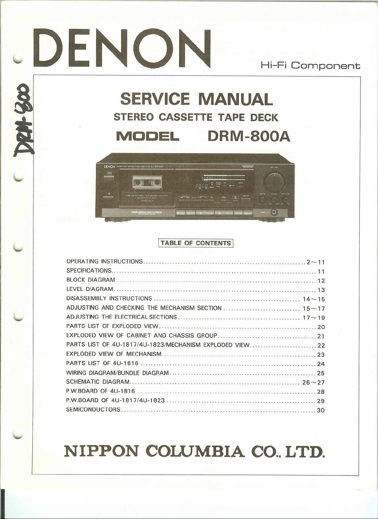
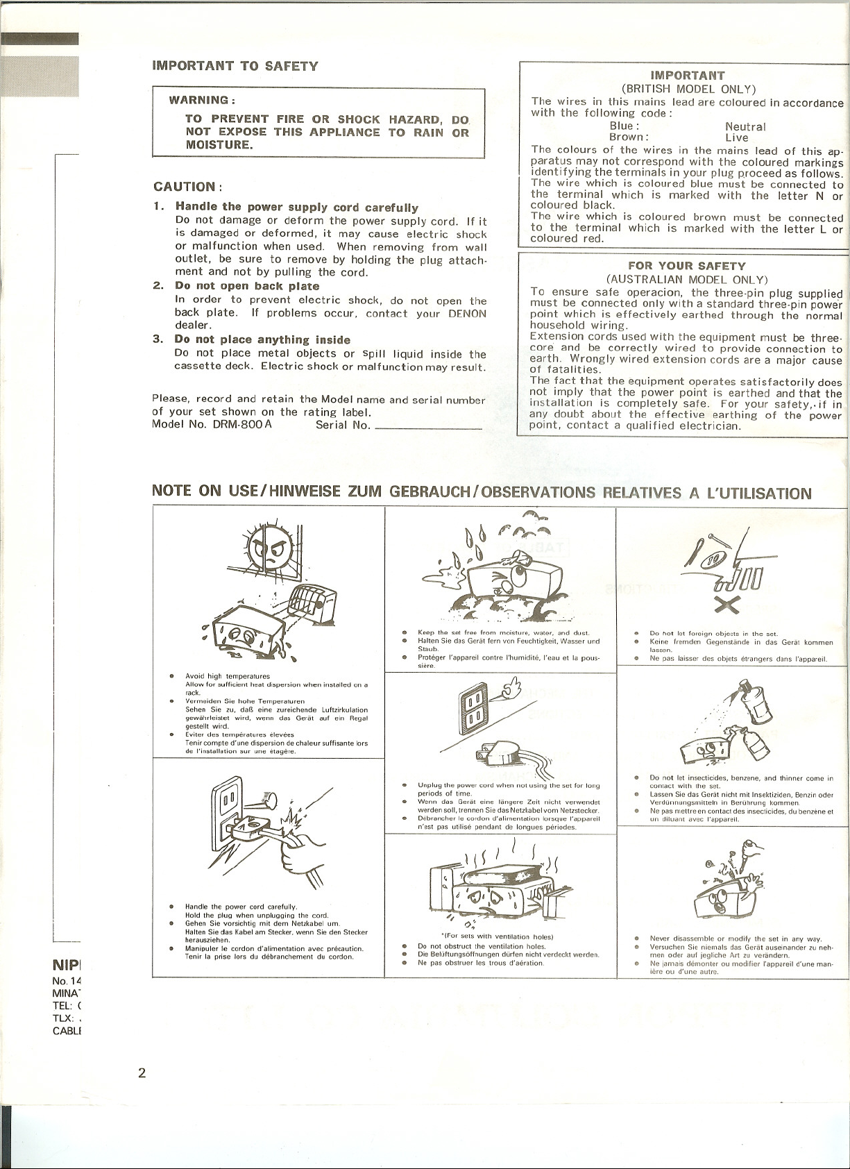
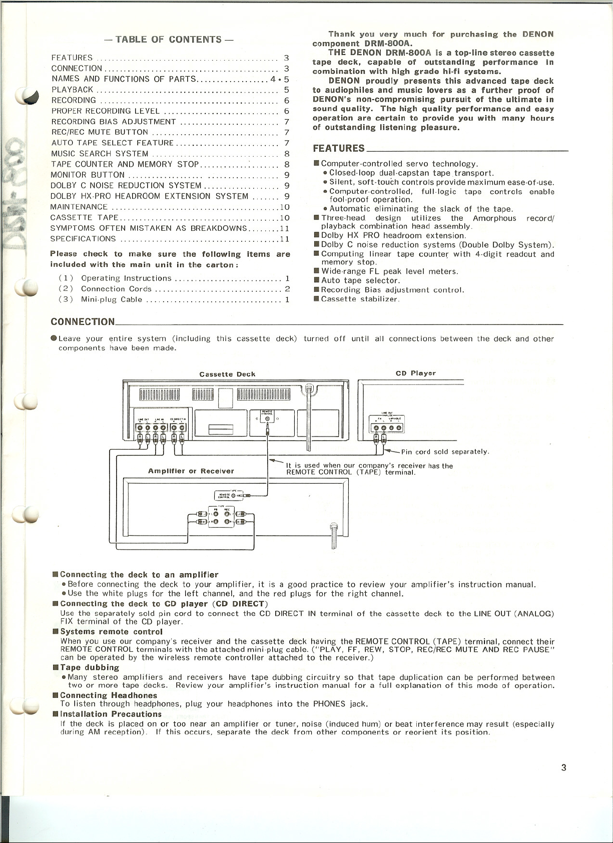
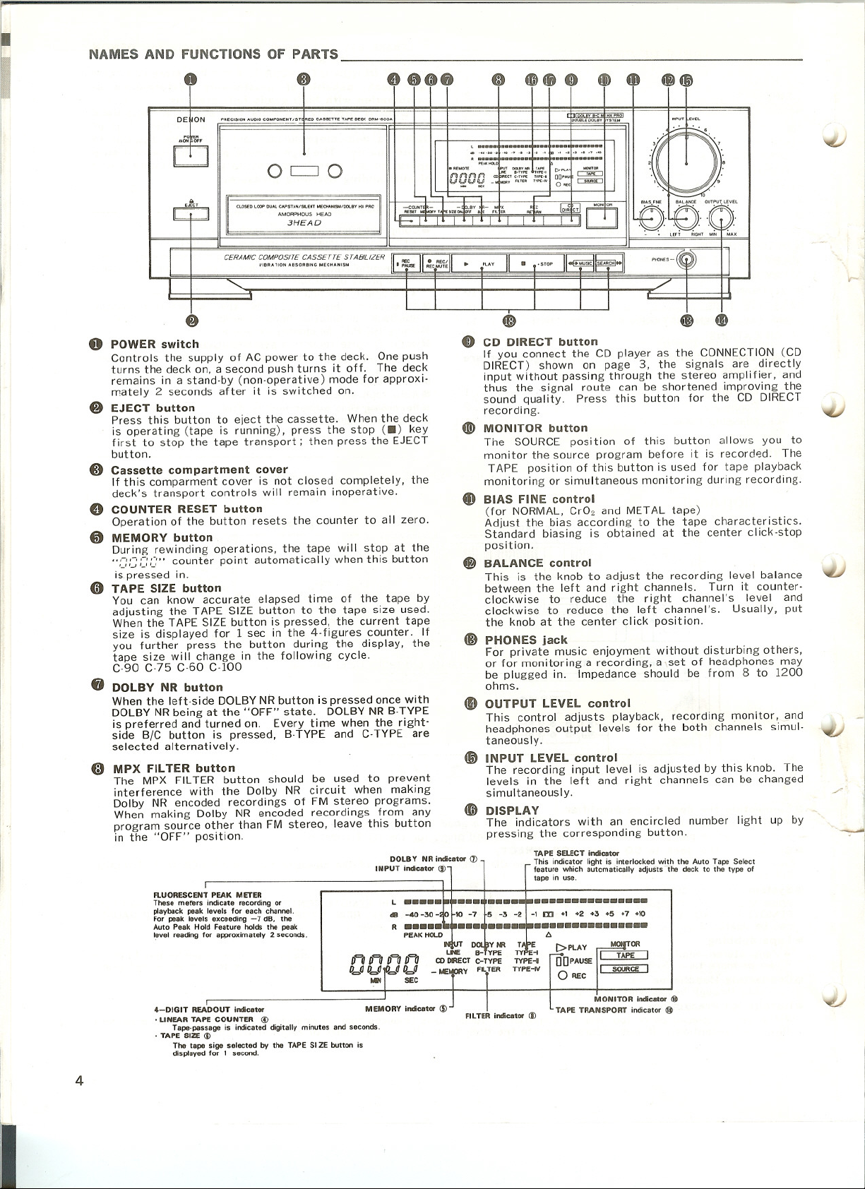
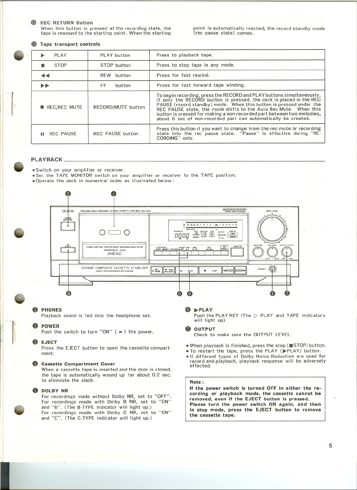
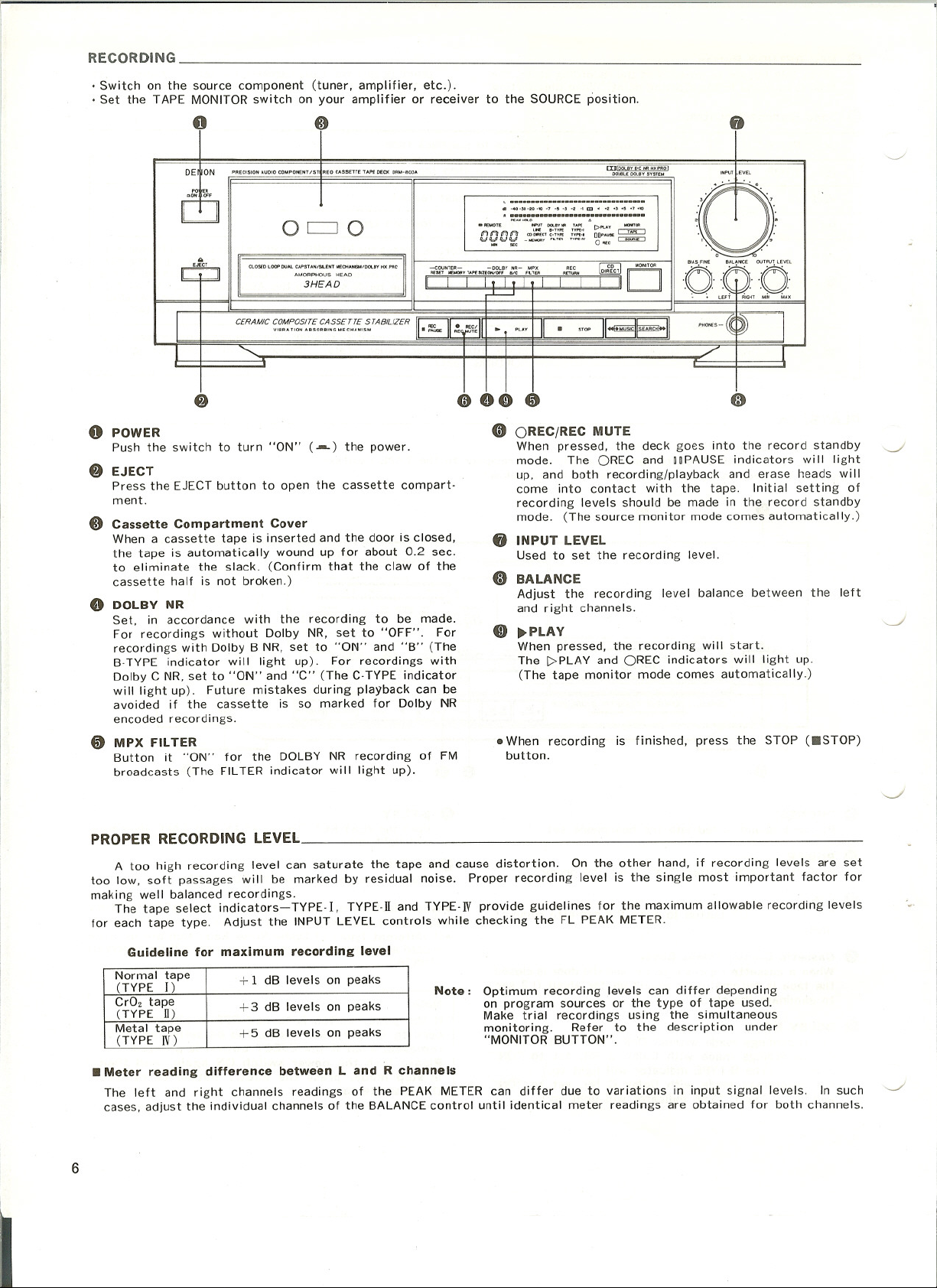
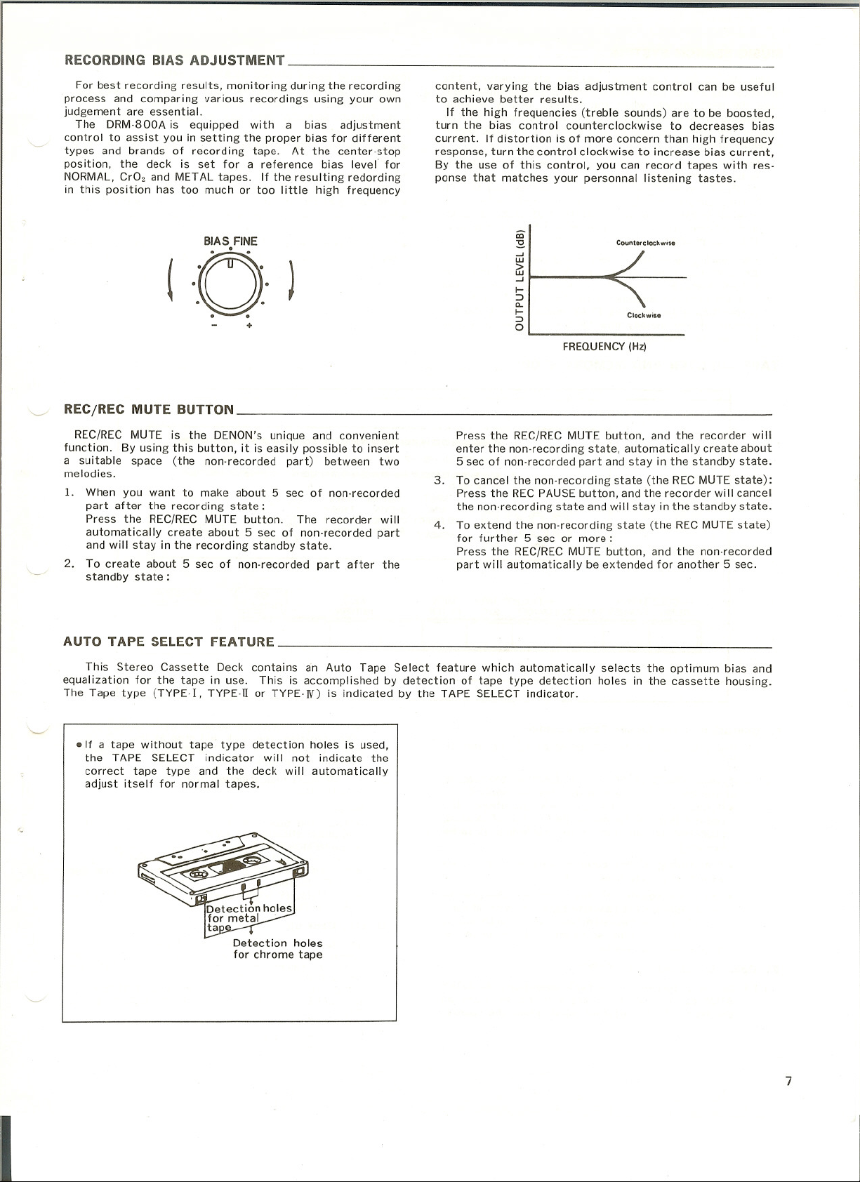
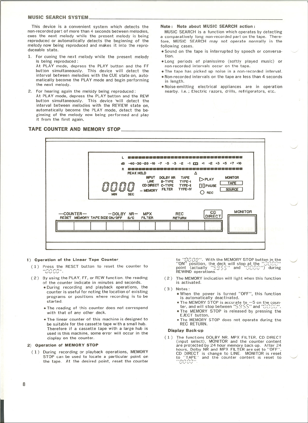
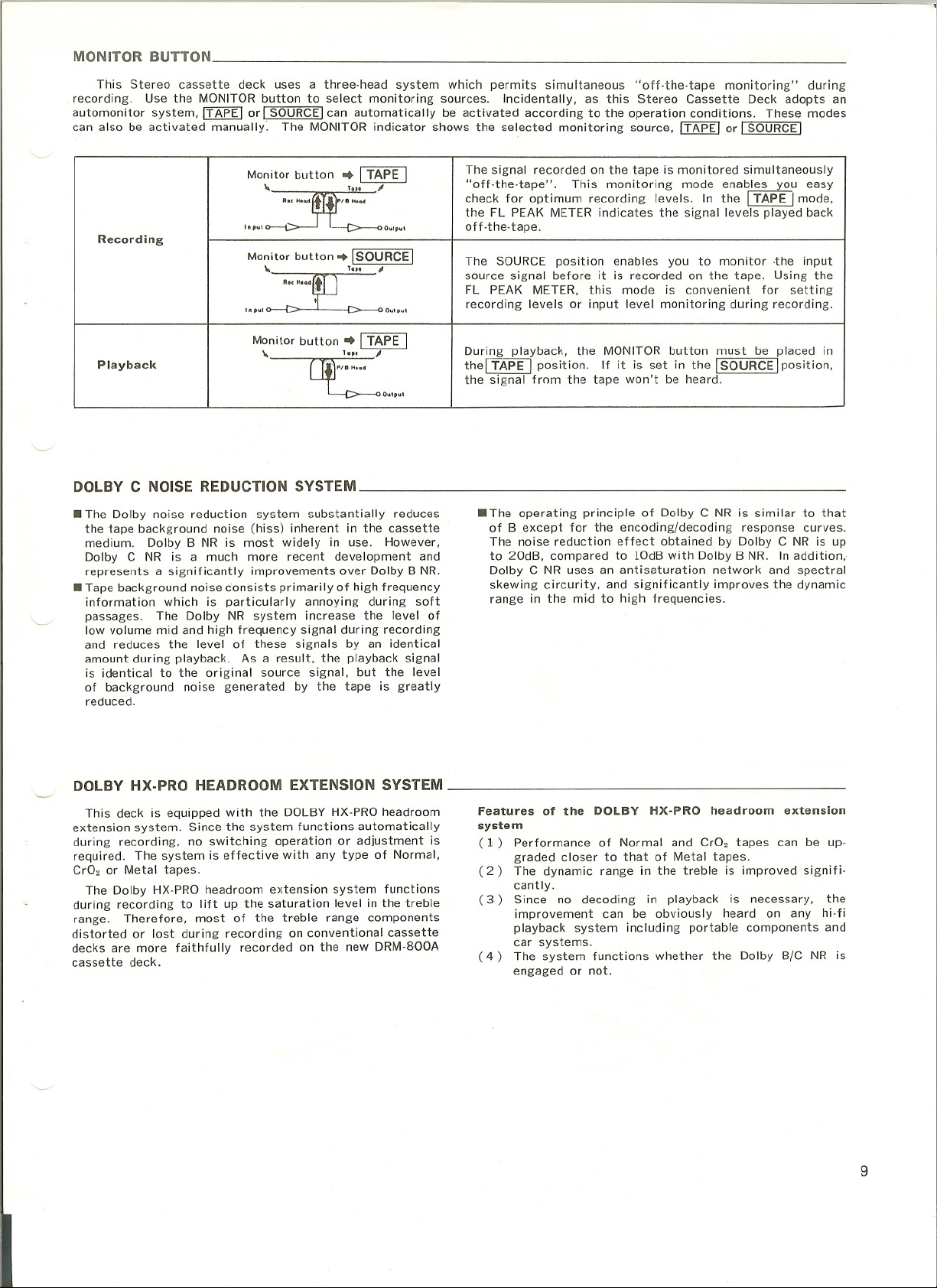
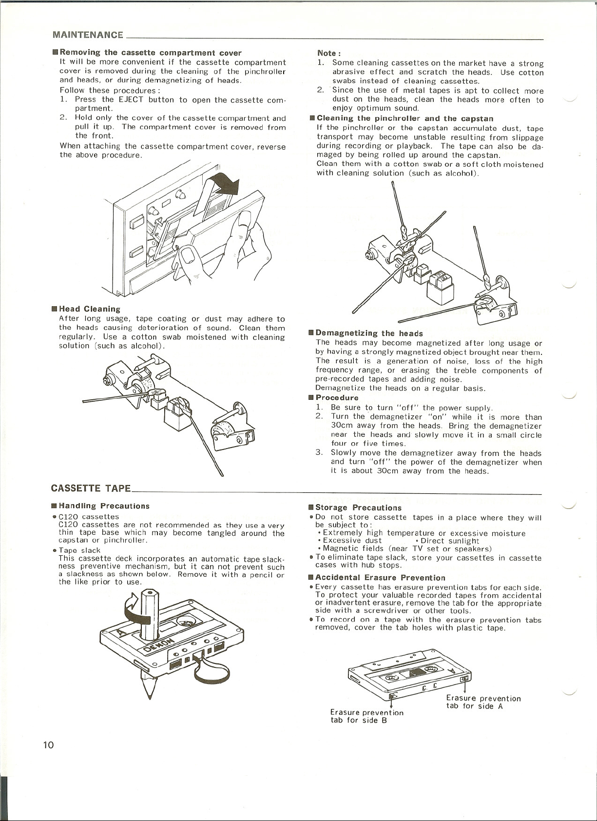
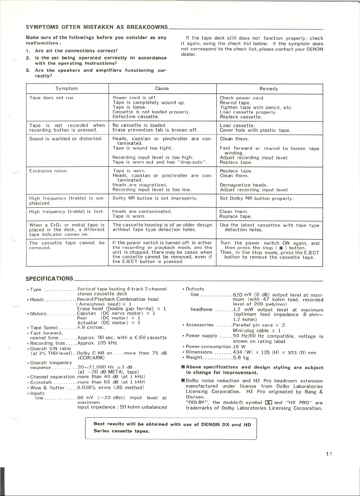
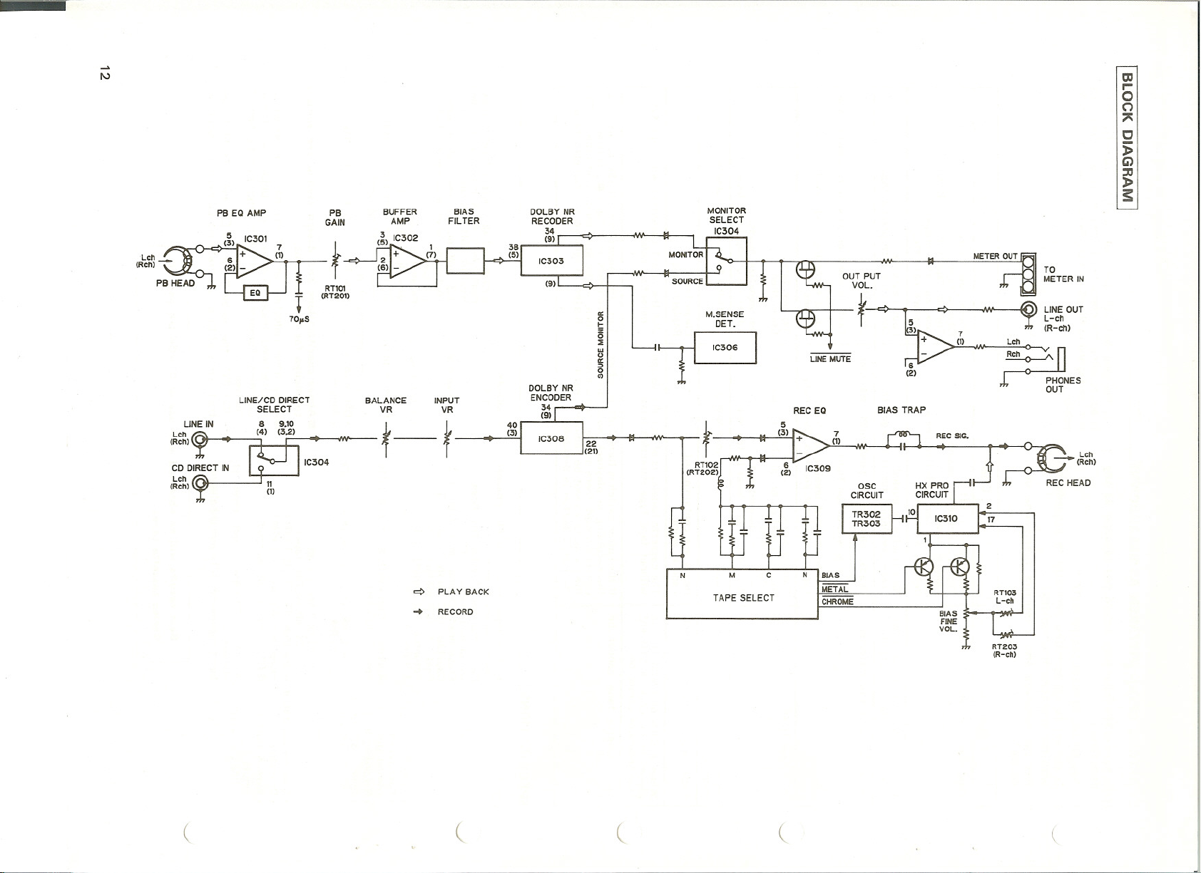
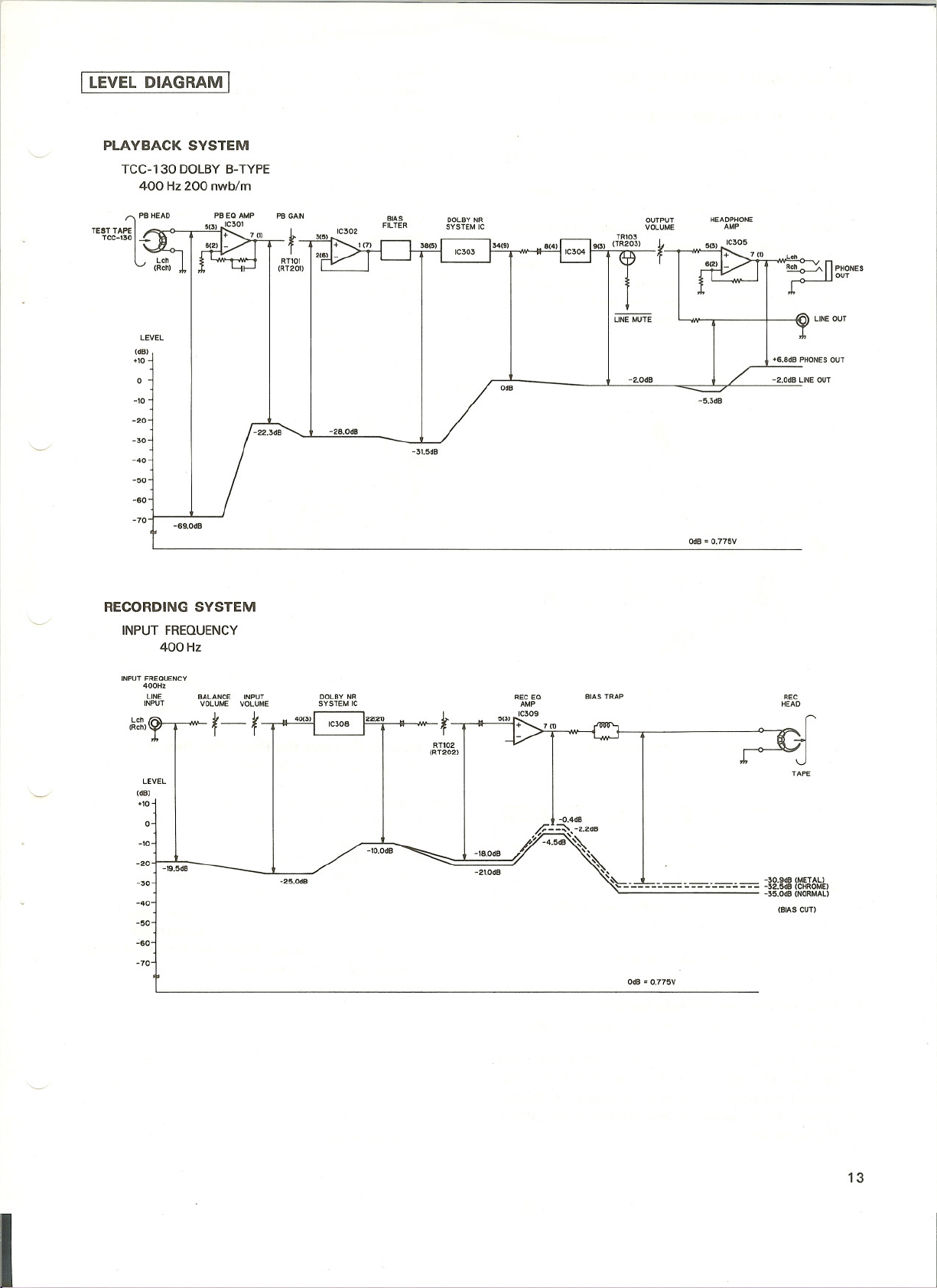


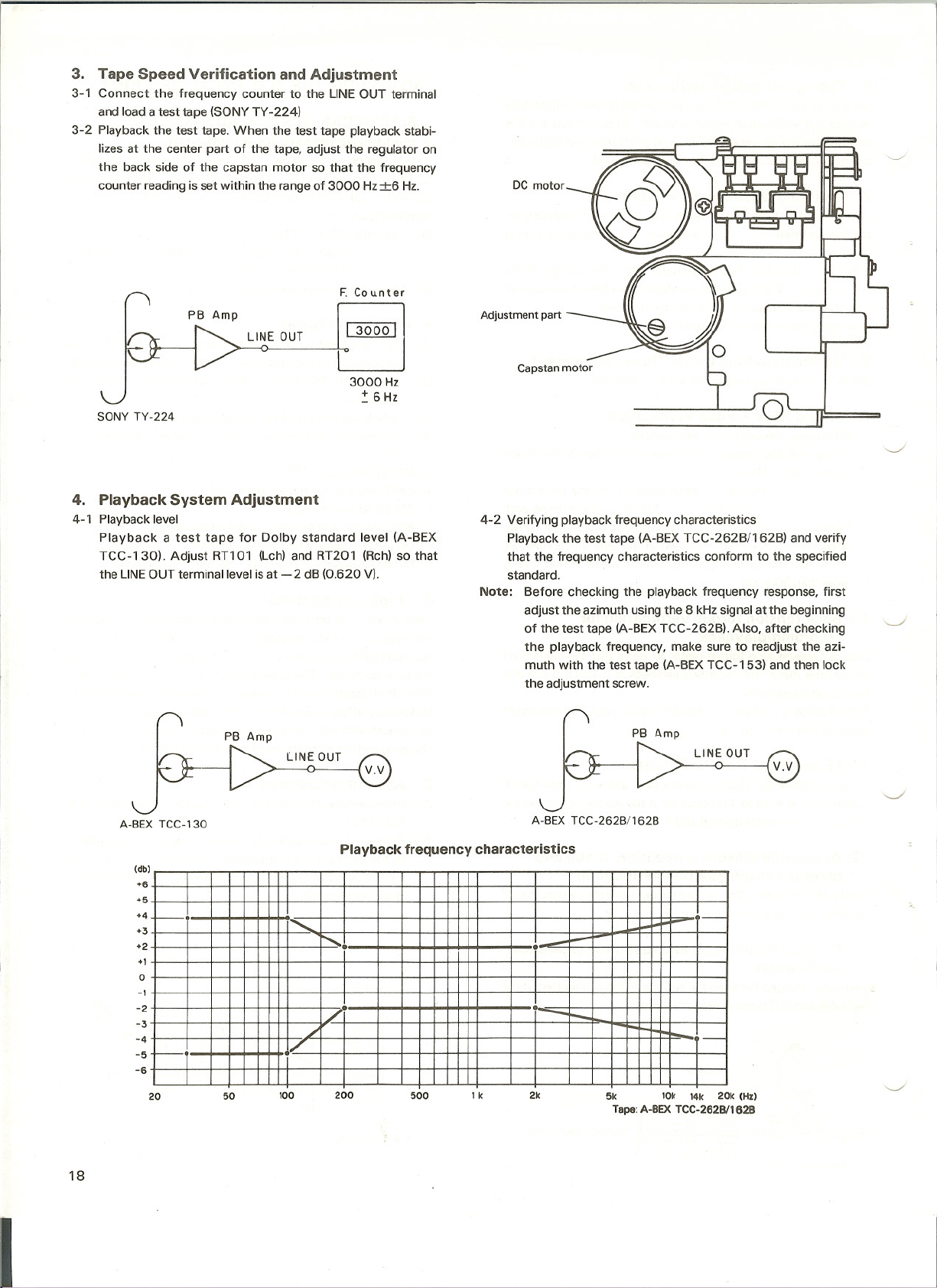


 Loading...