

Page 1
STEREO CASSETTE TAPE DECK
DRM-555
OPERATING INSTRUCTIONS
MODE D’EMPLOI
INSTRUCCIONES DE OPERACION
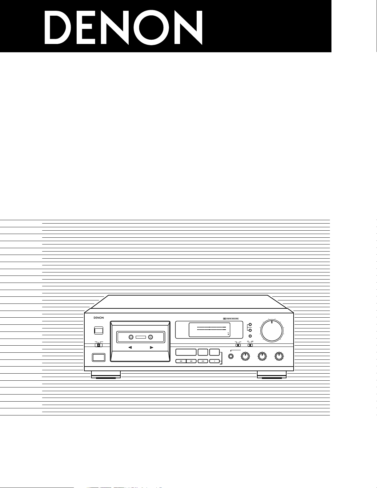
PRECISION AUDIO COMPONENT/CASSETTE TAPE DECK DRM-555
REMOTE SENSOR
L
R
-40 +10-30 +5-20 +3-10 +1-5 0-3 -1
‚¤‚‚
PLAY
2 STOP 3 REC PAUSE
REC/REC MUTE
PHONES
RESET
INPUT LEVEL
EJECT
5
¢ON £OFF
COUNTER
MEMORY
MPX
B OFF C
DOLBY NR
REC OFF PLAY.
TIMER
REV.MODE
PHONE LEVEL
MIN MAX
-
+ LEFT RIGHT
BIAS FINE BALANCE
DIRECTION
CD SYNCHRO REC
5
4
10
3
9
2
8
1
7
0
6
AUTO REVERSE
HIGH SPEED DUBBING SYSTEM
dB
FOR ENGLISH READERS PAGE 05 ~ PAGE 16
POUR LES LECTEURS FRANCAIS PAGE 17 ~ PAGE 28
PARA LECTORES DE ESPAÑOL PAGINA 29 ~ PAGINA 37
Page 2
2
IMPORTANT TO SAFETY
WARNING:
TO PREVENT FIRE OR SHOCK HAZARD, DO NOT EXPOSE THIS
APPLIANCE TO RAIN OR MOISTURE.
Please, record and retain the Model name and serial number of your set shown
on the rating label.
Model No. DRM-555 Serial No.
CAUTION:
1. Handle the power supply cord carefully
Do not damage or deform the power supply cord. If it is damaged or
deformed, it may cause electric shock or malfunction when used. When
removing from wall outlet, be sure to remove by holding the plug
attachment and not by pulling the cord.
2. Do not open the top cover
In order to prevent electric shock, do not open the top cover.
If problems occur, contact your DENON DEALER.
3. Do not place anything inside
Do not place metal objects or spill liquid inside the cassette tape deck.
Electric shock or malfunction may result.
CAUTION: TO REDUCE THE RISK OF ELECTRIC SHOCK, DO NOT
REMOVE COVER (OR BACK). NO USER-SERVICEABLE PARTS INSIDE.
REFER SERVICING TO QUALIFIED SERVICE PERSONNEL.
The lightning flash with arrowhead symbol, within an
equilateral triangle, is intended to alert the user to the
presence of uninsulated “dangerous voltage” within the
product’s enclosure that may be of sufficient magnitude to
constitute a risk of electric shock to persons.
The exclamation point within an equilateral triangle is
intended to alert the user to the presence of important
operating and maintenance (servicing) instructions in the
literature accompanying the appliance.
• FOR U.S.A. & CANADA MODEL ONLY
CAUTION
TO PREVENT ELECTRIC SHOCK DO NOT USE THIS (POLARIZED) PLUG
WITH AN EXTENSION CORD, RECEPTACLE OR OTHER OUTLET UNLESS
THE BLADES CAN BE FULLY INSERTED TO PREVENT BLADE
EXPOSURE.
• POUR LES MODELES AMERICAINS ET CANADIENS UNIQUEMENT
ATTENTION
POUR PREVENIR LES CHOCS ELECTRIQUES NE PAS UTILISER CETTE
FICHE POLARISEE AVEC UN PROLONGATEUR UNE PRISE DE COURANT
OU UNE AUTRE SORTIE DE COURANT, SAUF SI LES LAMES PEUVENT
ETRE INSEREES A FOND SANS EN LAISSER AUCUNE PARTIE A
DECOUVERT.
This device complies with Part 15 of the FCC Rules. Operation is subject to
the following two conditions: (1) This device may not cause harmful
interference, and (2) this device must accept any interference received,
including interference that may cause undesired operation.
This Class B digital apparatus meets all requirements of the Canadian
Interference-Causing Equipment Regulations.
Cet appareil numérique de la classe B respecte toutes les exigences du
Règlement sur le matériel brouilleur du Canada.
CAUTION
RISK OF ELECTRIC SHOCK
DO NOT OPEN
Page 3
3
SAFETY INSTRUCTIONS
1. Read Instructions – All the safety and operating
instructions should be read before the appliance is
operated.
2. Retain Instructions – The safety and operating instructions
should be retained for future reference.
3. Heed Warnings – All warnings on the appliance and in the
operating instructions should be adhered to.
4. Follow Instructions – All operating and use instructions
should be followed.
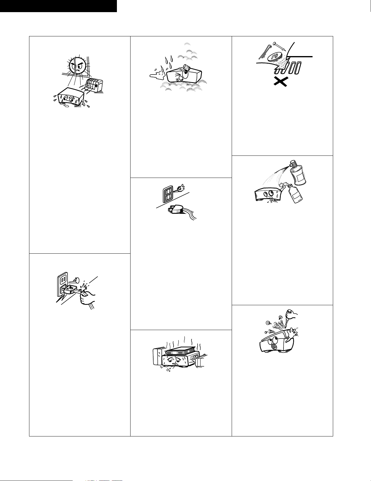
5. Water and Moisture – The appliance should not be used
near water – for example, near a bathtub, washbowl,
kitchen sink, laundry tub, in a wet basement, or near a
swimming pool, and the like.
6. Carts and Stands – The appliance should be used only with
a cart or stand that is recommended by the manufacturer.
6A. An appliance and cart
combination should be
moved with care.
Quick stops, excessive
force, and uneven
surfaces may cause
the appliance and cart
combination to overturn.
7. Wall or Ceiling Mounting – The appliance should be
mounted to a wall or ceiling only as recommended by the
manufacturer.
8. Ventilation – The appliance should be situated so that its
location or position does not interfere with its proper
ventilation. For example, the appliance should not be
situated on a bed, sofa, rug, or similar surface that may
block the ventilation openings; or, placed in a built-in
installation, such as a bookcase or cabinet that may
impede the flow of air through the ventilation openings.
9. Heat – The appliance should be situated away from heat
sources such as radiators, heat registers, stoves, or other
appliances (including amplifiers) that produce heat.
10. Power Sources – The appliance should be connected to a
power supply only of the type described in the operating
instructions or as marked on the appliance.
11. Grounding or Polarization – Precautions should be taken so
that the grounding or polarization means of an appliance is
not defeated.
12. Power-Cord Protection – Power-supply cords should be
routed so that they are not likely to be walked on or
pinched by items placed upon or against them, paying
particular attention to cords at plugs, convenience
receptacles, and the point where they exit from the
appliance.
14. Cleaning – The appliance should be cleaned only as
recommended by the manufacturer.
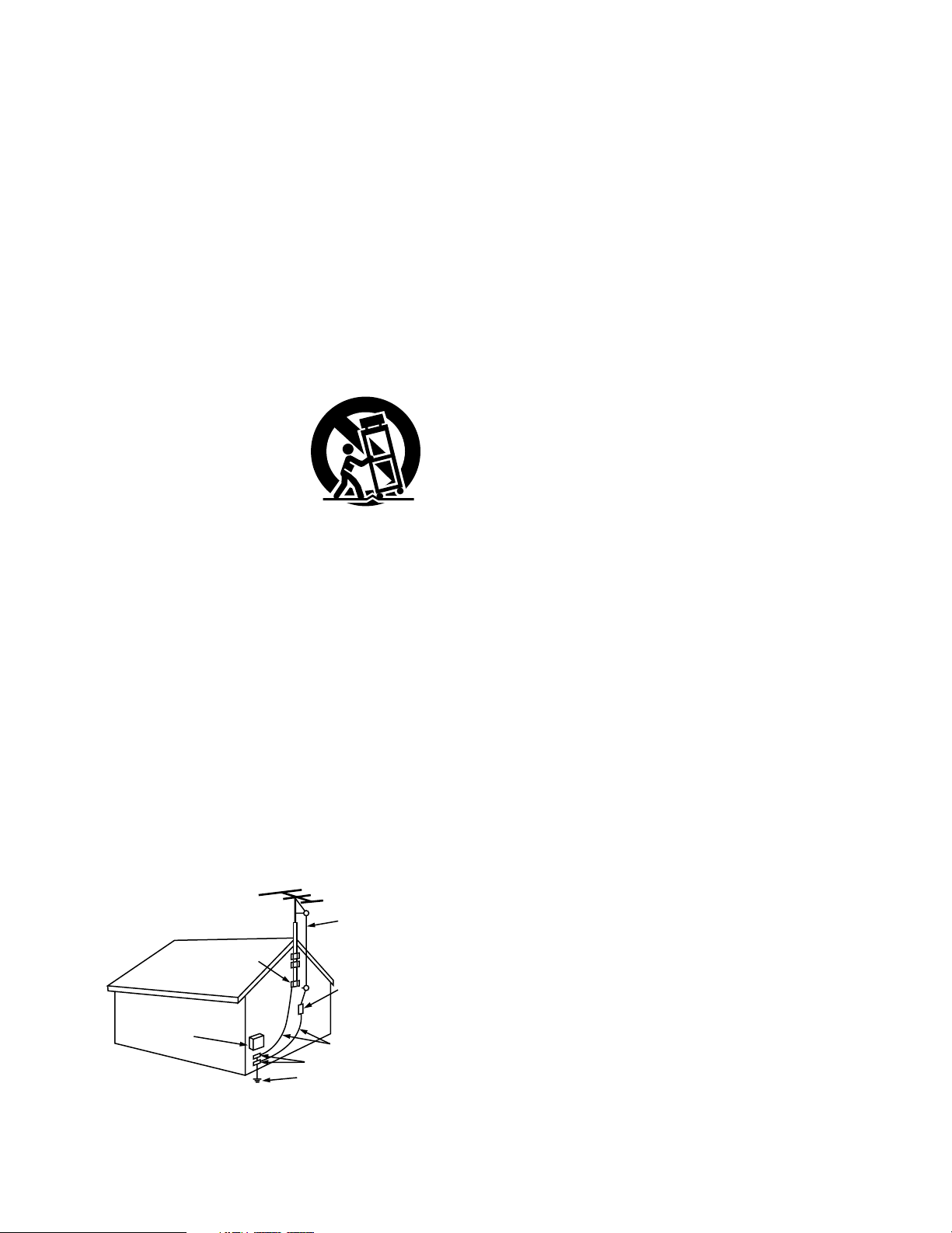
15. Power Lines – An outdoor antenna should be located away
from power lines.
16. Outdoor Antenna Grounding – If an outside antenna is
connected to the receiver, be sure the antenna system is
grounded so as to provide some protection against voltage
surges and built-up static charges. Article 810 of the
National Electrical Code, ANSI/NFPA 70, provides
information with regard to proper grounding of the mast
and supporting structure, grounding of the lead-in wire to
an antenna-discharge unit, size of grounding conductors,
location of antenna-discharge unit, connection to grounding
electrodes, and requirements for the grounding electrode.
See Figure A.
17. Nonuse Periods – The power cord of the appliance should
be unplugged from the outlet when left unused for a long
period of time.
18. Object and Liquid Entry – Care should be taken so that
objects do not fall and liquids are not spilled into the
enclosure through openings.
19. Damage Requiring Service – The appliance should be
serviced by qualified service personnel when:
A. The power-supply cord or the plug has been damaged;
or
B. Objects have fallen, or liquid has been spilled into the
appliance; or
C. The appliance has been exposed to rain; or
D. The appliance does not appear to operate normally or
exhibits a marked change in performance; or
E. The appliance has been dropped, or the enclosure
damaged.
20. Servicing – The user should not attempt to service the
appliance beyond that described in the operating
instructions. All other servicing should be referred to
qualified service personnel.
FIGURE A
EXAMPLE OF ANTENNA GROUNDING
AS PER NATIONAL
ELECTRICAL CODE
ANTENNA
LEAD IN
WIRE
GROUND
CLAMP
ELECTRIC
SERVICE
EQUIPMENT
ANTENNA
DISCHARGE UNIT
(NEC SECTION 810-20)
GROUNDING CONDUCTORS
(NEC SECTION 810-21)
GROUND CLAMPS
POWER SERVICE GROUNDING
ELECTRODE SYSTEM
(NEC ART 250, PART H)
NEC - NATIONAL ELECTRICAL CODE
Page 4
4
ENGLISH FRANCAIS ESPAÑOL
NOTE ON USE / OBSERVATIONS RELATIVES A L’UTILISATION / NOTAS SOBRE EL USO
• Avoid high temperatures.
Allow for sufficient heat dispersion
when installed on a rack.
• Eviter des températures élevées
Tenir compte d’une dispersion de
chaleur suffisante lors de l’installation
sur une étagère.
• Evite altas temperaturas.
Permite la suficiente dispersión del
calor cuando está instalado en la
consola.
• Keep the set free from moisture,
water, and dust.
• Protéger l’appareil contre l’humidité,
l’eau et lapoussière.
• Mantenga el equipo libre de
humedad, agua y polvo.
• Do not let foreign objects in the set.
• Ne pas laisser des objets étrangers
dans l’appareil.
• No deje objetos extraños dentro del
equipo.
• Do not let insecticides, benzene, and
thinner come in contact with the set.
• Ne pas mettre en contact des
insecticides, du benzène et un diluant
avec l’appareil.
• No permita el contacto de
insecticidas, gasolina y diluyentes con
el equipo.
• Never disassemble or modify the set
in any way.
• Ne jamais démonter ou modifier
l’appareil d’une manière ou d’une
autre.
• Nunca desarme o modifique el equipo
de ninguna manera.
• Unplug the power cord when not
using the set for long periods of time.
• Débrancher le cordon d’alimentation
lorsque l’appareil n’est pas utilisé
pendant de longues périodes.
• Desconecte el cordón de energía
cuando no utilice el equipo por mucho
tiempo.
* (For sets with ventilation holes)
• Do not obstruct the ventilation holes.
• Ne pas obstruer les trous d’aération.
• No obstruya los orificios de
ventilación.
• Handle the power cord carefully.
Hold the plug when unplugging the
cord.
• Manipuler le cordon d’alimentation
avec précaution.
Tenir la prise lors du débranchement
du cordon.
• Maneje el cordón de energía con
cuidado.
Sostenga el enchufe cuando
desconecte el cordón de energía.
Page 5
ENGLISH
5
Thank you very much for purchasing the DENON component stereo cassette
tape deck.
DENON proudly presents this advanced tape deck to audiophiles and music
lovers as a further proof of DENON’s non-compromising pursuit of the ultimate
in sound quality. The high quality performance and easy operation are certain to
provide you with many hours of outstanding listening pleasure.
— TABLE OF CONTENTS —
FEATURES ……………………………………………………………………………5
CONNECTION ………………………………………………………………………5
NAMES AND FUNCTIONS OF PARTS …………………………………………6, 7
CASSETTE TAPES ……………………………………………………………………7
AUTOMATIC TAPE SELECTION ……………………………………………………8
PLAYBACK …………………………………………………………………………8, 9
MUSIC SEARCH SYSTEM ………………………………………………………9
RECORDING …………………………………………………………………………10
PROPER RECORDING LEVEL …………………………………………………10
RECORDING BIAS ADJUSTMENT ……………………………………………11
REC/REC MUTE AND REC PAUSE BUTTON ………………………………11
DIMMER ADJUSTMENT …………………………………………………………11
SYNCHRONIZED RECORDING FUNCTION ……………………………………12
TAPE COUNTER AND MEMORY STOP …………………………………………13
TIMER RECORDING/PLAYBACK …………………………………………………14
DOLBY B AND C NOISE REDUCTION SYSTEM ………………………………15
DOLBY HX-PRO HEADROOM EXTENSION SYSTEM …………………………15
MAINTENANCE ……………………………………………………………………15
TROUBLESHOOTING ………………………………………………………………16
SPECIFICATIONS ……………………………………………………………………16
Please check to make sure the following items are included with the main
unit in the carton:
(1) Operating Instructions …………………………………………………1
(2) Connection Cords ………………………………………………………2
(3) Mini-Plug Cable …………………………………………………………1
FEATURES
2 Computer Controlled Mechanism
2 Dual Power Supply
2 Dolby HX-Pro Headroom Extension System
2 Dolby B & C Noise Reduction Systems
2 Manual Bias Adjustment Control
2 Computing Tape Counter with 4-Digit Readout and Memory Stop
2 Music Search System
2 FL Peak Level Meters
2 Auto Tape Selector
2 Synchronized Recording
2 Timer Play and Timer Recording
2 Optional Remote Controllable
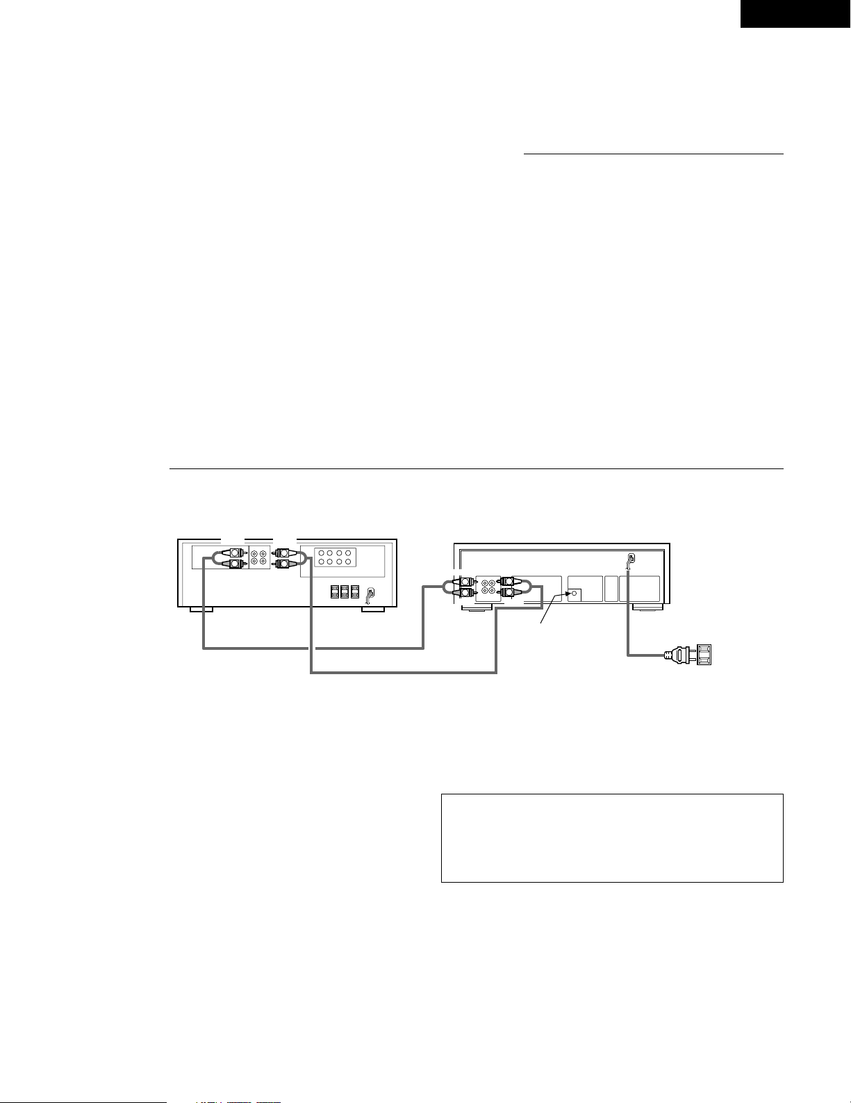
CONNECTION
• Leave your entire system (including this cassette deck) turned off until all connections between the deck and other components have been completed.
VOLTAGE
SELECTOR
115V 230V
PRESET
LINE
OUT
LINE
IN
L
R
SYNCHRO
TAPE-1
PB
REC
L
R
R
L
R
L
L
R
L
R
LINE
OUT IN
Receiver or amplifier
This jack is for the synchronized
recording function only.
Do not plug in microphones,
headphones nor other plugs.
Power supply
outlet.
60 Hz
DRM-555
2
Connecting the Deck to an Amplifier
• Before connecting the deck to your amplifier, please review your
amplifier’s instruction manual.
• Use the white plugs for the left channel and red plugs for the right
channel.
2 Tape Dubbing
• Many stereo amplifiers and receivers have tape dubbing circuitry so that
tape duplication can be performed between two or more tape decks.
Review your amplifier’s instruction manual for a full explanation of this
mode of operation.
2 Connecting Headphones
To listen through headphones, plug your headphones into the PHONES
jack.
2 Installation Precautions
If the deck is placed near an amplifier, TV or tuner, noise (induced hum) or
beat interference may result, especially during FM or AM reception. If this
occurs, place the deck further away from other components or reorient its
position.
Caution:
A mechanical sound is heard the first time the power switch is set to “ON”
after the power cord is plugged into an outlet. This is the sound of the
cassette mechanism being set to the proper operating state, and is normal.
(When using an AC outlet on a receiver or amplifier, used an
“UNSWITCHED” outlet.)
WHITE
WHITE
WHITE
WHITE
RED
RED
RED
RED
Page 6
ENGLISH
6
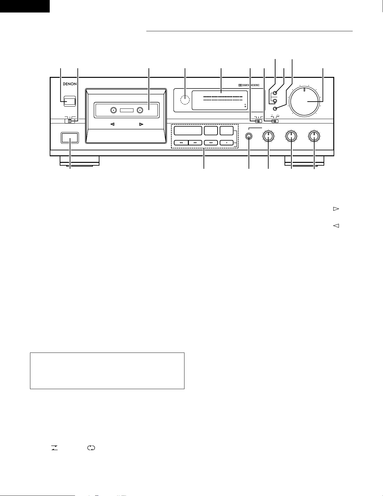
NAMES AND FUNCTIONS OF PARTS
q
Power Operation Switch (¢ ON £ OFF)
• Press once to turn the power to deck on, and once more to turn the
power off.
• The deck remains in a stand-by (non-operative) mode for
approximately 2 seconds after it is switched on.
w
Eject Button (EJECT 5 )
• Press this button to open the cassette compartment cover. When the
tape is running, press the Stop button (
2 STOP) first to stop tape
transport, then press the Eject button (EJECT
5).
e
Timer Switch (TIMER)
• This switch is provided for use with an optional audio timer for
unattended recording or morning-alarm playback.
• For non-timer operation, this switch should be set in the “OFF”
position. See page 14.
r
Cassette Compartment Cover
• If the cover is not closed completely, the tape transport buttons will
remain inoperative.
t
Remote Sensor (REMOTE SENSOR)
• With the cassette deck the remote control unit is not included.
• Each of “Play, Fast Forward, Fast Rewind, Stop, Rec Pause and
Rec/Rec Mute” functions can be remote controlled with wireless
handset of the receiver (DRA Series receivers). For details refer to the
DRA Series operating instructions.
o
Counter Memory Button (MEMORY)
• When this button is pressed during forward tape travel ( ), fast
rewinding (
6 ) will stop automatically at the tape counter position
“‚‚‚‚”.
• When this button is pressed during reverse tape travel ( ), fast
forwarding (
7 ) will stop automatically at the tape counter position
“‚‚‚‚”. See page 13.
!0
Counter Reset Button (RESET)
• Press this button to reset the tape counter to zero.
!1
MPX Filter Button (MPX)
• The MPX Filter button (MPX) should be used to prevent interference
with the Dolby NR circuit when making Dolby NR encoded recordings
of FM stereo programs.
• When making Dolby NR encoded recordings from any program
source other than FM stereo, leave this button in the “OFF” position.
!2
Input Level Control (INPUT LEVEL)
• This knob adjusts the recording input level. It affects the level in both
channels. See page 10.
!3
Balance Control (BALANCE)
• This is the knob to adjust the recording level balance between the left
and right channels. Turn it counter-clockwise to reduce the right
channel’s level and clockwise to reduce the left channel’s. Usually,
put the knob at the center click position.
!4
Bias Fine Control (BIAS FINE)
(For Normal, CrO2 and Metal tape)
• Use this control to fine-adjust the bias. Standard bias is obtained at
the center click-stop position. See page 11.
!5
Phone Level Control (PHONE LEVEL)
• Head phone output level is adjusted by this knob. The levels in the left
and right channels can be changed simultaneously.
!6
Headphone Jack (PHONES)
• For private music enjoyment without disturbing others, or for
monitoring a recording, a headphone set may be connected to this
jack. Use a headphone with an impedance rating of 8 to 1200
Ω/ohms.
PRECISION AUDIO COMPONENT/CASSETTE TAPE DECK DRM-555
REMOTE SENSOR
L
R
-40 +10-30 +5-20 +3-10 +1-5 0-3 -1
‚¤‚‚
PLAY
2 STOP 3 REC PAUSE
REC/REC MUTE
PHONES
RESET
INPUT LEVEL
EJECT
5
¢ON £OFF
COUNTER
MEMORY
MPX
B OFF C
DOLBY NR
REC OFF PLAY.
TIMER
REV.MODE
PHONE LEVEL
MIN MAX
-
+ LEFT RIGHT
BIAS FINE BALANCE
DIRECTION
CD SYNCHRO REC
5
4
10
3
9
2
8
1
7
0
6
AUTO REVERSE
HIGH SPEED DUBBING SYSTEM
dB
we r t y
u
i!2
o
!0
!1
q
!7
!6 !5
!4
!3
Caution:
Whenever the Power Operation switch is in the OFF state, the apparatus is
still connected on AC line voltage.
Please be sure to unplug the cord when you leave home for, say, a
vacation.
y
Display
u
Dolby NR Switch (DOLBY NR)
• To record or playback tapes with Dolby B or C-type noise reduction,
set this switch to “B” or “C”. Turn it “OFF” when not using the
Dolby NR system.
i
Reverse Mode Switch (REV. MODE)
• Select the type of tape transport. The reverse mode can be set to
(one side), (continuous playback).
Page 7

ENGLISH
7
y
Display
• Indicators with an encircled number light up when the corresponding button is pressed.
L
R
-40 +10-30 +5-20 +3-10 +1-5 0-3 -1
SYNCMPX
MEMO
dB
Peak Level Meter
MPX Filter
Indicator
Remote
Control Indicator
Indicates the recording and playback signal levels for
the left and right channels.
Tape Transport Indicators
Memory Indicator
Tape Counter
Synchro Rec Indicator (See page 12)
CASSETTE TAPES
2 Handling Precautions
• C-120 cassette tapes
C-120 cassette tapes are not recommended as they use a very thin tape
base which may become tangled around the capstan or pinch roller.
• Tape Slack
Before putting a tape into the deck, take up any slack with a pencil or your
finger tip. This precaution prevents the tape from becoming entangled
around the capstan or pinch roller.
A
2 Storage Precautions
• Do not store cassette tapes in a place where they will be subject to:
• Extremely high temperature or excessive moisture
• Excessive dust
• Direct sunlight
• Magnetic fields (near TV sets or speakers)
• To eliminate tape slack, store your cassettes in cassette cases with hub
stops
2 Accidental Erasure Prevention
• All cassettes have erasure prevention tabs for each side. To protect valuable
recordings from accidental or inadvertent erasure, remove the tab for the
appropriate side with a screwdriver or another tool.
• To record on a tape whose erasure prevention tabs have been removed,
cover the tab holes with adhesive tape.
Erasure prevention tab for side B
Erasure prevention tab for side A
!7
Tape Transport Buttons
Play Button
Stop Button
Fast Rewind Button
Fast Forward Button
Rec/Rec Mute
Button
Rec Pause Button
Direction Button
Press to playback tape.
Press to stop the tape in any mode.
Press for fast rewind.
Press for fast forwarding.
Press the Rec/Rec Mute button (REC/REC MUTE) (
4 ) and Play button (PLAY) simultaneously to
start recording. If only the Rec/Rec Mute button (REC/REC MUTE) (
4 ) is pressed, the deck enters
the recording pause mode. Pressing this button in the recording pause mode will start Auto Rec
Mute, and a 5-second silent space is recorded onto the tape.
Press this button to enter the recording pause mode from the recording or recording mute mode.
This button can only be used during recording.
Changes the tape transport direction from forward “
1” to reverse “0”, and vice versa.
PLAY
2 STOP
6
7
4
3 REC PAUSE
01
Side A
Page 8

ENGLISH
8
PLAYBACK
q Press the Power Operation switch to the ¢ ON position.
w Press the Eject button (EJECT
5 ) to open the cassette compartment
cover.
e Load the cassette tape and close the cassette compartment cover.
r When listening to a tape that has been recorded with Dolby noise
reduction, set the Dolby NR switch (DOLBY NR) to match the system used
at the time of recording.
B OFF C
DOLBY NR
t Press the Direction button ( 01) to select the direction of tape transport.
IndicatorTransport Direction
Forward
Reverse
• Switch on your amplifier or receiver.
• Set the Tape Monitor switch on your amplifier or receiver to the TAPE position.
• The numbers in the illustration below depict the order in which operation steps are carried out.
PRECISION AUDIO COMPONENT/CASSETTE TAPE DECK DRM-555
REMOTE SENSOR
L
R
-40 +10-30 +5-20 +3-10 +1-5 0-3 -1
‚¤‚‚
PLAY
2 STOP 3 REC PAUSE
REC/REC MUTE
PHONES
RESET
INPUT LEVEL
EJECT
5
¢ON £OFF
COUNTER
MEMORY
MPX
B OFF C
DOLBY NR
REC OFF PLAY.
TIMER
REV.MODE
PHONE LEVEL
MIN MAX
-
+ LEFT RIGHT
BIAS FINE BALANCE
DIRECTION
CD SYNCHRO REC
5
4
10
3
9
2
8
1
7
0
6
AUTO REVERSE
HIGH SPEED DUBBING SYSTEM
dB
AUTOMATIC TAPE SELECTION
This Stereo Cassette Deck contains an automatic tape selector which
automatically selects the optimum bias and equalization for the tape in use.
This is accomplished by detection of the tape type detections holes in the
cassette housing.
• If a tape without tape type detection holes is used, the deck will be set
for normal tapes.
Detection holes
for metal tape
Detection holes for
chrome tape
Page 9

ENGLISH
9
y Select the type of tape transport with the Reverse Mode switch (REV.
MODE).
REV.MODE
Switch positionMode
To listen to one side only
To listen to repeat playback
of both sides
u Press the Play button (PLAY) to begin playback.
i Press the Stop button (
2 STOP) to stop the playback.
• In the continuous playback mode (Reverse Mode switch (REV. MODE)
set to ), playback of both tape sides will be repeated 5 times and
then stop automatically.
• If different types of Dolby noise reduction are used for record and
playback, playback response will be adversely effected.
• When power is turned off during tape transport, it may not be possible to
remove the cassette by pressing the Eject button (EJECT
5 ).
In this case, turn on power again before you press the Eject button
(EJECT
5 ).
2 MUSIC SEARCH SYSTEM
The music search system detects blank sections (lasting for at least 4 seconds)
between selections in order to locate the beginning of selections in the
forward or reverse direction.
1. To advance from the current selection to the beginning of the next
selection (CUE):
Press the Play button (PLAY), and press the Fast Forward button (
7 )
when the tape is travelling in the forward ( ) direction.
Press the
Play button (PLAY)
, and press the Fast Rewind button (
6
)
when the tape is travelling in the reverse ( ) direction.
The tape transport indicator flashes.
The deck will skip the rest of the current selection and automatically
resume play from the beginning of the next selection.
2. To repeat playback from the beginning of the current selection (REVIEW):
Press the
Play button (PLAY)
, and press the Fast Rewind button ( 6 )
when the tape is travelling in the forward ( ) direction.
Press the Play button (PLAY), and press the Fast Forward button (
7 )
when the tape is travelling in the reverse ( ) direction.
The tape transport indicator flashes.
The deck will rewind the tape to the beginning of the current selection and
automatically resume play from that point.
This is very convenient for repeating playback of the current selection.
Notes on Music Search Operation:
The search functions operates by detecting comparatively long, blank sections
approximately 4 to 5 seconds long, in between recorded selections. Therefore,
the system may not operate normally in the following cases:
• Recordings with discontinuous speech or conversation.
• Recordings with long periods of pianissimo (softly played music).
• Recordings with long silences.
• Blank sections with a high level of noise.
• Blank sections shorter than 4 seconds.
• If noise-emitting appliances, such as electric razors, drills, refrigerators, etc.,
are operated nearby.
• REV. close to the beginning of the program or CUE close to the ending.
Page 10

ENGLISH
10
RECORDING
q Press the Power Operation switch to the ¢ ON position.
w Load the cassette tape.
(Check that the erasure prevention tabs of the cassette housing have not
been broken off.)
e Move the Dolby NR switch (DOLBY NR) and select the Dolby NR type that
suits the recording.
B OFF C
DOLBY NR
r Press the Direction button ( 01) to select the direction of tape transport.
t Select the type of tape transport with the Reverse Mode switch (REV.
MODE).
Switch positionMode
To record on only one side
To continuously record
on both sides
y Press the Rec/Rec Mute button (REC/REC MUTE) ( 4 ) to set the recording
pause mode. The
43indicator will light up.
u Adjust the recording level with the Input Level control (INPUT LEVEL)
while watching the Peak Level Meter.
i Press the Play button (PLAY) to start the recording.
The play ( or ) and the
4 indicator will light during recording.
o To pause the recording, press the Rec Pause button (
3 REC PAUSE).
Press the Play button (PLAY) to resume recording.
!0 To stop recording, press the Stop button (
2 STOP).
Caution:
• Be careful not to erase important recordings by mistake. Inadvertent start of
recording will happen in the following cases:
1. If the Play button (PLAY) is pressed while the
4 indicator lights, recording
starts.
2.
If the Play button (PLAY) and Rec/Rec Mute button (REC/REC MUTE)
( 4 ) are pressed at the same time, recording starts.
The best way to avoid accidental erasure is to break off the two erasure
prevention tabs on the cassette housing.
2 PROPER RECORDING LEVEL
A too high recording level can saturate the tape and cause distortion. On the
other hand, if the recording level is set too low, soft passages will be
marked by residual noise. A proper recording level is the single most
important factor for making well balanced recordings.
Guideline for maximum recording level
0 dB level on peaks
+1 dB level on peaks
+3 dB level on peaks
TYPE
I (Normal)
TYPE II (CrO2)
TYPE IV (Metal)
Note: The optimum recording level differs depending on the program source
and the type of tape used.
• Switch on your amplifier or receiver and the source component.
• Set the Tape Monitor switch on your amplifier or receiver to the SOURCE position.
PRECISION AUDIO COMPONENT/CASSETTE TAPE DECK DRM-555
REMOTE SENSOR
L
R
-40 +10-30 +5-20 +3-10 +1-5 0-3 -1
‚¤‚‚
PLAY
2 STOP 3 REC PAUSE
REC/REC MUTE
PHONES
RESET
INPUT LEVEL
EJECT
5
¢ON £OFF
COUNTER
MEMORY
MPX
B OFF C
DOLBY NR
REC OFF PLAY.
TIMER
REV.MODE
PHONE LEVEL
MIN MAX
-
+ LEFT RIGHT
BIAS FINE BALANCE
DIRECTION
CD SYNCHRO REC
5
4
10
3
9
2
8
1
7
0
6
AUTO REVERSE
HIGH SPEED DUBBING SYSTEM
dB
Page 11

ENGLISH
11
2 RECORDING BIAS ADJUSTMENT
For best recording results, monitoring during recording and comparing
different recordings using your own judgement are essential.
The DENON cassette deck is equipped with a Bias Fine control (BIAS FINE)
to assist you in setting the proper bias for different types and brands of
tape. At the center stop-click position, the deck is set to the reference bias
level for Normal, CrO
2 and Metal tape. If the resulting recording in this
position has too much or too little high frequency content, adjusting the Bias
Fine control (BIAS FINE) can be useful to achieve better results.
-
+
BIAS FINE
If the high frequencies (treble sounds) are to be boosted, turn the Bias Fine
control (BIAS FINE) counter-clockwise to decrease the bias current. Turn the
control clockwise to increase bias current.
By the use of this control, you can record tapes with a frequency response
that will perfectly match your listening taste.
Counterclockwise
FREQUENCY (Hz)
OUTPUT LEVEL (dB)
Clockwise
2
REC/REC MUTE AND REC PAUSE BUTTON
1. To record a 5-second blank section during recording:
Press the Rec/Rec Mute button (REC/REC MUTE) (
4 ). A 5-second blank
will be recorded and the deck will enter the recording standby mode.
2. To record a 5-second blank section during the recording standby mode:
Press the Rec/Rec Mute button (REC/REC MUTE) (
4 ) from the recording
standby mode. A 5 second blank will be recorded and the deck will enter the
recording standby mode again.
3. To cancel recording of blank space:
Press the Rec Pause button (
3 REC PAUSE). Blank space recording will be
cancelled and the deck enters the recording standby mode.
4. To extend the blank section with another 5 seconds or more:
Simply press the Rec/Rec Mute button (REC/REC MUTE) (
4 ) and the blank
section will be increased with another 5 seconds.
DIMMER ADJUSTMENT
With the DRM-555, the brightness of the display can be adjusted in seven steps.
To make the display brighter, press the Fast Forward button (
7 ) while holding in the Stop button ( 2 STOP).
To make the display dimmer, press the Fast Rewind button (
6 ) while holding in the Stop button ( 2 STOP).
The display is initially set to the maximum brightness.
Page 12

ENGLISH
12
PRECISION AUDIO COMPONENT/CASSETTE TAPE DECK DRM-555
REMOTE SENSOR
L
R
-40
dB
+10-30 +5-20 +3-10 +1-5 0-3 -1
‚¤‚‚
PLAY
2 STOP 3 REC PAUSE
REC/REC MUTE
PHONES
RESET
INPUT LEVEL
EJECT
5
¢ON £OFF
COUNTER
MEMORY
MPX
B OFF C
DOLBY NR
REC OFF PLAY.
TIMER
REV.MODE
PHONE LEVEL
MIN MAX
-
+ LEFT RIGHT
BIAS FINE BALANCE
DIRECTION
CD SYNCHRO REC
5
4
10
3
9
2
8
1
7
0
6
AUTO REVERSE
HIGH SPEED DUBBING SYSTEM
q Load the tape, the disc you want to record into the CD player.
w Following the recording instructions on page 10, set the Dolby NR mode,
and the input level.
e Set the CD player to the stop or pause mode.
r Press the Rec/Rec Mute button (REC/REC MUTE) (
4 ) and Rec Pause
button (
3 REC PAUSE) simultaneously. The cassette deck and CD player
are automatically set to the synchronized recording mode. The “SYNC”
indicator flashes on the cassette deck and the synchronized recording
mode is indicated on the CD player.
(For details, refer to the CD player’s operating instructions.)
t To stop synchronized recording, press the Stop button
( 2 STOP)
on
cassette deck and stop button on CD player.
The synchronized recording mode is cancelled for both the cassette deck
and CD player.
y
To stop synchronized recording temporarily, press the Stop button ( 2 STOP)
on the CD player. A 5-second blank space is created on the tape, after which
the recording pause mode is set. The “SYNC” indicator flashes.
To resume synchronized recording, press the Play button (PLAY) on the CD
player.
Notes:
• If synchronized recording is started when the CD player is in a mode other
than the stop or pause mode or when no disc is set, the “SYNC” indicator
on the cassette deck flashes and the recording pause mode is set until
synchronized recording is possible on the CD player.
• In the synchronized recording mode, only the Stop button (
2 STOP) will
function.
Caution:
• Do not set the cassette deck to the synchronized recording mode when the
CD player is in the play mode. Also, do not turn off the power of the
cassette deck or the CD player during synchronized recording. Doing so can
result in malfunction.
• During the editing operation, when using the editing functions on the CD
player, be sure to select a tape with a sufficiently long recording time.
SYNCHRONIZED RECORDING FUNCTION
• Convenient synchronized recording can be performed when used in
combination with a DENON CD player equipped for the synchronized
recording function.
• Synchro jack (SYNCHRO) Connection connect the Synchro jack (SYNCHRO)
with a DENON CD player which is equipped with a Synchro jack
(SYNCHRO), then make a synchronized recording. Use the connection cord
supplied with this cassette deck.
• Switch on your amplifier or receiver and the CD player.
• Set the Tape Monitor switch on your amplifier or receiver to the source
position.
LINE
OUT
LINE
IN
L
R
SYNCHRO
L
R
SYNCHRO
LINE OUT
CD player
DRM-555
Power supply outlet
Page 13

ENGLISH
13
TAPE COUNTER AND MEMORY STOP
REMOTE SENSOR
L
R
-40 +10-30 +5-20 +3-10 +1-5 0-3 -1
PLAY
2 STOP 3 REC PAUSE
REC/REC MUTE
PHONES
RESET
COUNTER
MEMORY
MPX
B OFF C
DOLBY NR
REV.MODE
PHONE LEVEL
MIN MAX
-
DIRECTION
CD SYNCHRO REC
SYNCMPX
MEMO
dB
1) Operation of the Tape Counter
(1) Press the Counter Reset button (RESET) to reset the counter to
“‚‚‚‚”.
(2) By using the Play, Fast Forward or Fast Rewind functions, the reading
of the counter will change to indicate index position.
• During recording and playback operations, the counter is useful for
noting the location of existing programs or positions where recording is
to be started.
• The reading of this counter does not correspond with that of any other
deck.
2) MEMORY STOP Operation
(1) During recording or playback, the Memory Stop feature can be used to
locate a particular point on the tape. Press the Counter Reset button
(RESET) at the desired point.
(2) Then press the Counter Memory button (MEMORY), the MEMO
indicator lights.
(3)
When the Fast Rewind button (
00 ) is pressed during forward tape
travel (
), or the Fast Forward button ( 11 ) is pressed during
reverse tape travel ( ), the tape is rapidly rewound (or advanced)
until the counter indication of “‚‚‚‚” is reached.
• The Memory Stop feature will rewind or forward the tape to within –5
counts in the forward
(
) direction (from “‚‚‚‚” to “ ”) and
to within +5 counts in the reverse ( ) direction (from “‚‚‚‚” to
“‚‚‚fi”). After this, several seconds are required for corrective
operations.
Caution:
If the memory stop operation is performed after repeated fast-forwarding or
rewinding, the tape may not stop at the proper position.
Page 14

ENGLISH
14
TIMER RECORDING/PLAYBACK
Timer recording/playback can be made using any audio timer available on the market.
LINE
OUT
LINE
IN
L
R
SYNCHRO
TAPE-1
PB
REC
L
R
R
L
R
L
L
R
L
R
LINE
OUT IN
R
L
TUNER
L
R
A
B
SP
RL
OUT PUT
R
L
A
M
DRM-555 Amplifier Tuner
Wall outlet
Timer
Speaker System
On timer recording/playback
Lch Rch
• Timer recording procedure
1. Make sure the connections are correct, especially the power supply
connections.
2. Turn on the power switch of each appliance.
3. Tune the desired station on the tuner.
4. Load the tape for recording. (Make sure the erase prevention tab is not
broken off; if it is, cover the hole with plastic tape).
5. Set the Dolby NR switch (DOLBY NR) to the appropriate position.
6. Make sure the Monitor switch to the SOURCE position.
7. Adjust the recording input level.
8. Set the starting position of the tape.
9. Set the Timer switch (TIMER) to the “REC” side.
REC OFF PLAY
TIMER
10. Set the audio timer to the desired time. The audio timer will turn the power
supply on at the desired time.
※ With the above procedures, timer controlled recording can be made.
When the preset time comes, the power is supplied and the FM broadcast can
be recorded.
• Timer playback procedure
1. Make sure the connections are correct, especially the power supply
connections.
2. Turn on the power switch of each appliance.
3. Load the pre-recorded tape to be played back.
4. Set the Dolby NR switch (DOLBY NR) to the appropriate positions.
5. Set the Monitor switch of the Amplifier to the TAPE position.
6. Press the Play button (PLAY) and playback the tape; adjust the playback
level.
Press the Stop button (
2 STOP).
7. Set the Timer switch (TIMER) to the “PLAY” side.
REC OFF PLAY
TIMER
8. Set the audio timer to the desired time. The audio timer will turn the power
supply on at the desired time.
※ With the above procedures, timer playback can be accomplished.
When the preset time comes, the power is supplied and playback will start.
Notes:
• Please read the operating instructions for the timer before use.
• If the timer recording or playback is not desired, be sure to switch the Timer
switch (TIMER) to “OFF”.
• When using timers that allow several “ON/OFF” operations, timer start
functioning can continue an unlimited number of times until the tape in the
machine is finished.
Page 15

ENGLISH
15
DOLBY B AND C NOISE REDUCTION SYSTEM
2 The Dolby noise reduction system substantially reduces the tape
background noise (hiss) inherent in the cassette medium. Dolby B NR is
most widely in use. However Dolby C NR is a much more recent
development and represents significant improvements over Dolby B NR.
2 Tape background noise consists primarily of high frequency information,
which is particularly annoying during soft passages. The Dolby NR system
increases the level of low volume mid- and high-frequency signals during
recording and reduces the level of these signals by an identical amount
during playback. As a result, the playback signal is identical to the original
source, but the level of background noise generated by the tape is greatly
reduced.
2 The operating principle of Dolby C NR is similar to that of Dolby B NR except
for the encoding/decoding response curves. The noise reduction effect
obtained with Dolby C NR is up to 20 dB, compared to 10 dB with Dolby B
NR. In addition, Dolby C NR uses an anti-saturation network and spectral
skewing circuitry for a significant improvement in the dynamic range of the
mid- to high-frequencies.
DOLBY HX-PRO HEADROOM EXTENSION SYSTEM
This deck is equipped with the Dolby HX-PRO headroom extension system.
Since the system functions automatically during recording, no switching
operation or adjustment is required. The system is effective with any type of
Normal, CrO
2 and Metal tape.
The Dolby HX-PRO headroom extension system functions during recording to
raise the saturation level in the treble range. Therefore, most of the treble
range components distorted or lost during recording on conventional cassette
decks are more faithfully recorded on the new DENON cassette deck.
Features of the Dolby HX-PRO Headroom Extension System
(1) Performance of Normal and CrO
2 tapes can be improved to very close of
that offered by Metal tape.
(2) The dynamics in the treble range are improved significantly.
(3) Since no decoding is necessary during playback, the improved sound can
be enjoyed on any type of tape deck, including portable players and car
audio systems.
(4) The system functions whether the Dolby B/C NR system is engaged or not.
MAINTENANCE
2 Head cleaning
After long usage, tape coating or dust may adhere to the heads, causing
deterioration of sound. Therefore, the parts depicted in the illustration
should be cleaned regularly. Use a cotton swab moistened with a tape head
cleaning solution (such as alcohol).
Notes:
1. Some cleaning cassettes on the market have a strong abrasive effects and
may scratch the heads. Always use cotton swabs instead of cleaning
cassettes.
2. Since the use of metal tape is apt to collect more dust on the heads, the
heads should be cleaned more often to enjoy the best possible sound.
2 Cleaning the Pinch Rollers and Capstans
If the pinch rollers or capstans accumulate dust, tape transport may become
unstable, as a result from slippage, during recording or playback. The tape
can also be damaged if it gets entangled in the capstan.
Clean these parts with a cotton swab or a soft cloth moistened with a tape
head cleaning solution (such as alcohol).
2 Demagnetizing the Heads
The heads will become magnetized after long usage or if strongly
magnetized objects are brought near them. The result is a generation of
noise, loss of the high frequency range, and in extreme cases erasure of
treble components on pre-recorded tapes in combination with added noise.
Thus, the heads should be demagnetized at regular intervals. (Head
demagnetizers are separately available from your dealer.)
2 How to Demagnetize the Tape Heads
1. Turn off the power.
2. Turn on the demagnetizer while it is at least 30 cm away from the
heads. Bring the demagnetizer near the heads and slowly move it in
small circles four or five times in front of each head, making sure you do
not touch them.
3. Slowly move the demagnetizer away and turn it off when it is at least 30
cm away from the heads.
Page 16

ENGLISH
16
TROUBLESHOOTING
Check the following before you draw the conclusion that your Stereo Cassette Deck is malfunctioning.
1. Are all the connections correct?
2. Are all system components being operated correctly in accordance with the operating instructions?
3. Are the speakers and amplifier/receiver functioning correctly?
If the tape deck still does not function properly, check the symptom against the list below. If the symptom does not correspond to the check list, please contact your
DENON dealer.
Problem
Tape does not run.
Tape is not recorded when Rec/Rec Mute button
(REC/REC MUTE) (
4 ) is pressed.
Sound is warbled or distorted.
Excessive noise.
High frequency range (treble) is emphasized.
High frequency range (treble) is lost.
The cassette tape cannot be removed.
Cause
• Power cord is disconnected.
• Tape is loose.
• Cassette is not loaded properly.
• Defective cassette.
• No cassette is loaded.
• Erase prevention tabs are broken off.
• Heads, capstan or pinch roller are dirty.
• Tape is wound too tight.
• Recording input level is too high.
• Tape is worn out and has “drop-outs”.
• Tape is worn.
• Heads, capstan or pinch roller are dirty.
• Heads are magnetized.
• Recording input level is too low.
• Dolby NR switch (DOLBY NR) is set improperly.
• Heads are dirty.
• Tape is worn.
• If the Power Operation switch is turned off either
during recording or playback and the unit is
stopped, there may be cases when the cassette
cannot be removed, even if the Eject button
(EJECT
5 ) is pressed.
Remedy
• Check power cord.
• Tighten tape with a pencil, etc.
• Load cassette properly.
• Replace cassette.
• Load cassette.
• Cover holes with adhesive tape.
• Clean them.
• Fast forward or rewind to loosen tape winding.
• Adjust recording input level.
• Replace tape.
• Replace them.
• Clean them.
• Demagnetize heads.
• Adjust recording input level.
• Set Dolby NR switch (DOLBY NR) properly.
• Clean them.
• Replace tape.
• Turn the Power Operation switch
¢ ON again,
and then press the Stop button (
2 STOP).
• Now, press the Eject button (EJECT
5 ) to remove
the cassette tape.
SPECIFICATIONS
Type Vertical tape loading; 4-track 2-channel
stereo cassette tape deck
Heads Play back head x 1 recording/playback head x 1
Erase head (Double-gap ferrite) x 1
Motors DC servo motor x 1
Tape Speed 4.8 cm/sec.
Fast Forward,
Rewind Time Approx. 110 sec. with a C-60 cassette
Recording Bias Approx 105 kHz
Overall S/N Ratio
(at 3% THD level) Dolby C NR on: more than 74 dB (CCIR/ARM)
Overall Frequency
Response 20 ~ 17,000 Hz ±3 dB (at –20 dB, Metal tape)
Channel Separation More than 40 dB (at 1 kHz)
Wow & Flutter 0.08% WRMS, ±0.14% w. peak
Inputs
LINE 80 mV (–20 dBm) input level at maximum
Input impedance: 50 kΩ/kohms unbalanced
Outputs
LINE 775 mV (0 dB) output level at maximum
(with 47 kΩ/kohms load, recorded level of
200 pwb/mm)
PHONES 1.2 mW output level at maximum
(optimum load impedance 8 Ω/ohms –1.2 kΩ/kohms)
Power Supply 60 Hz, voltage is shown on rating label
Power Consumption 12 W
Dimensions 434 (W) x 135 (H) x 270 (D) mm
Weight 3.6 kg
* Above specifications and design are subject to change without prior notice.
Dolby noise reduction and HX Pro headroom extension manufactured under license from Dolby Laboratories Licensing Corporation. HX Pro originated by Bang &
Olufsen.
“DOLBY”, the double-D symbol and “HX PRO” are trademarks of Dolby Laboratories Licensing Corporation.
Page 17

/
DENON SERVICE NETWORK
Please contact one of our overseas service centers, listed below, for follow-up service consultation.
•
Adressez-vous à nos centres de service d’outre-mer indiqués ci-dessous, pour le service aprèsvente.
•
Para consultas de servicio porfavor dírigirse a cualquiera de nuestros centros de servicio en el extranjero, enlistados abajo.
•
服務網絡
Australia AWA Audio Products Pty Ltd. 67 O’Riordan Street, Alexandria NSW 2015, Australia
Austria Digital-Professional-Audio Vertriebsges.m.b.H., 1170 Wien, Rupertusplatz 3
Belgium Transtel-Sabima P.V.B.A. Harmoniestraat 13, 2018 Antwerpen 1, België Tel: 03-237-3607
Canada Denon Canada Inc. 17 Denison Street, Markham Ontario, Canada L3R 1B5 Tel: 905-475-4085 Fax: 905-475-4159
China Shanghai Denon Products Service Co., Ltd. Room 1504, A Building 527 Huaihai Zhong Road,
Czecho EUROSTAR OSTORAVA s.r.o. Za Vokovikou vozovnou 369/5, 161 00 Praha 6
Denmark Hifi Klubben A/S Dali Alle 1, 9610 Noerager, Denmark Tel: 45-96 72 10 00 Fax: 45-96 72 10 14
Finland Suomen Hi-Fi Klubi OY Nylandsgatan 4-6, Helsingfors Tel: 0644401
France Denon France S.A. 3 Boulevard Ney, 75018 Paris Tel: 44-89-68-69
F.R. Germany Denon Electronic GmbH Halskestraße 32, 40880 Ratingen Tel: 02102-4985-0
Greece KINOTECHNIKI LTD. 47 Stournara Str., Athens Tel: 380-6998
Hong Kong Denon Hong Kong Ltd., 11/F North, Somerset House 979 King’s Road, Quarry Bay, Hong Kong
Iceland Japis Ltd. Brautarholt 2, Box 396, 121 Reykjavik, Iceland Tel: 5625200
Indonesia PT Autoaccindo Jaya. Cideng Barat No. 7 Jakarta, Indonesia Tel: 633-2730
Italy Melchioni S.P.A. Via P. Colletta 37-20135 Milano Tel: (02) 57941
Korea DAIYOUNG Industrial Co.,Ltd. 1027-5, Bangbae-dong, Seocho-gu, Seoul 137-060 Korea
Malaysia Pertama Audio (PJ) Sdn. Bhd. 38, 40 & 42 Jalan PJS 11/28A Sunway Metro Bandar Sunway 46510
Mexico Labrador, S.A. de C.V. Zamora No. 154 Col. Condesa 06140 Mexico, D.F. Tel: 286 55 09 Fax: 286 34 62
Netherlands Penhold B.V. Poppenbouwing 58, NL-4191 NZ Geldermalsen, Netherland Tel: 31-345-588 080 Fax: 31-345-588 085
New Zealand Avalon Audio Corpn. Limited 119 Wellesley Street, Auckland 1, New Zealand Tel: 09-779-351, 09-775-370
Norway Hi-Fi Klubben Box 70 Ankertorget, 0133 Oslo 1 Tel: 02-112218
Poland HORN DISTRIBUTION ul. Nowoursynowska 131R (wjazd od ul. Rosota) 02-975 Warszawa
Portugal Videoacustica Qta. Do Paizinho-Armazém 5-Estrada De Circunvalação-Apart. 3127 1303 Lisboa Codex
Singapore Denon Electronics Singapore Pte Ltd. 257 Selegie Road #03-257 Selegie Complex
Spain Gaplasa S.A. Conde de Torroja, 25, 28022 Madrid Tel: 91-329-42-63
Sweden Sveriges Hi-Fi Klubb Box 5116, S-402 23 Göteborg Tel: 031-200040
Switzerland Diethelm & Co., AG. Grindelstrasse 5, 8303 Bassersdorf Tel: 01-838-1611
Taiwan R.O.C. Taiwan Kolin Co., Ltd. 10th Fl., 86, Sec. 1, Chung-king S. Rd., Taipei, Taiwan R.O.C.
進口廠商
Thailand Mahajak Development Co., Ltd. 6th Fl., Mahajak Building, 46 Sukhumvit 3 (Nananua), Klongteoy,
United Hayden Laboratories Ltd. Hayden House, Chiltern Hill, Chalfont St.
Kingdom & Eire Peter Gerrards Cross, Bucks, SL9 9UG Tel: 01753-888447
U.S.A. DENON ELECTRONICS, a Division of Deonon Corporation (U.S.A.) 222 New Road Parsippany,
If there is no service center in your local area, consult the outlet where the equipment was purchased.
*
S’il n’y a aucun centre de service dans votre région, consultez votre revendeur.
*
Si no hay centros de servicio en su área local, consulte en donde haya comprado su equipo.
*
Tel: (02) 9669-3477 Fax: (02) 9578-0140
Tel: 0222-4501006~9, Fax: 0222-457679
Shanghai 200020, P.R.C. Tel: (021)53062078
Tel: 2-316-3690 Fax: 2-316-6852
Tel: 2516-6862, Fax: 2516-5940
Tel: 02-588-3960 Fax: 02-586-3721
Selangor, Malaysia Tel: 03-7378888 Fax: 03-7378188
Tel: 22-649-3071 Fax: 22-649-3199
Tel: 2187004/2187096
Singapore 188350 Tel: 65-339-1181 Fax: 65-339-8366
Tel: (02) 314-3151 (20 Lines) Fax: (886) 02-3614037 Telex: 11102 TKOLIN
Prakranong, Bangkok 10110 Tel: 256-0020
NJ07054, U.S.A., Tel: 973-575-7810, Fax: 973-575-1213
H80801
Page 18

PRODUCED BY NIPPON COLUMBIA CO., LTD. (ALL RIGHT RESERVED) 511 3380 007 811
14-14, AKASAKA 4-CHOME, MINATO-KU, TOKYO 107-8011, JAPAN
Telephone: (03) 3584-8111
Cable: NIPPON COLUMBIA TOKYO Telex: JAPANOLA J22591
Page 19

Page 20

Page 21

Page 22

 Loading...