

Page 1

STEREO RECEIVER
DRA-F101
RC-927
REMOTE CONTROL UNIT
CLEAR
123
546
789
+1010
CD SRS
MDTAPE
TUNING
REPEAT
CALL
PROG/
DIRECT
RANDOM
BAND
RDS
DIMMER
TIME/
PANEL
TIME EDIT
SYSTEM
POWER
OFF ON
STOP PLAY
VOLUME
/SELECT
SLEEP MODE
TAPE
FUNCTION
PRESET
+
-
TUNER
CD
MD
TAPE
PHONES
SYSTEM
VOLUME
ON / STANDBY
AM-FM STEREO RECEIVER DRA-F101
SOURCE
DIRECT
BANDUPDOWN
TUNING
MEMORY
/ SET
FUNCTION
TIMERTONE DISPLAY
OPERATING INSTRUCTIONS
MODE D’EMPLOI
INSTRUCCIONES DE OPERACION
FOR ENGLISH READERS PAGE 004 ~ PAGE 019
POUR LES LECTEURS FRANCAIS PAGE 020 ~ PAGE 035
PARA LECTORES DE ESPAÑOL PAGINA 036 ~ PAGINA 051
Page 2
2
IMPORTANT TO SAFETY
WARNING:
TO PREVENT FIRE OR SHOCK HAZARD, DO
NOT EXPOSE THIS APPLIANCE TO RAIN OR
MOISTURE.
CAUTION
1. Handle the power supply cord carefully
Do not damage or deform the power supply cord.
If it is damaged or deformed, it may cause electric
shock or malfunction when used. When removing
from wall outlet, be sure to remove by holding the
plug attachment and not by pulling the cord.
2. Do not open the top cover
In order to prevent electric shock, do not open the
top cover.
If problems occur, contact your DENON DEALER.
3. Do not place anything inside
Do not place metal objects or spill liquid inside the
system.
Electric shock or malfunction may result.
Please, record and retain the Model name and serial
number of your set shown on the rating label.
Model No. DRA-F101
Serial No.
CAUTION:
TO REDUCE THE RISK OF ELECTRIC SHOCK,
DO NOT REMOVE COVER (OR BACK). NO
USER-SERVICEABLE PARTS INSIDE. REFER
SERVICING TO QUALIFIED SERVICE
PERSONNEL.
The lightning flash with arrowhead
symbol, within an equilateral triangle, is
intended to alert the user to the
presence of uninsulated “dangerous
voltage” within the product’s enclosure
that may be of sufficient magnitude to
constitute a risk of electric shock to
persons.
The exclamation point within an
equilateral triangle is intended to alert
the user to the presence of important
operating and maintenance (servicing)
instructions in the literature
accompanying the appliance.
NOTE:
This stereo receiver uses the semiconductor laser. To
allow you to enjoy music at a stable operation, it is
recommended to use this in a room of 5°C (41°F) —
35°C (95°F).
This device complies with Part 15 of the FCC
Rules. Operation is subject to the following two
conditions: (1) This device may not cause harmful
interference, and (2) this device must accept any
interference received, including interference that
may cause undesired operation.
This Class B digital apparatus meets all
requirements of the Canadian InterferenceCausing Equipment Regulations.
Cet appareil numérique de la classe B respecte
toutes les exigences du Règlement sur le matériel
brouilleur du Canada.
• FOR CANADA MODEL ONLY
CAUTION
TO PREVENT ELECTRIC SHOCK, MATCH WIDE
BLADE OF PLUG TO WIDE SLOT, FULLY INSERT.
• POUR LES MODELE CANADIENS
UNIQUEMENT
ATTENTION
POUR ÉVITER LES CHOCS ÉLECTRIQUES,
INTERODUIRE LA LAME LA PLUS LARGE DE LA
FICHE DANS LA BORNE CORRESPONDANTE DE
LA PRISE ET POUSSER JUSQU’ AU FOND.
SAFETY INSTRUCTIONS
1. Read Instructions – All the safety and operating
instructions should be read before the product is operated.
2. Retain Instructions – The safety and operating instructions
should be retained for future reference.
3. Heed Warnings – All warnings on the product and in the
operating instructions should be adhered to.
4. Follow Instructions – All operating and use instructions
should be followed.
5. Cleaning – Unplug this product from the wall outlet before
cleaning. Do not use liquid cleaners or aerosol cleaners.
6. Attachments – Do not use attachments not recommended
by the product manufacturer as they may cause hazards.
7. Water and Moisture – Do not use this product near water
– for example, near a bath tub, wash bowl, kitchen sink, or
laundry tub; in a wet basement; or near a swimming pool;
and the like.
8. Accessories – Do not place this product on an unstable cart,
stand, tripod, bracket, or table. The product may fall, causing
serious injury to a child or adult, and serious damage to the
product. Use only with a cart, stand, tripod, bracket, or table
recommended by the manufacturer, or sold with the product.
Any mounting of the product should follow the manufacturer’s
instructions, and should use a mounting accessory
recommended by the
manufacturer.
9. A product and cart
combination should be
moved with care. Quick
stops, excessive force,
and uneven surfaces may
cause the product and cart
combination to overturn.
10. Ventilation – Slots and openings in the cabinet are
provided for ventilation and to ensure reliable operation of
the product and to protect it from overheating, and these
openings must not be blocked or covered. The openings
should never be blocked by placing the product on a bed,
sofa, rug, or other similar surface. This product should not
be placed in a built-in installation such as a bookcase or
rack unless proper ventilation is provided or the
manufacturer’s instructions have been adhered to.
11. Power Sources – This product should be operated only
from the type of power source indicated on the marking
label. If you are not sure of the type of power supply to
your home, consult your product dealer or local power
company. For products intended to operate from battery
power, or other sources, refer to the operating
instructions.
12. Grounding or Polarization – This product may be equipped
with a polarized alternating-current line plug (a plug having
one blade wider than the other). This plug will fit into the
power outlet only one way. This is a safety feature. If you
are unable to insert the plug fully into the outlet, try
reversing the plug. If the plug should still fail to fit, contact
your electrician to replace your obsolete outlet. Do not
defeat the safety purpose of the polarized plug.
13. Power-Cord Protection – Power-supply cords should be
routed so that they are not likely to be walked on or
pinched by items placed upon or against them, paying
particular attention to cords at plugs, convenience
receptacles, and the point where they exit from the
product.
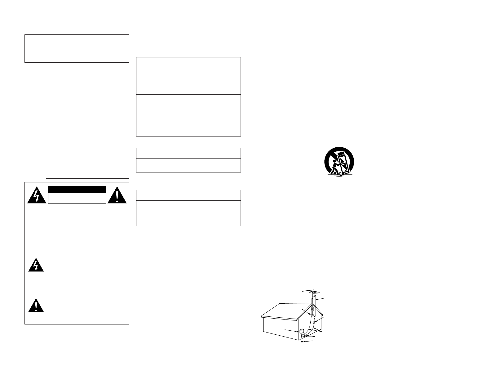
15. Outdoor Antenna Grounding – If an outside antenna or
cable system is connected to the product, be sure the
antenna or cable system is grounded so as to provide
some protection against voltage surges and built-up static
charges. Article 810 of the National Electrical Code,
ANSI/NFPA 70, provides information with regard to proper
grounding of the mast and supporting structure, grounding
of the lead-in wire to an antenna discharge unit, size of
grounding conductors, location of antenna-discharge unit,
connection to grounding electrodes, and requirements for
the grounding electrode. See Figure A.
16. Lightning – For added protection for this product during a
lightning storm, or when it is left unattended and unused
for long periods of time, unplug it from the wall outlet and
disconnect the antenna or cable system. This will prevent
damage to the product due to lightning and power-line
surges.
17. Power Lines – An outside antenna system should not be
located in the vicinity of overhead power lines or other
electric light or power circuits, or where it can fall into such
power lines or circuits. When installing an outside antenna
system, extreme care should be taken to keep from
touching such power lines or circuits as contact with them
might be fatal.
18. Overloading – Do not overload wall outlets, extension
cords, or integral convenience receptacles as this can
result in a risk of fire or electric shock.
19. Object and Liquid Entry – Never push objects of any kind
into this product through openings as they may touch
dangerous voltage points or short-out parts that could
result in a fire or electric shock. Never spill liquid of any
kind on the product.
20. Servicing – Do not attempt to service this product yourself
as opening or removing covers may expose you to
dangerous voltage or other hazards. Refer all servicing to
qualified service personnel.
21. Damage Requiring Service – Unplug this product from the
wall outlet and refer servicing to qualified service
personnel under the following conditions:
a) When the power-supply cord or plug is damaged,
b) If liquid has been spilled, or objects have fallen into the
product,
c) If the product has been exposed to rain or water,
d) If the product does not operate normally by following
the operating instructions. Adjust only those controls
that are covered by the operating instructions as an
improper adjustment of other controls may result in
damage and will often require extensive work by a
qualified technician to restore the product to its normal
operation,
e) If the product has been dropped or damaged in any
way, and
f) When the product exhibits a distinct change in
performance – this indicates a need for service.
22. Replacement Parts – When replacement parts are
required, be sure the service technician has used
replacement parts specified by the manufacturer or have
the same characteristics as the original part. Unauthorized
substitutions may result in fire, electric shock, or other
hazards.
23. Safety Check – Upon completion of any service or repairs
to this product, ask the service technician to perform
safety checks to determine that the product is in proper
operating condition.
24. Wall or Ceiling Mounting – The product should be
mounted to a wall or ceiling only as recommended by the
manufacturer.
25. Heat – The product should be situated away from heat
sources such as radiators, heat registers, stoves, or other
products (including amplifiers) that produce heat.
FIGURE A
EXAMPLE OF ANTENNA GROUNDING
AS PER NATIONAL
ELECTRICAL CODE
ANTENNA
LEAD IN
WIRE
GROUND
CLAMP
ELECTRIC
SERVICE
EQUIPMENT
ANTENNA
DISCHARGE UNIT
(NEC SECTION 810-20)
GROUNDING CONDUCTORS
(NEC SECTION 810-21)
GROUND CLAMPS
POWER SERVICE GROUNDING
ELECTRODE SYSTEM
(NEC ART 250, PART H)
NEC - NATIONAL ELECTRICAL CODE
CAUTION
RISK OF ELECTRIC SHOCK
DO NOT OPEN
Page 3
3
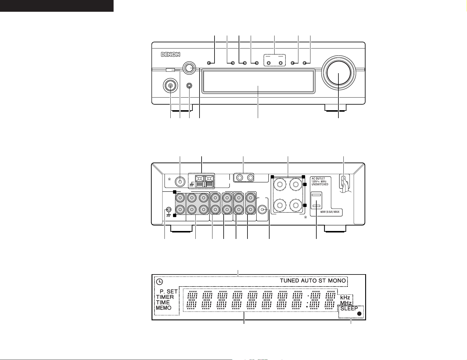
FRONT PANEL
PANNEAU AVANT
PANEL FRONTAL
REAR PANEL
PANNEAU ARRIERE
PANEL TRASERO
PHONES
SYSTEM
VOLUME
ON / STANDBY
AM-FM STEREO RECEIVER DRA-F101
SOURCE
DIRECTBANDUPDOWN
TUNING
MEMORY
/ SET
FUNCTION
TIMERTONE DISPLAY
qwer t y
u
i
o!0
!1
!2!3
SPEAKER SYSTEM
SYSTEM
CONNECTOR
PRE
OUT
SUB
WOOFER
RECPB
MDTAPEINPUTS
RECPBDVD/AUXCDPHONO
1
AM LOOP ANT.
ANTENNA
2
L
+
-
R
SPEAKER IMPEDANCE 4~16
FM COAX.
75
L
R
!4 !5 !6 !6!7 !7 !8 !9
@0
@1@2@3
@4
DISPLAY
AFFICHAGE
VISUALIZADOR
@6 @5
@5
ENGLISHENGLISH FRANCAIS ESPAÑOL
Page 4
4
TABLE OF CONTENTS
z
MAIN FEATURES ………………………………………
4
x
BEFORE USING ………………………………………
5
c
CONNECTING THE ANTENNAS ……………………
5
v
CONNECTIONS ……………………………………
6, 7
b
PART NAMES AND FUNCTIONS …………………
8, 9
n
SYSTEM REMOTE CONTROL …………………
9~11
m
OPERATION ……………………………………
12, 13
,
LISTENING TO RADIO …………………………
13, 14
.
USING THE TIMER ………………………………
15~17
⁄0
SYSTEM FUNCTIONS ………………………………
17
⁄1
TROUBLESHOOTING ………………………………
18
⁄2
SPECIFICATIONS ……………………………………
19
Check that the following parts are included in the package aside from the main unit:
2
ACCESSORIES
q Remote control unit (RC-927) …………………………1
w Batteries R03 (AAA) ……………………………………2
e FM indoor antenna ……………………………………1
r AM loop antenna ……………………………………1
t Operating instructions …………………………………1
y Service station list ……………………………………1
qwer
RC-927
REMOTE CONTROL UNIT
CLEAR
5
5
C
D
S
R
S
M
D
T
A
P
E
C
D
-
R
TUNING
REV.
MODE
Dolby NR
REPEAT
CALL
P
R
O
G
/
D
I
R
E
C
T
RANDOM
BAND
RDS
DIMMER
TIME/
PANEL
TIME EDIT
SYSTEM
POWER
OFF
ON
STOP
PLAY
VO
LUME
/SELECT
SLEEP
MODE
TAPE
FUNCTION
PRESET
+
-
TUNER
CD
MD
TAPE
+
-
1
23
64
7
8
9
10
+10
1. HC-TR output circuit for both subtlety and power
A single push-pull circuit using an HC-TR (high current
transistor) based on the same principles as the UHCMOS used in the POA-S1, DENON’s top grade
monaural power amplifier, achieves both stable a high
current supply and excellent low level signal linearity.
The result is an extremely high level of both subtlety
and power.
2. Strong power circuitry supporting the expressive
abilities of the HC-TR output circuit
The strong power circuitry consisting of high speed
rectifier diodes and large high sound quality block
condensers allow the HC transistor output circuit to be
used to its maximum potential.
3. S.L.D.C.
The DRA-F101 uses an S.L.D.C. (Signal Level Divided
Construction) with the ideal separation of the different
circuits (low level signal circuit, high level signal circuit,
microprocessor circuit, etc.)
4. Source Direct function for improved sound quality
The DRA-F101 is equipped with a source direct
function that bypasses the bass, treble, loudness and
balance control circuits to achieve a simple signal path,
contributing to keeping the sound pure.
5. AM/FM tuner with random 40-station preset
function
6. System remote control unit
The DRA-F101 comes with a system remote control
unit that can be used to control the CD player (DCDF101) (when used system connections only).
7. Low standby power consumption
The power consumption when the power is in the
standby mode is reduced to 1W or less.
1
MAIN FEATURES
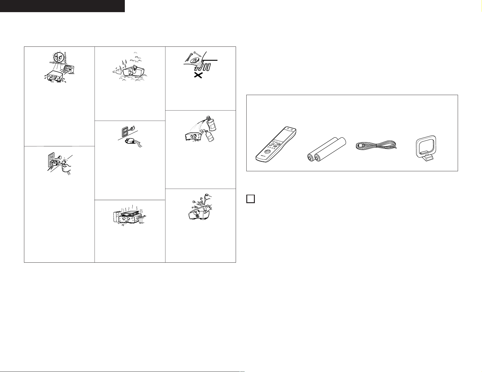
NOTE ON USE / OBSERVATIONS RELATIVES A L’UTILISATION /
NOTAS SOBRE EL USO
• Avoid high temperatures.
Allow for sufficient heat dispersion
when installed on a rack.
• Eviter des températures élevées
Tenir compte d’une dispersion de
chaleur suffisante lors de
l’installation sur une étagère.
•
Evite altas temperaturas
Permite la suficiente dispersión del
calor cuando está instalado en la
consola.
• Handle the power cord carefully.
Hold the plug when unplugging the
cord.
• Manipuler le cordon d’alimentation
avec précaution.
Tenir la prise lors du débranchement
du cordon.
•
Maneje el cordón de energía con
cuidado.
Sostenga el enchufe cuando
desconecte el cordón de energía.
• Keep the set free from moisture,
water, and dust.
• Protéger l’appareil contre l’humidité,
l’eau et la poussière.
•
Mantenga el equipo libre de
humedad, agua y polvo.
• Unplug the power cord when not
using the set for long periods of
time.
• Débrancher le cordon d’alimentation
lorsque l’appareil n’est pas utilisé
pendant de longues périodes.
•
Desconecte el cordón de energía
cuando no utilice el equipo por
mucho tiempo.
• Do not obstruct the ventilation holes.
• Ne pas obstruer les trous d’aération.
•
No obstruya los orificios de
ventilación.
* (For sets with ventilation holes)
• Do not let foreign objects in the set.
• Ne pas laisser des objets étrangers
dans l’appareil.
•
No deje objetos extraños dentro del
equipo.
• Do not let insecticides, benzene, and
thinner come in contact with the set.
• Ne pas mettre en contact des
insecticides, du benzène et un diluant
avec l’appareil.
•
No permita el contacto de
insecticidas, gasolina y diluyentes
con el equipo.
• Never disassemble or modify the set
in any way.
• Ne jamais démonter ou modifier
l’appareil d’une manière ou d’une
autre.
•
Nunca desarme o modifique el
equipo de ninguna manera.
ENGLISH FRANCAIS ESPAÑOL
Page 5
5
ENGLISH
3
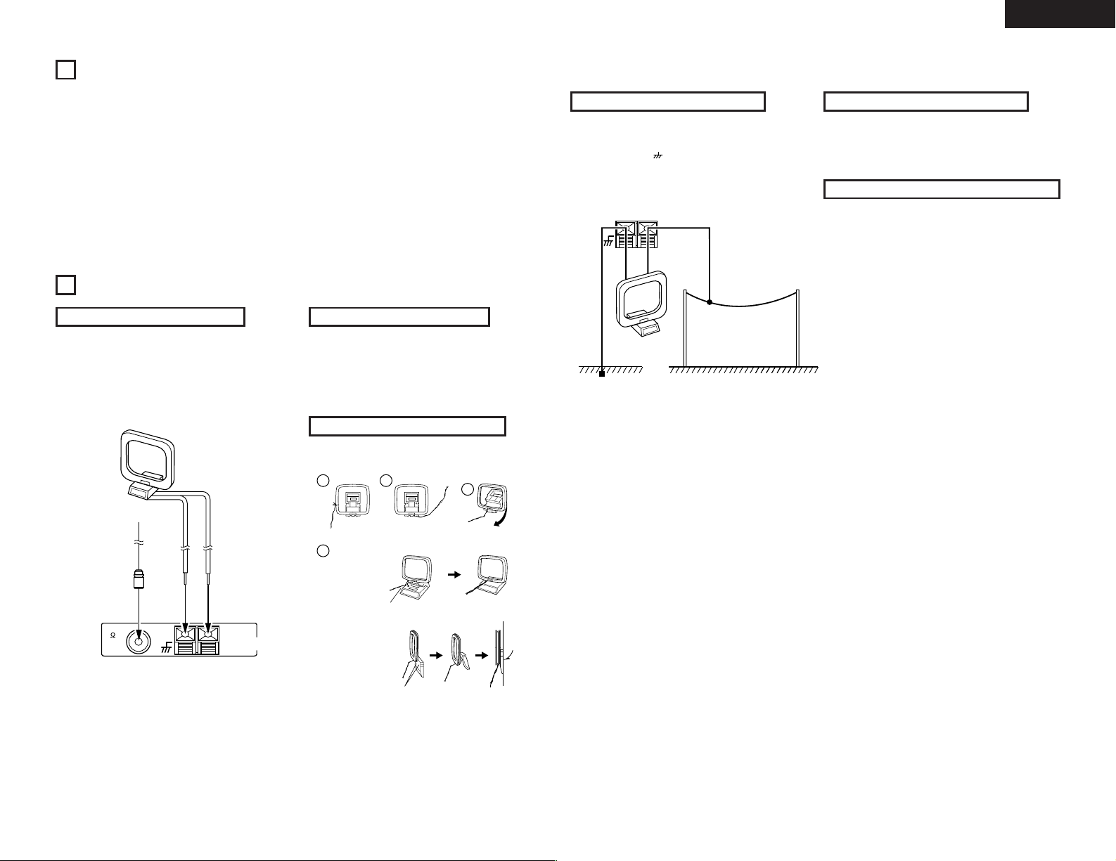
CONNECTING THE ANTENNAS
Installing the FM indoor antenna
Tune in FM station (see page 13), set the antenna so that
distortion and noise is minimal, then secure the tip of the
antenna in this position using tape or a pin.
Installing the AM loop antenna
Tune in an AM station (see page 13) and set the antenna
as far from the system as possible to keep distortion and
noise is minimal. In some cases, it is best to invert the
polarities. AM broadcasts cannot be received well if the
loop antenna is not connected or if it is set close to metal
objects.
AM LOOP ANT.
ANTENNA
FM COAX.
75
FM antenna
AM loop antenna
Installing an AM outdoor antenna
Connect the signal wire from the AM outdoor antenna to
the antenna terminal. Be sure to connect the signal
ground wire to the terminal. Also be sure to connect
the included AM loop antenna.
AM LOOP ANT.
ANTENNA
Signal ground
AM outdoor antenna
Assembling the AM loop antenna
Connect to the AM
antenna terminals.
Bend in the reverse
direction.
Remove the vinyl tie
and take out the
connection line.
Installation hole
Mount on wall, etc.
Mount
a. With the antenna
on top any stable
surface.
b. With the antenna
attached to a wall.
AM loop antenna
Connecting an FM outdoor antenna
If good reception cannot be achieved with the included
FM antenna, use an FM outdoor antenna. Connect an IECtype connector to the coaxial cable and connect the
antenna to the FM COAX (75 Ω/ohms) terminal.
Selecting a place for the FM outdoor antenna
• Set the antenna so that it points towards the broadcast
station’s transmitting antenna. Behind buildings or
mountains, set the antenna in the position at which
reception is best, and also try changing the direction of
the antenna.
• Do not install the antenna under power lines.
Doing so is extremely dangerous, as the power line
could touch the antenna.
• Install the antenna away from roads or train tracks to
avoid noise from cars or trains.
• Do not install the antenna too high, as it may be hit by
lightning.
2
BEFORE USING
Read the following before using the set.
• Before turning on the power
Check again that all connections are correct and that
there are no problems with the connection cords. Be
sure to unplug the power cord before connecting or
disconnecting the connection cords.
• Moving the set
To prevent short-circuits or damage to the connection
cords, always unplug the power cord and disconnect
the connection cords between all other audio
components when moving the set.
• Store this instructions in safe place
After reading, store this instructions along with the
warranty in a safe place. Also fill in the items on the
back paper for your convenience.
• Illustrations in this manual
Note that some of the illustrations used for
explanations in this manual may differ from the actual
set.
1
4
2
3
Page 6
6
ENGLISH
SPEAKER SYSTEM
SYSTEM
CONNECTOR
PRE
OUT
SUB
WOOFER
RECPB
MDTAPEINPUTS
RECPBDVD/AUXCDPHONO
1
AM LOOP ANT.
ANTENNA
2
L
+
-
R
SPEAKER IMPEDANCE 4~16
FM COAX.
75
L
R
RLR
L
R
L
L
R
L
R
L
R
R
L
R
L
R
L
R
L
R
L
DVD
B
R
L
(L)
Subwoofer
(R)
4
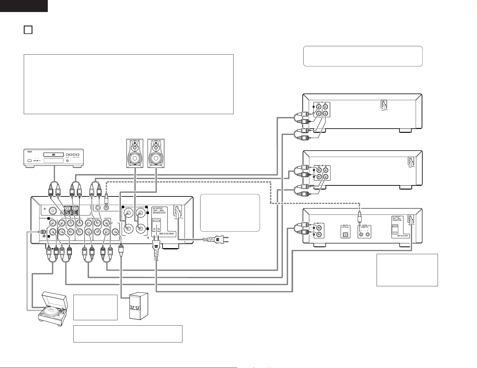
CONNECTIONS
2 When connecting, also refer to the manuals of the other components.
2 When connecting to the DCD-F101, make the system connection shown by dotted line on the diagram below.
2 The DRA-F101 is not equipped with connection cord. Use the connection cord included with the DCD-F101.
NOTE:
• To allow for heat dispersal, do
not place another component
or any other object directly on
top of the DRA-F101.
NOTE:
•
If noise is generated
when the ground wire is
connected, disconnect
the ground wire.
• When making system connection with the DCD-F101, connect the
system cord to the DRA-F101 system connector (either 1 or 2).
(System connection is indicated by dotted line on the diagram.)
• The D-F101 series stereo
receiver (DRA-F101) is
equipped with a clock and timer
function, so be sure to connect
it to a wall power outlet to
which power is supplied
constantly.
Speaker system
MD recorder
Cassette deck
CD player (DCD-F101)
NOTES:
• Do not plug the power cords into the power outlets until all connections have been completed.
• Check the left and right channels and be sure to interconnect them correctly (R to R, L to L).
• Plug in the power cords securely. Incomplete connections will result in noise.
•
Use the AC OUTLET for audio equipment only. Do not use them for hair driers, etc.
• Do not clasp the connection cords together with the power cords or place them near other electric products. Doing so may
result in noise.
• The PHONO input jack is extremely sensitive. A booming sound may be produced from the speakers if the volume is turned
up when no turntable is connected.
• The sound of another component may be heard if no component is connected to the input jacks of the function selected
with the FUNCTION selector.
DVD player
Power plug
AC 120V, 60 Hz
(Plug into a power outlet)
Turntable
(with MM cartridge)
NOTE:
•
This unit cannot be used with MC cartridges directly. Use a head
amplifier or a step-up transformer with MC cartridges.
Page 7
7
ENGLISH
System Operations
• System operations such as the timer playback and auto power on functions can only be used if stereo audio cords
and system cords are connected between all the system components. Be sure to securely connect all the
connection cords between all the units.
• Disconnecting a system cord during system operation may result in malfunction. Be sure to unplug the power
cords before changing the connections.
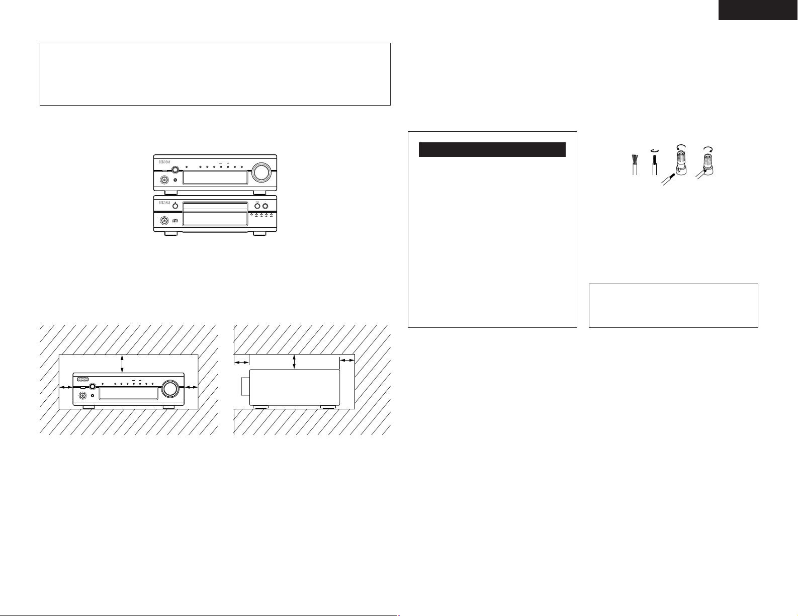
2
Recommended System Installation
• To ensure performance and stability, install the system (D-F101 series) as shown below.
PHONES
SYSTEM
VOLUME
ON / STANDBY
AM-FM STEREO RECEIVER DRA-F101
SOURCE
DIRECT
BANDUPDOWN
TUNING
MEMORY
/ SET
FUNCTION
TIMERTONE DISPLAY
TRACK
ON / STANDBY
COMPACT DISC PLAYER DCD-F101
REPEAT
✽
Do not place another component directly on top of the DRA-F101. To allow for heat dispersal, leave a space of at
least 10 cm above the DRA-F101 so as not to obstruct its ventilation holes.
✽
For stability, do not stack more than three components on top of each other.
(DRA-F101)
(DCD-F101)
Connecting Speaker Systems
2
Speaker impedance
Use speaker systems with an impedance of 4 to
16Ω/ohms.
• Note that using speakers with other impedances will
activate the protector circuit and may result in
damage.
qw e r
The DRA-F101 is equipped with a high
speed protector circuit.
This circuit prevents strong currents
from being generating inside the unit
and damaging internal circuitry if the
speaker cables are not securely
connected to the speaker terminals or if
they are short-circuited. If the protector
circuit is activated, the speaker output is
automatically cut off. If this happens,
turn off the unit’s power, check the
speaker cable connections, then turn the
power back on. The sound will be muted
for several seconds, after which the unit
will operate normally.
Protector Circuit
2
Connecting the speaker cords
q Peal off the coating from the tip of the cord.
w Twist the core wire.
e Turn the speaker terminal counterclockwise to
loosen it.
r Completely insert the core wire, then turn the
terminal clockwise to tighten it.
B Be sure to connect the speaker cords to the terminals
with the same polarities on the speaker and amplifier
( < to <, > to > ).
B When connecting, make sure that the speaker cords’
core wires do not stick out and touch other terminals,
other core wires or the rear panel.
NOTE:
• NEVER touch the speaker terminals while the set is
connected to a power supply. Doing so may result in
electric shock.
For heat dispersal, leave at least 10 cm of space between the top, back and sides of this unit and the wall or
other components.
PHONES
SYSTEM
VOLUME
ON / STANDBY
AM-FM STEREO RECEIVER DRA-F101
SOURCE
DIRECT
BANDUPDOWN
TUNING
MEMORY
/ SET
FUNCTION
TIMERTONE DISPLAY
• Switching the input function when input jacks are
not connected
A clicking noise may be produced if the input function
is switched when nothing is connected to the input
jacks. If this happens, either turn down the VOLUME
control or connect components to the input jacks.
Please be sure to unplug the cord when you leave
home for a vacation.
5 cm
10 cm or more
✽
✽
✽
✽
✽
Page 8

TIME: Use this to set the time.
EVERYDAY: Use this to set the everyday timer.
ONCE: Use this to set the once timer.
• Press this button during in STANDBY mode to
switch ON/OFF (“Saving Energy Mode”) the clock
display.
!3
Tone button (TONE)
• Use this to set the bass, treble and balance level.
(Refer to pages 12, 13.)
• Use this to set the loudness function to on or off.
(Refer to page 13.)
8
ENGLISH
5
PART NAMES AND FUNCTIONS
(1) Front Panel
q
Power operation switch (ON/STANDBY)
• This turns the power for the entire system on and
off.
• Press this once to turn the power on, then press
again to set the power to STANDBY mode.
• The LED color changes as follows, according to
the condition:
During power ON : green
During STANDBY : red
During TIMER STANDBY: orange
✻ The muting mode is set when the main unit’s
power button is pressed and when the standby
mode is canceled from the remote control unit.
The power indicator flashes green when in the
muting mode, then stops flashing and turns green
once the set is in the operational mode.
✻ If the indicator is flashing orange (quickly):
The protective circuit is activated.
If this happens, unplug the power cord to turn the
indicator off, then check the input and output
terminals on the rear panel. Check in particular for
short-circuiting of the speaker cords. Once all
connections have been corrected, plug the power
cord. (Wait for at least 10 seconds after turning
the power off before turning it back on.)
• When the DRA-F101 is connected in a system
with the DCD-F101, its power button works as the
power button for the entire system. When the
DRA-F101’s power turns on, the power of the
DCD-F101 also turns on.
✻ Power is supplied to the DRA-F101 even when
the power is in the standby mode (low power
consumption).
w
REMOTE SENSOR (Remote Control Sensor)
• Point the included remote control unit (RC-927) at
this sensor when operating it.
e
Headphones jack (PHONES)
• Use this jack to listen to the sound over
commercially available headphones.
• When the headphones’ plug is inserted into the
jack, the speaker output is automatically cut off,
so no sound is produced from the speakers.
r
Function dial (FUNCTION)
• Switches the input function. Also used to set the
modes selected with the mode button.
(See pages 12, 13.)
t
Display
Refer to page 9.
y
Volume control dial (VOLUME)
• Use this to adjust the overall volume. (Rotary
Encoder System).
• The volume increases when the control is turned
clockwise (, ), decreases when it is turned
counterclockwise (.).
• The volume increases and decreases in 63 steps
from the minimum (VOLUME 0) to the maximum
(VOLUME MAX).
u
Source direct button (SOURCE DIRECT)
• When pressed and set to the “ON” position, the
tone control (bass, treble, balance and loudness)
circuits are set into default condition.
• When pressed again and set to the “ OFF”
position, the signals pass through the tone control
circuits, so the tone (bass, treble, balance and
loudness) can be adjusted as desired.
i
Band button (BAND)
• Each time this button is pressed, the band and FM
reception mode change as follows.
CLOCK: Indicates the current time.
TIMER STANDBY: Indicates the timer standby
mode. Use the TUNING buttons to set the timer
standby mode on or off (refer to page 16).
• Press this buttons for at least 3 seconds to set the
timer (refer to page 15) or to confirm the timer
contents (refer to page 16).
Each time the TUNING button is pressed, the
display changes as follows:
TIME EVERYDAY ONCE
FUNCTION
TIMER STANDBY
CLOCK
TIME FUNCTION
FM AUTO FM MONO AM
!2
Timer button (TIMER)
• Press this button during power ON mode to
confirm or change the display. Each time this
button is pressed, the display changes as follows:
o
Tuning buttons
(TUNING UP AND DOWN)
• Use these buttons to tune in AM and FM stations.
(TUNING UP/DOWN) (See page 13.)
!0
Memory/set button (MEMORY/SET)
• Use this as the memory button when presetting
AM and FM stations.
• Use this as the set button when setting the time
and timer and when inputting data.
• When the PTY search mode, press this button to
select the type of program.
!1
Display button (DISPLAY)
Each time this button is pressed, the display
changes as follows:
!4
SIGNAL GND (ground) terminal
• Connect the turntable’s ground wire here.
!5
INPUT terminals (INPUTS)
These are input terminals for CD player, turntable,
DVD or other playback components.
!6
TAPE and MD PLAY terminals (PB)
• Playback terminals (PB)
!7
TAPE and MD REC terminals (REC)
• Recording terminals (REC)
• These are output jacks for recording.
• TAPE:
Use these to connect a cassette deck.
• MD:
Use these to connect an MD recorder
!8
PRE OUT terminal (SUB WOOFER)
• Connector jack for subwoofer with built-in
amplifier (super woofer), etc.
!9
AC OUTLET
• When using in combination with the DCD-F101,
connect DCD-F101 to the AC outlet on the
receiver (DRA-F101).
@0
Power cord
• Plug this cord into a wall power outlet.
@1
Speaker terminals
(SPEAKER SYSTEM)
• Use these to connect the speakers.
@2
System connectors
(SYSTEM CONNECTOR 1 and 2)
• When connecting the DCD-F101 in a system,
connect these connectors to system connectors
on DCD-F101.
(Use the system cord included with the DCDF101.)
@3
AM antenna terminal
(ANTENNA TERMINAL AM)
• Connect the AM antenna here.
@4
FM antenna terminal
(ANTENNA TERMINAL FM)
• Connect the FM antenna here.
(2) Rear Panel
NOTE:
• This terminal is designed to reduce noise
when a turntable is connected.
This is not a safety ground.
Page 9
9
ENGLISH
(3) Display [t]
@5
Mode indicators
• These indicate the various modes.
• :
This lights when the timer is set to the standby
mode. It does not light if the current time and
the timer have not been set.
• TIME:
This lights when the display is set to the time
display.
• TIMER:
This lights when the timer is set.
It also lights while the timer is being set.
• TUNED:
This lights when a station is properly tuned in.
• STEREO:
This lights in the AUTO mode when a stereo
broadcast is tuned in.
• MONO:
This lights in the AUTO mode when a monaural
broadcast is tuned in and when the MONO
mode is set with the BAND button.
• AUTO:
This lights when the AUTO mode is set with the
BAND button.
• MEMO:
This flashes when storing AM and FM stations
in the preset memory to indicate that the station
can be stored in the memory.
• SLEEP:
This lights when the sleep timer is activated.
@6
Main display section
•
The function, input program source, etc., are
displayed here.
• During normal operation the input program source
is displayed.
• When the mode button is pressed, the display
switches to show the various functions.
• The reception band, reception frequency, time,
timer setting times, etc., are displayed here.
2 The included remote control unit (RC-927) can be used to perform the main operations of the units in the D-F101
series that are connected with system connections. Other components cannot be operated with this remote control
unit.
Note that some functions may not operate with system remote control units. In this case, use the remote control unit
included with the component.
6
SYSTEM REMOTE CONTROL
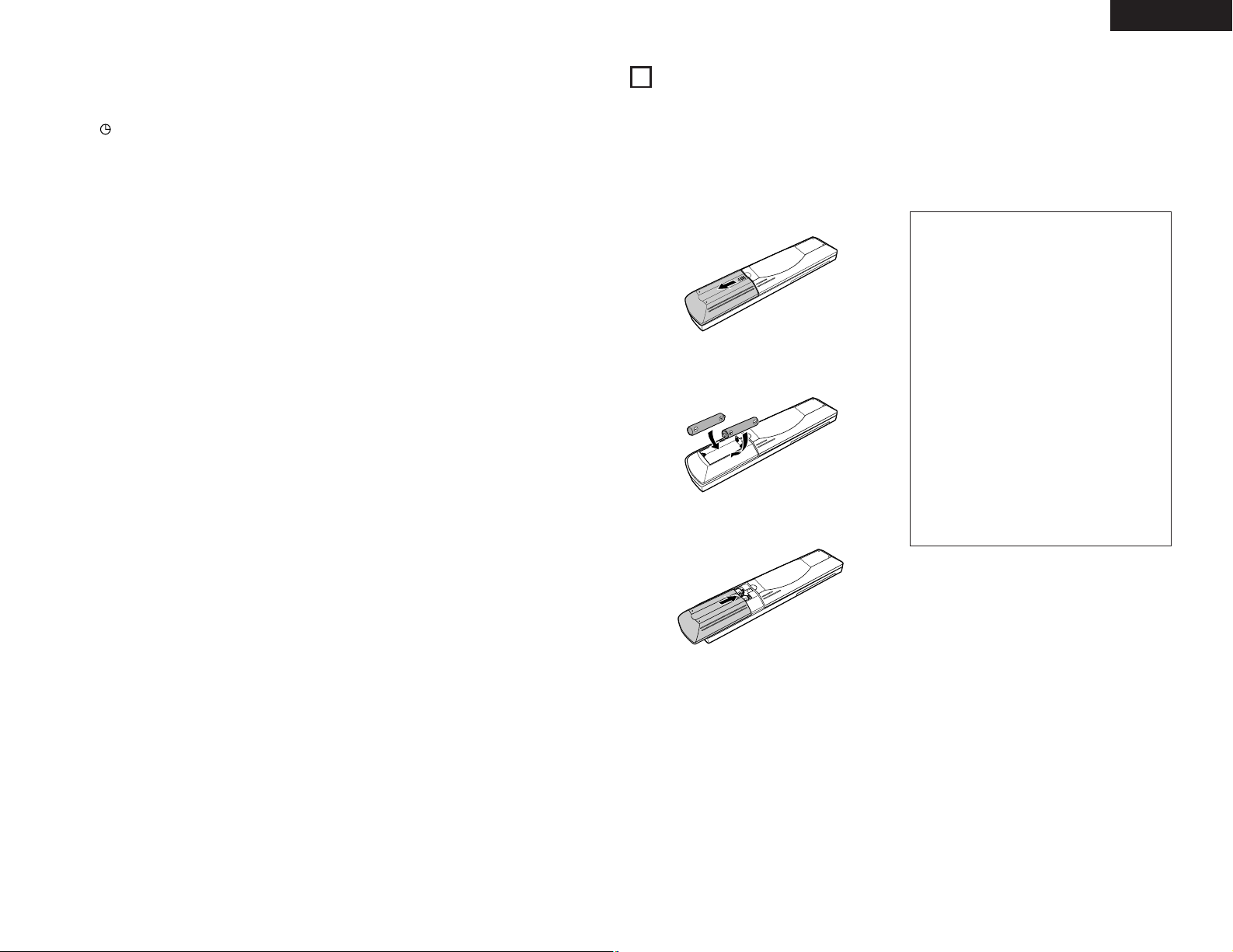
(1) Inserting Batteries
q Remove the remote control unit’s cover.
w Insert two R03 (AAA) batteries into the battery
compartment in the direction indicated by the marks.
e Set the cover back in its original position.
Cautions on Batteries
• Use R03 (AAA) batteries in this remote control unit.
• Replace the batteries with new ones after
approximately 1 year, though this depends on the
frequency with which the remote control unit is
used.
• Replace the batteries with new ones if the unit does
not operate when the remote control unit is
operated from nearby, even if the batteries are less
than a year old.
• Be sure to insert the batteries in the proper
direction, following the “ < ” and “ > ” marks in
the battery compartment.
• To avoid damage or leakage of battery fluid:
• Do not use a new battery with an old one.
• Do not use two different types of batteries.
• Do not short-circuit, take apart, heat or dispose of
batteries in flames.
• Remove the batteries when you do not plan to use
the remote control unit for an extended period of
time.
• If the battery fluid should leak, carefully wipe off the
fluid from the inside of the battery compartment,
then insert new batteries.
Page 10

10
ENGLISH
(2) Using the Remote Control Unit
• Point the remote control unit at the remote sensor on
the main unit as shown on the diagram when operating
it.
(When system connections are made, the remote
control signals for all the system components are
received at the DRA-F101 remote sensor.)
• The remote control unit can be used from a straight
distance of about 7 meters, but this distance will be
shorter if the there is an obstacle in the way or if the
remote control unit is not pointed directly at the remote
sensor.
• Use the remote control unit within a range of 30° to the
left and right of the remote sensor.
PHONES
SYSTEM
V
O
L
U
M
E
ON / STANDBY
A
M
F
M
S
T
E
R
E
O
R
E
C
E
IV
E
R
D
R
A
F
1
0
1
SOURCE
DIRECT
BAND
UP
DOWN
TUNING
MEMORY
/ SET
F
U
N
C
T
IO
N
TIMER
TONE
DISPLAY
R
C
9
2
7
R
E
M
O
T
E
C
O
N
T
R
O
L
U
N
I
T
C
L
E
A
R
5
5
+
1
0
CD
SRS
M
D
T
AP
E
T
U
N
I
N
G
R
E
P
E
A
T
C
A
L
L
P
R
O
G
/
D
IR
E
C
T
R
A
N
D
O
M
B
A
N
D
R
D
S
D
IM
M
E
R
T
I
M
E
/
P
A
N
E
L
T
I
M
E
E
D
IT
S
Y
S
T
E
M
P
O
W
E
R
O
F
F
O
N
S
T
O
P
P
L
A
Y
V
O
L
U
M
E
/S
E
L
E
C
T
S
L
E
E
P
M
O
D
E
T
A
P
E
F
U
N
C
T
IO
N
P
R
E
S
E
T
+
-
T
U
N
E
R
C
D
M
D
T
A
P
E
1
2
3
4
6
7
8
9
+
-
1
0
+
1
0
Approx. 7m/22 feet
30°
30°
NOTES:
• The remote control unit may not work properly if the
remote sensor is exposed to direct sunlight or
strong artificial light or if there is an obstacle
between the remote control unit and the remote
sensor.
• Do not press the buttons on the main unit and the
remote control unit at the same time. Doing so will
result in malfunction.
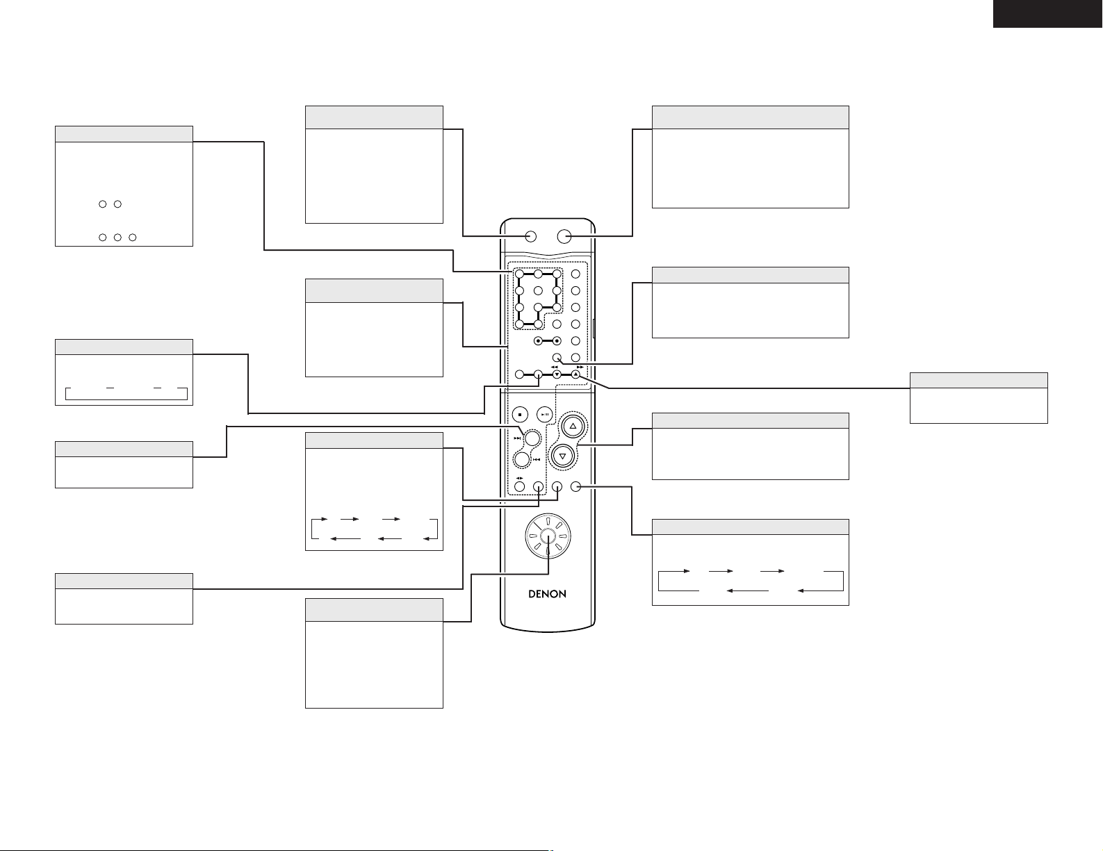
(3) Names and Functions of Remote Control Unit Buttons
2
Opening the remote control unit’s cover
RC-927
REMOTE CONTROL UNIT
CLEAR
5
5
C
D SRS
M
D
TAPECD
-R
TUNING
REV.
MODE
DOLBY
REPEAT
CALL
PROG/
DIRECT
RANDOM
BAND
PTY
RDS
DIMMER
TIME/
PANEL
TIME EDIT
SYSTEM
POWER
OFF ON
STOP
PLAY
VOLUME
/SELECT
SLEEP
MODE
TAPE
FUNCTION
PRESET
+
-
TUNER
CD
MD
TAPE
+
-
1
23
6
4
7
8
9
+10 0
RC-927
REMOTE CONTROL UNIT
CLEAR
5
5
CD SR
S
MDTAPE
TUNING
REPEAT
CALL
PROG/
DIRECT
RANDOM
BAND
PTY
RDS
DIMMER
TIME/
PANEL
TIME EDIT
SYSTEM
POWER
OFF
ON
STOP
PLAY
VOLUME
/SELECT
SLEEP
MODE
TAPE
FUNCTION
PRESET
+
-
TUNER
CD
MD
TAPE
1
23
4
6
7
89
+
-
+10
0
Page 11
11
ENGLISH
RC-927
REMOTE CONTROL UNIT
CLEAR
123
546
789
10
+10
CD SRS
MDTAPE
TUNING
REPEAT
CALL
PROG/
DIRECT
RANDOM
BAND
RDS
DIMMER
TIME/
PANEL
TIME EDIT
SYSTEM
POWER
OFF ON
STOP PLAY
VOLUME
/SELECT
SLEEP MODE
TAPE
FUNCTION
PRESET
+
-
TUNER
CD
MD
TAPE
Models compatible with system remote control
• Receiver : DRA-F101
• CD player : DCD-F101
Press this to set the DRA-F101’s
power to the standby mode.
(When connected in a system
with the D-F101 series, this
button sets the power of the
entire system to the standby
mode.)
Power standby button
(SYSTEM POWER STANDBY)
When connected in a system
with the DCD-F101, these
buttons are used to operate the
DCD-F101.
For operating instructions, refer
to the manuals of the DCD-F101.
D-F101 series
function operation block
Press this to select the function
source to be played.
The function switches in the
following order each time the
button is pressed:
FUNCTION button
Use this to select the function to
be operated with this remote
control unit. Set to TUNER to use
the DRA-F101’s tuner function.
For instructions on operating the
various components, refer to their
respective manuals.
Remote control
function selector switch
When this button is pressed while the DRAF101’s power is in the standby mode, the DRAF101’s power turns on.
(When connected in a system with the D-F101
series, this button turns on the power of the
entire system.)
Power on button
(SYSTEM POWER ON)
• Press Dto increase the volume, Hto decrease
it.
• These buttons are also used to set various
modes.
VOLUME/SELECT buttons
CD
MD TAPE
PHONO
TUNER DVD/AUX
2 Buttons not described here function in the same way as the corresponding buttons on the main unit.
The display becomes darker (in 4 steps) each
time this button is pressed.
Adjust the brightness of the display according to
the brightness of the room.
DIMMER button
✽ The buttons above for which there are no explanations cannot be operated with the DRA-F101.
Press these buttons to recall
preset station.
Examples:
To call the station at preset
number 12:
Press ,
To call the station at preset
number 29:
Press , ,
9
+10
+102+10
Number buttons
Use this button to select the
band.
BAND button (BAND)
FM AUTO FM MONO AM
Use these buttons to recall preset
stations on the tuner.
PRESET button (PRESET)
Press this button to set the sleep
timer
SLEEP button (SLEEP)
Use these buttons to selecting
the station.
TUNING button (•,ª)
The mode switches as follows each time the
button is pressed:
MODE button
BASS
Playback
function source
BALANCE
TREBLE LOUDNESS
Page 12
12
ENGLISH
7
OPERATION
(1) Playback
PHONES
SYSTEM
VOLUME
ON / STANDBY
AM-FM STEREO RECEIVER DRA-F101
SOURCE
DIRECT
BANDUPDOWN
TUNING
MEMORY
/ SET
FUNCTION
TIMERTONE DISPLAY
3 7
2 5
PROG/
DIRECT
SYSTEM
POWER
OFF ON
2
STOP PLAY
VOLUME
/SELECT
SLEEP MODE
TAPE
FUNCTION
PRESET
+
-
TUNER
CD
MD
3
5
3
Either turn the FUNCTION dial on the main unit
or press the remote control unit’s FUNCTION
button to select the function source to be
played.
• The function switches in the order shown
below.
✽
The function switches in the opposite order
when the dial is turned counterclockwise (.).
CD
MD TAPE PHONO
TUNER DVD/AUX
(Main unit) (Remote control unit)
4
Start playback of the selected function source.
• For instructions on operation, refer to the
component’s operating instructions.
5
Adjust the volume.
6
Adjust the BALANCE, BASS, and TREBLE
controls and set the LOUDNESS position to the
desired position.
✽
For instructions on adjusting, see “(3) Setting
the various modes” on page 12, 13.
7
To use the source direct function:
Press the SOURCE DIRECT button to display
“SD ON” .
VOLUME
VOLUME
/SELECT
(Main unit) (Remote control unit)
(Main unit)
1
Check that all connections are correct.
2
Turn on the power.
• The indicator first flashes green, then after
about 6 seconds stops flashing, remaining lit,
indicating that the unit is set to the power on
mode.
(Main unit)
SYSTEM
ON / STANDBY
SYSTEM
POWER
ON
(Remote control unit)
2 Power on/standby mode and function
memory
B
When the remote control unit is used to
turn the DRA-F101’s power on from the
standby mode, the function is set to the
function that was selected when the
power was last set to the standby mode.
(Last memory function)
B
If the function has been cleared from the
memory, the function is set to “CD” when
the DRA-F101’s power is turned on.
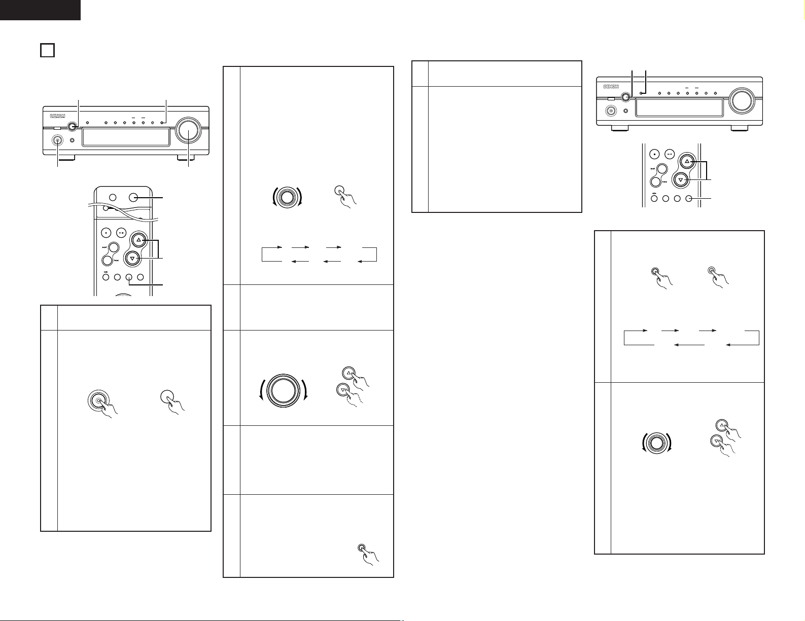
(3) Setting the various modes
[1] Adjusting the bass and treble
PHONES
SYSTEM
VOLUME
ON / STANDBY
AM-FM STEREO RECEIVER DRA-F101
SOURCE
DIRECT
BANDUPDOWN
TUNING
MEMORY
/ SET
FUNCTION
TIMERTONE DISPLAY
2 1
STOP PLAY
VOLUME
/SELECT
SLEEP MODE
TAPE
FUNCTION
PRESET
+
-
1
2
1
2
Press the TONE or MODE button to display the
mode to be adjusted (“BASS” or “TREBLE”).
Either turn the FUNCTION dial on the main unit
or use the remote control unit’s SELECT
buttons.
BASS
Playback
function source
BALANCE
TREBLE LOUDNESS
(Main unit)
MODE
(Remote control unit)
FUNCTION
VOLUME
/SELECT
(Main unit) (Remote control unit)
• To increase the bass or treble:
Turn the dial clockwise (,) or press the
D
button.
To decrease the bass or treble:
Turn the dial counterclockwise (.) or press
the
H
button.
• The bass and treble can be adjusted within
the range of –8 to 0 to +8 in steps of 2. The
response is flat at 0.
• The mode switches as follows each time the
button is pressed:
✽
This cannot be selected when the source
direct mode is set to “ON”.
(decrease) (increase)
(decrease)
(increase)
SOURCE
DIRECT
(2) Recording
1
Follow step 1 to 4 under “(1) Playback”.
2
Start recording on the cassette deck or MD
recorder.
For instructions, refer to the component’s
operating instructions.
• Operating the VOLUME, BALANCE, BASS,
TREBLE and the LOUDNESS controls will not
affect the sound being recorded.
• When the function source is set to “MD”,
recording is performed from the MD recorder
onto the cassette deck. When the function
source is set to “TAPE” , recording is
performed from the cassette deck onto the
MD recorder.
FUNCTION
FUNCTION
TONE
Page 13

13
ENGLISH
8
LISTENING TO RADIO
(1) Tuning
1
Press the power operation switch to turn on the
power.
2
Press the BAND button on the tuner to select
the FM AUTO.
PHONES
SYSTEM
VOLUME
ON / STANDBY
AM-FM STEREO RECEIVER DRA-F101
SOURCE
DIRECT
BANDUPDOWN
TUNING
MEMORY
/ SET
FUNCTION
TIMERTONE DISPLAY
23
1
Example: Tuning in FM 92.50 MHz
(AM stations are tuned in using the same procedure.)
Auto Tuning
• When a program being broadcast in stereo is
received, the “STEREO” indicator lights and the
program is received in stereo.
• If reception is poor and there is much noise in the
stereo signals, press the BAND button to set the FM
MONO mode.
• When one of the TUNING UP/DOWN button is
pressed, the frequency changes in steps of 100 kHz
in the FM band, 10 kHz in the AM band.
• If one of the TUNING UP/DOWN button is held for
over 1 second, the frequency continues to change
when the button is released (auto tuning) and stops
when a station is tuned in. Tuning will not stop at
stations whose reception is poor.
• To stop the auto tuning function, press the TUNING
UP/DOWN button once.
NOTE:
A humming sound may be heard when using a TV
nearby while receiving AM programs. If this happens,
move the system as far from the TV as possible.
3
Use the TUNING UP/DOWN button to tune the
frequency to 92.50.
This lights when a station is tuned in.
[2] Setting the loudness mode
1
2
Press the TONE or MODE button to display
“LOUDNESS”.
Either turn the FUNCTION dial on the main unit
or use the remote control unit’s SELECT
buttons.
TONE
(Main unit)
MODE
(Remote control unit)
FUNCTION
VOLUME
/SELECT
(Main unit) (Remote control unit)
• To set to “ON”:
Turn the dial clockwise (,) or press the
D
button.
To set to “OFF”:
Turn the dial counterclockwise (.) or press
the
H
button.
• The mode switches as shown at the left each
time the button is pressed.
✽
“LOUDNESS” cannot be selected when the
source direct mode is on.
(OFF) (ON)
(ON)
(OFF)
[3] Adjusting the balance
1
2
Press the TONE or MODE button to display
“BALANCE” (Refer to page 12.)
Either turn the FUNCTION dial on the main unit
or use the remote control unit’s SELECT
buttons.
TONE
(Main unit)
MODE
(Remote control unit)
FUNCTION
VOLUME
/SELECT
(Main unit) (Remote
control unit)
• If the volume of the right speaker is low:
Turn the dial clockwise (,) or press the
D
button.
If the volume of the left speaker is low:
Turn the dial counterclockwise (.) or press
the
H
button.
• The balance can be set to “ CENTER” or
adjusted within the range of +1 to +10 in
steps of 1. When set “CENTER” , the
difference between the volume of the left and
right speakers is 0.
✽
“BALANCE” cannot be selected when the
source direct mode is on.
(left channel
volume
adjustment)
(right
channel
volume
adjustment)
(left channel
volume
adjustment)
(right
channel
volume
adjustment)
CLEAR
123
546
789
10
+10
CD SRS
MDTAPE
TUNING
REPEAT
CALL
PROG/
DIRECT
RANDOM
BAND
RDS
DIMMER
TIME/
PANEL
TIME EDIT
SYSTEM
POWER
OFF ON
STOP PLAY
VOLUME
/SELECT
1
3
2
(Main unit)
SYSTEM
ON / STANDBY
SYSTEM
POWER
ON
(Remote control unit)
(Main unit) (Remote control unit)
(Main unit) (Remote control unit)
BAND
BAND
UPDOWN
TUNING
TUNING
Page 14

14
ENGLISH
(2) Presetting AM and FM stations
Example: To preset the currently tuned in FM station at preset number “3”
Procedure
1
Press the MEMORY/SET button.
• The “P.SET” , “MEMO”
indicator flashes.
• Depending on what preset number is
displayed before the button is pressed, the
preset number section flashes as shown
below and the setting standby mode is set.
When “01” to “10” or “0-” is displayed,
“0-” flashes.
When “11” to “20” or “1-” is displayed,
“1-” flashes.
When “21” to “30” or “2-” is displayed,
“2-” flashes.
When “31” to “40” or “3-” is displayed,
“3-” flashes.
✽
To store the station at a different preset
number, use the tuning buttons (TUNING UP
or DOWN) to set the desired preset number.
2
Press the MEMORY/SET button
again while the “MEMO”
indicator is flashing.
• The “MEMO” indicator turns
off and the station is preset.
3
✽
A total of 40 AM and FM stations can be preset
using this procedure.
Presetting
• When a station is preset, both the reception
frequency and reception mode are stored in the
memory.
• If a station is preset at a number where another
station is already preset, the previous station is
erased and the new station is set.
• The preset memory is not erased immediately if the
power supply is cut off momentarily.
• This setting can also be made by pressing the
button instead of pressing “e”.
• To store the station at a different preset number,
use the number buttons and the +10 button on the
system remote control unit (RC-927) to set the
desired preset number.
Examples:
To store the station at preset number 12:
Press ,
To store the station at preset number 29:
Press , ,
9
+10
+102+10
TUNING
PHONES
SYSTEM
VOLUME
ON / STANDBY
AM-FM STEREO RECEIVER DRA-F101
SOURCE
DIRECT
BANDUPDOWN
TUNING
MEMORY
/ SET
FUNCTION
TIMERTONE DISPLAY
1, 3 2
UPDOWN
TUNING
MEMORY
/ SET
MEMORY
/ SET
MEMORY
/ SET
MEMORY
/ SET
3
//
DRA-F101
(this unit)
DRA-F101
(this unit)
(RC-927)
✽
When operating with the
system remote control unit,
first set the remote control
unit’s function selector switch
to “TUNER”.
TUNER
CD
MD
TAPE
(RC-927)
(3) Tuning in Preset Stations
Example: To tune in the station stored at preset
number “3”
✽
When operating with the
system remote control unit,
first set the remote control
unit’s function selector switch
to “TUNER”.
TUNER
CD
MD
TAPE
(RC-927)
Procedure:
• Instead of pressing e, the preset
channel can also be called out by
pressing the < or > button to display
“P.SET 03”.
• To call the station at a different preset number, use
the number buttons and the +10 button on the
system remote control unit (RC-927) to set the
desired preset number.
Examples:
To call the station at preset number 12:
Press ,
To call the station at preset number 29:
Press , ,
9
+10
+102+10
3
While the “MEMO” indicator
is flashing, press the TUNING
UP button three times to
display “P.SET”, “03”.
Page 15

15
ENGLISH
9
USING THE TIMER
(1)
Setting the Current Time (12-hour display)
Example: Setting the current time to 9:30 p.m.
1
Turn on the power.
2
Press the TIMER button for at least
3 seconds.
•“TIME” flashes on the display.
✽
If the time is already set,
“EVERYDAY” is displayed.
Press one of the TUNING buttons
to display “TIME”, then perform
step 3.
7
Press the MEMORY/SET button
at the sound of the chime of a
time service, etc.
•“30” stops flashing, remaining
lit, and the current time is
displayed.
✽
The number changes continuously when one of the
tuning buttons (TUNING UP or DOWN) is pressed.
✽
If the time is already set when step 2, 3 is performed,
both the hours and minutes positions flash.
MEMORY
/ SET
PHONES
SYSTEM
VOLUME
ON / STANDBY
AM-FM STEREO RECEIVER DRA-F101
SOURCE
DIRECT
BANDUPDOWN
TUNING
MEMORY
/ SET
FUNCTION
TIMERTONE DISPLAY
2 3,5,7 4,6
1
SYSTEM
ON / STANDBY
TIMER
5
Press the MEMORY/SET button.
•“9” stops flashing, remaining lit,
and the minutes position starts
flashing.
MEMORY
/ SET
Use the TUNING buttons to
input the minutes (30).
•“30” flashes in the
minutes position.
6
UPDOWN
TUNING
3
Press the MEMORY/SET button.
• The hours position flashes.
MEMORY
/ SET
Use the TUNING buttons
to input the hours (PM 9).
•“9” flashes in the hours
position.
4
UPDOWN
TUNING
(2) Before Setting the Timer
2 Be sure to set the current time. If the current time is not set, the timer standby indicator (“”) will not light and the
timer will not function.
2 Be sure to preset the station before setting the timer. (Refer to “Presetting AM and FM stations” on page 14.)
2 The DRA-F101 is equipped with two types of timers: the everyday time which turns the power on and off at the
same times every day, and the once timer that turns the power on and off only once.
2 Do not change the timer standby mode after the timer is activated (after the timer on time is reached). The timer may
not operate properly.
2 It is not possible to set the timer start and end times to the same time.
2 If the display or operation is not normal, unplug the power cord, then plug it back in while pressing the memory/set
button (MEMORY/SET). This restores the tuner to the initial default values. After doing this, reset the presettings,
current time and timer settings.
2 When setting the timer to operate the CD player do so with a disc loaded and the disc holder closed. The timer will
not operate properly if no disc is loaded or if the disc holder is open.
(3) Setting the Timer
2 The timer function lets you switch the power between
the on and standby modes automatically at the desired
times.
2 When connected in a system with the DCD-F101, the
timer can be used to play a CD.
Example: Using the everyday timer to listen to the
station stored at preset number 3 (FM 98.00 MHz)
from 2:35 p.m. to 2:56 p.m.
1
Turn on the power.
2
Press the TIMER button for at least
3 seconds.
•“EVERYDAY” is displayed.
TIMER
SYSTEM
ON / STANDBY
PHONES
SYSTEM
VOLUME
ON / STANDBY
AM-FM STEREO RECEIVER DRA-F101
SOURCE
DIRECT
BANDUPDOWN
TUNING
MEMORY
/ SET
FUNCTION
TIMERTONE DISPLAY
2 3, 5, 7, 9,11,13,15,17
1,18 4, 6, 8,10,12,14,16
✽
If the time is not set, “TIME” is displayed.
Perform steps 3 to 7 on page 15, then start
the timer setting over.
Press one of the TUNING
buttons to display
“EVERYDAY” or “ONCE”.
UPDOWN
TUNING
3
4
Press the MEMORY/SET button.
• This sets the unit to the timer
setting mode’s function
setting mode.
MEMORY
/ SET
Example: When the everyday timer is
selected
5
Use the TUNING buttons
to switch the function to
“TUNER”.
UPDOWN
TUNING
✽
The function switches as follows each time
the button is pressed:
: When the TUNING UP button is pressed.
: When the TUNING DOWN button is
pressed.
6
Press the MEMORY/SET button.
•“TUNER” is stored in the
memory as the timer function.
MEMORY
/ SET
Use the TUNING buttons
to set preset number 3.
UPDOWN
TUNING
7
8
Press the MEMORY/SET
button.
• The preset station is stored in
the memory and the timer on
time setting mode is set.
“E ” and “oN” appear
alternately in the display in the
steps 8 to 11.
MEMORY
/ SET
<Setting the timer on
time>
Use the tuning buttons to set
the hours position to “PM
2”.
9
UPDOWN
TUNING
Page 16

16
ENGLISH
1 oN/E oN: Both once and everyday timers
are activated. (The mark
lights.)
1_ _/E oN: Only the everyday timer is
activated. (The mark lights.)
1 oN/E_ _: Only the once timer is activated.
(The mark lights.)
1_ _/E_ _: Both timers are canceled. (The
mark turns off.)
10
Press the MEMORY/SET button.
•“PM 2” is stored in the
memory for the hours position.
MEMORY
/ SET
Use the TUNING buttons to
set the minutes position to
“35”.
UPDOWN
TUNING
11
16
Press the MEMORY/SET button.
• The off time is stored in the
memory.
MEMORY
/ SET
Use the TUNING button to
select ”E oN”.
• The “” mark lights.
UPDOWN
TUNING
17
12
Press the MEMORY/SET button.
• The on time is stored in the
memory and the timer off time
setting mode is set.
“E” and “oFF” appear alternately
in the display in the steps 12 to 15.
MEMORY
/ SET
<Setting the timer off
time>
Use the TUNING buttons to
set the hours position to
“PM 2”.
UPDOWN
TUNING
13
14
Press the MEMORY/SET button.
•“PM 2” is stored in the memory
for the hours position.
MEMORY
/ SET
Use the TUNING buttons to
set the minutes position to
“56”.
15
UPDOWN
TUNING
✽
Turning on and off the timer standby ON/OFF
• In TIMER STANDBY mode, each time the TUNING
button is pressed, the setting changes as follows:
18
Turn off the power.
When the DRA-F101 is
connected in a system with
the D-F101 series, press the
power button on the receiver.
• The standby mode is set.
(The power switch indicator
turn orange and display turn
off.)
SYSTEM
ON / STANDBY
• When you set only the everyday timer, the
indication changes between 1_ _/E_ _ and 1_ _/E
oN.
• When you set only the once timer, the indication
changes between 1_ _/E_ _ and 1 oN/E_ _.
• When you complete the setting, the display
automatically returns to the former state after 5
seconds.
• To change the settings of TIMER STANDBY, press
TIMER button to set the unit in TIMER STANDBY
mode first, the use TUNING button to make
changes.
1
1
1
1
1
1
1
1
✽
When the timer start time is reached, the timer
operates.
✽
If “ONCE” is selected in step 3, the once timer
setting mode is selected. Set the timer using the
same procedure. At steps 4 and 8 through 15, “1”
(for once) is displayed instead of “E”.
The once timer is activated when “1 oN” is
displayed at step 17.
NOTES:
• The timer standby indicator (“”) will not light if
the current time is not set. If this happens, set the
current time. (Refer to “Setting the Current Time”
on page 15.)
• When the timer on time is reached while in the
standby mode, operation switches to the operation
set with the timer. (The timer setting has priority.)
• Set the standby mode when using the timer. The
timer may not operate properly if the power is on.
(4) Using the timer
The time and timer functions are incorporated in this unit.
2 Types of timer operations
EVERYDAY TIMER : Use this to turn the power on and standby at the same times every day.
ONCE TIMER : Use this to turn the power on and standby once.
SLEEP TIMER : Use this to set the power to turn standby after 10 to 60 minutes, in steps of 10 minutes (operated
from the remote control unit).
2 Notes on timer settings
• Be sure to set the current time beforehand.
• To listen to a radio program using the timer, be sure to preset the station beforehand. (Refer to “Presetting AM and
FM Stations” on Page 14.)
Timer Settings
Power Failures
Checking the Settings
If the power cord is unplugged or there is a power failure, the settings of the current time and once timer are erased and
the time display will flash. If this happens, reset the current time and the once timer.
Also check the timer and tuner presettings, and reset them if they have been cleared.
To check the timer settings, press the TIMER button for at least 3 seconds to select EVERYDAY or ONCE TIMER.
Next, press the TUNING button to select EVERYDAY or ONCE TIMER, then press MEMORY/SET button repeatedly to
display in order: Timer Start mode, and (when in TUNER mode) the reception band and preset channel number, Timer
On time, Timer Off time, Press the MEMORY/SET button again to return to the current mode display.
Changing the Settings
Repeat the timer setting operation to erase the previous settings and set the new settings.
Note on Setting the Timer
If the time set with the timer is reached while the system power is on, the operation switches to the operation set by
the timer.
Page 17
17
ENGLISH
(5) Timer function
(when connected in a system with the DCD-F101)
2 The power can be set to turn on and off at a specific time or at the same time everyday, in any modes: tuner
(“TUNER”), CD player (“CD”).
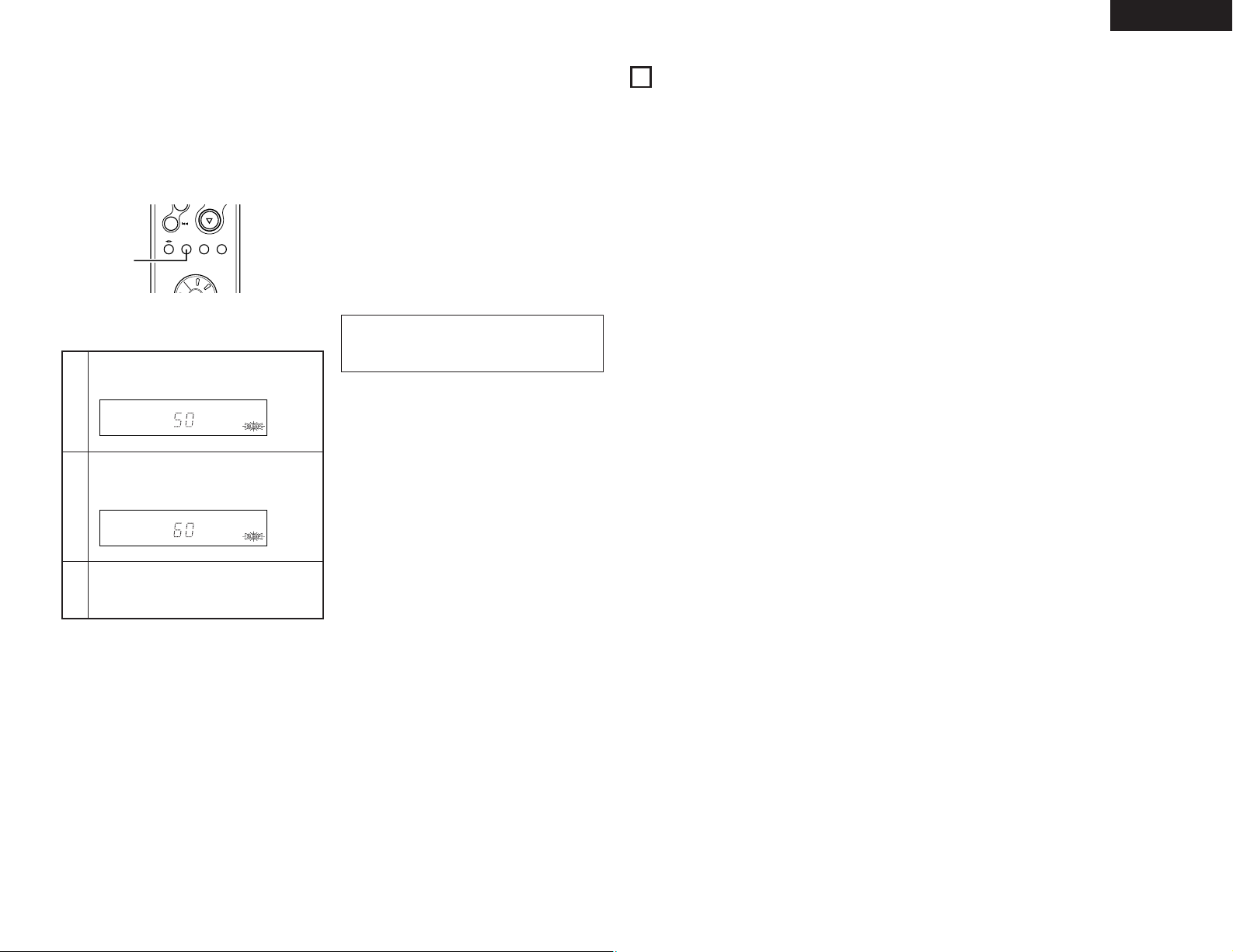
1
Press the SLEEP button.
2
Press the SLEEP button again while the
”SLEEP” indicator is flashing.
Example: To turn the power off after 50 minutes.
(This operation is only possible from the remote
control unit (RC-927).)
3
The previous display reappears after 5 seconds.
The “SLEEP” indicator remains lit, indicating
that the sleep timer is functioning.
Cancelling the Sleep Timer
Press the SLEEP button repeatedly until the “SLEEP”
indicator turns off.
The sleep timer is also canceled if the power operation
switch or the power operation switch on the remote
control unit is pressed, turning the system power off.
NOTE:
If a several timer operations are set at once, the sleep
timer has priority.
• The time is reset to “60” (60 minutes) if the SLEEP
button is pressed again while the sleep timer is
functioning.
SLEEP MODE
TAPE
FUNCTION
+
-
TUNER
CD
MD
TAPE
1,2
RC-927
(system remote
control unit)
(6) Setting the Sleep Timer
2 With this function, the power can be set to turn off after 10 to 60 minutes, in steps of 10 minutes, using the remote
control unit.
10
SYSTEM FUNCTIONS
2 Operation is even easier when the DCD-F101 is connected to the DRA-F101 with system connection. (For
instructions on connections, refer to “CONNECTIONS” on page 6, 7.)
2 All the system function signals for operating the DCD-F101 are output from the DRA-F101, so be sure to connect the
DRA-F101 when making system connection.
2 The system functions will only work when the DCD-F101 is connected. They will not work with other components.
2 When system connections are made, the system functions described below can be used.
(1) The system remote control unit (RC-927) included with the DRA-F101 can be used to perform the main
operations on the DCD-F101.
(2) The remote control signals of the DCD-F101 are received by the DRA-F101’s remote sensor.
(3) Auto function selection:
The function automatically switches when the PLAY/PAUSE button (
1 3
) on the DCD-F101, is pressed, and
playback begins.
(4) Timer functions:
The timer functions on the stereo receiver (DRA-F101) can be used to start playback at set times. The sleep timer
can also be used.
2 For instructions on the various operations, refer to the components’ operating instructions.
Page 18

18
ENGLISH
11
TROUBLESHOOTING
1. Are all connections proper ?
2. Is the set being operated as described in the operating instructions ?
3. Are the speakers and input components being operated properly ?
If the set does not seem to be operating properly, check the points listed below. If these points do not apply, the set
may be damaged. Turn off the power immediately and contact your store of purchase.
Symptom Cause Remedy page
POWER LED does not
light and no sound is
produced when POWER
switch is turned on.
• Power supply cord is not connected. • Check that the cord is plugged in. 6, 8, 12
POWER LED lights but no
sound is produced.
• Speaker cords not properly
connected.
• INPUT SELECTOR not set to proper
position.
• VOLUME control turned down.
• Connect securely.
• Set to the proper position.
• Set to an appropriate level.
6
12
12
Sound is not produced
from one side only.
• Speaker cords not properly connected.
• Input cords not properly connected.
• Left/right balance improperly
adjusted.
• Connect securely.
• Connect securely.
• Adjust the BALANCE control.
6
6
13
Positions of instruments
inverted for stereo sources.
• Left and right speakers or input
cords inverted.
• Check the left/right connections. 6
Hissing noise is heard
when an FM station is
tuned in.
• Is the antenna cable properly
connected?
• Is there interference from an
electronic device equipped with a
microprocessor, or is the signal of
the FM station weak?
• Connect the antenna cable properly.
• Change the position of the
equipment or change the position or
direction of the connection cords and
antenna.
• Connect an outdoor antenna.
5
5, 6, 7
5
Scratchy or hissing noise
is heard when an AM
station is tuned in.
• Is there interference from a TV set,
or interference from another
broadcast station?
• Turn off the TV.
• Change the position or direction of
the AM antenna.
• Connect an outdoor antenna.
—
5
5
Humming noise is heard
when an AM station is
tuned in.
• Is the signal carried over the power
cord being modulated by the power
supply frequency?
• Insert the power plug in the opposite
direction.
• Connect an outdoor antenna.
—
5
Check the following before assuming there is a problem with the set.
Symptom Cause Remedy page
Booming sound produced
when playing records.
• Turntable’ s ground wire not
connected.
• Input cords not properly connected
to PHONO terminals.
• Influence from a TV or other
electrical device near the turntable.
• Connect securely.
• Connect securely.
• Change the position of installation.
6
6
—
Howling produced when
volume is turned up while
playing records.
• Turntable and speaker systems are
too close.
• Floor is soft and vibrates easily.
• Move speaker systems as far away
as possible.
• Use cushions to absorb the
vibrations transmitted from the floor
to the speakers. If the turntable does
not include insulators, use audio
insulators, available in stores.
—
—
Sound is distorted.
This unit does not operate
properly when remote
control unit is used.
• Stylus pressure is too light.
• Dirt on tip of stylus.
• Defective cartridge.
• Batteries dead.
• Remote control unit too far from this
unit.
• Obstacle between this unit and
remote control unit.
• Different button is being pressed.
• < and > ends of battery inserted in
reverse.
• Apply proper pressure.
• Check the tip of the stylus.
• Replace the cartridge.
• Replace with new batteries.
• Move closer.
• Remove obstacle.
• Press the proper button.
• Insert batteries properly.
—
—
—
9
10
10
10
9
Page 19

19
ENGLISH
12
SPECIFICATIONS
2 POWER AMPLIFIER SECTION
Rated Output Power: 35 W + 35 W (4 Ω/ohms, 1 kHz, T.H.D. 0.7%)
Output terminals: 4 to 16Ω/ohms
• PRE AMPLIFIER SECTION
Input Sensitivity/
Input Impedance:
PHONO: 2.5 mV/47 kΩ/kohms
CD, DVD/AUX,
TAPE, MD: 300 mV/47 kΩ/kohms
RIAA Deviation: PHONO: 20 Hz to 20 kHz ±0.5 dB
• OVERALL CHARACTERISTICS
SN Ratio (IHF A Network): PHONO: 80 dB (at 5 mV input) (input terminals short-circuited)
CD, DVD/AUX,
TAPE, MD: 90 dB (SOURCE DIRECT: ON)
Frequency Response: 5 Hz to 80 kHz : +0.5, –3 dB (SOURCE DIRECT: ON)
Tone Control Adjustable Range: BASS: 100 Hz ±8 dB
TREBLE: 10 kHz ±8 dB
LOUDNESS: 100 Hz +8 dB
10 kHz +6 dB
2 TUNER SECTION
Reception frequency range: FM : 87.5 MHz ~ 108.0 MHz
AM : 520 kHz ~ 1710 kHz
Practical sensitivity: FM : 1.2 µV/75 Ω/ohms (12.8 dBf)
AM : 18 µV
FM stereo isolation: 40 dB (1 kHz)
FM S/N ratio: Monaural: 74 dB Stereo: 70 dB
FM harmonic distortion: Monaural: 0.3% Stereo: 0.4%
2 CLOCK/TIMER SECTION
Clock system: Power source frequency synchronization system
Clock precision (per month): ±30 seconds
Timer functions: Everyday timer (1 setting)
Once timer (1 setting)
Sleep timer (maximum 60 min.)
• OTHERS
Power Supply: AC 120 V, 60 Hz
Power Consumption: 85 W
(Approx. 1W in standby mode)
Dimensions: 250 (W) X 81.5 (H) X 285 (D) mm (9-27/32” x 3-13/64” x 11-7/32”)
Mass: 3.5 kg (7 lbs 11 oz)
• REMOTE CONTROL UNIT (RC-927)
Remote control system: Infrared pulse system
Power supply: 3 V DC, Two size R03 (“AAA”)
dry cell batteries
External dimensions: 48 (W) X 210 (H) X 29 (D) mm (1-57/64” x 8-19/64” x 1-9/64”)
Mass: 120 g (4.2 oz)
(including batteries)
• For improvement purposes, specifications and functions are subject to change without advanced notice.
Page 20

36
ESPAÑOL
CONTENDIO
z
CARACTERÍSTICAS ………………………………… 36
x
ANTES DE UTILIZAR EL APALATO………………… 36
c
CONEXIÓN DE LAS ANTENAS …………………… 37
v
CONEXIONES …………………………………… 38, 39
b
NOMBRE Y FUNCIÓN DE LAS PARTES ……… 40, 41
n
CONTROL REMOTO DEL SISTEMA ………… 41~43
m
OPERACIÓN ……………………………………… 44, 45
,
AUDICIÓN DE RADIO ………………………… 45, 46
.
USO DEL TEMPORIZADOR
……………………… 47~49
⁄0
FUNCIONES DEL SISTEMA ………………………… 49
⁄1
LOCALIZACIÓN Y SOLUCIÓN DE PROBLEMAS … 50
⁄2
ESPECIFICACIONES ………………………………… 51
Compruebe que la unidad principal va acompañada de las piezas siguientes:
2 ACCESORIOS
q Mando a distancia (RC-927) …………………………1
w Pilas R03/AAA …………………………………………2
e Antena interior de FM …………………………………1
r Antena AM de cuadro …………………………………1
t Instrucciones de funcionamiento ……………………1
y Lista de servicios técnicos ……………………………1
qwer
RC-92
7
REM
OTE CONTROL UNIT
CLEAR
5
5
C
D
S
R
S
M
D
T
A
P
E
C
D
-
R
TUNING
REV.
MODE
Dolby NR
REPEAT
CALL
P
R
O
G
/
D
IR
E
C
T
RANDOM
BAND
RDS
DIMMER
TIME/
PANEL
TIME EDIT
SYSTEM
POWER
OFF
ON
STOP
PLAY
VOLUM
E
/SELECT
SLEEP
MODE
TAPE
FUNCTION
PRESET
+
-
TUNER
CD
MD
TAPE
+
-
1
23
64
7
8
9
10
+10
1. Circuito de salida HC-TR para conseguir tanto
sutileza como alimentación
Un circuito único push-pull mediante un transistor de
corriente alta (HC-TR) basado en los mismos principios
que el UHC-MOS utilizado en el POA-S1, el
amplificador de potencia monoaural de la gama más
alta de DENON, alcanza de manera estable un alto
suministro de corriente y una linealidad de señal de
nivel bajo excelente. El resultado es un nivel
extremadamente alto tanto de sutileza como de
potencia.
2. Conjunto de circuitos de gran potencia que admite
las capacidades expresivas del circuito de salida
HC-TR.
La conjunto de circuitos de gran potencia que consta
de diodos de rectificador de alta velocidad y
condensadores de bloques de gran calidad de sonido
permiten al circuito de salida del transistor HC utilizarse
a su máximo potencial.
3. S.L.D.C.
El DRA-F101 utiliza un S.L.D.C. (construcción dividida
de nivel de señal) con la separación ideal de los
diferentes circuitos (circuito de señal de nivel bajo,
circuito de señal de nivel alto, circuito de
microprocesador, etc).
4. Función de fuente directa para una calidad de
sonido mejorada
El DRA-F101 está equipado con una función de fuente
directa que se deriva por los circuitos de control de
graves, agudos, volumen y balance para conseguir una
ruta de señal simple que contribuye a conseguir un
sonido más puro.
5. Sintonizador AM/FM con función de preselección
aleatoria de 40 emisoras
6. Unidad de mando a distancia del sistema
El DRA-F101 viene con una unidad de mando a
distancia del sistema que se puede utilizar para
controlar el reproductor de CD (DCD-F101) (cuando se
utilicen conexiones del sistema solamente).
7. Consumo bajo de energía en el modo standby
El consumo de energía cuando la alimentación está en
el modo standby o se reduce a 1W o menos.
1
CARACTERÍSTICAS
2
ANTES DE UTILIZAR EL APALATO
Antes de usar este equipo preste atención a las
siguientes indicaciones:
• Mover el equipo
Para evitar cortocircuitos o daños en los cables de
conexión, cuando quiera mover el equipo, antes de
hacerlo desenchufe siempre el cable de alimentación y
desconecte los cables de conexión entre todos los
demás componentes de audio.
• Antes de encender el interruptor de alimentación
Compruebe de nuevo que todas las conexiones están
correctamente hechas y que los cables no presentan
problemas. Sitúe siempre el interruptor de alimentación
en la posición de espera antes de conectar o
desconectar los cables.de conexión.
• Conserve estas instrucciones en lugar seguro.
Después de leerlas, guarde estas instrucciones en
lugar seguro, junto con la garantía.
• Se advierte que las ilustraciones que figuran en
estas instrucciones pueden diferir de las del equipo
real por motivos de explicación.
Page 21

37
ESPAÑOL
3
CONEXIÓN DE LAS ANTENAS
Instalación de la antena de interior de FM
Sintonice una emisora de FM (consulte la página 45),
coloque la antena de forma que la distorsión y los ruidos
sean mínimos y, a continuación, asegure el extremo de la
antena en esta posición mediante cinta o una pinza.
Instalación de la antena de cuadro de AM
Sintonice una emisora de AM (consulte la página 45) e
instale la antena lo más alejado posible del sistema para
que la distorsión y los ruidos sean mínimos. En ciertos
casos, resulta conveniente invertir las polaridades. Las
emisiones de AM no podrán recibirse óptimamente si la
antena de cuadro no se conecta o si se coloca cerca de
objetos metálicos.
Conexión de una antena de exterior de FM
Si no puede conseguir una buena recepción mediante la
antena de FM incluida, utilice una antena exterior FM.
Conecte un conector IEC al cable coaxial y conecte la
antena a la terminal FM COAX (75 Ω/ohmios).
Selección de un lugar donde colocar la
antena de exterior de FM
• Coloque la antena de forma que quede orientada hacia
la antena de transmisión de la emisora. Si se encuentra
detrás de edificios o de montañas, coloque la antena en
la posición en la que la recepción sea de mejor calidad.
Igualmente, cambie la orientación de la antena.
• No instale la antena debajo de redes de suministro
eléctrico.
Si hace esto correrá un grave peligro, ya que la línea de
alto voltaje podría tocar la antena.
• Instale la antena lejos de carreteras o vías ferreas para
evitar el ruido proveniente de coches o trenes.
• No instale la antena a demasiada altura, ya que podría
ser alcanzada por un rayo.
AM LOOP ANT.
ANTENNA
FM COAX.
75
Antena de FM
Antena de cuadrode AM
Instalación de una antena de exterior de AM
Conecte el cable de señal de la antena de exterior de AM
al terminal de antena. Asegúrese de conectar el cable a
tierra de señal al terminal . Asegúrese también de
conectar la antena de cuadro de AM incluida.
AM LOOP ANT.
ANTENNA
Tierra de señal
Antena de exterior de AM
Montaje de la antena de cuadro de AM
Conecte a los terminales
de antena AM.
Doblar en la
dirección inversa
Ouitar el recubrimiento
de vinilo quitar la linea
de conexión.
Instalación en la
pared, etc.
Perforación
a. Con la antena
sobre cualquier
superficie
estable.
b. Con la antena fija
a la pared.
Antena de cuadro AM
1
4
2
3
Page 22

38
ESPAÑOL
SPEAKER SYSTEM
SYSTEM
CONNECTOR
PRE
OUT
SUB
WOOFER
RECPB
MDTAPEINPUTS
RECPBDVD/AUXCDPHONO
1
AM LOOP ANT.
ANTENNA
2
L
+
-
R
SPEAKER IMPEDANCE 4~16
FM COAX.
75
L
R
RLR
L
R
L
L
R
L
R
L
R
R
L
R
L
R
L
R
L
R
L
DVD
B
R
L
(L)
Subwoofer
(R)
4
CONEXIONES
2 Cuando se efectúe una conexión, consulte también los manuales de otros componentes.
2 Cuando se efectúe una conexión al DCD-F101, efectúe las conexiones del sistema que se muestran en las líneas punteadas
que figuran en el diagrama siguiente.
2 El DRA-F101 no está equipado con el cable de conexión. Utilice el cable de conexión incluido con el DCD-F101.
NOTA:
• Para permitir la dispersió n del
calor, no coloque otro componente
u otro objeto directamente en la
parte superior del DRA-F101.
NOTA:
•
Conecte el cable de
tierra, pero
desconéctelo si se
produce zumbido o
algún otro ruido.
• Cuando efectúe conexiones del sistema con el DCD-F101, conecte
el cable del sistema al conector del sistema DRA-F101 (el 1 o el 2).
(La conexión del sistema se indican mediante la línea punteada en el
diagrama).
• El receptor estéreo de la serie D-F101
(DRA-F101) está equipado con una
función de reloj y temporizador, por
tal motivo asegúrese de conectarlo a
un tomacorriente de pared al cual se
suministre alimentación
constantemente.
Systema de altavoces
Magnetófono de cassettes
Grabador MD
Reproductor CD (DCD-F101)
NOTAS:
• No conecte el cable de alimentación antes de haber completado todas las demás conexiones.
• Asegúrese de conectar correctamente los canales izquierdo y derecho (izquierdo con izquierdo, y derecho con derecho).
• Inserte las clavijas firmemente. Las conexiones poco seguras pueden causar generación de ruido.
• Utilice tomas de CA para equipo de audio solamente. No las utilice para secadores de pelo, etc.
• Tenga presente que el unir los cables con clavijas de espiga a los cables de alimentación o el colocarlos cerca de un
transformador de potencia, podrá causar zumbido u otros ruidos.
• Los terminales de entrada PHONO son de una sensibilidad extremadamente alta, por lo que no debe subir el volumen
cuando las clavijas de conexión no estén conectadas. De hacerlo, se puede provocar una inducción de zumbido (explosión) u
otro ruido e n los altavoces.
• Podría escucharse el sonido de otro componente, si no hay ningún componente conectado a las clavijas de entrada de la
función seleccionada en el selector FUNCTION (función).
Reproductor DVD
Enchufe de corriente
CA 120 V, 60 Hz
(Enchufe a una toma de alimentación)
Reproductor de discos
(cápsula MM)
NOTA:
Esta unidad no puede emplearse con cápsulas MC directamente. Al usar
cápsulas MC, utilice un amplificador principal o un transformador elevador.
Page 23

39
Para facilitar la difusión del calor, deje, como mínimo, una distancia de 10 cm entre la parte superior, la parte
posterior y los lados de este equipo y la pared u otros componentes.
PHONES
SYSTEM
VOLUME
ON / STANDBY
AM-FM STEREO RECEIVER DRA-F101
SOURCE
DIRECT
BANDUPDOWN
TUNING
MEMORY
/ SET
FUNCTION
TIMERTONE DISPLAY
• Activar la función de entrada cuando las tomas de
entrada no están conectadas
Si la función de entrada se activa cuando en las tomas
de entrada no hay nada conectado, puede producirse
un ruido de chasquido. Si ocurre esto, gire el mando de
volumen MASTER VOLUME para bajarlo o conecte los
componentes en las tomas de entrada.
Rogamos se asegure de desenchufar el cable cuando
se vaya de vacaciones.
5 cm
10 cm o más
✽
✽
✽
✽
✽
Operaciones del sistema
• Las operaciones del sistema como las funciones de reproducción con temporizador y de conexión automática sólo
pueden utilizarse si están conectados los cables de audio y del sistema entre todos los componentes del sistema.
Asegúrese de conectar de manera segura todos los cables de conexión entre todas las unidades.
• La desconexión de un cable del sistema durante el funcionamiento del sistema podría provocar un funcionamiento
incorrecto. Asegúrese de desenchufar los cables antes de cambiar las conexiones.
2
Instalación recomendada del sistema
• Para garantizar un buen rendimiento y una buena estabilidad, instale el sistema (serie D-F101) como se muestra a
continuación.
✽
No coloque otro componente directamente en la parte superior del DRA-F101. Para permitir la dispersión del calor,
deje un espacio de al menos 10 cm por encima del DRA-F101, para que no se obstruyan los orificios de ventilación.
✽
Para una mejor estabilidad, no apile más de tres componentes encima de otro.
Conexión del sistema de altavoces
2
Impedancia del altavoz
Utilice los sistemas de altavoces con una impedancia
de 4 a 16Ω/ohmios.
• Tenga en cuenta que si se utilizan los altavoces con
otra impedancia, se activará el circuito protector y
podrían ocasionarse daños.
qw e r
Este equipo está provisto de un circuito
de protección de alta velocidad. Este
circuito protege la circuitería interna
contra daños causados por grandes
flujos de corriente cuando la conexión de
los terminales de altavoces es
incompleta o cuando se genera una
salida por causa de un cortocircuito. El
circuito de protección interrumpe la
salida de sonido por los altavoces.
Cuando esto suceda, asegúrese de
desconectar la alimentación al equipo y
de revisar las conexiones de los
altavoces. Luego, vuelva a conectar la
alimentación. Despué s de algunos
segundos de silenciamiento, el equipo
volverá a funcionar normalmente.
Circuito de protección
2
Conexión de los cables de altavoz
q Pele el extremo del cable.
w Retuerza los hilos.
e Gire el terminal de altavoz en sentido contrario a las
agujas del reloj para aflojarlo.
r Inserte totalmente los hilos, luego gire el terminal
en el sentido de las agujas del reloj para apretarlo.
B Asegúrese de conectar los cables entre los terminales
de altavoz (< a <, > a > ). De no hacerlo, el sonido
central resultará ébil y la posición de los distintos
instrumentos no será clara, disminuyendo el efecto
estéreo.
B Al conectar los altavoces, asegúrese de que los hilos no
se salen de los terminales y tocan en otros terminales o
en el panel trasero.
NOTA:
• NUNCA toque los terminales de altavoces cuando la
alimentación esté conectada.
De lo contrario, usted podrá sufrir una descarga
eléctrica.
PHONES
SYSTEM
VOLUME
ON / STANDBY
AM-FM STEREO RECEIVER DRA-F101
SOURCE
DIRECT
BANDUPDOWN
TUNING
MEMORY
/ SET
FUNCTION
TIMERTONE DISPLAY
TRACK
ON / STANDBY
COMPACT DISC PLAYER DCD-F101
REPEAT
(DRA-F101)
(DCD-F101)
ESPAÑOL
Page 24

40
ESPAÑOL
5
NOMBRE Y FUNCIÓN DE LAS PARTES
(1) Panel Frontal
r
Función dial (FUNCTION)
• Cambia la función de entrada. También se utiliza para
ajustar los modos seleccionados con el botón de
modo. (Consulte las páginas 44 a 45.)
t
Pantalla
Consulte la página 41.
y
Control de volumen (VOLUME)
• Utilícelo para ajustar el volumen global. (Sistema
decodificador giratorio)
• El volumen aumenta al girar el control en el
sentido de las agujas del reloj (,) y disminuye al
girarlo en sentido contrario a las agujas del reloj
(.).
• El volumen aumenta y disminuye en 70
gradaciones, desde el mínimo (VOLUME 0) hasta
el máximo (VOLUME MAX).
u
Interruptor de Emisión Directa
(SOURCE DIRECT)
• Cuando se pulsa y se ajusta a la posición “ON”,
los circuitos del control del tono (grave, agudo,
balance y ruido) se ajustan a la condición de por
defecto.
• Al ser ajustado a la posición ON, los controles
antes mencionados son omitidos y las señales
ingresan directamente al circuito del control de
volumen, lográndose una alta calidad de sonido.
i
Botón banda (BAND)
•
Cada vez que presione este botón, la banda y el modo
recepción de FM cambiarán de la siguiente forma:
FM AUTO FM MONO AM
o
Botones de sintonización
(TUNING UP Y DOWN)
• Utilice estos botones para sintonizar emisoras de
AM y FM.
(TUNING UP/DOWN) (Consulte la página 45).
!0
Botónmemoria/ajuste (MEMORY/SET)
• Utilí celo como el botón de memoria cuando
preajuste emisores AM y FM.
• Utilícelo como el botón de ajuste cuando ajuste la
hora y el temporizador y cuando introduzca datos.
• Cuando esté en el modo de búsqueda PTY, pulse
este botón para seleccionar el tipo de programa.
!1
Botón Visualización (DISPLAY)
Cada vez que pulse este botón, la pantalla
mostrará el mensaje siguiente:
!2
Botón del temporizador (TIMER)
• Pulse este botón durante el modo de alimentación
activo ON para confirmar o cambiar la pantalla.
Cada vez que pulse este botón, la pantalla
mostrará el mensaje siguiente:
!4
Terminal SIGNAL GND (tierra)
• Connect the turntable’s ground wire here.
!5
Terminales de entrada (INPUTS)
Son los terminales de entrada para el reproductor de
CD, la mesa de mezclas, el sintonizador, el DVD u
otros componentes de reproducción.
!6
Terminales TAPE y MD PLAY (PB)
• Terminales de reproducción (PB)
!7
Terminales TAPE y MD REC (REC)
• Terminales de grabación (REC)
• Son las clavijas de salida para grabación.
• TAPE:
Utilícelas para conectar una platina de casete.
• MD:
Utilícelas para conectar un grabador MD.
!8
Terminal PRE OUT (SUB WOOFER)
• Conector para subwoofer con amplificador
incorporado (superwoofer), etc.
!9
AC OUTLET (SALIDA de CA)
• Cuando se utiliza en combinación con el DCDF101, conecte el DCD-F101 a la salida de CA en el
receptor (DRA-F101).
@0
Cable de alimentación
• Conecte el cable a una toma de corriente mural.
@1
Terminales SPEAKER SYSTEMS
(sistema de altavoces)
• Conecte aquí los sistemas de altavoces.
@2
Conectores del sistema
(CONECTORES DEL SISTEMA 1 y 2)
• Cuando se conecte el DCD-F101 en un sistema,
conecte estos conectores a los conectores del
sistema en DCD-F101.
(Utilice el cable del sistema incluido con el DCDF101).
@3
Terminal de la antena AM
(ANTENNA TERMINAL AM)
• Conecte la antena de AM aquí.
@4
Terminal de la antena FM
(ANTENNA TERMINAL FM)
• Conecte la antena de FM aquí.
(2) Panel Trasero
q
Interruptor de alimentación
(ON/STANDBY)
• Este interruptor activa y desactiva la alimentación
de todo el sistema.
• Presiónelo una vez para activar la alimentación, y
después presiónelo de nuevo para ajustar dicha
alimentación en el modo reserva (STANDBY).
• El color del indicador cambia de la siguiente forma
de acuerdo con la condición:
Con la alimentación activada: verde
Durante el modo STANDBY: rojo
Durante el modo TIMER STANDBY: naranja
✻ El modo de silenciamiento se ajusta cuando se
pulsa el botón de alimentación de la unidad
principal y cuando se cancela el modo de espera
desde la unidad de mando a distancia.
El LED destella durante el modo enmudecido,
luego se detiene el centelleo, permaneciendo
iluminado, una vez que el ajuste es operable.
✻ Si el indicador está parpadeando de color naranja
(rápidamente).
El circuito protector está activado.
Si esto sucede, desconecte el cable de
alimentación para apagar el indicador, luego
verifique las terminales de entrada y salida en el
panel trasero. Verifique en especial la existencia
de cortocircuitos de los cables del altavoz. Una
vez que todas las conexiones se han corregido,
conecte el cable de alimentación. (Espere al
menos 10 segundos después de desactivar la
alimentación y antes de volver a activarla).
• Cuando se conecte el DRA-F101 en un sistema
con el DCD-F101, su botón de alimentación
funciona como el botón de alimentación del
sistema completo. Cuando la alimentación del
DRA-F101 se activa, se activa también la
alimentación del DCD-F101.
✻ Se suministra alimentación al DRA-F101 incluso
cuando la alimentación está en modo standby
(menor consumo de energía).
w
Sensor de control remoto (REMOTE SENSOR)
• Apunte la unidad del mando a distancia incluido
(RC-927) hacia este sensor al hacerlo funcionar.
e
Conexión para auriculares (PHONES)
•
Utilice esta hembrilla para conectar unos
auriculares.
• Cuando se inserte el enchufe de los altavoces en
la clavija, se desconectará automáticamente la
salida de los altavoces y no se escuchará ningún
sonido de los altavoces.
CLOCK: Indica la hora actual.
TIMER STANDBY: Indica el modo standby del
temporizador.
Utilice los botones TUNING para ver el modo
standby del temporizador activado o desactivado.
(Consulte la página 48.)
• Pulse estos botones durante al menos 3
segundos para ajustar el temporizador (consulte la
página 47) o para confirmar los contenidos del
temporizador (consulte la página 48).
Cada vez que pulse el botón TUNING, la pantalla
mostrará el mensaje siguiente:
TIME EVERYDAY ONCE
TIME: Utilícelo para ajustar la hora.
EVERYDAY:
Utilícelo para ajustar el temporizador diario
.
ONCE: Utilícelo para ajustar el temporizador
una sola vez.
• Pulse este botón durante el modo STANDBY para
encender/apagar (ON/OFF) (“Modo de ahorro de
energía”) la pantalla del reloj.
!3
Botón de tono (TONE)
• Utilícelo para ajustar el nivel de agudos, graves y
balance. (Consulte la página 44, 45.)
• Utilícelo para activar o desactivar la función de
volumen. (Consulte la página 45.)
NOTA:
• Este terminal se usa para reducir el ruido
cuando hay un giradiscos, etc., conectado.
Este terminal no proporciona una conexión
completa a tierra.
FUNCTION
TIMER STANDBY
CLOCK
TIME FUNCTION
Page 25

41
ESPAÑOL
(3) Visualizar [t]
@5
Indicadores de modo
• Indican los diversos modos.
• :
Si este indicador está encendido, el
programador (“TIMER”) estará funcionando.
• TIME:
Se ilumina cuando la pantalla se encuentra en
modo reloj.
• TIMER:
Se ilumina al ajustar el programador.
“TIMER” se ilumina cuando el programador
queda preparado.
• TUNED:
Se ilumina cuando se sintoniza adecuadamente
una emisora.
• STEREO:
Se ilumina cuando se está recibiendo un programa
estéreo en modo automático (FM AUTO)
• MONO:
Se ilumina en el modo AUTO cuando se
sintoniza una emisión monoaural y cuando se
ajusta el modo MONO con el botón BAND.
• AUTO:
Se ilumina cuando se ajusta el modo AUTO con
el botón BAND.
• MEMO:
Parpadea durante aproximadamente 10 segundos
cuando se presiona el botón MEMORY (Memoria)
mientras se presintonizan las emisoras.
• SLEEP:
Se ilumina cuando está funcionando el
programador de Dormir (Sleep Timer).
@6 Sección principal de la pantalla
• Se muestran aquí la función, la fuente del
programa de entrada, etc.
• Durante su funcionamiento normal, se muestra la
fuente del programa de entrada.
• Cuando se pulsa el botón de modo, la pantalla
pasa a mostrar varias funciones.
• Aquí se muestran la banda de recepción, la
frecuencia de recepción, la hora, las horas de
ajuste del temporizador, etc.
2 La unidad de control remoto del sistema incluida (RC-927) puede utilizarse para llevar a cabo las operaciones
principales de las unidades en la serie D-F101 que están conectadas con las conexiones del sistema. No pueden
accionarse otros componentes con esta unidad de control remoto.
Tenga en cuenta que es posible que algunas funciones no funcionen con las unidades de control remoto. En tal caso,
utilice la unidad de control remoto incluida con el componente.
6
CONTROL REMOTO DEL SISTEMA
(1) Colocación de las pilas
q Quite la cubierta trasera del mando a distancia.
w Coloque dos pilas R03/AAA, en la dirección que se
indica, en el compartimento de baterías.
e Coloque nuevamente la cubierta trasera.
Notas sobre las pilas
• Para el mando a distancia utilice pilas R03/AAA.
• Las pilas debe sustituirse por otras nuevas
aproximadamente una vez al año, aunque esto
depende de la frecuencia con que se utilicen.
• Aunque haya transcurrido menos de un añ o,
sustituya las pilas por otras nuevas si el equipo no
funciona aún cuando el mando a distancia se
accione cerca del aparato. (La pila suministrada es
solo para verificar el funcionamiento. Remplacela
por una nueva tan pronto sea posible.)
• Cuando introduzca las baterías, compruebe que
quedan en la dirección correcta, siguiendo las
marcas “<” y “>” que hay en el compartimento de
las pilas.
• Para evitar daños o fugas del líquido de las pilas:
• No utilice baterías nuevas junto con otras viejas.
• No utilice dos tipos distintos de pilas.
• No cortocircuite, deshaga o caliente las pilas ni las
tire al fuego.
• Saque las pilas del mando a distancia cuando no
vaya a utilizarlo durante un largo tiempo.
• Si se produjera una fuga del líquido de las pilas,
limpie bien el interior del compartimento de las pilas
y coloque pilas nuevas.
Page 26

ESPAÑOL
RC-927
REMOTE CONTROL UNIT
CLEAR
5
5
C
D SRS
M
D
TAPECD
-R
TUNING
REV.
MODE
DOLBY
REPEAT
CALL
PROG/
DIRECT
RANDOM
BAND
PTY
RDS
DIMMER
TIME/
PANEL
TIME EDIT
SYSTEM
POWER
OFF ON
STOP
PLAY
VOLUME
/SELECT
SLEEP
MODE
TAPE
FUNCTION
PRESET
+
-
TUNER
CD
MD
TAPE
+
-
1
23
6
4
7
8
9
+10 0
RC-927
REMOTE CONTROL UNIT
CLEAR
5
5
CD SR
S
MDTAPE
TUNING
REPEAT
CALL
PROG/
DIRECT
RANDOM
BAND
PTY
RDS
DIMMER
TIME/
PANEL
TIME EDIT
SYSTEM
POWER
OFF
ON
STOP
PLAY
VOLUME
/SELECT
SLEEP
MODE
TAPE
FUNCTION
PRESET
+
-
TUNER
CD
MD
TAPE
1
23
4
6
7
89
+
-
+10
0
(2) Utilización del mando a distancia
• Dirija el mando a distancia de modo que apunte hacia el
sensor remoto situado en la unidad principal, como se
indica en la ilustración.
• El mando a distancia puede utilizarse a una distancia, en
línea recta, de unos 7 metros de la unidad principal, pero
esta distancia será menor si existen obstáculos entre
los dos aparatos o si el mando a distancia no apunta
directamente al sensor remoto.
• El mando a distancia puede accionarse situándolo en
ángulo horizontal de hasta 30 grados con respecto a
sensor remoto.
PHONES
SYSTEM
V
O
L
U
M
E
ON / STANDBY
A
M
F
M
S
T
E
R
E
O
R
E
C
E
IV
E
R
D
R
A
F
1
0
1
SOURCE
DIRECT
BAND
UP
DOWN
TUNING
MEMORY
/ SET
F
U
N
C
T
IO
N
TIMER
TONE
DISPLAY
R
C
9
2
7
R
E
M
O
T
E
C
O
N
T
R
O
L
U
N
I
T
C
L
E
A
R
5
5
+
1
0
CD
SRS
M
D
T
AP
E
T
U
N
I
N
G
R
E
P
E
A
T
C
A
L
L
P
R
O
G
/
D
IR
E
C
T
R
A
N
D
O
M
B
A
N
D
R
D
S
D
IM
M
E
R
T
I
M
E
/
P
A
N
E
L
T
I
M
E
E
D
IT
S
Y
S
T
E
M
P
O
W
E
R
O
F
F
O
N
S
T
O
P
P
L
A
Y
V
O
L
U
M
E
/S
E
L
E
C
T
S
L
E
E
P
M
O
D
E
T
A
P
E
F
U
N
C
T
IO
N
P
R
E
S
E
T
+
-
T
U
N
E
R
C
D
M
D
T
A
P
E
1
2
3
4
6
7
8
9
+
-
1
0
+
1
0
7m, aproximadamente.
30°
30°
NOTAS:
• Puede resultar difícil accionar el mando a distancia si
el sensor remoto está expuesto a la luz solar directa
o a una luz artificial muy fuerte.
• No pulse los botones de la unidad principal y del
mando a distancia simultáneamente. Si lo hace
puede producirse un mal funcionamiento.
• Los anuncios de neón u otros dispositivos que
emitan ruidos de tipo pulsátil y que estén situados
en las proximidades del aparato, pueden producir un
mal funcionamiento de éste, por lo que el aparato
debe estar lo más apartados que sea posible de
estos dispositivos.
(3) Nombres y funciones de los botones de la unidad de control remoto
2
Apertura de la tapa de la unidad de control remoto
42
Page 27

43
ESPAÑOL
RC-927
REMOTE CONTROL UNIT
CLEAR
123
546
789
10
+10
CD SRS
MDTAPE
TUNING
REPEAT
CALL
PROG/
DIRECT
RANDOM
BAND
RDS
DIMMER
TIME/
PANEL
TIME EDIT
SYSTEM
POWER
OFF ON
STOP PLAY
VOLUME
/SELECT
SLEEP MODE
TAPE
FUNCTION
PRESET
+
-
TUNER
CD
MD
TAPE
Modelos compatibles con un control remoto del sistema
• Receptor : DRA-F101
• Reproductor de CD : DCD-F101
Pú lselo para ajustar la
alimentación del DRA-F101 al
modo standby.
(Cuando esté conectado a un
sistema con la serie D-F101, este
botón configura la alimentación
de todo el sistema al modo
standby).
Botón de standby de la alimentación
(SYSTEM POWER STANDBY)
Cuando se conecte en un sistema
con el DCD-F101, estos botones
se utilizan para utilizar el DCDF101.
Para las instrucciones de
funcionamiento, consulte los
manuales del DCD-F101.
Bloque de operaciones de
función de serie de D-F101
Púlselo para seleccionar la fuente
de la función que desee
reproducir.
La función pasa en el orden
siguiente cada vez que se pulsa el
botón:
Botón FUNCTION
Utilícelo para seleccionar la
función que se desee utilizar en la
unidad de control remoto. Ajuste
a TUNER para utilizar la función
de sintonizador del DRA-F101.
Para instrucciones de
funcionamiento de los diversos
componentes, consulte sus
manuales respectivos.
Interruptor de selección de la
función del control remoto
Cuando se pulsa este botón mientras la
alimentación del DRA-F101 está en el modo
standby, se activa la alimentación del DRA-F101.
(Cuando está conectado en un sistema con la
serie D-F101, este botón activa la alimentación de
todo el sistema).
Botón de alimentación
(SYSTEM POWER ON)
• Pulse Dpara subir el volumen, Hpara bajarlo.
• Estos botones tambié n se utilizan para
configurar varios modos.
Botones VOLUME/SELECT
CD
MD TAPE
PHONO
TUNER DVD/AUX
2 Los botones que no se describen aquí funcionan del mismo modo que los botones correspondientes de la unidad principal.
Utilice esta función para cambiar la intensidad de luz
de la pantalla.La intensidad de brillo de la pantalla
cambia en cuatro pasos (brillante, medio, débil y
apagado), pulsando repetidamente el botón
DIMMER (reductor de intensidad de luz) del mando
a distancia del equipo.
Botón DIMMER
✽ Los botones anteriores para los que no existe explicación no pueden utilizarse en el DRA-F101.
Utilice este botón para
seleccionar la banda.
Botón BAND (BAND)
FM AUTO FM MONO AM
Utilice estos botones para
recuperar emisoras predefinidas
en el sintonizador.
Botón PRESET (PRESET)
Presione este botón para ajustar
el programador de dormir.
Botón SLEEP (SLEEP)
Utilice estos botones para
seleccionar la emisora.
Botón TUNING (•,ª)
Botón MODE
Presione estos botones para
recuperar emisoras predefinidas.
Ejemplos:
Para acceder a la emisora en el
número prefijado 12:
Pulse ,
Para acceder a la emisora en el
número prefijado 29:
Pulse , ,
9
+10
+102+10
Botóns numérico
• El modo cambia de la siguiente forma cada
vez que se pulsa el botón:
BASS
Playback
function source
BALANCE
TREBLE LOUDNESS
Page 28

44
ESPAÑOL
7
OPERACIÓN
(1) Reproducción
PHONES
SYSTEM
VOLUME
ON / STANDBY
AM-FM STEREO RECEIVER DRA-F101
SOURCE
DIRECT
BANDUPDOWN
TUNING
MEMORY
/ SET
FUNCTION
TIMERTONE DISPLAY
3 7
2 5
PROG/
DIRECT
SYSTEM
POWER
OFF ON
2
STOP PLAY
VOLUME
/SELECT
SLEEP MODE
TAPE
FUNCTION
PRESET
+
-
TUNER
CD
MD
3
5
3
Gire el dial FUNCTION en la unidad principal o
pulse el botón en la unidad de control remoto.
Botón FUNCTION para seleccionar la fuente de
función que se desee reproducir.
• La función pasa en el orden que se muestra a
continuación.
✽
La función pasa en orden contrario cuando el
se mueve el dial en sentido contrario a las
agujas del reloj (.).
FUNCTION
FUNCTION
(Unidad principal)
(Mando a distancia)
4
Inicie la reproducción en el componente
seleccionado.
• Consulte las instrucciones de funcionamiento
en el manual del componente.
5
Ajuste el volumen.
6
Ajuste los controles BALANCE, BASS y
TREBLE (balance, bajo y agudos) y ajustar la
posición LOUDNESS (volumen) en la posición
deseada.
✽
Para instrucciones sobre los ajustes, consulte
“(3) Ajuste de los diferentes modos” en la
página 44, 45.
7
Para utilizar la función directa de fuente:
Pulse el botón SOURCE DIRECT para visualizar
“SD ON”.
VOLUME
VOLUME
/SELECT
(Unidad principal)
(Mando a distancia)
SOURCE
DIRECT
(Unidad principal)
1
Verifique que todas las conexiones estén
correctas.
2
Encienda el equipo.
• El indicador primero parpadea en verde, luego
después de 6 segundos deja de parpadear,
permanece encendido, indicando que la
unidad está ajustada al modo de alimentación
activada.
(Unidad principal)
SYSTEM
ON / STANDBY
SYSTEM
POWER
ON
(Mando a distancia)
2 El modo de activación de la alimentación/
standby y la función de memoria
B
Cuando se utiliza la unidad del control
remoto para activar la alimentación del
DRA-F101 desde el modo standby, la
función queda ajustada a la funció n
seleccionada cuando la alimentación se
ajustó por última vez en el modo standby.
(Última función de memoria)
B
Si se ha borrado la función desde la
memoria, la función queda ajustada a
“CD” cuando se activa la alimentación
DRA-F101.
(3)
Configuración de los diversos modos
[1] Ajuste de bajos y agudos
PHONES
SYSTEM
VOLUME
ON / STANDBY
AM-FM STEREO RECEIVER DRA-F101
SOURCE
DIRECT
BANDUPDOWN
TUNING
MEMORY
/ SET
FUNCTION
TIMERTONE DISPLAY
2 1
STOP PLAY
VOLUME
/SELECT
SLEEP MODE
TAPE
FUNCTION
PRESET
+
-
1
2
1
2
Pulse el botón TONE o MODE para visualizar el
modo a ajustar (“BASS” o “TREBLE”).
Gire el dial FUNCTION en la unidad principal o
utilice los botones de selección SELECT del
control remoto.
TONE
(Unidad principal)
MODE
(Mando a distancia)
FUNCTION
VOLUME
/SELECT
(Unidad principal)
(Mando a distancia)
• Para aumentar los bajos o los agudos:
Gire el dial en el sentido de las agujas del
reloj (,) o pulse el botón
D
.
Para reducir los bajos o los agudos:
Gire el dial en sentido contrario a las agujas
del reloj (.) o pulse el botón
H
.
• Los bajos y los agudos pueden ajustarse
dentro de la gama de –8 a 0 a +8 en pasos de
2. La respuesta se mantiene plana en 0.
• El modo cambia de la siguiente forma cada
vez que se pulsa el botón:
✽
Esto no se puede seleccionar cuando el modo
de fuente directa está ajustada a “ON”.
(2) Grabación
1
Siga los pasos del 1 al 4 bajo “(1) Reproducción”.
2
Comience la grabación en la platina de casete o
grabador de MDS.
Para instrucciones, remítase a las instrucciones
de funcionamiento de los componentes.
• El funcionamiento de los controles VOLUME,
BALANCE, BASS, TREBLE y LOUDNESS no
afectarán el sonido que se está grabando.
• Cuando la fuente de funció n se ajusta a
“MD”, la grabación se lleva a cabo desde el
grabador MD en la platina de casete. Cuando
la fuente de función se ajusta a “TAPE”, la
grabación se lleva a cabo desde la platina de
casete sobre el grabador MD.
CD
MD TAPE PHONO
TUNER DVD/AUX
BASS
Playback
function source
BALANCE
TREBLE LOUDNESS
Page 29

45
ESPAÑOL
[3] Ajuste del balance
1
2
Pulse el botón TONE o MODE para visualizar
“BALANCE”. (Consulte la página 44.)
Gire el dial FUNCTION en la unidad principal o
utilice los botones de selección SELECT del
control remoto.
TONE
(Unidad principal)
MODE
(Mando a distancia)
FUNCTION
VOLUME
/SELECT
(Unidad principal)
(Mando a distancia)
• Si el volumen del altavoz derecho está bajo:
Gire el dial en el sentido de las agujas del
reloj (,) o pulse el botón
D
.
Si el volumen del altavoz izquierdo está bajo:
Gire el dial en sentido contrario a las agujas
del reloj (.) o pulse el botón
H
.
• Puede ajustarse el volumen a “ CENTER”
(central) o dentro de la gama de +1 a +10 en
pasos de 1. Cuando se ajuste a “CENTER”, la
diferencia entre el volumen del altavoz
izquierdo y del derecho será de 0.
✽
No puede seleccionarse “BALANCE” cuando
el modo directo de fuente está activado.
8
AUDICIÓN DE RADIO
(1) Sintonización
PHONES
SYSTEM
VOLUME
ON / STANDBY
AM-FM STEREO RECEIVER DRA-F101
SOURCE
DIRECT
BANDUPDOWN
TUNING
MEMORY
/ SET
FUNCTION
TIMERTONE DISPLAY
23
1
Ejemplo: Sintonización en FM 92,50 MHz
(El mismo procedimiento sirve para sintonizar
emisoras de AM)
Sintonización automática
• Al recibir un programa emitido en estéreo, se ilumina
el indicador “STEREO” y el programa se recibe en
estéreo.
• Si la recepción no es buena y hay demasiado ruido
en las señales estéreo, presione el botón BAND para
ajustar el modo FM MONO.
• Al presionar uno de los botones de sintonización
TUNING UP/DOWN, la frecuencia cambia en etapas
de 100 kHz en la banda FM y 10 kHz en la banda
AM.
• Si alguno de los botones sintonización TUNING
UP/DOWN se mantiene presionado durante más de
1 segundo, la frecuencia continua cambiando cuando
se suelta el botón (sintonización automática) y se
detiene al sintonizar una emisora. La sintonización no
se detiene en emisoras que no se reciban bien.
• Para detener la función de sintonización automática,
presione una vez el botones sintonización TUNING
UP/DOWN.
NOTA:
Se puede producir un zumbido si está utilizando un
aparato de televisión cerca del sistema mientras
recibe programas de AM. Si esto sucediera, cambie el
sistema de lugar, alejándolo todo lo posible del
televisor.
[2] Ajuste del modo de volumen
1
2
Pulse el botón TONE o MODE para visualizar
“LOUDNESS”.
Gire el dial FUNCTION en la unidad principal o
utilice los botones de selección SELECT del
control remoto.
TONE
(Unidad principal)
MODE
(Mando a distancia)
FUNCTION
VOLUME
/SELECT
(Unidad principal)
(Mando a distancia)
• Para ajustar a “ON”:
Gire el dial en el sentido de las agujas del
reloj (,) o pulse el botón
D
.
Para ajustar a “OFF”:
Gire el dial en sentido contrario a las agujas
del reloj (.) o pulse el botón
H
.
• El modo cambia de la siguiente forma en la
parte izquierda cada vez que se pulsa el botón.
✽
No puede seleccionarse “LOUDNESS”
cuando el modo directo de fuente está
activado.
(OFF) (ON)
(ON)
(OFF)
CLEAR
123
546
789
10
+10
CD SRS
MDTAPE
TUNING
REPEAT
CALL
PROG/
DIRECT
RANDOM
BAND
RDS
DIMMER
TIME/
PANEL
TIME EDIT
SYSTEM
POWER
OFF ON
STOP PLAY
VOLUME
/SELECT
1
3
2
1
Pulse el interruptor de alimentación para activar
ésta.
2
Presione el botón BAND en el sintonizador para
seleccionar FM AUTO.
3
Utilice los botones TUNING UP/DOWN para
sintonizar la frecuencia 92,50.
Se ilumina cuando se sintoniza una emisora.
(Unidad principal)
SYSTEM
ON / STANDBY
SYSTEM
POWER
ON
(Mando a distancia)
(Unidad principal)
(Mando a distancia)
(Unidad principal)
(Mando a distancia)
BAND
BAND
UPDOWN
TUNING
TUNING
Page 30

46
ESPAÑOL
✽
Cuando se trabaje con la
unidad de control remoto del
sistema, ajuste primero el
interruptor de selección de
función de la unidad de
control remoto a “TUNER”.
TUNER
CD
MD
TAPE
(RC-927)
✽
Cuando se trabaje con la
unidad de control remoto del
sistema, ajuste primero el
interruptor de selección de
función de la unidad de
control remoto a “TUNER”.
(2) Presintonización de emisoras de FM y AM
Ejemplo: Para presintonizar la emisora de FM actualmente sintonizada en el número de presintonización “3”
Procedimiento
1
Pulse el botón MEMORY/SET.
• El indicador “P.SET”,
“MEMO” parpadea.
• Dependiendo del número de preajuste que se
visualiza antes de pulsar el botón, la sección
del número preajustado parpadea como se
muestra a continuación y se ajusta el ajuste
de modo de en espera.
Cuando se visualiza “01” a “10” o “0-”,
“0” parpadea.
Cuando se visualiza “11” a “20” o “1-”,
“1” parpadea.
Cuando se visualiza “21” a “30” o “2-”,
“2” parpadea.
Cuando se visualiza “31” a “40” o “3-”,
“3” parpadea.
2
Mientras parpadee el indicador
“MEMO” , pulse el botón
TUNING UP tres veces para
que muestre
“P.SET”, “03”
.
Pulse el botón MEMORY/SET de
nuevo mientras que el indicador
“MEMO” esté parpadeando.
•
El indicador “MEMO” se desactiva
y la estación queda almacenada.
3
✽
Se pueden presintonizar hasta 40 emisoras de AM o
FM siguiendo este procedimiento.
Presintonización
• Además de la frecuencia de recepción, el modo de
recepción (monofónico o automático) también se
presintoniza; por lo tanto, observe la pantalla de
visualización mientras presintoniza emisoras.
• Si se presintoniza una emisora en un número donde
ya hay una emisora almacenada, la emisora anterior
es reemplazada por la nueva emisora.
• La memoria de presintonización no se borra cuando
se desconecta el cable de alimentación.
• Este ajuste también puede efectuarse pulsando el
botón en vez de pulsar “e”.
• Para almacenar la emisora en un nú mero
predeterminado diferente, utilice los botones de
número y el botón +10 en la unidad de control
remoto (RC-927) para fijar el número
predeterminado deseado.
Ejemplos:
Para almacenar la estación en el número prefijado 12:
Pulse ,
Para almacenar la emisora en el número prefijado 29:
Pulse , ,
9
+10
+102+10
TUNING
UPDOWN
TUNING
MEMORY
/ SET
MEMORY
/ SET
MEMORY
/ SET
MEMORY
/ SET
3
//
DRA-F101
(Unidad principal)
DRA-F101
(Unidad principal)
(RC-927)
(3)
Sintonización en las emisoras predeterminadas
Ejemplo: Para sintonizar la emisora almacenada en el
número “3”
TUNER
CD
MD
TAPE
(RC-927)
Procedimiento:
• En vez de pulsar e, tambié n puede
accederse al canal prefijado pulsando el
botón < o > para que se muestre
“P.SET 03”.
• Para acceder a la emisora en un nú mero
predeterminado diferente, utilice los botones de
número y el botón +10 en la unidad de control
remoto (RC-927) para fijar el número
predeterminado deseado.
Ejemplos:
Para acceder a la emisora en el número prefijado 12:
Pulse ,
Para acceder a la emisora en el número prefijado 29:
Pulse , ,
9
+10
+102+10
3
✽
Para almacenar la emisora en un número
predeterminado diferente, utilice los botones de
sintonización. (TUNING UP o DOWN) para
establecer el número prefijado deseado.
ON / STANDBY
1, 3 2
SOURCE
DIRECT
VOLUME
AM-FM STEREO RECEIVER DRA-F101
FUNCTION
SYSTEM
PHONES
TIMERTONE DISPLAY
MEMORY
BANDUPDOWN
/ SET
TUNING
Page 31

47
ESPAÑOL
9
USO DEL TEMPORIZADOR
(1)
Para ajustar la hora actual (indicación en
formato de 12 horas)
Ejemplo: Para ajustar la hora a 9:30 p.m.
1
Active la alimentación.
2
Pulse el botón TIMER durante al
menos 3 segundos.
•“TIME” parpadea en la pantalla de
visualización.
✽
Si ya se ha fijado la hora, se
muestra “EVERYDAY”.
Pulse uno de los botones TUNING
para que se muestre la hora
“TIME” y después siga con el
paso 3.
7
Pulse el botón memory/set
cuando escuche las señales
horarias, etc.
•“30” deja de parpadear, se
mantiene encendido y se
muestra la hora actual.
✽
El número cambia continuamente cuando uno de los
botones de sintonización (TUNING UP o DOWN) se pulsa.
✽
Si ya se ha fijado la hora cuando se siga el paso 2,3 tanto
la posición de la hora como la de los minutos parpadea.
MEMORY
/ SET
PHONES
SYSTEM
VOLUME
ON / STANDBY
AM-FM STEREO RECEIVER DRA-F101
SOURCE
DIRECT
BANDUPDOWN
TUNING
MEMORY
/ SET
FUNCTION
TIMERTONE DISPLAY
2 3,5,7 4,6
1
SYSTEM
ON / STANDBY
TIMER
5
Pulse el botón MEMORY/SET.
•
“9 ” detiene el parpadea,
manteniéndose encendido y la posición
de los minutos comienza a parpadear.
MEMORY
/ SET
Utilice los botones TUNING
para introducir los minutos.
•“30” parpadea en la
posición de los minutos.
6
UPDOWN
TUNING
3
Pulse el botón MEMORY/SET.
• La posición de las horas parpadea.
MEMORY
/ SET
Utilice los botones
TUNING para introducir las
horas (PM 9).
•“9 ” parpadea en la
posición de las horas.
4
UPDOWN
TUNING
(2) Antes de ajustar el temporizador
2 Asegúrese de ajustar la hora actual. Si no se ajusta la hora actual, el indicador de standby del temporizador (“”) no
se iluminará y no funcionará el temporizador.
2
Asegúrese de establecer las emisoras antes de ajustar el temporizador. (Consulte “Preajustes de emisoras AM y FM” en la página 46.)
2 El DRA-F101 está equipado con dos tipos de temporizadores: la hora para todos los días (everyday) que se activa y
desactiva a la misma hora todos los días y el temporizador para una sola vez que se activa y desactiva una sola vez.
2 No cambie el modo de espera del temporizador (después de que el temporizador esté activado). Quizá no funcione
correctamente el temporizador.
2 No es posible ajustar las horas de inicio y fin del temporizador al mismo tiempo. Grabador MD
2 Si la pantalla o la operación no es normal, desenchufe el cable de alimentación, después vuelva a enchufarlo mientras
pulsa el botón de memoria/configuración (MEMORY/SET). Así se restaura el sintonizador a sus valores iniciales
predeterminados. Después ,restaure los valores prefijados, la hora actual y la configuración del temporizador.
2 Cuando ajuste el temporizador para que accione el reproductor de CD, hágalo con un disco cargado y el
compartimento de discos cerrado. El temporizador no funcionará correctamente si no se carga ningún disco o si el
compartimiento del disco está abierto.
(3) Ajuste del temporizador
2 La funció n del temporizador permite cambiar la
alimentación entre los modos on y standby
automáticamente a las horas deseadas.
2 Cuando esté conectado en un sistema con el DCD-
F101, el temporizador puede utilizarse para reproducir
un CD.
Ejemplo: Al utilizar el temporizador para todos los días
para escuchar la emisora almacenada en el número
prefijado 3 (FM 98.00 MHz) desde las
2:35 p.m.
a las
2:56
p.m
.
1
Encienda el equipo.
2
Pulse el botón TIMER durante al
menos 3 segundos.
• Se mostrará “EVERYDAY”.
TIMER
SYSTEM
ON / STANDBY
PHONES
SYSTEM
VOLUME
ON / STANDBY
AM-FM STEREO RECEIVER DRA-F101
SOURCE
DIRECT
BANDUPDOWN
TUNING
MEMORY
/ SET
FUNCTION
TIMERTONE DISPLAY
2 3, 5, 7, 9,11,13,15,17
1,18 4, 6, 8,10,12,14,16
✽
Si no se ha ajustado la hora, se mostrará “TIME”.
Siga los pasos del 3 al 7 de las página 47 y después
inicie la configuración del temporizador.
Pulse uno de los botones
TUNING para que se
muestre “EVERYDAY” o
“ONCE”.
UPDOWN
TUNING
3
4
Pulse el botón MEMORY/SET.
• Así se ajusta la unidad en el
modo de ajuste de funciones
del modo de ajustes del
temporizador.
MEMORY
/ SET
Ejemplo: Cuando se seleccione el temporizador
para todos los días “everyday”.
5
Utilice los botones
TUNING para cambiar la
función a “TUNER”.
UPDOWN
TUNING
✽
La función cambia del siguiente modo cada
vez que se pulsa el botón:
: Cuando se pulsa el botón TUNING UP.
: Cuando se pulsa el botón TUNING
DOWN.
6
Pulse el botón MEMORY/SET.
•“TUNER” queda almacenado en
la memoria como la función del
temporizador.
MEMORY
/ SET
Utilice los botones
TUNING para ajustar el
número prefijado 3.
UPDOWN
TUNING
7
8
Pulse el botón MEMORY/SET.
• La estación predeterminada
se almacena en la memoria y
se ajusta el temporizador en
el modo de configuración
horaria.
Es los pasos 8 a 11
aparecerán alternativamente
en el visualizador las
indicaciones “E” y “oN”.
MEMORY
/ SET
<
Ajuste del temporizador a
la hora.
>
Utilice los botones de
sintonización para ajustar las
horas a la posición “PM 2”.
9
UPDOWN
TUNING
Page 32

48
ESPAÑOL
1 oN/E oN: Se avtivan los programadores
simple y general. (La marca
se ilumina.)
1_ _/E oN:
Só lo se activa el progamador
general. (La marca se ilumina.)
1 oN/E_ _: Sólo se activa el programador
simple. (La marca se ilumina.)
1_ _/E_ _:
Se cancelan los dos programadores.
(La marca se desactiva.
)
10
Pulse el botón MEMORY/SET.
•“PM 2” queda almacenado en
la memoria para la posición
horaria.
MEMORY
/ SET
Utilice los botones TUNING
para ajustar la posición de los
minutos a “35”.
UPDOWN
TUNING
11
16
Pulse el botón MEMORY/SET.
• La hora de desconexión queda
almacenada en la memoria.
MEMORY
/ SET
Utilice el botón TUNING para
seleccionar ”E oN”.
• La marca “” se ilumina.
UPDOWN
TUNING
17
12
Pulse el botón MEMORY/SET.
• El tiempo de activación (on) queda
almacenado en la memoria, así como el
modo de configuración horaria del tiempo
de desconexión (off).
Es los pasos 12 a 15 aparecerán
alternativamente en el visualizador las
indicaciones “E” y “oFF”.
MEMORY
/ SET
<Ajuste de la hora de
desconexión del temporizador>
Utilice los botones de TUNING
para ajustar las horas a la
posición “
PM 2
”.
UPDOWN
TUNING
13
14
Pulse el botón MEMORY/SET.
•“PM 2” queda almacenado en
la memoria para la posición
horaria.
MEMORY
/ SET
Utilice los botones TUNING
para ajustar la posición de los
minutos a “56”.
15
UPDOWN
TUNING
✽
Apagado y encendido del modo reserva del progamador ON/OFF
• En el modo TIMER STANDBY, cada vez que
presione el botón TUNING, el ajuste cambiará de la
siguiente forma:
18
Desconecte el equipo.
Cuando se conecte el DRA-F101
en un sistema con la serie DF101, pulse el botón de
alimentación en el receptor).
•
Queda ajustado el modo standby.
(El indicador del interruptor de
alimentación se vuelve naranja
y la pantalla se apaga).
SYSTEM
ON / STANDBY
• Si só lo se ajusta el programador general, la
indicación cambia entre 1_ _/E_ _ y 1_ _/E oN.
• Si sólo se ajusta el programador simple, la indicación
cambia entre 1_ _/E_ _ y 1_ _/E oN/E_ _.
• Cuando se completan los ajustes, el visor vuelve
automáticamente a su estado inicial después de 5
segundos.
• Para cambiar los valores de TIMER STANDBY, pulse
el botón TIMER para ajustar la unidad en el modo
TIMER STANDBY primero y, a continuación, utilice
el botón TUNING para realizar cambios.
1
1
1
1
1
1
1
1
✽
Cuando llega la hora de inicio del temporizador, el
temporizador comienza a funcionar.
✽
Si se selecciona “ONCE” (una vez) en el paso 3, el
modo de ajuste del temporizador de una vez queda
seleccionado. Ajuste el temporizador utilizando el
mismo procedimiento. En los pasos 4 y 8 al 15 , se
mostrará “1” (para indicar una vez) en vez de “E”
(para todos los días).
El temporizador de una vez queda activado cuando
se ve en pantalla “1 oN” en el paso 49.
NOTAS:
• El indicador de standby del temporizador (“”) no
se iluminará si no se ha fijado la hora actual. Si
ocurre esto, ajuste la hora actual. (Consulte
“Configuración de la hora actual” en la página 47).
• Cuando el temporizador llega a la hora indicada
mientras el equipo está en el modo standby, la
operación pasa a la operación establecida con el
temporizador. (El ajuste del temporizador tiene
prioridad).
• Ajuste el modo standby cuando utilice el
temporizador. Quizá no funcione correctamente el
temporizador si el equipo está encendido.
(4) Uso del temporizador
Las funciones de hora y del temporizador están incorporadas en esta unidad.
2 Tipos de operaciones del temporizador
EVERYDAY TIMER : Utilícelo para activar la alimentación y el modo standby a las mismas horas cada día.
ONCE TIMER : Utilícelo para activar la alimentación y el modo standby una vez.
SLEEP TIMER : Utilícelo para que el equipo pase al modo standby tras 10 a 60 minutos, en pasos de 10 minutos
(operado desde la unidad de control remoto).
2 Notas sobre los ajustes del temporizador
• Asegúrese de ajustar la hora actual de antemano.
• Para escuchar un programa de radio mediante el temporizador, asegúrese de preajustar la emisora de antemano.
(Consulte “Preajustes de emisoras AM y FM” en la página 46).
Configuración del temporizador
Fallos de alimentación
Comprobación de los ajustes
Si el cable de alimentación está desenchufado o si existe un fallo de alimentación, la configuración de la hora actual y del
temporizador de una vez se borran y la hora parpadeará en la pantalla. Si ocurre esto, vuelva a introducir la hora actual y
la configuración del temporizador de una sola vez.
Revise también los ajustes del temporizador y del sintonizador y vuelva a introducirlos si se han borrado.
Para comprobar los ajustes del temporizador, pulse el botón TIMER durante al menos 3 segundos para seleccionar
EVERYDAY o ONCE TIMER.
Después, pulse el botón TUNING para seleccionar EVERYDAY o ONCE TIMER y pulse el botón MEMORY/SET
repetidamente para que se muestren en orden: El modo de inicio del temporizador y (cuando se esté en el modo
TUNER) la banda de recepción y el número de canal prefijado, la hora de activación del temporizador, la hora de
desconexión del temporizador. Vuelva a pulsar el botón MEMORY/SET para regresar a la visualización del modo actual.
Cambio de los ajustes
Repita la operación de configuración del temporizador para borrar los ajustes anteriores y establezca los nuevos ajustes.
Nota sobre la configuración del temporizador
Si la hora establecida con el temporizador se alcanza mientras el sistema está activo, la operación pasa a la operación
establecida por el temporizador.
Page 33

49
ESPAÑOL
(5) Función del temporizador
(cuando esté conectado en un sistema con el DCD-F101)
2 Puede efectuar ajustes para que la alimentación se activa y desactiva a una hora determinada o a la misma hora todos
los días, en cualquier modo: sintonizador (“TUNER”), reproductor de CD (“CD”).
1
Presione el botón SLEEP.
2
Presione de nuevo el botón SLEEP mientras el
indicador ”SLEEP” esté parpadeando.
Ejemplo: Ajuste para que el sistema se apague
después de 50 minutos.
(Esta operación sólo puede realizarse desde el mando
a distancia (RC-927)).
3
La lectura anterior reaparece transcurridos 5 segundos.
El indicador “SLEEP” permanece iluminado, indicando
que el programador en modo dormir está funcionando.
Cancelación de la función del programador dormir
(SleepTimer)
Presione repetidamente el botón SLEEP hasta que el
indicador “SLEEP” se apague.
El programador dormir (Sleep Timer) también se cancela al
presionar el interruptor de encendido o el interruptor de
encendido del mando a distancia, apagándose el sistema.
NOTA:
Se si definen varias operaciones con programador a la
vez, el programador de dormir tendrá prioridad.
• Si se presiona otra vez el botón SLEEP mientras está
funcionando el programador dormir (sleep timer), el
tiempo se reajusta a “60” (60 minutos).
SLEEP MODE
TAPE
FUNCTION
+
-
TUNER
CD
MD
TAPE
1,2
RC-927
(Sistema de
mando a distancia
)
(6) Ajuste del programador en modo dormir (Sleep Timer)
2 Mediante esta función puede programarse el apagado del sistema transcurridos entra 10 y 60 minutos, en etapas de
10 minutos, utilizando el mando a distancia.
10
FUNCIONES DEL SISTEMA
2 El funcionamiento es incluso más sencillo cuando la DCD-F101 se conectan al DRA-F101 con la conexión del sistema.
(Si desea instrucciones sobre conexiones, consulte “CONEXIONES” en la página 38, 39.)
2 Todas las señales de función del sistema para activar el DCD-F101 salen del DRA-F101, asegúrese por tanto de
conectar el DRA-F101 cuando efectúe la conexión del sistema.
2 Las funciones del sistema sólo funcionarán cuando esté conectado el DCD-F101. No funcionarán con otros
componentes.No funcionarán con otros componentes.
2 Cuando se efectúen las conexiones del sistema, pueden utilizarse las funciones del sistema descritas a continuación.
(1) La unidad de control remoto del sistema (RC-927) incluida con el DRA-F101 puede utilizarse para efectuar las
operaciones principales en el DCD-F101.
(2) Las señales de control remoto del DCD-F101 las recibe el sensor remoto DRA-F101.
(3) Selección de función automática:
La función cambia automáticamente cuando el botón de PLAY/PAUSE (
1 3
) en el DCD-F101, se pulsa y
comienza la reproducción.
(4) Funciones del temporizador:
Las funciones de temporizador en el receptor estéreo (DRA-F101) se pueden utilizar para comenzar a reproducir
en los tiempos ajustados.También se puede utilizar el temporizador de desconexión automática.
2 Para instrucciones sobre las diversas operaciones, consulte las instrucciones de funcionamiento de los componentes.
Page 34

50
ESPAÑOL
11
LOCALIZACIÓN Y SOLUCIÓN DE PROBLEMAS
1. ¿ Han sido correctamente efectuadas todas las conexiones ?
2. ¿ Se está usando el equipo de acuerdo con lo descrito en el manual de instrucciones ?
3. ¿ Están siendo debidamente operados los altavoces y demás componentes de entrada ?
Si le parece que el equipo no funciona en forma debida, compruebe los puntos que se describen a continuación. Si
ninguna de las situaciones descritas es aplicable, probablemente el equipo tenga algún daño. En este caso, desconecte
inmediatamente la alimentación y consulte en la tienda donde lo adquirió.
Síntomas Cause Medidas Página
El LED POWER no se
enciende y no hay emisión
de sonido cuando el
interruptor POWER
(alimentación) es activado.
• El cable de alimentación no está
conectado.
• Compruebe que el cable esté conectado.
38, 40, 44
El LED POWER se
enciende, pero no hay
emisión de sonido.
• Los cables de los altavoces no está n
debidamente conectados.
• El interruptor INPUT SELECTOR
(selector de entrada) no está ajustado a
la posición correcta.
• El control VOLUME (volumen) está
ajustado a la posición de mínimo.
• Conecte los cables en forma segura.
• Ajuste el interruptor a la posició n
correcta.
• Ajuste el control a un nivel apropiado.
38
44
44
Sólo un lado produce sonido.
• Los cables de los altavoces no está n
debidamente conectados.
• Los cables de entrada no está n
debidamente conectados.
• El balance izquierda/derecha no ha sido
debidamente ajustado.
• Conecte los cables en forma segura.
• Conecte los cables en forma segura.
• Ajuste el control BALANCE.
38
38
45
Al reproducir fuentes
estereofónicas, la posición
de los instrumentos aparece
invertida.
• Los cables izquierdos y derechos de
altavoces o los cables de entrada han
sido conectados al revés.
• Revise las conexión izquierda/dere-cha. 38
Se oye un silbido en los
programas de FM.
• La antena no está bien dirigida.
• Las señales de la emisora retransmisora
son débiles.
• Cambie la dirección de la antena.
• Instale una antena externa.
37
37, 38, 39
Se oye un silbido en los
programas de AM.
• Es el ruido de un televisor o una
interferencia de una emisora
retransmisora.
• Apague el televisor.
• Cambie la dirección de la antena de
cuadro.
• Instale una antena exterior.
—
37
37
Se oye un zumbido en los
programas de AM.
• Las señales del cable de alimentación
están siendo moduladas por la
frecuencia de la fuente de alimentación.
• Inserte el cable de alimentación en la
dirección contraria.
• Instale una antena externa.
—
37
Compruebe lo siguiente antes de determinar que el equipo tiene algún problema.
Síntomas Cause Medidas Página
Se produce un ruido
retumbante al reproducir
discos.
• El cable de tierra del giradiscos no ha
sido conectado.
• Los cables de entrada no han sido
debidamente conectados a los
terminales PHONO.
• Existen influencias de un televisor o de
algún otro dispositivo eléctrico cercano
al tornamesa.
• Conecte los cables en forma segura.
• Conecte los cables en forma segura.
• Elija otro lugar de instalación.
38
38
—
Se produce ruido tipo aullido
al aumentar el nivel de
volumen durante la
reproducción de discos.
• El giradiscos está demasiado cerca de
los altavoces.
• El piso es inestable y vibra con facilidad.
• Aleje los sistemas de altavoces del
giradiscos tanto como sea posible.
• Use cojines para absorber las
vibraciones transmitidas a través del
piso a los altavoces. Si el reproductor no
estuvie-ra equipado con aisladores, use
aisla-dores de audio (a la venta en
tiendas del ramo).
—
—
Distorsión del sonido.
El equipo no funciona bien
cuando se emplea la unidad
de control remoto.
•
La presión de la aguja es demasiado débil.
• La punta de la aguja está sucia.
• Cápsula defectuosa.
• Las pilas están agotadas.
• La unidad de control remoto está
demasiado lejos del equipo.
• Hay un obstáculo entre el equipo y la
unidad de control remoto.
• Usted ha presionado un botó n
equivocado.
• Las pilas han sido insertadas al revés
(con los extremos < y > invertidos).
• Aplique la presión adecuada.
• Revise la punta de la aguja.
• Reemplace la cápsula.
• Reemplácelas por pilas nuevas.
• Acérquese al receptor.
• Quite el obstáculo.
• Presione el botón correcto.
• Inserte correctamente las pilas.
—
—
—
41
42
42
42
41
Page 35

51
ESPAÑOL
12
ESPECIFICACIONES
2 SECCIÓN AMPLIFICADORA DE PODER
Potencia nominal: 35 W + 35 W (Carga 4 Ω/ohmios, 1 kHz, D.A.T. 0,7%)
Terminales de salida: 4 a 16Ω/ohmios
• PREAMPLIFICADOR
Sensibilidad de entrada/
Impedancia de entrada: PHONO: 2.5 mV/47 kΩ/kohmios
CD, TUNER, DVD/AUX,
TAPE, MD: 300 mV/47 kΩ/kohmios
Variación RIAA: PHONO: 20 Hz ~ 20 kHz ±0.5 dB
• CARACTERÍSTICAS GENERALES
Relación señal/ruido (red IHF A): PHONO: 80 dB (con una entrada de 5 mV)
(terminales de entrada cortocircui tados)
CD, TUNER, DVD/AUX,
TAPE, MD: 90 dB (SOURCE DIRECT: ON)
Frecuencia de respuesta: 5 Hz ~ 80 kHz : +0.5, –3 dB (SOURCE DIRECT: ON)
Gama de regulación de tonos: BAJOS: 100 Hz ±8 dB
AGUDOS: 10 kHz ±8 dB
SONORIDAD: 100 Hz +8 dB
10 kHz +6 dB
2 SECCIÓN DEL SINTONIZADOR
Banda de frecuencia de recepción: FM: 87,5 MHz ~ 108,0 MHz
AM: 520 kHz ~ 1710 kHz
Sensibilidad de la recepción: FM: 1,2 µV/75 Ω/ohmios (12,8 dBf)
AM: 18 µV
Separación estéreo FM: 40 dB (1 kHz)
Relación S/R: MONO: 74 dB STEREO: 70 dB
Distorsión armónica total: MONO: 0,3% STEREO: 0,4%
2 SECCIÓN DE RELOJ/TEMPORIZADOR
Sistema del reloj: Sistema de sincronización de frecuencia de fuente de alimentación
Precisión del reloj (por mes): ±30 segundos
Funciones del temporizador: Temporizador diario (1 ajuste)
Temporizador de una vez
(1 ajuste)
Temporizador para dormir
(máximo 60 minutos)
• OTROS
Fuente de energía: CA 120 V, 60 Hz
Consumo de energía: 85 W
(Aprox. 1W en modo standby)
Dimensions: 250 (An) X 81,5 (Al) X 285 (Fd) mm
Peso: 3,5 kg
• UNIDAD DE CONTROL REMOTO (RC-927)
Sistema de control remoto: Sistema de impulsos infrarrojos
Alimentación: 3 V CC, Dos pilas secas
tamaño R03 (“AAA”)
Dimensiones externas: 48 (An) X 210 (Al) X 29 (Fd) mm
Peso: 120 gr.
(incluyendo las pilas)
• Para facilitar la introducción de mejoras, las especificaciones y funciones quedan sujetas a cambios sin previo aviso.
Page 36

52
MEMO
Page 37

16-11, YUSHIMA 3-CHOME, BUNKYOU-KU, TOKYO 113-0034, JAPAN
Telephone: (03) 3837-5321
Printed in China 511 3967 006 208
 Loading...