

Page 1
For U.S.A., Canada
Hi-Fi Full Automatic
Turntable system
& Europe model
MODEL DP-29F
FULL AUTOMATIC TURNTABLE SYSTEM
(with MM Cartridge)
SPEED
45
33
30
SIZE
17
SAFETY PRECAUTIONS
The following check should be performed for the continued protection of the customer and service technician.
LEAKAGE CURRENT CHECK
Before returning the unit to the customer, make sure you make either (1) a leakage current check or (2) a line to chassis
resistance check. If the leakage current exceeds 0.5 milliamps, or if the resistance from chassis to either side of the
power cord is less than 460 kohms, the unit is defective.
Some illustrations using in this service manual are slightly different from the actual set.
X0135
NC
0203
Page 2
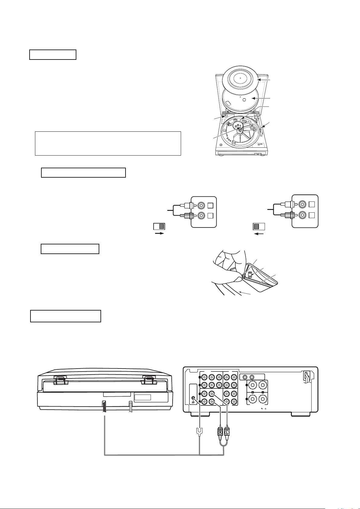
ASSEMBLY
1. Remove the main unit with the packing from
the box and take off the packing.
2. Set the 45-rpm adaptor on the main unit as
shown in the diagram.
3. Insert the turntable onto the center spindle.
4. Set the belt on the driving pulley. (The belt is
wound on the turntable.)
5. Set the turntable sheet on the turntable.
6. Remove the tie securing the tonearm.
45-rpm adaptor
Turntable sheet
Turntable
Equalizer Amplifier switch
Tonearm fixing tie
NOTE:
The turntable will not function if this tie is not
removed.
7.
8.
Equalizer Amplifier switch
9.
This unit has built-in RIAA
10.
equalizer amplifier,so it can
11.
be connected to an amplifier
12.
without PHONO(turntable)
13.
input jack. According to the
14.
amplifier, set the EQUALIZER
15.
AMPLIFIER SWITCH.
16.
When the unit is connected
to the PHONO(MM) jacks:
ON
OFF
Setting the belt
Grasp both sides of the tape and set the belt on the
motor pulley. Once the belt is set properly, remove
the tape.
Set the belt on the motor pulley properly as shown
in the diagram.
Center spindle
L
R
PHONO
When the unit is connected
to the AUX jacks, etc:
ON
OFF
AUX
Tape
Driving roller
Belt
Tur ntable
L
R
CONNECTIONS
1. Connect the left (white) and right (red) output cords respectively to your amplifier’s PHONO jacks
etc .
2. Connect the ground wire to the amplifier’s signal ground terminal.
3. Plug the power cord into a wall outlet. (Or if the amplifier has power outlets, plug it in there, but
before doing so, read the amplifier’s manual and check that the capacity is sufficient.)
PB
AUX-2 TAPE MD
REC
12
White
SYSTEM
CONNECTOR
L
R
SPEAKER SYSTEM
SPEAKER IMPEDANCE
4 16
Output cord
SIGNAL
Ground wire
2
INPUTS
CD
DVD/AUX
L
R
GND
TUNER PHONO TAPE MD
L
R
Red
Page 3
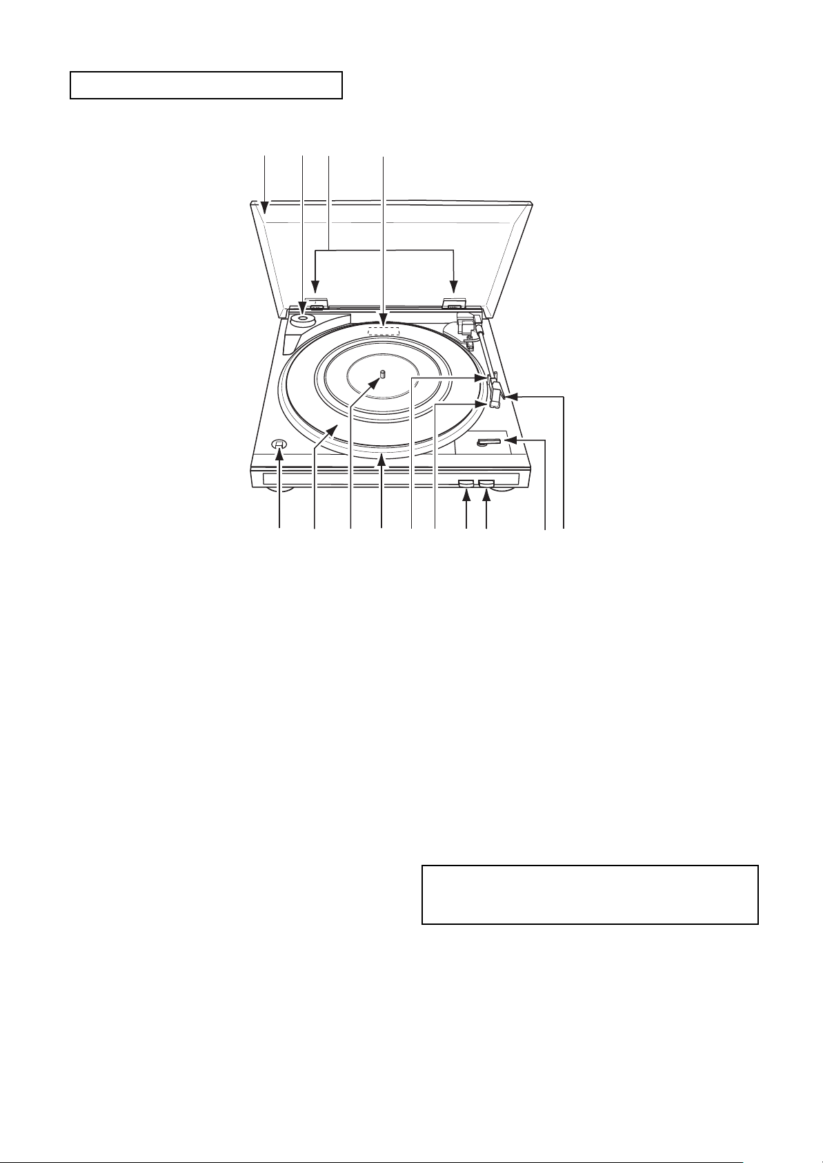
PART NAMES AND FUNCTIONS
23 4
1
14
1 Dust cover
2 45 rpm adaptor and holder
3 Dust cover hinge
4 Equalizer amplifier switch
5 Finger lever
6 Size Select Lever
Set according to the size of the record.
7 STOP Button
Press to stop playback.
8START Button
Press to start playback.
9 Cartridge
13
12
11
8
9
10
10 Tone arm rest
Holds the tone arm.
11 Platter
12 Spindle
13 Rubber mat
Place on the turntable.
14 SPEED Select Button
Set according to the record speed.
For 33 1/3 rpm: £
For 45 rpms: ¢
NOTE:
As this set is light, it may move when buttons or
knobs are operated, so do not press too
strongly.
7
5
6
3
Page 4
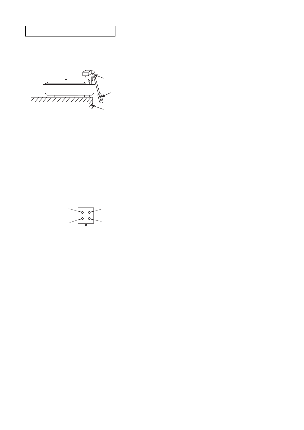
CARTRIDGE REPLACEMENT
(The cartridge forms a single body with the head shell. Use the following procedure to replace it.)
1. Remove the screw on the bottom of the head
shell sa shown in the diagram.
Screw (philips) small
Screwdriver
(philips) small
Desk, table, etc
2. Rotate the entire head shell gently in both directions.
The neck of the head shell is attached to the pipe
arm.
Turn it gently until the shell comes loose.
3. Carefully remove the head shell.
(Be careful not to break the lead wire.)
4. Remove the tip of the lead wire from the carridge terminal.
5. Install the new cartridge (with head shell).
The polarities are as shown on the diagram.
H
L
L
E
ground wire (white side)
(white)
Top
Tip side (as seen from the rear of the cartridge)
H
(Red)
R
E
ground wire (red side)
R
6. Assemble by following the removal procedure
in reverse order.
Use one drop of Cemedyne #3000 to atttach the
neck of the head shell and the pipe arm.
4
Page 5

METHOD OF ADJUSTMENT
1. Relationship between belt and pulley.
Check that the belt is not touching the collars
(A) of the motor pulley. If it is, remove the turntable and reattach the belt at the center of the
turntable skirt.
Motor pulley
Should not touch
here (A)
Belt
2. Speed adjustment
If the speed is off, adjust it with the variable
resistor on the motor control board.
Adjust for 33 r.p.m first, then set at 45 r.p.m
and check.
After adjusting, check the two speeds (33 and
45 r.p.m) once again.
This diagram shows the bottom panel.
Adj. Hole for 45 r.p.m
Adj. Hole for 33 r.p.m
Motor
Lead in
• Count increases when turned clockwise
• Count decreases when turned counterclockwise
Lead out
• Count increases when turned clockwise
• Count decreases when turned counterclockwise
This diagram shows the bottom panel.
Foot
Lead in adjust hole
Lead out adjust hole
L.IN
RET
SW
4. Stylus tip height adjustment
(1) Adjust the stylus tip height under standard
conditions.
(Standard conditions: with the turntable,
turntable sheet, and record set)
(2) The styus tip height should be adjusted to
about 6mm when returned (5-7mm at the
outermost position for 17cm records).
Foot
3. Lead in and lead out adjustment
(1) Lead in
(Test record: Hitachi HT-5 (30cm))
Check that the stylus lowers at 5 to 25
counts for both 17 cm and 30 cm records.
(2) Lead out
(Test record: Nippon Columbia EM-1001
(17cm))
Check that the pickup returns at 3 to 15
counts (3mm pitch).
If the counts are off , adjust as follows:
(a) Fasten the pickup to the arm rest.
(b) Insert a screwdriver into the lead in or lead
out adjustment holes and adjust.
Cartridge
Record
Turntable sheet
Stylus tip
Stylus tip height
Turntable
(3) If the stylus tip is too high, sound may be
distorted and the stylus may not advance.
If it is too low, it may scratch the record
when returning.
(4) Adjust using the lifter screw.
Turn clockwise to lower the stylus tip.
Turn counterclockwise to lift the stylus tip.
Adjust screw
Tip lifted when
turned this way
Tone arm
5
Page 6

NOTE FOR PARTS LIST
l Part indicated with the mark " " are not always in stock and possibly to take a long period of time for supplying, or in
some case supplying of part may be refused.
l When ordering of part, clearly indicate "1" and "I" (i) to avoid mis-supplying.
l Ordering part without stating its part number can not be supplied.
l Part indicated with the mark "H" is not illustrated in the exploded view.
l Not including Carbon Film ±5%, 1/4W Type in the P.W.Board parts list. (Refer to the Schematic Diagram for those parts.)
WARNING:WARNING:
WARNING:
WARNING:WARNING:
Parts marked with this symbol
Use ONLY replacement parts recommended by the manufacturer.
have critical characteristics.
ll
Resistors
l
ll
Ex.:RN 14K 2E 182 G FR
Type Shape Power Resist- Allowable Others
and per- ance error
formance
t
RD : Carbon 2B : 1/8W F :±1% P : Pulse-resistant type
RC : Composition 2E : 1/4W G : ±2% NL : Low noise type
RS : Metal oxide film 2H : 1/2W J :±5% NB : Non-burning type
RW : Winding 3A : 1W K : ±10% FR : Fuse-resistor
RN : Metal film 3D : 2W M :±20% F : Lead wire forming
RK : Metal mixture 3F : 3W
t
3H : 5W
t
t
] Resistance
1 8 2 ⇒ 1800 ohm = 1.8 kohm
s
s
• Units: ohm
1 R 2 ⇒ 1.2 ohm
s
s
• Units: ohm
Indicates number of zeros after effective number.
2-digit effective number.
1-digit effective number.
2-digit effective number, decimal point indicated by R.
ll
Capacitors
l
ll
Ex.:CE 04W 1H 2R2 M BP
Type Shape Dielectric Capacity Allowable Others
and per- strength error
formance
t
CE : Aluminum foil 0J : 6.3V F :±1% HS :High stability type
electrolytic
CA : Aluminum solid 1A : 10V G :±2% BP : Non-polar type
electrolytic
CS : Tantalum electrolytic 1C : 16V J :±5% HR : Ripple-resistant type
CQ : Film 1E : 25V K :±10% DL : For change and discharge
CK : Ceramic 1V : 35V M : ±20% HF : For assuring high
CC : Ceramic 1H : 50V Z : +80% U : UL part
CP : Oil 2A : 100V –20% C : CSA part
CM : Mica 2B : 125V P : +100% W : UL-CSA type
CF :Metallized 2C : 160V –0% F : Lead wire forming
CH :Metallized 2D : 200V C : ±0.25pF
t
2E : 250V D : ±0.5pF
2H : 500V = :Others
2J : 630V
t
t
frequency
] Capacity (electrolyte only)
2 2 2 ⇒ 2200µF
s
s
• Units: µF.
2 R 2 ⇒ 2.2µF
s
s
• Units: µF.
Indicates number of zeros after effective number.
2-digit effective number.
1-digit effective number.
2-digit effective number, decimal point indicated by R.
] Capacity (except electrolyte)
2 2 2 ⇒ 2200pF=0.0022µF
s
s
(More than 2) Indicates number of zeros after effective number.
• Units: µF.
2 2 1 ⇒ 220pF
s
s
(0 or 1) Indicates number of zeros after effective number.
• Units: pF.
• When the dielectric strength is indicated in AC, "AC" is included after the dieelectric
strength value.
2-digit effective number.
2-digit effective number.
6
Page 7

PARTS LIST OF EXPLODED
Ref. No.. Part No. Part Name Remarks Q'ty
1 941 0001 001 45 r.p.m. Adapter 1
2 941 0001 108 Strain Relief 1
3 941 0001 205 Dust Cover 1
5 941 0001 328 Bottom Cover for E3 1
5 941 0001 315 Bottom Cover for E2 1
6 941 0001 409 Knob for E3 2
6 941 0001 412 Knob for E2 2
7 941 0001 519 Rating Label for E3 1
7 941 0001 522 Rating Label for E2 1
8 941 0001 603 Pendulum (L) 1
9 941 0001 700 Pendulum (M) 1
10 941 0001 807 Select Record Knob for E3 1
10 941 0001 810 Select Record Knob for E2 1
11 941 0001 904 Serial No. Label 1
12 941 0002 000 Lifter 1
13 941 0002 107 Fixing Switch Set 1
14 941 0002 204 Pendulum (S) 1
15 941 0002 301 Shaft Holder 1
16 941 0002 408 Speed Bracket Ass'y 1
17 941 0002 505 Speed Support 1
19 941 0002 602 Selector 1
20 941 0002 709 Hinge Ass'y 1
21 941 0002 806 Select Plate 1
23 941 0002 903 Turntable 1
25 941 0003 009 Tonearm Shaft Set 1
27 941 0003 106 Locus Shaft 1
28 941 0003 203 Shaft 1
29 941 0003 300 Shaft 1
30 941 0003 407 Shaft 1
31 941 0003 504 Copper Washer 2
32 941 0003 601 Control Plate 1
36 941 0003 708 Cartridge 1
36-1 941 0003 805 Stylus Cover 1
36-2 DSN 82 Stylus 1
37 941 0003 902 Caution Label 1
38 941 0004 008 Washer 1
39 941 0004 105 Switch and Set Ass'y 1
40 941 0004 202 IC. P.W.B. Ass'y 1
41 941 0004 309 Micro Switch and Wire Ass'y 1
42 941 0004 406 Screw 1
43 941 0004 503 Screw 1
44 941 0004 707 AC Power Cord for E3 1
!
44 941 0004 804 AC Power Cord for E2 1
!
45 941 0004 901 Insulator 1
46 941 0005 104 Transformer for E3 1
!
46 941 0005 201 Transformer for E2 1
!
47 941 0005 308 Rectifyer P.W.B. Ass'y 1
49 941 0005 405 Screw 2
50 941 0005 502 Square Knob for E3 1
50 941 0005 515 Square Knob for E2 1
51 941 0005 609 Nut 1
52 941 0005 706 Nut 1
53 941 0005 803 Nut 1
54 941 0005 900 Screw 5
55 941 0006 006 Screw 5
57 941 0006 103 Screw 6
58 941 0006 200 Screw 1
59 941 0006 307 Screw 1
60 941 0006 404 Screw 4
62 941 0006 501 Screw 2
63 941 0006 608 Screw 1
64 941 0006 705 Screw 1
7
Page 8

Ref. No.. Part No. Part Name Remarks Q'ty
65 941 0006 802 Screw 4
66 941 0006 909 Screw 2
67 941 0007 005 Screw 1
68 941 0007 102 Screw 1
69 941 0007 209 Spring 1
70 941 0007 306 Spring 1
71 941 0007 403 Spring (SUS,304, WP8) 1
72 941 0007 500 Spring (SUS,304, WP8) 1
73 941 0007 607 Spring (SUS,304, WP8) 1
74 941 0007 704 Spring 1
75 941 0007 801 Play Spring 1
76 941 0007 908 Stop Spring 1
77 941 0008 004 Spring 1
78 941 0008 101 Spring(Play,Stop Knob) 2
79 941 0008 208 Spring 1
80 941 0008 305 Spring 1
81 941 0008 402 Spring 1
82 941 0008 509 Rubber (S.B.R) 2
83 941 0008 606 Slipmat Packing Ass'y 1
84 941 0008 703 Rubber 4
85 941 0008 800 Belt 1
86 941 0008 907 Rubber Foot for Motor 3
87 941 0009 003 Rubber Cap 1
88 941 0009 100 Washer 1
89 941 0009 207 E-Ring(3mm) 4
90 941 0009 304 E-Ring(5mm) 2
91 941 0009 401 CS Washer (3mm) 3
92 941 0009 508 Washer 1
93 941 0009 605 E-Ring(2mm) 1
94 941 0009 702 Washer 1
95 941 0009 809 Washer 1
96 941 0010 005 Washer 1
97 941 0010 102 Washer 1
98 941 0010 209 Washer 2
99 941 0010 306 Washer 1
103 941 0010 403 Foot (ABS) 2
108 941 0010 500 Return Link Ass'y 1
111 941 0010 607 Cueing Lever Ass'y 1
113 941 0010 704 Hinge Ass'y 1
118 941 0014 302 Signal Wire 1
151 941 0012 113 Chassis for E2 1
151 941 0012 126 Chassis for E3 1
152 941 0012 207 Tone Arm Ass'y for E3 1
152 941 0012 210 Tone Arm Ass'y for E2 1
153 941 0012 304 Center & Pinion Ass'y 1
154 941 0012 401 Cam Gear Ass'y 1
155 941 0012 508 Motor Ass'y 1
8
Page 9

PARTS LIST OF P.W.B. UNIT
I.C. P.W.B. ASS'Y
Ref. No. Part No. Part Name Remarks Q'ty
40 941 0004 202 I.C. P.W.B. ASS'Y 1
SW101 941 0014 001 Slide Sw(SBB-22-14) 1
- Elec. Capacitor(4.7uF/50V,M,Bulk 5*11) 1
IC101 958 0049 702 IC(UPC1228HA,8pin) 1
C108,208 - Ceramic Capacitor(1000pF/50V K Y5P Taping) 2
C102,107 - Elec. Capacitor(4.7uF/50V,M,Taping 5*11) 2
C202,207 - Elec. Capacitor(4.7uF/50V,M,Taping 5*11) 2
C104,204 - Elec. Capacitor(10uF/25V,M,Taping 5*11) 2
C105,205 - Mylar Capacitor(0.01uF J 50V Taping) 2
C101,103 958 0021 306 Ceramic Capacitor(100pF/50V K SL Taping) 2
C201,203 958 0021 306 Ceramic Capacitor(100pF/50V K SL Taping) 2
C106,206 - Mylar Capacitor(0.0027uF Taping) 2
C301,302 - Elec. Capacitor(100uF/16V,M,Taping 6.3*11) 2
R107,207 - Carbon Film Resistor(100K Ohm J 1/6W Taping 26mm) 2
R105,205 - Carbon Film Resistor(27K Ohm J 1/6W Taping 26mm) 2
R101,103 - Carbon Film Resistor(470 Ohm J 1/6W Taping 26mm) 2
R201,203 - Carbon Film Resistor(470 Ohm J 1/6W Taping 26mm) 2
R102,202 - Carbon Film Resistor(47K Ohm J 1/6W Taping 26mm) 2
R106,108 - Carbon Film Resistor(1K Ohm J 1/6W Taping 26mm) 2
R206,208 - Carbon Film Resistor(1K Ohm J 1/6W Taping 26mm) 2
R104,204 - Carbon Film Resistor(390K Ohm J 1/6W Taping 26mm) 2
R301 - Carbon Film Resistor(120 Ohm J 1/4W Taping 26mm) 1
RECTIFYER P.W.B. ASS'Y
Ref. No. Part No. Part Name Remarks Q'ty
47 941 0005 308 Rectifyer P.W.B. Ass'y 1
C1 254 4254 080 Elec. Capacitor(1000uF/16V,M,Bulk 13*21) 1
D1~D4 941 0013 002 Diode(1N4002,1A/100V,Bulk) 4
MICRO SWITCH AND WIRE ASS'Y
Ref. No. Part No. Part Name Remarks Q'ty
41 941 0004 309 Micro Switch and Wire Ass'y 1
SW101 941 0014 205 Push Sw(SPEA12MC06-HF) 1
9
Page 10

WARNING:
Parts marked with this symbol have critical
characteristics.
Use ONLY replacement parts recommended by the
manufacturer.
10
The symbols above indicate the
following destinations.
E3 : U.S.A.&Canada model
E2 : Europe model
Page 11

PA CKING & ACCESSORIES
201
202
208
209
205
203
206
207
PARTS LIST OF PACKING & ACCESSORIES (not included EXPLODED VIEW)
Ref. No. Part No. Part Name Remarks Q'ty
201 941 0008 606 Slipmat Packing Ass'y 1
202 941 0011 114 Envelope sub Ass'y for E3 1
202 941 0011 127 Envelope sub Ass'y for E2 1
511 3872 007 Inst. Manual for E3 1
511 3872 007 Inst. Manual for E2 1
511 3865 001 Inst. Manual for E2 1
203 941 0011 224 Carton Case 1
205 941 0011 305 Cushion(L) 1
206 941 0011 402 Cushion(R) 1
207 941 0002 903 Turntable 1
208 941 0001 205 Dust Cover Ass'y 3+82 1
209 941 0011 509 Poly Cover for Main 1
11
Page 12

SCHEMATIC DIAGRAM
I.C. P.W.B. ASS'Y
WIRING DIAGRAM
GND
Tone Arm
BLK
WHT
WHT
RED
(L)
GND
PHONO
RED
(R)
GND
BRN
BRN
YEL
YEL
RECTIFYER P.W.B. ASS'Y
AC 120V
AC 230V
AC Cord
60Hz (U.S.A. & Canada)
50Hz (Europe)
POWER TRANS
BLK
Leaf Switch
RED
WHT
Leaf Switch
RED
RED
Fix to turn table
Shaft Earth
BLK
Phono Motor
12
BLK
WHT
RED
YEL
Speed Changable Switch
£33 ¢45
 Loading...