

Page 1
e
SERVICE MANUAL
MODEL JP E3 E2 EK K2A E1C E1K EUT
Ver. 1
DP-200USB
FULL AUTOMATIC TURNTABLE SYSTEM
P P
For purposes of improvement, specications and design are subject to change without notice.
●
Please use this service manual with referring to the operating instructions without fail.
●
Some illustrations using in this service manual are slightly different from the actual set.
●
e
Denon Brand Company, D&M Holdings Inc.
X0392 V.01 DE/CDM 0811
Page 2

SAFETY PRECAUTIONS
The following check should be performed for the continued protection of the customer and service technician.
LEAKAGE CURRENT CHECK
Before returning the unit to the customer, make sure you make either (1) a leakage current check or (2) a line to chassis
resistance check. if the leakage current exceeds 0.5 milliamps, or if the resistance from chassis to either side of the power
cord is less than 460 kohms, the unit is defective.
CAUTION
Heed the cautions!
◎
Spots requiring particular attention when servicing, such
as the cabinet, parts, chassis,etc., have cautions indicated
on labels. be sure to heed these causions and the cautions
indicated in the handling instructions.
Caution concerning electric shock!
◎
(1) An AC voltage is impressed on this set, so touching
internal metal parts when the set is energized could
ca use e lectric shock. Take car e to avoid elect ric
shock, by for example using an isolating transformer
and gloves when servicing while the set is energized,
unplugging the power cord when replacing parts, etc.
(2) Tere are high voltage parts inside. Handle with extra
care when the set is energized.
Caution concerning disassembly and
◎
Please heed he points listed below during servicing and inspection.
assembly!
Through great care is taken when manufacturing parts
from sheet metal, there may in some rare cases be burrs
on the edges of parts which could cause injury if ngers
are moved across them. Use gloves to protect your hands.
Only use designated parts!
◎
Th e s et's parts hav e s pec ifi c safety properties (fi re
resistance, voltage resistance, etc.). For replacement parts,
be sure to use parts which have the same poroperties. In
particular, for the important safety parts that are marked
on wiring diagrams and parts lists, be sure to use the
z
designated parts.
Be sure to mount parts and arrange the wires
◎
as they were originally!
For safety seasons, some parts use tape, tubes or other
insulating materials, and some parts are mounted away
from the surface of printed circuit boards. Care is also
taken with the positions of the wores omsode amd clamps
are used to keep wires away from heating and high voltage
parts, so be sure to set everything back as it was originally.
Inspect for safety after servicing!
◎
Ch eck that all scr ews , pa rts and wir es r emo ved or
disconnected for servicing have been put back in their
original positions, inspect that no parts around the area that
has been serviced have been negatively affected, conduct
an inslation check on the external metal connectors and
between the blades of the power plug, and otherwise
check that safety is ensured.
(Insulation check procedure)
Unplug the power cord from the power outlet, disconnect
the antenna, plugs, etc., and turn the power switch on.
Using a 500V insulation resistance tester, check that the
inplug and the externally exposed metal parts (antenna
terminal, headphones terminal, input terminal, etc.) is
1MΩ or greater. If it is less, the set must be inspected and
repaired.
CAUTION
Concerning important safety
parts
Many of the electric and structural parts used in the set
have sp ecial safe ty properties. In most cases thes e
properties are difficult to distinguish by sight, and using
replacement parts with higher ratings (rated power and
withstand voltage) does not necessarily guarantee that
safety performance will be poreserved. Parts with safety
properties are indicated as shown below on the wiring
diagrams and parts lists is this service manual. Be sure to
replace them with parts with the designated part number.
(1) Schematic diagrams ...... Indicated by the z mark.
(2) Parts lists ...... Indicated by the z mark.
Using parts other than the designated
parts could result in electric shock, res
or other dangerous situations.
2
DP-200USB
Page 3
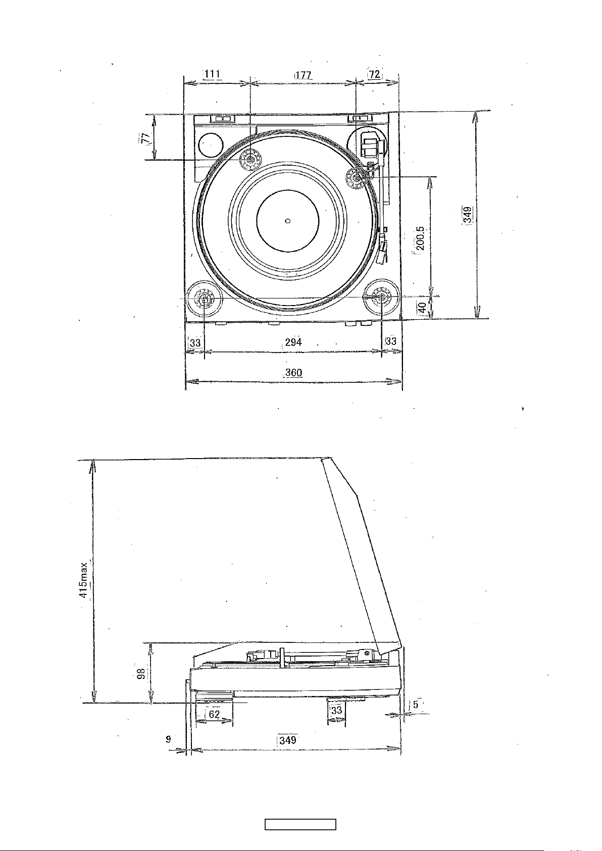
DIMENSION
3
DP-200USB
Page 4
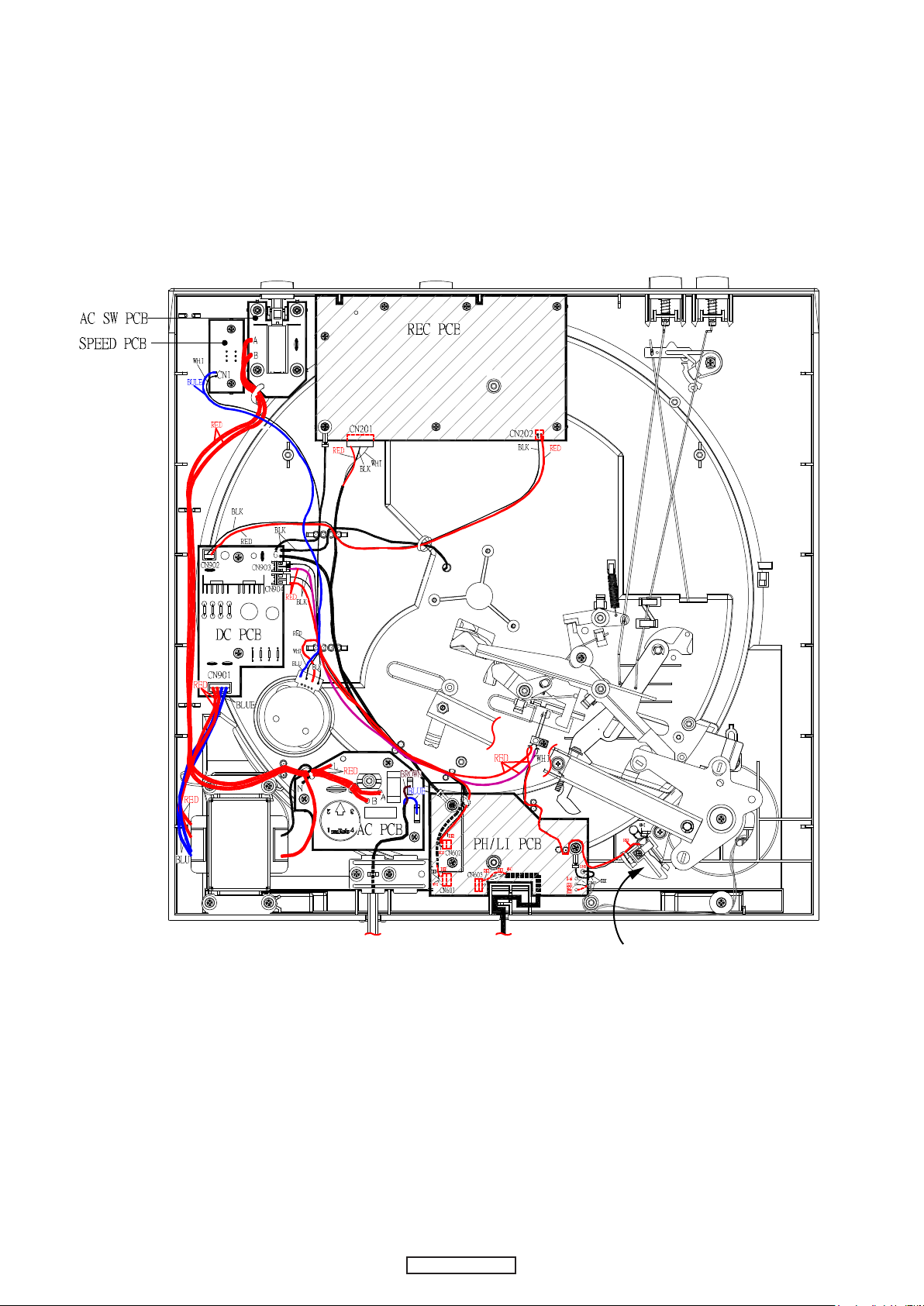
WIRE ARRANGEMENT
SW1
Leaf
SW
Leaf SWSgnal wireAC cord
4
DP-200USB
Page 5
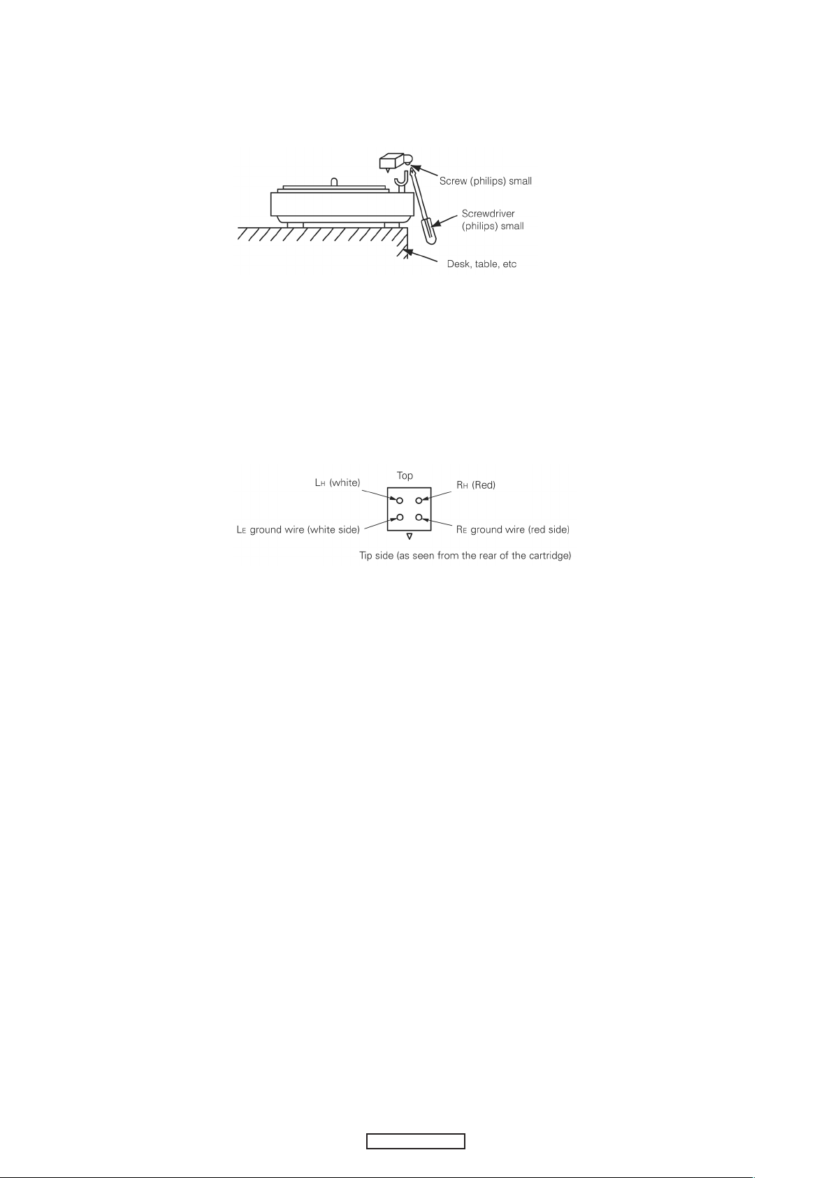
CARTRIDGE REPLACEMENT
(The cartrige forms a single body with the head shell. Use the following procedure to replace it.)
1.Remove the screw on the bottom of the head shell as shown in the diagram.
2. Rotate the entire head shell gently in both directions.
The neck of the head shell is attached to the pipe arm.
Turn it gently until the shell comes loose.
3. Carefully remove the head shell.
(Be careful not to break the lead wire.)
4. Remove the tip of the lead wire from the carridge terminal.
5. Install the new cartridge (with head shell).
The polarities are as shown on the diagram.
6. Assemble by following the removal procedure in reverse order.
Use one drop of Cemedyne #3000 to attach the neck of the head shell and the pipe arm.
5
DP-200USB
Page 6
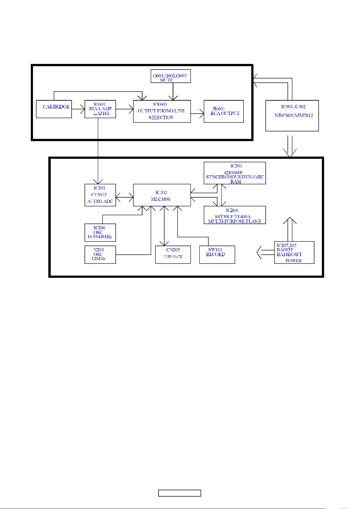
BLOCK DIAGRAMS
6
DP-200USB
Page 7
METHOD OF ADJUSTMENT
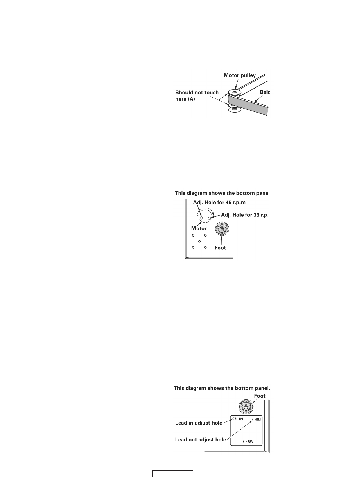
1.Relationship between belt and pulley.
Check that the belt is not touching the collars (A) of the motor
pulley. If it is, remove the turntable and reattach the belt at the
center of the turntable skirt.
2.Speed adjustment
If the speed is off, adjust it with the variable resistor on the
motor control board.
Adjust for 33 r.p.m rst, then set at 45 r.p.m and check.
After adjusting, check the two speeds (33 and 45 r.p.m) once
again.
3.Lead in and lead out adjustment
(1) Lead in
(test record: Hitachi HT-5 (30cm))
Check that the stylus lowers at 5 to 25 counts for both 17cm and 30 cm
records.
(2) Lead out
(Test record: Nippon Columbia EM-1001 (17cm))
Check that the pickup returns at 3 to 15 counts (3mm pitch).
If the counts are off, adjust as follows:
(a) Fasten the pickup to the arm rest.
(b) Insert a scrwedriver into the lead in or lead out adjustment holes and
adjust.
Lead in
Count increases when turned clockwise
・
Count decreases when turned counterclockwise
・
Lead out
Count increases when turned clockwise
・
Count decreases when turned counterclockwise
・
7
DP-200USB
Page 8
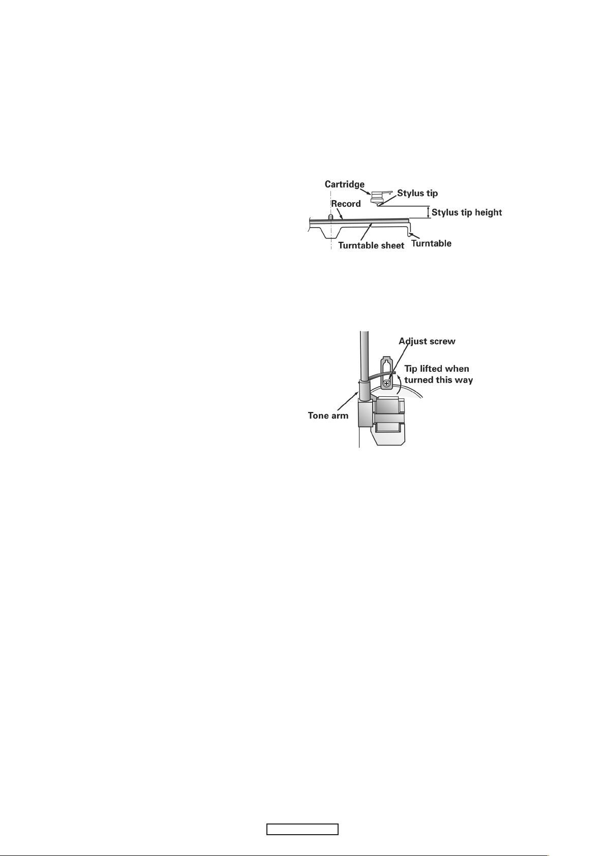
4.Stylus tip height adjustment
(1) Adjust the stylus tip height under standard conditions.
(Standard conditions: with the turntable, turntable sheet,
and record set)
(2) The stylus tip theight should be adjusted to about 6mm
when returned (5-7mm at the outermost position for 17cm
records).
(3) If the stylus tip is too high, sound may be distorted and the
stylus may not advance.
If it is too low, it may scratch the record when returning.
(4) Adjust using the lifter screw.
Turn clockwise to lower the stylus tip.
・
Turn counterclockwise to lift the stylus tip.
・
8
DP-200USB
Page 9
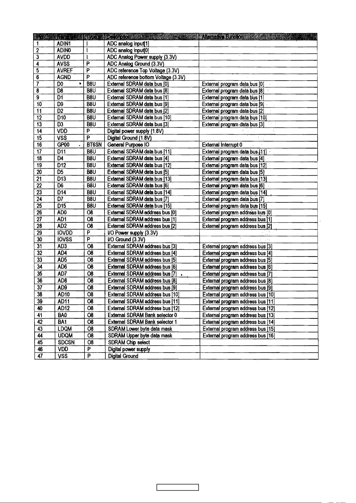
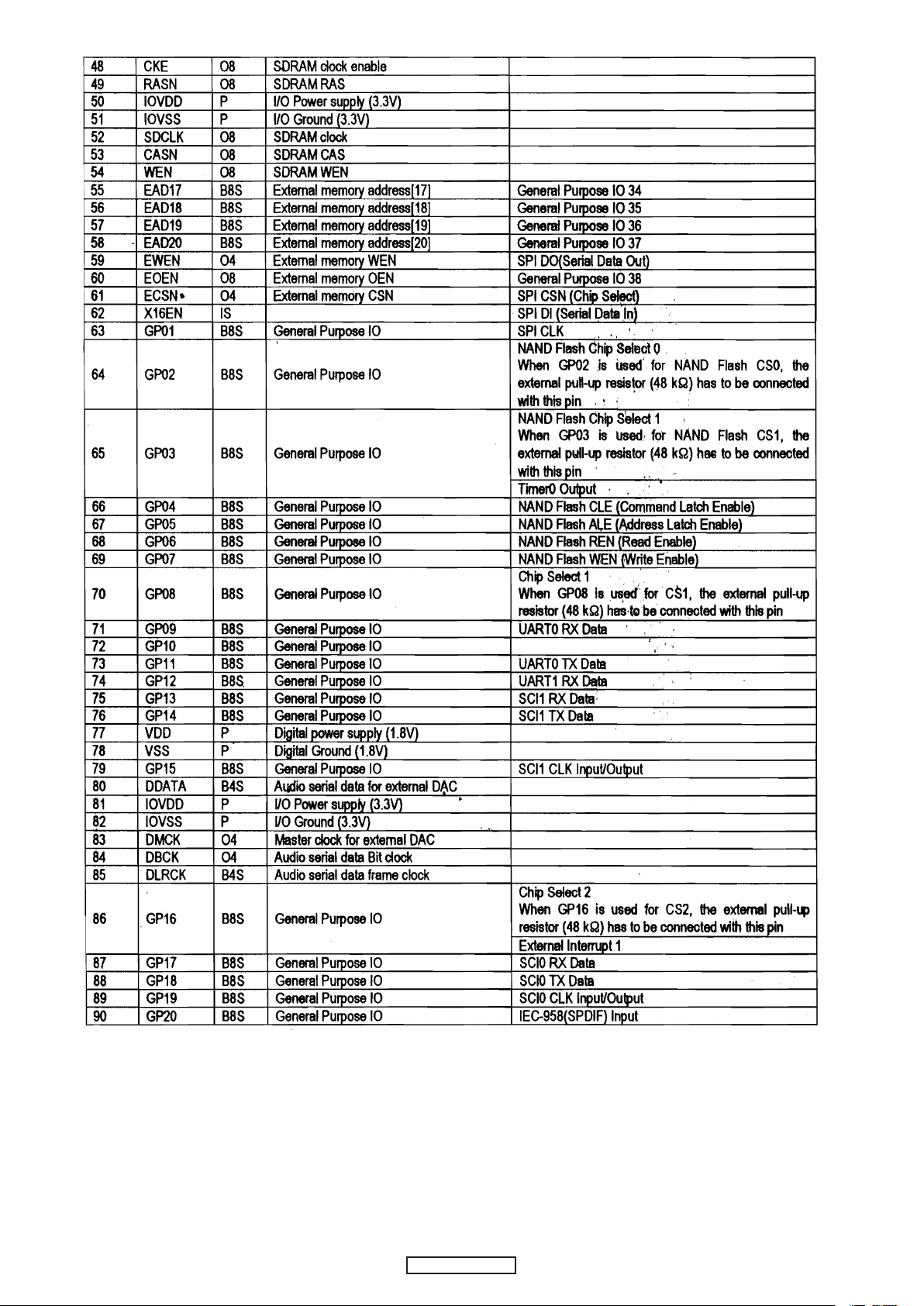
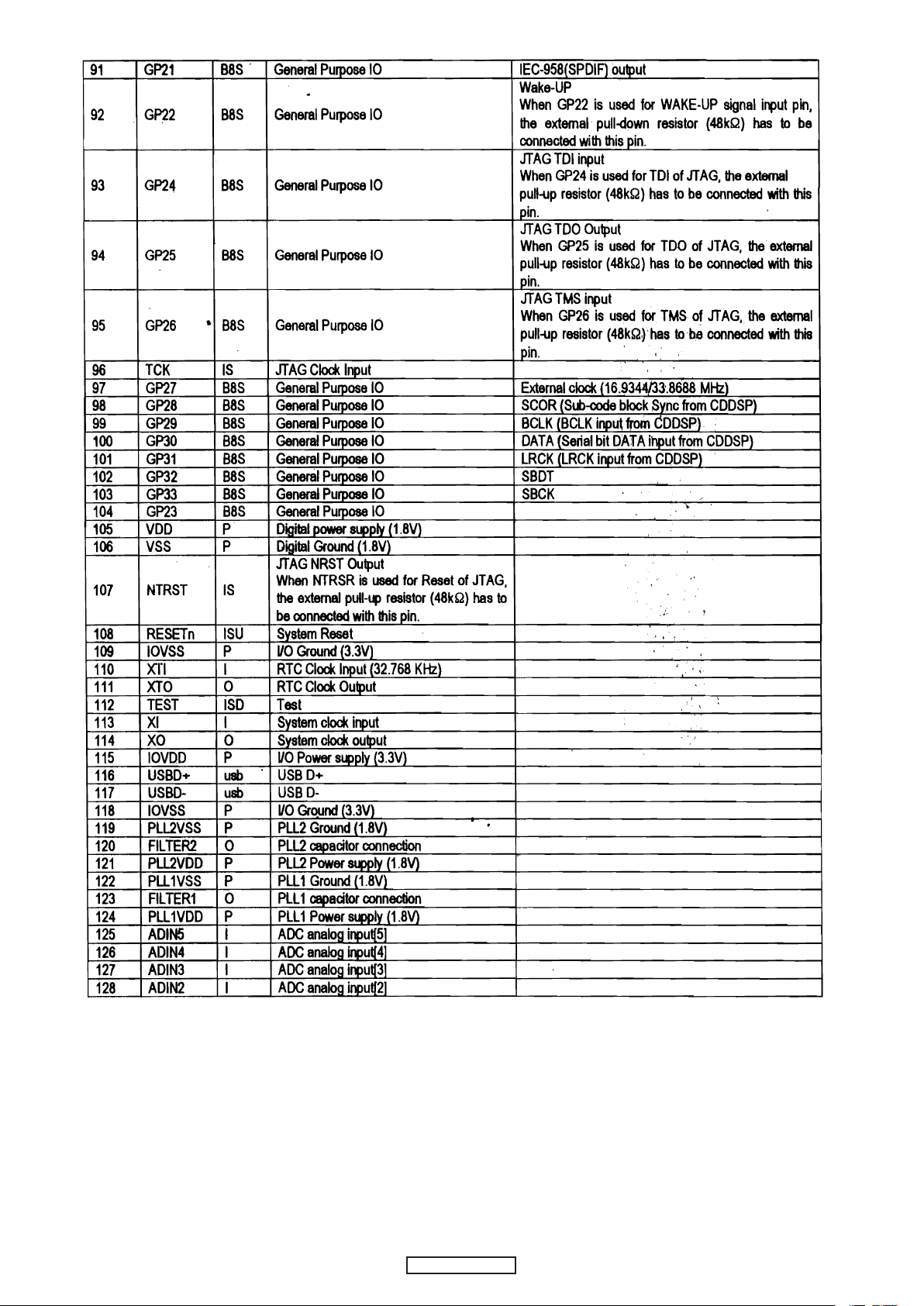
SEMICONDUCTORS
AD5/EAD533AD6/EAD634AD7/EAD735AD8/EAD836AD9/EAD9
37
AD10/EAD1038AD11/EAD1139AD12/EAD12
40
BA0/EAD1341BA1/EAD14
42
LDQM/EAD15
43
UDQM/EAD1 6
44
SDSCN
45
VDD
46
VSS
47
CKE
48
RASN
49
IOVDD
50
IOVSS
51
SDCLK
52
CASN
53
WEN
54
EAD17/GP34
55
EAD18/GP35
56
EAD19/GP36
57
EAD20/GP37
58
EWEN
59
EOEN/GP38
60
ECSN
61
XI16EN/SPIDI
62
GP0163GP02
64
GP2797SCOR/GP2898BCLK/GP2999DATA/GP30
100
LRCK/GP31
101
SBDT/GP32
102
SBCK/GP33
103
GP23
104
VDD
105
VSS
106
NTRST
107
RESETN
108
IOVSS
109
XTI
110
XTO
111
TEST
112XI113XO114
IOVDD
115
USBD+
116
USBD-
117
IOVSS
118
PLL2VSS
119
FILTER2
120
PLL2VDD
121
PLL1VSS
122
FILTER1
123
PLL1VDD
124
ADIN5
125
ADIN4
126
ADIN3
127
ADIN2
128
Only major semiconductors are shown, general semiconductors etc. are omitted to list.
The semiconductor which described a detailed drawing in a schematic diagram are omitted to list.
1. IC's
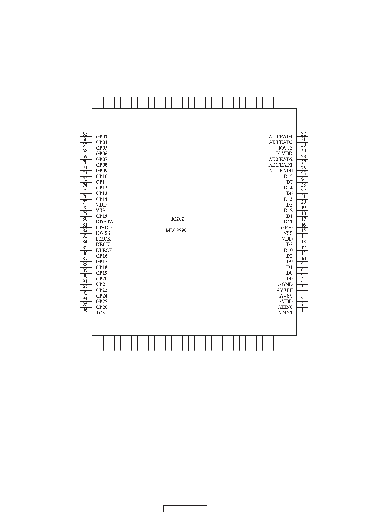
MLC3890 (IC202)
9
9
DP-200USB
DP-200USB
Page 10
Terminal Function
10
10
DP-200USB
DP-200USB
Page 11
11
11
DP-200USB
DP-200USB
Page 12
12
12
DP-200USB
DP-200USB
Page 13

IS42S16100E-7TL (IC203
)
13
13
DP-200USB
DP-200USB
Page 14

14
14
DP-200USB
DP-200USB
Page 15

SST39LF/VF400A (IC204
)
BLOCK DIAGRAM
PIN FUNCTION
15
15
DP-200USB
DP-200USB
Page 16

PRINTED WIRING BOARDS
REC P.W.B. UNIT (1/2)
16
DP-200USB
COMPONENT SIDE
Page 17

REC P.W.B. UNIT (2/2)
17
DP-200USB
FOIL SIDE
Page 18

PH/LI/SPEED/AC SW/AC/DC P.W.B. UNIT (1/2)
18
DP-200USB
COMPONENT SIDE
Page 19

PH/LI/SPEED/AC SW/AC/DC P.W.B. UNIT (2/2)
19
DP-200USB
FOIL SIDE
Page 20

NOTE FOR PARTS LIST
Parts for which "nsp" is indicated on this table cannot be supplied.
When ordering of part, clearly indicate "1" and "I" (i) to avoid mis-supplying.
Ordering part without stating its part number can not be supplied.
Not including General-purpose Carbon Chip Resistor in the P.W.Board parts list. (Refer to the Schematic Diagram for those parts.)
Parts marked with this symbol z have critical characteristics.
Use ONLY replacement parts recommended by the manufacturer.
Not including General-purpose Carbon Film Resistor in the P.W.Board parts list. (Refer to the Schematic Diagram for those parts.)
Part indicated with the mark "★" is not illustrated in the exploded view.
WARNING:
1.
2.
3.
4.
5.
6.
● Resistors
RD : Carbon
RC : Composition
RS : Metal oxide film
RW: winding
RN : Metal film
RK : Metal mixture
P : Pulse-resistant type
NL : Low noise type
NB : Non-burning type
FR : Fuse-resistor
F : Lead wire forming
2B : 1/8 W
2E : 1/4 W
2H : 1/2 W
3A : 1 W
3D : 2 W
3F : 3 W
3H : 5 W
F : ±1%
G : ±2%
J : ±5%
K : ±10%
M : ±20%
Ex.: RN
Type
14K
Shape
and performance
2E
Power
182
Resistance
G
Allowable
error
FR
Others
* Resistance
1800ohm=1.8kohm1 8 2
Indicates number of zeros after effective number.
2-digit effective number.
1.2ohm1 R 2
2-digit effective number, decimal point indicated by R.
1-digit effective number.
: Units: ohm
● Capacitors
CE : Aluminum foil
electrolytic
CA : Aluminium solid
electrolytic
CS : Tantalum electrolytic
CQ : Film
CK : Ceramic
CC : Ceramic
CP : Oil
CM: Mica
CF : Metallized
CH : Metallized
HS : High stability type
BP : Non-polar type
HR : Ripple-resistant type
DL : For change and discharge
HF : For assuring high requency
U : UL part
C : CSA part
W : UL-CSA part
F : Lead wire forming
0J : 6.3 V
1A : 10 V
1C : 16 V
1E : 25 V
1V : 35 V
1H : 50 V
2A : 100 V
2B : 125 V
2C : 160 V
2D : 200 V
2E : 250 V
2H : 500 V
2J : 630 V
F : ±1%
G : ±2%
J : ±5%
K : ±10%
M : ±20%
Z : ±80%
: - 20%
P : +100%
C : ±0.25pF
D : ±0.5pF
= : Others
Ex.: CE
Type
04W
Shape
and performance
1H
Dielectric
strength
3R2
CapacityMAllowable
error
BP
Others
・ Units:μF.
2200μF2 2 2
Indicates number of zeros after effective number.
2-digit effective number.
・ Units:μF.
2.2μF2 R 2
2-digit effective number, decimal point indicated by R
1-digit effective number.
* Capacity (electrolyte only)
・ When the dielectric strength is indicated in AC,"AC" is included after the dieelectric strength value.
* Capacity (except electrolyte)
・ Units:pF
2200pF=0.0022μF2 2 2
Indicates number of zeros after efective number.
(More than 2)
2-digit effective number.
・ Units:pF
220pF2 2 1
2-digit effective number.
Indicates number of zeros after effective numver.
(0 or 1)
20
DP-200USB
Page 21

PARTS LIST OF P.W.B. UNIT
* Parts for which "nsp" is indicated on this table cannot be supplied.
* P.W.B. ASS'Y for which "nsp" is indicated on this table cannot be supplied. When repairing the P.W.B. ASS'Y, check the board parts table and order
replacement parts.
* The parts listed below are for maintenance only, might differ from the parts used in the unit in appearances or dimensions.
Note:The symbols in the column "Remarks" indicate the following destinations.
E3 : U.S.A. & Canada model E2 : Europe model
REC PCB ASS'Y
Ref No. Part No. Part Name Remarks Q'ty New
SEMICONDUCTORS GROUP
IC201 941239000410S
IC202 941239000450S
IC203 941239000460S
IC204 941243000350D
IC205 00D9410049209
IC206 00D9580048800
IC207 00D9587058204
IC208 00D2623082924
IC(CE2632,SOP-14)
IC(MLC3890,TQFP-128)
IC(1S42S16100E-7TL,TSOP-50,ISSI)
IC ASS'Y (SST39LF/VF400A,TSOP-48)
IC(BA18BC0FP-E2,3PIN,TO-252-3,SMD)
IC(TC74HCU04AFN/TC74HCU04FAN(ELP.M)SOP-14)
IC(BA033FP-E2,TO-252-3)
IC(BD4730G-TR,SSOP-5)
417-BJR100-830
417-BJR100-831
417-BJR100-832
704-BJR100-7493
417-MCDS4-737
417-DJ150-419
417-CTB200-500
417-200USB-931
1 *
1 *
1 *
1 *
1 *
1 *
1 *
1 *
*
Q202,Q203 00D9587057409
D201 941209000470S
D202 00D9410046901
D203 00D9587056701
D204 00D9587051706
D204 nsp
D205 00D9580041807
D205 nsp
D206-D208 941209000470S
RESISTOR GROUP
R201 nsp
R202 nsp
R203 nsp
R204 nsp
R205-R208 nsp
R209 nsp
R210 nsp
R211,R212 nsp
R214 nsp
R216 nsp
R217 nsp
R218 nsp
R219-R221 nsp
R222 nsp
R223 nsp
R224 nsp
R225 nsp
R226 nsp
R227-R230 nsp
R231 nsp
R232 nsp
R233 nsp
R234 nsp
R235-R237 nsp
R238 nsp
R239,R240 nsp
R241,R242 nsp
R243 nsp
R244-R246 nsp
R247 nsp
R248,R249 nsp
R250,R251 nsp
R252,R253 nsp
R255,R254 nsp
R256 nsp
CHIP TRANSISTOR(2SC2412KT146R)
ESD DIODE(RSB6.8S 150mW.6.8V EMD2 ROHM)
SWITCHING DIODE(1SS355,UMD2,SMD,TAPING)
DIODE(RB160M-30,SOD-123)
LED (6224-10ID-A,RED )
LED HOLDER(LED-3Y,BLACK,H=4.0mm)
LED ( GREEN )
LED HOLDER(LED-3Y,BLACK,H=4.0mm)
ESD DIODE(RSB6.8S 150mW.6.8V EMD2 ROHM)
NOTE :
When update Firmware, please conrm a last version in SDI.
Use the service board after updating it.
CHIP RESISTOR(10K OHM,1/10W,0603,J,TP ,50V)
CHIP RESISTOR(15K OHM,1/10W,0603,J,TP ,50V)
CHIP RESISTOR(10K OHM,1/10W,0603,J,TP ,50V)
CHIP RESISTOR(15K OHM,1/10W,0603,J,TP ,50V)
CHIP RESISTOR(470 OHM,1/10W, 0603,J,TP,50V)
CHIP RESISTOR(4.7K OHM,1/10W, 0603,J,TP,50V)
CHIP RESISTOR(0 OHM,1/10W, 0603,J,TP,50V)
CHIP RESISTOR(470 OHM,1/10W, 0603,J,TP,50V)
CHIP RESISTOR(1M OHM,1/8W, 0805,J,TP 150V)
CHIP RESISTOR(10K OHM,1/10W,0603,J,TP ,50V)
CHIP RESISTOR(100 OHM,1/10W, 0603,J,TP,50V)
CHIP RESISTOR(1K OHM,1/10W, 0603,J,TP,50V)
CHIP RESISTOR(100 OHM,1/10W, 0603,J,TP,50V)
CHIP RESISTOR(4.7K OHM,1/10W, 0603,J,TP,50V)
CHIP RESISTOR(1K OHM,1/10W, 0603,J,TP,50V)
CHIP RESISTOR(0 OHM,1/10W, 0603,J,TP,50V)
CHIP RESISTOR(0 OHM,1/8W,1206,J,TP ,150V)
CHIP RESISTOR(100 OHM,1/8W,J,0805,150V)
CHIP RESISTOR(100 OHM,1/10W, 0603,J,TP,50V)
CHIP RESISTOR(47K OHM,1/10W,0603,J,TP ,50V)
CHIP RESISTOR(100K OHM,1/10W,0603 ,J,TP ,50V)
CHIP RESISTOR( 220 OHM,1/8W,0805,J,TP 150V )
CHIP RESISTOR(1M OHM,1/8W, 0805,J,TP 150V)
CHIP RESISTOR(0 OHM,1/10W, 0603,J,TP,50V)
CHIP RESISTOR(47K OHM,1/10W,0603,J,TP ,50V)
CHIP RESISTOR(39 OHM,1/10W,0603,J,TP ,50V)
CHIP RESISTOR(15K OHM,1/10W,0603,J,TP ,50V)
CHIP RESISTOR(10K OHM,1/8W,0805,J,TP 150V)
CHIP RESISTOR(220 OHM,1/10W,0603 ,J,TP 50V)
CHIP RESISTOR( 220 OHM,1/8W,0805,J,TP 150V )
CHIP RESISTOR(220 OHM,1/10W,0603 ,J,TP 50V)
CHIP RESISTOR(1K OHM,1/10W, 0603,J,TP,50V)
CHIP RESISTOR(10K OHM,1/8W,0805,J,TP 150V)
CHIP RESISTOR(1K OHM,1/8W, 0805,J,TP 150V)
CHIP RESISTOR(220 OHM,1/10W,0603 ,J,TP 50V)
416-CDN88-051
414-DJ1100G-207
414-CD1000-075
414-900-208
410-CD6000-122
504-BJR100-224
410-CD6000-124
504-BJR100-224
414-DJ1100G-207
412-CDVD2001-534
412-007USB-687
412-CDVD2001-534
412-007USB-687
412-CDVD2001-545
412-CDVD2001-523
412-CDVD2001-552
412-CDVD2001-545
412-DV330-308
412-CDVD2001-534
412-CDVD2001-530
412-CDVD2001-540
412-CDVD2001-530
412-CDVD2001-523
412-CDVD2001-540
412-CDVD2001-552
412-DJ3000-414
412-DV330-304
412-CDVD2001-530
412-CDVD2001-532
412-CDVD2001-537
412-DV330-333
412-DV330-308
412-CDVD2001-552
412-CDVD2001-532
412-DCM280-755
412-007USB-687
412-DV330-306
412-CDVD2001-521
412-DV330-333
412-CDVD2001-521
412-CDVD2001-540
412-DV330-306
412-DV330-305
412-CDVD2001-521
2
4
1
1
1 *
2 *
1 *
2 *
4
3
4
3
4
6
2
5
6
2
3
8
4
8
2
4
5
2
1
8
2
1
2
2
5
2
2
4
3
6
2
6
4
3
2
6
21
DP-200USB
Page 22

Ref No. Part No. Part Name Remarks Q'ty New
CAPACITORS GROUP
C201 nsp
C202 00D9587056206
C203 nsp
C204 00D9587056206
C205 nsp
C206 00D9587056400
C207 nsp
C208 00D9587056400
C209 00D9587054907
C210 nsp
C211 00D9587054907
C212 nsp
C213 00D9587056206
C214 nsp
C215,C216 nsp
C217,C218 nsp
C219 nsp
C220,C221 nsp
C222-C230 nsp
C231 nsp
C232,C233 nsp
C234 00D9587054907
C235,C236 nsp
C237 00D9587054907
C238 nsp
C239 nsp
C240 00D9587054907
C241 941134000530S
C242 nsp
C243,C244 nsp
C246-C248 nsp
C250-C252 nsp
C253 nsp
C254,C255 nsp
C256-C258 nsp
C259 nsp
C260,C261 nsp
C262 00D9587032709
C263 nsp
C264-C268 00D9587054907
C269 nsp
CHIP CAPACITOR(100pF/50V,J,0603 TYPE,NPO)
ELEC. CAPACITOR(1uF/50V,M,105 ,TAPING 4*7,MINI)
CHIP CAPACITOR(100pF/50V,J,0603 TYPE,NPO)
ELEC. CAPACITOR(1uF/50V,M,105 ,TAPING 4*7,MINI)
CHIP CAPACITOR(0.1uF/50V,Z,0603 TYPE,Y5V)
ELEC. CAPACITOR(22uF/16V,M,105 ,TAPING 4*7,MINI)
CHIP CAPACITOR(0.1uF/50V,Z,0603 TYPE,Y5V)
ELEC. CAPACITOR(22uF/16V,M,105 ,TAPING 4*7,MINI)
ELEC. CAPACITOR(100uF/10V,M,105 ,TAPING 5*7,MINI)
CHIP CAPACITOR(0.1uF/50V,Z,0603 TYPE,Y5V)
ELEC. CAPACITOR(100uF/10V,M,105 ,TAPING 5*7,MINI)
CHIP CAPACITOR(0.1uF/50V,Z,0603 TYPE,Y5V)
ELEC. CAPACITOR(1uF/50V,M,105 ,TAPING 4*7,MINI)
CHIP CAPACITOR(0.1uF/50V,Z,0603 TYPE,Y5V)
CHIP CAPACITOR(22pF/50V,J,0805 TYPE,NPO)
CHIP CAPACITOR(0.1uF/50V,Z,0603 TYPE,Y5V)
CHIP CAPACITOR(0.01uF/50V,K,0603 TYPE,X7R)
CHIP CAPACITOR(1200pF/50V,K,0603 TAPING,X7R)
CHIP CAPACITOR(0.1uF/50V,Z,0603 TYPE,Y5V)
CHIP CAPACITOR(0.1uF/ 50V,Z,0805 TYPE,Y5V)
CHIP CAPACITOR(22pF/50V,J,0805 TYPE,NPO)
ELEC. CAPACITOR(100uF/10V,M,105 ,TAPING 5*7,MINI)
CHIP CAPACITOR(100pF/50V,J,0603 TYPE,NPO)
ELEC. CAPACITOR(100uF/10V,M,105 ,TAPING 5*7,MINI)
CHIP CAPACITOR(0.1uF/50V,Z,0603 TYPE,Y5V)
CHIP CAPACITOR(0.1uF/ 50V,Z,0805 TYPE,Y5V)
ELEC. CAPACITOR(100uF/10V,M,105 ,TAPING 5*7,MINI)
ELEC. CAPACITOR(470uF/10V,M, 105 ,TAPING 8*12)
CHIP CAPACITOR(0.1uF/ 50V,Z,0805 TYPE,Y5V)
CHIP CAPACITOR(0.1uF/50V,Z,0603 TYPE,Y5V)
CHIP CAPACITOR(0.1uF/50V,Z,0603 TYPE,Y5V)
CHIP CAPACITOR(0.1uF/50V,Z,0603 TYPE,Y5V)
CHIP CAPACITOR(0.01uF/50V,K,0603 TYPE,X7R)
CHIP CAPACITOR(0.01uF/50V,K,0805 TYPE,X7R)
CHIP CAPACITOR(0.01uF/50V,K,0603 TYPE,X7R)
CHIP CAPACITOR(0.01uF/50V,K,0805 TYPE,X7R)
CHIP CAPACITOR(0.1uF/ 50V,Z,0805 TYPE,Y5V)
ELEC. CAPACITOR(220uF/10V,M,105 ,TAPING 6*7,MINI)
CHIP CAPACITOR(0.1uF/ 50V,Z,0805 TYPE,Y5V)
ELEC. CAPACITOR(100uF/10V,M,105 ,TAPING 5*7,MINI)
CHIP CAPACITOR(0.1uF/50V,Z,0603 TYPE,Y5V)
413-DCM280-767
413-SPPW3-234
413-DCM280-767
413-SPPW3-234
413-DCM280-773
413-SPPW3-236
413-DCM280-773
413-SPPW3-236
413-HMA2200-5017
413-DCM280-773
413-HMA2200-5017
413-DCM280-773
413-SPPW3-234
413-DCM280-773
413-CDN88-080
413-DCM280-773
413-DCM280-771
413-ME2-1049
413-DCM280-773
413-DV330-313
413-CDN88-080
413-HMA2200-5017
413-DCM280-767
413-HMA2200-5017
413-DCM280-773
413-DV330-313
413-HMA2200-5017
413-HT8015-169
413-DV330-313
413-DCM280-773
413-DCM280-773
413-DCM280-773
413-DCM280-771
413-DV330-312
413-DCM280-771
413-DV330-312
413-DV330-313
413-HT801K-192
413-DV330-313
413-HMA2200-5017
413-DCM280-773
4
3
4
3
26
2
26
2
10
26
10
26
3
26
4
26
5
2
26
6
4
10
4
10
26
6
10
1
6
26
26
26
5
3
5
3
6
1
6
10
26
OTHER PARTS GROUP
CN201 nsp
CN202 nsp
CN203 941643000340S
JR1 nsp
L201-L205 00D9587057108
L206-L208 90M-FC900430R
L209 00D9587057108
L210 941115000480S
L211 941119000490S
L212-L214 00D9587057108
L215 90M-FC900430R
SW101 941662000330S
X201 00D9580015707
X202 00D9580015600
3P SOCKET(CKM2501WR-3P 90°WHITE)
2P 2.0 CONNECTOR WIRE(AMW1007#26,L=250mm,+/+)
USB-A JACK(USB-A(F) DIP)
CHIP RESISTOR(0 OHM,1/8W,1206,J,TP ,150V)
BEAD CORE(TB36-863445NP T-26mm)
CHIP BEAD(SBK201209T-601Y-S)
BEAD CORE(TB36-863445NP T-26mm)
INDUCTOR(MPZ2012S101AT)
CHIP BEAD(ACM2012-900-2P-T)
BEAD CORE(TB36-863445NP T-26mm)
CHIP BEAD(SBK201209T-601Y-S)
TACT SW
CRYSTAL(12MHz)
CRYSTAL( 16.9344MHz )
22
DP-200USB
404-KMD3500-609A
404-HPR200-3055
420-D1PRO-262
412-DJ3000-414
415-HV3500K-090
415-1300-240
415-HV3500K-090
415-FU801-316
415-FU800-305
415-HV3500K-090
415-1300-240
403-200USB-337
427-KMD3500-047
427-KC710-019
1
1
1
2
9
4
9
1
1
9
4
1 *
1 *
1 *
Page 23

PH/LI PCB ASS'Y
Ref No. Part No. Part Name Remarks Q'ty New
SEMICONDUCTORS GROUP
IC601 941239000500S
IC(LA3161)
417-F606-720
1 *
Q601 90M-BA001610R
Q602,Q603 00D9410046406
Q604 00D9580040400
Q605 00D9587057603
D601,D602 00D9410046901
D603 941209000730S
D604 00D2760761904
RESISTOR GROUP
R602 nsp
R603 nsp
R604 nsp
R606 nsp
R607 nsp
R608 nsp
R609,R610 nsp
R611 nsp
R612 nsp
R613 nsp
R614 nsp
R615 nsp
R616 nsp
R617 nsp
R618 nsp
R619 nsp
R620,R621 nsp
R622 nsp
R623,R624 nsp
R625 nsp
R627,R628 nsp
R629 nsp
R630 nsp
CHIP TRANSISTOR(DTA124TKAT146)
TRANSISTOR(2SC4695)
DIGITAL TRANSISTOR(DTC124TS TAPING OR 2SC4120)
TRANSISTORS(2SC3330U-AC)
SWITCHING DIODE(1SS355,UMD2,SMD,TAPING)
DIODE(1N4001,1A/50V,TAPING 52mm)
ZENER DIODE(MTZJ9.1-B,1/2W,T-77)
CHIP RESISTOR(100 OHM,1/8W,J,0805,150V)
CHIP RESISTOR(470 OHM,1/10W, 0603,J,TP,50V)
CHIP RESISTOR(47K OHM,1/10W,0603,J,TP ,50V)
CHIP RESISTOR(150K OHM,1/10W,0603,J,TP ,50V)
CHIP RESISTOR(9.1K OHM,1/10W,0603,J,TP ,50V)
CHIP RESISTOR(200 OHM,1/10W,J,TP 0603,50V)
CHIP RESISTOR(680 OHM,1/10W,J,TP ,50V)
CHIP RESISTOR(470 OHM,1/10W, 0603,J,TP,50V)
CHIP RESISTOR(47K OHM,1/10W,0603,J,TP ,50V)
CHIP RESISTOR(150K OHM,1/10W,0603,J,TP ,50V)
CHIP RESISTOR(9.1K OHM,1/10W,0603,J,TP ,50V)
CHIP RESISTOR(200 OHM,1/10W,J,TP 0603,50V)
CHIP RESISTOR(100K OHM,1/10W,0603 ,J,TP ,50V)
CHIP RESISTOR(1K OHM,1/10W, 0603,J,TP,50V)
CHIP RESISTOR(100K OHM,1/10W,0603 ,J,TP ,50V)
CHIP RESISTOR(1K OHM,1/10W, 0603,J,TP,50V)
CHIP RESISTOR(6.2KOHM,1/10W,F,TP 0603,50V)
CHIP RESISTOR(10K OHM,1/10W,0603,J,TP ,50V)
CHIP RESISTOR(1K OHM,1/10W, 0603,J,TP,50V)
CHIP RESISTOR(390 OHM,1/4W,J,TP 1206,150V)
CHIP RESISTOR(100K OHM,1/10W,0603 ,J,TP ,50V)
CHIP RESISTOR(220K OHM,1/10W, 0603,J,TP,50V)
CHIP RESISTOR(470 OHM,1/10W, 0603,J,TP,50V)
416-HDJ9700-210
416-DAIA-273
416-1330-020
416-DJ1900-023
414-CD1000-075
414-DJ2500-110
414-3113-007
412-DV330-304
412-CDVD2001-545
412-CDVD2001-532
412-007USB-688
412-CDVD2001-543
412-MH2-1138
412-900-1060
412-CDVD2001-545
412-CDVD2001-532
412-007USB-688
412-CDVD2001-543
412-MH2-1138
412-CDVD2001-537
412-CDVD2001-540
412-CDVD2001-537
412-CDVD2001-540
412-900-985
412-CDVD2001-534
412-CDVD2001-540
412-200USB-1341
412-CDVD2001-537
412-007USB-678
412-CDVD2001-545
1
2
1
1
2
1
1
1
3
2
2
2
2
2
3
2
2
2
2
4
4
4
4
2
1
4
1
4
1
3
CAPACITORS GROUP
C601 nsp
C601 nsp
C602 00D9587032806
C603 00D9587055304
C604 nsp
C605 nsp
C606 00D9587032301
C607 00D9587032204
C608 941134000520S
C609 nsp
C610 nsp
C611 00D9587055304
C612 nsp
C613 nsp
C614 00D9587032301
C615 00D9587032204
C616 941134000520S
C617-C618 nsp
C619 00D9587032806
C621 00D9587032806
CHIP CAPACITOR(0.1uF/50V,Z,0603 TYPE,Y5V)
CHIP CAPACITOR(0.1uF/50V,Z,0603 TYPE,Y5V)
ELEC. CAPACITOR(100uF/16V,M,105 ,TAPING 6.3*7,MINI)
ELEC. CAPACITOR(4.7uF/50V,M,105 ,TAPING 4*7,MINI)
CHIP CAPACITOR(100pF/50V,J,0603 TYPE,NPO)
CHIP CAPACITOR(470pF/50V,J,0603 TYPE,NPO)
POLYESTER CAPACITOR(0.027uF/50V,J,TAPING)
POLYESTER CAPACITOR(0.0082uF/50V,J,TAPING)
E.C.(4.7uF/25V,MINI)
ELEC. CAPACITOR(33uF/16V,M,105 ,TAPING 5*7,MINI)
CHIP CAPACITOR(100pF/50V,J,0603 TYPE,NPO)
ELEC. CAPACITOR(4.7uF/50V,M,105 ,TAPING 4*7,MINI)
CHIP CAPACITOR(470pF/50V,J,0603 TYPE,NPO)
ELEC. CAPACITOR(33uF/16V,M,105 ,TAPING 5*7,MINI)
POLYESTER CAPACITOR(0.027uF/50V,J,TAPING)
POLYESTER CAPACITOR(0.0082uF/50V,J,TAPING)
E.C.(4.7uF/25V,MINI)
CHIP CAPACITOR(4700pF/50V,K,0603 TAPING,X7R)
ELEC. CAPACITOR(100uF/16V,M,105 ,TAPING 6.3*7,MINI)
ELEC. CAPACITOR(100uF/16V,M,105 ,TAPING 6.3*7,MINI)
23
DP-200USB
413-DCM280-773
413-DCM280-773
413-HT801K-193
413-HT801K-191
413-DCM280-767
413-007USB-786
413-HT8015-161
413-HT8015-160
413-SMX701-712
413-HDJ201-350
413-DCM280-767
413-HT801K-191
413-007USB-786
413-HDJ201-350
413-HT8015-161
413-HT8015-160
413-SMX701-712
413-007USB-789
413-HT801K-193
413-HT801K-193
2
2
4
2
4
2
2
2
4
2
4
2
2
2
2
2
4
4
4
4
Page 24

Ref No. Part No. Part Name Remarks Q'ty New
C622 941134000430S
C623 941134000510S
C624 941134000520S
C625 nsp
C626 941134000520S
C627 nsp
C628 00D9587032806
C629,C630 nsp
OTHER PARTS GROUP
CN601 nsp
CN602 nsp
CN603 00D9587066403
ELEC.CAPACITOR(22uF/25V,M,TAPING 5*11)
ELEC. CAPACITOR(220uF/16V,M,105( ,TAPING 6*7,MINI)
E.C.(4.7uF/25V,MINI)
CHIP CAPACITOR(4700pF/50V,K,0603 TAPING,X7R)
E.C.(4.7uF/25V,MINI)
CHIP CAPACITOR(4700pF/50V,K,0603 TAPING,X7R)
ELEC. CAPACITOR(100uF/16V,M,105 ,TAPING 6.3*7,MINI)
CHIP CAPACITOR(100pF/50V,J,0603 TYPE,NPO)
3P 2.5CONNECTOR WIRE
(UL2547#28*2C TS GRAY L=340mm)
2P 2.0 CONNECTOR WIRE
(L=270mm,UL1007#26 TS BLACK RED)
3P SOCKET(CKM2501WV-3P.180°WHTIE)
413-200USB-1119
413-RMX30-883
413-SMX701-712
413-007USB-789
413-SMX701-712
413-007USB-789
413-HT801K-193
413-DCM280-767
404-QFX-2425
404-200USB-3076
404-HV3500K-623A
1
1
4
4
4
4
4
4
1
1
1
JR1-JR4 nsp
L203,L204 90M-FC900430R
L601,L602 90M-FC900430R
L605 90M-FC900430R
RELY1 941682000440S
SW601 00D9410014001
nsp
nsp
CHIP RESISTOR(0 OHM,1/8W,1206,J,TP ,150V)
CHIP BEAD(SBK201209T-601Y-S)
CHIP BEAD(SBK201209T-601Y-S)
CHIP BEAD(SBK201209T-601Y-S)
RELAY(V23079-A2003-B301)
SLIDE SW(SBB-22-14)
GROUND WIRE FOR MECHA
(L=50mm,AWM1007 AWG22,BLACK)
CABLE TIE
412-DJ3000-414
415-1300-240
415-1300-240
415-1300-240
415-DJU5000-297
403-PXE90-028
406-CDMIX1-518
504-S100-004
4
5
5
5
1 *
1
1
1
24
DP-200USB
Page 25

SPEED/AC SW/AC/DC PCB ASS'Y
Ref No. Part No. Part Name Remarks Q'ty New
SEMICONDUCTORS GROUP
IC901 00D9587058107
IC902 00D9410022103
IC(BA05T,3PIN)
IC(NJM7812FA 3PIN)
417-CDN34A-314
417-BJ1900L-231
1 *
1 *
D901-D908 00D9410046804
D909 00D9587056701
CAPACITORS GROUP
C01 00D9580045308
C02 90M-DK100940R
z
C03 90M-DK100940R
z
C901 00D9410055604
C902 941134000530S
C903 00D9587053209
C904 00D9580044105
C905 00D9587055906
C906 00D9587053209
C907 00D9410055604
C908 00D9587053500
OTHER PARTS GROUP
AC-L nsp
AC-N nsp
ATOA nsp
BTOB nsp
DIODE(1N4002/1N4002TA,1A/100V,TAPING)
DIODE(RB160M-30,SOD-123)
MEX CAPACITOR(0.1uF/250V,K,BULK)
AC SAFETY CAPACITOR(4700pF/250V,M,BULK,Y5V)
AC SAFETY CAPACITOR(4700pF/250V,M,BULK,Y5V)
METAL POLYESTER CAPACITOR(0.1uF/AC125V,K)
ELEC. CAPACITOR(470uF/10V,M, 105 ,TAPING 8*12)
CERAMIC CAPACITOR(0.1uF/50V,Z,TAPING,Y5V)
ELEC. CAPACITOR(1000uF/25V,M, 105 ,BULK 10*20)
ELEC.CAPACITOR(100uF/16V,M,105 ,TAPING 5*11)
CERAMIC CAPACITOR(0.1uF/50V,Z,TAPING,Y5V)
METAL POLYESTER CAPACITOR(0.1uF/AC125V,K)
ELEC. CAPACITOR(2200uF/16V,M, 105 ,BULK 13*21)
PIN(NS-1105)
PIN(NS-1105)
LEAD WIRE(L=370mm,AWM1617 AWG22,RED)
LEAD WIRE(L=370mm,AWM1617 AWG22,RED)
414-DV300-5014
414-900-208
413-PROTT1-432
413-1431-104
413-1431-104
413-DJ3500-884
413-HT8015-169
413-3113-035
413-DJ1900-111
413-PXE90-109
413-3113-035
413-DJ3500-884
413-3113-053
300-B604-114
300-B604-114
406-DJ5500-680
406-DJ5500-680
8
1
1
1
1
2
1
2
1
1
2
2
1
2
2
2
2
CN1 nsp
CN901 941644000540S
CN902 941644000550S
CN903,CN904
F01 941652000300S
z
F01 941652000420S
z
FL1 00D9410022608
z
JR1,JR2 nsp
SW1 941661000320S
SW2 00D9410058708
941644000560S
nsp
nsp
nsp
nsp
nsp
nsp
nsp
nsp
nsp
nsp
nsp
2P 2.0 CONNECTOR WIRE
(L=210mm,UL1007#26 TS BLUE/WHITE)
4P SOCKET(CKM2501WV-4P 180°WHITE)
2P SOCKET(CKM2001WV-2P,180°WHITE)
2P SOCKET(CKM2001WR-2P 90°WHITE)
FUSE(250mA/250V,UL/CSA,5*20mmSLOW)
FUSE(T125mA/250V,VDE/UL)
FILTER(FKOB160MH02)
CHIP RESISTOR(0 OHM,1/8W,1206,J,TP ,150V)
POWER SW(SDDLB1177U-HF3)
PUSH SW(SPEC12HC12-HF,L=12.5)
1P GROUND WIRE(L=190mm,AWM1617,AWG22,BLACK)
CERAMIC TUBE ( 4*2*11.5mm )
FUSE CLIPS(FS-001)
FUSE COVER
FUSE LABEL(20*4mm,t=0.08mm)
FUSE LABEL(20*4mm,t=0.08mm)
GROUNG WIRE(L=80mm,AWM1007 AWG22.BLACK)
HEAT SINK((AL,HW-7004))
HEAT-SHRINKABLE TUBE
SCREW(3*8mm TTB)
SCREW(3*L8)
E3
E2
F01
E2
E3
404-200USB-3074
404-HV3500K-629A
404-HP1010K-257A
404-DJ3000-847A
422-BJ2300A-021
422-Q2231-084A
415-1300-239
412-DJ3000-414
403-C304-218
403-300F-255
406-BJR100-999
605-KMD510P-034
420-KT350A-004
504-DJ2500J-046
501-200UBKE2-1176
501-200UBKE3-1176
406-DJ100-550
425-ST150-064
605-HDJ201F-050
602-2002-077
602-HP1010K-175
1
1
2
2
1 *
1 *
1
2
1
1
1
8
2
1
1 *
1 *
1
1 *
0 *
2
3
25
DP-200USB
Page 26

-MEMO-
26
DP-200USB
Page 27

EXPLODED VIEWS
Parts marked with this symbol have critical
characteristics.
Use ONLY replacement parts recommended by
the manufacturer.
WARNING:
印の部分は安全を維持するために重要
な部品です。従って交換時は必ず指定の
部品を使用してください。
27
DP-200USB
Page 28

POINTS OF GREASING
Maker NoteGrease
CR-S
PG671
KF-96H
G-488M
G-31SB
Daizo Corporation (Nichimoly)
Shin-Etsu Chemical Co., Ltd.
Kanto Kasei Co., Ltd.
Kanto Kasei Co., Ltd.
Dow Corning Toray Co., Ltd.
Synthetic oil based resin-use lithium grease
Non-silicone grease, COMPOSITION :
Poly-α-olefin, Lithium soap, PTFE etc.
Dimethyl silicone fluid 100.000mm2/s
Molybdenum disulfide grease
Synthetic oil based grease
<φ1.5>
<φ1.5>
<φ1.5>
<φ1.2>
<φ1.5>
<φ2>
<φ1.2>
<φ3.5>
<φ1.5>
<φ1.5>
<φ1.5>
<φ1.5>
<φ2>
<φ1.2>
<φ1.2>
<φ3.5>
(8.0mg<φ2.5>)
<φ1.5>
<φ2>
(8.0mg<φ2.5>)
28
DP-200USB
Page 29

PARTS LIST OF EXPLODED VIEW
* Parts for which "nsp" is indicated on this table cannot be supplied.
* P.W.B. ASS'Y for which "nsp" is indicated on this table cannot be supplied. When repairing the P.W.B. ASS'Y, check the board parts table and order
replacement parts.
* The parts listed below are for maintenance only, might differ from the parts used in the unit in appearances or dimensions.
Note:The symbols in the column "Remarks" indicate the following destinations.
BKE3 : U.S.A. & Canada model (Black model)
BKE2 : Europe model (Black model) SPE2 : Europe model (Premium Silver model)
Ref.No. Part No. Part Name
9 nsp
REC PCB ASS'Y
Remarks
704-200USB-8134
Q'ty New
1 *
10A nsp
10 -
11 -
12 -
1 00D9410012401
1-1 -
1-2 -
1-3 -
1-4 -
1-5 -
1-6 -
1-7 -
1-8 -
1-9 -
2 nsp
2-1 00D9410002204
2-2 00D9410007306
3 nsp
3-1 00D9410002709
3-2 00D9410010704
3-3 00D9410001205
3-4 00D9410008509
4 nsp
4-1 00D9410003407
4-2 00D9410009207
5 941469000380D
6 nsp
6-1 00D9410010607
6-2 00D9410002301
6-3 00D9410003106
6-4 00D9410003300
6-5 00D9587038606
6-6 00D9410007005
6-7 00D9410007704
6-8 941472000400S
6-9 00D9410009003
6-10 00D9410009207
6-11 00D9410009702
6-12 00D9410010102
7 00D9410012304
7-1 -
7-2 -
7-3 -
7-4 -
7-5 -
7-6 -
8 941684000390S
8 -
8-1 -
8-2 -
8-2 -
PH/LI/SPEED/AC SW/AC/DC PCB ASS'Y
PH/LI PCB ASS'Y
DC PCB ASS'Y
SPEED PCB ASS'Y
CAM GEAR ASS'Y
CAM GEAR CONTROL ASS'Y
CAM GEAR
FRICTION LINK
ACTUATING LINK
SPRING
WASHER
CS WASHER (3mm)
E-RING WASHER (2mm)
WASHER
PENDULUM ASS'Y
PENDULUM(S)
SPRING
DUST COVER ASS'Y
HINGES ASS'Y (BLUE)
HINGES ASS'Y (YELLOW)
DUST COVER
RUBBER(S.B.R)
SHAFT ASS'Y
SHAFT
E-RING WASHER (3mm)
RETURM LINK ASS'Y
SHAFT ASS'Y
CUEING LEVER ASS'Y
SHAFT HOLDER
LOCUS SHAFT
SHAFT
NUT(M3*P0.5)
SCREW
SPRING
SPRING
RUBBER CAP
E-RING WASHER (3mm)
WASHER( 5.5*3*0.7t)
WASHER
CENTER&PINION ASS'Y
SHAFT & HOLDER ASS'Y
SMALL GEAR
CENTER SHAFT
SPINDLE RING
SCREW(1.7*2.8mm)
STEEL BALL
MOTOR ASS'Y (M09S12U13-3,DC9~12V)
or MOTOR ASS’Y (CCM09-120R2-9)
PULLEY
MOTOR(M09S12U13-3,DC9~12V)
or MOTOR(CCM09-120R2-9)
704-200USB-8135
704-200USB-8136
704-200USB-8139
701-SL24F-192
703-SL24F-050
100-SL24F-248
300-SL24F-130
300-SL24F-131
603-SL24F-077
606-F200-006
606-F200-013
606-B300-029
606-SL24F-057
701-SL24F-822
100-SL24F-240
603-SL24F-066
701-DP29FK-2436
703-B600-026B
703-B600-030
100-DP29FK-325
604-B600-026A
702-SL24F-011
200-SL24F-116
606-F200-011
703-200-1239
703-L100-063
703-SL24F-052
100-SL24F-241
200-SL24F-112
200-SL24F-114
601-A100-004
602-SL24F-100
603-SL24F-072
603-SL24F-078
604-SL24F-039
606-F200-011
606-B300-039
606-SL24F-056
703-F703-253
703-SL24F-051C
100-SL24F-244
200-SL24F-105A
200-SL24F-123
602-SL24F-093
607-B600-002
704-F706-7303
704-F706-7303
200-SL24F-109
401-H703-038B
401-H703-038A
1 *
1
1
1
1
1
1
1
2
1
2
1
1
1
1
1
1
1
2
1
1
1
1
1
1
1
1
1
1
1
1
1
1
1
1
1
1
1
1
1
1
1
1
1
1
1
1
1
29
DP-200USB
Page 30

Ref.No. Part No. Part Name
13 941319000600S
13 941319000610S
13-1 -
13-1 -
13-2 -
13-3 -
13-4 00D9410003711
13-4-1 00DDSN84
13-5 -
13-6 -
14 941319000640S
14-1 -
14-2 -
14-3 -
14-4 -
15 nso
15 nsp
z
z
z
z
15-1 nsp
15-1 nsp
15-2 nsp
15-3 941611000060S
15-3 00D9410039109
15-4 941101000080S
15-4 941101000090S
15-5 nsp
15-5 nsp
16 00D9410001001
17 941411000630D
18 nsp
18 nsp
18 nsp
19 00D9410001603
20 00D9410001700
21 941412000110D
21 941412000120D
22 00D9410002000
23 00D9410002408
24 00D9410002505
25 941412000650S
26 00D9410002806
27 00D9410010403
28 941412000100D
28 941412000130D
29 941401000140D
29 941401000150D
29 941401000180D
30 941412000160D
30 941412000170D
31 941412000190D
31 941412000200D
32 941412000210D
32 941412000220D
33 00D9410003009
34 00D9410003504
35 00D9410002903
36 00D9410003601
37 nsp
38 nsp
39 941612000720S
40 941541000370D
TONE ARM ASS' Y
TONE ARM ASS' Y
TONEARM SETTING & HEADSHELL ASS'Y
TONEARM SETTING & HEADSHELL ASS'Y
ROTARY SHAFT & SPRING ASS'Y
BALANCE WEIGHT HOLDER PIN
CARTRIDGE(CN-6516[M-6516])
STYLUS
TONE ARM SHILED WIRE
(UL1571,32AWG,WHITE,370mm)
TONE ARM SHILED WIRE(UL1571,32AWG,RED,370mm)
SWITCH& SET ASS'Y
SWITCHING SETING ASS'Y
LEAF SW ASS’Y
LEAF SW(LSA-1123-4,2PIN)
SCREW(2*8 ,PTP)
TRANSFORMER & AC CORD ASS'Y
TRANSFORMER & AC CORD ASS'Y
AC PCB ASS'Y
AC PCB ASS'Y
AC SW PCB ASS'Y
AC POWER CORD(L=1980+/-50mm,VDE TYPE)
AC POWER CORD(L=2130mm,UL TYPE)
TRANSFORMER(AC230V,50Hz)
TRANSFORMER(AC120V,60Hz)
FUSE LABEL(20*4mm,t=0.08mm)
FUSE LABEL(20*4mm,t=0.08mm)
45 RPM ADAPTOR
STRAIN RELIEF
BOTTOM PLATE
BOTTOM PLATE
BOTTOM PLATE
PENDULUM(L)
PENDULUM(M)
SELECT RECORD KNOB (ABS BLACK)
SELECT RECORD KNOB (ABS SILVER)
LIFTER(ABS BLACK)
SPEED BRACKER ASS'Y
SPEED SUPPORT
SELECTOR
SELECT PLATE
FOOT(ABS)
SOUARE KNOB
SOUARE KNOB
CHASSIS
CHASSIS
CHASSIS
KNOB
KNOB
POWER BUTTON
POWER BUTTON
RECORD BUTTON
RECORD BUTTON
TONEARM SHAFT SET
COPPER WASHER
TURNTABLE(AL)
CONTROL PLATE
PLATE
1P GROUNG WIRE(L=150mm,AWM1015 AWG22,BLACK)
SIGNAL WIRE(L=1200mm)
SOFTWARE DISC
Remarks
BKE2, BKE3
SPE2
BKE2, BKE3
SPE2
BKE2,SPE2
BKE3
BKE2,SPE2
BKE3
BKE2,SPE2
BKE3
BKE2,SPE2
BKE3
BKE2,SPE2
BKE3
BKE2
BKE3
SPE2
BKE3
SPE2
BKE2, BKE3
SPE2
BKE2
BKE3
SPE2
BKE2, BKE3
SPE2
BKE2, BKE3
SPE2
BKE2, BKE3
SPE2
704-200K-8140
704-200SP-8141
701-200K-4465
701-200SP-4469
703-SL34F-058
200-SL24F-118
402-F804-065
407-PXE90-090
407-PXE90-091
704-200USB-8142
701-SL24F-191
704-F601-1361
403-SL24F-011
602-K680-088
704-200USBE2-8157
704-200USBE3-8158
704-200USBE2-8156
704-200USB-8232
704-200USB-8138
409-3004-016E
409-HMD5000-053A
411-200USB-736
411-200USB-735
501-200UBKE2-1176
501-200UBKE3-1176
100-H200-016
100-29FBKEU-144
100-200-326BS
100-200KE3-326BS
100-200SP-326B
100-SL24F-234
100-SL24F-235
100-200K-236
100-200SP-236
100-SL24F-238
100-SL24F-242
100-SL24F-243
100-SL24F-245
100-SL24F-247
100-PXE90-332
100-200K-1662
100-200SP-1662
100-200K-2606
100-200KE3-2606
100-200SP-2606
100-200K-2607
100-200SP-2607
100-200K-2608
100-200SP-2608
100-200K-2609
100-200SP-2609
200-SL24F-107
200-SL24F-117A
200-F703-203
300-SL24F-126
300-HPR200-1622
406-120-763
408-200USB-094
429-200USB-051
Q'ty New
1 *
1 *
1 *
1 *
1
1
1
1
1
1
1
1
1
1
1
1 *
1 *
1 *
1 *
1 *
1
1
1 *
1 *
1 *
1 *
1
1
1
1
1
1
1
1 *
1 *
1
1
1
1
1
2
1 *
1 *
1 *
1 *
1 *
2 *
2 *
1 *
1 *
1 *
1 *
1
2
1
1
2 *
1
1
1 *
30
DP-200USB
Page 31

Ref.No. Part No. Part Name
41 00D9410003902
42 00D9410025401
44 nsp
44 nsp
45 nsp
46 nsp
47 nsp
48 00D9410005803
49 00D9410007209
50 00D9410007403
51 00D9410007500
52 00D9410007607
53 00D9410008101
54 941472000660S
55 00D9410008004
56 941472000670S
57 941472000680S
58 00D9410008703
59 00D9410008907
60 00D9580035402
61 00D9410008800
62 941409000690S
63 00D9410009100
64 00D9410009207
65 00D9410035307
66 00D9410009401
67 00D9410009508
68 00D9410010005
69 00D9580034908
70 00D9580035606
71 00D9410006006
72 00D9410005405
73 00D9410006103
74 00D9410006200
75 00D9410006404
76 00D9410006501
77 00D9410006608
78 00D9410006802
79 00D9410006909
80 00D9580034801
81 941519000700S
82 941519000710S
83 nsp
84 00D9410010102
85 nsp
CAUTION LABEL(70*10mm,t=0.1mm)
LABEL(BARE,36*8mm,t=1.2mm)
RATING LABEL(97*25mm,t=0.08mm)
RATING LABEL(97*25mm,t=0.08mm)
SEGREGATE SHEET(87.3*62.5*0.6t)
SEGREGATE SHEET(141.5*82*0.6t)
WIRE MOUNT(FW-2-3M,WHITE)
NUT
SPRING
SPRING(SUS,304,WPB)
SPRING(SUS,304,WPB)
SPRING(SUS,304,WPB)
SPRING(PLAY,STOP KNOB)
SPRING
SPRING
PLAY SPRING
STOP SPRING
RUBBER
MOTOR PLASTIC CUSHION
CUSHION RUBBER FOR TRANSFORMER
BELT
SLIPMAT
WASHER
E-RING WASHER (3mm)
E-RING WASHER (5mm)
CS WASHER (3mm)
WASHER
WASHER
SCREW(SAE1018,PTP, 3*L10)
SCREW(SAE1018,WPTP,M3*8)
SCREW(SAE1018,PTP, 3*L8)
SCREW(3*16mm)
SCREW
SCREW(2*10mm JMB BLACK)
SCREW(PTP)
SCREW(PTP)
SCREW
SCREW(M3*9 PTP)
SCREW
SCREW(SAE1018,PTP,M2.6*L8)
SCREW(WPTP,2.6*6,W=7.5)
SCREW(WPTP, 2.6*L7,CAP 10)
INSULATION SHEET(58*26.4*0.5t)
WASHER
LOCKING CABLE CLIP
(WC-1AM-M9B, 5.6,L=35.6mm,BLACK)
Remarks
BKE2,SPE2
BKE3
501-DP29FK-823
501-DV300-1067
501-200UE2-2176
501-200UE3-2176
501-200-2178
501-200-2179
504-ST100-118
601-SL24F-011
603-MD26-059
603-SL24F-067
603-SL24F-068
603-SL24F-069
603-SL24F-076
603-SL24F-079
603-L100-103
603-200-372
603-200-373
604-SL24F-036A
604-SL24F-038
604-DJ1900-064
604-PXE90-076
604-DP29FK-205A
606-F200-006
606-F200-011
606-F200-012
606-F200-013
606-H200-019
606-SL24F-055
602-M400-055
602-B600-056
602-B600-057
602-B600-059
602-B600-072
602-MD26-081
602-SL24F-092
602-SL24F-094
602-SL24F-095
602-SL24F-097
602-SL24F-098
602-SL24F-099
602-WPTP2606-660Z
602-DV300-5023
501-200-2200
606-SL24F-056
504-HV3500K-033
Q'ty New
1
1 *
1 *
1 *
1 *
1 *
1
1
1
1
1
1
3
1
1
1
1
4
3
2 *
1
1
1
2
1
1
1
1
4
3
9
2
4
1
4
2
1
4
2
10
4
2
1 *
1
1
31
DP-200USB
Page 32

PACKING VIEW
q
e
u
i
y
t
w
r
o
Q1
Q2
Q0
Q3
Q3
Q1
PARTS LIST OF PACKING & ACCESSORIES
* Parts for which "nsp" is indicated on this table cannot be supplied.
* The parts listed below are for maintenance only, might differ from the parts used in the unit in appearances or dimensions.
BKE3 : U.S.A. & Canada model (Black model)
BKE2 : Europe model (Black model) SPE2 : Europe model (Premium Silver model)
Ref.No. Parts No Part Name Remarks Q'ty New
Note: The symbols in the column "Remarks" indicate the following destinations.
1 00D9410011509
2 00D9410002903
3 nsp
4 00D9410011305
5 00D9410011402
6 00D9410008619
7 nsp
7 nsp
7-1 00D9410001001
7-2 941541000370D
7-3 941541000240D
7-3 941541000250D
7-4 nsp
7-5 nsp
8 941531000280D
8 941531000290D
9 nsp
10 nsp
10 nsp
10 nsp
11 nsp
11 nsp
11 nsp
12 941543000590S
13 nsp
POLYBAG
ALUMINIUM PLATTER
DUST COVER ASS'Y
POLYFOAM L
POLYFOAM R
SLIPMAT PACKING ASS' Y
I/B ASS'Y
I/B ASS'Y
45 RPM ADAPTOR
SOFTWARE DISC
I/B
I/B
SERVICE SHEET (543110032005D)
PE BAG
GIFT BOX
GIFT BOX
WARRANTY ASS'Y
BAR CODE
BAR CODE
BAR CODE
LABEL (CONT.CARD SUB ASS'Y)
LABEL (CONT.CARD SUB ASS'Y)
LABEL (CONT.CARD SUB ASS'Y)
NOTICE SHEET(543110068004D)
COLOR LABEL
SPE2,BKE2
BKE3
SPE2,BKE2
SPE2
BKE2,BKE3
BKE3
SPE2
BKE2
BKE3
SPE2
BKE2
BKE3
SPE2
505-HM500A-048
200-F703-203
701-DP29FK-2436
506-DP29FK-293L
506-DP29FK-293R
705-DP29FK-721A
701-200UBKE2-4476
701-200UBKE3-4477
100-H200-016
429-200USB-051
502-200UBKE2-2666
502-200UBKE3-2667
502-DCM280-1347H
505-DJ2500H-014
507-200SPE2-2236
507-200KE2-2236
701-DCM370E3-1810
501-200USPE2-1248
501-200UBKE2-1248
501-200UBKE3-1248
701-200USPE2-3513
701-200UBKE2-3513
701-200UBKE3-3513
502-DP200U-2678
501-300FSPE2-1906
1
1
1
1
1
1
1 *
1 *
1
1 *
1 *
1 *
1
1
1 *
1 *
1
1 *
1 *
1 *
2 *
2 *
2 *
1 *
2
32
DP-200USB
Page 33

-MEMO-
33
DP-200USB
Page 34

NOTE FOR SCHEMATIC DIAGRAM
WARNING:
Parts marked with this symbol z have critical characteristics.
Use ONLY replacement parts recommended by the manufacturer.
CAUTION:
Before returning the unit to the customer, make sure you
make either (1) a leakage current check or (2) a line to chassis
resistance check. If the leakage current exceeds 0.5 milliamps,
or if the resistance from chassis to either side of the
power cord is less than 460 kohms, the unit is defective.
WARNING:
DO NOT return the unit to the customer until the problem is
located and corrected.
NOTICE:
ALL RESISTANCE VALUES IN OHM. k=1,000 OHM
M=1,000,000 OHM
ALL CAPACITANCE VALUES IN MICRO FARAD.
P=MICRO-MICRO FARAD
EACH VOLTAGE AND CURRENT ARE MEASURED AT
NO SIGNAL INPUT CONDITION.
CIRCUIT AND PARTS ARE SUBJECT TO CHANGE
WITHOUT PRIOR NOTICE.
34
DP-200USB
Page 35

87654321
A
M 25
M 26
M 27
M 28
M 29
M 30
M 31
M 32
M 33
M 34
M 35
M 36
M 37
M 38
M 39
M 40
M 41
M 42
M 43
M 45
M 46
M 47
61
62
64
G P0163G P02
X I16EN /S PID I
M 49
R 247 220
R 248 220
R 249 220
C 224
0.1u
R 246 220
49
50
51
52
53
54
58
59
60
E C SN
EW EN
EO E N /G P38
W E N
C A SN
IO V S S
IO V D D
SD C L K
E A D 17/G P3455E A D 18/G P3556E A D 19/G P3657E A D 20/G P37
R 244 220
R 245 220
C 244
0.1u
37
40
42
43
44
45
46
47
48
V SS
C K E
V D D
R A SN
SD S C N
B A 0/E A D 1341B A 1/E A D 14
LD Q M /E A D 15
U D Q M /E A D 1 6
A D 10/EA D 1038A D 11/EA D 1139A D 12/EA D 12
A D 5/E A D 533A D 6/E A D 634A D 7/E A D 735A D 8/E A D 836A D 9/E A D 9
B
C
R 223
R 224
R 225R 210
G P2797SC O R /GP 2898B C L K /G P2999D A T A /G P30
LR C K /G P31
SB D T /G P32
SB C K /G P 33
G P23
V D D
V SS
N T R ST
R E SE TN
IO V S S
X T I
X T O
TE ST
X I
X O
IO V D D
U SB D +
U SB D ‑
IO V S S
PL L2 V SS
FIL T E R 2
PL L2V D D
PL L1 V SS
FIL T E R 1
PL L1V D D
A D IN 5
A D IN 4
A D IN 3
A D IN 2
R 211
470
R 212
470
0.1u
C 205
C 207
C 208
22u/16
0.1u
C 206
470
22u/16
R 206
13
14
V D D
1A11Y22A32Y43A53Y6G N D
4Y84A95Y105A116Y126A
L215
7
FB
100
101
102
103
104
105
106
107
108
109
110
111
112
113
114
115
116
117
118
119
120
121
122
123
124
125
126
127
128
R 2370R 2360R 2350
R 238
C 220
0.0012u
C 221
R 23147K
R 232
R 227100
100K
39
39
R 239
R 240
C 235
0.0012u
R 242
15K
C 236
100P
100P
47K
D
G
C 242
0.1u
C 241
470u/10
G
E
SCHEMATIC DIAGRAMS (1/3)
DP-200USB
F
Page 36

12V
87654321
A
12V
B
12V
C
D
E
SCHEMATIC DIAGRAMS (2/3)
DP-200USB
F
Page 37

87654321
A
B
C
D
E
SCHEMATIC DIAGRAMS (3/3)
DP-200USB
F
 Loading...