

Denon DN-HC4500 Service Manual
Ver. 2
Please refer to the
MODIFICATION NOTICE.
SERVICE MANUAL
MODEL JP E3 E2 EK E2A E1C E1K EUT
DN-HC4500
USB MIDI/AUDIO INTERFACE & CONTROLLER
333
注 意
サービスをおこなう前に、このサービスマニュアルを
必ずお読みください。本機は、火災、感電、けがなど
に対する安全性を確保するために、さまざまな配慮を
おこなっており、また法的には「電気用品安全法」に
もとづき、所定の許可を得て製造されております。
従ってサービスをおこなう際は、これらの安全性が維
持されるよう、このサービスマニュアルに記載されて
いる注意事項を必ずお守りください。
●
For purposes of improvement, specifications and
design are subject to change without notice.
●
Please use this service manual with referring to the
operating instructions without fail.
●
Some illustrations using in this service manual are
slightly different from the actual set.
PROFESSIONAL BUSINESS COMPANY
●
本機の仕様は性能改良のため、予告なく変更すること
があります。
●
補修用性能部品の保有期間は、製造打切後 8 年です。
●
修理の際は、必ず取扱説明書を参照の上、作業を行っ
てください。
●
本文中に使用しているイラストは、説明の都合上現物
と多少異なる場合があります。
TOKYO, JAPAN
X0355 V.02 DE/CDM 0709
SAFETY PRECAUTIONS
The following check should be performed for the continued protection of the customer and service technician.
LEAKAGE CURRENT CHECK
Before returning the unit to the customer, make sure you make either (1) a leakage current check or (2) a line to chassis
resistance check. If the leakage current exceeds 0.5 milliamps, or if the resistance from chassis to either side of the power
cord is less than 460 kohms, the unit is defective.
DN-HC4500
CAUTION
Please heed the points listed below during servicing and inspection.
◎ Heed the cautions!
Spots requiring particular attention when servicing, such as
the cabinet, parts, chassis, etc., have cautions indicated on
labels or seals. Be sure to heed these cautions and the cautions indicated in the handling instructions.
◎ Caution concerning electric shock!
(1) An AC voltage is impressed on this set, so touching inter-
nal metal parts when the set is energized could cause
electric shock. Take care to avoid electric shock, by for example using an isolating transformer and gloves when
servicing while the set is energized, unplugging the power
cord when replacing parts, etc.
(2)There are high voltage parts inside. Handle with extra care
when the set is energized.
◎
Caution concerning disassembly and assembly!
Though great care is taken when manufacturing parts from
sheet metal, there may in some rare cases be burrs on the
edges of parts which could cause injury if fingers are moved
across them. Use gloves to protect your hands.
◎ Only use designated parts!
The set's parts have specific safety properties (fire resistance, voltage resistance, etc.). For replacement parts, be
sure to use parts which have the same properties. In particular, for the important safety parts that are marked ! on wiring
diagrams and parts lists, be sure to use the designated parts.
◎ Be sure to mount parts and arrange the
wires as they were originally!
For safety reasons, some parts use tape, tubes or other insulating materials, and some parts are mounted away from the
surface of printed circuit boards. Care is also taken with the
positions of the wires inside and clamps are used to keep
wires away from heating and high voltage parts, so be sure to
set everything back as it was originally.
◎ Inspect for safety after servicing!
Check that all screws, parts and wires removed or disconnected for servicing have been put back in their original positions, inspect that no parts around the area that has been
serviced have been negatively affected, conduct an insulation
check on the external metal connectors and between the
blades of the power plug, and otherwise check that safety is
ensured.
(Insulation check procedure)
Unplug the power cord from the power outlet, disconnect the
antenna, plugs, etc., and turn the power switch on. Using a
500V insulation resistance tester, check that the insulation resistance between the terminals of the power plug and the externally exposed metal parts (antenna terminal, headphones
terminal, microphone terminal, input terminal, etc.) is 1MΩ or
greater. If it is less, the set must be inspected and repaired.
CAUTION
Many of the electric and structural parts used in the set have
special safety properties. In most cases these properties are
difficult to distinguish by sight, and using replacement parts
with higher ratings (rated power and withstand voltage) does
not necessarily guarantee that safety performance will be preserved. Parts with safety properties are indicated as shown
below on the wiring diagrams and parts lists is this service
manual. Be sure to replace them with parts with the designated part number.
(1) Schematic diagrams ... Indicated by the ! mark.
(2) Parts lists ... Indicated by the ! mark.
Concerning important safety parts
Using parts other than the designated parts
could result in electric shock, fires or other
dangerous situations.
注 意
サービス、点検時にはつぎのことにご注意願います。
◎注意事項をお守りください!
サービスのとき特に注意を必要とする個所についてはキャ
ビネット、部品、シャーシなどにラベルや捺印で注意事項を
表示しています。これらの注意書きおよび取扱説明書などの
注意事項を必ずお守りください。
◎感電に注意!
(1) このセットは、交流電圧が印加されていますので通電時
に内部金属部に触れると感電することがあります。従っ
て通電サービス時には、絶縁トランスの使用や手袋の着
用、部品交換には、電源プラグを抜くなどして感電にご
注意ください。
(2) 内部には高電圧の部分がありますので、通電時の取扱に
は十分ご注意ください。
◎分解、組み立て作業時のご注意!
板金部品の端面の『バリ』は、部品製造時に充分管理をして
おりますが、板金端面は鋭利となっている箇所が有りますの
で、部品端面に触れたまま指を動かすとまれに怪我をする場
合がありますので十分注意して作業して下さい。手の保護の
ために手袋を着用してください。
◎指定部品の使用!
セットの部品は難燃性や耐電圧など安全上の特性を持った
ものとなっています。従って交換部品は、使用されていたも
のと同じ特性の部品を使用してください。特に配線図、部品
表に!印で指定されている安全上重要な部品は必ず指定の
ものをご使用ください。
◎部品の取付けや配線の引きまわしは、
元どおりに!
安全上、テープやチューブなどの絶縁材料を使用したり、プ
リント基板から浮かして取付けた部品があります。また内部
配線は引きまわしやクランパーによって発熱部品や高圧部
品に接近しないように配慮されていますので、これらは必ず
元どおりにしてください。
◎サービス後は安全点検を!
サービスのために取り外したねじ、部品、配線などが元どお
りになっているか、またサービスした個所の周辺を劣化させ
てしまったところがないかなどを点検し、外部金属端子部
と、電源プラグの刃の間の絶縁チェックをおこなうなど、安
全性が確保されていることを確認してください。
(絶縁チェックの方法)
電源コンセントから電源プラグを抜き、アンテナやプラグな
どを外し、電源スイッチを入れます。500V 絶縁抵抗計を用
いて、電源プラグのそれぞれの端子と外部露出金属部[アン
テナ端子、ヘッドホン端子、マイク端子、入力端子など]と
の間で、絶縁抵抗値が1 MΩ 以上であることを確認してく
ださい。この値以下のときはセットの点検修理が必要です。
注 意
本機に使用している多くの電気部品、および機構部品は安全
上、特別な特性を持っています。この特性はほとんどの場合、
外観では判別つきにくく、またもとの部品より高い定格(定
格電力、耐圧)を持ったものを使用しても安全性が維持され
るとは、限りません。安全上の特性を持った部品は、この
サービスマニュアルの配線図、部品表につぎのように表示し
ていますので必ず指定されている部品番号のものを使用願
います。
(1) 配線図…
(2) 部品表…
安全上重要な部品について
!マークで表示しています。
!マークで表示しています。
指定された部品と異なるものを使用した場合に
は、感電、火災などの危険を生じる恐れがあり
ます。
2
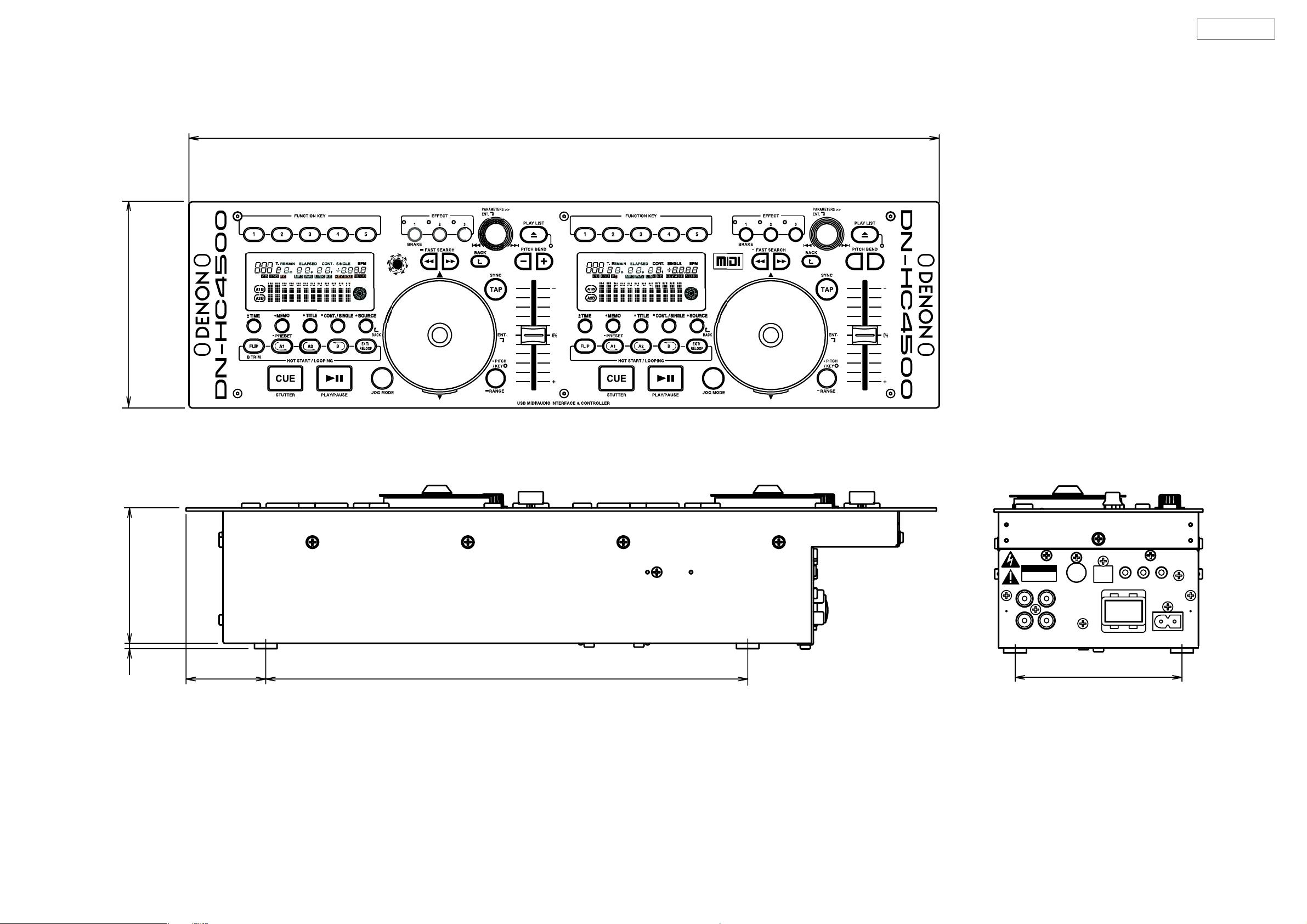
DIMENSION
132.6
DN-HC4500
482.6
87
4.5
51.3
310
%#76+10
4+5-1('.'%64+%5*1%-
&101612'0
LINE OUT 1
L
R
LINE OUT 2
X-CONTROL
USB B
DRIVE
(For use with
˴DENON
˴DN-D4000/4500,
˴BU4500 only)
POWER
ON/OFF
106
FADER 1
FADER 2
AC IN
3
DN-HC4500
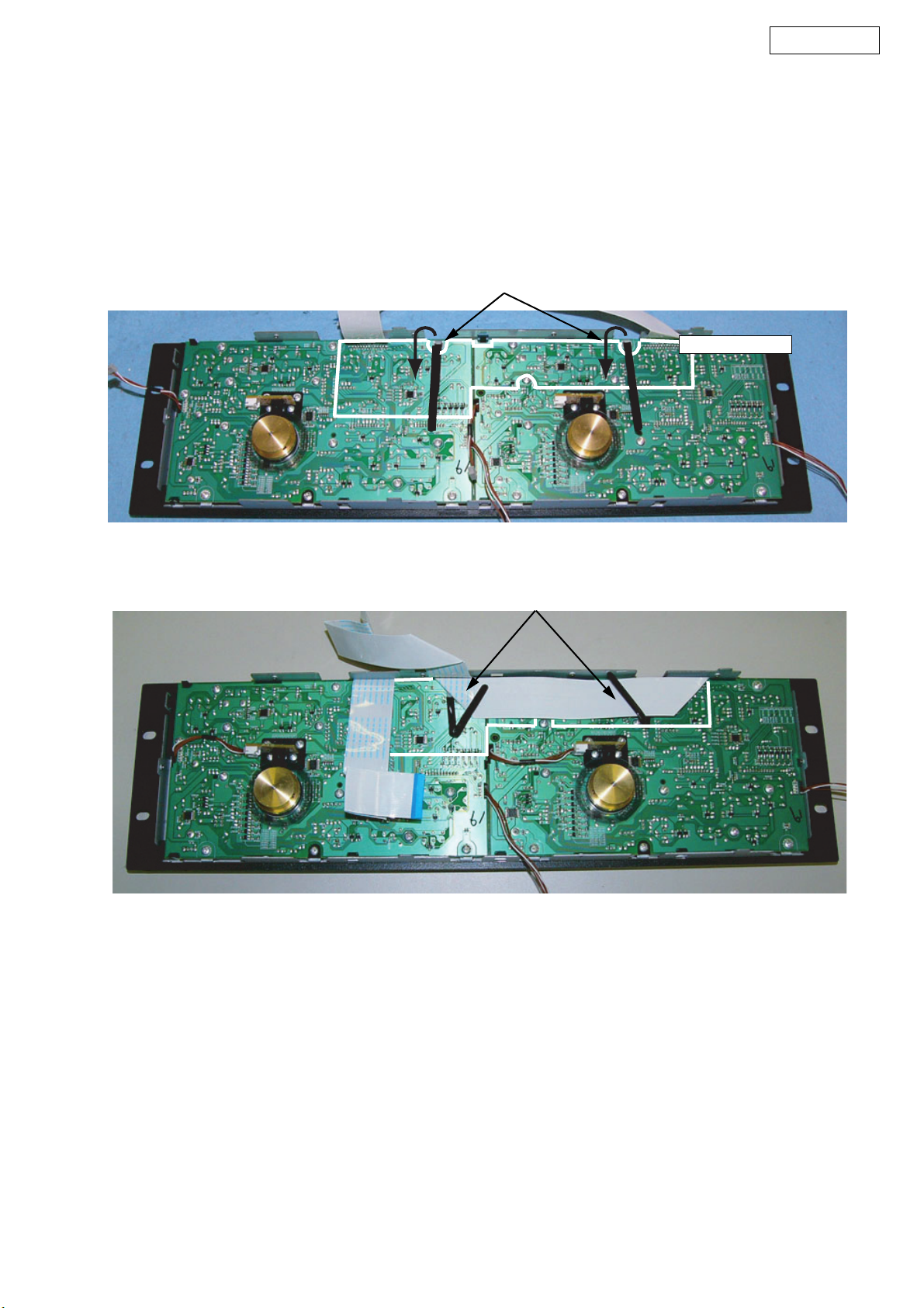
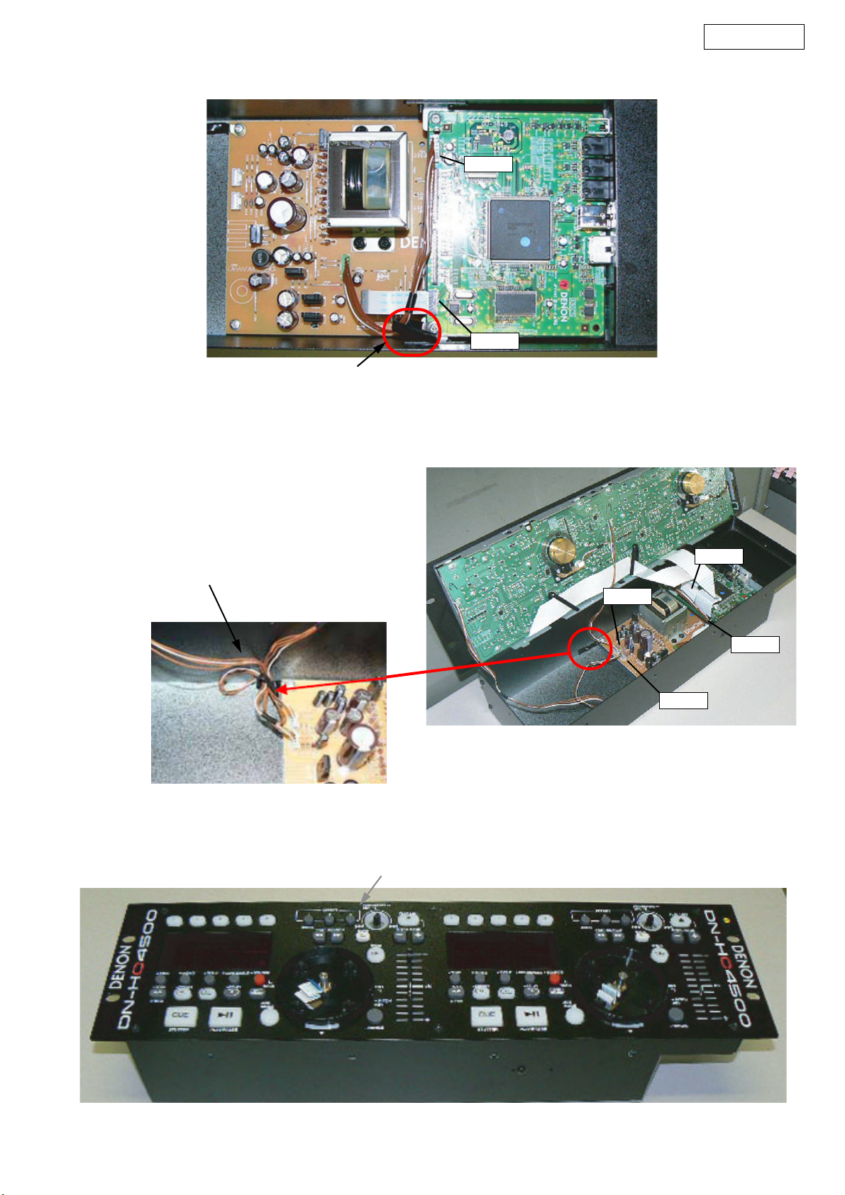
WIRE ARRANGEMENT
If wire bundles are untied or moved to perform adjustment or
parts replacement etc., be sure to rearrange them neatly as
they were originally bundled or placed afterward.
Otherwise, incorrect arrangement can be a cause of noise
generation.
※ Refer to 62~64 page for folding the FFC.
① The cord holder folds as shown on the diagram.
ワイヤー整形図
調整や部品の交換等により、ワイヤー類の結束をはずしたり移
動させた場合には、それらの作業が完了した時点でワイヤーの
整形をおこなってください。正しく整形されてないとノイズ発
生の原因となることがあります。
※ FFC の折り方は 62 〜 64 ページを参照してください。
① コードホルダーを図の様に、折り返す。
①
PRTECT SHEET
PRTECT SHEET
② Fasten the FFC to externals of figure with a cord holder.
② FFC をコードホルダーで図の様に固定する。
②
4
DN-HC4500
③ Fasten the 6P connector with a cord holder.
③
④ Fasten the two4P connectors with a cord holder.
•Fasten the cord not to touch the trans.
•Fold and fasten the cord on the CX042 side..
③ 6P コードをコードホルダーで固定する。
CX061
CX111
④ 4P コード2本をコードホルダーで固定する。
・トランスにコードが接触しない様にする。
・ CX042 側のコードを折り返して固定する。
④
⑤ It coverd with TOP PANEL SUB ASSY.
NOTE:The wire gets caught in TOP PANEL SUB ASSY.
CX271
CX041
CX272
CX042
⑤ TOPPANELSUBASSY をかぶせる。
注意:WIRE を挟み込まない事
⑤
5
DN-HC4500
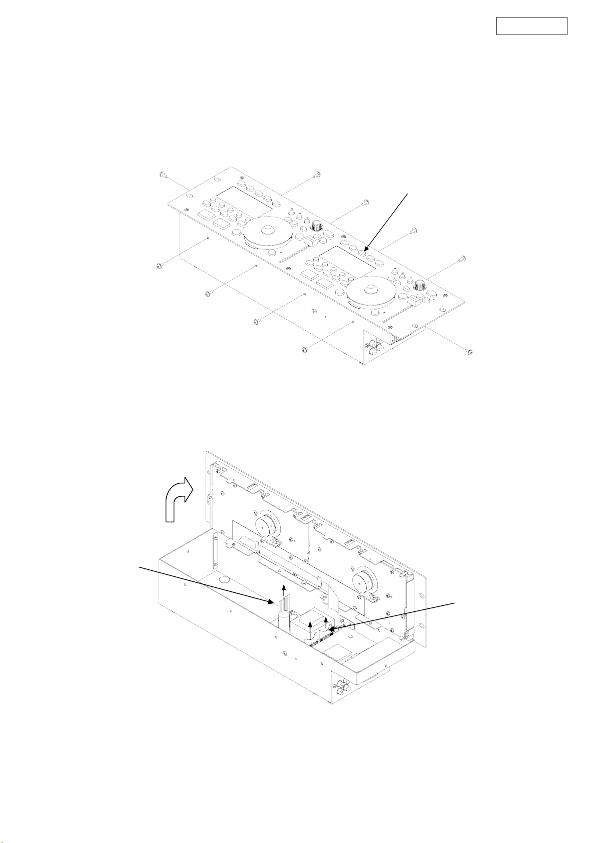
DISASSEMBLY
(Follow the procedure below in reverse order when
reassembling.)
1. Top Panel Unit
(1) Remove 10 side screws with washer and pull up the Top
Panel Unit.
各部のはずしかた
(組み立てるときは、逆の順序でおこなってください。)
1. TopPanelUnit
(1) 側面からねじ 10 本とワッシャーをはずし、Top Panel
Unit を引き出します。
Top Panel Unit
(2) After pull up the Top Panel Unit, turn the back forward
and then pull out the two FFC cable and two wire showed
in the below drawing.
Two wire
(2) 引き出した TopPanelUnit の背面を手前に向け、下図に
示したFFC ケーブル2 本とワイヤー2本を引き抜きます。
Two FFC cable
Notes: Do not pull out aslant to prevent FFC cable damage.
Do not fail to pull AC cord from wall outlet before disconnect the FFC cable and wire.
If AC cord is remained plugged into wall outlet, power is
kept supplied in the unit, which may cause damage.
注意: FFC ケーブルを破損させないために斜めにぬかないで
ください。
FFC ケーブルとワイヤーを抜く前に AC コードをコン
セントから抜いてください。AC コードがコンセント
に接続されていると、Unit に電源が供給され危険で
す。
6
DN-HC4500
SERVICE MODE
1. Turning on the power in the service mode
(1) Turn on the power while pressing the PARAMETERS knob and the B button on either Deck 1 or Deck 2 simultaneously.
The following appears on the VFD segment display section:
Ser v i ce Mode
Func t i on CHK
(2) When the PARAMETERS knob is turned clockwise, the display on the lower tier of the VFD segment display section switches
in the following order: "Function CHK" → "SW Check" → "Panel CHK" → "Touch MEAS".
The display switches in the opposite order when the PARAMETERS knob is turned counterclockwise.
(3) The displayed mode can be selected by pressing the PARAMETERS knob.
※ The service mode switches simultaneously for Deck 1 and Deck 2. When the operations for selecting and executing the dif-
ferent check modes are performed for one deck, they are automatically performed for the other deck as well.
For some items, however, the selection and execution operation must be performed individually for Deck 1 and Deck 2.
(“Audio OUT”, “SW CHECK”, “Panel CHK”, “Touch MEAS”)
2. Function summary
※ Refer to [3. Service mode function table] for details.
(1) Checking the operation of the function (Function CHK)
When the item to be checked is selected from the TOP menu, the device performs the check and settings and the results are
displayed on the VFD segment display section.
• Equipped function
① Setting initialization
② Drive Terminal check
③ Audio signal output
④ Audio Mite check
⑤ Touch initialization
⑥ USB-MIDI command transmission
サービスモードについて
1. サービスモードの立ち上げかた
(1) Deck1 または Deck2 の PARAMETERSノブと B ボタンを同時に押しながら電源を投入する。
VFD のセグメント表示部に以下の文字が表示される。
Se r v i ce Mode
Func t i on CHK
(2) PARAMETERSノブを右に回すと VFD のセグメント表示部の下段の表示が "FunctionCHK" → "SWCheck"→"PanelCHK"→
"TouchMEAS" の順で切り替わる。PARAMETERSノブを左に回すと逆の順で表示が切り替わる。
(3) PARAMETERSノブを押すと、表示されているモードを選択できる。
※ サービスモードは Deck1 と Deck2 が同時に切り替わる。また、各チェックモードの選択及び実行は Deck1 と Deck2 が連
動する。但し、一部の項目では、選択及び実行が Deck1 と Deck2 で個別に操作が必要となる。
("AudioOUT"、"SWCHECK"、"PanelCHK"、"TouchMEAS")
2. 機能概要
※ 詳細は『3. サービスモード機能表』を参照。
(1) 機能動作確認 (FunctionCHK)
TOP メニューから確認したい項目を選択すると、機器がチェックと設定を実行して、結果を VFD のセグメント表示部に表
示する。
・搭載機能
① 設定初期化
② DRIVE 端子確認
③ Audio 信号出力
④ AudioMite 確認
⑤ TOUCH イニシャライズ
⑥ USB-MIDI コマンド送信
(2) Checking the operation of the switches(SW Check)
Once all the switches on the panel surface have been pressed, the switch check mode ends automatically.
(3) Checking the operation of the panel(Panel CHK)
• Checking the operation of the various control elements on the panel surface
① PARAMETERS knob
② JOG disc
③ FADERIN
④ X-Control level
⑤ FADER level
• The functions shown below are always available while in the panel check mode.
⑥ All LEDs lit /LED DIM lit/All LEDs off
(4) Touch measurement(Touch MEAS)
Measurement of the count value when the touch sensor section is not being touched, and measurement and judgment of the
amount of change of the count value when the touch sensor section is being touched.
(2) スイッチ動作確認 (SWCheck)
パネル面の全てのスイッチが押されたら、スイッチチェックモードは自動的に終了する。
(3) パネル動作確認 (PanelCHK)
・パネル面に配置された各種操作子の動作確認
① PARAMETERSノブ
② JOG ディスク
③ フェーダイン
④ X-Control レベル
⑤ フェーダレベル
・以下の機能は、パネルチェックモードにしている間は常に有効である。
⑥ LED 全点灯 /LEDDIM 点灯 /LED 全消灯
(4) タッチ測定 (TouchMEAS)
タッチ検出部の非タッチ時のカウント値の測定と、タッチ時のカウント値の変化量の測定および判定
7
DN-HC4500
3. Service mode function table
Mode Summary Remark
Service Mode TOP
(Service Mode)
Function
check mode
(Function CHK)
Switch check mode
(SW Check)
HC4500 Int, The various parameters are set to the factory defaults.
Drive Check
Audio OUT
Mute Check Switches the hardware's muting circuit on and off.
Touch Init.
USB-MIDI
Turn on the power while pressing the PARAMETERS knob and the B
button on either Deck 1 or Deck 2 simultaneously.
→ Service mode starts
When executed with the drive terminal's Tx and Rx pins connected
externally, the loop-back test is performed.
The device checks whether the transferred and received contents are
the same and the results are displayed.
The device's built-in 24 bit/44.1 kHz sampling frequency 1 kHz/0dB
audio signal is played.
Turn the PARAMETERS knob to select whether the output is on or off,
then press the PARAMETERS knob to execute.
During playback, the letters "OUT" on the VFD segment display section
flash.
Sets the contents of the EPROM built into the touch sensor IC to the
factory defaults.
Sends the MIDI command corresponding to the function selected on
the VFD segment display section.
Turn the PARAMETERS knob clockwise to select the function in the
order shown below.
"CUE" → "PLAY" → "A1" → "A2" → "HOT1"
※ Refer to [3.3. MIDI Ccommands table] for details.
Initially, the VFD is all off, and when a switch is pressed, the corresponding VFD characters lit. → Once all the switches are pressed,
"Complete" is displayed on the VFD segment display section.
※ Refer to [3.1. Switch check mode] for details.
To cancel the service
mode, turn the power
off.
Press the BACK button to return to the top
level of the Function
check mode.
Press the PARAMETERS knob to return to
the top level of the
Switch check mode.
3. サービスモード機能表
モード 概要 備考
サービスモード TOP
(ServiceMode)
HC4500Int, 各種パラメータを工場出荷状態に設定
DriveCheck
AudioOUT
Function
チェックモード
(FunctionCHK)
スイッチチェックモード
(SWCheck)
MuteCheck ハードウェアのミュート回路の ON/OFF を切り替える。
TouchInit.
USB-MIDI
Deck1 または Deck2 の PARAMETERSノブと B ボタンを同時に押
しながら電源を投入する。
→サービスモードが起動
機器外部で Drive 端子の Tx-Rx 間を接続した状態で実行すると、
ループバックテストを実施する
送信内容と受信内容が等しいかどうかを確認して、結果を表示す
る。
機器に内蔵されている 24bit/44.1kHz サンプリングの 1kHz/0dB
のオーディオ信号を再生する。
PARAMETERSノブを回して出力 ON/OFF 選択し、PARAMETERS
ノブを押して実行する。
再生中は VFD のセグメント表示部の "OUT" の文字が点滅する。
タッチセンサ IC に内蔵された EPROM の内容を工場出荷時の状態
に設定する。
VFDのセグメント表示部で選択された機能に相当する MIDI コマンド
を送信する。
PARAMETERS ノブを時計回りに回すと、以下の順で機能を選択
できる。
"CUE" → "PLAY" → "A1" → "A2" → "HOT1"
※ 詳細は、『3.3.MIDI コマンド表』を参照
初期状態で VFD は全消灯し、スイッチを押すと該当する VFD の
キャラクタが点灯する→全てのスイッチを押すと、VFD のセグメ
ント表示部に "Complete" が表示される。
※ 詳細は、『3.1.スイッチチェックモード (SWCheck)』を参照
モードを解除するには電
源 OFF にする。
BACK ボタンの押すと
Function チェックモード
の TOP 階層に戻る。
PARAMETERSノ ブを押す
とスイッチチェックモー
ドの TOP 階層に戻る。
8
DN-HC4500
Mode Summary Remark
Panel check mode
(Panel CHK)
Touch measurement mode
(Touch MEAS)
※ Display of the status and results of the various control elements on
the panel surface and external input from the side panel
• PARAMETERS knob
The segment on the right side of the "P" column at the upper left of
the VFD segment display section toggles between white and black
each time the PARAMETERS knob is pressed.
When the PARAMETERS knob is turned, -> (clockwise) or <- (counterclockwise) is displayed.
•JOG disc
When a touch is detected: The center of the scratch marker at the
bottom right of the VFD display section lights.
The left and right display sections of the scratch marker light according to the direction of rotation.
The jog rev count detection result is displayed on the frame count display section.
• PITCH slider
The pitch signal's AD conversion value is displayed on the pitch display section.
The center tap value is displayed in three digits on the track number
display section.
<Spec>
Central tap display value : CENTER = 512 ± 77
Pitch signal display value
• MAX value : 1018 or more
• Central click position : PITCH = CENTER ± 25
• MIN value : 6 or less
• FADERIN
The segment display sections at the sides of FC and FP on the VFD
segment display section are displayed as ■ while the CUE and
PLAY fade-in signals are being detected, respectively.
• X-Control
The AD conversion values of the X-Fade and CH signals are displayed at the sides of XF and XC on the VFD segment display section.
• XF display value
• MAX value : 1010 or more
• MIN value : 10 or less
• XC display value : 0 fixation → Future
• LED/VFD light/off
When the TAP button is pressed, the display toggles in the following
order: All LEDs lit + VFD all lit → LED DIM lit + VFD off → LED off +
normal VFD display
※This function is always available while in the "Panel CHK" mode.
The count value detected by the touch sensor IC is displayed on the
VFD.
OK if the difference between the count value when not being touched
and the count value when touched is 50 or greater.
OK if the count value when not being touched is between the range of
100 and 300.
※ Refer to [3.2. Touch measurement mode] for details.
Press the BACK and
PLAYLIST buttons to
return to the top level
of the panel check
mode.
Press the BACK and
PLAYLIST buttons to
return to the top level
of the Touch measurement mode.
モード 概要 備考
パネルチェックモード
(PanelCHK)
タッチ計測モード
(TouchMEAS)
※ パネル面に配置された各種操作子、およびサイドパネルから
の外部入力の状態と結果を表示
・ PARAMETERSノブ
PARAMETERS ノブを押す毎に、VFD のセグメント表示部の左上
の「P」欄の右隣のセグメントを白⇔黒でトグル表示する。
PARAMETERSノブを回転させると、回転方向に応じて、->(右
回転)、<-(左回転)を表示。
・ JOG ディスク
タッチ検出時 :
VFD の表示部の右下にあるスクラッチマーカの中心が点灯
回転方向に応じて、スクラッチマーカの左右の表示部が点灯
JOG の回転数の検出結果を、フレームカウントの表示部分に表
示
・ ピッチスライダ
ピッチの表示部にピッチ信号の AD 変換値を表示
センタータップ値はトラックナンバーの表示部にて 3 桁で表示
<スペック>
センタータップ表示値 :CENTER=512 ± 77
ピッチ信号表示値
・ 最大値 :1018 以上
・ センタークリック位置 :PITCH=CENTER ± 25
・ 最小値 :6 以下
・ フェーダイン
CUE、PLAY のフェーダイン信号を検出している間は、VFD の
セグメント表示部のそれぞれ FC、FP の隣のセグメント表示部
を■で表示する。
・ X-Control
X-Fade、CH の各信号の AD 変換値を VFD のセグメント表示部の
XF、XC の隣に表示する。
・ XF 表示値
最大値 :1010 以上
最小値 :10 以下
XC 表示値 :0 固定→ Future
・ LED/VFD 点灯 / 消灯
TAP ボタンを押すと、LED 全点灯 +VFD 全点灯→ LEDDIM 点灯
+VFD 消灯→ LED 消灯 +VFD 通常表示の順番でトグル動作する。
※ PanelCHK モード中は、本機能が常に有効。
タッチセンサ IC が検出したカウント値を VFD に表示する。
非タッチ時のカウント値とタッチ時のカウント値の差分が50以上で
あれば OK
非タッチ時のカウント値が 100 以上、300 以下の範囲内であれば
OK
※ 詳細は、『3.2.タッチ測定モード (TouchMEAS)』を参照
BACK または PLAYLIST ボタ
ンを押すとパネルチェック
モードの TOP 階層に戻る。
BACKボタンまたはPLAYLIST
ボタンを押すと
モード
の TOP 階層に戻る。
タッチ計測
9
DN-HC4500
3.1. Switch check mode (SW Check)
(1) All the VFD characters are turned off.
The following characters are assigned to the 12 places of the VFD segment display section:
Upper P R F B
Lower T C P
(2) When each switch is pushed
HOT1~HOT5 → The numbers of the various buttons light on the track number display section and in the five places
of the minutes counter display section.
EFX1~3 → EFX1-2: The numbers of the various buttons light on the seconds counter display section; EFX3:
The numbers of the buttons light on the frame counter display section.
PLAYLIST → "P" is displayed in the fifth place of the
Fast Search → "R" is displayed in the third place of the upper tier for the reverse mode, "F" is displayed in the fourth
place of the upper tier for the forward mode.
BACK → "B" is displayed in the six place of the upper tier.
PITCH BEND → " + " is displayed in the eighth place of the upper tier, " − " is displayed in the fifth place of the
tier.
TIME → "REMAIN" indicator is light.
MEMO → "MEMO" indicator is light.
TITLE → "T" is displayed in the first place of the
CONT → "CONT" indicator is light.
SOURCE → "CD" indicator is light.
FLIP → The "(" for A1 and A2 on the left side of the VFD display section light simultaneously.
A1, A2 → The ”A1” or “A2” on the left side of the VFD display section light respectively.
B → The "B" for A1 and A2 on the left side of the VFD display section light simultaneously.
EXIT → The ")" for A1 and A2 on the left side of the VFD display section light simultaneously.
CUE, PLAY → "C" is displayed in the third place of the lower tier for the CUE mode, “P” is displayed in the ninth
place of the upper tier for the PLAY mode.
JOG MODE → The center of the scratch mark is light.
PITCH → "KEY ADJ." indicator is light.
TAP → "BPM" indicator is light.
−+
lower tier.
lower tier.
lower
3.1. スイッチチェックモード(SWCheck)
(1) VFD のキャラクタを全消灯する
VFD のセグメント表示部の 12 桁に以下の文字を割り当てる。
上段
下段
(2) 各スイッチを押すと
HOT1 〜 HOT5 →トラックナンバー表示部、及び分カウンタ表示部の 5 桁に各々のボタンの数字を点灯する。
EFX1 〜 3 → EFX1-2:秒カウンタ表示部にそれぞれのボタンの数字を表示、EFX3:フレームカウンタ表示部に
PLAYLIST →上段 1 桁目に "P" を表示する。
FastSearch →リバースは上段3桁目に "R" を表示し、フォワードは上段4桁目に "F" を表示する。
BACK →上段 6 桁目に "B" を表示する。
PITCHBEND →上段 8 桁目に " − " を表示し、上段 9 桁目" + " を表示する。
TIME → "REMAIN" インジケータを点灯する。
MEMO → "MEMO" インジケータを点灯する。
TITLE →下段 1 桁目に "T" を表示する。
CONT → "CONT" インジケータを点灯する。
SOURCE → "CD" インジケータを点灯する。
FLIP → VFD 表示部の左側にある A1 及び A2 の "(" を同時に点灯する。
A1、A2 → VFD 表示部の左側にある "A1"、"A2" を各々点灯する。
B → VFD 表示部の左側にある A1 及び A2 の "B" を同時に点灯する。
EXIT → VFD 表示部の左側にある A1 及び A2 の)を同時に点灯する。
CUE、PLAY → CUE は下段 3 桁目に "C" を表示し、PLAY は下段 5 桁目 "P" を表示する。
JOGMODE →スクラッチマークの中心を点灯する。
PITCH → "KEYADJ." インジケータを点灯する。
TAP → "BPM" インジケータを点灯する。
(3) 全てのスイッチが押されると、VFD のセグメント表示部の下段に "Complete" と表示される。(両 Deck)
両 Deck 共に、"Complete" が表示された状態で、任意のスイッチを押すと、スイッチチェックモードの TOP 階層に戻る。
PRFB
TCP
ボタンの数字を表示する。
−+
(3) Once all the switches have been pressed, "Complete" is displayed on the lower tier of the VFD segment display sec-
tion.(both decks)
For both decks, press any switch while "Complete" is displayed to return to the top level of the switch check mode.
3.2. Touch measurement mode(Touch MEAS)
(1) All the VFD characters are turned off.
The following appears on the VFD segment display section:(Count value display mode)
TP_***RT_***
BM_***LT_***
*** : Current touch count value is displayed.
(TP : TOP, BM : BOTTOM, RT : RIGHT, LT : LEFT)
The average of the count values acquired for the first four times measurements are made after this mode is set is calculated
and used as the reference value.
(2) Turn the PARAMETERS knob one click to switch the display on the VFD segment display section as shown below. (Differ-
ence display mode)
TP
BM
*** : (Standard value) - (Current touch count value) is displayed.
Now, turn the PARAMETERS knob one click to switch to the count display mode in (1).
(3) The center of the scratch mark lights if the difference of the count value calculated with any one of the four sensors above,
below and to the sides of the disc during the touch measurement mode is 50 or greater.
(4) When the PARAMETERS knob is pressed, the average of the count value acquired for the first four times measurements
are made after the PARAMETERS knob is pressed is held on the display.
(5) Press the PARAMETERS knob again to return to the count display mode in (1).
(6) Press the BACK and PLAYLIST buttons to return to the top level of the Touch measurement mode.
***RT
▲
***LT
▲
***
▲
***
▲
3.2. タッチ測定モード (TouchMEAS)
(1) VFD のキャラクタを全消灯する。
VFD セグメント表示部の 12 桁に以下を表示する(カウント値表示モード)
TP_* * *RT_***
BM_***LT_* * *
***:現在のタッチカウント値を表示する。
(TP:TOP、BM:BOTTOM、RT:RIGHT、LT:LEFT)
本モードに入ってから最初の 4 回の測定で取得したカウント値の平均を算出して、基準値とする。
(2) PARAMETERSノブを1クリック回すと、VFD のセグメント表示部の表示が以下の表示に切り替わる。(差分表示モード)
TP
BM
***:( 基準値 )-( 現在のタッチカウント値 ) を表示する。
この状態で PARAMETERSノブを1クリック回すと、(1) のカウント表示モードに切り替わる。
(3) タッチ測定モード中は DISC の上下左右にある 4 つのセンサーの内、いずれかのセンサーで算出したカウント値の差分
値が 50 以上の時、スクラッチマークの中心が点灯する。
(4) PARAMETERSノブを押すと、PARAMETERSノブを押した後の 4 回の測定で取得したカウント値の平均値をホールド状態
で表示する。
(5) 再度、PARAMETERSノブを押すと、(1) のカウント値表示モードに戻る。
(6) PLAYLIST または BACK ボタンを押すと、タッチ測定モードの TOP 階層に戻る。
***RT
▲
***LT
▲
***
▲
***
▲
10
DN-HC4500
3.3. MIDI COMMANDS
(1) Data transmission
The panel operation data is transmitted by MIDI command, as per the table below.
● Send command to PC
items
1 Playlist
2JOG mode
3Pitch/KEY
4TAP
5 Pitch Bend+
6 Pitch Bend-
7 Fast search+
8 Fast search-
9 EFX1/ECHO/LOOP
10 EFX2/FLANGER
11 EFX3/FILTER
12 HOT1
13 HOT2
14 HOT3
15 HOT4
16 HOT5
17 TIME/TOTAL
18 MEMO/PRESET
19 TITLE
20 CONT./SINGLE
21 Parameters KNOB SW
22 BACK
23 SOURCE mode
24 FLIP
25 A1
26 A2
27 B
28 EXIT/Reloop
29 Cue
30 Play
31 JOG UP
32 JOG DOWN
33 JOG LEFT
34 JOG RIGHT
35 Jogwheel touch
36 Preset Mode
37 D4500 Cont. mode
38 Jogwheel fwd/rev 0xBn 0x51
39 X-Control fader
Parameters KNOB
40
Increment/Decrement
41 Pitch Slider 0xEn 0xllh (LSB) 0xmmh (MSB) Pitch bend change
Command Number Value
SW ON : 0x9n
SW OFF : 0x8n
↑
↑
↑
↑
↑
↑
↑
↑
↑
↑
↑
↑
↑
↑
↑
↑
↑
↑
↑
↑
↑
↑
↑
↑
↑
↑
↑
↑
↑
↑
↑
↑
↑
↑
SW ON : 0x9n
SW OFF : 0x8n
↑
↑
↑
MIDI command
0x02
0x04
0x05
0x07
0x08
0x09
0x10
0x11
0x12
0x13
0x14
0x17
0x18
0x19
0x20
0x21
0x23
0x24
0x25
0x26
0x28
0x30
0x31
0x36
0x37
0x38
0x39
0x40
0x42
0x43
0x47
0x48
0x49
0x50
0x51
0x52
0x53
0x53
0x54
-100% : 0x7F7F (MSB/LSB)
0% : 0x4000 (MSB/LSB)
+100% : 0x0000 (MSB/LSB)
SW ON : 0x40
SW OFF : 0x00
↑↑
↑↑
↑↑
↑↑
↑↑
↑↑
↑↑
↑↑
↑↑
↑↑
↑↑
↑↑
↑↑
↑↑
↑↑
↑↑
↑↑
↑↑
↑↑
↑↑
↑↑
↑↑
↑↑
↑↑
↑↑
↑↑
↑↑
↑↑
↑↑
↑↑
↑↑
↑↑
↑↑
↑↑
SW ON : 0x40
SW OFF : 0x00
↑↑
Reverse 0x3F ~ 0x01
Foward 0x41 ~ 0x7F
slow → fast
※ relative data
0x00 (min) → 0x7F
(max)
"Increment : 0x00
Decrement : 0x7F"
Message type
Note ON/OFF
Note ON/OFF
Control change
3.3. MIDI コマンド
(1) 送信データ
パネル操作データの送信は、以下の表に従い、MIDI コマンドを送信する。
● PC にコマンドを送る
items
1 Playlist
2 JOG mode
3 Pitch/KEY
4TAP
5 Pitch Bend+
6 Pitch Bend-
7 Fast search+
8 Fast search-
9 EFX1/ECHO/LOOP
10 EFX2/FLANGER
11 EFX3/FILTER
12 HOT1
13 HOT2
14 HOT3
15 HOT4
16 HOT5
17 TIME/TOTAL
18 MEMO/PRESET
19 TITLE
20 CONT./SINGLE
21 Parameters KNOB SW
22 BACK
23 SOURCE mode
24 FLIP
25 A1
26 A2
27 B
28 EXIT/Reloop
29 Cue
30 Play
31 JOG UP
32 JOG DOWN
33 JOG LEFT
34 JOG RIGHT
35 Jogwheel touch
36 Preset Mode
37 D4500 Cont. mode
38 Jogwheel fwd/rev 0xBn 0x51
↑
↑
39 X-Control fader
Parameters KNOB
40
Increment/Decrement
41 Pitch Slider 0xEn 0xllh (LSB) 0xmmh (MSB) Pitch bend change
Command Number Value
SW ON : 0x9n
SW OFF : 0x8n
↑
↑
↑
↑
↑
↑
↑
↑
↑
↑
↑
↑
↑
↑
↑
↑
↑
↑
↑
↑
↑
↑
↑
↑
↑
↑
↑
↑
↑
↑
↑
↑
↑
↑
SW ON : 0x9n
SW OFF : 0x8n
↑
↑
↑
MIDI command
0x02
0x04
0x05
0x07
0x08
0x09
0x10
0x11
0x12
0x13
0x14
0x17
0x18
0x19
0x20
0x21
0x23
0x24
0x25
0x26
0x28
0x30
0x31
0x36
0x37
0x38
0x39
0x40
0x42
0x43
0x47
0x48
0x49
0x50
0x51
0x52
0x53
0x53
0x54
-100% : 0x7F7F (MSB/LSB)
0% : 0x4000 (MSB/LSB)
+100% : 0x0000 (MSB/LSB)
SW ON : 0x40
SW OFF : 0x00
↑↑
↑↑
↑↑
↑↑
↑↑
↑↑
↑↑
↑↑
↑↑
↑↑
↑↑
↑↑
↑↑
↑↑
↑↑
↑↑
↑↑
↑↑
↑↑
↑↑
↑↑
↑↑
↑↑
↑↑
↑↑
↑↑
↑↑
↑↑
↑↑
↑↑
↑↑
↑↑
↑↑
↑↑
SW ON : 0x40
SW OFF : 0x00
↑↑
Reverse 0x3F ~ 0x01
Foward 0x41 ~ 0x7F
slow → fast
※ relative data
0x00 (min) → 0x7F
(max)
"Increment : 0x00
Decrement : 0x7F"
Message type
Note ON/OFF
Note ON/OFF
Control change
↑
↑
n = MIDI CH
n = MIDI CH
11
DN-HC4500
(2) Data reception
LED data reception
The panel operation data is transmitted by MIDI command, as per the table below.
● Receive command for LED
items
LED 0xBn
1 Playlist 0x02
2 Pitch match LED 0x04
3 JOG mode Green 0x05
4 JOG mode Orange 0x06
5 Pitch/KEY Green 0x07
6 Pitch/KEY Orange 0x08
7 TAP Green 0x09
8 TAP Orange 0x0A
9 EFX1/ECHO/LOOP RED 0x0B
10 EFX1 Green 0x0C
11 EFX2/FLANGER RED 0x0D
12 EFX2 Green 0x0E
13 EFX3/FILTER RED 0x0F
14 EFX3 Green 0x10
15 HOT1 0x11
16 HOT1 Dimmer 0x12
17 HOT2 0x13
18 HOT2 Dimmer 0x14
19 HOT3 0x15
20 HOT3 Dimmer 0x16
21 HOT4 0x17
22 HOT4 Dimmer 0x18
23 HOT5 0x19
24 HOT5 Dimmer 0x1A
25 Parameter KNOB 0x1E
26 A1 0x24
27 A1 Dimmer 0x3C
28 A2 0x25
29 A2 Dimmer 0x3D
30 Cue 0x26
31 Play 0x27
32 Jogwheel 0x3B
33 Pitch slider request
34 X-Control fader request
Command Number Value
MIDI command
ON TRG : 0x4A
OFF TRG : 0x4B
Blink ON TRG : 0x4C
only Use 0x4A
(request TRG)
only Use 0x4A
(request TRG)
n = MIDI CH
↓
0x3C
0x3D
Message type Notes
Control Change
DN-HC4500 return
pitch slider position
DN-HC4500 return
XControl fader position
(2) 受信データ
LED 受信データ
パネルの LED は以下の表に従い MIDI コマンドでオン、オフ、ブリンクが設定できる 7。
● LED のコマンドを受け取る
items
LED 0xBn
1 Playlist 0x02
2 Pitch match LED 0x04
3 JOG mode Green 0x05
4 JOG mode Orange 0x06
5 Pitch/KEY Green 0x07
6 Pitch/KEY Orange 0x08
7 TAP Green 0x09
8 TAP Orange 0x0A
9 EFX1/ECHO/LOOP RED 0x0B
10 EFX1 Green 0x0C
11 EFX2/FLANGER RED 0x0D
12 EFX2 Green 0x0E
13 EFX3/FILTER RED 0x0F
14 EFX3 Green 0x10
15 HOT1 0x11
16 HOT1 Dimmer 0x12
17 HOT2 0x13
18 HOT2 Dimmer 0x14
19 HOT3 0x15
20 HOT3 Dimmer 0x16
21 HOT4 0x17
22 HOT4 Dimmer 0x18
23 HOT5 0x19
24 HOT5 Dimmer 0x1A
25 Parameter KNOB 0x1E
26 A1 0x24
27 A1 Dimmer 0x3C
28 A2 0x25
29 A2 Dimmer 0x3D
30 Cue 0x26
31 Play 0x27
32 Jogwheel 0x3B
33 Pitch slider request
34 X-Control fader request
Command Number Value
MIDI command
ON TRG : 0x4A
OFF TRG : 0x4B
Blink ON TRG : 0x4C
only Use 0x4A
(request TRG)
only Use 0x4A
(request TRG)
↓
0x3C
0x3D
n = MIDI CH
Message type Notes
Control Change
DN-HC4500 return
pitch slider position
DN-HC4500 return
XControl fader position
12
DN-HC4500
VFD symbol data reception
The Various Vfd Symbols Can Be Set To On, Off Or Blinking, As Per The Table Below.
● Receive command for VFD Symbol
items
VFD Symbol 0xBn
1T.
2 REMAIN
3 ELAPSED
4CONT.
5SINGLE
6 BPM
7m
8s
9f
10 Pitch dot Right
11 Pitch dot center
12 Pitch dot left
13 MP3
14 WAV
15 KB
16 KEY ADJ.
17 MEMO
18 ( : A1 side
19 ( : A2 side
20 ) : A1 side
21 ) : A2 side
22 A1
23 A2
24 B : A1 side
25 B : A2 side
26 Scratch Ring out side
27 Scratch Ring in side
28 Touch dot
29 Track Position Blink only Use 0x4F/0x4E
30 Scratch Position 1 (Top right) only Use 0x4D/0x4E
31 Scratch Position 2 only Use 0x4D/0x4E
32 Scratch Position 3 only Use 0x4D/0x4E
33 Scratch Position 4 only Use 0x4D/0x4E
34 Scratch Position 5 only Use 0x4D/0x4E
35 Scratch Position 6 only Use 0x4D/0x4E
36 Scratch Position 7 only Use 0x4D/0x4E
37 Scratch Position 8 only Use 0x4D/0x4E
38 Scratch Position 9 only Use 0x4D/0x4E
39 Scratch Position 10 only Use 0x4D/0x4E
Command Number Value
MIDI command
ON TRG : 0x4D
OFF TRG : 0x4E
Blink ON TRG : 0x4F
↓
0x01
0x02
0x03
0x04
0x05
0x06
0x07
0x08
0x09
0x0A
0x0B
0x0C
0x10
0x11
0x13
0x14
0x15
0x16
0x17
0x18
0x19
0x1A
0x1B
0x1C
0x1D
0x1E
0x1F
0x20
0x21
0x22
0x23
0x24
0x25
0x26
0x27
0x28
0x29
0x2A
0x2B
Message type
Control Change
VFD シンボルデータ受信
VFD の各種シンボルは以下の表に従いオン、オフ、ブリンクが設定できる。
● VFD シンボルのコマンドを受け取る
items
VFD Symbol 0xBn
1T.
2 REMAIN
3 ELAPSED
4CONT.
5SINGLE
6 BPM
7m
8s
9f
10 Pitch dot Right
11 Pitch dot center
12 Pitch dot left
13 MP3
14 WAV
15 KB
16 KEY ADJ.
17 MEMO
18 ( : A1 side
19 ( : A2 side
20 ) : A1 side
21 ) : A2 side
22 A1
23 A2
24 B : A1 side
25 B : A2 side
26 Scratch Ring out side
27 Scratch Ring in side
28 Touch dot
29 Track Position Blink only Use 0x4F/0x4E
30 Scratch Position 1 (Top right) only Use 0x4D/0x4E
31 Scratch Position 2 only Use 0x4D/0x4E
32 Scratch Position 3 only Use 0x4D/0x4E
33 Scratch Position 4 only Use 0x4D/0x4E
34 Scratch Position 5 only Use 0x4D/0x4E
35 Scratch Position 6 only Use 0x4D/0x4E
36 Scratch Position 7 only Use 0x4D/0x4E
37 Scratch Position 8 only Use 0x4D/0x4E
38 Scratch Position 9 only Use 0x4D/0x4E
39 Scratch Position 10 only Use 0x4D/0x4E
Command Number Value
MIDI command
ON TRG : 0x4D
OFF TRG : 0x4E
Blink ON TRG : 0x4F
↓
0x01
0x02
0x03
0x04
0x05
0x06
0x07
0x08
0x09
0x0A
0x0B
0x0C
0x10
0x11
0x13
0x14
0x15
0x16
0x17
0x18
0x19
0x1A
0x1B
0x1C
0x1D
0x1E
0x1F
0x20
0x21
0x22
0x23
0x24
0x25
0x26
0x27
0x28
0x29
0x2A
0x2B
Message type
Control Change
13
DN-HC4500
items
Command Number Value
VFD Symbol 0xBn
40 Scratch Position 11 only Use 0x4D/0x4E
41 Scratch Position 12 only Use 0x4D/0x4E
42 Scratch Position 13 only Use 0x4D/0x4E
43 Scratch Position 14 only Use 0x4D/0x4E
44 Scratch Position 15 only Use 0x4D/0x4E
45 Scratch Position 16 (Bottom) only Use 0x4D/0x4E
46 Scratch Position 17 only Use 0x4D/0x4E
47 Scratch Position 18 only Use 0x4D/0x4E
48 Scratch Position 19 only Use 0x4D/0x4E
49 Scratch Position 20 only Use 0x4D/0x4E
50 Scratch Position 21 only Use 0x4D/0x4E
51 Scratch Position 22 only Use 0x4D/0x4E
52 Scratch Position 23 only Use 0x4D/0x4E
53 Scratch Position 24 only Use 0x4D/0x4E
54 Scratch Position 25 only Use 0x4D/0x4E
55 Scratch Position 26 only Use 0x4D/0x4E
56 Scratch Position 27 only Use 0x4D/0x4E
57 Scratch Position 28 only Use 0x4D/0x4E
58 Scratch Position 29 only Use 0x4D/0x4E
59 Scratch Position 30 only Use 0x4D/0x4E
60 Scratch Position 31 only Use 0x4D/0x4E
61 Scratch Position 32 (Top) only Use 0x4D/0x4E
MIDI command
ON TRG : 0x4D
OFF TRG : 0x4E
Blink ON TRG : 0x4F
↓
0x2C
0x2D
0x2E
0x2F
0x30
0x31
0x32
0x33
0x34
0x35
0x36
0x37
0x38
0x39
0x3A
0x3B
0x3C
0x3D
0x3E
0x3F
0x40
0x41
Message type
Control Change
n = MIDI CH
※ Track Position Blink” sets blinking of the entire track position display segment on or off.
n = MIDI CH
※ TrackPositionBlink はトラックポジション表示セグメント全体のブリンク点灯の ON/OFF を設定する。
14
DN-HC4500
VFD parameter data reception
The time-related display and segment display can be set by MIDI command, as per the table below.
● Receive command for VFD Parameter
Items
VFD Parameter
1 Tr number MSB 0xBn 0x40
2 Tr number LSB
3 Time mini
4Time sec
5 Time frame
6Pitch POL
7Pitch MSB
8Pitch LSB
9 Track Position
10 Segment 1-1 MSB
11 Segment 1-2 MSB
12 Segment 1-3 MSB
13 Segment 1-4 MSB
14 Segment 1-5 MSB
15 Segment 1-6 MSB
16 Segment 1-7 MSB
17 Segment 1-8 MSB
18 Segment 1-9 MSB
19 Segment 1-10 MSB
20 Segment 1-11 MSB
21 Segment 1-12 MSB
22 Segment 1-1 LSB
23 Segment 1-2 LSB
24 Segment 1-3 LSB
25 Segment 1-4 LSB
26 Segment 1-5 LSB
27 Segment 1-6 LSB
28 Segment 1-7 LSB
29 Segment 1-8 LSB
30 Segment 1-9 LSB
31 Segment 1-10 LSB
32 Segment 1-11 LSB
33 Segment 1-12 LSB 0xBn 0x2D 0x00 ~ 0x0F Control Change
34 Segment 2-1 MSB
35 Segment 2-2 MSB
36 Segment 2-3 MSB
37 Segment 2-4 MSB
38 Segment 2-5 MSB
Command Number Value
↑
↑
↑
↑
↑
↑
↑
↑
↑
↑
↑
↑
↑
↑
↑
↑
↑
↑
↑
↑
↑
↑
↑
↑
↑
↑
↑
↑
↑
↑
↑
↑↑
↑↑
↑↑
↑↑
↑↑
MIDI command
100-109 : “-0” to”-9”
110 : “-”, 111 : “ "
0x41
0x42
0x43
0x44
0x45
0x46
0x47
0x48 normal
0x49 reverse
0x01 0x00 ~ 0x0F
0x02
0x03
0x04
0x05
0x07
0x08
0x09
0x0A
0x0B
0x0C
0x0D
0x21
0x22
0x23
0x24
0x25
0x27
0x28
0x29
0x2A
0x2B
0x2C
Message Type
0-99
Control Change
↑↑
↑↑
↑↑
↑↑
" “ 0x00
“+” 0x01
“-” 0x02"
↑↑
↑↑
0-100%
↑↑
↑↑
↑↑
↑↑
↑↑
↑↑
↑↑
↑↑
↑↑
↑↑
↑↑
↑↑
↑↑
↑↑
↑↑
↑↑
↑↑
↑↑
↑↑
↑↑
↑↑
↑↑
0x0E
0x0F
0x10
0x11
0x12
VFD パラメータデータ受信
時間関連表示とセグメント表示部は以下の表に従い、MIDI コマンドで設定できる。
● VFD バラメーターのコマンドを受け取る
Items
VFD Parameter
1 Tr number MSB 0xBn 0x40
2 Tr number LSB
3 Time mini
4Time sec
5 Time frame
↑
↑
↑
↑
↑
↑
↑
↑
6Pitch POL
7Pitch MSB
8Pitch LSB
9 Track Position
10 Segment 1-1 MSB
11 Segment 1-2 MSB
12 Segment 1-3 MSB
13 Segment 1-4 MSB
14 Segment 1-5 MSB
15 Segment 1-6 MSB
16 Segment 1-7 MSB
17 Segment 1-8 MSB
18 Segment 1-9 MSB
19 Segment 1-10 MSB
20 Segment 1-11 MSB
21 Segment 1-12 MSB
22 Segment 1-1 LSB
23 Segment 1-2 LSB
24 Segment 1-3 LSB
25 Segment 1-4 LSB
26 Segment 1-5 LSB
27 Segment 1-6 LSB
28 Segment 1-7 LSB
29 Segment 1-8 LSB
30 Segment 1-9 LSB
31 Segment 1-10 LSB
32 Segment 1-11 LSB
33 Segment 1-12 LSB 0xBn 0x2D 0x00 ~ 0x0F Control Change
34 Segment 2-1 MSB
35 Segment 2-2 MSB
36 Segment 2-3 MSB
37 Segment 2-4 MSB
38 Segment 2-5 MSB
Command Number Value
↑
↑
↑
↑
↑
↑
↑
↑
↑
↑
↑
↑
↑
↑
↑
↑
↑
↑
↑
↑
↑
↑
↑
↑
↑
↑
↑
↑
↑
↑
↑
↑↑
↑↑
↑↑
↑↑
↑↑
MIDI command
100-109 : “-0” to”-9”
110 : “-”, 111 : “ "
0x41
0x42
0x43
0x44
0x45
0x46
0x47
0x48 normal
0x49 reverse
0x01 0x00 ~ 0x0F
0x02
0x03
0x04
0x05
0x07
0x08
0x09
0x0A
0x0B
0x0C
0x0D
0x21
0x22
0x23
0x24
0x25
0x27
0x28
0x29
0x2A
0x2B
0x2C
Message Type
0-99
Control Change
↑↑
↑↑
↑↑
↑↑
" “ 0x00
“+” 0x01
“-” 0x02"
↑↑
↑↑
0-100%
↑↑
↑↑
↑↑
↑↑
↑↑
↑↑
↑↑
↑↑
↑↑
↑↑
↑↑
↑↑
↑↑
↑↑
↑↑
↑↑
↑↑
↑↑
↑↑
↑↑
↑↑
↑↑
0x0E
0x0F
0x10
0x11
0x12
↑
↑
↑
↑
↑
↑
↑
↑
15
DN-HC4500
39 Segment 2-6 MSB
40 Segment 2-7 MSB
41 Segment 2-8 MSB
42 Segment 2-9 MSB
43 Segment 2-10 MSB
44 Segment 2-11 MSB
45 Segment 2-12 MSB
46 Segment 2-1 LSB
47 Segment 2-2 LSB
48 Segment 2-3 LSB
49 Segment 2-4 LSB
50 Segment 2-5 LSB
51 Segment 2-6 LSB
52 Segment 2-7 LSB
53 Segment 2-8 LSB
54 Segment 2-9 LSB
55 Segment 2-10 LSB
56 Segment 2-11 LSB
57 Segment 2-12 LSB
n = MIDI CH
↑↑
↑↑
↑↑
↑↑
↑↑
↑↑
↑↑
↑↑
↑↑
↑↑
↑↑
↑↑
↑↑
↑↑
↑↑
↑↑
↑↑
↑↑
↑↑
0x13
0x14
0x15
0x16
0x17
0x18
0x19
0x2E
0x2F
0x30
0x31
0x32
0x33
0x34
0x35
0x36
0x37
0x38
0x39
↑
↑
↑
↑
↑
↑
↑
↑
↑
↑
↑
↑
↑
↑
↑
↑
↑
↑
↑
39 Segment 2-6 MSB
40 Segment 2-7 MSB
41 Segment 2-8 MSB
42 Segment 2-9 MSB
43 Segment 2-10 MSB
44 Segment 2-11 MSB
45 Segment 2-12 MSB
46 Segment 2-1 LSB
47 Segment 2-2 LSB
48 Segment 2-3 LSB
49 Segment 2-4 LSB
50 Segment 2-5 LSB
51 Segment 2-6 LSB
52 Segment 2-7 LSB
53 Segment 2-8 LSB
54 Segment 2-9 LSB
55 Segment 2-10 LSB
56 Segment 2-11 LSB
57 Segment 2-12 LSB
↑↑
↑↑
↑↑
↑↑
↑↑
↑↑
↑↑
↑↑
↑↑
↑↑
↑↑
↑↑
↑↑
↑↑
↑↑
↑↑
↑↑
↑↑
↑↑
0x13
0x14
0x15
0x16
0x17
0x18
0x19
0x2E
0x2F
0x30
0x31
0x32
0x33
0x34
0x35
0x36
0x37
0x38
0x39
↑
↑
↑
↑
↑
↑
↑
↑
↑
↑
↑
↑
↑
↑
↑
↑
↑
↑
↑
n = MIDI CH
16
DN-HC4500
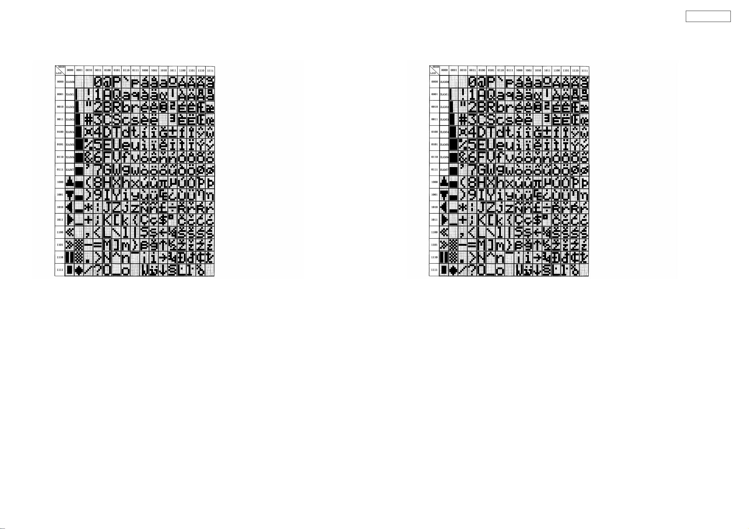
VFD segment data reception
The various segments are set by 2-byte data, as per the following font code.
(0x00/0x00 to 0x00/0x07 cannot be used.)
● Font codes for segments
VFD セグメント受信データ
各セグメントは、以下のフォントコードに従い、2 バイトデータで設定する。
(0x00/0x00 から 0x00/0x07 は使用不可。)
● セグメントのフォントコード
※ For the Reflex function operations corresponding to the above MIDI commands, refer to the Reflex manual.
※ 以上の MIDI コマンドに対する Reflex の機能動作は Reflex のマニュアルを参照。
※ 本機は ASCII 文字コード(0x20 〜 0x7E)で定義される。
※ 一部の Latin 文字(ISO-8859-1)が表示できる。
17
DN-HC4500
4. Updating procedure
4.1. preparation
(1) Connect the computer by USB cable.
4.2. procedure
※ Turn on the device’s power in the update mode.
(1) Press the BACK and SOURCE buttons simultaneously on Deck1 or Deck2.
The following appears on the VFD segment display section:
Updat e Mode
Ve r * * * *
on Deck1
PC L i n k e d
Don ‘ t Tou ch !
on Deck2
If the device is not yet connected, the following appears on the VFD segment display section:
PC D i s c o n n . .
on Deck2
The version informationis displayed.
4. バージョンアップ手順
4.1. 準備
(1) PC と機器を USB で接続する。
4.2. 手順
※ 機器をバージョンアップモードで電源を立ち上げる。
(1) Deck1 または Deck2 の BACK ボタンと SOURCE ボタンを同時に押下しながら電源を投入する。
VFD のセグメント表示部には、Deck1 側に
Updat e Mode
Ver****
バージョン情報が表示される。
Deck2 側には以下の文字が表示される。
PC L i n k e d
Don ‘ t Tou ch !
機器が未接続場合、VFD のセグメント表示部には
Deck2 側に以下の文字が表示される。
PC D i sconn . .
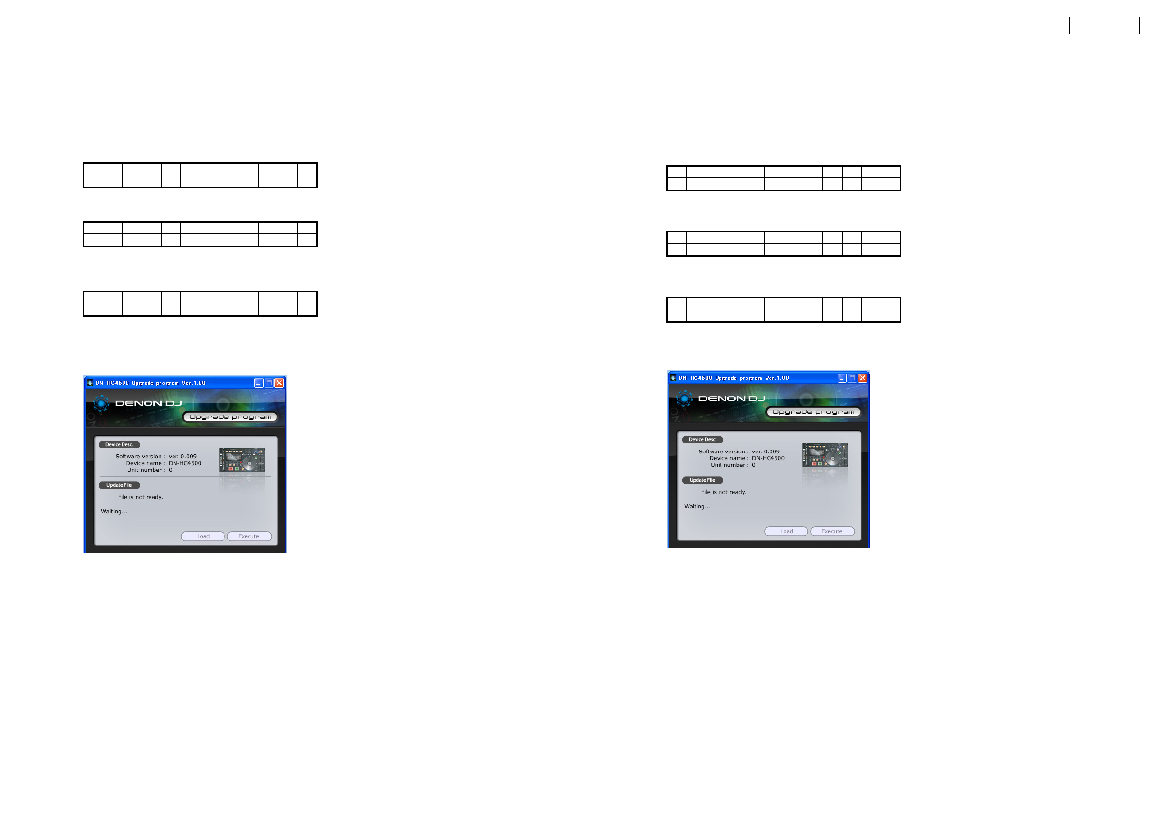
(2) Launch the DN-HC4500 update program.
The screen shown below appears on thecomputer.
Current version information
The identified device name is displayed.
(2) DN-HC4500Updateprogram を立ち上げる。
PC 上に以下の画面が表示される。
現在のバージョン情報
認識したデバイス名が表示される。
18
DN-HC4500
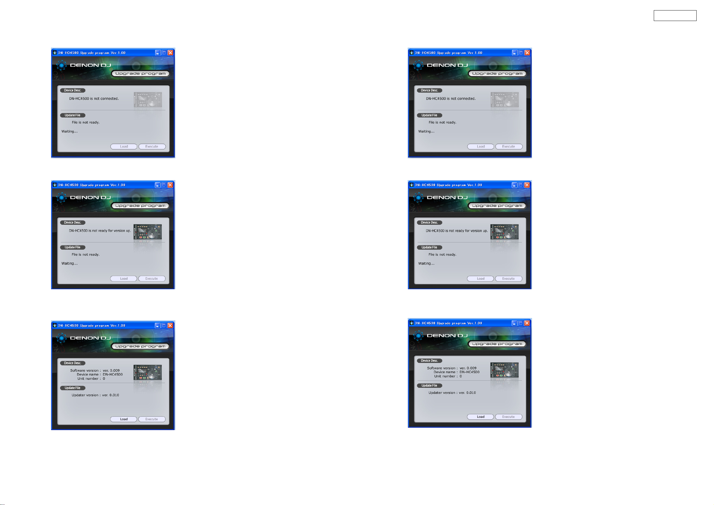
(3) If the device is not connected or not in the update mode at this time, the screen shown below is displayed.
If the update file has not been loaded, “Fileis not ready.” is displayed.
Update file not loaded
(3) このとき機器が接続されていないか、機器がバージョンアップモードでない場合は以下の図のようになる。
また、バージョンアップファイルが読み込まれていない場合はFileisnotready.が表示される。
アップデートファイルがロードされていない状態。
(4) Drag and drop the update file to the ”DENON DJ Upgrade program” screen.
The Load button can now be selected.
The Load button can be selected.
(4) アップデートファイルを DENONDJ アップグレードプログラム画面にドラッグ & ドロップする。
Load ボタンが選択できる状態になる。
Load ボタンが選択可能になる。
19
DN-HC4500
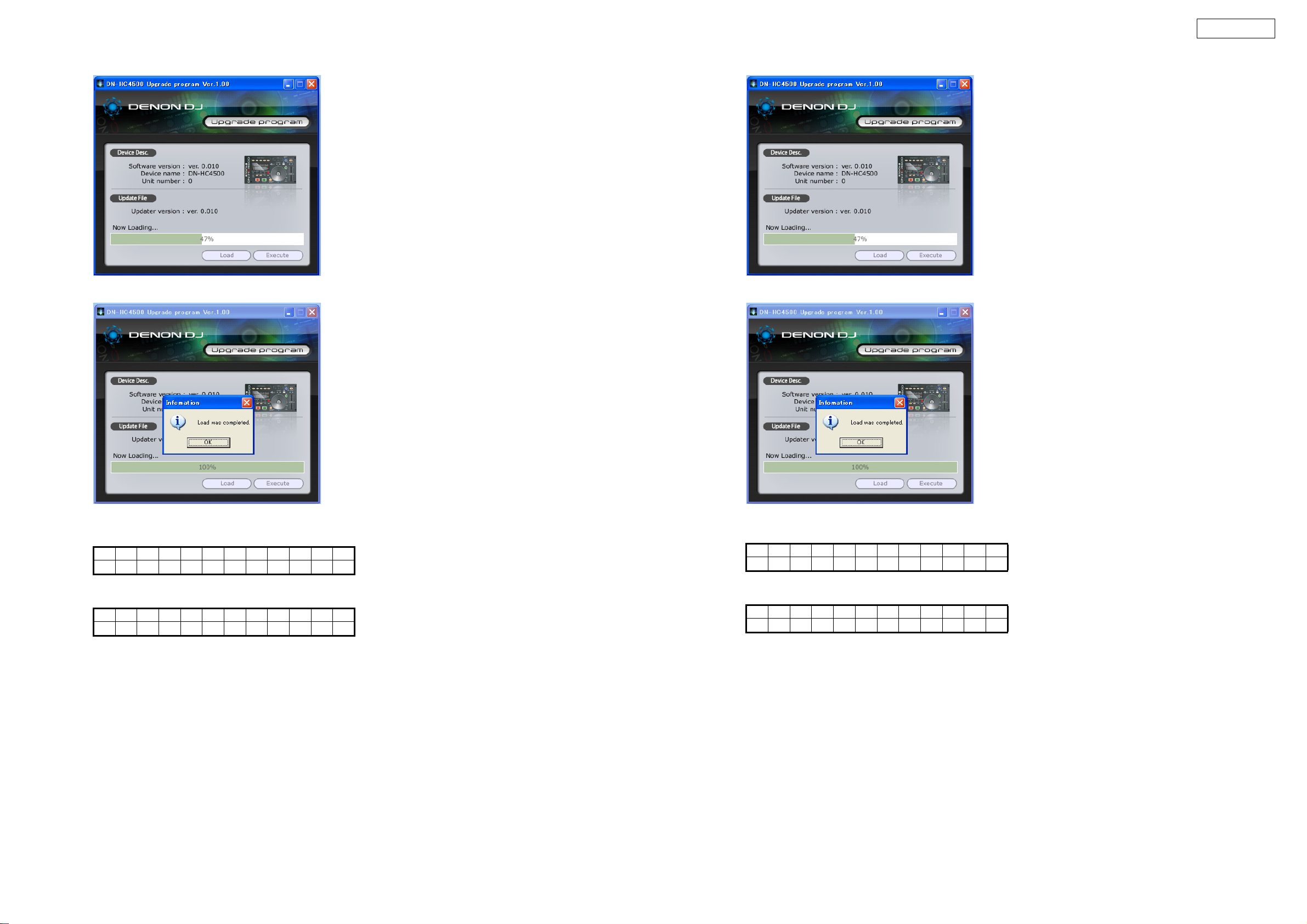
(5) Press the Load button to transfer the update file.
(5) Load ボタンを押してアップデートファイルを転送する。
(6) The following appears on the VFD segment display section:
During file transfer:on Deck1
Updat e Mode
Load i ng
Once file transfer is finished;
Updat e Mode
**** >> ****
(Left side: Old version, Right side: New version)
Once file transfer is finished, press the OK button. The Execute button is now enabled (can be pressed).
(6) VFD のセグメント表示部には、転送中 Deck1 側に以下の文字が表示される。
Updat e Mode
Load i ng
転送を完了すると以下の文字が表示される
Updat e Mode
**** >> ****
(左側:旧バージョン、右側:新バージョン)
転送完了後、OK ボタンを押すと Execute(実行)ボタンが有効表示(押せるような状態)に切り替わる。
20
 Loading...