

Page 1
AV SURROUND RECEIVER
AVR-4308
Owner’s Manual
Bedienungsanleitung
Manuel de l’Utilisateur
GraphicalUserInterface
English
Use this manual in combination with the operating
guide displayed on the GUI screen.
GUI Menu Operation (vpage 24)
GUI Menu Map (vpage 25)
Language (vpage 38)
Remote Control Unit Operations (vpage 64)
Deutsch
Verwenden Sie dieses Handbuch zusammen
mit den Bedienungsanweisungen auf dem GUIBildschirm.
GUI/OSD-Menübedienung (vSeite 24)
GUI/OSD-Menüplan (vSeite 25)
Sprache (vpage 38)
Bedienung mit der Fernbedienung (vpage 64)
Français
Utilisez ce manuel en même temps que le guide
d’utilisation affi ché sur l’écran GUI (Interface
graphique).
Fonctionnement du menu de l’interface graphique GUI
(vpage 24)
Plan du menu de l’interface graphique GUI
(vpage 25)
Langue (vpage 38)
Fonctionnement de la télécommande (vpage 64)
v
Book 1
Book 2
English Deutsch Français PRESET CODE
Italiano Español Nederlands Svenska
Page 2
CAUTION
RISK OF ELECTRIC SHOCK
DO NOT OPEN
ITALIANO ESPAÑOL NEDERLANDS SVENSKAENGLISH DEUTSCH FRANCAIS
SAFETY PRECAUTIONS
n
CAUTION:
TO REDUCE THE RISK OF ELECTRIC SHOCK, DO NOT REMOVE
COVER (OR BACK). NO USER-SERVICEABLE PARTS INSIDE.
REFER SERVICING TO QUALIFIED SERVICE PERSONNEL.
The lightning flash with arrowhead symbol, within an equilateral
triangle, is intended to alert the user to the presence of
uninsulated “dangerous voltage” within the product’s enclosure
that may be of sufficient magnitude to constitute a risk of electric
shock to persons.
The exclamation point within an equilateral triangle is intended
to alert the user to the presence of important operating
and maintenance (servicing) instructions in the literature
accompanying the appliance.
WARNING:
TO REDUCE THE RISK OF FIRE OR ELECTRIC SHOCK, DO NOT
EXPOSE THIS APPLIANCE TO RAIN OR MOISTURE.
This product may be operated in the following countries;
AT BE CZ DK FI
FR DE GR HU IE
IT NL PL PT SK
ES SE GB NO CH
• DECLARATION OF CONFORMITY
Hereby, D&M Holdings Inc., Denon Brand Company declares that this
product AVR-4308 is in compliance with the essential requirements and
other relevant provisions of Directive 1999/5/EC, in conformity with the
following standards;
EN60065, EN55013, EN55020, EN55022, EN55024, EN61000-3-2,
EN61000-3-3, EN300328, EN301489-01, EN301489-17 and EN50385.
The declaration of conformity may be consulted to our European
representative, DENON Europe.
• ÜBEREINSTIMMUNGSERKLÄRUNG
Hiermit erklärt D&M Holdings Inc., Denon Brand Company, dass sich
das Gerät AVR-4308 in Übereinstimmung mit den grundlegenden
Anforderungen und den übrigen einschlägigen Bestimmungen der
Richtlinie 1999/5/EG befindet, den folgenden Standards entspricht:
EN60065, EN55013, EN55020, EN55022, EN55024, EN61000-3-2,
EN61000-3-3, EN300328, EN301489-01, EN301489-17 und EN50385.
Wenden Sie sich bei Fragen zur Konformitätserklärung an unseren
europäischen Vertreter, DENON Europe.
R&TTE Directive 1999/5/EC
• DECLARATION DE CONFORMITE
Par la présente, D&M Holdings Inc., Denon Brand Company déclare
que l’appareil AVR-4308 est conforme aux exigences essentielles et aux
autres dispositions pertinentes de la directive 1999/5/CE, e conforme alle
seguenti normative:
EN60065, EN55013, EN55020, EN55022, EN55024, EN61000-3-2,
EN61000-3-3, EN300328, EN301489-01, EN301489-17 e EN50385.
La déclaration de conformité pourra être consultée auprès de notre
représentant en Europe, DENON Europe.
• DICHIARAZIONE DI CONFORMITÀ
Con la presente D&M Holdings Inc., Denon Brand Company dichiara
che questo AVR-4308 è con-forme ai requisiti essenziali ed alle altre
disposizioni pertinenti stabilite dalla direttiva 1999/5/CE, e conforme alle
seguenti normative:
EN60065, EN55013, EN55020, EN55022, EN55024, EN61000-3-2,
EN61000-3-3, EN300328, EN301489-01, EN301489-17 e EN50385.
La dichiarazione di conformità può essere consultata presso il nostro
rappresentante europeo, DENON Europe.
QUESTO PRODOTTO E’ CONFORME
AL D.M. 28/08/95 N. 548
• DECLARACIÓN DE CONFORMIDAD
Por la presente, D&M Holdings Inc., Denon Brand Company, declara que
este AVR-4308 cumple con los requisitos esenciales y otras exigencias
relevantes de la Directiva 1999/5/EC, esta conforme con los siguientes
estandares:
EN60065, EN55013, EN55020, EN55022, EN55024, EN61000-3-2,
EN61000-3-3, EN300328, EN301489-01, EN301489-17 y EN50385.
Puede consultar a nuestro representante europeo, DENON Europe, acerca
de la declaración de conformidad.
• EENVORMIGHEIDSVERKLARING
Hierbij verklaart D&M Holdings Inc., Denon Brand Company dat het toestel
AVR-4308 in overeenstemming is met de essentiële eisen en de andere
relevante bepalingen van richtlijn 1999/5/EG, in overeenstemming is met
de volgende normen:
EN60065, EN55013, EN55020, EN55022, EN55024, EN61000-3-2,
EN61000-3-3, EN300328, EN301489-01, EN301489-17 en EN50385.
De eenvormigheidsverklaring mag worden geconsulteerd aan onze
Europese vertegenwoordiger, DENON Europe.
• ÖVERENSSTÄMMELSESINTYG
Denna utrustning är i överensstämmelse med de väsentliga kraven och
andra relevanta bestämmelser i Direktiv 1999/5/EC, uppfyller foljande
standarder:
EN60065, EN55013, EN55020, EN55022, EN55024, EN61000-3-2,
EN61000-3-3, EN300328, EN301489-01, EN301489-17 och EN50385.
EU-konformitetsintyget kan på begäran fås från DENON Europe, vår
representant i Europe.
DENON EUROPE
Division of D&M Germany GmbH
An der Landwehr 19, Nettetal,
D-41334 Germany
CAUTION:
To completely disconnect this product from the mains, disconnect
the plug from the wall socket outlet.
The mains plug is used to completely interrupt the power supply to
the unit and must be within easy access by the user.
VORSICHT:
Um dieses Gerät vollständig von der Stromversorgung abzutrennen,
ziehen Sie bitte den Stecker aus der Wandsteckdose.
Der Netzstecker wird verwendet, um die Stromversorgung zum
Gerät völlig zu unterbrechen; er muss für den Benutzer gut und
einfach zu erreichen sein.
PRECAUTION:
Pour déconnecter complètement ce produit du courant secteur,
débranchez la prise de la prise murale.
La prise secteur est utilisée pour couper complètement
l’alimentation de l’appareil et l’utilisateur doit pouvoir y accéder
facilement.
ATTENZIONE:
Per scollegare completamente questo prodotto dalla rete di
alimentazione elettrica, scollegare la spina dalla relativa presa a muro.
La spina di rete viene utilizzata per interrompere completamente
l’alimentazione all’unità e deve essere facilmente accessibile
all’utente.
PRECAUCIÓN:
Para desconectar completamente este producto de la alimentación
eléctrica, desconecte el enchufe del enchufe de la pared.
El enchufe de la alimentación eléctrica se utiliza para interrumpir por
completo el suministro de alimentación eléctrica a la unidad y debe
de encontrarse en un lugar al que el usuario tenga fácil acceso.
WAARSCHUWING:
Om de voeding van dit product volledig te onderbreken moet de
stekker uit het stopcontact worden getrokken.
De netstekker wordt gebruikt om de stroomtoevoer naar het toestel
volledig te onderbreken en moet voor de gebruiker gemakkelijk
bereikbaar zijn.
FÖRSIKTIHETSMÅTT:
Koppla loss stickproppen från eluttaget för att helt skilja produkten
från nätet.
Stickproppen används för att helt bryta strömförsörjningen till
apparaten, och den måste vara lättillgänglig för användaren.
I
Page 3
NOTE ON USE / HINWEISE ZUM GEBRAUCH / OBSERVATIONS RELATIVES A L’UTILISATION / NOTE SULL’USO /
n
NOTAS SOBRE EL USO / ALVORENS TE GEBRUIKEN / OBSERVERA ANGÅENDE ANVÄNDNINGEN
CAUTION:
• The ventilation should not be impeded by covering the ventilation openings with items,
such as newspapers, tablecloths, curtains, etc.
• No naked flame sources, such as lighted candles, should be placed on the unit.
• Observe and follow local regulations regarding battery disposal.
• Do not expose the unit to dripping or splashing fluids.
• Do not place objects filled with liquids, such as vases, on the unit.
ACHTUNG:
• Die Belüftung sollte auf keinen Fall durch das Abdecken der Belüftungsöffnungen durch
Gegenstände wie beispielsweise Zeitungen, Tischtücher, Vorhänge o. Ä. behindert
werden.
• Auf dem Gerät sollten keinerlei direkte Feuerquellen wie beispielsweise angezündete
Kerzen aufgestellt werden.
• Bitte beachten Sie bei der Entsorgung der Batterien die örtlich geltenden
Umweltbestimmungen.
• Das Gerät sollte keiner tropfenden oder spritzenden Flüssigkeit ausgesetzt werden.
• Auf dem Gerät sollten keine mit Flüssigkeit gefüllten Behälter wie beispielsweise Vasen
aufgestellt werden.
ATTENTION:
• La ventilation ne doit pas être gênée en recouvrant les ouvertures de la ventilation avec des
objets tels que journaux, rideaux, tissus, etc.
• Aucune flamme nue, par exemple une bougie, ne doit être placée sur l’appareil.
• Veillez à respecter les lois en vigueur lorsque vous jetez les piles usagées.
• L’appareil ne doit pas être exposé à l’eau ou à l’humidité.
• Ne pas poser d’objet contenant du liquide, par exemple un vase, sur l’appareil.
ATTENZIONE:
• Le aperture di ventilazione non devono essere ostruite coprendole con oggetti, quali
giornali, tovaglie, tende e così via.
• Non posizionate sull’unità fiamme libere, come ad esempio candele accese.
• Prestate attenzione agli aspetti legati alla tutela dell’ambiente nello smaltimento delle
batterie.
• L’apparecchiatura non deve essere esposta a gocciolii o spruzzi.
• Non posizionate sull’unità alcun oggetto contenente liquidi, come ad esempio i vasi.
PRECAUCIÓN:
• La ventilación no debe quedar obstruida por haberse cubierto las aperturas con objetos
como periódicos, manteles, cortinas, etc.
• No debe colocarse sobre el aparato ninguna fuente inflamable sin protección, como velas
encendidas.
• A la hora de deshacerse de las pilas, respete la normativa para el cuidado del medio
ambiente.
• No exponer el aparato al goteo o salpicaduras cuando se utilice.
• No colocar sobre el aparato objetos llenos de líquido, como jarros.
WAARSCHUWING:
• De ventilatie mag niet worden belemmerd door de ventilatieopeningen af te dekken met
bijvoorbeeld kranten, een tafelkleed, gordijnen, enz.
• Plaats geen open vlammen, bijvoorbeeld een brandende kaars, op het apparaat.
• Houd u steeds aan de milieuvoorschriften wanneer u gebruikte batterijen wegdoet.
• Stel het apparaat niet bloot aan druppels of spatten.
• Plaats geen voorwerpen gevuld met water, bijvoorbeeld een vaas, op het apparaat.
OBSERVERA:
• Ventilationen bör inte förhindras genom att täcka för ventilationsöppningarna med föremål
såsom tidningar, bordsdukar, gardiner osv.
• Inga blottade brandkällor, såsom tända ljus, får placeras på apparaten.
• Tänk på miljöaspekterna när du bortskaffar batterier.
• Apparaten får inte utsättas för vätska.
• Placera inte föremål fyllda med vätska, t.ex. vaser, på apparaten.
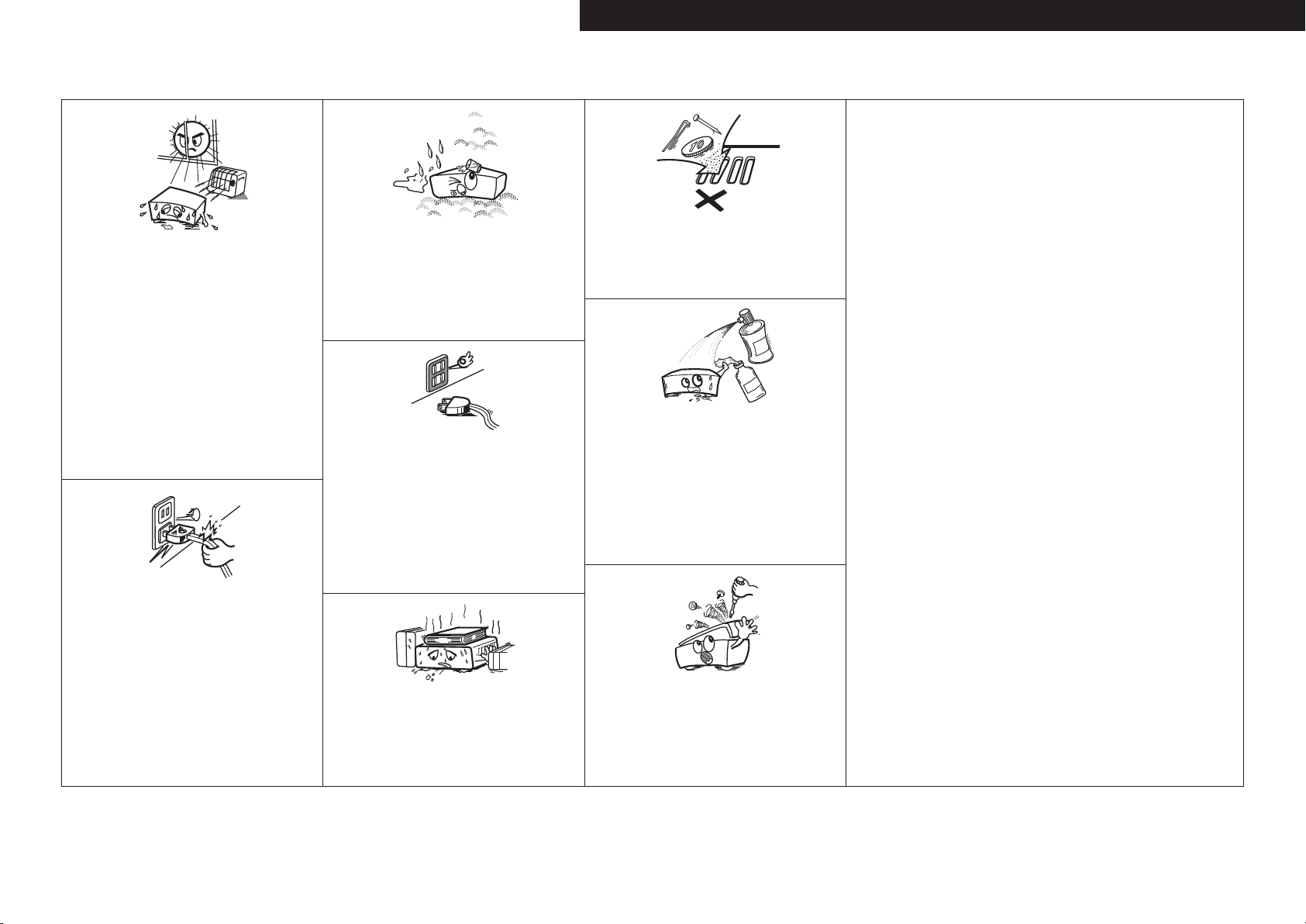
• Avoid high temperatures.
Allow for sufficient heat dispersion when installed in a rack.
• Vermeiden Sie hohe Temperaturen.
Beachten Sie, dass eine ausreichende Belüftung gewährleistet
wird, wenn das Gerät auf ein Regal gestellt wird.
• Eviter des températures élevées.
Tenir compte d’une dispersion de chaleur suffisante lors de
l’installation sur une étagère.
• Evitate di esporre l’unità a temperature elevate.
Assicuratevi che vi sia un’adeguata dispersione del calore
quando installate l’unità in un mobile per componenti audio.
• Evite altas temperaturas.
Permite la suficiente dispersión del calor cuando está
instalado en la consola.
• Vermijd hoge temperaturen.
Zorg er bij installatie in een audiorack voor, dat de door
het toestel geproduceerde warmte goed kan worden
afgevoerd.
• Undvik höga temperaturer.
Se till att det finns möjlighet till god värmeavledning vid
montering i ett rack.
• Handle the power cord carefully.
Hold the plug when unplugging the cord.
• Gehen Sie vorsichtig mit dem Netzkabel um.
Halten Sie das Kabel am Stecker, wenn Sie den Stecker
herausziehen.
• Manipuler le cordon d’alimentation avec précaution.
Tenir la prise lors du débranchement du cordon.
• Manneggiate il cavo di alimentazione con attenzione.
Tenete ferma la spina quando scollegate il cavo dalla presa.
• Maneje el cordón de energía con cuidado.
Sostenga el enchufe cuando desconecte el cordón de
energía.
• Hanteer het netsnoer voorzichtig.
Houd het snoer bij de stekker vast wanneer deze moet
worden aan- of losgekoppeld.
• Hantera nätkabeln varsamt.
Håll i kabeln när den kopplas från el-uttaget.
• Keep the unit free from moisture, water, and dust.
• Halten Sie das Gerät von Feuchtigkeit, Wasser und Staub
fern.
• Protéger l’appareil contre l’humidité, l’eau et la poussière.
• Tenete l’unità lontana dall’umidità, dall’acqua e dalla
polvere.
• Mantenga el equipo libre de humedad, agua y polvo.
• Laat geen vochtigheid, water of stof in het apparaat
binnendringen.
• Utsätt inte apparaten för fukt, vatten och damm.
• Unplug the power cord when not using the unit for long
periods of time.
• Wenn das Gerät längere Zeit nicht verwendet werden soll,
trennen Sie das Netzkabel vom Netzstecker.
• Débrancher le cordon d’alimentation lorsque l’appareil n’est
pas utilisé pendant de longues périodes.
• Scollegate il cavo di alimentazione quando prevedete di non
utilizzare l’unità per un lungo periodo di tempo.
• Desconecte el cordón de energía cuando no utilice el equipo
por mucho tiempo.
Neem altijd het netsnoer uit het stopkontakt wanneer het
•
apparaat gedurende een lange periode niet wordt gebruikt.
• Koppla loss nätkabeln om apparaten inte kommer att
användas i lång tid.
* (For apparatuses with ventilation holes)
• Do not obstruct the ventilation holes.
• Decken Sie den Lüftungsbereich nicht ab.
• Ne pas obstruer les trous d’aération.
• Non coprite i fori di ventilazione.
• No obstruya los orificios de ventilación.
• De ventilatieopeningen mogen niet worden beblokkeerd.
• Täpp inte till ventilationsöppningarna.
• Do not let foreign objects into the unit.
Lassen Sie keine fremden Gegenstände in das Gerät kommen.
•
• Ne pas laisser des objets étrangers dans l’appareil.
• Non inserite corpi estranei all’interno dell’unità.
• No deje objetos extraños dentro del equipo.
• Laat geen vreemde voorwerpen in dit apparaat vallen.
• Se till att främmande föremål inte tränger in i apparaten.
• Do not let insecticides, benzene, and thinner come in
contact with the unit.
• Lassen Sie das Gerät nicht mit Insektiziden, Benzin oder
Verdünnungsmitteln in Berührung kommen.
• Ne pas mettre en contact des insecticides, du benzène et
un diluant avec l’appareil.
• Assicuratevi che l’unità non entri in contatto con insetticidi,
benzolo o solventi.
• No permita el contacto de insecticidas, gasolina y diluyentes
con el equipo.
• Voorkom dat insecticiden, benzeen of verfverdunner met dit
toestel in contact komen.
• Se till att inte insektsmedel på spraybruk, bensen och
thinner kommer i kontakt med apparatens hölje.
• Never disassemble or modify the unit in any way.
• Versuchen Sie niemals das Gerät auseinander zu nehmen
oder zu verändern.
• Ne jamais démonter ou modifier l’appareil d’une manière ou
d’une autre.
• Non smontate né modificate l’unità in alcun modo.
• Nunca desarme o modifique el equipo de ninguna manera.
• Dit toestel mag niet gedemonteerd of aangepast worden.
• Ta inte isär apparaten och försök inte bygga om den.
ENGLISHDEUTSCHFRANCAISITALIANOESPAÑOLNEDERLANDSSVENSKA
II
Page 4
ITALIANO ESPAÑOL NEDERLANDS SVENSKAENGLISH DEUTSCH FRANCAIS
A NOTE ABOUT RECYCLING:
This product’s packaging materials are recyclable and can be reused. Please dispose of any materials
in accordance with the local recycling regulations.
When discarding the unit, comply with local rules or regulations.
Batteries should never be thrown away or incinerated but disposed of in accordance with the local
regulations concerning battery disposal.
This product and the supplied accessories, excluding the batteries, constitute the applicable product
according to the WEEE directive.
HINWEIS ZUM RECYCLING:
Das Verpackungsmaterial dieses Produktes ist zum Recyceln geeignet und kann wieder verwendet werden. Bitte
entsorgen Sie alle Materialien entsprechend der örtlichen Recycling-Vorschriften.
Beachten Sie bei der Entsorgung des Gerätes die örtlichen Vorschriften und Bestimmungen.
Die Batterien dürfen nicht in den Hausmüll geworfen oder verbrannt werden; bitte entsorgen Sie die Batterien gemäß
der örtlichen Vorschriften.
Dieses Produkt und das im Lieferumfang enthaltene Zubehör (mit Ausnahme der Batterien!) entsprechen der WEEEDirektive.
UNE REMARQUE CONCERNANT LE RECYCLAGE:
Les matériaux d’emballage de ce produit sont recyclables et peuvent être réutilisés. Veuillez disposer des matériaux
conformément aux lois sur le recyclage en vigueur.
Lorsque vous mettez cet appareil au rebut, respectez les lois ou réglementations en vigueur.
Les piles ne doivent jamais être jetées ou incinérées, mais mises au rebut conformément aux lois en vigueur sur la
mise au rebut des piles.
Ce produit et les accessoires inclus, à l’exception des piles, sont des produits conformes à la directive DEEE.
NOTA RELATIVA AL RICICLAGGIO:
I materiali di imballaggio di questo prodotto sono riutilizzabili e riciclabili. Smaltire i materiali conformemente alle
normative locali sul riciclaggio.
Per lo smaltimento dell’unità, osservare le normative o le leggi locali in vigore.
Non gettare le batterie, né incenerirle, ma smaltirle conformemente alla normativa locale sui rifiuti chimici.
Questo prodotto e gli accessori inclusi nell’imballaggio sono applicabili alla direttiva RAEE, ad eccezione delle batterie.
ACERCA DEL RECICLAJE:
Los materiales de embalaje de este producto son reciclables y se pueden volver a utilizar. Disponga de estos materiales
siguiendo los reglamentos de reciclaje de su localidad.
Cuando se deshaga de la unidad, cumpla con las reglas o reglamentos locales.
Las pilas nunca deberán tirarse ni incinerarse. Deberá disponer de ellas siguiendo los reglamentos de su localidad
relacionados con los desperdicios químicos.
Este producto junto con los accesorios empaquetados es el producto aplicable a la directiva RAEE excepto pilas.
EEN AANTEKENING MET BETREKKING TOT DE RECYCLING:
Het inpakmateriaal van dit product is recycleerbaar en kan opnieuw gebruikt worden. Er wordt verzocht om zich van
elk afvalmateriaal te ontdoen volgens de plaatselijke voorschriften.
Volg voor het wegdoen van de speler de voorschriften voor de verwijdering van wit- en bruingoed op.
Batterijen mogen nooit worden weggegooid of verbrand, maar moeten volgens de plaatselijke voorschriften
betreffende chemisch afval worden verwijderd.
Op dit product en de meegeleverde accessoires, m.u.v. de batterijen is de richtlijn voor afgedankte elektrische en
elektronische apparaten (WEEE) van toepassing.
OBSERVERA ANGÅENDE ÅTERVINNING:
Produktens emballage är återvinningsbart och kan återanvändas. Kassera det enligt lokala återvinningsbestämmelser.
När du kasserar enheten ska du göra det i överensstämmelse med lokala regler och bestämmelser.
Batterier får absolut inte kastas i soporna eller brännas. Kassera dem enligt lokala bestämmelser för kemiskt avfall.
Denna apparat och de tillbehör som levereras med den uppfyller gällande WEEE-direktiv, med undantag av
batterierna.
1. IMPORTANT NOTICE: DO NOT MODIFY THIS PRODUCT
This product, when installed as indicated in the instructions contained in this manual, meets R&TTE directive
requirements. Modification of the product could result in hazardous Radio and EMC radiation.
2. CAUTION
• Separation distance of at least 20 cm must be maintained between the antenna of this product and all persons.
• This product and its antenna must not be co-located or operating in conjunction with any other antenna or
transmitter.
1. WICHTIGER HINWEIS: NEHMEN SIE KEINE VERÄNDERUNGEN AN DIESEM PRODUKT VOR
Wenn dieses Produkt entsprechend dieser Bedienungsanleitung aufgebaut wird, entspricht es den Anforderungen
der R&TTE-Richtlinie. Veränderungen am Produkt können zu gefährlicher Funk- und EMV-Strahlung führen.
2. VORSICHT
• Zwischen der Antenne dieses Produkts und Personen muss ein Schutzabstand von 20 cm eingehalten werden.
• Dieses Produkt und seine Antenne dürfen nicht neben anderen Antennen oder Sendern aufgestellt oder
zusammen mit ihnen verwendet werden.
1. MISE EN GARDE IMPORTANTE : NE JAMAIS MODIFIER CE PRODUIT
Si toutes les consignes indiquées dans ce mode ont été respectées pendant son installation, ce produit est
conforme aux directives R&TTE. Toute modification du produit risquerait alors de générer des radiations radio et
EMC dangereuses.
2. ATTENTION
• L’antenne de l’appareil devra être située à une distance de 20 cm au moins des personnes.
• Ce produit ainsi que son antenne ne devront en aucun cas être utilisés à proximité d’une autre antenne ou
transmetteur.
1. AVVERTENZA IMPORTANTE: NON MODIFICARE QUESTO PRODOTTO
Se installato come indicato nelle istruzioni del presente manuale, questo prodotto soddisfa i requisiti della direttiva
R&TTE. Eventuali modifiche apportate al prodotto potrebbero causare pericolose radiazioni radio ed EMC.
2. ATTENZIONE
• È necessario mantenere una distanza minima di 20 cm tra l’antenna di questo prodotto e le persone.
• Questo prodotto e la relativa antenna non devono essere posizionati in prossimità di altre antenne o trasmettitori
e non devono essere utilizzati congiuntamente a questi ultimi.
1. NOTA IMPORTANTE: NO MODIFIQUE ESTE PRODUCTO
Este producto, si es instalado de acuerdo con las instrucciones contenidas en este manual, cumple los requisitos
de la directiva R&TTE. La modificación del producto puede producir radiación de Radio y EMC peligrosa.
2. PRECAUCIÓN
• Se debe mantener una separación de al menos 20 cm entre la antena del producto y las personas.
• Este producto y su antena no debe instalarse ni utilizarse conjuntamente con otra antena o transmisor.
1. BELANGRIJKE MEDEDELING: BRENG AAN DIT PRODUCT GEEN AANPASSINGEN AAN
Dit product, indien geïnstalleerd volgens de aanwijzingen in deze gebruiksaanwijzing, voldoet aan de vereisten van
de R&TTE-richtlijn. Aanpassing van dit product kan gevaarlijke radio- en EMC-straling tot gevolg hebben.
2. LET OP
• Houd tussen antenne en personen altijd een afstand van tenminste 20 cm aan.
• Dit product en zijn antenne mogen niet in de buurt van een andere antenne of zender worden geplaatst of in
combinatie daarmee worden gebruikt.
1. VIKTIGT: APPARATEN FÅR INTE MODIFIERAS
Under förutsättning att apparaten installeras enligt anvisningarna i denna bruksanvisning, uppfyller denna kraven i
R&TTE-direktivet. Ev. modifiering av apparaten kan resultera i farlig radio- och elektromagnetisk strålning.
2. FÖRSIKTIGT
• Se till att det finns ett avstånd på minst 20 cm mellan apparatens antenn och personer i omgivningen.
• Apparaten och dess antenn får inte placeras eller användas i närheten av andra antenner eller sändare.
III
Page 5

ENGLISH
Contents
Getting Started
Accessories ······················································································3
Cautions on Handling ····································································· 3
Cautions on Installation ·································································3
About the Remote Control Unit ····················································4
Inserting the Batteries ····································································4
Operating Range of the Remote Control Unit ································ 4
Part Names and Functions ·····························································5
Front Panel ·····················································································5
Display ···························································································5
Rear Panel ······················································································6
Remote Control Unit ······································································ 7
Connections
Preparations ····················································································8
Cables Used for Connections ························································8
Video Conversion Function ····························································· 9
Speaker Connections ··································································· 10
Speaker Installation ······································································ 10
Speaker Connections ······························································10, 11
Connecting Equipment with HDMI connectors ·························12
Connecting the Monitor ······························································· 13
Connecting the Playback Components ······································13
DVD Player ··················································································· 13
Record Player ···············································································14
CD Player ····················································································· 14
iPod® ···························································································· 14
TV/CABLE Tuner ··········································································· 15
Satellite Receiver ········································································· 15
Connecting the Recording Components ···································· 16
Digital Video Recorder ·································································· 16
Video Cassette Recorder ····························································· 16
CD Recorder / MD Recorder / Tape Deck ····································· 17
Connections to Other Devices ····················································· 17
Components Equipped with a DENON LINK connector ·············· 17
Video Camera / Game Console ···················································· 18
Component with Multi-channel Output connectors ····················· 18
External Power Amplifier ······························································ 18
USB Port ······················································································ 19
Antenna terminals ·······································································20
Network Audio ············································································· 21
Multi Zone ····················································································22
External Controller ·······································································22
Connecting the Power Cord·························································23
Once Connections are Completed ··············································23
GUI Menu Operations
Example of the Display of the GUI Mark at a Title·····················24
Example of Display of Default Values ········································· 24
Examples of GUI Screen Displays ···············································24
Example: Browse Menu (Top Menu)············································ 24
Example: Menus with Illustrations (Auto Setup) ·························· 24
Cursor Position Display ································································ 24
Operations ····················································································· 24
GUI Menu Map ·············································································· 25
Auto Setup
Preparations ··················································································26
Auto Setup ····················································································27
a Auto Setup ·············································································· 27
Error Messages ·······································································28
s
Option ····················································································· 28
d
Parameter Check ·····································································28
Manual Setup
Speaker Setup···············································································29
a
Speaker Configuration ·····························································29
s
Subwoofer Mode ····································································29
d
Distance ··················································································29
f
Channel Level··········································································30
g
Crossover Frequency ······························································30
h
Surround Speaker ···································································30
HDMI Setup ···················································································31
a
i/p Scaler ·················································································31
s
Resolution ···············································································31
d
Progressive Mode ···································································31
f
Aspect ·····················································································31
g
Color Space ·············································································31
h
RGB Range ·············································································31
j
Auto Lip Sync ··········································································31
k
Audio ·······················································································31
l
Monitor Out ············································································31
Audio Setup ··················································································32
a
EXT. IN Setup ··········································································
s
2ch Direct/Stereo ····································································
d
Downmix Option ·····································································
f
Auto Surround Mode ······························································
g
Manual EQ ·············································································· 33
Network Setup ··············································································33
a
Network Setup ··································································33, 34
s
Other ·······················································································35
d
Network Information ·······························································35
32
32
32
32
Zone Setup ····················································································35
a
ZONE2 ····················································································35
s
ZONE3 ····················································································35
Option Setup ················································································· 36
a
Amp Assign ·············································································
s
Volume Control ·······································································
d
Source Delete ·········································································
f
GUI ··························································································
g
Quick Select Name ·································································
h
Trigger Out 1 ··········································································· 37
j
Trigger Out 2 ··········································································· 37
k
Digital Out ···············································································37
l
Remote ID ···············································································37
A0
2Way Remote ·········································································37
A1
Dimmer ···················································································37
A2
Setup Lock ··············································································37
A3
Maintenance Mode ·································································37
A4
Firmware Update ···································································· 38
Language ·······················································································38
Source Select
Input Source Selection ··························································· 38, 39
Settings Related to Playing Input Sources ································· 39
a
Play ·························································································
s
Auto Preset ·············································································
d
Preset Skip ··············································································
f
Preset Name ···········································································
g
Input Mode ·············································································40
h
Rename ···················································································40
j
Other ·······················································································40
k
Playback Mode (iPod) ······························································40
l
Assign ····················································································· 41
A0
Playback Mode ········································································41
A1
Still Picture ··············································································42
A2
Auto Tune ················································································ 42
A3
Tuning Aid ···············································································42
A4
DRC Value ··············································································· 42
36
36
36
36
36
39
39
39
39
Page 6

ENGLISH
Surround Modes
Standard Playback ········································································ 43
Surround Playback of 2-channel Sources ·····································43
Playing Multi-channel Sources (Dolby Digital, DTS, etc.) ·············43
DSP Simulation Playback·····························································43
Stereo Playback ············································································44
Direct Playback ·············································································44
Playback in the PURE DIRECT Mode ··········································· 44
Parameter
Audio······························································································44
a
Surround Parameters ······················································44 ~ 46
s
Tone ························································································46
d
Room EQ ················································································46
f
RESTORER ··············································································46
g
Night Mode ·············································································47
h
Audio Delay ·············································································47
Picture Adjust ················································································ 47
a
Contrast ··················································································47
s
Brightness ···············································································47
d
Chroma Level ··········································································47
f
Hue ·························································································47
Information
Status ····························································································47
a
MAIN ZONE ············································································47
s
ZONE2/3/4 ··············································································47
Audio Input Signal ········································································ 48
HDMI Information ·········································································48
a
Signal Information ···································································48
s
Monitor1 ·················································································48
d
Monitor2 ·················································································48
Auto Surround ··············································································
Quick Select ··················································································
Preset Station ···············································································
Playback
Preparations ··················································································49
Turning the Power On ··································································49
Operations During Playback ·························································49
Playing Video and Audio Equipment ···········································49
Basic Operation ············································································ 49
48
48
48
Listening to FM/AM Broadcasts ·················································50
Basic Operation ············································································ 50
Presetting Radio Stations (Preset Memory) ································· 50
Listening to Preset Stations ·························································51
RDS (Radio Data System) ····························································51
RDS Search ··················································································51
PTY Search ··················································································· 52
TP Search ·····················································································52
RT (Radio Text) ··············································································53
Listening to DAB broadcasts ······················································· 53
Basic Operation ············································································ 54
Station Order Selection ································································54
Check the DAB Reception Information ········································55
DAB Initialize ················································································55
iPod® Playback ············································································· 55
Basic Operation ············································································ 55
Listening to Music ·······································································56
Viewing Still Pictures or Videos on the iPod ·································56
Playing Network Audio or USB Memory Devices ······················57
Basic Operation ············································································ 58
Listening to Internet Radio ··························································· 59
Presetting Internet Radio Stations ··············································· 59
Registering Internet Radio Stations as Your Favorites ··················59
Playing Files Stored on a Computer ·············································60
Playing Files Stored on USB Memory Devices ······················ 60, 61
Operating the AVR-4308 Using a Browser (Web control) ············61
Other Operations and Functions
Other Operations ··········································································61
Playing Super Audio CD ······························································· 61
Recording on an External Device (REC OUT mode) ·····················62
Convenient Functions ··································································63
Channel Level ···············································································63
Fader Function ·············································································63
Quick Select Function ··································································63
Personal Memory Plus Function ·················································· 63
Last Function Memory ·································································63
Backup Memory ··········································································· 63
Resetting the Microprocessor ······················································63
Remote Control Unit Operations
Main Remote Control Unit···························································64
Operating DENON Audio Components ········································ 64
Presetting ····················································································· 64
Operating Preset Components ············································64 ~ 66
Setting the Remote ID ································································· 67
Learning Function ·········································································67
System Call Function ···································································· 68
Punch Through Function ·······························································68
Setting the Time the Backlight Stays Lit ······································· 69
Adjusting the Backlight’s Brightness ············································69
Resetting the Main Remote Control Unit ·····································69
Sub Remote Control Unit Operations ··································70, 71
Switching Zones ···········································································72
Setting the Zone for Which the Sub Remote Control Unit is Used
(ZONE SELECT LOCK Mode) ······················································· 72
Setting the Remote ID ································································· 72
Resetting the Settings ··································································72
Amp Assign / Multi-Zone Connections and Operations
Multi-Zone Settings with the Amp Assign Function ·········73 ~ 76
Multi-Zone Settings and Operations with Zone Pre-out Output ···76
Multi-Zone Operations ·································································77
Turning the Power On and Off······················································77
Selecting the Input Source ··························································· 77
Adjusting the Volume ···································································77
Turning off the Sound Temporarily ················································77
Other Information ································································ 78 ~ 89
Troubleshooting ···································································90 ~ 93
Specifications ········································································· 93, 94
List of preset codes ··········································· End of this manual
Page 7
e r y
i
Q2Q1
o
Q0
Getting Started
Thank you for purchasing this DENON product. To ensure proper
operation, please read these owner’s manual carefully before using
the product.
After reading them, be sure to keep them for future reference.
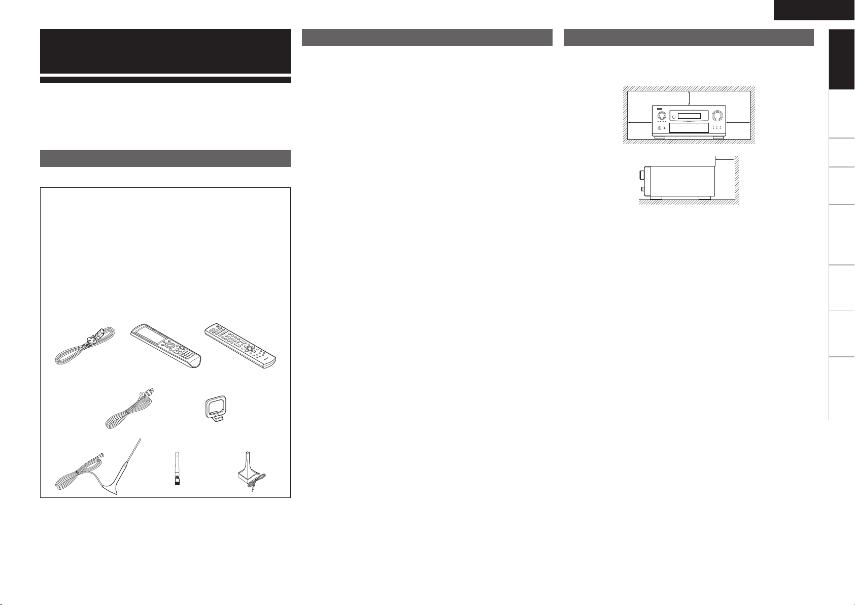
Accessories
Check that the following parts are supplied with the product.
q Owner’s manual ...................................................................... 1
w Service station list ...................................................................1
e Power cord (Cord length: Approx. 1.5 m) ................................. 1
r Main remote control (RC-1068) ............................................... 1
t LR6/AA batteries (for RC-1068) ................................................ 2
y Sub remote control (RC-1070) ................................................. 1
u R03/AAA batteries (for RC-1070) .............................................2
i FM indoor antenna ..................................................................1
o AM loop antenna ..................................................................... 1
Q0 DAB indoor antenna ................................................................1
Q1 Rod antenna for wireless LAN connection .............................. 1
Q2 Setup microphone (Cord length: Approx. 7.6 m) ...................... 1
Cautions on Handling Cautions on Installation
• Before turning the power switch on
Check once again that all connections are correct and that there are
no problems with the connection cables.
• Power is supplied to some of the circuitry even when the unit is
set to the standby mode. When traveling or leaving home for long
periods of time, be sure to unplug the power cord from the power
outlet.
• About condensation
If there is a major difference in temperature between the inside of
the unit and the surroundings, condensation (dew) may form on
the operating parts inside the unit, causing the unit not to operate
properly.
If this happens, let the unit sit for an hour or two with the power
turned off and wait until there is little difference in temperature
before using the unit.
• Cautions on using mobile phones
Using a mobile phone near this unit may result in noise. If so, move
the mobile phone away from this unit when it is in use.
• Moving the unit
Turn off the power and unplug the power cord from the power
outlet.
Next, disconnect the connection cables to other system units before
moving the unit.
• Note that the illustrations in these instructions may differ from the
actual unit for explanation purposes.
Note:
For proper heat dispersal, do not install this unit in a confined
space, such as a bookcase or similar enclosure.
b Note
b
ENGLISH
Getting Started
Connections Setup Playback Remote Control Multi-Zone Information Troubleshooting
b
b
Wall
Page 8
ENGLISH
Getting Started
About the Remote Control Unit
In addition to the AVR-4308, the included main remote control unit
(RC-1068) can also be used to operate the equipment listed below.
q DENON system components
w Non-DENON system components
Connections Setup Playback Remote Control Multi-Zone Information Troubleshooting
• By setting the preset memory (vpage 64 ~ 66)
• By using the learn function (vpage 67)
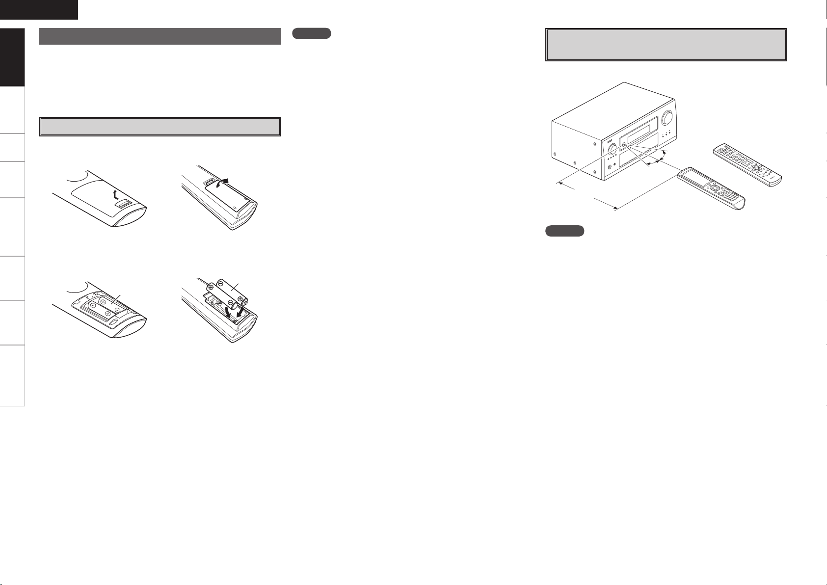
Inserting the Batteries
q Lift the clasp and remove the rear lid.
(RC-1068) (RC-1070)
w Load the two batteries properly as indicated by the marks in the
battery compartment.
(RC-1068) (RC-1070)
LR6/AA
R03/AAA
NOTE
• Replace the batteries with new ones if the set does not operate even
when the remote control unit is operated close to the unit.
• The supplied batteries are only for verifying operation.
• When inserting the batteries, be sure to do so in the proper direction,
following the “q” and “w” marks in the battery compartment.
• To prevent damage or leakage of battery fluid:
• Do not use a new battery together with an old one.
• Do not use two different types of batteries.
• Do not attempt to charge dry batteries.
• Do not short-circuit, disassemble, heat or dispose of batteries in
flames.
• If the battery fluid should leak, carefully wipe the fluid off the inside
of the battery compartment and insert new batteries.
• Remove the batteries from the remote control unit if it will not be in
use for long periods.
• When replacing the batteries, have the new batteries ready and
insert them as quickly as possible.
Operating Range of the Remote Control
Unit
Point the remote control unit at the remote sensor when operating it.
(RC-1070)
30°
30°
or
Approx. 7 m
(RC-1068)
NOTE
The set may function improperly or the remote control unit may not
operate if the remote control sensor is exposed to direct sunlight,
strong artificial light from an inverter type fluorescent lamp or infrared
light.
e Put the rear cover back on.
Page 9
w e
to i u y
q r
Q3Q2Q1Q0
t
uQ3Q7Q8 iQ0
oQ5 Q1
Q2Q4Q6 y
wq e r
Part Names and Functions
W2 W3
W4W7E2
W5W6
E3 E0E1 W8W9
Q4 Q5 Q6 Q7 Q8 W1W0Q9
For buttons not explained here, see the page indicated in parentheses ( ).
W8 INPUT MODE button ·································· (40)
W9 RESTORER button ······································(46)
E0 DIRECT/STEREO button·····························(44)
ENGLISH
E1 PURE DIRECT button ·································· (44)
E2 DSP SIMULATION button ·························· (43)
E3 STANDARD button ·····································(43)
Getting Started
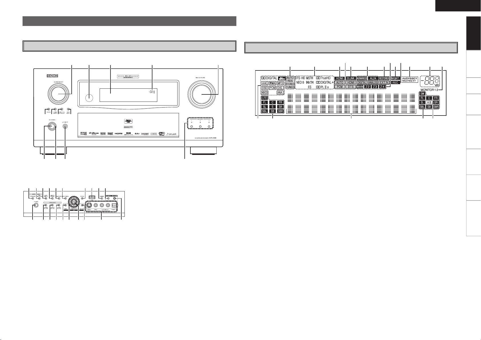
Front Panel
GWith the door openH
q Power operation button
(ON/STANDBY) ···········································(49)
w Power indicator ···········································(49)
e Power switch (hON jOFF) ·····················(49)
r QUICK SELECT buttons / indicators ·········(63)
t MASTER VOLUME control knob ·········· (49, 77)
y Master volume indicator
u Display
i Remote control sensor ································· (4)
o SOURCE SELECT knob······························· (38)
Display
q Input signal indicators
w Input signal channel indicators
These light when digital signals are input.
e Information display
The input source name, surround mode, setting
values and other information are displayed here.
r Output signal channel indicators
Q0 SOURCE button ·········································· (38)
Q1 TUNING PRESET button ···························· (51)
Q2 ZONE 2/3/4 / REC SELECT button ······(62, 77)
Q3 VIDEO SELECT button ·······························(40)
Q4 Headphones jack (PHONES) ······················ (49)
Q5 ZONE2 ON/OFF button ······························ (77)
Q6 ZONE3 ON/OFF button ······························ (77)
Q7 ZONE4 ON/OFF button ······························ (77)
Q8 MENU button ··············································(24)
Q9 Cursor buttons (uio p) ·························· (24)
W0 CH SEL / ENTER button ······················· (24, 63)
W1 RETURN button ·········································· (24)
W2 V.AUX INPUT connectors ··························· (18)
W3 SETUP MIC jack ·········································· (26)
W4 ROOM EQ button ········································ (46)
W5 DIMMER button ·········································· (37)
W6 USB port ······················································ (19)
W7 STATUS button ··········································· (48)
t Surround speaker indicators
These light according to the settings of the
surround A and B speakers.
y Monitor output indicators
These light according to the HDMI monitor
output setting. When set to “Auto (Dual)”, the
indicators light according to the connection
status.
u Master volume indicator
i AUDYSSEY MULTEQ XT indicator
This lights when the room equalizer is selected.
o Recording output source indicator
This lights when the REC OUT mode is
selected.
Q0 NIGHT indicator
This lights when the night mode is selected.
Q1 Multi zone indicators
These light when the power for the respective
zone is turned on.
Q2 RESTORER indicator
This lights when the RESTORER mode is
selected.
Q3 ADVANCED AL24 indicator
This lights when Advanced AL24 Processing is
activated (vpage 80).
Q4 D.LINK indicator
This lights when playing using DENON LINK
connections.
Q5 Input mode indicators
Q6 HDMI indicator
This lights when playing using HDMI
connections.
Q7 Decoder indicators
These light when the respective decoders are
operating.
Q8 Tuner reception mode indicators
These light according to the reception conditions
when the input source is set to “TUNER” or
“DAB”.
• AUTO
These light when in the auto tuning mode.
• RDS
These light when receiving RDS broadcasts.
• STEREO
In the FM mode, these light when receiving
analog stereo broadcasts.
• TUNED
Lights when the broadcast is properly tuned in.
Connections Setup Playback Remote Control Multi-Zone Information Troubleshooting
Page 10
ENGLISH
Q9
W0W1Q9Q9 Q9
te
i
Q0Q1Q2Q3
Q6
oQ4Q5
q
y urw
W1
Q9W0Q8
Q7
Q8
Getting Started
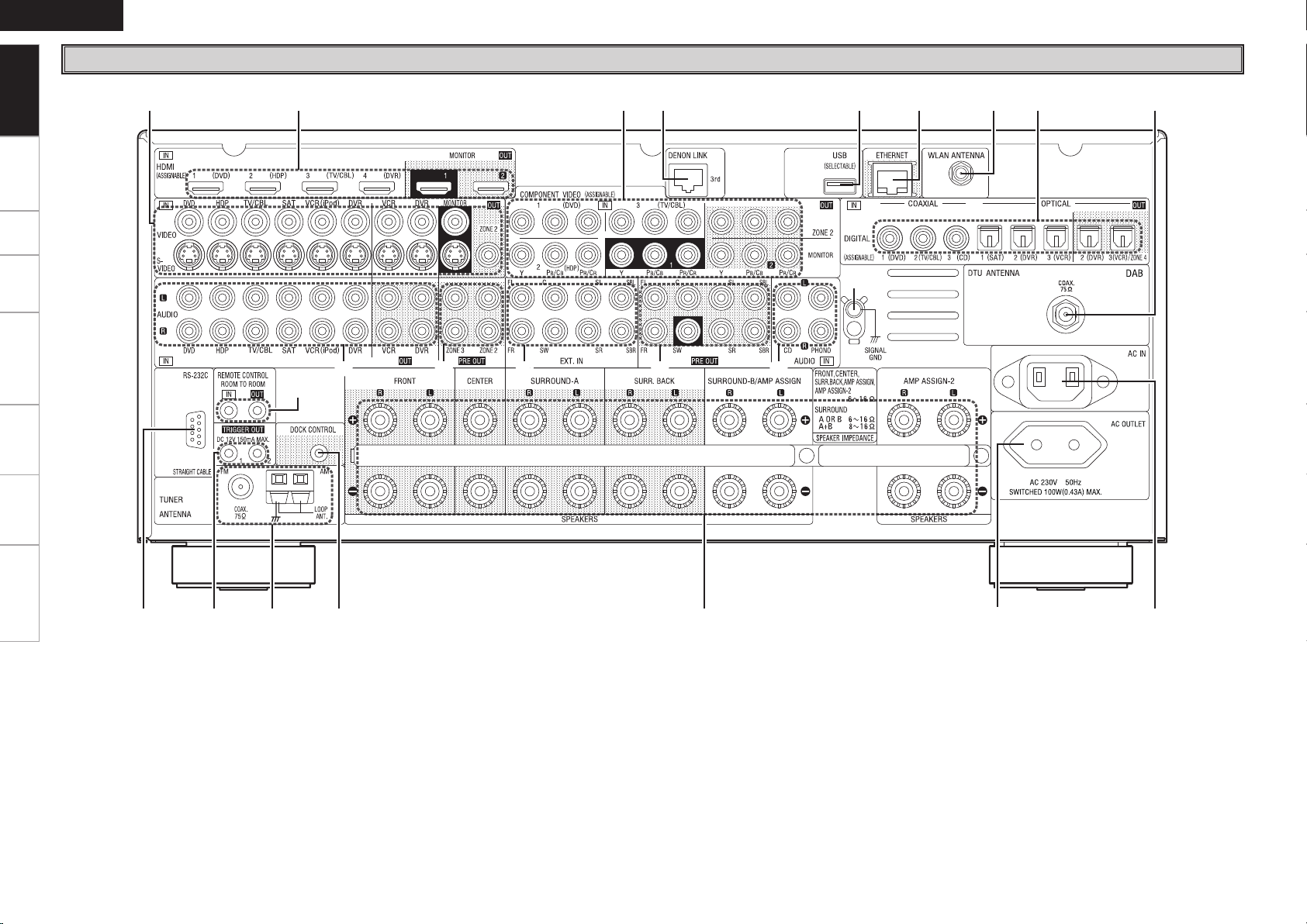
Rear Panel
Connections Setup Playback Remote Control Multi-Zone Information Troubleshooting
q RS-232C connector ····································· (22)
w TRIGGER OUT jacks ···································(22)
e FM/AM antenna terminals
(TUNER ANTENNA) ····································(20)
r DOCK CONTROL jack ································· (14)
t Speaker terminals (SPEAKERS) ················ (10)
y AC OUTLET ·················································(23)
u AC inlet (AC IN) ···········································(23)
i DAB antenna terminal
(DTU ANTENNA) ········································· (20)
o Digital audio connectors
(OPTICAL / COAXIAL) ·························· (13, 15)
Q0 WLAN ANTENNA terminal ························· (21)
Q1 ETHERNET connector ································· (21)
Q2 USB port ······················································ (19)
Q3 DENON LINK connector ····························· (17)
Q4 COMPONENT VIDEO connectors ·············· (13)
Q5 HDMI connectors ········································ (12)
Q6 VIDEO / S-VIDEO connectors ···················· (13)
Q7 REMOTE CONTROL jacks···························(22)
Q8 Analog audio connectors (AUDIO) ············ (13)
Q9 PRE OUT connectors ···························· (18, 22)
W0 EXT. IN connectors ····································· (18)
W1 SIGNAL GND terminal ······························· (14)
Page 11
q
i
w
e
r
t
y
u
o
Q1
Q3
Q4
Q2
Q0
Q5
Q6
Q7
Q9
W0
W2
W5
W7
W6
W4
W3
W1
Q8
q
r
t
y
i
o
Q0
u
e
w
Q4
Q7
Q8
Q9
W0
Q6
Q5
Q2
Q3
Q1
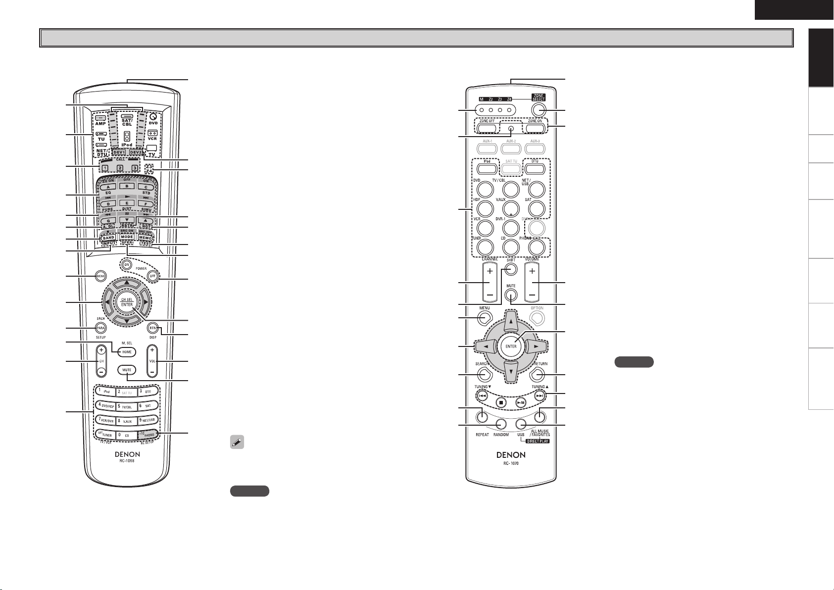
Remote Control Unit
n Main remote control unit (RC-1068) n Sub remote control unit (RC-1070)
t System buttons ···································· (65, 66)
y Audio delay button (A. DL) ························(47)
u Tuner system buttons ································(50)
i Input mode button (INPUT) ·······················(40)
o MENU button ··············································(24)
Q0 Cursor buttons (uio p) ························· (24)
Q1 Parameter / Search button
(PARA / SRCH) ································ (44, 51, 56)
q Signal transmission indicator ···················(64)
w Mode select buttons ··································(64)
e Quick select / System call buttons ·····(63, 68)
r Surround mode buttons ······················(43, 44)
Q2 Monitor select (M. SEL) /
HOME button ········································ (31, 64)
Q3 Channel buttons (CH) ·································(50)
Q4 Input source select /
Number buttons ··································· (38, 50)
Q5 Remote control signal transmitter ··············(4)
Q6 Device select indicators (DEV1 / DEV2) ···(64)
Q7 ZONE3 / ZONE4 select indicators
(Z3 / Z4) ······················································· (77)
Q8 RESTORER button (RSTR) ·························· (46)
Q9 Night button (NGT) ···································· (47)
W0 Test tone button (TEST) ····························· (30)
W1 Surround speaker select button (SPKR) ··· (30)
W2 POWER buttons ·········································· (49)
W3 Channel select (CH SEL) /
ENTER button ······································· (24, 63)
W4 Return button (RTN) ··································· (24)
W5 Master volume control buttons
(VOL) ······················································ (49, 77)
W6 Muting button (MUTE) ························· (49, 77)
W7 Main remote control unit setup button
(RC SETUP) ·················································(64)
The time for which the backlight stays on can
be changed (vpage 69 “Setting the Time the
Backlight Stays Lit”).
NOTE
The SAT TU, ZONE2 mode QUICK SELECT (1 ~ 3), A.
DL, RSTR, NGT, INPUT, SPKR, TEST and surround
mode buttons cannot be used.
ENGLISH
q ZONE indicators·········································· (72)
w Advanced setup button ······························(72)
e Input source select buttons ·······················(38)
r CHANNEL buttons ······································(50)
t SHIFT button ···············································(50)
y MENU button ··············································(24)
u Cursor buttons (uio p) ························· (24)
i SEARCH button ····································(51, 56)
o REPEAT button ············································ (56)
Q0 RANDOM button ········································(56)
Q1 Remote control signal transmitter ··············(4)
Q2 ZONE SELECT button ································· (72)
Q3 Zone power on/off buttons
(ZONE ON / ZONE OFF) ····························· (77)
Q4 Master volume control buttons
(VOLUME) ············································ (49, 77)
Q5 Muting button (MUTE) ························· (49, 77)
Q6 ENTER button ············································· (24)
Q7 RETURN button ·········································· (24)
Q8 System buttons ······························ (50, 70, 71)
Q9 ALL MUSIC/FAVORITES
(DIRECT PLAY) button ······························· (70)
W0 USB (DIRECT PLAY) button························ (70)
NOTE
The AUX-1, AUX-2, AUX-3, SAT TU, DVR-2 and
OPTION buttons cannot be used.
Getting Started
Connections Setup Playback Remote Control Multi-Zone Information Troubleshooting
Page 12
ENGLISH
R
L
R
L
Getting Started Setup Playback Remote Control Multi-Zone Information Troubleshooting
Preparations
Connections
Connections
Connections for all compatible audio and video signal formats are
described in these operating instructions. Please select the types
of connections suited for the equipment you are connecting.
With some types of connections, certain settings must be made
on the AVR-4308. For details, refer to the instructions for the
respective connection items below.
NOTE
• Do not plug in the power cord until all connections have been
completed.
• When making connections, also refer to the operating instructions of
the other components.
• Be sure to connect the left and right channels properly (left with left,
right with right).
• Do not bundle power cords together with connection cables. Doing
so can result in humming or noise.
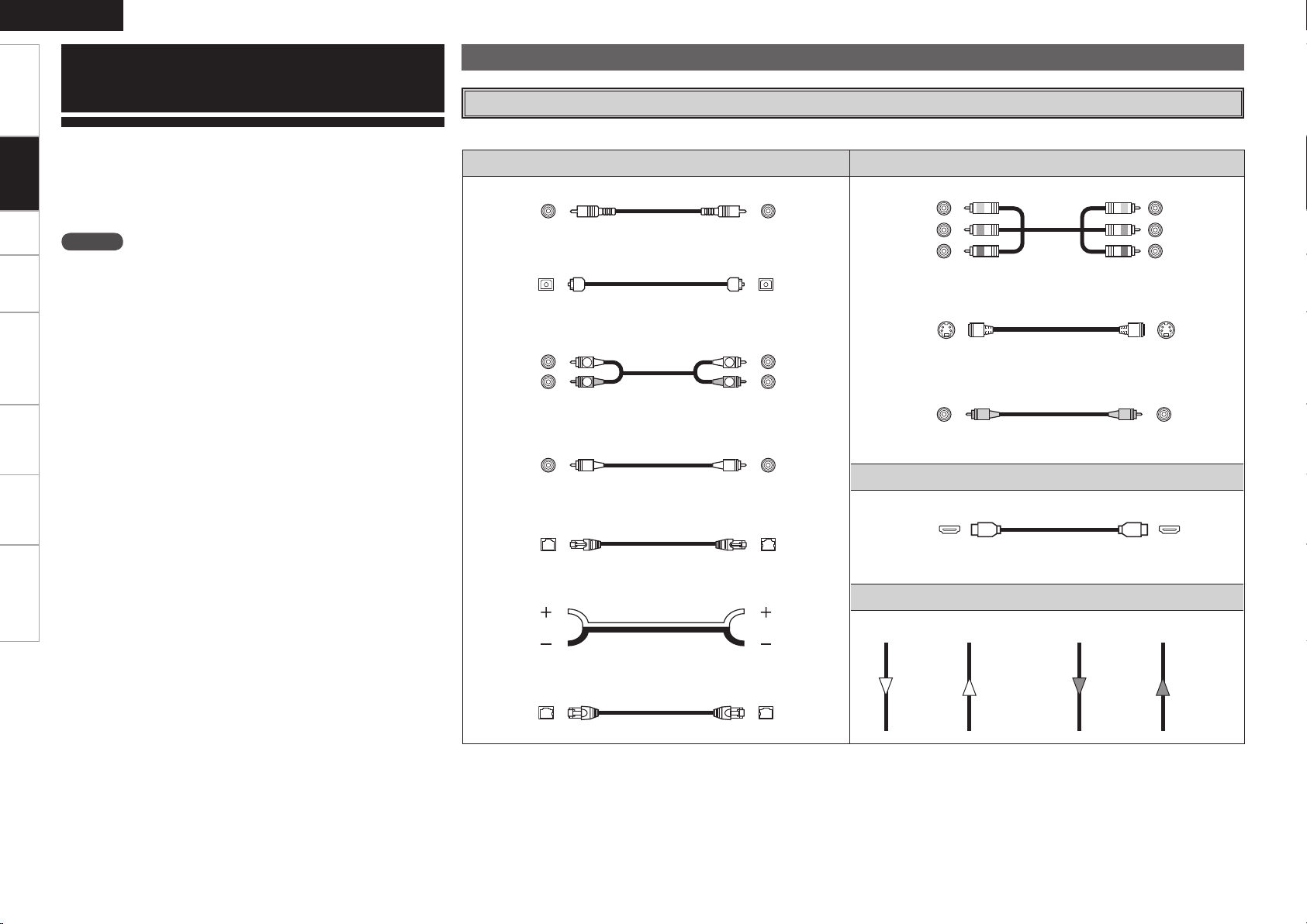
Cables Used for Connections
Select the cables according to the equipment being connected.
Audio cables Video cables
Coaxial digital connections
(Orange)
Coaxial digital (75 Ω/ohms pin-plug) cable
Optical digital connections
Optical cable
Analog connections (stereo)
(White)
(Red)
Stereo pin-plug cable
Analog connections (monaural, for subwoofer)
(Black)
Pin-plug cable
DENON LINK connections
DENON LINK cable
Component video connections
(Green)
(Blue)
(Red)
S-Video connections
Video connections
(Yellow)
Component video cable
S-Video cable
75 Ω/ohms pin-plug video cable
Audio and video cables
HDMI connections
19-pin HDMI cable
(Y)
(PB/CB)
(PR/CR)
Speaker connections
Audio signal: Video signal:
Output
Input
Speaker cables
Network connections
(wired LAN)
Ethernet cable
Signal direction
Input
Output
Output
Input
Input
Output
Page 13
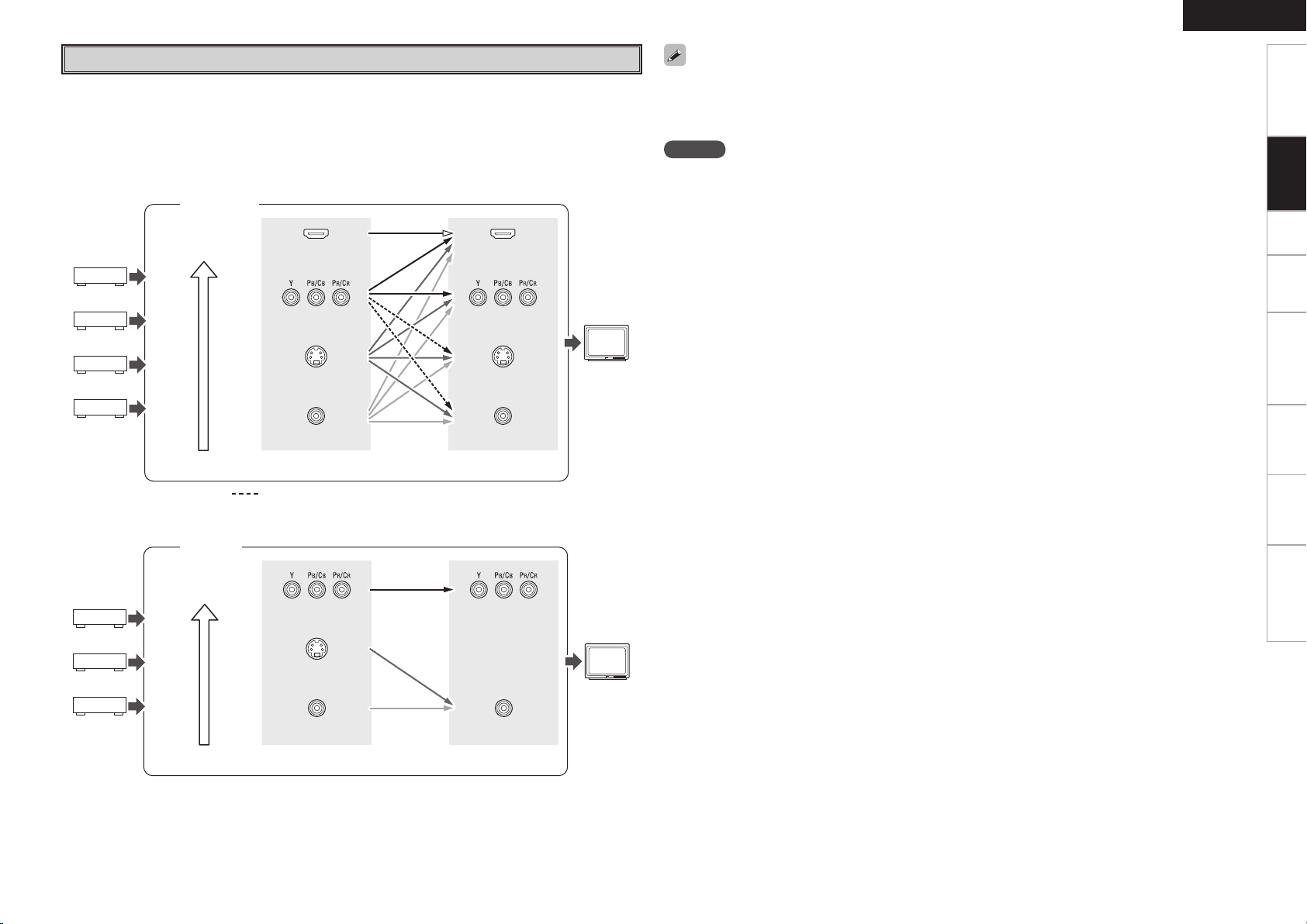
Video Conversion Function
• This function automatically converts various formats of video signals input to the AVR-4308 into the
format used to output the video signals from the AVR-4308 to a monitor.
• The AVR-4308’s video input/output circuitry is compatible with the following four types of video signals:
Digital video signals: HDMI
Analog video signals: Component video, S-Video and Video
GFlow of video signals inside the AVR-4308H
Main zone
High picture
quality playback
HDMI connector
Component video
connectors
HDMI connector
Component video
connectors
Monitor
ENGLISH
Getting Started Setup Playback Remote Control Multi-Zone Information Troubleshooting
• When not using this function, connect a monitor output with the same type of connector as the video
input connector.
• The resolution of the HDMI input-compatible monitor connected to the AVR-4308 can be checked at GUI
menu “Information” – “HDMI Information” – “Monitor1” or “Monitor2” (vpage 48).
Connections
NOTE
• HDMI signals cannot be converted into analog signals.
• 1080p component input video signals cannot be output to anything other than component video
connectors.
• 480p/576p, 1080i and 720p component video input signals cannot be converted into S-Video or Video
format.
• When using the component video output connectors for connection to the ZONE2 monitor, the ZONE2’s
on-screen display is not displayed.
• When a non-standard video signal from a game machine or some other source is input, the video
conversion function might not operate.
ZONE2
High picture
quality playback
S-Video connector
Video connector
Video inputs Video outputs
: When 480i/576i signals are input in the main zone
GFlow of video signals for ZONE2H
Component video
connectors
S-Video connector
Video connector
Video inputs Video outputs
S-Video connector
Video connector
Component video
connectors
Video connector
ZONE2
monitor
Page 14
ENGLISH
w q
w q
w q
w q w q w q w q
w q
*/
w q
(L)
(R)
(L) (R) (L) (R)
(R)
(L)
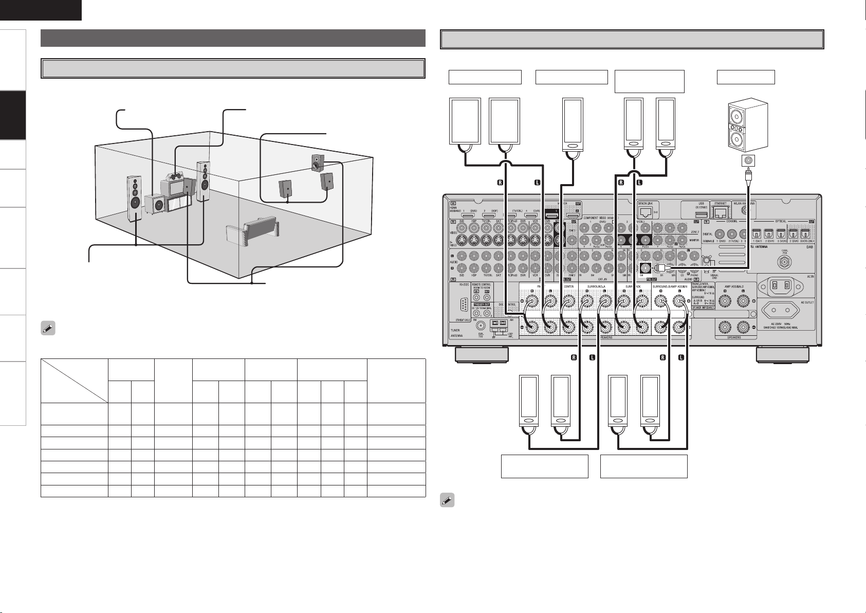
Getting Started Setup Playback Remote Control Multi-Zone Information Troubleshooting
The illustration below shows a basic example of installation of the amplifier combined with 8 speakers and
Connections
a monitor.
Front speakers
Place the front speakers to the
sides of the monitor or screen and
as flush with the screen surface as
possible.
Speaker Connections
Speaker Installation
Subwoofer Center speaker
Surround back speakers
Surround speakers
Speaker Connections
Example: 7.1-channels (Surround A+B)
Front speakers
Center speaker Subwoofer
Surround back
speakers
Subwoofer
with built-in
amplifier
The table below shows a typical speaker configuration for the AVR-4308.
SURROUND ASURROUND BSURROUND
– –
– – – –
– – – – –
– – – – – – –
– – – – – – – –
– – – – – – – – –
7.1-channels
(Surround A+B)
7.1-channels
6.1-channels
5.1-channels
3.1-channels
2.1-channels
2-channels
FRONT
CENTER
L R L R L R L R
S S S S S S S S S
S S S S S
S S S S S
S S S S S
S S S
S S
S S
0
BACK
S S
SUBWOOFER
1
only
–
–
S S
b L : Left
R : Right
S
S
S
S
S
When using just one surround back speaker, connect it to the left channel (SBL).
Surround speakers
A
Surround speakers
B
Page 15
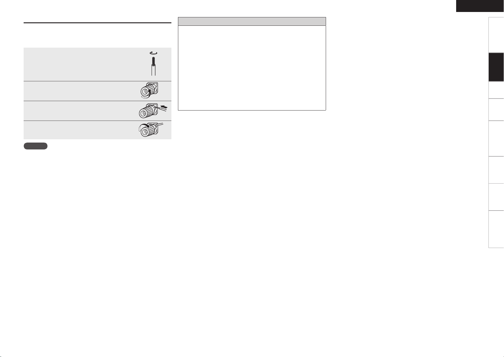
Connecting the Speaker Cables
Carefully check the left (L) and right (R) channels and + (red) and –
(black) polarities on the speakers being connected to the AVR-4308,
and be sure to interconnect the channels and polarities correctly.
Peel off about 10 mm of sheathing from
1
the tip of the speaker cable, then either
twist the core wire tightly or terminate
it.
Turn the speaker terminal
2
counterclockwise to loosen it.
Insert the speaker cable’s core wire to
3
the hilt into the speaker terminal.
Turn the speaker terminal clockwise to
4
tighten it.
NOTE
• Use speakers with an impedance of 6 to 16 Ω/ohms. When using
surround A and B speakers simultaneously, use speakers with an
impedance of 8 to 16 Ω/ohms.
• Connect the speaker cables in such a way that they do not stick out
of the speaker terminals. The protection circuit may be activated if
the core wires touch the rear panel or if the + and – sides touch each
other (v “Protection circuit”).
• Never touch the speaker terminals while the power supply is
connected. Doing so could result in electric shock.
Protection circuit
If speakers with an impedance lower than specified (for example
4 Ω/ohms speakers) are used for an extended period of time with
the volume turned up high, the temperature may rise, activating the
protection circuit.
When the protection circuit is activated, the speaker output is shut
off and the power indicator flashes red. If this happens, unplug
the power cord, then check the speaker cable and input cable
connections. If the set is extremely hot, wait for it to cool off and
improve ventilation around it. Once this is done, plug the power cord
back in and turn the set’s power back on.
If the protection circuit is activated again even though there are no
problems in the ventilation around the set nor in the connections,
the set may be damaged. Turn the power off, then contact a DENON
service center.
ENGLISH
Getting Started Setup Playback Remote Control Multi-Zone Information Troubleshooting
Connections
Page 16
ENGLISH
065
)%.*
*/
)%.*
Getting Started Setup Playback Remote Control Multi-Zone Information Troubleshooting
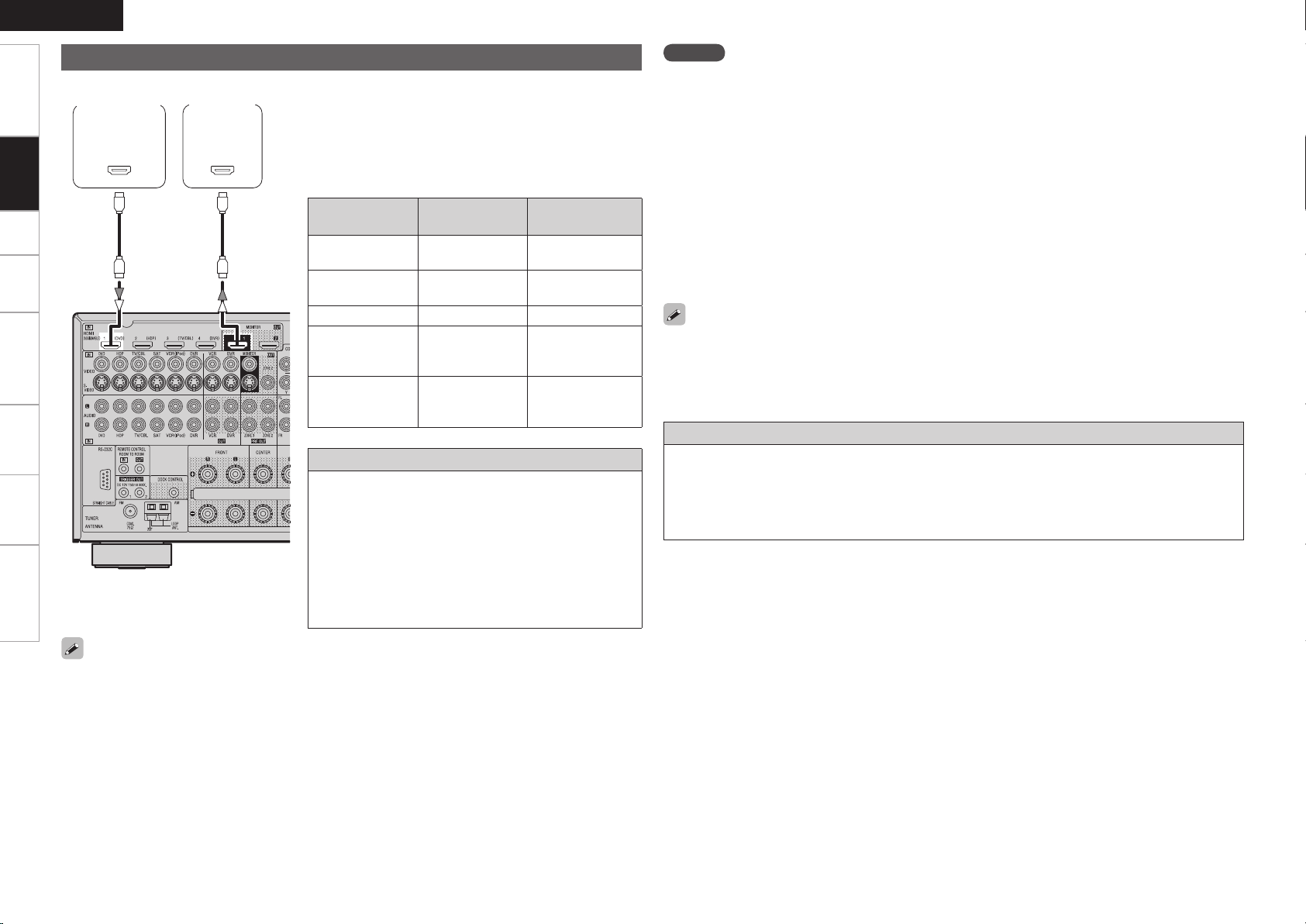
Connecting Equipment with HDMI connectors
With HDMI connections, the video and audio signals can be transferred with a single cable.
Connections
MonitorDVD player
b The AVR-4308 is equipped for HDMI version 1.3a. This
version is compatible with other versions, allowing
connection to all components equipped with an HDMI
connector.
b The AVR-4308 is compatible with 30- and 36-bit Deep
Color.
Compatible
audio format
2-channel linear
PCM
Multi-channel
linear PCM
Dolby Digital, DTS Bitstream DVD-Video
DSD
Dolby Digital Plus,
Dolby TrueHD,
DTS-HD
Details
2ch 32-192 kHz
16/20/24 bits
8ch 32-192 kHz
16/20/24 bits
2/5.1ch
2.8224 MHz
1 bit
Bitstream
Copyright protection system (HDCP)
In order to play the digital video and audio signals of a DVDVideo or DVD-Audio disc using HDMI/DVI connections, both
the connected DVD player and monitor must be equipped
for a copyright protection system called “HDCP” (Highbandwidth Digital Content Protection).
HDCP is a copy protection technology consisting of data
encoding and mutual identification of the devices.
The AVR-4308 is HDCP-compatible. For details on the
DVD player or monitor you are using, refer to its operating
instructions.
Discs
(examples)
CD, DVD-Video,
DVD-Audio
DVD-Audio
SACD
HD DVD,
Blu-ray Disc
NOTE
• Use a CPPM-compatible DVD player to play DVD-Audio discs that are copyright-protected by CPPM.
• The AVR-4308 cannot be controlled from another device via the HDMI cable.
• The audio signals output from the HDMI connector (sampling frequency, bit rate, etc.) may be restricted
by the connected device.
• Video signals are not output properly when using devices that are not HDCP-compatible.
• Video signals are not output if the input video signals do not match the monitor’s resolution. In this case,
switch the DVD player’s resolution to a resolution with which the monitor is compatible.
• If the GUI menu “Manual Setup” – “HDMI Setup” – “Audio” setting (vpage 31) is set to “Amp”, the
sound may be interrupted when the monitor’s power is turned off.
• Use a cable on which the HDMI logo is indicated (a certified HDMI product) for connection to the HDMI
connector. Normal playback may not be possible when using a cable other than one on which the HDMI
logo is indicated (a non-HDMI-certified product).
• If the monitor or DVD player does not support deep color, deep color signal transfer is not possible.
• If the monitor or DVD player does not support xvYCC, xvYCC signal transfer is not possible.
• If the monitor does not support “Auto Lipsync Correction” function, this function will not work.
• When the AVR-4308 and DVD player are connected using an HDMI cable, also connect the AVR-4308 and
monitor using an HDMI cable.
• If the connected monitor or DVD player only has a DVI-D connector, use an HDMI/DVI converter cable.
When using a DVI cable, no audio signals are transmitted.
• Use a Deep Color compatible cable for connection to Deep Color compatible devices.
When connecting with an HDMI/DVI converter cable (adapter)
• HDMI video signals are theoretically compatible with the DVI format.
When connecting to a monitor, etc., equipped with a DVI-D connector, connection is possible using an
HDMI/DVI converter cable, but depending on the combination of components in some cases the video
signals will not be output.
• When connecting using an HDMI/DVI converter adapter, the video signals may not be output properly
due to poor connections with the connected cable, etc.
• By default, the HDMI audio signals are output from the speakers connected to the AVR-4308.
• To output the sound from the TV, make the settings at GUI menu “Manual Setup” – “HDMI Setup”
– “Audio” – “TV” (vpage 31).
Page 17
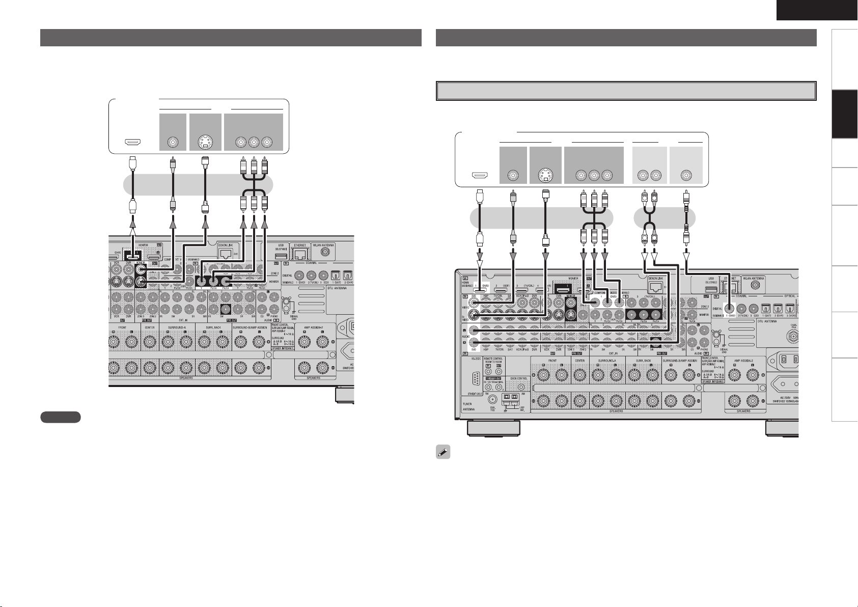
Connecting the Monitor
47*%&0
*/
7*%&0
$0.10/&/57*%&0
: 1# 13
7*%&0
*/
)%.*
*/ */
47*%&0
065
"6%*07*%&0
$0.10/&/57*%&0
: 1# 13
7*%&0
065 065
"6%*0
$0"9*"-
065
3-
065065
)%.*
R
L
R
L
• Connect the cables to be used (vpage 9 “Video Conversion Function”).
• With HDMI connections, the video and audio signals can be transferred with a single cable.
• To output the audio signals to the monitor with HDMI connections, set GUI menu “Manual Setup”
– “HDMI Setup” – “Audio” to “TV” (vpage 31).
Monitor
ENGLISH
Connecting the Playback Components
Carefully check the left (L) and right (R) channels and the inputs and outputs, and be sure to interconnect
correctly.
DVD Player
• Connect the cables to be used.
• With HDMI connections, the video and audio signals can be transferred with a single cable.
DVD player
Getting Started Setup Playback Remote Control Multi-Zone Information Troubleshooting
Connections
NOTE
• The component video connectors may be indicated differently on your monitor. For details, see the
monitor’s operating instructions.
• The audio signals output from the HDMI connectors are only the HDMI input signals.
• Connect an HDP (High-Definition Player) in the same way.
• When using an optical cable for the digital audio connection, make the settings at GUI menu “Source
Select” – “DVD” – “Assign” – “Digital” (vpage 41).
Page 18
ENGLISH
(/%
"6%*0
065
R
L
"6%*0
"6%*0
$0"9*"-
065
3-
065
R
L
R
L
"4%3
R
L
R
L
Getting Started Setup Playback Remote Control Multi-Zone Information Troubleshooting
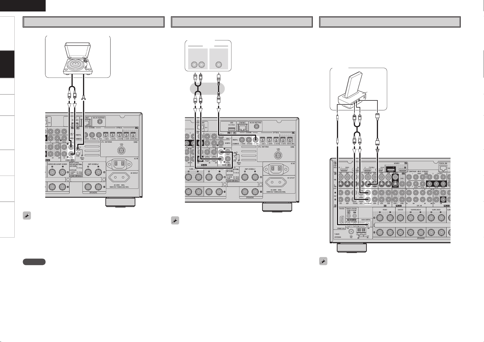
Record Player
CD Player
iPod
®
Connections
Turntable (MM cartridge)
Connect the cables to be used.
CD player
Use a DENON Control Dock for iPod (ASD-1R, sold separately) to
connect the iPod to the AVR-4308. For instructions on the Control
Dock for iPod settings, refer to the Control Dock for iPod’s operating
instructions.
Example :
iPod
• When connecting a record player with an MC cartridge, use a
commercially available MC head amplifier or a step-up transformer.
• Induction humming (a booming sound) may be produced from the
speakers if the volume is raised with no record player connected.
• With some record players, noise may be generated when the ground
wire is connected. If so, disconnect the ground wire.
NOTE
The AVR-4308’s SIGNAL GND terminal is meant to reduce noise when
a record player is connected. This is not a safety ground terminal.
When using an optical cable for the digital audio connection, make the
settings at GUI menu “Source Select” – “CD” – “Assign” – “Digital”
(vpage 41).
• With the default settings, the iPod can be used connected to the VCR
(iPod) connector.
• To assign the iPod to a connector other than VCR (iPod), make the
settings at GUI menu “Source Select” – “(input source to which iPod
dock assigned)” – “Assign” – “iPod dock” (vpage 41).
Page 19
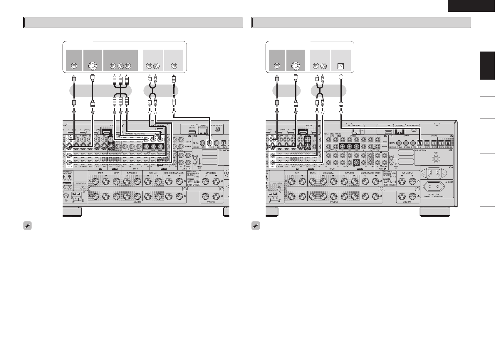
47*%&0
065
"6%*07*%&0
$0.10/&/57*%&0
: 1# 13
7*%&0
065 065
"6%*0
3-
065
$0"9*"-
065
R
L
R
L
TV/CABLE Tuner
47*%&0
065
"6%*07*%&0
7*%&0
065 065
015*$"-"6%*0
3-
065
R
L
R
L
ENGLISH
Getting Started Setup Playback Remote Control Multi-Zone Information Troubleshooting
Satellite Receiver
Connect the cables to be used.
TV tuner
Connect the cables to be used.
DBS / BS tuner
Connections
When using an optical cable for the digital audio connection, make the settings at GUI menu “Source
Select” – “TV/CBL” – “Assign” – “Digital” (vpage 41).
• When using a coaxial digital cable for the digital audio connection, make the settings at GUI menu “Source
Select” – “SAT” – “Assign” – “Digital” (vpage 41).
• When using a component video cable for the video connection, make the settings at GUI menu “Source
Select” – “SAT” – “Assign” – “Component” (vpage 41).
Page 20
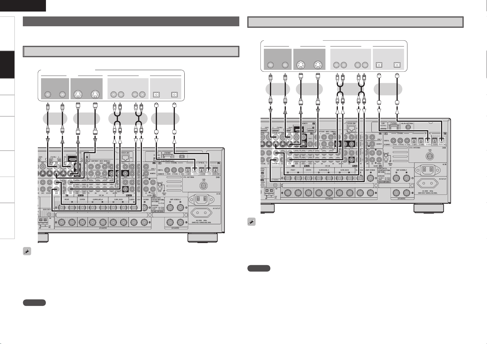
ENGLISH
47*%&0
*/
3- 3-
*/*/065
"6%*07*%&0
*/065
015*$"-
065
"6%*07*%&0
065
R
L
R
L
R
L
R
L
47*%&0
*/
3- 3-
*/*/065
"6%*07*%&0
065
"6%*07*%&0
065 */065
015*$"-
R
L
R
L
R
L
R
L
Getting Started Setup Playback Remote Control Multi-Zone Information Troubleshooting
Connecting the Recording Components
Carefully check the left (L) and right (R) channels and the inputs and outputs, and be sure to interconnect
correctly.
Video Cassette Recorder
Connect the cables to be used.
Video cassette recorder
Connections
Digital Video Recorder
Connect the cables to be used.
Digital video recorder
or or
or
or
• Make analog connections if you wish to record analog audio signals.
• When recording via the AVR-4308, the playback device’s cable must be of the same type as the cable
used to connect the AVR-4308’s DVR OUT connector.
Example: TV IN → S-Video cable : DVR OUT → S-Video cable
TV IN → Video cable : DVR OUT → Video cable
• When using a component video cable for the video connection, make the settings at GUI menu “Source
Select” – “DVR” – “Assign” – “Component” (vpage 41).
NOTE
Do not connect the output of the component connected to the AVR-4308’s OPTICAL2 output connector to
any input connector other than OPTICAL2.
• When recording via the AVR-4308, the playback device’s cable must be of the same type as the cable
used to connect the AVR-4308’s VCR OUT connector.
Example: TV IN → S-Video cable : VCR OUT → S-Video cable
TV IN → Video cable : VCR OUT → Video cable
• When using a component video cable for the video connection, make the settings at GUI menu “Source
Select” – “VCR” – “Assign” – “Component” (vpage 41).
NOTE
Do not connect the output of the component connected to the AVR-4308’s OPTICAL3 output connector to
any input connector other than OPTICAL3.
Page 21
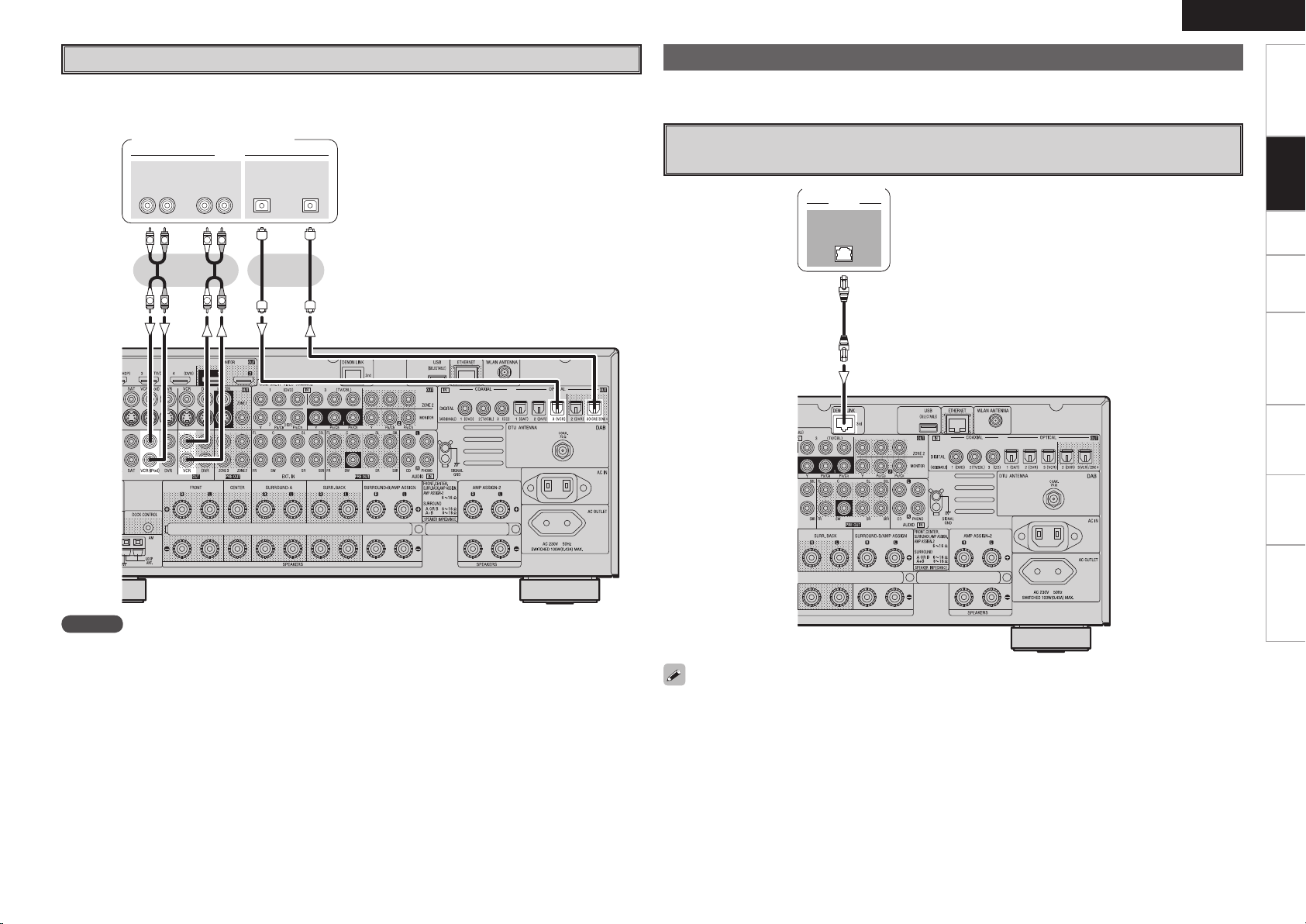
3- 3-
065 */065
015*$"-
*/
"6%*0
"6%*0
R
L
R
L
R
L
R
L
CD Recorder / MD Recorder / Tape Deck
%&/0/-*/,
"6%*0
Make analog connections if you wish to record analog audio signals, or digital connections if you wish to
record digital audio signals, depending on the types of connectors on the components being used.
CD recorder /
MD recorder / Tape deck
or
ENGLISH
Connections to Other Devices
Carefully check the left (L) and right (R) channels and the inputs and outputs, and be sure to interconnect
correctly.
Components Equipped with a DENON LINK connector
Multi-channel playback is possible with DVD-Audio discs, Super Audio CD, etc.
DVD player
Getting Started Setup Playback Remote Control Multi-Zone Information Troubleshooting
Connections
NOTE
Do not connect the output of the component connected to the AVR-4308’s OPTICAL3 output connector to
any input connector other than OPTICAL3.
To use with DENON LINK connections, make the settings at GUI menu “Source Select” – “Assign” –
“Digital” – “DENON LINK” (vpage 41).
Page 22
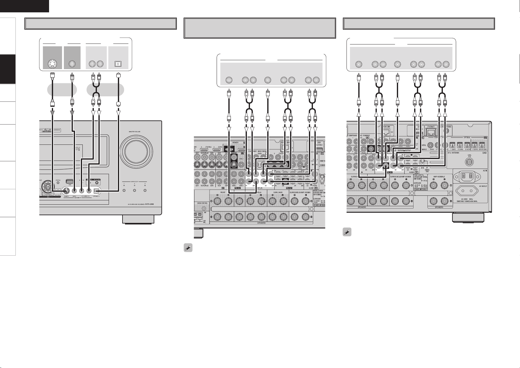
ENGLISH
47*%&0
065
"6%*07*%&0
7*%&0
065 065
015*$"-"6%*0
3-
065
R
L
R
L
46#
800'&3
$&/5&3 463306/%
#"$,
3-
463306/%
3-
'30/5
3-
"6%*0
R
L
R
L
R
L
R
L
R
L
R
L
46#
800'&3
$&/5&3 463306/%
#"$,
3-
463306/%
3-
'30/5
3-
"6%*0
R
L
R
L
R
L
R
L
R
L
R
L
Getting Started Setup Playback Remote Control Multi-Zone Information Troubleshooting
Video Camera / Game Console
Video camera / Game console
Connections
Component with Multi-channel Output
External Power Amplifier
connectors
Power amplifier
DVD player /
Super Audio CD player / External decoder
When using just one surround back speaker, connect it to the left
channel (SBL).
• To play the analog input signals input to the EXT. IN connectors,
press the INPUT MODE button on the main unit or INPUT button
on the main remote control unit and select “EXT. IN” or make the
settings at GUI menu “Source Select” – “(input source)” – “Input
Mode” – “Input Mode” – “EXT. IN” (vpage 40).
• The video signal can be connected in the same way as a DVD player
(vpage 13).
• To play copyright-protected discs, connect the AVR-4308’s EXT.
IN connector with the DVD player’s analog multi-channel output
connector.
Page 23
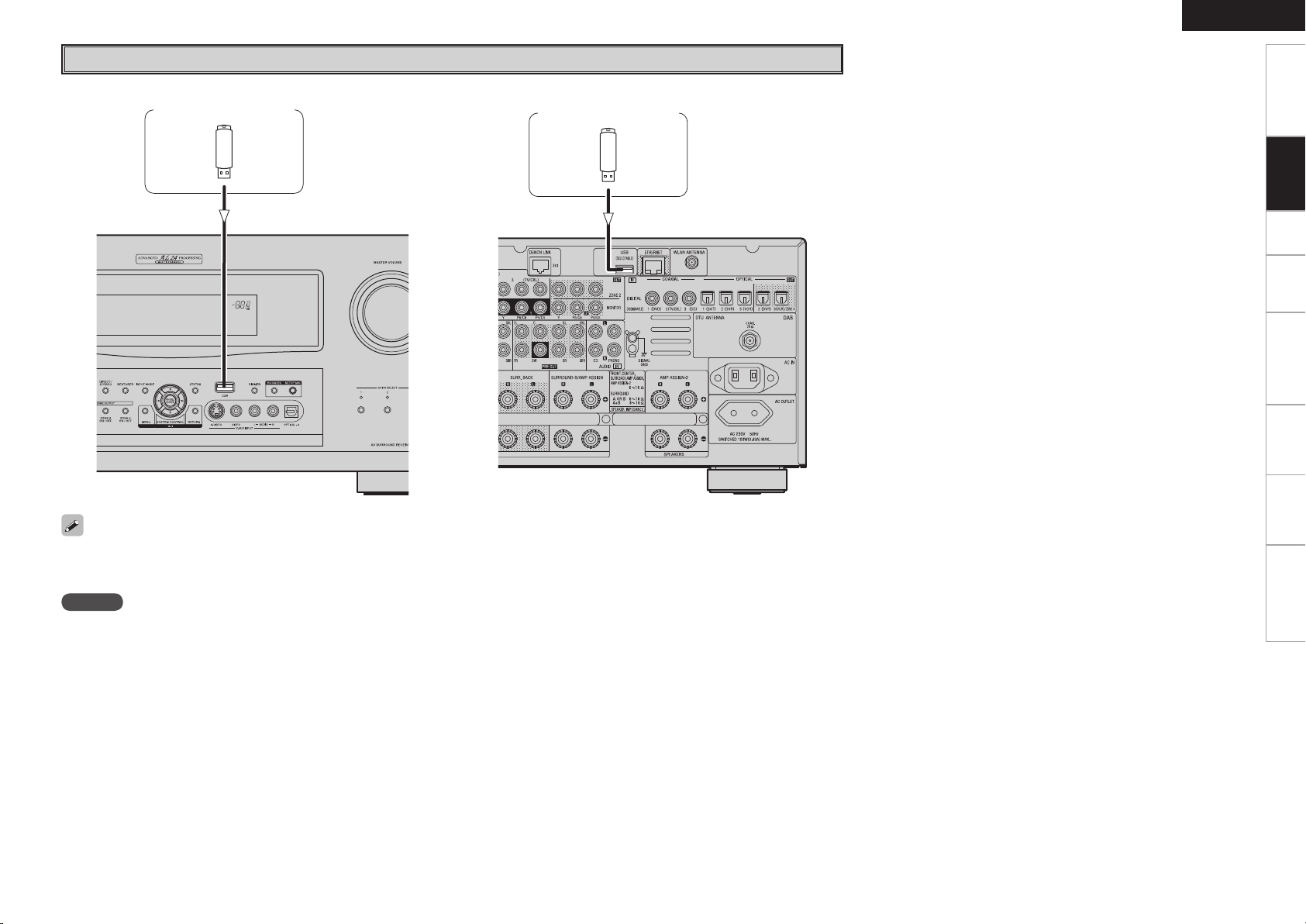
USB Port
n Front panel n Rear panel
USB memory device USB memory device
ENGLISH
Getting Started Setup Playback Remote Control Multi-Zone Information Troubleshooting
Connections
• In the initial status, USB memory devices can be used by connecting them to the USB port on the front panel.
• To change the port to be used, see “USB Select” on page 41.
• For instructions on playing the files on a USB memory device, see page 60, 61.
NOTE
• Set to the USB port you want to use.
• The AVR-4308 is equipped with two USB ports, one each on the front and rear panels. It is not possible to use the set with USB memory
devices connected to both the ports at the same time. Select the USB port you want to use at the GUI menu “Source Select” – “NET/USB” –
“Playback Mode” – “USB Select”.
• Do not use the extension cable for connecting the USB memory device to the AVR-4308’s USB port.
Use of the extension cable may cause harmful interference.
Page 24
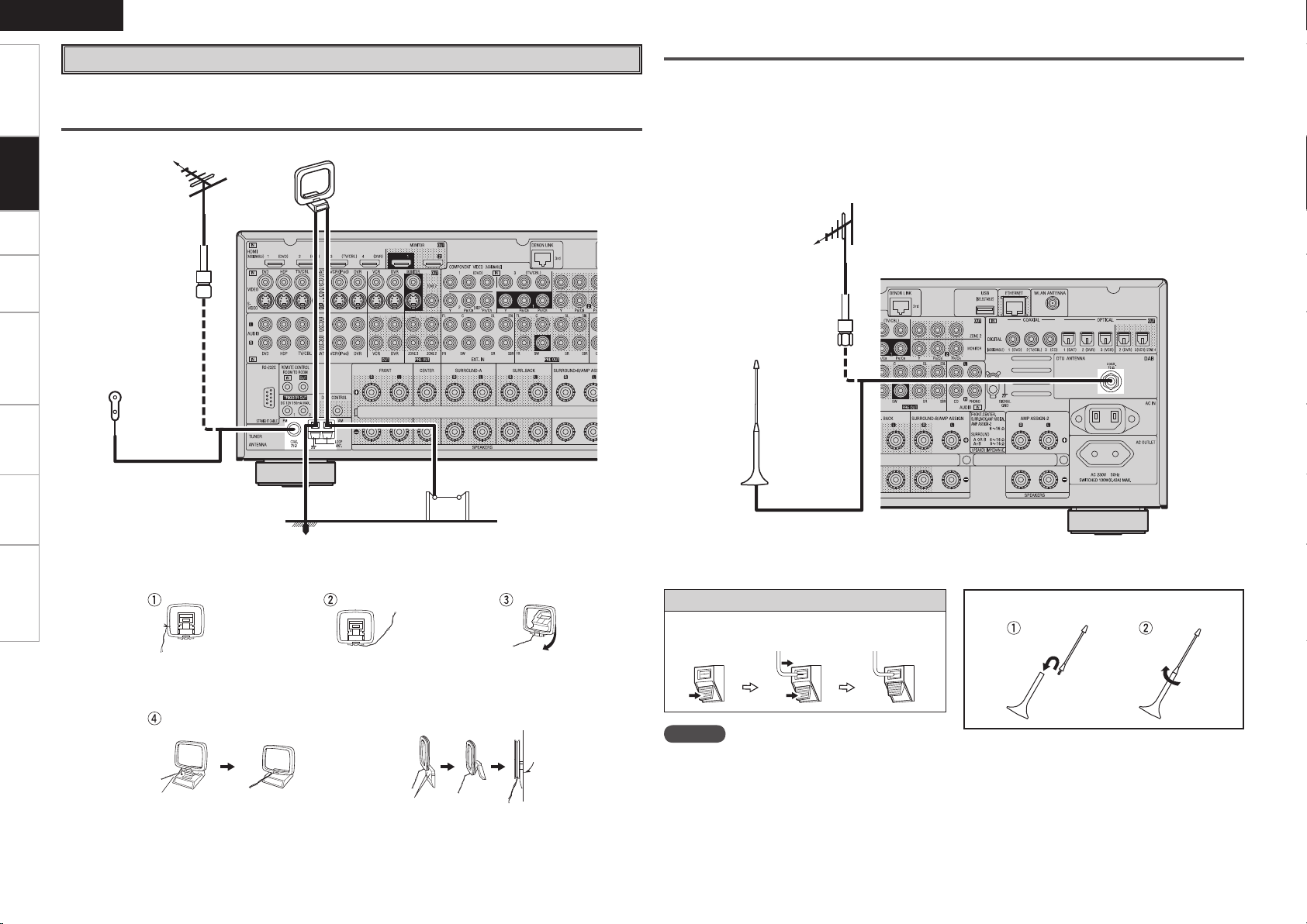
ENGLISH
Getting Started Setup Playback Remote Control Multi-Zone Information Troubleshooting
Antenna terminals
An FM antenna cable plug can be connected directly.
AM/FM
Connections
Direction of broadcasting station
FM antenna
75 Ω/ohms
Coaxial cable
FM indoor antenna
(supplied)
AM loop antenna
(supplied)
DAB
Connecting an DAB outdoor antenna
If good reception cannot be achieved with the included DAB indoor antenna, use an DAB outdoor antenna.
Connect an F male type connector to the coaxial cable and connect the antenna to the DAB COAX 75
Ω/ohms terminal.
Installing the DAB indoor antenna
q DAB station reception (vpage 54).
w Use “Tuning Aid” to set position at which reception sensitivity is optimum (vpage 42).
DAB outdoor antenna
DAB indoor antenna
(supplied)
AM loop antenna assembly
Remove the vinyl tie and take
out the connection line.
a. With the antenna on top of
any stable surface.
Mount
0
Ground
AM outdoor antenna
Connect to the AM
antenna terminals.
Bend in the reverse direction.
b. With the antenna attached
to a wall.
Installation hole Mount on wall, etc.
Connection of AM antennas
1. Push the
lever.
2. Insert the
conductor.
3. Return the
lever.
NOTE
• Do not connect two FM antennas
simultaneously.
• Even if an external AM antenna is used, do not
disconnect the AM loop antenna.
• Make sure the AM loop antenna lead terminals do
not touch metal parts of the panel.
DAB indoor antenna assembly
Mount the antenna’s screw to the stand.
Page 25
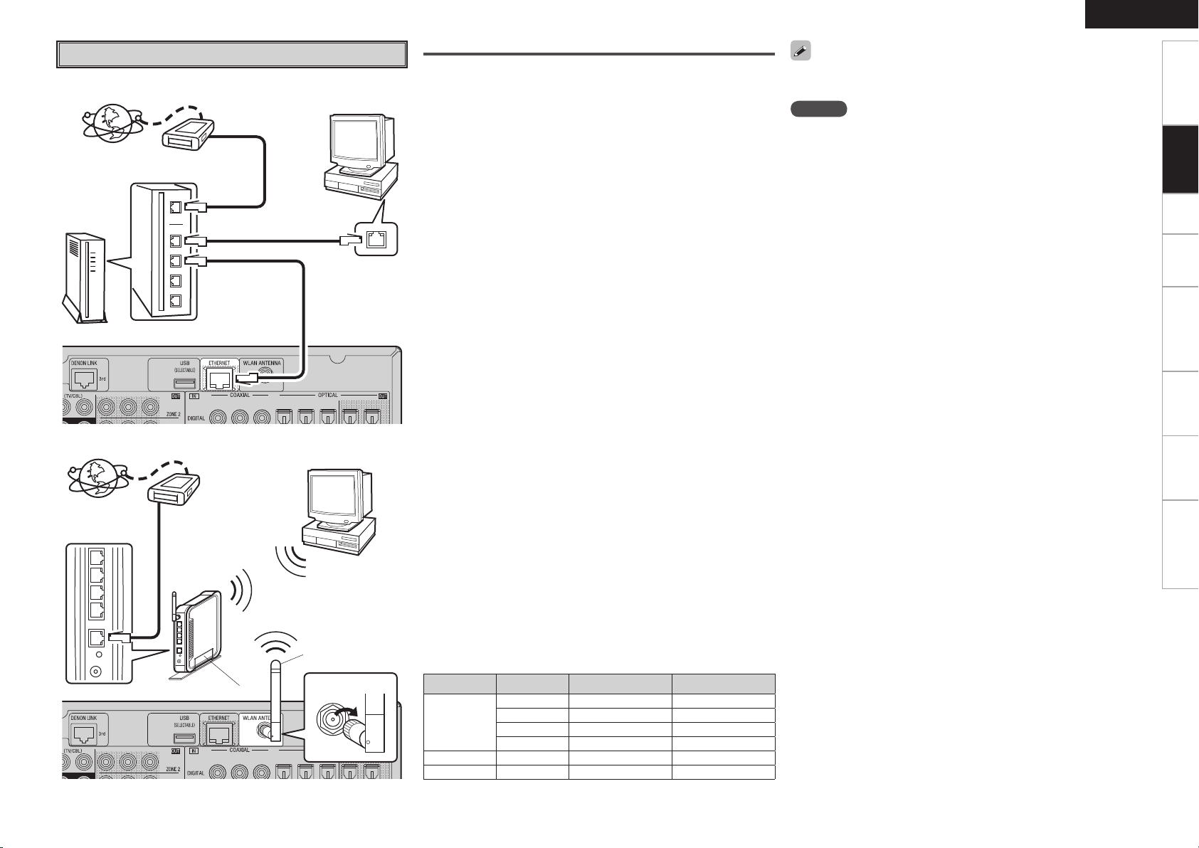
Network Audio
[Wired LAN]
Internet
Router
[Wireless LAN]
Internet
Router with access point
To WAN side
To LAN port
To LAN port
Modem
To WAN side
Modem
Computer
LAN port/Ethernet
connector
Computer
Rod antenna
(supplied)
Turn clockwise.
Required system
n Broadband Internet connection
A broadband line connection to the Internet is required in order to
use the AVR-4308’s Internet radio function and firmware update.
n Modem
This is a device that is connected to the broadband line to
communicate with the Internet. Some are integrated with the
router.
n Router
• When using the AVR-4308, we recommend you use a router
equipped with the following functions:
· Built-in DHCP (Dynamic Host Configuration Protocol) server
This function automatically assigns IP addresses on the LAN.
· Built-in 100BASE-TX switch
When connecting multiple devices, we recommend a switching
hub with a speed of 100 Mbps or greater.
• When using with a wireless LAN, prepare a broadband router with
built-in access point.
n Ethernet cable (CAT-5 or greater recommended)
Use for wired LAN.
• The AVR-4308 does not come with an Ethernet cable.
• Some flat type Ethernet cables are easily affected by noise.
We recommend using a normal type cable.
• For the Ethernet cable, used a shielded twisted pair (STP) cable.
Do not use an unshielded twisted pair (UTP) cable, as it may exceed
noise standard limits.
n Computer
A computer with the following specifications is required to use a
music server:
• OS
Windows® XP Service Pack2, Windows Vista
• Software (Prepare one of the following.)
· .NET Framework 1.1 and Windows Media Connect (Windows XP)
· Windows Media Player ver.11
· DLNA-compatible server software
• Internet browser
Microsoft Internet Explorer 5.01 or later
• LAN port
• 300 MB or more free disk space
b Free disk space is required to store music and video files. The
following sizes are approximate.
Format Bit rate Per minute Per hour
MP3 / WMA
MPEG-4 AAC
WAV (LPCM)
FLAC
128 kbps Approx. 1 MB Approx. 60 MB
192 kbps Approx. 1.5 MB Approx. 90 MB
256 kbps Approx. 2 MB Approx. 120 MB
392 kbps Approx. 3 MB Approx. 180 MB
1400 kbps Approx. 10 MB Approx. 600 MB
1080 kbps Approx. 7.7 MB Approx. 464 MB
ENGLISH
For connections to the Internet, contact an ISP (Internet Service
Provider) or a computer shop.
NOTE
• A contract with an ISP is required to connect to the Internet.
No additional contract is needed if you already have a broadband
connection to the Internet.
• The types of routers that can be used depend on the ISP. Contact an
ISP or a computer shop for details.
• Depending on the server, video files may be displayed, but they
cannot be played on the AVR-4308.
n Others
• If you have an Internet provider contract for a line on which network
settings are made manually, make the settings at GUI menu
“Manual Setup” – “Network Setup” (vpage 33 ~ 35).
• With the AVR-4308, it is possible to use the DHCP and Auto IP
functions to make the network settings automatically.
• When using a broadband router (DHCP function), the AVR-4308
sets the IP address, etc., automatically.
When using the AVR-4308 connected to a network with no DHCP
function, make the settings for the IP address, etc., at GUI menu
“Manual Setup” – “Network Setup” (vpage 33 ~ 35).
• The AVR-4308 is not compatible with PPPoE. A PPPoE-compatible
router is required if you have a contract for a line of the type with
which the PPPoE is set.
• Depending on the ISP with which you have your contract, it may
be necessary to make proxy server settings to use the Internet
radio function. If you made proxy server settings on the computer
to connect to the Internet, make the proxy server settings on the
AVR-4308 in the same way.
Getting Started Setup Playback Remote Control Multi-Zone Information Troubleshooting
Connections
Page 26
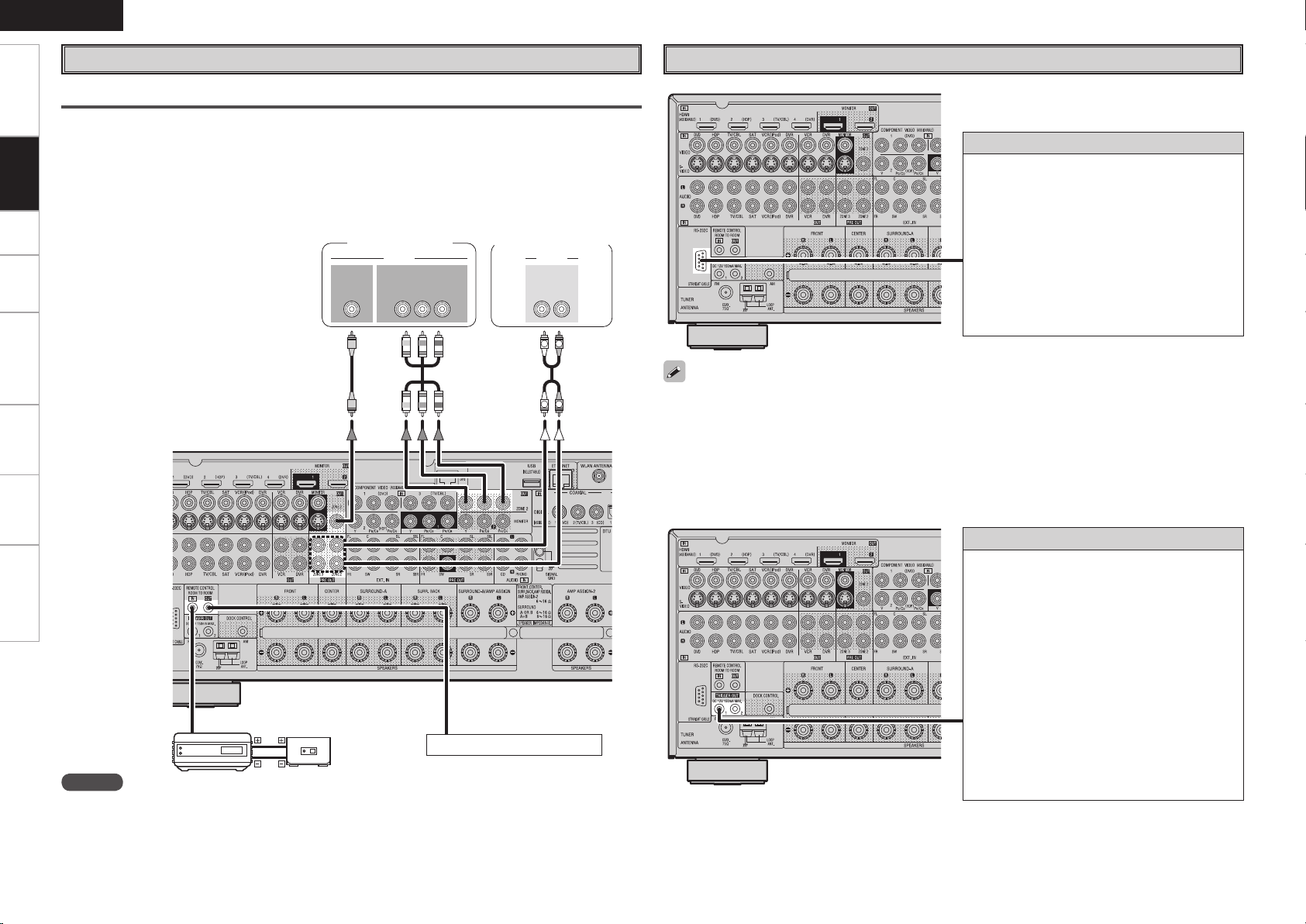
ENGLISH
R
L
R
L
"69
065
"6%*0
3-
*/*/
7*%&0
"6%*07*%&0
$0.10/&/57*%&0
: 1# 13
*/
Getting Started Setup Playback Remote Control Multi-Zone Information Troubleshooting
Multi Zone
ZONE2 or ZONE3 Pre-out Connections
• If another power amplifier or pre-main (integrated) amplifier is connected, the ZONE2 or ZONE3 pre-out
Connections
(variable or fixed level) connectors can be used to play a different program source in ZONE2 or ZONE3
the same time (vpage 73 ~ 77).
• When using a component video cable to connect the AVR-4308 and input device, connect the ZONE2
monitor output to the component video connectors. When using an S-Video cable or a video cable, please
connect the cable to the video connectors.
• The ZONE2 video out is only for ZONE2.
Monitor (ZONE2)
Power amplier
(ZONE2 or ZONE3)
External Controller
RS-232C connector
This connector is used for an external controller.
b If you wish to control the AVR-4308 from
an external controller using the RS-232C
connector, perform the operation below
beforehand.
q Turn the AVR-4308’s power.
w Turn off the AVR-4308’s power from the
external controller.
e Check that the AVR-4308 is in the standby
mode.
Infrared
retransmitter
Input
Output
Infrared
sensor
Extension jack for future use.
NOTE
• For the audio output, use high quality pin-plug cords so that no induction humming or noise is produced.
• For instructions on installing and operating separately sold devices, refer to the respective devices’
operating instructions.
• To conduct multi-zone playback, see “Amp Assign / Multi-Zone Connections and Operations” (vpage
73 ~ 77).
• When using in combination with an RF Remote Controller (RC-7000CI, sold separately) or RF Remote
Receiver (RC-7001RCI, sold separately) two-way communication with an RF Remote Controller is
possible.
The AVR-4308’s status information as well as iPod and Internet audio music files can be browsed watching
the RF Remote Controller’s display. For details, refer to the operating instructions of the respective
devices.
• When used in combination with an RF Remote Controller or RF Remote Receiver, make the settings at
GUI menu “Manual Setup” – “Option Setup” – “2Way Remote” – “Used” (vpage 37).
Trigger output jacks
The power of an external device equipped with
a trigger input jack can be turned on and off in
association with operations on the AVR-4308. For
details, see GUI menu “Manual Setup” – “Option
Setup” – “Trigger Out 1” or “Trigger Out 2”
(vpage 37).
• Output level: 150 mA/12 V
Check the trigger input conditions of the
connected device.
• If the trigger input level of the connected device
is higher than 150 mA/12 V and depending on
the short-circuiting conditions, the AVR-4308’s
protection circuit may be activated, in which case
“TRIGGER PROTECT” appears on the display. If
this happens, turn off the AVR-4308’s power and
disconnect the connected device.
Page 27
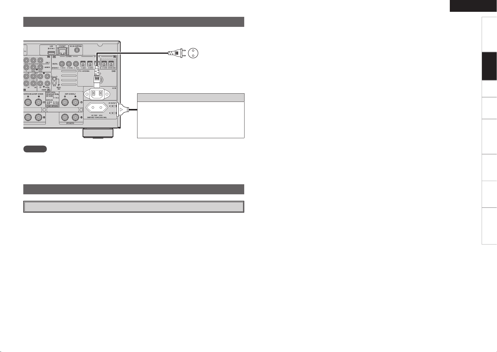
Connecting the Power Cord
Wait until all connections have been completed before connecting the power cord.
ENGLISH
Getting Started Setup Playback Remote Control Multi-Zone Information Troubleshooting
To household
Power cord
(included)
power outlet
(AC 230 V, 50 Hz)
Connection to the AC outlet
• This outlet supply power to external audio
devices.
• The power supplied from these outlets turns on
and off together with the set’s power switch.
• Audio equipment with a total power consumption
of 100 W (0.43 A) can be connected.
NOTE
• Insert the AC plugs securely. Incomplete connections could cause noise.
• Only use the AC outlet to plug in audio devices. Do not use them as power supplies for hairdryers or
anything other than audio equipment.
Once Connections are Completed
Turning the Power On (vpage 49)
Connections
Page 28
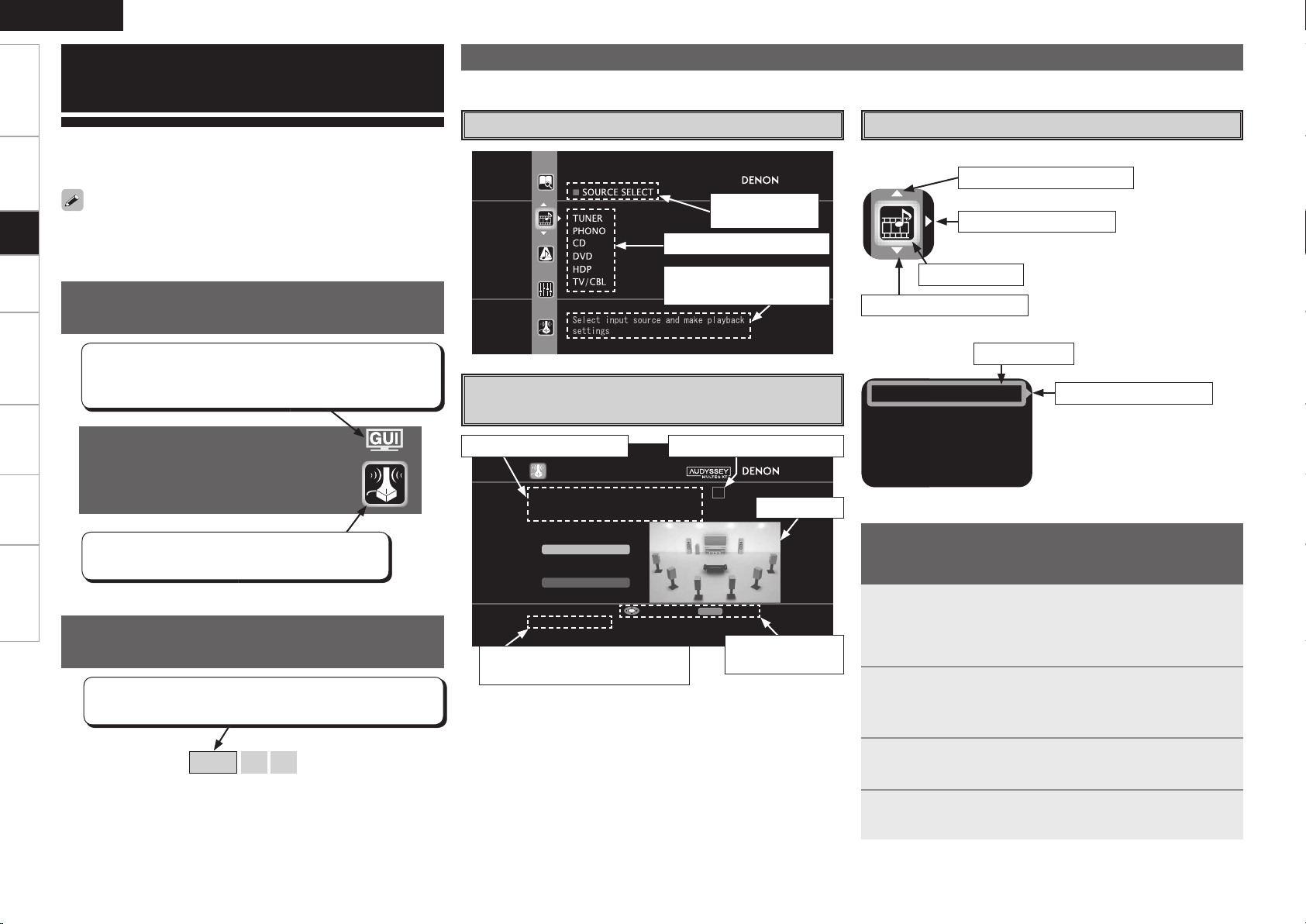
ENGLISH
AUTO S ETUP
1 2 3 4 5
Start
RETURN
Amp As sign
Config 7.1(B)
STEP1 Speaker Det ection
Please place the microphone at ear
height at main li stening position.
Start Auto Setup
Enter Cancel
Assign
Input Mode
Rename
Other
Getting Started Connections Playback Remote Control Multi-Zone Information Troubleshooting
GUI Menu Operations
With the AVR-4308, settings and operations for most functions can be
performed by operating while looking at the GUI menus displayed on
the monitor screen.
Setup
The GUI cannot be superimposed when xvYCC signals and component
1080p signal, computer’s resolution (e.g. VGA) are input.
Examples of GUI Screen Displays
Some typical examples are described below.
Example: Browse Menu (Top Menu)
Selected item
name
List of subsequent items
Cursor Position Display
n Icon
Switch the selected item
Switch to the next item
Example of the Display of the GUI
Mark at a Title
Example of Display of Default
Values
[Selectable items] 7.1 (B) 7.1 5.1
Items for which this mark is indicated at the title can be
operated from the GUI.
We recommend performing such operations from the GUI.
Auto Setup
Optimize settings for speakers in use.
This is the GUI icon for this setting item or for the
menu series to which this item belongs.
In lists of selectable items or adjustable ranges, the item
surrounded by a border is the default value.
Guidance text for item at
cursor position
Example: Menus with Illustrations
(Auto Setup)
Operation guidance text
Guidance text for item at cursor
position
Operation step indicators
Illustration
Operation
button guidance
Selected item
Switch the selected item
n List
Selected item
Switch to the next item
b Switch the selected item using
ui.
Operations
The same operation is possible on the main unit or remote control
unit.
Press the MENU button.
The GUI menu is displayed.
1
b To operate from the main remote control unit, be sure to set the
remote control unit to the AMP mode.
Press the u i p button to select the menu to be set
2
or operated.
b To return to the previous item, press the o or RETURN button.
Press the ENTER button to enter the setting.
3
Press the MENU button to fi nish.
4
Page 29
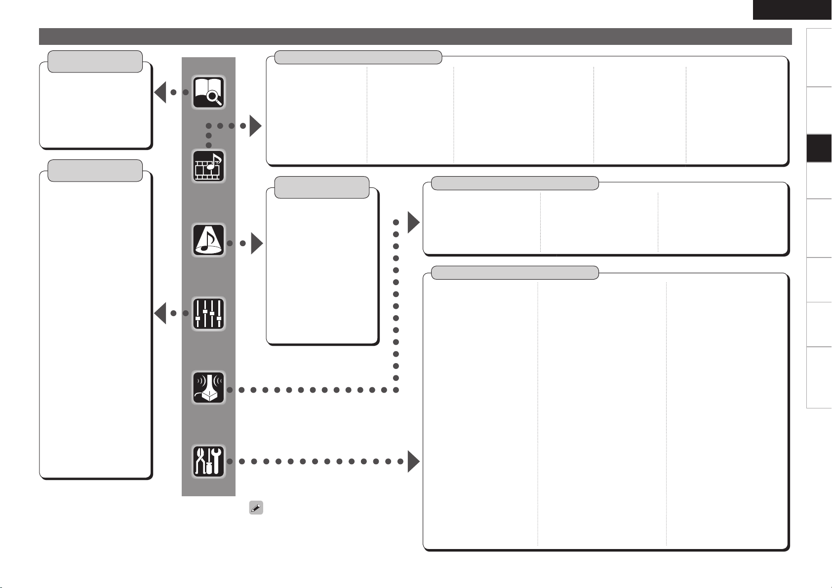
GUI Menu Map
ENGLISH
Getting Started Connections Playback Remote Control Multi-Zone Information Troubleshooting
Information
(vpage 47, 48)
n Status
• MAIN ZONE
• ZONE2/3/4
n Audio Input Signal
n HDMI Information
n Auto Surround Mode
n Quick Select
n Preset Station
Parameter
(vpage 44 ~ 47)
n Audio
• Surround Parameters
· Mode
· Cinema EQ
· DRC
· D.COMP
· LFE
· Center Image
· Panorama
· Dimension
· Center Width
· Delay Time
· Effect
· Effect Level
· Room Size
· AFDM
· SB CH Out
· Subwoofer Att.
· Subwoofer
· Default
• Tone
· Tone Defeat
· Bass
· Treble
• Room EQ
• RESTORER
• Night Mode
• Audio Delay
n Picture Adjust
• Contrast
• Brightness
• Chroma Level
• Hue
Source Select
n TUNER (FM/AM)
• Play
• Auto Preset
• Preset Skip
• Preset Name
• Input Mode
• Rename
• Other
· Video Select
· Source Level
(vpage 38 ~ 42)
n PHONO
• Input Mode
• Rename
• Other
· Video Select
· Source Level
Surround Mode
(vpage 43, 44)
n STEREO
n DIRECT
n STANDARD
n DOLBY PLIIx, DOLBY PLII or
DOLBY PL
n DTS NEO:6
n 7CH STEREO
n WIDE SCREEN
n SUPER STADIUM
n ROCK ARENA
n JAZZ CLUB
n CLASSIC CONCERT
n MONO MOVIE
n VIDEO GAME
n MATRIX
n VIRTUAL
When “Screensaver” is set to “ON”, the
screensaver is activated if no operation is
performed for about 3 minutes.
n CD, DVD, HDP, TV/CBL,
SAT, VCR, DVR, V.AUX
• Play (iPod)
• Playback Mode (iPod)
• Assign
• Input Mode
• Rename
• Other
· Video Select
·
Video Convert (Excluding CDs)
· Source Level
Auto Setup
n Auto Setup
• STEP1: Speaker Detection
• STEP2: Measurement
• STEP3: Calculation
• STEP4: Check
• STEP5: Store
Manual Setup
n Speaker Setup
(vpage 29, 30)
• Speaker Confi guration
• Subwoofer Mode
• Distance
• Channel Level
• Crossover Frequency
• Surround Speaker
n HDMI Setup (vpage 31)
• i/p Scaler
• Resolution
• Progressive Mode
• Aspect
• Color Space
• RGB Range
• Auto Lip Sync
• Audio
• Monitor Out
n Audio Setup (vpage 32, 33)
• EXT. IN Setup
· Surround Speaker
· Subwoofer Level
• 2ch Direct/Stereo
• Downmix Option
• Auto Surround
• Manual EQ
(vpage 26 ~ 28)
(vpage 29 ~ 38)
n NET/USB
• Play
• Playback Mode
• Still Picture
• Input Mode
• Rename
• Other
· Video Select
· Source Level
n Option
• Room EQ
• Direct Mode
• Mic Select
n Network Setup (vpage 33 ~ 35)
• Network Setup
• Other
· Power Saving
· Character
· PC Language
• Network Information
n Zone Setup (vpage 35)
• ZONE2
· Bass
· Treble
· HPF
· Lch Level
· Rch Level
· Channel
· Volume Level
· Volume Limit
· Power On Level
· Mute Level
• ZONE3
· Bass
· Treble
· HPF
· Lch Level
· Rch Level
· Channel
· Volume Level
· Volume Limit
· Power On Level
· Mute Level
n DAB
• Play
• Auto Tune
• Preset Skip
• Tuning Aid
• DRC Value
• Input Mode
• Rename
• Other
· Video Select
· Source Level
n Parameter
• Speaker Confi guration Check
• Distance Check
• Channel Level Check
• Crossover Check
• EQ Check
• Restore
n Option Setup (vpage 36 ~ 38)
• Amp Assign
• Volume Control
· Volume Limit
· Power On Level
· Mute Level
• Source Delete
• GUI
· Screensaver
· Wall Paper
· Format
· Text
· Master Volume
· NET/USB
· iPod
· Tuner
• Quick Select Name
• Trigger Out 1
• Trigger Out 2
• Digital Out
• Remote ID
• 2Way Remote
• Dimmer
• Setup Lock
• Maintenance Mode
• Firmware Update
n Language (vpage 38)
Setup
Page 30
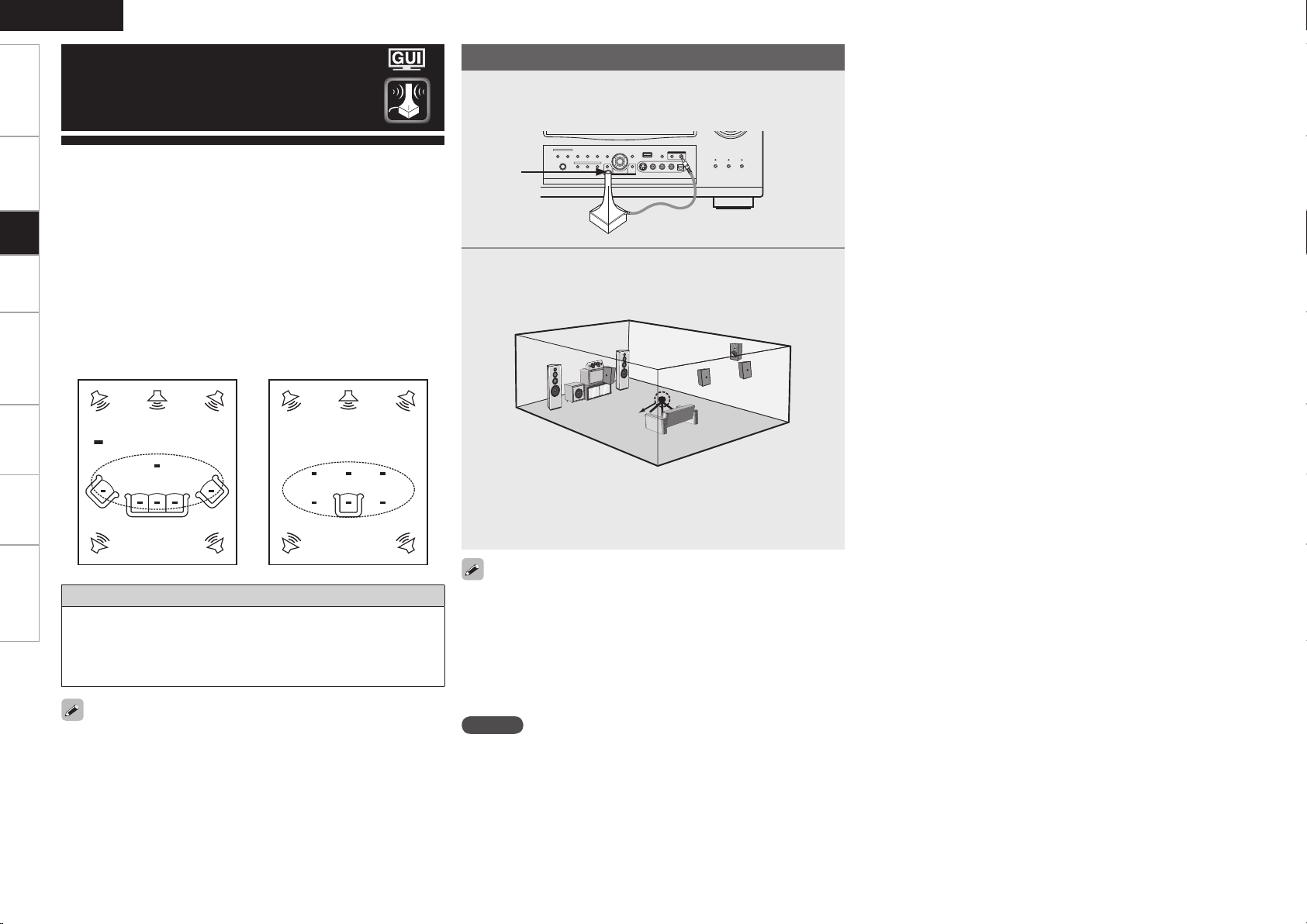
ENGLISH
*
M
*
M
Getting Started Connections Playback Remote Control Multi-Zone Information Troubleshooting
Auto Setup
Preparations
Connect the included calibrated setup microphone to
1
the SETUP MIC jack on the main unit.
The auto setup screen appears automatically.
• Audyssey MultEQ® XT automatically measures the acoustical
problems in the listening environment to create the best audio
experience for your home theater.
• It optimizes a large listening area where one or more listeners are
Setup
seated.
Measurements are performed by placing the calibrated microphone
(DM-A505Z) successively at multiple positions throughout the
listening area as shown in Example q. For best results, it is
strongly recommended to measure 6 or more positions so that the
measurements have the proper spatial weighting.
Even if the listening environment is small as shown in Example w,
measuring at multiple points throughout the listening environment
results in more effective correction.
Example q Example w
( :Measuring positions)
About the main listening position (*M)
The main listening position refers to the most central position where
one would normally sit within the listening environment.
MultEQ XT uses the measurements from this position to calculate
speaker distance, level, polarity, and the optimum crossover value
for the subwoofer.
To make manual adjustments to the settings, see page 29 ~ 31.
Sound
receptor
Place the microphone at ear height on a tripod or stand
2
with the microphone pointing directly up towards the
ceiling.
Setup
microphone
b It is not recommended to hold it in your hand. Be sure that the
path from microphone to the speakers is not blocked by objects.
Avoid placing the microphone close to a seat back or wall as sound
refl ections may give inaccurate results.
When using a subwoofer, make the following settings before starting
the auto setup procedure:
• Defeat the volume and crossover controls if possible
• If this is not possible then set
•
Volume: “12 o’clock” position
•
Crossover frequency: “Maximum/Highest Frequency”
•
Low pass fi lter: “Off”
•
Standby mode: “Off”
NOTE
• Do not disconnect the setup microphone until the auto setup
procedure is completed.
• When using headphones, unplug the headphones before starting
the auto setup procedure.
Page 31

Auto Setup
Optimize settings for speakers in use.
F Menu tree F
Auto Setup
a Auto Setup
s Option
d Parameter
a Auto Setup
The settings are performed automatically.
GAuto setup fl owH
STEP1: Speaker Detection
STEP2: Measurement (2 to 8 positions)
STEP3: Calculation
STEP4: Check
STEP5: Store
Start
Start Auto Setup.
The Audyssey MultEQ XT Auto Setup process automatically calculates
the size, level, distance, bass management crossover frequency, and
optimal settings for each speaker and subwoofer. Audyssey MultEQ
XT corrects acoustical distortions within the listening area.
Before starting, connect and position all your speakers.
Once started, MultEQ XT will play a series of test tones through each
speaker.
Confi guration
The speaker system to be measured can be selected ahead of time
here.
[Selectable items]
Setting the correct speaker confi guration can reduce the time required
to measure during the auto setup procedure as the system will not
have to look for speakers that are not connected.
7.1 (B) 7.1 5.1
Amp Assign
Advanced setting : changes power amplifi er assignment.
NOTE
The items selectable at “Confi g.” differ according to the “Amp Assign”
settings.
STEP1 : Speaker Detection
The speaker connection and polarity are detected at the fi rst
measurement position. The following attributes are also determined
at this time: “Speaker Size”, “Speaker Distance”, “Channel Level”,
“Crossover Frequency”.
Once the measurements are completed, the results are displayed.
NOTE
• Loud test tone may be played during Audyssey MultEQ XT Automatic
Speaker Setup. This is part of normal operation. If there is background
noise in room, these test tones will increase in volume.
• Do not stand between the speakers and setup microphone or allow
obstacles in the path while the measurements are being made. This
will cause inaccurate readings.
• Quiet the listening environment before beginning measurements and
refrain from talking. Turn off air conditioning units or other devices
that emit noise if at all possible as measurements may be affected
by these sounds.
• Operating the MASTER VOLUME knob on the main unit or the VOL
+/– buttons on the remote control unit during the measurements will
cancel the measurements.
• Do not change the speaker connections or subwoofer volume after
“STEP1”.
ENGLISH
STEP2: Measurement
After completing a measurement position, move the microphone to
the next position.
Measure at least 6 positions (main listening position and at least 5 other
surrounding positions). For best results it is recommend measuring 6
or more positions (with a maximum of 8 positions).
STEP3: Calculation
When “Calculate” is selected at “STEP2”, the measurements taken
are analyzed automatically to determine how the speaker system
interacts with the room.
The time required for this analysis depends on the number of speakers
connected. The higher the number of speakers, the longer the time
required for analysis.
STEP4: Check
Once the auto setup procedure is complete, a measuring result check
screen appears.
Select any item whose results you want to check to review the
results.
Values that are different from the actual distance may be set for
speakers with built-in fi lters (subwoofers, etc.). This is because fi lters
add electrical delay to the signal that should be compensated.
STEP5: Store
The auto setup measurement results are stored in the AVR-4308.
NOTE
Do not turn the power off while the settings are being stored.
Getting Started Connections Playback Remote Control Multi-Zone Information Troubleshooting
Setup
If an error message appears during the measurements, check “Error
Messages” (vpage 28), take the advised action, then start the
measurements again.
Page 32

ENGLISH
Getting Started Connections Playback Remote Control Multi-Zone Information Troubleshooting
Error Messages
If the auto setup procedure could not be completed due to speaker installation, the measuring environment, etc., an error
message is displayed. If this happens, check the relevant items, be sure to take the necessary measures, then perform the
auto setup procedure over again.
Error messages (examples) Cause Measures
No microphone or speaker • Included setup microphone is not connected.
Setup
Ambient noise is too high
or Level is too low
None • Displayed speaker could not be detected.
Phase • Displayed speaker connected with the polarities
Select “Retry” to make the measurements again.
NOTE
Be sure to turn the power off before checking the speaker connections.
• Not all speakers could be detected.
• Too much noise in the room for accurate
measurements to be made.
• Speaker or subwoofer sound is too low for
accurate measurements to be made.
· The front L and front R speakers were not
properly detected.
· Only one channel of the surround (A) and
surround (B) speakers was detected.
· Sound was output from the R channel when only
one surround back speaker was connected.
· The surround back or the surround (B) speaker
was detected, but the surround (A) speaker
was not detected.
reversed.
• Connect the included setup microphone to the SETUP MIC
jack on the main unit.
• Check the speaker connections.
• Either turn off any device generating noise or move it
away.
• Try again when the surroundings are quieter.
• Check the speaker installation and the direction in which
the speakers are facing.
• Adjust the subwoofer’s volume.
• Check the connections of the displayed speaker.
• Check the polarities of the displayed speaker.
• For some speakers, this error message may be displayed
even if the speaker is properly connected. If you are sure
that the wiring is correct, select “Skip”.
s
Option
Select settings for room EQ, mic, etc.
Room EQ
Select room EQ setting method.
[Selectable items] All Assign
Direct Mode
Select room EQ use for DIRECT or PURE DIRECT mode.
[Selectable items] ON OFF
Mic Select
Select the microphone type if not using supplied mic.
The microphone connected to V.AUX Lch is used.
[Selectable items] Mic V.AUX L
Only a professionally certifi ed installer should ever connect a
professionally-calibrated microphone to the V.AUX L input on the front
panel.
d
Parameter Check
Check auto setup measurement results.
This is displayed after the auto setup procedure
is completed.
[Items to be checked]
Spkr Confi g Check
Ch. Level Check
EQ Check
Crossover Check
Distance Check
The auto setup results can be reset to what was originally calculated
by MultEQ XT when “Restore” is selected.
Page 33

Manual Setup
Make detail settings for various parameters.
Speaker Setup
Use this procedure to set the speakers
manually or if you wish to change the
settings made with the auto setup
procedure.
F Menu tree F
Manual Setup
Speaker Setup
a Speaker Confi guration
s Subwoofer Mode
d Distance
f Channel Level
g Crossover Frequency
h Surround Speaker
a
Speaker Confi guration
Select speaker confi guration and size.
(bass reproduction capability)
Front
Select front speaker size.
Surround A
Select surround speakers A use and size.
[Selectable items] Large Small None
Surround B
Select surround speakers B use and size.
[Selectable items] Large Small None
Surround Back
Select surround back speaker use and size.
[Selectable items] Large Small None
2spkrs 1spkr
: Select this for a large speaker with strong bass
Large
reproduction.
: Select this for a smaller speaker with weaker bass
Small
reproduction.
• Select “Large” or “Small” not according to the physical size of the
speaker but according to the low frequency reproduction capabilities
based on the frequency set at “Crossover Frequency” (vpage
30).
• When “Front” is set to “Small”, “Subwoofer” is automatically set to
“Yes”.
• If “Subwoofer” is set to “No”, “Front” is automatically set to
“Large”.
• If “Surround A” is set to “None”, “Surround B” and “Surround Back”
are automatically set to “None”.
• When using just one surround back speaker, connect it to the left
channel (SBL).
ENGLISH
d
Distance
Set distance from listening position to speakers.
Before making the settings, measure the distance from
the listening position to the different speakers.
Meters / Feet
Select unit for distance.
Step
Select step. (smallest distance)
[Selectable items]
0.1m 0.01m
1ft 0.1ft
Default
Resets the settings to the default values.
Distance measurement
Select the speaker you want to set, then set the distance.
Set the value closest to the measured distance.
[Variable range]
0.00m ~ 18.00m
0.0ft ~ 60.0ft
NOTE
Set the distance between the listening position and the various
speakers to no more than 6.00 meters (20.0 ft).
: Can be selected when “Meters” is set.
: Can be selected when “Feet” is set.
: Display when “Meters” is set.
: Display when “Feet” is set.
Getting Started Connections Playback Remote Control Multi-Zone Information Troubleshooting
Setup
[Selectable items] Large Small
Center
Select center speaker use and size.
[Selectable items] Large Small None
Subwoofer
Select subwoofer use.
[Selectable items] Yes No
s
Subwoofer Mode
Select low range signal to be reproduced by subwoofer.
[Selectable items] LFE LFE+Main
• This can be set when GUI menu “Speaker Confi guration” –
“Subwoofer” is set to “Yes”.
• Play music or a movie source and select the mode offering the
strongest bass.
• Select “LFE+Main” if you want the bass signals to always be
produced from the subwoofer.
Page 34

ENGLISH
Surround A Surround B
Surround A+B
Getting Started Connections Playback Remote Control Multi-Zone Information Troubleshooting
Setup
f
Channel Level
Adjust channel levels to obtain equal volume from all
speakers.
Mode
Select test tone playback method.
[Selectable items] Auto Manual
Surround
Select surround speaker from which test tone is output.
[Selectable items] A
B
A+B
Start
Output test tone.
[Variable range]
–12dB
~
0dB
~
+12dB
Default
Resets the settings to the default values.
Operating from the main remote control unit
Adjusting with the main remote control unit using the test tones is
only possible in the “Auto” mode and only effective in the STANDARD
mode. The adjusted levels for the different modes are automatically
stored in the memory.
GAdjusting using test tonesH
q Press the TEST button.
Test tones are output from the various speakers.
w Use the o p button to adjust so that the volume is equal for all
speakers.
e When the adjustments are completed, press the TEST button
again.
g
Crossover Frequency
Select crossover frequency from which subwoofer handles
low range signal.
[Selectable items]
40Hz 60Hz 80Hz 90Hz 100Hz 110Hz
120Hz 150Hz 200Hz 250Hz
Only the portion of the bass sound of the various speakers output
from the subwoofer that has a frequency below the frequency set
here is output.
Set this according to the low frequency reproduction capabilities of the
speakers you are using.
Advanced
Set the crossover frequency separately for the different speakers.
• The “Crossover Frequency” can be set when there are speakers that
have been set to “Small” at GUI menu “Speaker Configuration” or
when “Subwoofer” is set to “Yes” (vpage 29).
• If in the “Advanced” settings, “Subwoofer Mode” (vpage 29)
in the GUI menu is set to “LFE”, it is possible to make this setting
for speakers set to “Small” at “Speaker Configuration”. If set to
“LFE+Main”, this setting can be made regardless of the speaker
size.
• For speakers set to “Small”, sound below the crossover frequency
is cut from the sound output. The cut bass sound is output from the
subwoofer or front speakers.
• Always set the crossover frequency to “80Hz”. When using small
speakers, however, we recommend setting the crossover frequency
to a higher frequency.
:
h
Surround Speaker
Select surround speakers to use for each surround mode.
[Selectable items]
Operating from the main remote control unit
Press the SPKR button.
• This can be set when GUI menu “Speaker Configuration” – “Surround
A” and “Surround B” are used (vpage 29).
• When using the pre-out connectors, select and use either “Surround
A” or “Surround B”.
• Make the surround speaker settings when the input mode is set to
“EXT. IN” at GUI menu “Manual Setup” – “Audio Setup” – “EXT. IN
Setup” (vpage 32).
A
B A+B
About Speaker Type Setting when Using Both
Surround speakers A and B
If “Small” is set for either surround speakers A or B, the output is the
same as when “Small” is set for both A and B.
• When the GUI menu “Speaker Configuration” – “Surround Back”
setting (vpage 29) is set to “1spkr”, the surround back speaker
display is set to “Surround Back”.
• Speakers set to “None” in the “Speaker Configuration” settings are
not displayed.
• “Surround” can be set when GUI menu “Speaker Configuration” –
“Surround B” is set to “Large” or “Small” (vpage 29).
• When using surround speakers, be sure to adjust the volume of the
different speakers.
• When “Channel Level” is adjusted, the adjusted values are set for
all the surround modes. To adjust the channel level separately for the
different surround modes, use the operation see page 63.
0
Page 35

HDMI Setup
Make settings for HDMI video/audio output.
F Menu tree F
Manual Setup
HDMI Setup
a i/p Scaler
s Resolution
d Progressive Mode
f Aspect
g Color Space
h RGB Range
j Auto Lip Sync
k Audio
l Monitor Out
a
i/p Scaler
Make settings for i/p scaler function.
[Selectable items] A to H A to H & H to H OFF
A to H & H to H setting
• Deep color (10 bit/12 bit) signals are converted into 8-bit signals.
• The i/p scaler function does not work if xvYCC or computer’s
resolution signals are input.
s
Resolution
Make settings for resolution of HDMI video output signal.
d
Progressive Mode
Select optimum progressive mode for video material.
[Selectable items] Auto Video1 Video2
This can be set when “i/p Scaler” is set to anything other than “OFF”.
f
Aspect
This sets the aspect ratio when outputting 480i/576i or
480p/576p input signals from the HDMI output connector.
[Selectable items] Full Normal
This can be set when “i/p Scaler” is set to anything other than “OFF”.
g
Color Space
Make settings for output color space.
[Selectable items] YCbCr RGB
When connected to a monitor with a DVI-D connector (HDCP
compatible) using an HDMI/DVI converter cable, the signals are output
in RGB format, regardless of this setting.
h
RGB Range
Make settings for RGB output range.
[Selectable items]
Normal Enhanced
ENGLISH
j
Auto Lip Sync
Automatic compensation for timing shift in audio and video
output.
[Selectable items] ON OFF
k
Audio
Select HDMI audio output device.
[Selectable items] Amp TV
l
Monitor Out
Make settings for HDMI monitor output.
[Selectable items] Auto (Dual) Monitor 1 Monitor 2
Operating from the main remote control unit
Press the M. SEL button.
Auto (Dual) Monitor 1
Monitor 2
• When “Monitor Out” is set to “Auto (Dual)”, connections with
the MONITOR 1 or MONITOR 2 connectors are recognized
automatically.
• If both the MONITOR 1 and 2 connectors are connected and
“Resolution” is set to “Auto”, the signals are output with a resolution
compatible with both monitors.
• If “Resolution” is set to something other than “Auto”, check the
resolutions with which your monitor is compatible at GUI menu
“Information” – “HDMI Information” – “Monitor 1” and “Monitor 2”
and set accordingly (vpage 48).
Getting Started Connections Playback Remote Control Multi-Zone Information Troubleshooting
Setup
[Selectable items]
This can be set when “i/p Scaler” is set to anything other than “OFF”.
NOTE
• It is not possible to convert “1080i” signals into “720p” format.
• It is not possible to convert “720p” signals into “1080i” format.
Auto 480p/576p 1080i 720p 1080p
When “YCbCr” is selected under “Color Space”, “RGB Range” will
have no effect.
Page 36

ENGLISH
Getting Started Connections Playback Remote Control Multi-Zone Information Troubleshooting
Audio Setup
Make settings for audio playback.
F Menu tree F
Manual Setup
Audio Setup
a EXT.IN Setup
Setup
a
EXT. IN Setup
Make speaker settings for EXT. IN mode playback.
Surround Speaker
Select the surround speakers to use.
[Selectable items] A
Subwoofer Level
Set the subwoofer level for playback.
Select according to the player in use.
[Selectable items] 0dB +5dB +10dB +15dB
We recommend setting to “+15 dB”.
s 2ch Direct/Stereo
d Downmix Option
f Auto Surround Mode
g Manual EQ
B
s
2ch Direct/Stereo
Make speaker settings for 2-channel mode playback.
d
Downmix Option
Set dynamic range for downmix playback of Dolby Digital
sources.
Setting
To change the settings, select “Custom”.
[Selectable items]
z:
Use the same settings as in “Speaker Setup”.
Basic
z
Custom
Front
Select front speaker size.
[Selectable items] Large
Small
Subwoofer
Select subwoofer use.
[Selectable items] Yes No
Subwoofer Mode
A+B
Select low range signal to be reproduced by subwoofer.
[Selectable items]
LFE LFE+Main
Crossover
Select crossover frequency from which subwoofer handles low range
signal.
[Selectable items] 40Hz 60Hz 80Hz 90Hz 100Hz
110Hz 120Hz 150Hz 200Hz 250Hz
[Selectable items] ON OFF
• Set this to “ON” if the sound from the front speakers seems
distorted.
• When not using the center speaker or surround speakers, the
playback sound is down-mixed and output from the front speakers.
f
Auto Surround Mode
Make setting for memorizing surround mode setting for
each input signal type.
[Selectable items] ON OFF
• The auto surround mode function lets you store in the memory the
surround mode last used for playing the four types of input signals
listed below.
q Analog and PCM 2-channel signals
w Dolby Digital and DTS 2-channel signals
e Dolby Digital and DTS multi-channel signals
r Multi-channel signals other than Dolby Digital and DTS (PCM,
DSD, etc.)
• When playing in the PURE DIRECT mode, the surround mode does
not change even if the input signal is changed.
Distance FL
Set distance from listening position to front left speaker.
[Variable range] 0.00m ~ 18.00m
Distance FR
Set distance from listening position to front right speaker.
[Variable range] 0.00m ~ 18.00m
Page 37

g
Manual EQ
Adjust tonal quality for each speaker using graphic
equalizer.
Adjust CH
Select speaker adjustment method.
[Selectable items]
Each L/R All
Manual EQ
Select the speaker and frequency band and adjust the level.
a
Network Setup
Make settings for wired or wireless LAN.
Wired LAN
Make settings for wired LAN.
Turn on the AVR-4308’s power.
If a Ethernet cable is connected
The mode automatically switches to “Wired”.
ENGLISH
Getting Started Connections Playback Remote Control Multi-Zone Information Troubleshooting
Setup
[Selectable items] 63 125 250 500 1k 2k 4k
8k 16k
[Variable range] –20dB
~
0dB
~
+6dB
Curve Copy
Copy the Room EQ’s “Audyssey Flat” correction curve.
[Selectable items] Yes No
“Curve Copy” is displayed after the auto setup procedure has been
performed.
Default
Resets the settings to the default values.
Network Setup
Make network settings.
F Menu tree F
Manual Setup
Network Setup
a Network Setup
s Other
d Network Information
To acquire the IP address automatically
using the DHCP function
To not pass through the proxy server To connect via proxy server
This completes the setting.
Recheck the connections and settings if you cannot connect to the Internet (vpage 21).
NOTE
Knowledge about networks is required to make the IP address and proxy settings. For details, consult a network administrator.
To enter the IP address manually
At the GUI menu “Manual Setup” – “Network
Setup” – “Detail” setting, set “DHCP” to “OFF”
and enter the IP address, subnet mask, default
gateway, primary DNS and secondary DNS.
At the GUI menu “Manual Setup” – “Network
Setup” – “Proxy” setting, set “Proxy” to “ON”
and enter the address or domain name and
port numbers.
This setting is required when the network
is established via proxy servers.
Page 38

ENGLISH
Getting Started Connections Playback Remote Control Multi-Zone Information Troubleshooting
Wireless LAN settings
Make settings for wireless LAN.
Setup
Turn on the AVR-4308’s power.
The mode automatically switches to “Wireless”.
Display GUI menu “Manual Setup” – “Network Setup”.
Access point settings
To search for the network automatically
Search
If searching is possible, the
access points are displayed.
Select the access point to
be set.
If searching is not possible
Make the SSID setting at
“Manual”.
If no Ethernet cable is connected
To set manually
“Detail” setting
q Input the SSID.
w If there is security, select
the encryption method.
e Input the encryption key.
r If “WEP” was selected in
step w, select the default
key.
Normally select “1”.
z
To acquire the IP address automatically
using the DHCP function
Connection
To enter the IP address manually
At the GUI menu “Manual Setup” – “Network
Setup” – “Detail” setting, set “DHCP” to “OFF”
and enter the IP address, subnet mask, default
gateway, primary DNS and secondary DNS.
To connect via proxy serverTo not pass through the proxy server
This setting is required
when the network is
established via proxy
servers.
Without security With security
Input the encryption key.
For WEP, also input the
default key.
Connection (continued on right page)
At the GUI menu “Manual Setup” – “Network
Setup” – “Proxy” setting, set “Proxy” to “ON”
and enter the address or domain name and
port numbers.
This completes the setting.
z: This is the fl ow for infrastructure type communications. For ad-hoc communications, set “Mode” at
the “Detail” settings to “Ad-hoc”.
NOTE
Knowledge about networks is required to make the IP address and proxy settings. For details,
consult a network administrator.
Page 39

s
Other
Make setting for amp power save mode and computer
language environment.
Power Saving
Make setting for power saving when not connected to network.
[Selectable items]
ON OFF
Character
Set the character code type of the MP3 ID3-Tag played by USB.
[Selectable items] Auto Latin Japanese
If the characters are not properly displayed when set to “Auto”, set to
“Latin” or “Japanese”.
PC Language
Select computer environment language.
[Selectable items] ara chi (smpl) chi (trad) cze dan
dut eng fi n fre ger gre heb
hun ita jpn kor nor pol por
por (BR) rus spa swe
d
Network Information
Display network information.
[Items to be checked] Wired or Wireless SSID
DHCP= ON or OFF IP Address
MAC Address
tur
Zone Setup
Make settings for audio playback in a multizone system.
F Menu tree F
Manual Setup
Zone Setup
a ZONE2
s ZONE3
a
ZONE2
Make settings for audio playback in a ZONE2 system.
s
ZONE3
Make settings for audio playback in a ZONE3 system.
Bass
Adjust low frequency range (bass).
[Variable range] –10dB
Treble
Adjust high frequency range (treble).
[Variable range] –10dB
HPF
When using speakers that cannot satisfactorily play low frequencies,
distortion of the bass sound can be reduced by setting “HPF” to
“ON”.
[Selectable items] ON OFF
Lch Level
Adjust the left channel output level.
[Variable range] –12dB
~
~
~
0dB
0dB
0dB
~
~
~
+10dB
+10dB
+12dB
ENGLISH
Rch Level
Adjust the right channel output level.
[Variable range] –12dB
Channel
Switch between stereo and mono output.
[Selectable items]
When GUI menu “Manual Setup” – “Option Setup” – “Amp Assign”
(vpage 36) is set to “ZONE (MONO)”, “Bi-Wiring & ZONE (MONO)”
or “ZONE2/3 (MONO)”, the “Channel” setting is automatically set to
“Mono”.
Stereo Mono
Volume Level
Adjust the main volume level.
[Selectable items] Variable –40dB 0dB
“Variable” is displayed when a power amplifi er is assigned to the
ZONE2 output channel at GUI menu “Manual Setup” – “Option Setup”
– “Amp Assign”(vpage 36).
Volume Limit
Make a setting for maximum volume.
[Selectable items]
OFF –20dB –10dB 0dB
Power On Level
Defi ne the volume setting that is active when the power is turned on.
[Selectable items] Last – – – –70dB ~ +18dB
Mute Level
Set the amount of attenuation when muting is on.
[Selectable items] Full –40dB –20dB
~
0dB
~
+12dB
Getting Started Connections Playback Remote Control Multi-Zone Information Troubleshooting
Setup
Page 40

ENGLISH
Getting Started Connections Playback Remote Control Multi-Zone Information Troubleshooting
Option Setup
Make various other settings.
F Menu tree F
Manual Setup
Option Setup
a Amp Assign
Setup
a
Amp Assign
Defi ne how the amplifi er for the surround and/or surround
back speaker channels is used.
The places where the surround amplifi er and surround back amplifi er
are used can be set freely according to the usage environment. This
makes it possible to output sound to rooms other than the room
(the main zone) where surround playback is performed (multi-zone
playback) or play the sound with high quality using the front speakers
(bi-wiring/bi-amp connections).
[Selectable items]
7.1CH ZONE2 ZONE3 ZONE(MONO) Bi-Wiring
Bi & ZONE2 Bi & ZONE3 Bi & ZONE(MONO) Bi-Amp
ZONE2/3 ZONE2/3(MONO) 2CH Bi-Wiring 2CH Bi-Amp
s Volume Control
d Source Delete
f GUI
g Quick Select Name
h Trigger Out 1
j Trigger Out 2
k Digital Out
l Remote ID
A0 2Way Remote
A1 Dimmer
A2 Setup Lock
A3 Maintenance Mode
A4 Firmware Update
s
Volume Control
Set the main zone volume setting.
Format
Select the video output signal format to match the monitor.
[Selectable items] PAL NTSC
Volume Limit
Make a setting for maximum volume.
[Selectable items] OFF –20dB –10dB 0dB
Power On Level
This sets the volume set when the main zone’s power is turned on.
[Selectable items] Last – – –
–80dB ~ +18dB
Mute Level
This sets the amount of attenuation of the volume when the mute
mode is set in the main zone.
NOTE
When a format other than the video format of the connected monitor
is set, the picture will not be displayed properly. Use the procedure
described below to change the video format.
Operating from the main unit
q Press and hold the STATUS and RETURN buttons for at least 3
seconds.
“Video Format” appears on the display.
w Use the o p button to make the setting.
e Press the ENTER, MENU or RETURN button to complete the setting.
[Selectable items] Full –40dB –20dB
d
Source Delete
Remove input sources that are not used from the display.
[Selectable items] ON Delete
NOTE
• Input sources being used in the various zones cannot be deleted.
• Input sources set to “Delete” cannot be selected from GUI menu
“Source Select” or using the SOURCE SELECT knob on the main unit
or SOURCE SELECT button on the remote control unit.
Text
Text information display.
[Selectable items] ON OFF
Master Volume
Master volume display during adjustment.
[Selectable items] ON OFF
NET/USB / iPod / Tuner
f
GUI
Make GUI related settings.
This sets the time the on-screen display is displayed when an operation
is performed.
[Selectable items] Always 30s 10s OFF
Screensaver
Make screensaver settings.
Use the screensaver to prevent burn-in on the monitor screen.
When set to “ON”, the screensaver is activated if there is no activity
for about 3 minutes.
[Selectable items] ON OFF
g
Quick Select Name
Change the Quick Select name.
Up to 16 characters can be input.
[Input characters]
For details, see “Amp Assign / Multi-Zone Connections and Operations”
(vpage 73 ~ 76).
Wall Paper
Change the GUI background.
[Selectable items] Picture Black Gray Blue
A ~ Z a ~ z 0 ~ 9
! “ # % & ’ ( ) * + , - . / : ; < = > ? @ [ \ ] (space)
Page 41

h
Trigger Out 1
Select the conditions to turn on the trigger out 1 with
respect to the zone, input source, surround mode, HDMI
monitor, etc.
For details about the trigger out function, see page 22.
j
Trigger Out 2
This sets the conditions to turn on the trigger out 2, in the
same way as “Trigger Out 1” above.
[Selectable items] ON – – –
Setting with Respect to the Zone
• When the power of the zone turned on/off, the trigger out turns on.
• Associated with the power supply of zones set to “ON”.
Setting with Respect to the Input Source
• When the input source set to on is selected, the trigger out turns
on.
• Associated with respect to the input source for zones set to “ON” at
“Setting with Respect to the Zone”.
Setting with Respect to the Surround Mode
• When the surround mode set to on is selected, the trigger out turns
on.
• Associated with respect to surround modes that are set to “ON”.
• This can be set if the “MAIN ZONE” setting at “Setting with Respect
to the Zone” is set to “ON”.
• Associated when an input source for which “Setting with Respect to
the Input Source” is set to “ON” is selected.
Setting with Respect to the Monitor
• When the HDMI monitor set to on is selected, the trigger out turns
on.
• Associated with respect to HDMI monitor that are set to “ON”.
• This can be set if the “MAIN ZONE” setting at “Setting with Respect
to the Zone” is set to “ON”.
• Associated when an input source for which “Setting with Respect to
the Input Source” is set to “ON” is selected.
k
Digital Out
Set usage of OPT3 OUT.
[Selectable items]
NOTE
The ZONE4 operations cannot be performed when set to “Rec
Select”.
l
Remote ID
Set remote control ID.
Match the ID setting of the remote control unit and the
receiver.
[Selectable items] 1 2 3 4
• When changing the remote ID, also change the AMP, iPod, TU and
NET/DTU modes of the main remote control unit at the same time
(vpage 67).
• When changing the remote ID, also change the sub remote control
unit at the same time (vpage 72).
A0
2Way Remote
Make setting for 2-way remote control unit.
[Selectable items] Used Not Used
When using a 2-way remote control unit (RC-7000CI and RC-7001RCI,
sold separately), set this to “Used”.
A1
Dimmer
Adjust display brightness of the receiver.
[Selectable items] Bright Dim Dark OFF
Operating from the main unit
Press the DIMMER button.
ZONE4 Select Rec Select
Bright Dim
DarkOFF
ENGLISH
A2
Setup Lock
Protect settings from inadvertent change.
[Selectable items]
• When “Setup Lock” is set to “ON”, the settings listed below can
no longer be changed. Also, “SETUP LOCKED!” is displayed if you
attempt to operate related buttons.
⋅ GUI menu operations
⋅ RESTORER
⋅ Night Mode
⋅ Parameter
⋅ Room EQ
⋅ Channel Level
⋅ Audio Delay
• To cancel the setting, press the MENU button to re-display the “Setup
Lock” screen, then change the setting to “OFF”.
A3
Maintenance Mode
This sets the function for maintenance by a DENON
serviceperson or installer. (For professional use only.)
This function allows a DENON serviceperson or installer to check the
AVR-4308’s status and make settings via the Internet.
NOTE
Only use this function if so instructed by a DENON serviceperson or
installer.
ON OFF
Getting Started Connections Playback Remote Control Multi-Zone Information Troubleshooting
Setup
Page 42

ENGLISH
Getting Started Connections Playback Remote Control Multi-Zone Information Troubleshooting
Setup
A4
Firmware Update
Update the fi rmware of the receiver.
[Selectable items]
:
Start
Execute the update process.
When updating starts, the power indicator lights red. “Updating
zzz” is shown on the display during updating. Once updating is
completed, “Updating complete” is displayed.
“Latest fi rmware” is displayed when the fi rmware is the latest
version.
b If the display reads as shown below, check the settings and network
environment, then update again.
Display Description
Updating failed Updating failed.
Login failed Failure to log into server.
Server is busy Server is busy. Wait a while then try again.
Connection failed Failure connecting to server.
Regist failed Failure registering to server.
NOTE
• Connection to the network and specifi c settings are required to
update the fi rmware. For details, see page 21, 33 ~ 35.
• Do not turn off the power until updating is completed.
• Normally there is no need to use this function, aside from the cases
described below.
⋅ The Firmware Update function is only used for updating the
fi rmware (free or for a charge) via the Internet, for example for the
purpose of adding functions to the AVR-4308 in the future.
⋅ Information regarding the Firmware Update function will be
announced on the DENON web site each time related plans are
defi ned.
⋅ A broadband connection to the Internet is required to use this
function (v page 21).
⋅ Even with a broadband connection to the Internet, approximately 1
hour is required for the updating procedure to be completed. Once
updating starts, normal operations on the AVR-4308 cannot be
performed until updating is completed.
Furthermore, updating the fi rmware may reset the backup data for
the parameters, etc., set for the AVR-4308.
⋅ When updating the fi rmware, we recommend using wired
connections (Ethernet cable).
Language
This sets the language used on the display
screens.
F Menu tree F
Manual Setup
Language
[Selectable items]
English
Español Nederlands Svenska
Operating from the main unit
b The GUI menu is not displayed when performing this setting.
q Press and hold the STATUS and RETURN buttons for at least 3
seconds.
“Video Format” appears on the display.
w Use the ui button to set “GUI Language”.
e Use the o p button to make the setting.
r Press the ENTER, MENU or RETURN button to complete the setting.
Deutsch Français
Italiano
Source Select
Use this procedure to select the input source and make the settings
related to playing input sources.
Input Source Selection
F Menu tree F
Source Select
TUNER
PHONO
CD
DVD
HDP
TV/CBL
SAT
VCR
DVR
V.AUX
NET/USB
DAB
Operating from the main unit or main remote
control unit
GOperation on the main unitH
Turn the SOURCE SELECT knob.
b If “Rec Select” or “Video Select” is selected for the input source,
press the SOURCE button before turning the SOURCE SELECT knob.
GOperation on the main remote control unitH
Press the SOURCE SELECT button.
The desired input source can be selected directly.
(Main unit) (Main remote control unit)
Page 43

To operate the AVR-4308 using the main remote control unit, set the
remote control unit to the AMP mode (vpage 64 “Remote Control
Unit Operations”).
Settings Related to Playing
Input Sources
F Menu tree F
Source Select
TUNER
a Play
s Auto Preset
d Preset Skip
f Preset Name
g Input Mode
h Rename
j Other
PHONO
g Input Mode
h Rename
j Other
CD, DVD, HDP, TV/CBL, SAT, VCR, DVR, V.AUX
z
a Play
k Playback Mode (iPod)
l Assign
g Input Mode
h Rename
j Other
NET/USB
a Play
A0 Playback Mode
A1 Still Picture
g Input Mode
h Rename
j Other
z
Source Select
DAB
a Play
A2 Auto Tune
d Preset Skip
A3 Tuning Aid
A4 DRC Value
g Input Mode
h Rename
j Other
z : “Play” and “Playback Mode (iPod)” are displayed for input sources
for which “iPod dock” is assigned.
a
Play
The playback screen is displayed.
[Input source]
s
Auto Preset
Use the auto preset function to program radio stations.
[Input source] TUNER
[Selectable items] Start
If an FM station cannot be preset automatically, select the desired
station by tuning it in manually, then preset it manually.
TUNER NET/USB DAB
iPod
(
)
ENGLISH
d
Preset Skip
Set the preset memories that you do not want to display
when tuning.
A ~ G
Select the preset channel(s) you do not want to display.
[Input source] TUNER DAB
[Selectable items]
[Selectable items] ON Skip
When set “All” to “Skip”, it is possible to skip entire preset memory
blocks (A to G).
f
Preset Name
Assign name to a preset memory.
Names containing up to 8 characters can be input.
All 1
2 3 4 5 6 7
A1 ~ G8
Select the preset memory number.
[Input source] TUNER
[Characters that can be input]
A ~ Z a ~ z 0 ~ 9 ! “ # % & ’ ( ) * + , - . / : ; < = > ? @ [ \ ] (space)
8
Getting Started Connections Playback Remote Control Multi-Zone Information Troubleshooting
Setup
Page 44

ENGLISH
Getting Started Connections Playback Remote Control Multi-Zone Information Troubleshooting
Setup
g
Input Mode
Make input mode and decode mode settings for this
source.
The selectable input modes depend on the input source
and “Assign” setting (vpage 41).
Input Mode
Set the input mode for this source.
[Input source] TUNER PHONO
[Selectable items]
Analog
EXT. IN
[Input source] NET/USB DAB
[Selectable items]
Auto
EXT. IN
iPod
(
[Input source]
CD DVD HDP TV/CBL SAT VCR DVR V.AUX
[Selectable items]
Auto
HDMI Digital Analog EXT. IN
• When a digital signal is properly input, the “ ” indicator lights on
the display. If the “ ” indicator does not light, check the digital
input connector assignment and the connections.
• The surround mode cannot be set if the input mode is set to “EXT.
IN”.
Operating from the main unit or main remote
control unit
Press the INPUT MODE button on the main unit or the INPUT button on
the main remote control unit.
Auto
EXT. IN
z1: This can be selected for input sources for which the GUI menu
“Assign” setting is set to “HDMI” (vpage 41). Excluding CD.
z2: This can be selected for input sources for which the GUI menu
“Assign” setting is set to “Digital” (vpage 41).
HDMI
z1
Digital
Analog
Decode Mode
Set the decode mode for this source.
[Input source] CD DVD HDP TV/CBL SAT VCR
DVR V.AUX
[Selectable items]
Auto PCM DTS
Video Convert
Automatically convert video input signal to monitor output format.
[Input source] DVD HDP TV/CBL SAT VCR DVR
V.AUX
OFF
[Selectable items]
ON
NOTE
)
• This can be selected for input sources for which the GUI menu
“Assign” setting is set to “HDMI” or “Digital” (vpage 41).
• Only set “PCM” and “DTS” when playing the respective signals.
When a non-standard video signal from a game machine or some other
source is input, the video conversion function might not operate. If this
happens, please set the conversion mode to “OFF”.
Source Level
h
Rename
Change the display name for this source.
Names containing up to 8 characters can be input.
Corrects the playback level of the selected input source’s audio input.
[Variable range]
–12dB
~
0dB
~
+12dB
[Characters that can be input]
A ~ Z a ~ z 0 ~ 9 ! “ # % & ’ ( ) * + , - . / : ; < = > ? @ [ \ ] (space)
j
Other
Make various other settings.
For input sources for which “HDMI” and “Digital” are set at the GUI
menu “Assign” setting, the analog input level and digital input level can
be set separately.
k
Playback Mode (iPod)
Make settings for“iPod”playback.
Video Select
Repeat
Make settings for repeat mode.
[Input source]
[Selectable items]
Shuffle
Make settings for shuffle mode.
[Input source]
[Selectable items]
CD DVD HDP TV/CBL SAT VCR
DVR V.AUX
All One OFF
CD DVD HDP TV/CBL SAT VCR
DVR V.AUX
Songs Albums OFF
z2
Switch video input source while listening to audio signal.
[Selectable items]
DVD HDP TV/CBL SAT VCR DVR V.AUX SOURCE
Operating from the main unit
Press the VIDEO SELECT button, then turn the SOURCE SELECT knob until
the desired picture appears.
b To cancel, press the main unit’s VIDEO SELECT button, then turn the
main unit’s SOURCE SELECT knob and select “SOURCE”.
NOTE
• It is not possible to select HDMI input signals.
• When playing HDMI video input signals, the analog video signal of
another input source cannot be selected for the HDMI video output.
• Input sources for which “Delete” is selected at “Source Delete”
cannot be selected.
0
This can be selected for input sources for which “Assign” is assigned
at the “iPod dock” setting.
Page 45

l
Assign
Assign input sources to input connectors.
HDMI
Select HDMI connector to assign to this source.
[Input source]
[Selectable items]
Input
source
Default
setting
• With HDMI, the video and audio signals are transferred simultaneously.
To play the video signal assigned at “HDMI” combined with the audio
signal assigned at “Digital”, select “Digital” at GUI menu “Source
Select” – “Input Mode” (vpage 40).
• When the AVR-4308 and monitor are connected with an HDMI cable,
if the monitor is not compatible with HDMI audio signal playback,
only the video signals are output to the monitor.
• The audio signals input from the analog, digital and EXT. IN connectors
are not output to the monitor.
DVD HDP TV/CBL SAT VCR DVR V.AUX
HDMI1 HDMI2 HDMI3 None None HDMI4 None
NOTE
This cannot be set for input sources for which “iPod dock” is
assigned.
DVD HDP TV/CBL SAT VCR
DVR V.AUX
1 2 3 4 None
Digital
Select digital input connector to assign to this source.
[Input source]
[Selectable items]
CD DVD HDP TV/CBL SAT
VCR DVR V.AUX
Coaxial1 ~ 3 Optical1 ~ 4
DENON LINKz None
Input
source
Default
setting
z: When a DENON DVD player and the DENON LINK have been
CD DVD HDP TV/CBL SAT VCR DVR V.AUX
Coaxial 3Coaxial
1
connected, be sure to make a setting to “DENON LINK”.
Coaxial 2Optical 1Optical 3Optical 2Optical
None
4
NOTE
• This cannot be set for input sources for which “iPod dock” is
assigned.
• When “DENON LINK” is assigned at the GUI menu “Assign” setting,
the PCM signals, network audio signals (Internet radio, music server
and USB) and DAB signals input from the digital input connectors
cannot be output from the ZONE2 and ZONE3 audio output
connectors and the analog REC OUT connectors.
Component
Select component video input to assign to this source.
[Input source]
[Selectable items]
Input
source
Default
setting
DVD HDP TV/CBL SAT VCR DVR V.AUX
Component 1Component 2Component
NOTE
This cannot be set for input sources for which “iPod dock” is
assigned.
DVD HDP TV/CBL SAT VCR
DVR V.AUX
1 2 3 None
None None None None
3
ENGLISH
iPod dock
Assign Control Dock for iPod to this source.
[Input source]
[Selectable items]
• With the default settings, the Control Dock for iPod can be used
connected to the VCR (iPod) connector.
• Even if “iPod dock” is set to “Assign”, if the AVR-4308 is not connected
to a Control dock for iPod, the input source can be used as the normal
input source.
A0
Playback Mode
Make settings for “NET/USB” playback.
[Input source]
USB Select
Select USB port to use.
[Selectable items]
Match the port to be used and the setting.
Repeat
Make settings for repeat mode.
[Selectable items]
Random
Make random mode settings.
[Selectable items]
Direct Play
Set the folder to be played using the DIRECT PLAY button on the sub
remote control unit.
CD DVD HDP TV/CBL SAT VCR
DVR V.AUX
Assign None
NET/USB
Front Rear
All One OFF
ON OFF
Getting Started Connections Playback Remote Control Multi-Zone Information Troubleshooting
Setup
[Selectable items]
Favorites All Music
Page 46

ENGLISH
Getting Started Connections Playback Remote Control Multi-Zone Information Troubleshooting
Setup
A1
Still Picture
Make settings for still picture (JPEG) playback.
[Input source]
Slide Show
Make slideshow settings.
[Selectable items]
Interval
Set the playback time per image.
[Variable range]
A2
Auto Tune
Search for available stations. Use this the first time or after
moving.
[Input source]
NET/USB
ON OFF
5s
~
DAB
60s
A3
Tuning Aid
Adjust antenna angle and position while checking signal
strength indication.
The reception sensitivity of the currently tuned in frequency
is displayed.
[Input source]
After selecting “Tuning Aid”, perform the following operation:
Press the ui button to display the frequency of the ensemble that you
want to receive.
Display the signal strength for that ensemble.
A4
DRC Value
Change DRC (dynamic range control) value from broadcast
station setting.
The DRC (Dynamic Range Control) function lets you change
the dynamic range of the received sound depending on
the content of the broadcast so that the sound is easier to
hear even when the volume is low.
The dynamic range can be fine-adjusted in three steps.
DAB
Full Band
Select full band (band III or L band).
BandIII
Select band III.
UK Band
Select UK band.
[Selectable items]
Start
[Input source]
DAB
OFF 1/2 1[Selectable items]
Page 47

Surround Modes
Standard Playback
This is the standard mode for enjoying surround sound
according to the program source.
To select these surround modes pressing the STANDARD button on the
main unit or press the STD button on the main remote control unit. The
mode switches each time the button is pressed.
Surround Playback of 2-channel Sources
n When using a surround back speaker
[Selectable items]
n When not using a surround back speaker
[Selectable items]
DOLBY PLgx
or DOLBY PLg
Cinema
Music
Game
Pro Logic
DTS NEO:6
Cinema
Music
DOLBY PLgx
DOLBY PLg
: The signals are decoded in DOLBY PLgx or
DOLBY PLg for playback.
: This mode is suited for movie sources.
: This mode is suited for music sources.
: This mode is suited for games.
: This is the Pro Logic playback mode. This can
be selected when playing with a DOLBY PLg
decoder. When this mode is selected, “DOLBY
PL” is displayed.
: The signals are decoded in DTS NEO:6 for
playback.
: This mode is suited for movie sources.
: This mode is suited for music sources.
DTS NEO:6
DTS NEO:6
Select the “Cinema”, “Music”, “Game” and “Pro Logic” modes at GUI
menu “Parameter” – “Audio” – “Surround Parameters” – “Mode”
(vpage 44 ~ 46).
Playing Multi-channel Sources
(Dolby Digital, DTS, etc.)
[Selectable items]
STANDARD
This mode is for decoding the input signals according to their format
and playing surround sound.
The display when the STANDARD mode is selected depends on the
input signal and surround back output playback mode.
Dolby
Digital
Source
DTS
Surround
Source
DVD-
Audio,
SACD
z1 : This is displayed when the input signal is “DTS-ES Matrix 6.1”
and the AVR-4308’s “AFDM” setting is set to “ON”.
z2 : This is displayed when the input signal is “DTS-ES Discrete
6.1”.
z3 : This is displayed when the input signal is “DTS 96/24”.
:
Input signal Display
DOLBY DIGITAL
(other than 2ch) /
DOLBY DIGITAL
EX
DOLBY DIGITAL
Plus
DOLBY TrueHD DOLBY TrueHD
DTS (5.1ch) /
DTS-ES Discrete
6.1 /
DTS-ES Matrix
6.1 /
DTS 96/24
DTS-HD High
Resolution Audio
DTS-HD Master
Audio
PCM (multi ch) /
DSD (multi ch)
DOLBY DIGITAL
DOLBY DIGITAL EX
DOLBY DIGITAL+PLgx CINEMA
DOLBY DIGITAL+PLgx MUSIC
DOLBY DIGITAL +
DTS SURROUND
DTS+PLgx CINEMA
DTS+PLgx MUSIC
DTS+NEO:6
DTS ES MTRX6.1 (z1)
DTS ES DSCRT6.1 (z2)
DTS 96/24 (z3)
DTS-HD HI RES
DTS-HD MSTR
MULTI CH IN
MULTI IN+PLgx CINEMA
MULTI IN+PLgx MUSIC
MULTI CH IN 7.1
ENGLISH
DSP Simulation Playback
The desired mode according to the program source and
viewing situation can be selected from among 10 DENON
original surround modes.
The surround parameters can be adjusted (vpage 81, 82)
to achieve an even more realistic, powerful sound fi eld.
[Selectable items]
7CH STEREO
WIDE SCREEN
SUPER STADIUM
ROCK ARENA
JAZZ CLUB
CLASSIC CONCERT
MONO MOVIE
VIDEO GAME
MATRIX
VIRTUAL
z
: When playing sources recorded in monaural in the MONO MOVIE
mode, the sound will be off balance with a single channel (left or
right), so input to both channels.
• To select these surround modes using the buttons on the main
remote control unit, press the SIMU button. The mode switches each
time the button is pressed.
• Depending on the program source being played, it may not be
possible to achieve a satisfactory surround effect. In this case, try
other modes to achieve a sound fi eld suited to your tastes.
: This mode is for enjoying stereo sound from
all speakers.
: This mode is for enjoying the atmosphere of
viewing a movie on a large screen.
: This mode is suited for viewing sports
programs.
: This mode is for enjoying the atmosphere of a
live concert in an arena.
: This mode is for enjoying the atmosphere of a
live concert in a jazz club.
: This mode is for appreciating classical concert
programs.
z
: This mode is for playing monaural movie
sources with surround sound.
: This mode is suited for achieving surround
sound with video games.
: This mode lets you add a sense of expansion
to stereo music sources.
: This mode is for enjoying surround effects
using only the front speakers or headphones.
Getting Started Connections Playback Remote Control Multi-Zone Information Troubleshooting
Setup
For details, see page 83.
Page 48

ENGLISH
Getting Started Connections Playback Remote Control Multi-Zone Information Troubleshooting
Stereo Playback
[Selectable items]
STEREO
This is the mode for playing in stereo. The tone can be adjusted.
Sound is output from the front left and right speakers and subwoofer.
:
Playback in the PURE DIRECT Mode
This is the mode that recreates the original sound most
faithfully, providing extremely high quality sound.
Press the PURE DIRECT button on the main unit or the
PURE button on the main remote control unit.
Parameter
Parameters can be called out directly by pressing the PARA button on
the main remote control unit.
Setup
Direct Playback
[Selectable items]
DIRECT
In this mode the signals bypass the tone control circuitry for high
quality sound.
The sound is output to the same channels as the input signal.
The display when the DIRECT mode is selected depends on the input
signal.
For multi-channel sources, the display depends on the surround back
output’s play mode.
z : When DSD signals are converted to PCM signals as set by the
For details, see page 84.
:
Input signal
Analog signal /
PCM (2ch) /
Dolby Digital source /
DTS source /
Other 2-channel digital signals
DSD (2ch) DSD DIRECT (z)
PCM (multi ch)
DSD (multi ch) DSD MULTI DIRECT (z)
audio parameters and speaker settings, “DIRECT” or “MULTI CH
DIRECT” is displayed.
DIRECT
MULTI CH DIRECT
M DIRECT + PLgx CINEMA
M DIRECT + PLgx MUSIC
M DIRECT 7.1
Display
• When in the PURE DIRECT mode, the GUI screen is not displayed
and the display on the main unit is turned off.
• If the HDMI input connector is selected, video outputs are output in
the PURE DIRECT mode.
• The channel level and surround parameters in the PURE DIRECT
mode are the same as in the DIRECT mode.
Audio
Adjust various audio parameters.
F Menu tree F
Parameter
Audio
a Surround Parameters
s Tone
d Room EQ
f RESTORER
g Night Mode
h Audio Delay
a
Surround Parameters
Adjust surround sound parameters.
The adjustable parameters differ for the different surround
modes (vpage 81, 82).
Mode
Select the mode according to the playback source.
[Selectable items]
In the PLgx or PLg mode:
In the DTS NEO:6 mode:
z: Can be selected in the PLg mode.
Cinema Music Game
Pro Logic
z
Cinema Music
The “Music” mode is also effective for movie sources including a lot
of stereo music.
Page 49

Cinema EQ
Soften the treble range of movie soundtracks for better
understanding.
[Selectable items]
ON OFF
DRC
Compress dynamic range (difference between loud and soft sounds).
[Selectable items]
This can be set in the Dolby TrueHD mode.
Auto Low Middle High OFF
D.COMP
Compress dynamic range (difference between loud and soft sounds).
[Selectable items]
When playing DTS sources, this is only displayed for compatible
software.
OFF Low Middle High
LFE
Adjust the low-frequency effects level (LFE).
[Variable range]
For proper playback of the different program sources, we recommend
setting to the values below.
• Dolby Digital sources: “0 dB”
• DTS movie sources: “0 dB”
• DTS music sources: “–10 dB”
–10dB
~
0dB
Center Image
Assign center channel signal to front left and right channels for wider
sound.
[Variable range]
0.0
~
0.3
~
1.0
Dimension
Shift sound image center to front or rear, to adjust playback balance.
[Variable range]
0
~ 3 ~
6
Center Width
Assign center channel signal to front left and right channels for wider
sound.
[Variable range]
0
~ 3 ~
7
Delay Time
Adjust delay time to control sound stage size.
[Variable range]
0 ms
~
30 ms
~
300 ms
Effect
Switch effect signal for multi-surround speakers on and off.
ON OFF[Selectable items]
Effect Level
Adjust effect signal level.
[Variable range]
Set to a lower level if the positioning and sense of phase of the
surround signals seems unnatural.
1
~ 10 ~
15
Room Size
Determine size of acoustic environment.
[Selectable items]
NOTE
“Room Size” does not indicate the size of the room in which sources
are played.
Small Medium small Medium
Medium large Large
ENGLISH
AFDM
Auto-select surround mode by source.
This function only works for software containing a special identification
signal.
If the software being played is recorded in Dolby Digital EX or DTS-ES,
it is played in 6.1-channels. If not, it is played in 5.1-channels.
ES DSCRT
ON OFF
z4
ON OFF
z1
PLIIx MUSIC
DSCRT ON OFF
z2
[Selectable items]
Example : Playing Dolby Digital software (with EX flag)
• When “AFDM” is set to “ON”, the surround mode is automatically
set to the DOLBY D + PLgx C mode.
• To play in the DOLBY DIGITAL EX mode, set “AFDM” to “OFF” and
“SB CH Out” to “MTRX ON”.
Some Dolby Digital EX sources do not include EX flags. If the playback
mode does not switch automatically even when “AFDM” is set to
“ON”, set “SB CH Out” to “MTRX ON” or “PLgx CINEMA”.
SB CH Out (for Multi-channel sources)
Select playback mode for surround back channels.
[Selectable items]
NON MTRX MTRX ON PLIIx CINEMA
ES MTRX
z1: This can be selected when “Surround Back” is set to “2spkrs”
z2: This can be selected when “Surround Back” is set to “2spkrs”
z3: This can be selected when playing DTS sources.
z4: This can be selected when playing DTS sources including a
z3
at the GUI menu “Manual Setup” – “Speaker Setup” – “Speaker
Configuration” setting (vpage 29).
or “1spkr” at the GUI menu “Manual Setup” – “Speaker Setup”
–“Speaker Configuration” setting.
discrete 6.1-channel signal identification signal.
SB CH Out (for 2-channel sources)
Determine whether to use surround back speakers.
[Selectable items]
Getting Started Connections Playback Remote Control Multi-Zone Information Troubleshooting
Setup
Panorama
Assign front L/R signal also to surround channels, for wider sound.
[Selectable items]
ON OFF
Page 50

ENGLISH
Audyssey
Audyssey Byp. L/R
Audyssey Flat
Manual
OFF
Mode 1
(RESTORER 64)
Mode 2
(RESTORER 96)
Mode 3
(RESTORER HQ)
Getting Started Connections Playback Remote Control Multi-Zone Information Troubleshooting
Subwoofer Att.
Attenuate subwoofer level when using EXT. IN mode.
ON OFF[Selectable items]
Set this to “ON” if the subwoofer channel level seems too high when
playing Super Audio CD.
Subwoofer
Setup
Turn subwoofer output on and off.
ON OFF[Selectable items]
Default
Resets the settings to the default values.
s
Tone
Adjust the tonal quality of the sound.
Tone Defeat
Turn tone adjustments off.
ON OFF[Selectable items]
d
Room EQ
Select room equalizer for current environment.
[Selectable items]
Audyssey
Audyssey Byp. L/R
Audyssey Flat
Manual
OFF
Operating from the main unit or main remote
: Optimize frequency response of all speakers.
: Optimize frequency response of speakers
except front L and R speakers.
: Optimize frequency response of all speakers to
flat response.
: Apply frequency response set with “Manual
EQ” (vpage 33).
: Turn equalizer off.
control unit
Press the ROOM EQ button on the main unit or the EQ button on the
main remote control.
When “Audyssey” is selected, “ ” lights.
When “Audyssey Byp. L/R” or “Audyssey Flat” is selected, or when
the auto setup measuring results have changed, “ ” lights.
f
RESTORER
This function restores compressed audio signals to how
they were before compression and corrects the sense of
volume of the bass and treble to obtain richer playback
sound.
[Selectable items]
OFF
(RESTORER 64)
Mode1
(RESTORER 96)
Mode2
(RESTORER HQ)
Mode3
The default setting for “NET/USB” and “iPod” is “Mode3”. All others
are set to “OFF”.
Operating from the main unit or main remote
control unit
During playback, press the RESTORER button on the main unit or the
RSTR button on the main remote control unit.
When set to something other than “OFF”, “ ” is displayed.
OFF
The tone cannot be adjusted when in the DIRECT mode.
Bass
Adjust low frequency range (bass).
[Variable range]
–6dB ~ +6dB
Treble
Adjust high frequency range (treble).
[Variable range]
“Bass” and “Treble” can be set when “Tone Defeat” is set to “OFF”.
–6dB ~ +6dB
• “Audyssey”, “Audyssey Byp. L/R” and “Audyssey Flat” can be
selected after the auto setup procedure has been performed.
• If the settings of the speakers for which “None” has been determined
at “Auto Setup” are changed, “Audyssey”, “Audyssey Byp. L/R” and
“Audyssey Flat” cannot be selected and measurements have to be
taken again to include the newly-added speakers.
• When using headphones, “Room EQ” is always set to “OFF”.
About the RESTORER function
• Such compressed audio formats as MP3, WMA (Windows Media
Audio) and MPEG-4 AAC reduce the amount of data by eliminating
signal components that are hard for the human ear to hear. The
RESTORER function generates the signals eliminated upon
compression, restoring the sound to conditions near those of the
original sound before compression. It also corrects the sense of
volume of the bass to obtain richer sound with compressed audio
signals.
• This is displayed on the GUI menu and can be set when the input
source is set to “DAB” or “NET/USB”, or when analog signals
(including AM/FM signals) or PCM signals (fs = 44.1/48 kHz) are
input.
Page 51

g
Night Mode
Optimized setting for late-night listening.
Picture Adjust
Adjust the picture quality.
ENGLISH
Getting Started Connections Playback Remote Control Multi-Zone Information Troubleshooting
[Selectable items]
Operating from the main remote control unit
Press the NGT button.
The “ ” indicator lights when “Low”, “Middle” or “High” is
selected.
h
Audio Delay
Compensate for mismatched timing between video and
audio.
Delay audio.
This sets the delay time for audio signals.
[Variable range]
Operating from the main remote control unit
q Press the A. DL button.
w Use the o p button to set.
• This cannot be adjusted when playing in the EXT. IN, DIRECT or
STEREO mode (with “Front” set to “Large”, “Tone Defeat” to “ON”
and “Room EQ” to “OFF”.)
• The adjustment range is 0 to 100 ms when the Auto Lipsync
Correction function is activated.
OFF Low Middle High
OFF
Low Middle
High
0 ms
~
200 ms
F Menu tree F
Parameter
Picture Adjust
a Contrast
s Brightness
d Chroma Level
f Hue
a
Contrast
Adjust picture contrast.
[Variable range]
s
Brightness
Adjust picture brightness.
[Variable range]
d
Chroma Level
Adjust picture chroma level (saturation).
[Variable range]
f
Hue
Adjust color hue.
–6
~ 0 ~
0
~
–6
~ 0 ~
+6
+12
+6
Information
Status
Shows information about current settings.
F Menu tree F
Information
Status
a MAIN ZONE
s ZONE2/3/4
a
MAIN ZONE
Shows information about settings for main zone.
The items displayed differ according to the input source.
[Items to be checked]
Select Source Name Surround Mode Input Mode
Assign Room EQ Video Select Src Level Rec Select
Night Mode RESTORER
s
ZONE2/3/4
Shows information about settings for multi-zone.
etc.
Setup
[Variable range]
• Adjusting the “Contrast”, “Brightness”, “Chroma Level” and “Hue”
settings does not affect the HDMI input signal.
• “Hue” can be adjusted for composite video and S-Video signals.
• The adjustment values are stored for the individual input sources.
–6
~ 0 ~
+6
[Items to be checked]
Power Select Source Volume Level
Page 52

ENGLISH
Getting Started Connections Playback Remote Control Multi-Zone Information Troubleshooting
Audio Input Signal
Shows information about audio input
signals.
F Menu tree F
Information
[Items to be checked]
Setup
Surround Mode
Signal
Format
Offset
Flag
This is automatically activated when playing Dolby Digital sources.
This function automatically corrects the standard signal level for
individual program sources.
The correction value can be checked using the STATUS button on
the main unit.
The fi gure is the correction value when the standard level is
corrected.
Audio Input Signal
: The currently set surround mode is displayed.
: The input signal type is displayed.
fs
: The input signal’s sampling frequency is
displayed.
: The number of channels in the input signal (front,
surround, LFE) is displayed.
: The dialogue normalization correction value is
displayed.
: “MATRIX” is displayed if the input signal has
undergone matrix processing, “DISCRETE” if the
input signal has undergone discrete processing.
Dialogue normalization function
HDMI Information
Shows information about HDMI input/output
signals and monitor.
F Menu tree F
Information
HDMI Information
a Signal Information
s Monitor1
d Monitor2
a
Signal Information
The HDMI input/output signal information is displayed.
[Items to be checked]
s
Monitor1
Resolution Color Space Pixel Depth
The HDMI monitor 1 information is displayed.
d
Monitor2
The HDMI monitor 2 information is displayed.
[Items to be checked]
Interface Supported resol.
Auto Surround
Shows information about auto surround
mode settings.
The surround mode for which the last
memory function was used for the different
input signal types is displayed.
F Menu tree F
Information
Auto Surround
Quick Select
Shows information about quick select
settings.
F Menu tree F
Information
Quick Select
1
2
3
[Items to be checked]
Select Source Input Mode Room EQ
Auto Surround Mode setting Volume Level
For instructions on storing settings at Quick Select 1 to 3, see page
63.
Preset Station
Shows information about preset stations.
F Menu tree F
Information
Preset Station
A
B
C
D
E
F
G
[Items to be checked]
Analog/PCM 2ch Digital 2ch Digital 5.1ch Multi ch
[Input source]
[Items to be checked]
When the STATUS button on the main unit is pressed, the set’s status
can be checked on the display.
TUNER DAB NET/USB
A1 ~ G8
Page 53

SOURCE SELECT <PHONES> <MASTER VOLUME>
<ON/STANDBY> <POWER>
[POWER ON]
[MUTE]
[POWER OFF]
[MASTER VOLUME]
SOURCE SELECT
[ AMP]
Playback
Turning Off the Sound Temporarily (Muting)
Press [MUTE].
ENGLISH
Getting Started Connections Setup Remote Control Multi-Zone Information Troubleshooting
Preparations
Turning the Power On
Press <POWER>.
The power indicator lights red and the power is set to the standby
1
mode.
Press <ON/STANDBY> or [POWER ON].
2
The power indicator fl ashes green and the power turns on.
To operate the AVR-4308 using the main remote control unit, set the
remote control unit to the AMP mode (vpage 64 “Remote Control
Unit Operations”).
Turning the Power Off
q Press <ON/STANDBY> or [POWER OFF].
The power is set to the standby mode.
w Press <POWER>.
The power indicator turns off, and so does the power.
NOTE
Power continues to be supplied to some of the circuitry even when
the power is in the standby mode. When leaving home for long periods
of time or when traveling, either press <POWER> to turn off the power,
or unplug the power cord from the power outlet.
To cancel, press [MUTE] again. Muting can also be canceled by adjusting
the master volume.
Listening with Headphones
Plug the headphones into <PHONES>.
The sound from the speakers and pre-out connectors is automatically
cut.
NOTE
Be careful not to set the volume too high when using headphones.
Playing Video and Audio Equipment
Basic Operation
Prepare the equipment.
1
q Load the DVD, CD or other software in the player.
(vSee the operating instructions of the respective devices.)
w To play a video device, switch the monitor input.
(vSee the monitor’s operating instructions.)
To operate using the main remote control unit, set the
2
remote control unit to the AMP mode.
(vpage 64 “Remote Control Unit Operations”)
Playback
About the button names in these explanations
< > : Buttons on the main unit
[ ] : Buttons on the remote control unit
Button name only:
Buttons on the main unit and remote control unit
Operations During Playback
Adjusting the Master Volume
Either turn <MASTER VOLUME> or press [MASTER
VOLUME].
Use SOURCE SELECT to select the input source.
3
: “Source Select” (vpage 38, 39)
Start playback.
(vSee the operating instructions of the respective devices.)
4
Page 54

ENGLISH
(AMP mode) to select “TUNER”.
[ TU]
[SEARCH]
[TUNER]
[SHIFT]
[df]
[1 ~ 8]
[BAND]
[A ~ G]
[MODE]
[MEMO]
[CHANNEL]
<TUNING PRESET>
<SOURCE SELECT>
Getting Started Connections Setup Remote Control Multi-Zone Information Troubleshooting
Playback
( mode)
(AMP mode),
About the button names in these explanations
< > : Buttons on the main unit
[ ] : Buttons on the remote control unit
Button name only:
Buttons on the main unit and remote control unit
Listening to FM/AM Broadcasts
Basic Operation
Either turn <SOURCE SELECT> or press [TUNER]
1
(AMP mode) to select “TUNER”.
: ”Source Select” (vpage 38, 39)
To operate using the main remote control unit, set the
2
remote control unit to the TUNER ( ) mode.
(vpage 64 “Remote Control Unit Operations”)
Press [BAND] to select “FM” or “AM”.
3
Tune in the desired broadcast station.
4
q To tune in automatically (Auto Tuning)
Press [MODE] to light the “AUTO” indicator on the display, then use
[df] to select the station you want to hear.
w To tune in manually (Manual Tuning)
Press [MODE] to turn off the display’s “AUTO” indicator, then use
[df] to select the station you want to hear.
• It is also possible to switch to “FM” or “AM” in step 1 by pressing
[TUNER].
• If the desired station cannot be tuned in with auto tuning, tune it in
manually.
• When tuning in stations manually, press and hold [df] to change
frequencies continuously.
• The time for which the GUI menus are displayed can be set at GUI
menu “Manual Setup” – “Option Setup” – “GUI” – “Tuner” (vpage
36).
Presetting Radio Stations
(Preset Memory)
Your favorite broadcast stations can be preset so that you
can tune them in easily. Up to 56 stations can be preset.
Tune in the broadcast station you want to preset.
1
Press [MEMO].
2
Press [A ~ G] to select the block in which the station is
3
to be preset, then press [CHANNEL] or [1 ~ 8] to select
the preset number.
b The memory block can also be selected by pressing [SHIFT].
Press [MEMO] again to complete the setting.
4
• To preset other stations, repeat steps 1 to 4.
• Stations can be preset automatically at GUI menu “Source Select”
– “Tuner” – “Auto Preset” (vpage 39).
NOTE
Preset stations are erased by overwriting them.
0
Page 55

Listening to Preset Stations
Operation on the Main Unit
Press <TUNING PRESET>, then turn <SOURCE SELECT>
to select the preset radio station.
RDS (Radio Data System)
RDS (works only on the FM band) is a broadcasting service
which allows a station to send additional information along
with the regular radio program signal.
The following three types of RDS information can be
received with this unit:
RDS Search
Use this function to automatically tune to FM stations that
provide the RDS service.
Either turn <SOURCE SELECT> or press [TUNER]
1
(AMP mode) to select “TUNER”.
ENGLISH
Getting Started Connections Setup Remote Control Multi-Zone Information Troubleshooting
Operation on the Main Remote Control Unit
Press [A ~ G] to select the memory block.
1
Press [CHANNEL] or [1 ~ 8] to select the desired preset
2
channel.
n Default settings
Auto tuner presets
A1 ~ A8
B1 ~ B8
C1 ~ C8 90.1 MHz
D1 ~ D8 90.1 MHz
E1 ~ E8 90.1 MHz
F1 ~ F8 90.1 MHz
G1 ~ G8 90.1 MHz
87.5 / 89.1 / 98.1 / 108.0 / 90.1 / 90.1 / 90.1 /
90.1 MHz
522 / 603 / 999 / 1404 / 1611 kHz,
90.1 / 90.1 / 90.1 MHz
Program Type (PTY)
PTY identifies the type of RDS program.
The program types and their displays are as follows:
NEWS News
AFFAIRS Current Affairs
INFO Information
SPORT Sports
EDUCATE Education
DRAMA Drama
CULTURE Culture
SCIENCE Science
VARIED Varied
POP M
ROCK M
EASY M
LIGHT M
CLASSICS Serious Classical
OTHER M
Pop Music
Rock Music
Easy Listening
Music
Light Classical
Other Music
WEATHER Weather
FINANCE Finance
CHILDREN
SOCIAL Social Affairs
RELIGION Religion
PHONE IN
TRAVEL Travel
LEISURE Leisure
JAZZ Jazz Music
COUNTRY Country Music
NATION M
OLDIES Oldies Music
FOLK M
DOCUMENT Documentary
Children’s
programmes
Phone In
National Music
Folk Music
Traffic Program (TP)
TP identifies programs that carry traffic announcements.
This allows you to easily find out the latest traffic conditions in your
area before leaving home.
To operate using the main remote control unit, set the
2
remote control unit to the TUNER ( ) mode.
(vpage 64 “Remote Control Unit Operations”)
Press [SEARCH] to select “RDS”.
3
Press [CHANNEL].
4
The search for RDS stations begins automatically.
b If no RDS stations are found with the above operation, all the
reception bands are searched.
b When a broadcast station is found, that station’s name appears on
the display.
To continue searching, repeat steps 2 to 3.
5
b If no RDS station is found when all the frequencies have been
searched, “NO RDS” is displayed.
Playback
Radio Text (RT)
RT allows RDS stations to send text messages that appear on the
display.
NOTE
The operations described below using [SEARCH] will not function in
areas in which there are no RDS broadcasts.
Page 56

ENGLISH
<SOURCE SELECT>
uiop
[SEARCH]
[CHANNEL]
[TUNER]
uiop
[ TU]
Getting Started Connections Setup Remote Control Multi-Zone Information Troubleshooting
Playback
( mode)
PTY Search
Use this function to find RDS stations broadcasting a
designated program type (PTY).
For a description of each program type, refer to “Program
Type (PTY)”.
Either turn <SOURCE SELECT> or press [TUNER]
1
(AMP mode) to select “TUNER”.
To operate using the main remote control unit, set the
2
remote control unit to the TUNER ( ) mode.
(vpage 64 “Remote Control Unit Operations”)
Press [SEARCH] to select “PTY”.
3
Watching the display, press ui to call out the desired
4
program type.
Press [CHANNEL].
5
PTY search begins automatically.
b If there is no station broadcasting the designated program type
with the above operation, all the reception bands are searched.
b The station name is displayed on the display after searching
stops.
TP Search
Use this function to find RDS stations broadcasting traffic
programs (TP stations).
Either turn <SOURCE SELECT> or press [TUNER]
1
(AMP mode) to select “TUNER”.
To operate using the main remote control unit, set the
2
remote control unit to the TUNER ( ) mode.
(vpage 64 “Remote Control Unit Operations”)
Press [SEARCH] to select “TP”.
3
Press [CHANNEL].
4
TP search begins automatically.
b If no TP station is found with the above operation, all the reception
bands are searched.
b The station name is displayed on the display after searching
stops.
To continue searching, repeat steps 2 to 3.
5
b If no other TP station is found when all the frequencies have been
searched, “NO PROGRAMME” is displayed.
(AMP mode)
About the button names in these explanations
< > : Buttons on the main unit
[ ] : Buttons on the remote control unit
Button name only:
Buttons on the main unit and remote control unit
To continue searching, repeat steps 2 to 4.
6
b If no station broadcasting the designated program type is found
when all the frequencies have been searched, “NO PROGRAMME”
is displayed.
Page 57

RT (Radio Text)
“RT” appears on the display when radio text data is
received.
Either turn <SOURCE SELECT> or press [TUNER]
1
(AMP mode) to select “TUNER”.
To operate using the main remote control unit, set the
2
remote control unit to the TUNER ( ) mode.
(vpage 64 “Remote Control Unit Operations”)
ENGLISH
Getting Started Connections Setup Remote Control Multi-Zone Information Troubleshooting
Listening to DAB broadcasts
About DAB (Digital Audio Broadcasting)
• Since the DAB system is broadcasted in digital format, DAB system can supply crystal-clear audio and stable reception even in mobile objects.
DAB is a new generation radio which can provide data service and supplementary multi-media services.
• DAB broadcasts multiple services under one Ensemble that are called service components.
• Each component contains inherent programmes; news, music, sports, and many more.
• Each Ensemble and service component has its label, and users can recognize a current broadcasting station and service contents by using the
label.
• The main service component is broadcast as Primary while the others are broadcast as Secondary.
• Also rich character information is serviced through Dynamic Labels; song title, artist composer etc.
Press [SEARCH] to select “RT”.
3
b While receiving an RDS broadcast station, the text data broadcast
from the station is displayed.
b To turn the display off, press op.
b If no text data is being broadcast, “NO TEXT DATA” is displayed.
Ensemble
Service
Components
Alpha 1
(Primary)
Pop Music
(Service 1)
Parliament
(Secondary)
News
DAB Service Diagram
DAB Signal
National DAB
(Service 2) (Service 3) (Service 4)
Alpha 2
Sports
Alpha 3
Classic
Alpha 4
Educate
Playback
Ensemble
Name
Station Name
Programme type
Page 58

ENGLISH
mode) to select “DAB”.
<STATUS> <DIMMER>
<SOURCE SELECT>
ENTER
<POWER>
<RETURN><ON/STANDBY>
ui
[ NET/
DTU]
[SEARCH]
[DTU]
[df]
ui
ENTER
[ iPod]
[iPod]
[POWER OFF]
Getting Started Connections Setup Remote Control Multi-Zone Information Troubleshooting
Basic Operation
Station Order Selection
Playback
( mode)
Either turn <SOURCE SELECT> or press [DTU] (AMP
1
mode) to select “DAB”.
: ”Source Select” (vpage 38, 39)
To operate using the main remote control unit, set the
2
remote control unit to the NET/DTU ( ) mode.
(vpage 64 “Remote Control Unit Operations”)
Press [d f] to select the station.
If the station you select is in stereo, the “STEREO” indicator will
3
light up.
b About secondary service
When receiving a Secondary service, “>>” is indicated to the right
of “station name”.
When [d] is pressed, the Secondary service Component is
received and “<<” indicator lights.
Press [f] to go back to the primary service again.
• When using DABs function for the fi rst time, perform the GUI menu
“Source Select” – “DAB” – “Auto Tune” procedure (vpage 42).
• DAB stations can be preset using the same procedure as for FM/
AM stations (vpage 50, 51 “Presetting Radio Stations (Preset
Memory)” and “Listening to Preset Stations”).
• The time for which the GUI menu is displayed can be set at GUI menu
“Manual Setup” – “Option Setup” – “GUI” – “Tuner” (vpage 36).
Press [SEARCH].
The Station Order selection mode is set.
1
Use ui to select the desired mode.
2
Alphanumeric
Select “Alphanumeric” to browse through all of the registered DAB
services in the alphanumeric order.
↓
Active station
Select “Active Station” to browse through all of the receivable DAB
services in the alphabetical order.
↓
Favourite station
Select “Favourite Station” to browse through the top 10 services
most frequently selected with this unit.
↓
Ensemble
Select “Ensemble” to browse through the registered DAB services
from the lowest to the highest channel labels.
Press ENTER to set.
3
(AMP mode) (AMP mode)
About the button names in these explanations
< > : Buttons on the main unit
[ ] : Buttons on the remote control unit
Button name only:
Buttons on the main unit and remote control unit
Page 59

Assign the Control Dock for iPod’s input.
Check the DAB Reception Information
Press <STATUS> to switch the DAB reception
information.
b The display switches as shown below each time <STATUS> is
pressed.
q DLS (Dynamic Label Segment) :
The text data included in the broadcast scrolls.
↓
w PTY (Programme Type) :
The category of the broadcast being received is displayed.
↓
e Ensemble Name :
The ensemble name is displayed.
↓
r Channel and Frequency :
The frequency is displayed.
Audio Information :
The bit rate and mode of the broadcast being received is
displayed.
↓
t Time and Date :
The current time and date are displayed.
Signal Quality :
The reception signal sensitivity is displayed (0 to 100).
b If the reception signal sensitivity is 80 or greater, the
program can be received without noise.
DAB Initialize
When the “DAB Initialize” procedure is performed, all the
preset memory settings for the stations and DABs are
reset.
iPod® Playback
The music on an iPod can be played by using the Control
Dock for iPod (ASD-1R, sold separately).
The operation can also be performed using the buttons on
the main unit or remote control unit while watching the GUI
menus.
iPod is a trademark of Apple Inc., registered in the U.S.
and other countries.
b The iPod may only be used to copy or play contents that are not
copyrighted or contents for which copying or playback is legally
permitted for your private use as an individual. Be sure to comply
with applicable copyright legislation.
Basic Operation
Make the necessary preparations.
1
q Set the iPod in the DENON Control Dock for iPod.
(vSee the Control Dock for iPod’s operating instructions.)
w Assign the Control Dock for iPod’s input.
: ”Source Select” – “(input source)” – “Assign”–
”iPod dock” (vpage 41)
Either turn <SOURCE SELECT> or press [iPod] (AMP
2
mode) to select the input source assigned in step 1-w
above.
ENGLISH
• With the default settings, the iPod can be used connected to the VCR
(iPod) connector.
• Use the RESTORER mode to expand the low and high frequency
components of compressed audio fi les and achieve a richer sound.
The default setting is “Mode3”.
• Press <ON/STANDBY> or [POWER OFF] and set the AVR-4308’s power
to the standby mode before disconnecting the iPod. Also switch
the input source to one to which the GUI menu “iPod dock” is not
assigned before disconnecting the iPod.
NOTE
• Depending on the type of iPod and the software version, some
functions may not operate.
• DENON will accept no responsibility whatsoever for any loss of iPod
data.
Getting Started Connections Setup Remote Control Multi-Zone Information Troubleshooting
Playback
Tune off the power using <POWER>.
1
Press <POWER> while simultaneously pressing
2
<DIMMER> and <RETURN>.
After the “Initialize” procedure is performed, the
3
“Auto Tune” procedure is conducted automatically.
Once the “Auto Tune” procedure is completed,
4
receivable channels are played.
OK to disconnect.
(iPod screen)
b If the screens above are not displayed, the iPod may not be
properly connected. Try connecting again.
: ”Source Select” – “(input source)” – “Play”
(vpage 39)
To operate using the main remote control unit, set the
3
remote control unit to the iPod mode.
(vpage 64 “Remote Control Unit Operations”)
Page 60

ENGLISH
<STATUS>
ENTER uiop
[8], [9],
[6], [7],
[1], [2]
[ iPod]
ENTER
uiop
[SEARCH]
[CHANNEL +/–]
[8]
[REPEAT]
[RANDOM]
[9]
[2]
[1/3]
Getting Started Connections Setup Remote Control Multi-Zone Information Troubleshooting
Playback
Listening to Music
Use ui to select the menu, then press ENTER or p
1
to select the music fi le to be played.
Press ENTER or p.
Playback starts.
2
Stopping playback temporarily
During playback, press ENTER or [1].
Press again to resume playback.
Fast-forwarding or fast-reversing
During playback, either press and hold u (to fast-reverse) or i (to fastforward), or press [6] or [7].
To cue to the beginning of a track
During playback, either press u (to cue to the previous track) or i (to
cue to the next track), or press [8] or [9].
To stop
During playback, either press and hold ENTER or press [2].
Playing repeatedly
Press [CHANNEL –] or [REPEAT] on the sub remote control unit.
[Selectable items] All One OFF
: ”Source Select” – “(input source)” –
”Playback Mode (iPod)” – “Repeat” (vpage 40)
Shuffl ing playback
Press [CHANNEL +] or [RANDOM] on the sub remote control unit.
[Selectable items] Albums
: ”Source Select” – “(input source)” –
”Playback Mode (iPod)” – “Shuffl e” (vpage 40)
Searching up or down pages
Press [SEARCH], then press o (down) or p (up).
To cancel, press ui or [SEARCH].
To switch between the Browse and Remote modes
Either press and hold [SEARCH].
• The title name, artist name and album name can be checked by
pressing <STATUS> during playback.
• On the AVR-4308, folder and fi le names can be displayed as titles. Any
characters that cannot be displayed are replaced with “ . (period)”.
• The time for which the GUI menus are displayed can be set at GUI
menu “Manual Setup” – “Option Setup” – “GUI” – “iPod” (vpage
36).
Songs OFF
Viewing Still Pictures or Videos on the
iPod
Photo and video data on the iPod can be viewed on the
monitor. (Only for iPods equipped with slideshow or video
functions.)
< > : Buttons on the main unit
[ ] : Buttons on the remote control unit
Button name only:
Buttons on the main unit and remote control unit
(Main remote control unit)
(Sub remote control unit)
About the button names in these explanations
Press and hold [SEARCH] to set the Remote mode.
1
Watching the iPod’s screen, use ui to select
2
“Photos” or “Video”.
Press ENTER until the image you want to view is
3
displayed.
“TV Out” at the iPod’s “Slideshow Settings” or “Video Settings” must
be set to “On” in order to display the iPod’s photo data or videos on
the monitor. For details, see the iPod’s operating instructions.
Page 61

Playing Network Audio or USB
Memory Devices
This procedure can be used to play Internet radio stations
or music or still picture (JPEG) files stored on a computer or
USB memory device.
n About the Internet radio function
• Internet radio refers to radio broadcasts distributed over the
Internet. Internet radio stations from around the world can be
tuned in.
The AVR-4308 is equipped with the following Internet radio
functions:
· Stations can be selected by genre and region.
· Up to 56 Internet radio stations can be preset.
· Internet radio stations in MP3 and WMA (Windows Media Audio)
format can be listened to.
· Your favorite radio stations can be registered by accessing an
exclusive DENON Internet radio URL from a Web browser on a
computer.
b The function is managed for individual users, so you must
provide your MAC or e-mail address.
Exclusive URL: http://www.radiodenon.com
b The radio station database service may be suspended without
notice.
• The AVR-4308’s Internet radio station list is created using a radio
station database service (vTuner). This database service provides a
list edited and created for the AVR-4308.
vTuner services may be discontinued without notice.
n Music server
This function lets you play music files and playlists (m3u, wpl)
stored on a computer (music server) connected to the AVR-4308
via a network.
With the AVR-4308’s network audio playback function, connection
to the server is possible using one of the technologies below.
· Windows Media Player Network Sharing Service
· Windows Media DRM10
GAlbum art functionH
When a WMA (Windows Media Audio), MP3 or MPEG-4 AAC file
includes album art data, the album art can be displayed while the
music files are playing.
GSlide show functionH
Still picture (JPEG) files stored in folders on a music server can be
played as slide shows.
The time for which each picture is displayed can be set.
When still picture (JPEG) files are played on the AVR-4308, they are
played in the direction in which they are stored in the folder, so store
in them in the direction in which you want them to play.
Installing Windows Media Player ver. 11
q If Windows XP Service Pack 2 has not yet been installed, either
download it free of charge from Microsoft or install it via a
Windows update installer.
w Download the latest version of Windows Media Player ver.
11, either directly from Microsoft or using a Windows update
installer.
b When using Windows Vista, there is no need to download a new
version of Windows Media Player.
n USB memory devices
A USB memory device can be connected to the AVR-4308’s USB
port to play music and still picture (JPEG) files stored on the USB
memory device.
· Only USB memory devices conforming to mass storage class and
MTP (Media Transfer Protocol) standards can be played on the
AVR-4308.
· The AVR-4308 is compatible with USB memory devices in
“FAT16” or “FAT32” format.
GAlbum art functionH
When an MP3 music file includes album art data, the album art can
be displayed while playing the file.
GSlide show functionH
Still picture (JPEG) files stored on USB memory devices can be
played as slide shows.
The time for which each picture is displayed can be set.
When still picture (JPEG) files are played on the AVR-4308, they are
played in the direction in which they are stored in the folder, so store
in them in the direction in which you want them to play.
ENGLISH
[Compatible formats]
Internet
radio
WMA (Windows
Media Audio)
MP3 (MPEG-1
Audio Layer-3)
MPEG-4 AAC
Lossless Audio
A server or server software compatible with distribution in the
corresponding formats is required to play music files via a network.
z: Only files that are not protected by copyright can be played on the
Contents downloaded from pay sites on the Internet are copyright
b Music server and USB
· The AVR-4308 is compatible with MP3 ID3-Tag (Ver. 2) standards.
· The AVR-4308 is compatible with WMA META tags.
z
WAV
FLAC (Free
Codec)
JPEG –
AVR-4308.
protected. Also, files encoded in WMA format when ripped from a
CD, etc., on a computer may be copyright protected, depending on
the computer’s settings.
S S S
S S S
–
–
–
Music server
S
[Playable formats]
Sampling
frequency
WMA (Windows
Media Audio)
MP3 (MPEG-1
Audio Layer-3)
WAV 32/44.1/48 kHz – .wav
MPEG-4 AAC
(Free
FLAC
Lossless Audio
Codec)
WAV format Quantization bit rate: 16 bits.
32/44.1/48 kHz 48~192 kbps .wma
32/44.1/48 kHz 32~320 kbps .mp3
32/44.1/48 kHz 16~320 kbps .aac/.m4a/.mp4
32/44.1/48 kHz – .flac
Bit rate Extension
b
USB
S S
z
S
S S
S S
b
z
z
Getting Started Connections Setup Remote Control Multi-Zone Information Troubleshooting
Playback
For music files in WMA (Windows Media Audio) format, the album art
is only played when using Windows Media Player ver. 11.
Page 62

ENGLISH
<SOURCE SELECT> uiop
ENTER
[NET/USB]
[ NET/DTU]
uiop
ENTER
[SEARCH]
[1 ~ 8]
[MEMO]
[A ~ G]
(AMP mode) to select “NET/USB”.
Getting Started Connections Setup Remote Control Multi-Zone Information Troubleshooting
Playback
( mode)
Basic Operation
Make the necessary preparations.
1
q Check the network environment, then turn on the AVR-4308’s
power. (vpage 21 “Network Audio”)
w If settings are required, make the network settings.
(vpage 33 ~ 35 “Network Setup”)
e Prepare the computer. (vComputer’s operating instructions)
Install “Windows Media Player ver. 11”.
Either turn <SOURCE SELECT> or press [NET/USB]
2
(AMP mode) to select “NET/USB”.
: “Source Select” –“NET/USB” –“Play”
(vpage 39)
To operate using the main remote control unit, set the
3
remote control unit to the NET/DTU ( ) mode.
(vpage 64 “Remote Control Unit Operations”)
Use ui to select the menu, then press ENTER or p
4
to select the fi le you want to play.
Press ENTER or p.
Playback starts.
5
Stopping playback temporarily
During playback, press ENTER.
Press again to resume playback.
To stop
During the play or pause mode, press and hold ENTER.
Searching up or down pages
Press [SEARCH], then press o (down) or p(up).
To cancel, press ui or [SEARCH].
Searching by fi rst letter (Character search)
This operation is convenient for choosing items from the menu screens
for Internet radio stations or fi les stored on the computer.
q When the menu screen is displayed, press [SEARCH] twice.
w Use o p to select the fi rst letter you want to search for.
If there are multiple items starting with the selected letter, they are
displayed in alphabetical order.
If it is not possible to search the list, “unsorted list.” is displayed.
• Use the RESTORER mode to expand the low and high frequency
components of compressed audio fi les and achieve a richer sound.
The default setting is “Mode3”.
• The time for which the GUI menus are displayed can be set at GUI
menu “Manual Setup” – “Option Setup” – “GUI” – “NET/USB”
(vpage 36).
• The display can be switched between the artist name, track name,
album name.
About the button names in these explanations
< > : Buttons on the main unit
[ ] : Buttons on the remote control unit
Button name only:
Buttons on the main unit and remote control unit
(AMP mode)
Page 63

Listening to Internet Radio
Use ui to select “Internet Radio”, then press ENTER
1
or p.
Use ui to select the item you want to play, then
2
press ENTER or p.
The station list is displayed.
Use ui to select the station, then press ENTER or
3
p.
Playback starts once buffering reaches “100%”.
• There are many Internet radio stations on the Internet, and the
quality of the programs they broadcast as well as the bit rate of the
tracks varies widely.
Generally, the higher the bit rate, the higher the sound quality, but
depending on the communication lines and server traffic, the music
or audio signals being streamed may be interrupted.
Inversely, lower bit rates mean a lower sound quality but less
tendency for the sound to be interrupted.
• “Server Full” or “Connection Down” is displayed if the station is
busy or not broadcasting.
• On the AVR-4308, folder and file names can be displayed as titles. Any
characters that cannot be displayed are replaced with “ . (period)”.
Recently Played Internet Radio Stations
Recently played internet radio stations can be selected from “Recently
Played” in top menu.
Use ui to select “Recently Played”, then press
1
ENTER or p.
Use ui to select the item you want to play, then
2
press ENTER or p.
NOTE
Up to 20 stations stored in “Recently Played”.
Presetting Internet Radio Stations
Preset Internet radio stations can be selected directly.
While the Internet radio station you want to preset is
1
playing, press [MEMO].
Use ui to select “Preset”, then press ENTER.
2
Press [A ~ G], then press [1 ~ 8] to select the desired
3
preset number.
The Internet radio station is now preset.
NOTE
If registered at a number that has already been preset, the previously
registered setting is cleared.
Listening to Preset Internet Radio Stations
With the input source set to “NET/USB”, press [A ~ G],
then press [1 ~ 8].
The AVR-4308 automatically connects to the Internet and playback
begins.
ENGLISH
Registering Internet Radio Stations as
Your Favorites
Favorites are listed at the top of the menu screen, so
when a station is registered as a favorite it can be tuned
in easily.
Press [MEMO] while the Internet radio station you
1
want to register is playing.
Use ui to select “Favorites”, then press ENTER.
2
Press o to select “Yes”.
The Internet radio station is registered.
3
If you do not want to register it, press p.
Listening to Internet Radio Stations Registered in
Your Favorites
Use ui to select “Favorites”, then press ENTER or
1
p.
Use ui to select the Internet radio station, then
2
press ENTER or p.
The AVR-4308 automatically connects to the Internet and
playback begins.
Clearing Internet Radio Stations from Your Favorites
Use ui to select “Favorites”, then press ENTER or
1
p.
Use ui to select the Internet radio station you want
2
to clear, then press [MEMO].
Press o to select “Delete”.
The selected Internet radio station is cleared.
3
To cancel the operation without clearing the station, press p.
Getting Started Connections Setup Remote Control Multi-Zone Information Troubleshooting
Playback
Page 64

ENGLISH
• Set the USB port to be used.
ENTER uip
INPUT MODE
uip
ENTER
[df]
[ NET/
DTU]
INPUT
MODE
[USB]
[REPEAT]
[RANDOM]
Getting Started Connections Setup Remote Control Multi-Zone Information Troubleshooting
Surround mode
Playback
Playing Files Stored on a Computer
Use this procedure to play music fi les, image fi les or
playlists.
Use ui to select the host name of the computer on
1
which the music fi le you want to play is located, then
press ENTER or p.
Use ui to select the search item or folder, then press
2
ENTER or p.
Use ui to select the fi le, then press ENTER or p.
Playback starts once buffering reaches “100%”.
3
Selecting tracks
During playback, either press u (previous track) or i (next track).
Playing Files Stored on USB Memory
Devices
Only USB memory devices conforming to mass storage
class and MTP (Media Transfer Protocol) standards can be
played on the AVR-4308.
Basic Operation
Make the necessary preparations.
• Set the USB port to be used.
1
: “Source Select” – “NET/USB” –
“Playback Mode” – “USB Select” (vpage 41)
• Connect the USB memory device to the set USB port.
Use ui to select “USB”, then press ENTER or p.
2
( mode)
(Main remote control unit)
(Sub remote control unit)
About the button names in these explanations
< > : Buttons on the main unit
[ ] : Buttons on the remote control unit
Button name only:
Buttons on the main unit and remote control unit
Surround
mode
• When playing still picture (JPEG) fi les, fi les can also be selected
using the operation described below.
During playback, either press [d] (previous fi le) or [f] (next fi le).
• Connections to the required system and specifi c settings must be
made in order to play music fi les (vpage 21).
• Before starting, you must launch the computer’s server software
and set the fi les as server contents. For details, see the operating
instructions of your server software.
• Depending on the size of the still picture (JPEG) fi le, some time may
be required for the fi le to be displayed.
Playing fi les that have been Preset or Registered in
Your Favorites
Files can be preset, registered in your favorites and played using the
same operations as for Internet radio stations.
NOTE
• Presettings are erased by overwriting them.
• When the operation described below is performed, the music
server’s database is updated and it may no longer be possible to play
preset or favorite music fi les.
• When you quit the music server and then restart it.
• When music fi les are deleted or added on the music server.
Use ui to select the search item or folder, then press
3
ENTER or p.
Use ui to select the fi le, then press ENTER or p.
Playback starts once buffering reaches “100%”.
4
• By default, the front panel’s USB port will be used.
• Depending on the size of the still picture (JPEG) fi le, some time may
be required for the fi le to be displayed.
0
Page 65

Playing repeatedly
Press [REPEAT] on the sub remote control unit.
[Selectable items] All
: “Source Select” – “NET/USB” –
“Playback Mode” – “Repeat” (vpage 41)
Playing in random order
Press [RANDOM] on the sub remote control unit.
[Selectable items] ON OFF
: “Source Select” – “NET/USB” –
“Playback Mode” – “Random” (vpage 41)
Selecting tracks
During playback, either press u (previous track) or i (next track).
• When playing still picture (JPEG) fi les, tracks can also be selected
using the operation described below.
During playback, either press [d] (previous fi le) or [f] (next fi le).
• If the USB memory device is divided into multiple partitions, only the
top partition can be selected.
• The AVR-4308 is compatible with MP3 fi les conforming to “MPEG-1
Audio Layer-3” standards.
• If [USB] on the sub remote control unit is pressed when the USB
memory device or folder is selected, all the tracks on the USB
memory device or in the folder are played.
NOTE
• The AVR-4308 is equipped with two USB ports, one each on the
front and rear panels. It is not possible to use the set with USB
memory devices connected to both the ports at the same time.
Select the USB port you want to use at the “Source Select” – “NET/
USB” – “Playback Mode” – “USB Select” menu.
• DENON will accept no responsibility whatsoever for any loss or
damage to data on USB memory devices when using the USB
memory device connected to the AVR-4308.
• USB memory devices will not work via a USB hub.
• DENON does not guarantee that all USB memory devices will operate
or receive power. When using a USB connection type portable hard
disk of the type for which power can be supplied by connecting an
AC adapter, we recommend using the AC adapter.
• It is not possible to connect and use a computer via the AVR-4308’s
USB port using a USB cable.
• The AVR-4308 is not compatible with the iPod shuffl e.
One OFF
Operating the AVR-4308 Using a Browser
(Web control)
This function lets you operate the AVR-4308 using Internet
Explorer.
Check the AVR-4308’s IP address.
1
: “Manual Setup” – “Network Setup” –
“Network Information” (vpage 35)
Input the AVR-4308’s IP address in Internet
2
Explorer.
The AVR-4308 can be operated in the same way as with regular
Internet browsing.
To use the web control function, set the GUI menu “Manual Setup”–
“Network Setup” – “Other” – “Power Saving” setting to “OFF”
(vpage 35).
ENGLISH
Other Operations and
Functions
Other Operations
Playing Super Audio CD
Assign “DENON LINK” or “HDMI” at the “Digital”
1
or “HDMI” setting (vpage 41).
Either turn <SOURCE SELECT> or press [SOURCE
2
SELECT] to select the input source assigned in step 1.
The “ ” or “ ” indicator lights on the display.
Use INPUT MODE to select the input mode (vpage
3
40).
Select the input mode according to the program source to be
played.
Select the surround mode (vpage 43, 44).
We recommend playing in the DIRECT mode.
4
Start playing the Super Audio CD.
The “ ” indicator lights on the display.
5
For operating instructions, refer to the respective equipment’s
operating instructions.
• When playing DSD signals in the DIRECT or PURE DIRECT mode,
the DSD signals are converted as such into analog signals. When
playing in other surround modes, the DSD signals are fi rst converted
into PCM format, then into analog signals.
• “DSD DIRECT” is shown on the display when playing DSD 2-channel
signals in the DIRECT mode. “DSD MULTI DIRECT” is shown on
the display when playing DSD multi--channel signals in the DIRECT
mode.
Getting Started Connections Setup Remote Control Multi-Zone Information Troubleshooting
Playback
Page 66

ENGLISH
ZONE2 SOURCE ZONE2 TUNER ZONE2 DAB····
RECOUT DAB RECOUT NET/USB RECOUT SOURCE····
<SOURCE SELECT>
uiop
<ZONE2/3/4 / REC SELECT>
QUICK SELECT
<DSP SIMULATION>
<POWER>
<STANDARD>
CH SELECT
QUICK SELECT
uiop
CH SELECT
Getting Started Connections Setup Remote Control Multi-Zone Information Troubleshooting
Playback
Recording on an External Device
(REC OUT mode)
You can listen to one program source while recording a
different program source.
Press <ZONE2/3/4 / REC SELECT>.
“ZONE2 SOURCE” is shown on the display.
1
Turn <SOURCE SELECT> until “RECOUT SOURCE”
2
is displayed.
The “ ” indicator lights.
Turn <SOURCE SELECT> to choose the input source
3
to be recorded.
Play the program source.
For operating instructions, refer to the respective equipment’s
4
operating instructions.
To record FM or AM broadcasts, select the broadcast (vpage
50).
Start recording.
For operating instructions, refer to the respective equipment’s
5
operating instructions.
• To cancel, press <ZONE2/3/4 / REC SELECT>, then turn <SOURCE SELECT>
until “ZONE2 SOURCE” is displayed.
• Make a test recording before starting the actual recording.
• Signals are only output to the analog REC OUT connectors when
the digital signals input to the digital input connectors (OPTICAL/
COAXIAL) are PCM (2-channel) signals.
• Digital audio signals input to the DENON LINK or HDMI connectors
are not output to the REC OUT connectors, so connect using the
OPTICAL or COAXIAL connectors.
• Sources selected with the REC OUT mode are output from ZONE2
as well.
• In the REC OUT mode, the remote control unit’s ZONE2 mode
buttons cannot be operated.
• When the “Digital Out” setting is set to “ZONE4 Select”, the
OPTICAL3 output connector becomes the ZONE4 output. When
using for recording, set to “Rec Select”.
• The “DAB” digital audio output signals are not output from the
OPTICAL2 or OPTICAL3 output connectors. Also, network audio
signals (Internet radio, music server, USB) are not output if they are
copyright-protected.
NOTE
• Recordings you make are for your personal enjoyment and should
not be used for other purposes without permission of the copyright
holder.
• When “DENON LINK” is assigned at the GUI menu “Assign” setting,
the PCM signals, network audio signals (Internet radio, music server
and USB) and DAB signals input from the digital input connectors
cannot be output from the analog REC OUT connectors.
• Input sources for which “Delete” is selected at “Source Delete”
cannot be selected.
About the button names in these explanations
< > : Buttons on the main unit
[ ] : Buttons on the remote control unit
Button name only:
Buttons on the main unit and remote control unit
Page 67

Convenient Functions
Channel Level
You can adjust the channel level either according to the
playback sources or to suit your taste, as described
below.
Press CH SELECT.
1
Use ui or CH SELECT to select the speaker.
The speaker that can be set switches each time one of the
2
buttons is pressed.
Use o p to adjust the volume.
3
b “OFF” can be set by pressing o when the subwoofer’s volume is
set to –12 dB.
Fader Function
This function lets you adjust (fade) the sound from all the
front or rear speakers at once.
Press CH SELECT.
1
Press ui or CH SELECT to select “Fader”.
2
Use o p to adjust the volume of the speakers.
(o: front, p: rear)
3
• The fader function does not affect the subwoofer.
• The fader can be adjusted until the volume of the speaker adjusted
to the lowest value is –12 dB.
Quick Select Function
With this function, the currently playing input source, input
mode, surround mode, room EQ settings and volume can
be stored in the memory.
Set the input source, input mode, surround mode,
1
room EQ settings and volume to the conditions you
want to store.
Press and hold the desired QUICK SELECT.
Keep pressing the button until the quick select indicator lights.
2
[Quick Select Defaults]
Quick Select 1
Quick Select 2
Quick Select 3
• To call out the settings, press QUICK SELECT at which the desired
settings were stored.
• The Quick Select name can be changed (vpage 36).
NOTE
Input sources stored with the quick select function cannot be selected
if they have been deleted at GUI menu “Manual Setup” – “Option
Setup” – “Source Delete” (vpage 36). In this case, store them
again.
Input Source Volume
DVD –40 dB
TV/CBL –40 dB
VCR –40 dB
Personal Memory Plus Function
This function sets the settings (input mode, surround
mode, etc.) last selected for the individual input sources.
When you switch to an input source, the settings are
automatically set to the ones that were set the last time
that input source was used.
The surround parameters, tone control, room EQ settings and the
volumes of the different speakers are stored for the individual surround
modes.
ENGLISH
Last Function Memory
This stores the settings as they were directly before the
standby mode was set.
When the power is turned back on, the settings are
restored to as they were directly before the standby mode
was set.
Backup Memory
The various settings are backed up for about 1 week,
even if the power is turned off or the power cord is
disconnected.
Resetting the Microprocessor
Perform this procedure if the display is abnormal or if
operations cannot be performed.
When the microprocessor is reset, all the settings are
reset to their default values.
Turn off the power using <POWER>.
1
Press <POWER> while simultaneously pressing
2
<STANDARD> and <DSP SIMULATION>.
Once the display starts ashing at intervals of about 1
3
second, release the two buttons.
If in step 3 the display does not flash at intervals of about 1 second,
start over from step 1.
Getting Started Connections Setup Remote Control Multi-Zone Information Troubleshooting
Playback
Page 68

ENGLISH
[ AMP]
[NUMBER]
[HOME]
[MODE SELECTOR]
[RC SETUP]
Getting Started Connections Setup Playback Multi-Zone Information Troubleshooting
Remote Control Unit Operations
Main Remote Control Unit
• On the main remote control unit, the display switches
according to the device being operated and the mode.
• In modes other than iPod, the mode switches between
“ ” and “ ” each time the [MODE SELECTOR] is
pressed.
• In the AMP, TUNER, NET/DTU and iPod modes, when the
remote ID is set, the AVR-4308 can be used independently
even in an environment containing multiple DENON
Remote Control
amplifiers.
Signal transmission
indicator
Operating DENON Audio Components
Press [MODE SELECTOR] for the component to be
1
operated.
The indicator for the component to be operated flashes.
: AMP / ZONE2 / ZONE3 / ZONE4
/ SYSTEM CALL
: TUNER (FM/AM)
: NETWORK/USB /
DIGITAL TUNER (DAB)
: Satellite Receiver / Cable TV
b On the AVR-4308, the TUNER ( ) mode is not used.
b The mode switches each time [AMP] is pressed.
GAMP modeH GZONE2 modeH GZONE3 mode
: iPod
: DVD player (Recorder) /
CD player (Recorder)
: VCR / TAPE
: TV
Presetting
The included main remote control unit can be preset to
operate devices of various brands.
Press [MODE SELECTOR] for the device you want to
1
preset.
Press and hold in [RC SETUP] for at least 3 seconds.
The signal transmission indicator flashes twice.
2
Press [NUMBER] and input the 5-digit number of the
3
brand of the component to be preset. The numbers
are shown in the Preset Code Table (v End of this
manual).
When the code is registered, the signal transmission indicator
H
flashes twice.
When the preset code is transmitted, the mode indicator for the
component to which that code belongs flashes.
b The input mode is canceled if no button is operated for 10
seconds.
Some brands have more than one preset code. If the component does
not operate, try inputting a different code.
Depending on the model and year of manufacture of your equipment,
some buttons may not operate.
NOTE
The device mode (“ ” or “ ”) cannot be changed while the
setting is being made.
GSYSTEM CALL modeH GZONE4 modeH
Operate the component.
2
b For details, refer to the component’s operating instructions.
[HOME] is used to return to the AMP mode (AMP, ZONE2, ZONE3,
ZONE4 or SYSTEM CALL) when in any mode other than AMP.
Operating Preset Components
Press [MODE SELECTOR] for the component to be
1
operated.
The mode indicator of the device to be operated flashes.
Operate the component.
2
b For details, refer to the component’s operating instructions.
Page 69

[MENU]
[MODE
SELECTOR]
[CH + /
SHUFFLE],
[CH – /
REPEAT]
[SETUP/
SEARCH]
[ENTER]
[RETURN]
[0 ~ 9, +10]
[uiop]
[1],
[8 9],
[6 7], [3],
[2],
[SOURCE ON],
[SOURCE OFF]
Functions of Buttons by Component
ENGLISH
Getting Started Connections Setup Playback Multi-Zone Information Troubleshooting
EL Display
Buttons
EL Display
MODE SELECTOR DVD VCR iPod
Device Mode
Device operated
1
8 9
6 7
3
2
SOURCE ON Power on Power on – – Power on – –
SOURCE OFF Power off Power off – – Power off – –
MENU Menu/guide Menu/guide – – Menu/guide – Menu
u i o p
ENTER Enter setting Enter setting – – Enter setting – Enter
SETUP/SEARCH Set up Set up – – Set up –
RETURN Return Return – – Cancel – Return
CH + / SHUFFLE – – – – Switch channels –
CH – / REPEAT – – – – Switch channels –
0 ~ 9, +10 Select track Select track Select track Select track – – –
Special Remarks
GSpecial RemarksH
q Only one component can be preset for each mode. If a new code is preset, the previous code is automatically cleared.
w The names of the functions for the DVD remote control buttons differ from brand to brand. Check beforehand.
DVD
(Default setting)
Playback Playback Playback Playback Playback Playback Playback/Pause
Auto search
(cue)
Manual search
(fast-reverse/
fast-forward)
Pause Pause Pause Pause Pause Pause –
Stop Stop Stop Stop Stop Stop Stop
Cursor Cursor – – Cursor – Cursor
DVD Recorder
Auto search
(cue)
Manual search
(fast-reverse/
fast-forward)
q, w q q q
CD
(Default setting)
Auto search
(cue)
Manual search
(fast-reverse/
fast-forward)
CD Recorder VCR TAPE iPod
Auto search
(cue)
Manual search
(fast-reverse/
fast-forward)
Buttons
Auto search
(cue)
Manual search
(fast-reverse/
fast-forward)
Auto search
(cue)
Manual search
(fast-reverse/
fast-forward)
Auto search
(cue)
Manual search
(fast-reverse/
fast-forward)
Page forward
screen / Browse/
Remote mode
switching (Press
and hold)
1-track/album
shuffle play
1-track/All-track
repeat play
–
NOTE
• Preset a DVD player or DVD recorder for the “DVD” – “ ” mode. Preset a CD player or CD recorder for the “DVD” – “ ” mode.
• Preset a VCR for the “VCR” – “ ” mode. Preset a tape deck for the “VCR” – “ ” mode.
Remote Control
Page 70

ENGLISH
[MENU]
[CH +/–]
[TV/VCR]
[ENTER]
[DISPLAY]
[0 ~ 9, +10]
[uiop]
[SETUP]
[1],
[8 9],
[6 7], [3],
[2],
[SOURCE ON],
[SOURCE OFF]
[MODE
SELECTOR]
[CH +/–]
[SEARCH]
[SHIFT]
[A ~ G], [d f],
[BAND],
[MODE],
[MEMO]
[ENTER]
[0 ~ 9]
[uiop]
[MODE
SELECTOR]
Getting Started Connections Setup Playback Multi-Zone Information Troubleshooting
EL Display
Remote Control
Buttons
EL Display
EL Display
MODE SELECTOR TV Satellite Receiver / Cable TV
Device Mode
Device operated TV (HITACHI) TV (SONY) SAT SAT
1
8 9
6 7
3
2
SOURCE ON Power on Power on Power on Power on
SOURCE OFF Power off Power off Power off Power off
MENU Menu/guide Menu/guide Menu/guide Menu/guide
u i o p
ENTER Enter setting Enter setting Enter setting Enter setting
SETUP Set up Set up Set up Set up
DISPLAY Display Display Display Display
CH + / – Switch channels Switch channels Switch channels Switch channels
0 ~ 9, +10 Channel selection Channel selection Channel selection Channel selection
TV/VCR Switch inputs Switch inputs – –
Special Remarks
GSpecial RemarksH
q Only one component can be preset for each mode. If a new code is preset, the previous code is automatically cleared.
e The CD, VCR or DVD buttons (one only set) can be assigned to the TV, satellite receiver and cable TV mode (vpage 68 “Punch Through
Function”).
Punch through Punch through Punch through Punch through
Buttons
Cursor Cursor Cursor Cursor
q, e q, e q, e q, e
Buttons
EL Display
MODE SELECTOR TU NET / DTU
Device Mode
Device operated Analog tuner NET / USB DAB
A ~ G Preset memory block selection Preset memory block selection Preset memory block selection
d f
BAND AM/FM switching – –
MODE Switch search modes – Switch search modes
MEMO Preset memory registration
u i o p
ENTER – Enter, Playback/Pause –
SEARCH RDS search Search Station order selection
CH + / – Preset channel selection Preset channel selection Preset channel selection
0 ~ 9
SHIFT Switch memory block Switch memory block Switch memory block
Tuning + / – – Channel selection
Favorites /
Preset memory registration
Buttons
– Cursor –
Preset channel selection
(1 ~ 8)
Preset channel selection
(1 ~ 8)
Preset channel selection
(1 ~ 8)
–
Page 71

Setting the Remote ID
[ AMP]
[NUMBER]
[MODE SELECTOR]
[ TU]
[ iPod]
[ NET/DTU]
[RC SETUP]
When using multiple DENON AV receivers in the same
room, make this setting so that only the desired AV receiver
operates.
Press [AMP] to set the main remote control unit to the
1
AMP mode.
Press and hold in [RC SETUP] for at least 3 seconds.
The signal transmission indicator flashes twice.
2
Refer to the table at the right, and use [NUMBER] to
3
input the 5-digit number corresponding to the remote
ID to be changed.
The signal transmission indicator flashes twice.
Signal transmission
indicator
MODE
SELECTOR
AMP
(MAIN)
Remote ID
1
(Default)
2 82001 52795 72816 62837 62841
3 83001 52800 72817 62838 62842
4 84001 52805 72818 62839 62843
NOTE
• When changing a setting, be sure to set the same remote ID as the
AVR-4308’s (vpage 37).
• When changing the AMP mode’s remote ID, also change the
“TUNER”, “iPod” and “NET/DTU” remote ID at the same time.
• Set the remote ID of an analog tuner for “TUNER” – “ ”.
81001 52863 72815 62865 62840
TUNER
(Analog
TUNER)
iPod
(Net
Audio)
NET/DTU
(DAB)
Learning Function
If your AV devices are of a brand other than DENON or if
they cannot be operated with the preset memory function,
their remote control signals can be transfered to stored in
the AVR-4308’s main remote control unit.
Press [MODE SELECTOR] for the device you want to
1
set.
Press and hold in [RC SETUP] for at least 3 seconds.
The signal transmission indicator flashes twice.
2
Press [9], [7] and [5], in that order.
The signal transmission indicator flashes twice and the learning
3
mode is set.
Press the button to be set.
The main remote control unit’s display turns off.
4
b If a button that cannot be learned is pressed, the signal transmission
indicator lights but the signal is not learned.
ENGLISH
Point the main remote control units directly at each
5
other and press and hold the button on the other
device’s remote control unit that you want to learn.
Once learning is completed normally, the display lights and the
signal transmission indicator flashes twice.
Other device’s
remote control unit
AVR-4308’s main remote
control unit (RC-1068)
b If you want to learn other buttons, repeat steps 4 and 5.
b The mode can be switched by pressing [MODE SELECTOR].
b The signal transmission indicator lights once for a long time if
learning was not possible
Press and hold in [RC SETUP] for at least 3 seconds.
The signal transmission indicator flashes twice and the setting
6
is completed.
• With some remote control units, the signals cannot be learned or the
device will not operate properly even when the signals have been
learned. In this case, use the device’s own remote control unit.
• Learned buttons have priority over the preset memory. If you no
longer need the learned setting, reset the learning function (vpage
69).
NOTE
• [HOME] cannot be learned.
• Do not learn any remote control signals at [RC SETUP].
• The AMP, ZONE2, ZONE3, ZONE4 and SYSTEM CALL modes cannot
be learned.
Getting Started Connections Setup Playback Multi-Zone Information Troubleshooting
Remote Control
Press [TU], [iPod] or [NET/DTU] to select the mode to
4
be set.
Repeat steps 2 to 4 to set the remote IDs for all
5
modes.
Page 72

ENGLISH
[8],
[9],
[6],
[7],
[1], [3],
[2]
[NUMBER]
[RC SETUP]
[MODE
SELECTOR]
[SYSTEM
CALL]
[CHANNEL
+/–]
[POWER
ON]
[ AMP]
Getting Started Connections Setup Playback Multi-Zone Information Troubleshooting
Remote Control
Signal
transmission
indicator
System Call Function
This function lets you register a series of operations at a
single button.
For example, the amplifier can be turned on, the input
source selected, the monitor’s power turned on, the
source device’s power turned on and the play mode set all
by pressing a single button.
Up to 32 signals each can be registered at [SYSTEM CALL]
(1, 2 or 3).
Registering
Press [MODE SELECTOR] for the device you want to
1
register.
Press and hold in [RC SETUP] for at least 3 seconds.
The signal transmission indicator flashes twice.
2
Press [9], [7] and [8], in that order.
The signal transmission indicator flashes twice and the system
3
call registration mode is set.
Press [SYSTEM CALL] (1, 2 or 3) at which you want to
4
register the signals.
Press the buttons you want to register in the same
5
sequence as the operations you want to perform.
The signal transmission indicator lights when a button is
pressed.
Example : Press [POWER ON].
↓
Press [MODE SELECTOR] – [DVD].
↓
Press [1].
b The mode can be switched by pressing [MODE SELECTOR].
b Perform the registration procedure for all the buttons you want to
register.
Press and hold in [RC SETUP] for at least 3 seconds.
The signal transmission indicator flashes twice and the setting
6
is completed.
Calling out
Press [AMP], to select “SYSTEM CALL”.
1
Press [SYSTEM CALL] (1, 2 or 3) at which the signals
2
were registered.
The registered signals are transmitted in the registered
sequence.
Punch Through Function
CD, DVD or VCR mode buttons can be stored at unused TV
or SAT/CBL mode buttons.
For example, when DVD mode buttons are assigned to
the TV mode, the DVD mode operations can be performed
while in the TV mode.
Press [MODE SELECTOR] for the device you want to
1
punch through (CD, DVD or VCR).
Press and hold in [RC SETUP] for at least 3 seconds.
The signal transmission indicator flashes twice.
2
Press [9], [8] and [4], in that order.
The signal transmission indicator flashes twice and the punch
3
through setting mode is set.
Press the button you want to punch through (1, 2,
4
6, 7, 8, 9 or 3).
Press [MODE SELECTOR] for the device you want to
5
punch through (TV or SAT/CBL).
Press and hold in [RC SETUP] for at least 3 seconds.
The signal transmission indicator flashes twice and the setting
6
is completed.
Page 73

Setting the Time the Backlight Stays Lit
Press and hold in [RC SETUP] for at least 3 seconds.
The signal transmission indicator flashes twice.
1
Press [9], [7] and [3], in that order.
The signal transmission indicator flashes twice and the backlight
2
on time setting mode is set.
Set the light on time.
The signal transmission indicator flashes twice.
3
[Settable times] : [1] : 5 sec.
[2] : 10 sec. (Default)
[3] : 15 sec.
[4] : 20 sec.
[5] : 25 sec.
Adjusting the Backlight’s Brightness
The display’s brightness can be adjusted in 5 steps.
(Default: Step 3)
Press and hold in [RC SETUP] for at least 3 seconds.
The signal transmission indicator flashes twice.
1
Press [CHANNEL +] or [CHANNEL –].
The display gets one step brighter when [+] is pressed.
2
The display gets one step darker when [–] is pressed.
Press [RC SETUP] to complete the setting.
3
Resetting the Main Remote Control Unit
Learning Function
GResetting button by buttonH
Press [MODE SELECTOR] for the device you want to
1
reset.
Press and hold in [RC SETUP] for at least 3 seconds.
The signal transmission indicator flashes twice.
2
Press [9], [7] and [6], in that order.
The signal transmission indicator flashes twice.
3
Press the button you want to reset twice.
The signal transmission indicator flashes twice.
4
GResetting by device modeH
Press [MODE SELECTOR] for the device you want to
1
reset.
Press and hold in [RC SETUP] for at least 3 seconds.
The signal transmission indicator flashes twice.
2
Press [9], [7] and [6], in that order.
The signal transmission indicator flashes twice.
3
Press [MODE SELECTOR] for the device you want to
4
reset twice.
The signal transmission indicator flashes twice.
System call function
Press and hold in [RC SETUP] for at least 3 seconds.
1
The signal transmission indicator flashes twice.
Press [9], [7] and [8], in that order.
The signal transmission indicator flashes twice.
2
Press [SYSTEM CALL] (1, 2 or 3) you want to reset.
3
Press and hold in [RC SETUP] for at least 3 seconds.
The signal transmission indicator flashes twice.
4
Punch-through function
Press [MODE SELECTOR] for the device you want to
1
reset (TV or SAT/CBL).
Press and hold in [RC SETUP] for at least 3 seconds.
The signal transmission indicator flashes twice.
2
Press [9], [8] and [4], in that order.
The signal transmission indicator flashes twice.
3
Press and hold in [RC SETUP] for at least 3 seconds.
The signal transmission indicator flashes twice.
4
All settings
Press and hold in [RC SETUP] for at least 3 seconds.
The signal transmission indicator flashes twice.
1
ENGLISH
Getting Started Connections Setup Playback Multi-Zone Information Troubleshooting
Remote Control
Press [9], [8] and [1], in that order.
The signal transmission indicator flashes 4 times.
2
All the settings are restored to their defaults.
Page 74

ENGLISH
[8 9], [2],
[1/3], [TUNING d f]
[RANDOM]
[USB]
[REPEAT]
[RETURN]
[ZONE SELECT]
[ZONE ON]
[ZONE OFF]
[SOURCE SELECT]
[SEARCH]
[MUTE]
[uiop]
[MENU]
[CHANNEL +/–]
[VOLUME +/–]
[SHIFT]
[ENTER]
[ALL MUSIC],
[FAVORITES]
Getting Started Connections Setup Playback Multi-Zone Information Troubleshooting
Sub Remote Control Unit Operations
• The sub remote control unit is equipped with frequently
used buttons, so it can be used for simple remote control
unit operations.
• The sub remote control unit can also be used for multizone, so you can use it to control the AVR-4308 from other
rooms.
• The operations listed below can be performed with the
sub remote control unit.
Remote Control
• It is not possible to operate devices other than the
amplifier.
•
Switching the input source
•
Adjusting the volume
•
Tuner (AM/FM), DAB and iPod operations
•
NET/USB direct play
•
GUI menu and ZONE2 on-screen display operations
•
Zone power on/off
Functions of Buttons by Component
Device operated
Zone selection M Z2 Z3 Z4 M Z2 Z3 Z4 M Z2 Z3 Z4
ZONE SELECT Zone operation mode selection Zone operation mode selection Zone operation mode selection
ZONE OFF
ZONE ON
SOURCE SELECT
CHANNEL + / – – Preset channel selection – Preset channel selection –
SHIFT –
VOLUME + / –
MUTE
MENU Selected zone menu – Selected zone menu – Selected zone menu –
u i o p
SEARCH – RDS search – Station order selection –
8 9,
TUNING d f
USB
ALL MUSIC *
(Music server only)
FAVORITES *
b1: Affects the currently selected zone.
b2: In ZONE4, it is not possible to select “DAB”, or sources with no digital input signals (“TUNER”, “PHONO”, “iPod”, etc.).
Network audio signals (Internet radio, music server, USB) can be played as long as they are not copyright-protected.
b3: The input source switches to “NET/USB” and the files on the USB memory device are played.
b4: The input source switches to “NET/USB” and the files in “All Music” on the music server are played.
b5: The input source switches to “NET/USB” and the files in “Favorites” are played.
*: Whether “All Music” or “Favorites” is selected depends on the “Direct Play” setting (vpage 41).
DVD, HDP, TV / CBL, DVR1, VCR, V.AUX,
SAT, CD, PHONO
Power turned off (b1) Power turned off (b1) Power turned off (b1)
Power turned on (b1) Power turned on (b1) Power turned on (b1)
Input source selection (b2)
Adjustment of volume (b1)
Muting (b1)
– – – –
– Tuning – Channel selection –
b
3
b
4
b
5
–
–
–
–
–
Input source selection – Input source selection –
Preset channel memory
block selection
Adjustment of volume (b1)
TUNER
(AM/FM)
Muting (b1)
b
3
b
4
b
5
Preset channel memory
–
–
–
–
–
–
block selection
Adjustment of volume (b1)
Muting (b1)
b
b
b
DTU
(DAB)
3
4
5
–
–
–
–
–
–
0
DIRECT PLAY button
• Playback is possible in the mode selected at GUI menu “Source Select” – “NET/USB” – “Playback Mode” – “Direct Play”.
FAVORITES: Playback starts from the first track registered in the favorites.
ALL MUSIC: Playback starts from the first track registered in the “All Music” folder.
• When [USB] is pressed, playback starts from the first track on the USB memory device.
NOTE
When the music server is stopped or restarted, it may no longer be possible to play tracks stored in the favorites.
Page 75

Device operated NET / USB iPod
Zone selection M Z2 Z3 Z4 M Z2 Z3 Z4
ZONE SELECT Zone operation mode selection Zone operation mode selection
ZONE OFF
ZONE ON
SOURCE SELECT
CHANNEL + / – Preset channel selection –
SHIFT
VOLUME + / –
MUTE
MENU Selected zone menu – Selected zone menu –
u i o p
ENTER File operations – File operations –
SEARCH
RETURN File operations – –
8 9,
TUNING d f
2
1/3
REPEAT 1-track/All-track repeat play (USB) 1-track/All-track repeat play –
RANDOM 1-track random play (USB) 1-track/album shuffle play –
USB
ALL MUSIC *
(Music server only)
FAVORITES *
b1: Affects the currently selected zone.
b2: In ZONE4, it is not possible to select “DAB”, or sources with no digital input signals (“TUNER”, “PHONO”, “iPod”, etc.).
Network audio signals (Internet radio, music server, USB) can be played as long as they are not copyright-protected.
b3: The input source switches to “NET/USB” and the files on the USB memory device are played.
b4: The input source switches to “NET/USB” and the files in “All Music” on the music server are played.
b5: The input source switches to “NET/USB” and the files in “Favorites” are played.
*: Whether “All Music” or “Favorites” is selected depends on the “Direct Play” setting (vpage 41).
Power turned off (b1) Power turned off (b1)
Power turned on (b1) Power turned on (b1)
Input source selection (b2)
Preset channel memory block
selection
Adjustment of volume (b1)
Muting (b1)
File operations – File operations –
Page forward screen /
Character search
Track search Track search –
Stop Stop –
Play/pause Play/pause –
b
3
b
4
b
5
–
–
–
Input source selection
–
Adjustment of volume (b1)
Muting (b1)
Page forward screen /
Browse/Remote mode
switching (press and hold)
b
3
b
4
b
5
–
–
–
–
–
–
–
ENGLISH
Getting Started Connections Setup Playback Multi-Zone Information Troubleshooting
Remote Control
Page 76

ENGLISH
[REPEAT]
[RANDOM]
[MENU]
[ZONE OFF]
[USB]
[ALL MUSIC/
FAVORITES]
[ZONE SELECT]
[ADVANCED SETUP]
Getting Started Connections Setup Playback Multi-Zone Information Troubleshooting
Multi-zone indicator
Remote Control
Switching Zones
Use this procedure to select the zone to be operated by
the sub remote control unit.
Setting the Zone for Which the Sub
Remote Control Unit is Used (ZONE
SELECT LOCK Mode)
We recommend always using the sub remote control unit
for the same room. When this is done, the unit can be
set so that the zone does not switch when buttons are
operated.
Use the tip of a pen to press [ADVANCED SETUP].
All the multi-zone indicators light.
1
Select the multi-zone to be set.
The selected multi-zone indicator lights.
2
q To set to main zone : Press [REPEAT].
w To set to ZONE2 : Press [RANDOM].
e To set to ZONE3 : Press [USB].
r To set to ZONE4 : Press [ALL MUSIC/FAVORITES].
Use the tip of a pen to press [ADVANCED SETUP].
The multi-zone indicator turns off.
3
To Cancel
Use the tip of a pen to press [ADVANCED SETUP].
The currently selected multi-zone indicator lights.
1
Press [ZONE SELECT].
All the multi-zone indicators light.
2
Setting the Remote ID
When using multiple DENON AV receivers in the same
room, make this setting so that no AV receiver other than
the desired one operates.
While pressing [MENU], press [ADVANCED SETUP]
1
with the tip of a pen.
The multi-zone indicator corresponding to the currently selected
remote ID flashes.
Select the remote ID to be set.
2
q To set to 1 : Press [REPEAT].
The “M” indicator flashes.
w To set to 2 : Press [RANDOM].
The “Z2” indicator flashes.
e To set to 3 : Press [USB].
The “Z3” indicator flashes.
r To set to 4 : Press [ALL MUSIC/FAVORITES].
The “Z4” indicator flashes.
While pressing [MENU], press [ADVANCED SETUP]
3
with the tip of a pen.
The multi-zone indicator turns off.
NOTE
When changing a setting, be sure to set the same remote ID as the
AVR-4308’s (vpage 37).
Press [ZONE SELECT].
The currently selected multi-zone indicator lights.
1
While the multi-zone indicator is light, press [ZONE
2
SELECT] to select the zone to be operated.
The currently selected multi-zone indicator lights.
Use the tip of a pen to press [ADVANCED SETUP].
The multi-zone indicator turns off.
3
Resetting the Settings
While pressing [ZONE OFF], press [ADVANCED SETUP]
with the tip of a pen.
All the multi-zone indicators flash 4 times, then all the settings are
restored to their defaults.
Page 77

Amp Assign / Multi-Zone Connections and
FL
SW
SBL SBR
C FR
B
A
SL
B
A
SR
Operations
ENGLISH
Getting Started Connections Setup Playback Remote Control Information Troubleshooting
Setting 1:
F 7.1-channel playback
Main zone
The AVR-4308 is compatible with the following types of playback:
• Multi-zone playback (ZONE2 & ZONE3)
• Bi-amp playback (front speaker)
• Bi-wiring playback (front speaker)
NOTE
• For bi-amp and bi-wiring playback, use speakers compatible with that type of connection.
• When conducting bi-amp or bi-wiring playback, remove the short-circuiting boards (or wires) from the
speaker terminals.
Multi-Zone Settings with the Amp Assign Function
The amp assign function lets you assign the amplifiers for the different channels built into the AVR-4308 to
the speaker outputs for the different zones.
Select the desired playback environment from among “Setting 2” to “Setting 7”, then set the corresponding
“Amp Assign” mode at GUI menu “Manual Setup” – “Option Setup” – “Amp Assign” (vpage 36).
Connect the speakers as described at “Amp Assign mode settings and speakers connected to the various
speaker terminals”.
With “Setting 5” to “Setting 7”, it is possible to switch the Amp Assign mode between the 7.1-channel
mode and the multizone mode without changing the speaker connections.
Amp Assign mode:
7.1ch
7.1CH
(Default)
n Amp Assign mode setting and speakers connected to the various speaker
terminals
Speaker terminal
Amp Assign mode
7.1CH FR FL C SR-A SL-A SBR SBL SR-B SL-B – –
FRONT
R L R L R L R L R L
CENTER
SURR-A
SURR.
BACK
SURR-B/
AMP ASSIGN
AMP ASSIGN -
2
Multi-Zone
Page 78

ENGLISH
FL
SW C FR
B
A
SL
B
A
SR
FL
SW
SBL SBR
C FR
B
A
SL
B
A
SR
FL
SBL SBR
CL R FR
SW
SL-A SR-A
FL
SBL
SBR
C FR
SW
SL-A SR-A
L R
Getting Started Connections Setup Playback Remote Control Information Troubleshooting
Setting 2: With this setting it is possible to switch between the following two playback modes.
F 7.1-channel playback
F Switching between bi-amp and bi-wiring playback using speakers
exclusively for 2-channel playback
Switching ················Surround Mode switching
Main zone
Surround Mode
7.1ch
DIRECT / STEREO
Multi Channel /
Surround
n Amp Assign mode setting and speakers connected to the various speaker
terminals
Speaker terminal
Multi-Zone
Amp Assign mode
7.1CH FR FL C SR-A SL-A SBR SBL – – – –
2ch Bi-Amp
2ch Bi-Wiring
FRONT
CENTER
R L R L R L R L R L
FR FL C SR-A SL-A SBR SBL
Main zone
Bi-Wiring
SURR-A
2ch
Bi-Amp
or
2ch
SURR.
BACK
For 2-channel
bi-amp
playback
For 2-channel
bi-wiring
playback
SURR-B/
AMP ASSIGN
R L R L
2ch L/R Bi-Amp connection
R L R L
2ch L/R Bi-Wiring connection
Amp Assign
mode:
2ch Bi-Amp
2ch Bi-Wiring
AMP ASSIGN -
2
Setting 3:
F Making bi-amp connections for
the FL and FR channels in the
main zone and conducting 5.1channel playback
(switching with other modes not possible)
Main zone
5.1ch
FL/FR
Bi-Amp
Amp Assign mode: Amp Assign mode:
Bi-Amp
Both A and B can be installed
for SR and SL.
Setting 4:
F Making bi-wiring connections
for the FL and FR channels in the
main zone and conducting 7.1channel playback
(switching with other modes not possible)
Main zone
7.1ch
FL/FR
Bi-Wiring
Bi-Wiring
Both A and B can be installed
for SR and SL.
n Amp Assign mode setting and speakers connected to the various speaker
terminals
Speaker terminal
Amp Assign mode
FRONT
CENTER
SURR-A
R L R L R L R L R L
Bi-Amp
FR FL C SR-A SL-A
Bi-Wiring SBR SBL SR-B SL-B
SURR.
BACK
SURR-B/
AMP ASSIGN
– – SR-B SL-B
AMP ASSIGN -
2
FR FL
FL/FR Bi-Amp
connection
FR FL
FL/FR Bi-Wiring
connection
Page 79

SBL SBR
SL-A SR-A
FL
SW C FR
FL
SW C FR
SL-A SR-A
Z2L+Z2R
Z2L+Z2R
Z2 Z3
+
Z3L Z3R
Z3L Z3R
SBL SBR
FL
SW C FR
B
A
SL
B
A
SR
FL
SW C FR
Z2L+Z2R
Z2L+Z2R
Z2 Z3
+
Z3L Z3R
Z3L Z3R
B
A
SL
B
A
SR
Setting 5: With this setting it is possible to switch between the following two playback modes.
F 7.1-channel playback
F Multi-zone playback
• 5.1-channel playback + ZONE2 or ZONE3 stereo playback with bi-wiring connections
• 5.1-channel playback + ZONE2 monaural playback + ZONE3 monaural playback with bi-wiring
connections
Switching ················ZONE2 ON/OFF button, ZONE3 ON/OFF button
Main zone
7.1ch
FL/FR
Bi-Wiring
ZONE2 & 3
POWER
“ON”
“OFF”
Main zone
5.1ch
FL/FR
Bi-Wiring
ZONE2 ZONE3
Stereo
Stereo
Mono Mono
Amp Assign
mode:
Bi-Wiring &
ZONE2
Bi-Wiring &
ZONE3
Bi-Wiring &
ZONE (MONO)
ENGLISH
Setting 6: With this setting it is possible to switch between the following two playback modes.
F 7.1-channel playback
F Multi-zone playback
• 5.1-channel playback + ZONE2 or ZONE3 stereo playback
• 5.1-channel playback + ZONE2 monaural playback + ZONE3 monaural playback
Switching ················ZONE2 ON/OFF button, ZONE3 ON/OFF button
Main zone
7.1ch
ZONE2 & 3
POWER
“ON”
“OFF”
Main zone
5.1ch
ZONE2 ZONE3
Stereo
Stereo
Mono Mono
Amp Assign
mode:
ZONE2
ZONE3
ZONE (MONO)
Getting Started Connections Setup Playback Remote Control Information Troubleshooting
Both A and B can be installed
for SR and SL.
Both A and B can be installed
for SR and SL.
n Amp Assign mode setting and speakers connected to the various speaker
terminals
Speaker terminal
Amp Assign mode
7.1CH
Bi-Wiring
FRONT
CENTER
SURR-A
R L R L R L R L R L
FR FL C SR-A SL-A SBR SBL
Bi-Wiring & ZONE2
Bi-Wiring & ZONE3 Z3R Z3L
FR FL C SR-A SL-A – –
Bi-Wiring & ZONE
(MONO)
SURR.
BACK
SURR-B/
AMP ASSIGN
FR FL
FL/FR
Bi-Wiring
connection
FR FL
FL/FR
Bi-Wiring
connection
AMP ASSIGN-2
– –
Z2R Z2L
Z3
(MONO)
Z2
(MONO)
Both A and B can be installed
for SR and SL.
Both A and B can be installed
for SR and SL.
n Amp Assign mode setting and speakers connected to the various speaker
terminals
Speaker terminal
Amp Assign mode
FRONT
CENTER
SURR-A
R L R L R L R L R L
7.1CH FR FL C SR-A SL-A SBR SBL SR-B SL-B – –
ZONE2
ZONE3 Z3R Z3L
FR FL C SR-A SL-A – – SR-B SL-B
ZONE (MONO)
SURR.
BACK
SURR-B/
AMP ASSIGN
AMP ASSIGN-2
Z2R Z2L
Z3
(MONO)
Z2
(MONO)
Multi-Zone
Page 80

ENGLISH
$
'- 48 48'3
4-
43
4#
3
4#
-
$
'- '3
4-
43
SBL SBR
SL-A SR-A
FL
SW C FR
FL
SW C FR
Z2L+Z2R
Z2 Z3
+
Z3L Z3R
Getting Started Connections Setup Playback Remote Control Information Troubleshooting
Setting 7: With this setting it is possible to switch between the following two playback modes.
F 7.1-channel playback
F Multi-zone playback
• 3.1-channel playback + ZONE2 stereo playback + ZONE3 stereo playback
• 3.1-channel playback + ZONE2 monaural playback + ZONE3 monaural playback
Switching ················ZONE2 ON/OFF button, ZONE3 ON/OFF button
Main zone
ZONE2 & 3
POWER
7.1ch
“ON”
“OFF”
• When the ZONE2 ON/OFF button is set to “ON” and the ZONE3 ON/OFF button is set to “OFF”, the main zone
is set to 5.1-channel playback.
Multi-Zone
• When the ZONE3 ON/OFF button is set to “ON”, the main zone is set to 3.1-channel playback.
n Amp Assign mode setting and speakers connected to the various speaker
terminals
Speaker terminal
Amp Assign mode
7.1CH FR FL C SR-A SL-A SBR SBL – – – –
ZONE2/3
ZONE2/3(MONO) Z3 (MONO) Z2 (MONO)
FRONT
R L R L R L R L R L
FR FL C – – – –
CENTER
Main zone
3.1ch
SURR-A
ZONE2 ZONE3
Stereo
Mono Mono
SURR.
BACK
Stereo
SURR-B/
AMP ASSIGN
Z3R Z3L Z2R Z2L
Amp Assign
mode:
ZONE2/3
ZONE2/3
(MONO)
AMP ASSIGN-2
Multi-Zone Settings and Operations with Zone Pre-out
Output
Prepare power amplifiers for ZONE2 and ZONE3, an amplifier that is compatible with bit-stream input for
ZONE4.
Connectors for audio output Audio signals Connectors for video output
ZONE2 ZONE2 PRE OUT Stereo
ZONE3 ZONE3 PRE OUT Stereo –
ZONE4 ZONE4 OPTICAL3 OUT Bit-stream –
Main zone (7.1-channel system)
Monitor
DVD player
AVR-4308
Input
ZONE2 video
output
ZONE2 audio
output
ZONE2
Monitor
Power amplifier
ZONE3
Remote
control unit
ZONE3 audio output
Power amplifier
• When only using one speaker for ZONE2 or ZONE3, set to “Mono”. In this case, the ZONE2 (ZONE3)
monaural output is output from the ZONE2 (ZONE3) pre-out L and R connectors, so connect as desired.
• Separate power amplifiers are needed for ZONE2 and ZONE3.
ZONE2 VIDEO OUT,
ZONE2 COMPONENT VIDEO OUT
ZONE4
AV amplifier
ZONE4
digital output
: Multi-zone video cable
: Multi-zone audio cable
Page 81

<SOURCE SELECT>
<ZONE3 ON/OFF>
<VOLUME>
<ZONE2/3/4 / REC SELECT>
<ZONE2 ON/OFF> <ZONE4 ON/OFF>
[MUTE]
[SOURCE
SELECT]
[ON]
[OFF]
[VOLUME]
[ AMP]
ZONE2 MENU
INPUT :DVD
SIGNAL:ANALOG
VOL. :-40dB
>Bass 0dB
HPF OFF
Treble 0dB
Lch Lev. 0dB
Rch Lev. 0dB
ZONE2 MENU
>Channel STEREO
Vol.Lev. VAR
P.On Lev. LAST
Vol.Limit OFF
Mute Lev. FULL
[ON]
[OFF]
(ZONE2
mode)
About the button names in these explanations
< > : Buttons on the main unit
[ ] : Buttons on the remote control unit
Button name only:
Buttons on the main unit and remote control unit
(ZONE3
or ZONE4
mode)
Multi-Zone Operations
Turning the Power On and Off
GOperation on the main unitH
Press <ZONE2 ON/OFF>, <ZONE3 ON/OFF> or <ZONE4 ON/OFF> for the zone
to be operated.
When the power turns on, the multi-zone indicator lights on the
display.
GOperation on the remote control unitH
In the zone mode you want to operate, press [ON] or [OFF].
Selecting the Input Source
GOperation on the main unitH
q Press <ZONE2/3/4 / REC SELECT> and select the zone to be adjusted.
w Turn <SOURCE SELECT>.
GOperation on the remote control unitH
In the zone mode you want to operate, press [SOURCE SELECT].
Adjusting the Volume
GOperation on the main unitH
q Press <ZONE2/3/4 / REC SELECT> and select the zone to be adjusted.
w Turn <VOLUME> to adjust.
GOperation on the remote control unitH
In the zone mode whose volume you want to adjust, press [VOLUME].
– – – –70dB
• The volume can be adjusted when GUI menu “Manual Setup”
– “Zone Setup” – “(select the zone)” – “Volume Level” is set to
“Variable”. The volume can be increased up to the value set at
GUI menu “Manual Setup” – “Zone Setup” – “(select the zone)”
– “Volume Limit” (vpage 35).
• The volume for ZONE2 and ZONE3 can be adjusted with the remote
control unit.
~
–40dB
~
+18dB[Variable range]
ENGLISH
Getting Started Connections Setup Playback Remote Control Information Troubleshooting
Turning off the Sound Temporarily
In the zone mode for which you want to mute the sound, press
[MUTE].
The sound is reduced to the level set at GUI menu “Manual Setup”
– “Zone Setup” – “(select the zone)” – “Mute Level” (vpage 35).
To cancel, either adjust the volume or press [MUTE] again.
The setting is canceled when the zone’s power is turned off.
• The source selected for ZONE2 is also output from the recording
output connectors.
• For ZONE2, the “Zone Setup” can be made while watching the onscreen display. Also, when ZONE3 is operated, the on-screen display
appears on the ZONE2 monitor, so operation can be performed
watching this on-screen display.
Multi-Zone
NOTE
• When connected to the component video output connectors, the
on-screen display is not displayed.
• When the input source to which the digital input connectors
(OPTICAL/COAXIAL) are assigned is selected in ZONE2 or ZONE3,
playback is only possible if the digital signal being input is in PCM
(2-channel) format.
• Digital audio signals input from the DENON LINK or HDMI connectors
cannot be played in multi-zone.
• In ZONE4, it is not possible to select “DAB”, or sources with no
digital input signals (“TUNER”, “PHONO”, “iPod”, etc.). Network audio
signals (Internet radio, music server, USB) can be played as long as
they are not copyright-protected.
• When certain digital signals are being input, noise may be output
from the ZONE2 and ZONE3 audio output connectors.
• When “DENON LINK” is assigned at the GUI menu “Assign” setting,
the PCM signals, network audio signals (Internet radio, music server
and USB) and DAB signals input from the digital input connectors
cannot be output from the ZONE2 and ZONE3 audio output
connectors.
Page 82

ENGLISH
'- $
48
'3
43DI4-DI
'- $
48
'3
4-DI 43DI
4#DI
Getting Started Connections Setup Playback Remote Control Multi-Zone Troubleshooting
Other Information
About Speaker Installation
Surround back speakers
Number of surround back speakers
We recommend using 2 speakers.
When using dipolar speakers in particular, be sure to use 2 speakers.
Placement of the surround left and right channels
when using surround back speakers
We recommend installing the speakers for the surround “L” and “R”
channels a bit forward.
w Setting for primarily watching movies using diffusion type
speakers for the surround speakers
For the greatest sense of surround sound envelopment, diffuse
radiation speakers such as bipolar types, or dipolar types, provide
a wider dispersion than is possible to obtain from a direct radiating
speaker (monopolar). Place these speakers at either side of the
prime listening position, mounted above ear level.
Path of the surround sound from the
speakers to the listening position
Sound positioning directly to the rear can be achieved easily by adding
a surround back speaker to a 5.1-channel system.
In addition, the acoustic image extending between the sides and the
rear is narrowed, thus greatly improving the expression of the surround
signals for sounds moving from the sides to the back and from the
front to the point directly behind the listening position.
Change of positioning and acoustic image
with 5.1-channel systems
Information
Movement of acoustic image from SR to SL
Change of positioning and acoustic image
with 6.1-channel systems
Examples of speaker layouts
Below we introduce examples of speaker layouts. Refer to these to
arrange your speakers according to their type and how you want to
use them.
G1H Using surround back speaker(s)
q When mainly playing movies
Recommended when your surround speakers are single or 2-way
speakers.
Front speakers
Center speaker
Monitor
Subwoofer
60°
Surround
speakers
60°
Surround back speakers
As seen from above
G
Front speaker
H G
Surround
speaker
As seen from the side
Surround back
60 to 90 cm
speaker
Point slightly
downwards
H
Surround
speakers
Front speaker
60°
Surround back speakers
As seen from above
G
H G
e When playing movies and music
Front speakers
Center speaker
Monitor
Subwoofer
45° ~ 60°
Surround
speaker A
120°
Surround back
speaker
Surround speaker B
As seen from above
G
H G
Surround
speaker A
Front speaker
Surround
speaker
As seen from the side
60 to 90 cm
As seen from the side
Surround back
speaker
60 to 90 cm
Surround back
speaker
Point slightly
downwards
H
Point slightly
downwards
Surround
speaker B
H
In addition to sources recorded in 6.1-channels, the surround effect of
conventional 2- to 5.1-channel sources can also be enhanced.
Movement of acoustic image from
SR to SB to SL
Page 83

G2H When not using surround back speakers
Front speakers
Center speaker
Monitor
Subwoofer
60°
Surround speaker
Front speaker
60 to 90 cm
120°
Surround speakers
As seen from above
G
H G
As seen from the side
H
Surround
The AVR-4308 is equipped with a digital signal processing circuit that
lets you play program sources in the surround mode to achieve the
same sense of presence as in a movie theater.
Dolby Surround
Dolby Digital
Dolby Digital is a multichannel digital signal format developed by Dolby
Laboratories.
A total of 5.1-channels are played: 3 front channels (“FL” , “FR” and
“C”), 2 surround channels (“SL” and “SR”) and the “LFE” channel for
low frequencies.
Because of this, there is no crosstalk between channels and a realistic
sound field with a “three-dimensional” feeling (sense of distance,
movement and positioning) is achieved.
A real, overpowering sense of presence is achieved when playing
movie sources in AV rooms as well.
Dolby Digital Plus
Dolby Digital Plus is an improved Dolby Digital signal format that is
compatible with up to 7.1-channels of discrete digital sound and also
improves sound quality thanks to extra data bit rate performance. It
is upwardly compatible with conventional Dolby Digital, so it offers
greater flexibility in response to the source signal and the conditions
of the playback equipment.
Dolby TrueHD
Dolby TrueHD is a high definition audio technology developed by Dolby
Laboratories, using lossless coding technology to faithfully reproduce
the sound of the studio master.
This format is compatible with a maximum sampling frequency of 96
kHz and up to 7.1-channels, so it is used for applications particularly
prioritizing sound quality.
Dolby Pro Logic g
Dolby Pro Logic g is a matrix decoding technology developed by Dolby
Laboratories.
Regular music such as that on CDs is encoded into 5-channels to
achieve an excellent surround effect.
The surround channel signals are converted into stereo and full band
signals (with a frequency response of 20 Hz to 20 kHz or greater)
to create a “three-dimensional” sound image offering a rich sense of
presence for all stereo sources.
Dolby Pro Logic gx
Dolby Pro Logic gx is a further improved version of the Dolby Pro Logic
g matrix decoding technology.
Audio signals recorded in 2-channels are decoded to achieve a natural
sound with up to 7.1-channels.
There are 3 modes: “Music” suited for playing music, “Cinema”
suited for playing movies, and “Game” which is optimized for playing
games.
b Sources recorded in Dolby Surround
Sources recorded in Dolby Surround are indicated with the following
logo marks.
Dolby Surround support mark :
Manufactured under license from Dolby Laboratories.
“Dolby”, “Pro Logic” and the double-D symbol are trademarks of
Dolby Laboratories.
ENGLISH
DTS Surround
DTS Digital Surround
DTS Digital Surround is the standard digital surround format of DTS,
Inc., compatible with a sampling frequency of 44.1 or 48 kHz and up
to 5.1-channels of digital discrete surround sound.
DTS-HD High Resolution Audio
DTS-HD High Resolution Audio is an improved version of the
conventional DTS, DTS-ES and DTS 96/24 signals formats, compatible
with sampling frequencies of 96 or 48 kHz and up to 7.1-channels
of discrete digital sound. High data bit rate performance provides
high quality sound. This format is fully compatible with conventional
products, including conventional DTS digital surround 5.1-channel
data.
DTS-HD Master Audio
DTS-HD Master Audio is DTS, Inc’s lossless audio format compatible
with up to 96 kHz/7.1-channels. The lossless audio coding technology
faithfully reproduces the sound of the studio master. It is fully
compatible with conventional products, including conventional DTS
digital surround 5.1-channel data.
DTS-ES™ Discrete 6.1
DTS-ES™ Discrete 6.1 is a 6.1-channel discrete digital audio format
adding a surround back (SB) channel to the DTS digital surround sound.
Decoding of conventional 5.1-channel audio signals is also possible
according to the decoder.
DTS-ES™ Matrix 6.1
DTS-ES™ Matrix 6.1 is a 6.1-channel discrete digital audio format
inserting a surround back (SB) channel to the DTS digital surround
sound through matrix encoding. Decoding of conventional 5.1-channel
audio signals is also possible according to the decoder.
DTS NEO:6™ Surround
DTS NEO:6™ is a matrix decoding technology for achieving 6.1channel surround playback with 2-channel sources. It includes “DTS
NEO:6 CINEMA” suited for playing movies and “DTS NEO:6 MUSIC”
suited for playing music.
Getting Started Connections Setup Playback Remote Control Multi-Zone Troubleshooting
Information
Page 84

ENGLISH
Getting Started Connections Setup Playback Remote Control Multi-Zone Troubleshooting
DTS 96/24
DTS 96/24 is a digital audio format enabling high sound quality
playback in 5.1-channels with a sampling frequency of 96 kHz and 24
bit quantization on DVD-Video.
Manufactured under license under U.S. Patent #’s: 5,451,942;
5,956,674; 5,974,380; 5,978,762; 6,226,616; 6,487,535 & other
U.S. and worldwide patents issued & pending. DTS is a registered
trademark and the DTS logos, Symbol, DTS-HD and DTS-HD
Master Audio are trademarks of DTS, Inc.© 1996-2007 DTS, Inc.
All Rights Reserved.
Audyssey MultEQ
Audyssey MultEQ® XT is the first technology to properly measure
sound information throughout a listening area, then combine this
information to accurately represent the acoustical problems in
the room. Based on these measurements, MultEQ XT calculates
an equalization solution that corrects for both time and frequency
response problems in every seat.
Audyssey MultEQ XT not only corrects frequency response problem
in a large listening area, it also performs a fully automated surround
system setup.
For a detailed description, see page 26.
Information
Audyssey MultEQ® XT is a trademark of Audyssey Laboratories.
It is licensed under U.S. and National Patent Applications
20030235318 and 10/700,220. Additional U.S. and Foreign
Patents pending. MultEQ XT and the Audyssey MultEQ XT logo
are trademarks of Audyssey Laboratories, Inc. All rights reserved.
®
XT
HDCD
(High Definition Compatible Digital
HDCD® is an encoding/decoding technology that greatly reduces
the distortion that occurs upon digital recording while maintaining
compatibility with the conventional CD format, thus expanding the
dynamic range and achieving a high resolution.
Conventional CDs and HDCD compatible CDs are identified
automatically to select the optimum digital processing.
Microsoft® are either registered trademarks or trademarks of
Microsoft Corporation, Inc. in the United States and/or other
countries. HDCD system manufactured under license from
Microsoft Corporation, Inc. This product is covered by one or more
of the following: In the USA: 5,479,168, 5,638,074, 5,640,161,
5,808,574, 5,838,274, 5,854,600, 5,864,311, 5,872,531, and in
Australia: 669114. Other patents pending.
®
®
)
®
, HDCD®, High Definition Compatible Digital® and
DENON LINK
DENON LINK is a unique digital, balanced transfer type interface
developed by DENON. It offers high speed, high quality transfer of
digital audio data with low signal loss. It can be used together with
DENON DVD players equipped with a special DENON LINK connector
using a single cable to enable playback with high sound quality.
It allows digital transfer of the 192 kHz/24 bit 2-channel digital signals
of DVD-Audio discs, PCM multi-channel signals, etc. Full-spec digital
transfer of the audio contents of Super Audio CD is possible by
connecting a player equipped for DENON LINK 3rd Edition.
Advanced AL24 Processing Multi
channel
Equipped with “Advanced AL24 Processing” time axis region
information volume expansion
In addition to the existing “AL24 Processing Plus” bit expansion
technology, DENON has also developed “Advanced AL24 Processing”
that dramatically improves information volume in the time axis region
using high-speed signal detection and processing technology. In
addition to expanding original 16-bit digital data to 24 bits, “Advanced
AL24 Processing” uses data interpolation along the time axis or upconverted sampling to achieve natural interpolation without losing the
original data. A digital filter is used to further expand adaptability and
perform optimum filtering calculations for ringing-free pulse response,
pulsive music data and attack sounds.
This results in the reproduction of such spatial information as the
delicate nuances in the music, the positions of the performers, and
the breadth, height, and depth of the concert hall. “Advanced AL24
Processing” is conducted for all channels and modes other than DSD
DIRECT.
0
Page 85

HDMI
(High-Definition Multimedia Interface)
HDMI is a digital interface standard for next generation TVs based
on DVI (Digital Visual Interface) standards and optimized for use in
consumer equipment.
Non-compressed digital video and multi-channel audio signals are
transmitted with a single connection.
HDMI is also compatible with HDCP (High-bandwidth Digital Contents
Protection), a technology for protecting copyrights that encrypts digital
video signals in the same was as with DVI.
Deep Color
Eliminates on-screen color banding, for smooth tonal transitions and
subtle gradations between colors.
Enables increased contrast ratio.
Can represent many times more shades of gray between black and
white.
At 30-bit pixel depth, a four times improvement would be the minimum,
and the typical improvement would be eight times or more.
xvYCC
Next-generation “xvYCC” color space supports 1.8 times as many
colors as existing HDTV signals.
Lets HDTVs display colors more accurately.
Enables displays with natural, vivid colors.
Lip Sync
Because consumer electronics devices are using increasingly
complex digital signal processing to enhance the clarity and detail of
the content, synchronization of video and audio in user devices has
become a greater challenge and could potentially require complex enduser adjustments. HDMI 1.3 incorporates an automatic video/audio
synching capability that allows devices to perform this synchronization
automatically with total accuracy.
“HDMI”, “HDMI logo” and “High-Definition Multimedia Interface”
are trademarks or registered trademarks of HDMI Licensing
LLC.
ENGLISH
Surround Modes and Parameters
Signals and adjustability in the different modes
Surround Mode
Front L/R Center
PURE DIRECT, DIRECT
DSD DIRECT
DSD MULTI DIRECT
MULTI CH DIRECT
STEREO
EXT. IN
MULTI CH IN
WIDE SCREEN
DOLBY PRO LOGIC gx S D D D D S (OFF) A A S S (NOTE1)
DOLBY PRO LOGIC g S D D A D S (OFF) A A S S (NOTE2)
DTS NEO:6
DOLBY DIGITAL
DTS SURROUND
7CH STEREO
SUPER STADIUM
ROCK ARENA
JAZZ CLUB
CLASSIC CONCERT
MONO MOVIE
VIDEO GAME
MATRIX
VIRTURL
S A A A D S (OFF) S (0 dB) A A A
S A A A A A A A A A
S D D D D A S (0 dB) A S A
S D D D D A S (0 dB) S (ON) S A
S A A A D S (OFF) S (0 dB) A A A
S D D D D A A A A A
S D D D D A S (0 dB) S (ON) S A
S D D D D S (OFF) S (0 dB) A S S (OFF)
S D D D D S (OFF) A A S S (NOTE1)
S D D D D S (OFF) S (0 dB) S (ON) S S (OFF)
S D D D D S (OFF) S (0 dB) S (ON) S S (OFF)
S D D D D S (OFF) S (0 dB) A S A
S D D D D S (OFF) S (0 dB) A S A
S D D D D S (OFF) S (0 dB) A S A
S D D D D S (OFF) S (0 dB) A S A
S D D D D S (OFF) S (0 dB) A S A
S D D D D S (OFF) S (0 dB) A S A
S D D D D S (OFF) S (0 dB) A S A
S D D D D S (OFF) S (0 dB) A S A
S A A A D S (OFF) S (0 dB) A A A
S : Signal / Adjustable
A : No signal / Not adjustable
D : Turned on or off by speaker configuration setting
Channel output Parameter (default values are shown in parentheses)
Surround
L/R
Surround
Back L/R
Subwoofer
D. COMP
S : Enable
A : Unable
NOTE1 : This parameter is availabe when the GUI menu “Parameter”
NOTE2 : This parameter is availabe when the GUI menu “Parameter”
NOTE:
z
1 : When playing Dolby Digital and DTS signals.
z
2 : When playing Dolby Digital, DTS, DVD-Audio and Super
LFE
z
1
– “Audio” – “Surround Parameters” – “Mode” is set to
“Cinema” (vpage 44).
– “Audio” – “Surround Parameters” – “Mode” is set to
“Cinema” or “Pro Logic” (vpage 44).
Audio CD.
AFDM
z
2
SB CH Out Cinema EQ.
z
1
Getting Started Connections Setup Playback Remote Control Multi-Zone Troubleshooting
Information
Page 86

ENGLISH
Getting Started Connections Setup Playback Remote Control Multi-Zone Troubleshooting
Surround Mode
Mode Room Size Effect Level Delay Time Subwoofer
PURE DIRECT, DIRECT
DSD DIRECT
DSD MULTI DIRECT
MULTI CH DIRECT
STEREO
EXT. IN
MULTI CH IN
WIDE SCREEN
DOLBY PRO LOGIC gx S (Cinema) A A A A S (OFF) S (3) S (3) A A S (0 dB) S (OFF) S (OFF) S
DOLBY PRO LOGIC g S (Cinema) A A A A S (OFF) S (3) S (3) A A S (0 dB) S (OFF) S (OFF) S
DTS NEO:6
DOLBY DIGITAL
DTS SURROUND
7CH STEREO
SUPER STADIUM
ROCK ARENA
JAZZ CLUB
CLASSIC CONCERT
MONO MOVIE
VIDEO GAME
MATRIX
Information
VIRTURL
A A A A S A A A A A A S (OFF) S (NOTE5) S
A A A A S A A A A A A A A A
A A A A A A A A A A A A A A
A A A A A A A A A A A S (OFF) S (NOTE5) A
A A A A A A A A A A S (0 dB) S (OFF) S (OFF) S
A A A A A A A A A S A A A A
A A A A A A A A A A S (0 dB) S (OFF) S (OFF) A
A A S (ON, 10) A A A A A A A S (0 dB) S (OFF) S (OFF) S
S (Cinema) A A A A A A A S (0.3) A S (0 dB) S (OFF) S (OFF) S
A A A A A A A A A A S (0 dB) S (OFF) S (OFF) A
A A A A A A A A A A S (0 dB) S (OFF) S (OFF) A
A A A A A A A A A A S (0 dB) S (OFF) S (OFF) S
A S (Medium) S (10) A A A A A A A S (NOTE3) S (OFF) S (OFF) S
A S (Medium) S (10) A A A A A A A S (NOTE4) S (OFF) S (OFF) S
A S (Medium) S (10) A A A A A A A S (0 dB) S (OFF) S (OFF) S
A S (Medium) S (10) A A A A A A A S (0 dB) S (OFF) S (OFF) S
A S (Medium) S (10) A A A A A A A S (0 dB) S (OFF) S (OFF) S
A S (Medium) S (10) A A A A A A A S (0 dB) S (OFF) S (OFF) S
A A A S (30 ms) A A A A A A S (0 dB) S (OFF) S (OFF) S
A A A A A A A A A A S (0 dB) S (OFF) S (OFF) S
S : Signal / Adjustable
A : No signal / Not adjustable
D : Turned on or off by speaker configuration setting
Signals and adjustability in the different modes
Parameter (default values are shown in parentheses)
PRO LOGIC g/gx MUSIC mode only
Panorama Dimension Center Width Center Image Subwoofer Att.
S : Adjustable
A : Not adjustable
NOTE3 : BASS +6 dB, TREBLE 0 dB
NOTE4 : BASS +6 dB, TREBLE +4 dB
NOTE5 : Can be used according to the “Direct Mode” setting.
NEO:6 MUSIC
mode only
EXT. IN only
Tone Night Mode Room EQ RESTORER
Page 87

Differences in Surround Mode Names Depending on the Input Signals
ENGLISH
Getting Started Connections Setup Playback Remote Control Multi-Zone Troubleshooting
STANDARD
DTS SURROUND
DTS ES DSCRT6.1
DTS ES MTRX6.1
DTS SURROUND
DTS 96/24
DTS + PLgx CINEMA
DTS + PLgx MUSIC
DTS + NEO:6
DTS NEO:6 CINEMA
DTS NEO:6 MUSIC
DOLBY SURROUND
DOLBY DIGITAL EX
DOLBY DIGITAL
DOLBY DIGITAL + PLgx CINEMA
DOLBY DIGITAL + PLgx MUSIC
DOLBY PRO LOGIC gx CINEMA S S S A A A A A A A A F A S A S
DOLBY PRO LOGIC gx MUSIC S S S A A A A A A A A S A S A S
DOLBY PRO LOGIC gx GAME S S S A A A A A A A A S A S A S
DOLBY PRO LOGIC g CINEMA S S S A A A A A A A A S A S A S
DOLBY PRO LOGIC g MUSIC S S S A A A A A A A A S A S A S
DOLBY PRO LOGIC g GAME S S S A A A A A A A A S A S A S
DOLBY PRO LOGIC
MULTI CH IN
MULTI CH IN
MULTI IN + PLgx CINEMA
MULTI IN + PLgx MUSIC
MULTI CH IN 7.1
Button
Surround mode
Note
ANALOG
LINEAR
PCM /
WAV
WMA
(Windows
Media Audio)
/ MP3 /
MPEG-4
DTS ES
DSCRT
(With Flag)
DTS DOLBY DIGITAL DVD-AUDIO Super Audio CD
DTS ES
MTRX
(With Flag)
DTS
(5.1ch)
DTS
96/24
AAC / FLAC
z
1
z
1
A A A F D A A A A A A A A A A A A
A A A A F D A A A A A A A A A A A
A A A S S F A A A A A A A A A A
A A A A A A F A A A A A A A A A
z
2
z
1
z
1
A A A S S S S A A A A A A A A A
A A A S S S S A A A A A A A A A
A A A A S S S A A A A A A A A A
S S S A A A A A A A A S A S A S
S S S A A A A A A A A S A S A S
z
1
A A A A A A A S S S S A A A A A
A A A A A A A S F F F A A A A A
z
2
z
1
A A A A A A A F D S S S A A A A A
A A A A A A A S S S S A A A A A
S S S A A A A A A A A S A S A S
A A A A A A A A A A A A F A F A
z
2
z
1
A A A A A A A A A A A A S A S A
A A A A A A A A A A A A S A S A
A A A A A A A A A A A A F D
NOTE:
z
1: This mode is not available when the surround back speaker setup is set to “None”.
z
2: This mode is not available when the surround back speaker setup is set to “1spkr” or “None”.
F : Mode selectable in initial status
D : Mode fixed when “AFDM” is “ON”
S : Selectable mode
A : Non-selectable mode
Input signals
DOLBY
DIGITAL EX
(With Flag)
DOLBY
DIGITAL EX
(With no
Flag)
DOLBY
DIGITAL
(5.1/5/4ch)
DOLBY
DIGITAL
(4/3ch)
DOLBY
DIGITAL
(2ch)
DVD-Audio
(multi ch)
(7.1)
DVD-
Audio
(2ch)
DSD
(multi ch)
A A A
DSD
(2ch)
Information
Page 88

ENGLISH
Getting Started Connections Setup Playback Remote Control Multi-Zone Troubleshooting
Information
Button
Surround mode
DIRECT
DIRECT
DSD DIRECT
DSD MULTI DIRECT
MULTI CH DIRECT
M DIRECT + PLgx CINEMA
M DIRECT + PLgx MUSIC
M DIRECT 7.1
PURE DIRECT
PURE DIRECT
DSD PURE DIRECT
DSD MULTI PURE
MULTI CH PURE DIRECT
M PURE D + PLgx CINEMA
M PURE D + PLgx MUSIC
M CH PURE DIRECT 7.1
DSP SIMULATION
7CH STEREO
WIDE SCREEN
SUPER STADIUM
ROCK ARENA
JAZZ CLUB
CLASSIC CONCERT
MONO MOVIE
VIDEO GAME
MATRIX
VIRTUAL
STEREO
STEREO
Note
ANALOG
LINEAR
PCM /
WAV
WMA
(Windows
Media Audio)
/ MP3 /
MPEG-4
DTS ES
DSCRT
(With Flag)
DTS DOLBY DIGITAL DVD-AUDIO Super Audio CD
DTS ES
MTRX
(With Flag)
DTS
(5.1ch)
DTS
96/24
AAC / FLAC
S S S S S S S S S S S S A S A S
A A A A A A A A A A A A A A A S
A A A A A A A A A A A A A A S A
A A A A A A A A A A A A S A S A
z
2
z
1
A A A A A A A A A A A A S A S A
A A A A A A A A A A A A S A S A
A A A A A A A A A A A A S A A A
S S S S S S S S S S S S A S A S
A A A A A A A A A A A A A A A S
A A A A A A A A A A A A A A S A
A A A A A A A A A A A A S A S A
z
2
z
1
A A A A A A A A A A A A S A S A
A A A A A A A A A A A A S A S A
A A A A A A A A A A A A S A A A
z
3
S S S S S S S S S S S S S S S S
S S S S S S S S S S S S S S S S
S S S S S S S S S S S S S S S S
S S S S S S S S S S S S S S S S
S S S S S S S S S S S S S S S S
S S S S S S S S S S S S S S S S
S S S S S S S S S S S S S S S S
S S S S S S S S S S S S S S S S
S S S S S S S S S S S S S S S S
S S S S S S S S S S S S S S S S
F F F S S S S S S S S S S F S F
NOTE :
z
1: This mode is not available when the surround back speaker setup is set to “None”.
z
2: This mode is not available when the surround back speaker setup is set to “1spkr” or “None”.
z
3: If the surround back speaker setup is set to “None”, then “5CH STEREO” is displayed.
F : Mode selectable in initial status
S : Selectable mode
A : Non-selectable mode
Input signals
DOLBY
DIGITAL EX
(With Flag)
DOLBY
DIGITAL EX
(With no
Flag)
DOLBY
DIGITAL
(5.1/5/4ch)
DOLBY
DIGITAL
(4/3ch)
DOLBY
DIGITAL
(2ch)
DVDAudio
(multi
ch)
DVDAudio
(2ch)
DSD
(multi
ch)
DSD
(2ch)
Page 89

About Networks
Windows Media Player Ver.11
This is a media player distributed free of charge by Microsoft
Corporation.
It can be used to play playlists created with Windows Media Player
Ver. 11 as well as files in such formats as WMA, DRM WMA, MP3
and WAV.
vTuner
This is a free online contents server for Internet radio. Note that usage
fees are included in upgrade costs.
For inquiries about this service, visit the vTuner site below.
vTuner website: http://www.radiodenon.com
This product is protected by certain intellectual property rights of
Nothing Else Matters Software and BridgeCo. Use or distribution of
such technology outside of this product is prohibited without a license
from Nothing Else Matters Software and BridgeCo or an authorized
subsidiary.
Windows Media DRM
A copyright-protected technology developed by Microsoft.
• Windows Vista and the Windows logo are trademarks of the
Microsoft group of companies.
• The PlaysForSure logo, Windows Media and the Windows logo are
trademarks or registered trademarks of Microsoft Corporation in the
United States and/or other countries.
• Content providers are using the digital rights management technology
for Windows Media contained in this device (WM-DRM) to protect
the integrity of their content (Secure Content) so that their intellectual
property, including copyright, in such content is not misappropriated.
This device uses WM-DRM software to play Secure Content (WMDRM Software). If the security of the WM-DRM Software in this
device has been compromised, owners of Secure Content (Secure
Content Owners) may request that Microsoft revoke the WM-DRM
Software’s right to acquire new licenses to copy, display and/or play
Secure Content. Revocation does not alter the WM-DRM Software’s
ability to play unprotected content. A list of revoked WM-DRM
Software is sent to your device whenever you download a license
for Secure Content from the Internet or from a PC. Microsoft may,
in conjunction with such license, also download revocation list onto
your device on behalf of Secure Content Owners.
ENGLISH
IEEE 802.11g
This is another wireless LAN standard set by the 802 working group
that establishes LAN technology standards at the IEEE (Institute of
Electrical and Electronics Engineers) of the United States, and is
compatible with IEEE 802.11b. It also uses the 2.4 GHz band, but
enables communications at a maximum speed of 54 Mbps.
The value indicated above is the maximum theoretical value for the
wireless LAN standard, and does not indicate the actual data transfer
rate.
Infrastructure Communications
“Infrastructure Communications” refers to networks using wireless
LAN access points.
This function can be used to connect to the Internet or a wired LAN
via a wireless LAN access point. Wireless LAN access points include
wireless broadband routers.
Ad-hoc Communications
Signal transfer through wireless interconnection of computers is referred
to as “ad hoc communications”. With such ad hoc communications
there is no connection to the Internet. Ad hoc communications are
suited for establishing simple temporary networks.
Getting Started Connections Setup Playback Remote Control Multi-Zone Troubleshooting
DLNA
• DLNA and DLNA CERTIFIED are trademarks and/or service marks of
Digital Living Network Alliance.
• Some contents may not be compatible with other DLNA CERTIFIED™
products.
About Wireless LAN
®
Wi-Fi
Wi-Fi Certification assures tested and proven interoperability by the
Wi-Fi Alliance, a group certifying interoperability among wireless LAN
devices.
IEEE 802.11b
This is one wireless LAN standard set by the 802 working group
that establishes LAN technology standards at the IEEE (Institute of
Electrical and Electronics Engineers) of the United States. It uses the
2.4 GHz band usable freely without a radio frequency license (ISM
band), enabling communications at a maximum speed of 11 Mbps.
The value indicated above is the maximum theoretical value for the
wireless LAN standard, and does not indicate the actual data transfer
rate.
Network Names (SSID: Security Set Identifier)
When forming wireless LAN networks, groups are formed to prevent
interference, data theft, etc. This grouping is done by “SSID” or
“Security Set Identifiers”. For further security, a WEP key is set and
signal transfer is not possible unless the SSID and WEP key match.
WEP Key (Network Key)
This is key information used for encrypting data when conducting
data transfer. On the AVR-4308, the same WEP key is used for data
encryption and decryption, so the same WEP key must be set on
both devices in order for communications to be established between
them.
Information
Page 90

ENGLISH
Getting Started Connections Setup Playback Remote Control Multi-Zone Troubleshooting
WPA (Wi-Fi Protected Access)
This is a security standard established by the Wi-Fi Alliance. In addition
to the conventional SSID (network name) and WEP key (network key),
it also uses a user identification function and encrypting protocol for
stronger security.
WPA2 (Wi-Fi Protected Access 2)
This is a new version of the WPA established by the Wi-Fi Alliance,
compatible with more secure AES encryption.
WPA-PSK/WPA2-PSK (Pre-shared Key)
This is a simple authentication system for mutual authentication when
a preset character string matches on the wireless LAN access point
and client.
Passphrase
This refers to the code key used for WPA-PSK/WPA2-PSK authentication,
a WPA authentication method.
TKIP (Temporal Key Integrity Protocol)
This is a network key used for WPA. The encryption algorithm is RC4,
the same as for WEP, but the security level is increased by changing
the network key used for encryption for each packet.
AES (Advanced Encryption Standard)
Information
This is a next generation standard encryption method replacing the
current DES and 3DES, and because of its high security it is expected to
be applied widely to wireless LANs in the future. It uses the “Rijndael”
algorithm developed by two Belgian cryptographers to divide the data
into blocks of fixed lengths and encrypt each block. It supports data
lengths of 128, 192 and 256 bits and key lengths of 128, 192 and 256
bits as well, offering extremely high encryption security.
DAB frequency table
Band III (174 to 240 MHz)
Frequency Label Frequency Label
174.928 MHz
176.640 MHz
178.352 MHz
180.064 MHz
181.936 MHz
183.648 MHz
185.360 MHz
187.072 MHz
188.928 MHz
190.640 MHz
192.352 MHz
194.064 MHz
195.936 MHz
197.648 MHz
199.360 MHz
201.072 MHz
202.928 MHz
204.640 MHz
206.352 MHz
208.064 MHz
209.936 MHz
5A
5B
5C
5D
6A
6B
6C
6D
7A
7B
7C
7D
8A
8B
8C
8D
9A
9B
9C
9D
10A
211.648 MHz
213.360 MHz
215.072 MHz
216.928 MHz
b 218.640 MHz
b 220.352 MHz
b 222.064 MHz
b 223.936 MHz
b 225.648 MHz
b 227.360 MHz
b 229.072 MHz
230.784 MHz
232.496 MHz
234.208 MHz
235.776 MHz
237.488 MHz
239.200 MHz
b : UK Band
10B
10C
10D
11A
11B
11C
11D
12A
12B
12C
12D
13A
13B
13C
13D
13E
13F
L-Band (1452 to 1490 MHz)
Frequency Label
1452.960 MHz
1454.672 MHz
1456.384 MHz
1458.096 MHz
1459.808 MHz
1461.520 MHz
1463.232 MHz
1464.944 MHz
1466.656 MHz
1468.368 MHz
1470.080 MHz
1471.792 MHz
1473.504 MHz
1475.216 MHz
1476.928 MHz
1478.640 MHz
1480.352 MHz
1482.064 MHz
1483.776 MHz
1485.488 MHz
1487.200 MHz
1488.912 MHz
1490.624 MHz
LA
LB
LC
LD
LE
LF
LG
LH
LI
LJ
LK
LL
LM
LN
LO
LP
LQ
LR
LS
LT
LU
LV
LW
Page 91

Relationship Between Video Signals and Monitor Output
n Main zone
Video Convert
ON
With HDMI
Without HDMI
with HDMI
monitor off
monitor
monitor
or
HDMI COMPONENT S-VIDEO VIDEO HDMI COMPONENT S-VIDEO VIDEO HDMI COMPONENT S-VIDEO VIDEO
A A A A b
A A A S
A A S A
A A S S
A S (1080p) A A A
A S (480p ~ 720p) A A
A S (480i/576i) A A
A S (1080p) A S
A S (480p ~ 720p) A S
A S (480i/576i) A S
A S (1080p) S A
A S (480p ~ 720p) S A
A S (480i/576i) S A
A S (1080p) S S
A S (480p ~ 720p) S S
A S (480i/576i) S S
S A A A
S A A S
S A S A
S A S S
S S (1080p) A A
S S (480p ~ 720p) A A
S S (480i/576i) A A
S S (1080p) A S
S S (480p ~ 720p) A S
S S (480i/576i) A S
S S (1080p) S A
S S (480p ~ 720p) S A
S S (480i/576i) S A
S S (1080p) S S
S S (480p ~ 720p) S S
S S (480i/576i) S S
S A A A A A
S A A S A
S A S A A
S A S S A
S S (1080p) A A A
S S (480p ~ 720p) A A A
S S (480i/576i) A A A
S S (1080p) A S A
S S (480p ~ 720p) A S A
S S (480i/576i) A S A
S S (1080p) S A A
S S (480p ~ 720p) S A A
S S (480i/576i) S A A
S S (1080p) S S A
S S (480p ~ 720p) S S A
S S (480i/576i) S S A
S : Signal present
A : No signal
480p ~ 720p : 480p / 576p / 1080i / 720p
Input signal Monitor output Monitor output
z
b
b
b
b
b
b
b
b
b
b
b
b
b
b
A : No output
z
z
z
z
1
VIDEO
z
S-VIDEO
S-VIDEO
COMPONENT
COMPONENT
VIDEO
COMPONENT
COMPONENT
S-VIDEO
COMPONENT
COMPONENT
S-VIDEO
COMPONENT
COMPONENT
1
z
1
z
z
z
1
z
z
z
1
z
z
z
1
z
z
HDMI
HDMI VIDEOz1 VIDEOz1 z4 VIDEOz1 z4 HDMIz2 VIDEO VIDEO VIDEO
HDMI S-VIDEOz1 S-VIDEOz1 S-VIDEOz1 HDMIz2 S-VIDEO S-VIDEO S-VIDEO
HDMI S-VIDEOz1 S-VIDEOz1 S-VIDEOz1 HDMIz2 S-VIDEO S-VIDEO S-VIDEO
HDMI COMPONENT
HDMI COMPONENTz1
HDMI COMPONENTz1 COMPONENTz1 COMPONENTz1 HDMIz2 COMPONENT COMPONENT COMPONENT
HDMI COMPONENT VIDEOz1 z4 VIDEOz1 z4 HDMIz2 COMPONENT VIDEO VIDEO
HDMI COMPONENTz1
HDMI COMPONENTz1 COMPONENTz1 COMPONENTz1 HDMIz2 COMPONENT COMPONENT COMPONENT
HDMI COMPONENT S-VIDEOz1 S-VIDEOz1 HDMIz2 COMPONENT S-VIDEO S-VIDEO
HDMI COMPONENTz1 S-VIDEO S-VIDEO HDMIz2 COMPONENT S-VIDEO S-VIDEO
HDMI COMPONENTz1 COMPONENTz1 COMPONENTz1 HDMIz2 COMPONENT COMPONENT COMPONENT
HDMI COMPONENT S-VIDEOz1 S-VIDEOz1 HDMIz2 COMPONENT S-VIDEO S-VIDEO
HDMI COMPONENTz1 S-VIDEO S-VIDEO HDMIz2 COMPONENT S-VIDEO S-VIDEO
HDMI COMPONENTz1 COMPONENTz1 COMPONENTz1 HDMIz2 COMPONENT COMPONENT COMPONENT
1 : The “Picture Adjust” setting can be made.
2 : Superimposed over video signal
3 : Only displayed when the MENU button is
pressed
4 : If the input signal is in SECAM format, it is
VIDEOz1 VIDEOz1 z4 VIDEOz1 z4
S-VIDEOz1 S-VIDEOz1 S-VIDEOz1
S-VIDEOz1 S-VIDEOz1 S-VIDEOz1
COMPONENT
COMPONENTz1
1
COMPONENTz1 COMPONENTz1 COMPONENTz1
1
COMPONENT VIDEOz1 z4 VIDEOz1 z4
COMPONENTz1
1
COMPONENTz1 COMPONENTz1 COMPONENTz1
1
COMPONENT S-VIDEOz1 S-VIDEOz1
COMPONENTz1 S-VIDEO S-VIDEO
1
COMPONENTz1 COMPONENTz1 COMPONENTz1
1
COMPONENT S-VIDEOz1 S-VIDEOz1
COMPONENTz1 S-VIDEO S-VIDEO
1
COMPONENTz1 COMPONENTz1 COMPONENTz1
1
VIDEOz1 VIDEOz1 z4 VIDEOz1 z4
S-VIDEOz1 S-VIDEOz1 S-VIDEOz1
S-VIDEOz1 S-VIDEOz1 S-VIDEOz1
COMPONENT
COMPONENTz1
COMPONENTz1 COMPONENTz1 COMPONENTz1
COMPONENT VIDEOz1 z4 VIDEOz1 z4
COMPONENTz1
COMPONENTz1 COMPONENTz1 COMPONENTz1
COMPONENT S-VIDEOz1 S-VIDEOz1
COMPONENTz1 S-VIDEO S-VIDEO
COMPONENTz1 COMPONENTz1 COMPONENTz1
COMPONENT S-VIDEOz1 S-VIDEOz1
COMPONENTz1 S-VIDEO S-VIDEO
COMPONENTz1 COMPONENTz1 COMPONENTz1
converted to PAL for output
A A
A A
A
VIDEO
A A A
A A
A A
A
A A A
A A A
A
VIDEO HDMIz2 COMPONENT
VIDEO
b : Output according to “Resolution” setting (i/p Scaler : When “A to H” is set) (vpage 31).
: Wallpaper or set background color displayed
: Output according to “Resolution” setting (i/p Scaler : When “H to H” is set) (vpage 31).
: GUI menu not displayed
b
z3
z
b
b
b
b
b
b
b
b
b
b
b
b
b
b
b
2
VIDEO
z
S-VIDEO
S-VIDEO
z3
COMPONENT
COMPONENT
VIDEO
COMPONENT
COMPONENT
S-VIDEO
COMPONENT
COMPONENT
S-VIDEO*2
COMPONENT
COMPONENT
2
z
2
z
COMPONENTz2
2
z
COMPONENTz2 COMPONENTz2 COMPONENTz2
2
z
2
z
COMPONENTz2
2
z
COMPONENTz2 COMPONENTz2 COMPONENTz2
2
z
2
z
COMPONENTz2 S-VIDEO S-VIDEO
2
z
COMPONENTz2 COMPONENTz2 COMPONENTz2
2
z
COMPONENTz2 S-VIDEO S-VIDEO
2
z
COMPONENTz2 COMPONENTz2 COMPONENTz2
HDMIz2
HDMIz2 COMPONENT
HDMIz2 COMPONENT
2
A
A
A
COMPONENTz2
A
A
A
A
A
A
A
A
A
A
COMPONENTz2 COMPONENTz2 COMPONENTz2
COMPONENTz2
COMPONENTz2 COMPONENTz2 COMPONENTz2
COMPONENTz2 S-VIDEO S-VIDEO
COMPONENTz2 COMPONENTz2 COMPONENTz2
COMPONENTz2 S-VIDEO S-VIDEO
COMPONENTz2 COMPONENTz2 COMPONENTz2
ENGLISH
(when GUI menu displayed)
z
3
VIDEOz2 VIDEOz2 VIDEOz2
S-VIDEOz2 S-VIDEOz2 S-VIDEOz2
S-VIDEOz2 S-VIDEOz2 S-VIDEOz2
z
3
VIDEOz2 VIDEOz2 VIDEOz2
S-VIDEOz2 S-VIDEOz2 S-VIDEOz2
S-VIDEOz2 S-VIDEOz2 S-VIDEOz2
A A A
z
3
VIDEOz2 VIDEOz2 VIDEOz2
S-VIDEOz2 S-VIDEOz2 S-VIDEOz2
S-VIDEOz2 S-VIDEOz2 S-VIDEOz2
z
3
VIDEOz2 VIDEOz2 VIDEOz2
S-VIDEOz2 S-VIDEOz2 S-VIDEOz2
S-VIDEOz2 S-VIDEOz2 S-VIDEOz2
z
3
z
3
A A
A
A A
A A
A
z
3
z
3
A A
A
z
3
z
3
VIDEO
VIDEO
z
3
z
3
VIDEO
Getting Started Connections Setup Playback Remote Control Multi-Zone Troubleshooting
Information
• The main zone video conversion function is compatible with the following formats: NTSC, PAL, SECAM, NTSC4,43, PAL -N, PAL -M and PAL -60.
• When SECAM signals of video input are up-converted, the signals are output in PAL format from the S-Video connector.
• If the input signal is a component 1080p signal, up-converting to HDMI is not possible.
• The GUI menu display cannot be superimposed when xvYCC signals and component 1080p signal, computer’s resolution (e.g. VGA) are input.
Page 92

ENGLISH
Getting Started Connections Setup Playback Remote Control Multi-Zone Troubleshooting
Video Convert
OFF
HDMI COMPONENT S-VIDEO VIDEO HDMI COMPONENT S-VIDEO VIDEO HDMI COMPONENT S-VIDEO VIDEO
A A A A A A A A S S S S
A A A S A A A S (VIDEO) S S S S
A A S A A A S (S-VIDEO) A S S S S
A A S S A A S (S-VIDEO) S (VIDEO) S S S S
A S A A A S (COMPONENT) A A S S S S
A S A S A S (COMPONENT) A S (VIDEO) S S S S
A S S A A S (COMPONENT) S (S-VIDEO) A S S S S
A S S S A S (COMPONENT) S (S-VIDEO) S (VIDEO) S S S S
S A A A S (HDMI) A A A S (HDMI)z2 A A A
S A A S S (HDMI) A A S (VIDEO) S (HDMI)z2 A A A
S A S A S (HDMI) A S (S-VIDEO) A S (HDMI)z2 A A A
S A S S S (HDMI) A S (S-VIDEO) S (VIDEO) S (HDMI)z2 A A A
S S A A S (HDMI) S (COMPONENT) A A S (HDMI)z2 A A A
S S A S S (HDMI) S (COMPONENT) A S (VIDEO) S (HDMI)z2 A A A
S S S A S (HDMI) S (COMPONENT) S (S-VIDEO) A S (HDMI)z2 A A A
S S S S S (HDMI) S (COMPONENT) S (S-VIDEO) S (VIDEO) S (HDMI)z2 A A A
S : Signal present
A : No signal
To display the GUI menu on an HDMI monitor, output with a resolution of 480p/576p.
n ZONE2
Information
COMPONENT S-VIDEO VIDEO COMPONENT VIDEO
A A A A A
A A S A S (VIDEO)
A S A A S (S-VIDEO)
A S S A S (S-VIDEO)
S A A S (COMPONENT) A
S A S S (COMPONENT) S (VIDEO)
S S A S (COMPONENT) S (S-VIDEO)
S S S S (COMPONENT) S (S-VIDEO)
S : Signal present
A : No signal
Input
SIGNAL IN MONITOR OUT
S : Output present
A : No output
z
2 : Superimposed over video signal
S : Output present
A : No output
: On-screen display not displayed
(Normally) MONITOR OUT (when GUI menu displayed)
MONITOR OUT
Page 93

Relationship Between Amp Assign Setting and
Speaker Output
STEREO or DIRECT (2ch) Mode
ENGLISH
Getting Started Connections Setup Playback Remote Control Multi-Zone Troubleshooting
Setting
2ch Bi-Wiring
2ch Bi-Amp
Status Speaker terminal
Surround mode SURROUND A SURROUND BACK
STEREO/DIRECT – – FL/FR FL/FR
Other SLA/SRA SBL/SBR – –
STEREO/DIRECT – – FL/FR FL/FR
Other SLA/SRA SBL/SBR – –
Multi-Zone Power On/Off
Status Speaker terminal
Setting
ZONE2
ZONE3
ZONE
(MONO)
Bi-Wiring &
ZONE2
Bi-Wiring &
ZONE3
Bi-Wiring &
ZONE(MONO)
ZONE2/
ZONE3
ZONE2/3
(MONO)
ZONE2 ZONE3 SURROUND A
ON
OFF
ON
OFF
ON
OFF
ON
OFF
ON
OFF
ON
OFF
ON
OFF
ON
OFF
ON SLA/SRA – SLB/SRB Z2 L/R
OFF SLA/SRA – SLB/SRB Z2 L/R
ON SLA/SRA SBL/SBR SLB/SRB –
OFF SLA/SRA SBL/SBR SLB/SRB –
ON SLA/SRA – SLB/SRB Z3 L/R
OFF SLA/SRA SBL/SBR SLB/SRB –
ON SLA/SRA – SLB/SRB Z3 L/R
OFF SLA/SRA SBL/SBR SLB/SRB –
ON SLA/SRA – SLB/SRB Z2/Z3
OFF SLA/SRA – SLB/SRB Z2/Z3
ON SLA/SRA – SLB/SRB Z2/Z3
OFF SLA/SRA SBL/SBR SLB/SRB –
ON SLA/SRA – FL/FR Z2 L/R
OFF SLA/SRA – FL/FR Z2 L/R
ON SLA/SRA SBL/SBR FL/FR –
OFF SLA/SRA SBL/SBR FL/FR –
ON SLA/SRA – FL/FR Z3 L/R
OFF SLA/SRA SBL/SBR FL/FR –
ON SLA/SRA – FL/FR Z3 L/R
OFF SLA/SRA SBL/SBR FL/FR –
ON SLA/SRA – FL/FR Z2/Z3
OFF SLA/SRA – FL/FR Z2/Z3
ON SLA/SRA – FL/FR Z2/Z3
OFF SLA/SRA SBL/SBR FL/FR –
ON – – Z3 L/R Z2 L/R
OFF SLA/SRA – SLB/SRB Z2 L/R
ON – – Z3 L/R Z2 L/R
OFF SLA/SRA SBL/SBR SLB/SRB –
ON – – Z3(MONO) Z2(MONO)
OFF SLA/SRA – SLB/SRB Z2(MONO)
ON – – Z3(MONO) –
OFF SLA/SRA SBL/SBR SLB/SRB –
SURROUND
BACK
SURROUND B/
ASSIGN
SURROUND B/
ASSIGN
ASSIGN-2
ASSIGN-2
Information
Page 94

ENGLISH
Getting Started Connections Setup Playback Remote Control Multi-Zone Information
Troubleshooting
If a problem should arise, first check the following:
1. Are the connections correct?
2. Is the set being operated as described in the owner’s manual?
3. Are the other components operating properly?
If this unit does not operate properly, check the items listed in the table below. Should the problem persist,
there may be a malfunction.
In this case, disconnect the power immediately and contact your store of purchase.
GGeneralH
Symptom Cause Countermeasure Page
Power does not
turn on, or turns
off directly after it
was turned on.
No sound is
produced from
speakers.
Troubleshooting
Display is off. • The “Dimmer” setting is set to
“DOLBY DIGITAL”
indicator does not
appear on display.
• Connection of the power cord is
faulty.
• Connection with the input
devices or connection of the
speaker cables is faulty.
• Device you want to play and set
input source do not match.
• Master volume is turned too
low.
• Mute mode is set.
• Headphones are connected.
• No digital signals are being
input.
• The connectors to which the
digital inputs are assigned and
the settable input modes do not
match.
“OFF”.
• The PURE DIRECT mode is set.
• DVD player’s digital audio output
setting is not proper.
• Check that the power plugs are
securely inserted into the AVR4308’s AC inlet and the wall
power outlet.
• Check the connections.
• Select an appropriate input
source.
• Adjust the master volume to an
appropriate level.
• Cancel the mute mode.
• Disconnect the headphones.
• Select an input source for which
the digital input setting has been
made.
• Set the input mode.
• Set to something other than
“OFF”.
• Set a surround mode other than
the PURE DIRECT mode.
• Check the DVD player’s audio
output setting. For details, read
the DVD player’s operating
instructions.
23
10
38, 39
49
49
49
41
41
37
43, 44
–
Symptom Cause Countermeasure Page
Power turns off
suddenly and
power indicator
flashes red.
GRemote Control UnitH
Symptom Cause Countermeasure Page
Set does not work
properly when
remote control
unit operated.
• Protection circuit activated due
to rise of internal temperature.
• Core wires of two speakers are
touching each other or a core
wire is sticking out of the terminal
and touching the set’s rear panel,
activating the protection circuit.
• Speakers with an impedance
other than specified are being
used.
• Set is damaged.
• Batteries are worn.
• You are operating outside of the
specified range.
• Obstacle between main unit and
remote control unit.
• The batteries are not inserted in
the proper direction, as indicated
by the polarity marks in the
battery compartment.
• The set’s remote control sensor
is exposed to strong light (direct
sunlight, inverter type fluorescent
bulb light, etc.).
• The remote ID of the main unit
and remote control unit do not
match.
• Turn off the power, wait for the
set to fully cool down, then turn
the power back on.
• Place the set in a well-ventilated
place.
• First unplug the power cord,
then twist the core wires tightly
or terminate the speaker cables,
then reconnect.
• Use speakers with the specified
impedance.
• Turn off the power and contact a
DENON service center.
• Replace with new batteries.
• Operate within the specified
range.
• Remove the obstacle.
• Insert the batteries in the
proper direction, following the
polarity marks in the battery
compartment.
• Move the set to a place in which
the remote control sensor will
not be exposed to strong light.
• Set the same remote IDs for the
main unit and remote control
unit.
11
11
11
11
–
4
4
4
4
4
37, 67
0
Page 95

GAudioH
Symptom Cause Countermeasure Page
No sound is
produced from
center speaker.
No sound
is produced
from surround
speakers.
No sound is
produced from
surround back
speaker.
No sound is
produced from
subwoofer.
No test tones are
produced when
main remote
control unit’s TEST
TONE button is
pressed.
DTS sound is not
output.
HDMI audio
signals are not
output from
speakers.
• Monaural source (monitor, AM
station, etc.) being played in
“STANDARD” mode.
• The surround mode is set to
“STEREO”, “DIRECT” or “PURE
DIRECT”.
• The surround speaker’s power
amplifier is assigned to a different
channel.
• Surround back speaker setting is
set to “None”.
• Surround mode not set to a mode
for 6.1- or 7.1-channel playback.
• The surround back speaker’s
power amplifier is assigned to a
different channel.
• Subwoofer’s power not turned
on.
• The “Subwoofer” setting at
“Speaker configuration” is set to
“No”.
• The subwoofer is not properly
connected.
• The subwoofer’s volume is
turned off.
• Surround mode not set to
“STANDARD”.
• DVD player’s audio output setting
is not set to bitstream.
• DVD player is not compatible
with DTS sound playback.
• The AVR-4308’s “Decode Mode”
setting is set to “PCM”.
• The “Manual Setup” – “HDMI
Setup” – “Audio” setting is set to
“TV”.
• The mode is set to something
other than “STANDARD”.
• Set to a surround playback
mode.
• Check the setting and change it
as necessary.
• Set to something other than
“None”.
• Select a surround playback
mode.
• Check the setting and change it
as necessary.
• Turn on the subwoofer’s power.
• Set to “Yes”.
• Check the connections.
• Adjust the subwoofer’s volume
to an appropriate level.
• Set to the “STANDARD” mode. 43
• Set the DVD player. For details,
refer to the DVD player’s
operating instructions.
• Use a DTS-compatible player.
• Set to the “Auto” or “DTS”
mode.
• Set to “Amp”. 31
43, 44
43, 44
36
29
43, 44
36
–
29
10
63
–
–
40
Symptom Cause Countermeasure Page
No sound is
output from
the monitor
connected
with HDMI
connections.
GVideoH
Symptom Cause Countermeasure Page
The on-screen
display does not
appear.
No picture
appears.
No picture
appears
with HDMI
connections.
Picture cannot be
recorded.
DVDs cannot be
copied on a VCR.
• The “Manual Setup” – “HDMI
Setup” – “Audio” setting is set to
“Amp”.
• The format of the GUI and TV
(PAL or NTSC) do not match.
• The connections between the
AVR-4308 and monitor are
faulty.
• The monitor’s input setting is
wrong.
• PURE DIRECT mode is set.
• The player is connected using the
component input connectors, the
monitor is connected using the
video (yellow) or S-Video output
connectors.
• The connections to the HDMI
connectors are faulty.
• HDMI input setting is improper.
• The monitor is not compatible
with copyright protection
(HDCP).
• The HDMI format of the player
and monitor do not match.
• Input source does not match
recorder’s video connection
connector (video or S-Video).
–
• Set to “TV”. 31
• Match the format of the GUI and
TV.
• Check the connections.
• Set properly.
• Cancel the PURE DIRECT mode.
• High definition (1080i/720p) and
progressive (480p/576p) video
signals are not down-converted.
Set the player to interlace
(480i/576i) signals.
• Check the connections.
• Check the HDMI input setting.
• Connect a monitor that is
compatible with copyright
protection (HDCP).
• Match the HDMI format of the
player and monitor.
• The video conversion function
does not work for the REC
OUT connectors. Match the
input source and recorder
connections.
• This is not a malfunction. Most
movie software includes copy
prevention signals and cannot be
copied.
ENGLISH
36
12 ~ 23
–
43, 44
–
12
41
12
12
16
–
Getting Started Connections Setup Playback Remote Control Multi-Zone Information
Troubleshooting
Page 96

ENGLISH
Getting Started Connections Setup Playback Remote Control Multi-Zone Information
GiPodH
iPod cannot be
played.
GNET/USBH
When a USB
memory device
is connected,
“USB” is not
displayed on the
GUI menu.
Files on a USB
memory device
cannot be played.
Troubleshooting
The file names
are not displayed
properly (“...”, etc.).
Symptom Cause Countermeasure Page
• The input source assigned to
“iPod dock” is not selected.
• Cable is not properly connected.
• Control Dock for iPod’s AC
adapter is not connected to
power outlet.
Symptom Cause Countermeasure Page
• The set cannot recognize a USB
memory device.
• A USB memory device not
conforming to mass storage class
or MTP standards is connected.
• The set port and the connected
port do not match.
• A USB memory device that
the set cannot recognize is
connected.
• USB memory device is connected
via USB hub.
• USB memory device is in format
other than FAT16 or FAT32.
• USB memory device is divided
into multiple partitions.
• Files are stored in a noncompatible format.
• You are attempting to play a file
that is copyright protected.
• Characters that cannot be
displayed are used.
• Switch to the input source
assigned at “iPod dock”.
• Reconnect.
• Plug the Control Dock for iPod’s
AC adapter into a power outlet.
• Check the connection.
• Connect a USB memory device
conforming to mass storage
class or MTP standards.
• Connect to the port set at “USB
Select”.
• This is not a malfunction. DENON
does not guarantee that all USB
memory devices will operate or
receive power.
• Connect the USB memory device
directly to the USB port.
• Set the format to FAT16 or
FAT32. For details, refer to the
USB memory device’s operating
instructions.
• When divided into multiple
partitions, only files stored in the
top partition can be played.
• Record the files in a compatible
format.
• Files that are copyright protected
cannot be played on this set.
• This is not a malfunction. On
this set, characters that cannot
be displayed are replaced with a
“ . (period)”.
41
14
–
19
–
41
–
–
–
–
57
57
–
Symptom Cause Countermeasure Page
Internet radio
cannot be played.
Files stored on a
computer cannot
be played.
Server is not
found, or it is
not possible to
connect to the
server.
Cannot connect to
preset or favorite
radio stations.
For some
radio stations,
“Server Full”
or “Connection
Down” is
displayed and
station cannot be
connected to.
Sound is broken
during playback.
Sound quality is
poor or played
sound is noisy.
• Ethernet cable is not properly
connected or network is
disconnected.
• Program is being broadcast in
non-compatible format.
• The computer’s or router’s
firewall is activated.
• Radio station is not currently
broadcasting.
• IP address is wrong.
• Files are stored in a noncompatible format.
• You are attempting to play a file
that is copyright protected.
• Set and computer are connected
by USB cable.
• The computer’s or router’s
firewall is activated.
• Computer’s power is not turned
on.
• Server is not running.
• Set’s IP address is wrong.
• Radio station is not currently
broadcasting.
• Radio station is not currently in
service.
• Station is congested or not
currently broadcasting.
• Network’s signal transfer speed
is slow or communications lines
or radio station is congested.
• File being played has a low bit
rate.
• Check the connection status.
• Only Internet radio programs in
MP3 and WMA can be played on
this set.
• Check the computer’s or router’s
firewall settings.
• Choose a radio station that is
currently broadcasting.
• Check the set’s IP address.
• Record in a compatible format.
• Files that are copyright protected
cannot be played on this set.
• The set’s USB port cannot
be used for connection to a
computer.
• Check the computer’s or router’s
firewall settings.
• Turn on the power.
• Launch the server.
• Check the set’s IP address.
• Wait a while before trying again.
• It is not possible to connect to
radio stations that are no longer
in service.
• Wait a while before trying again. –
• This is not a malfunction. When
playing broadcast data with a
high bit rate, the sound may
be broken, depending on the
communications conditions.
• This is not a malfunction. –
21
57
–
59
33 ~ 35
57
57
–
–
–
–
33 ~ 35
–
–
–
Page 97

GWireless LANH
Symptom Cause Countermeasure Page
Cannot connect
to network.
• The settings of the SSID
and network key (WEP) are
• Match the network settings with
the AVR-4308’s settings.
incorrect.
• The reception is poor and the
signals cannot be received.
• Shorten the distance from the
wireless LAN’s access point,
remove any obstacles and
otherwise improve visibility, then
try reconnecting. Also install
away from microwave ovens
and the access points of other
networks.
• There are multiple networks and
the usable channels overlap.
• Set the access point’s channel
settings away from the channels
used for other networks.
Alternatively, connect using a
network cable.
Played sound is
interrupted or
sound cannot be
played.
• There are multiple networks and
the usable channels overlap.
• Set the access point’s channel
settings away from the channels
used for other networks.
Alternatively, connect using a
network cable.
Noise in sound
or picture when
viewing TV or
listening to radio.
• The wireless LAN waves are
causing interference.
Try one of the following methods:
• Try changing the product’s place
of installation and the direction of
the antenna.
• Increase the separation between
the equipment and AVR-4308.
• Connect the product into an
outlet on a circuit different from
that to which the AVR-4308 is
connected.
34
ENGLISH
Getting Started Connections Setup Playback Remote Control Multi-Zone Information
Specifications
–
–
–
–
–
–
Audio section
n
• Power amplifier
Rated output:
140 W + 140 W (8 Ω/ohms, 20 Hz ~ 20 kHz with 0.05 % T.H.D.)
170 W + 170 W (6 Ω/ohms, 1 kHz with 0.7 % T.H.D.)
Center:
140 W (8 Ω/ohms, 20 Hz ~ 20 kHz with 0.05 % T.H.D.)
170 W (6 Ω/ohms, 1 kHz with 0.7 % T.H.D.)
Surround (A + B):
140 W + 140 W (8 Ω/ohms, 20 Hz ~ 20 kHz with 0.05 % T.H.D.)
170 W + 170 W (6 Ω/ohms, 1 kHz with 0.7 % T.H.D.)
Surround back:
140 W + 140 W (8 Ω/ohms, 20 Hz ~ 20 kHz with 0.05 % T.H.D.)
170 W + 170 W (6 Ω/ohms, 1 kHz with 0.7 % T.H.D.)
Dynamic power:
220 W x 2ch (4 Ω/ohms)
Output connectors:
Surround: A or B
A + B
• Analog
Input sensitivity / Input impedance:
Frequency response:
S/N: 102 dB (DIRECT mode)
Distortion: 0.005 % (20 Hz ~ 20 kHz) (DIRECT mode)
Rated output:
• Digital
D/A output:
Total harmonic distortion — 0.008 % (1 kHz, at 0 dB)
S/N ratio — 102 dB
Dynamic range — 100 dB
Digital input:
• Phono equalizer (PHONO input — REC OUT)
Input sensitivity:
RIAA deviation:
S/N: 74 dB (A weighting, with 5 mV input)
Rated output:
Distortion factor:
Front:
150 W x 2ch (8 Ω/ohms)
Front, Center, Surround back 6 ~ 16 Ω/ohms
6 ~ 16 Ω/ohms
8 ~ 16 Ω/ohms
200 mV / 47 kΩ/kohms
10 Hz ~ 100 kHz — +1, –3 dB (DIRECT mode)
1.2 V
Rated output — 2 V (at 0 dB playback)
Format — Digital audio interface
2.5 mV
±1 dB (20 Hz to 20 kHz)
150 mV
0.03 % (1 kHz, 3 V)
Troubleshooting
Page 98

ENGLISH
Getting Started Connections Setup Playback Remote Control Multi-Zone Information Troubleshooting
Video section
n
• Standard video connectors
Input / output level and impedance:
Frequency response:
• S-Video connectors
Input / output level and impedance:
C (color) signal — 0.3 (PAL) / 0.286 (NTSC) Vp-p, 75 Ω/ohms
Frequency response:
• Color component video connector
Input / output level and impedance:
P
P
Frequency response:
Tuner section [FM] [AM]
n
(note: µV at 75 Ω/ohms, 0 dBf = 1 x 10
Receiving Range: 87.5 MHz ~ 108.0 MHz 522 kHz ~ 1611 kHz
Usable Sensitivity: 1.0 µV (11.2 dBf) 18 µV
50 dB Quieting Sensitivity: MONO 1.6 µV (15.3 dBf)
STEREO 23 µV (38.5 dBf)
S/N (IHF-A): MONO 77 dB
STEREO 72 dB
Total harmonic Distortion (at 1 kHz): MONO 0.15 %
STEREO 0.3 %
DAB section
n
Frequency range: 174.928 (5A) ~ 239.200 (13F) MHz (BAND III)
1452.960 (LA) ~ 1490.624 (LW) MHz (L–BAND)
Sensitivity: –98 dBm (BAND III) –94 dBm (L-BAND)
S/N: 100 dB (IHF-A weighted)
THD+N: 0.006 % (1 kHz)
Channel separation:
Frequency response:
Aerial terminal:
Wireless LAN
n
Network type (wireless LAN standards) :
Conforming to IEEE 802.11g
(Conforming to Wi-Fi
Transfer rate: DS-SS: 11 / 5.5 / 2 / 1 Mbps (Automatic switching)
OFDM: 54 / 48 / 36 / 24 / 18 / 12 / 9 / 6 Mbps (Automatic switching)
Security: SSID (Network name)
WEP key (network key) (64/128 bits)
WPA-PSK (TKIP/AES)
WPA2-PSK (TKIP/AES)
Used frequency range:
No. of channels:
Conforming to IEEE 802.11g : 13ch (OFDM) (Of which 1 channel used)
1 Vp-p, 75 Ω/ohms
5 Hz ~ 10 MHz — +0, –3 dB
Y (brightness) signal — 1 Vp-p, 75 Ω/ohms
5 Hz ~ 10 MHz — +0, –3 dB
Y (brightness) signal — 1 Vp-p, 75 Ω/ohms
B / CB signal — 0.7 Vp-p, 75 Ω/ohms
R / CR signal — 0.7 Vp-p, 75 Ω/ohms
5 Hz ~ 100 MHz — +0, –3 dB (when video convert set to “OFF”)
-15
W)
95 dB (1 kHz)
+0.5/–0.5 dB (20 Hz ~ 20 kHz)
75 Ω/ohm, F female
Conforming to IEEE 802.11b
®
z
)
2,412 MHz ~ 2,472 MHz
Conforming to IEEE 802.11b : 13ch (DS-SS) (Of which 1 channel used)
General
n
Power supply: AC 230 V, 50 Hz
Power consumption:
0.3 W (Standby)
Maximum external dimensions:
Weight: 18.9 kg
Main remote control unit (RC-1068)
n
Batteries: LR6/AA Type (two batteries)
Maximum external dimensions:
Weight: 190 g (including batteries)
Sub remote control unit (RC-1070)
n
Batteries: R03/AAA Type (two batteries)
Maximum external dimensions:
Weight: 114 g (including batteries)
z: Wi-Fi® conformity indicates tested and proven interoperability by the “Wi-Fi Alliance”, a group certifying interoperability
among wireless LAN devices.
For purposes of improvement, specifications and design are subject to change without notice.
b
580 W
434 (W) x 195 (H) x 455 (D) mm
63 (W) x 238 (H) x 31 (D) mm
49 (W) x 220 (H) x 24.5 (D) mm
Page 99

List of preset codes / Liste von voreingestellten Codes / Liste de codes préréglés / Lista dei codici pre-regolati /
Lista de códigos pre-ajustados / Lijst van vooringestelde codes / Förteckning över förinställda koder
Denon Amp
Denon 81001, 82001, 83001, 84001
D
Denon Tuner
Denon (Analog) 52863, 52795, 52800, 52805
D
Denon Digital Tuner
Denon (NET) 62865, 62837, 62838, 62839
D
Denon (DAB) 62840, 62841, 62842, 62843
Denon iPod
Denon 72815, 72816, 72817, 72818
D
Cable
A-Mark 00008, 00144
A
ABC 00237, 00003, 00008
Accuphase 00003
Acorn 00237
Action 00237
Active 00237
ADB 01230
Aichi Denshi 01512
Americast 00899
Amstrad 01222
Archer 00237
Auna 01230
Austar 00276
BCC 00276
B
Bell South 00899
Bestlink 00303
Birmingham Cable
Communications
British Telecom 00003
Cable & Wireless 01068
C
Century 00008
Coship 01462
Daehan 00778
D
Daeryung 01877, 00877, 00477, 00008
Digeo 01187
Director 00476
DX Antenna 01500
Emerson 00303
E
Encon 00008
Fosgate 00276
F
Foxtel 01222
France Telecom 00817
Freebox 01482
00276
Fujitsu 01497
Galaxi 00008
G
GE 00237, 00144
Gehua 00476
General Instrument 00476, 00810, 00276, 00003
Gibralter 00003
GNI 01466
GoldStar 00144
Hitachi 00003, 00008
H
Hongtian Jiangsu 01462
Hwalin 00303
Insight 00476, 00810
I
Jerrold 00476, 00810, 00276, 00003
J
Jiuzhou 01445
KNC 00008
K
LG 00144
L
Macab 00817
M
Madritel 01230
Maspro 01510
Matav 01082
Memorex 00000
Mitsubishi 00003
Motorola
MS 00303
NEC 01496
N
Noos 00817
Nova Vision 00008
Novaplex 00008
NTL 00276, 00003, 01060, 01068
Oak 00303
O
Ono 01068
Optus 00276, 01060
Pace
P
Panasonic 00000, 00008, 00144, 01488
Paragon 00000, 00008, 00525
Penney 00000
Philips 01305, 00317, 00817
Pioneer
Pulsar 00000
PVP Stereo Visual
Matrix
Quasar 00000
Q
RadioShack 00303
R
Regal 00276
Runco 00000
Sagem 00817
S
Salora 00000
Samsung
01376, 00476, 00810, 00276,
01187
01877, 00877, 00237, 00008,
01060, 01068, 01577
01877, 00877, 00144, 00533,
01500
00003
00003, 00000, 00144, 00778,
00840, 01060, 01666
Scientific Atlanta
Skyworth 01464
Sony 01006, 01460
Sprucer 00144
Starcom 00003
StarHub 00276
Sumitomo 01500, 01504
Supercable 00276
Taihan 00778
T
TCL 01445
Telewest 01068
Time Warner cable 01877
TongKook 00840
Torx 00003
Toshiba 00000, 01509
Trans PX 00276, 00303
TS 00003, 00303
United Cable 00276, 00003
U
US Electronics 00276, 00003, 00008
Videoway 00000
V
Visiopass 00817
Zenith 00000, 00525, 00899
Z
01877, 00877, 00477, 00237,
00003, 00000, 00008, 01510
Cable/PVR Combination b1
Americast 00899
A
Digeo 01187
D
Freebox 01482
F
General Instrument 00810
G
Jerrold 00810
J
Motorola 01376, 00810, 01187
M
Pace 01877, 00237
P
Pioneer 01877, 00877
Scientific Atlanta 01877, 00877
S
Sony 01006
Supercable 00276
Time Warner cable 01877
T
Zenith 00899
Z
CD Player
Acoustic Research 40420
A
Advantage 40032
Aiwa 40157
Arcam 40157
Audio Research 40157
Audiolab 40157
Audiomeca 40157
Audioton 40157
AVI 40157
Balanced Audio
B
Technology
Burmester 40420
Bush 40388
Cairn 40157
C
California Audio Labs
Cambridge 40157
Cambridge Audio 40157
Cambridge
Soundworks
Carver 40157, 40179
CDC 40420
CEC 40420
Copland 40393
Curtis Mathes 40032
Cyrus 40157
Denon
D
DKK 40000
DMX Electronics 40157
Dual 40003
Dynaco 40157
Dynamic Bass 40179
Fisher 40000, 40179
F
Garrard 40393, 40420
G
Genexxa 40000, 40032, 40037, 40179
Goldmund 40157
Grundig 40157
Hafler 40173
H
Harman/Kardon 40100, 40157, 40173
Hitachi 40032
Inkel 40157
I
Integra 40101
Jerrold 40003
J
JVC 40032, 40072
Kenwood
K
KLH 41318
Krell 40157
Linn 40157
L
Loewe 40157
Luxman 40393
LXI 40179
Magnavox 40157
M
Marantz 40029, 40157
Matsui 40157
MCS 40029
Memorex
Meridian 40157
Micromega 40157
Miro 40000
40157
40029, 40303
40157
40873, 40003, 40766,
[42867]z, 42868
40681, 40000, 40029, 40157,
40028, 40037, 40036, 40190
40000, 40032, 40179, 40420,
40468
Mission 40157
Modulaire
MTC 40420
Musical Fidelity 40393
Myryad 40157
NAD 40000, 40721
N
Naim 40157
NSM 40157
Onkyo 40868, 40101
O
Optimus
Orion 40393
Panasonic 40029, 40303, 40388, 40752
P
Parasound 40420
Penney 40029
Philips 40157
Pioneer 40032, 40101, 40468
Polk Audio 40157
Proceed 40420
Proton 40157
QED 40157
Q
Quad 40157
Quasar 40029
Radiola 40157
R
RadioShack
RCA
Realistic
Restek 40157
Revox 40157
Roksan 40420
Rotel 40157, 40420
Royal 40420
SAE 40157
S
Saisho 40000
Sansui 40000, 40157
Sanyo 40000, 40087, 40179
SAST 40157
Sears 40179
Sharp 40037
Siemens 40157
Silsonic 40036
Simaudio 40157
Sonic Frontiers 40157
Sony
Sugden 40157
Sylvania 40157
TAG McLaren 40157
T
Tandy 40032
40000, 40032, 40087, 40179,
40420, 40468
40000, 40032, 40037, 40087,
40179, 40393, 40420, 40468
40000, 40032, 40179, 40420,
40468
40032, 40053, 40179, 40420,
40468
40000, 40032, 40087, 40179,
40420, 40468
40490, 40000, 40100, 41364,
40185
PRESET CODE
Page 100

Tascam 40393, 40420
Teac 40490, 40393, 40420
Technics 40029, 40303
Techwood 40303
Thomson 40053
Thorens 40157
Thule Audio 40157
Tokai 40420
Universum 40157, 40053
U
Victor 40072
V
Wadia 40393
W
Wards
Yamaha 40490, 40868, 40032, 40036
Y
Yorx 40000
40000, 40032, 40157, 40053,
40087, 40179
CD Recorder
Denon 40766, 42868
D
JVC 40072
J
RCA 40053, 40420
R
Sony 40000, 40100, 41364
S
Teac 40420
T
Thomson 40053
Tape Deck
Aiwa 20029, 20197, 20200, 21315
A
Akai 20283, 20439
Arcam 20076
Audiolab 20029
Carver 20029
C
Denon
D
Fisher 20074
F
Garrard 20308, 20309, 20375, 20439
G
Genexxa 20439
GoldStar 20375
Grundig 20029, 20375
Harman/Kardon 20182, 20029, 21314
H
Inkel 20070, 20071, 20337
I
JVC
J
Kenwood
K
LG 20375
L
Luxman 20308, 20309
Magnavox 20029
M
Marantz 20029, 20009
Memorex 20099
Mitsubishi 20283, 20439
Myryad 20029
Onkyo 20135, 20136, 20282
O
Optimus 20027, 20220, 20337, 20439
20076, 20371, 21311,
z
[22471]
20244, 20273, 20274, 20303,
20304, 20310, 21309
20070, 20071, 20092, 20233,
20234, 21364
Orion 20308, 20309
Palladium 20375
P
Panasonic 20229
Philips 20029, 20229
Phonotrend 20337
Pioneer
Polk Audio 20029
Radiola 20029
R
RCA 20027, 20220
Revox 20029
Sansui 20029, 20009
S
Sanyo 20074
Sharp 20231, 20371
Sherwood 20337
Sonic 20375
Sony
TaeKwang 20439
T
Tandberg 20109
Teac
Technics 20229
Technovox 20229
Thorens 20029
Universum 20375, 20439
U
Victor 20244, 20273, 20274
V
Wards 20027, 20029
W
Wharfedale 20439
Yamaha 20097, 20094
Y
20027, 20220, 20099, 20109,
21306, 21312
20243, 20170, 20291, 20234,
21313
20280, 20283, 20289, 20308,
20309
HDTV Tuner b1
ABS 01272
A
Accurian 01653
Alienware 01272
CyberPower 01272
C
D-Link 01554
D
Dgtec 01363
Epson 01563
E
Gateway 01272
G
Hewlett Packard 01272, 01267
H
Howard Computers 01272
HP 01272, 01267
Hush 01272
iBUYPOWER 01272
I
LG 01415
L
Linksys 01272, 01365
Media Center PC 01272
M
Microsoft 01272, 01805
Mind 01272
Motorola 01363
Niveus Media 01272
N
Northgate 01272
Packard Bell 01272
P
Panasonic 01120
Pioneer 01010
Ricavision 01272
R
Samsung 01190, 01490
S
Sensory Science 01126
Sharp 01010
SMC 01456
Sony 01272, 01324, 01364
Stack 9 01272
Sylvania 01563
Systemax 01272
Tagar Systems 01272
T
Toshiba 01272
Touch 01272
Viewsonic 01272, 01329
V
Vizio 01126
Voodoo 01272
Xbox 01805
X
ZT Group 01272
Z
Satellite Receiver
@sat 01300
A
@Sky 01334
A-Mark 00345
ABsat 00123, 00713
ADB
AGS 00710
Aiwa 01514
Akai 00200
Alba
Allsat 00200, 01043
Alltech 00713
Allvision 01232, 01334, 01412
AlphaStar 00772
Amitronica 00713
Amstrad
Anglo 00713
Ankaro 00713
AntSat 01083
Apollo 00455
Arcon 01043, 01075
Armstrong 00200
Arnion 01300
Asat 00200
ASCI 01334
ASLF 00713
AssCom 00853
00642, 01259, 01367, 01418,
01473, 01491
00455, 00713, 01284, 01659,
01811
00345, 00713, 00795, 00847,
00863, 00882, 01113, 01175,
01693, 01801
Astacom 00710
Aston 00142
Astra 00713
Astratec 01743
Astro
Atlantic Telephone 01333
Atsat 01300
AtSky 01334
Audioline 01672
Aurora 00642, 00879, 01333, 01433
Austar
Axiel 00710
Axil 01457, 01659
Axis 01111
B@ytronic 01412
B
Beko 00455
Bell ExpressVu 00775
Big Sat 01457
Black Diamond 01284
Blaupunkt 00173
Blue Sky 00713
Boca 00713, 01232, 01366
Boston 00710, 01251
Brainwave 00658, 01672
British Sky
Broadcasting
Broco 00713
BskyB 00847, 01175, 01662
BT 00710, 01296
Bubu Sat 00713
Bush
Canal 00853
C
Canal Digital 00853, 01622
Canal Satellite 00853, 01339, 01853
Canal+ 00853
Centrex 01457
CGV 01413, 01567
Chaparral 00216
Cherokee 00123, 00710
Chess 00713, 01085, 01334, 01626
Chili 01718
CityCom
Classic 01672
Clatronic 01413
CNS 01367
Comag 01232, 01366, 01412, 01413
Condor 01700
Conia 01695
Contec 00394
Continental Edison 01695
00173, 00658, 01099, 01100,
01113
00497, 00642, 00863, 00879,
01176, 01259
00847, 01175, 01662, 01847
01284, 01645, 01672, 01743,
01811
00299, 00394, 00818, 01075,
01176, 01232
Coship 01457
Crossdigital 01109
Crown 01284
Cryptovision 00455, 00795
Cyfra+ 01076
Cyrus 00200
D-box 00723, 00873, 01114
D
Daewoo 00713, 01111, 01296, 01743
Delfa 00863
Deltasat 01075
Dgtec 01542, 01631, 01242
Digenius 00299
Digiality 01685
Digifusion 01645, 01743
DigiLogic 01284
DigiQuest 00863, 01300, 01457, 01473
DigiSat 01232
Digisky 01457
DigitAll World 01227
Digiturk 01076
Digiwave 01631
Dijam 01296
DiPro 01367, 01543
DirecTV
Discovery 00710
Dish Network System
Dishpro 01505, 01005, 00775, 01775
Distratel 01283, 01704
DMT 01075
DNT 00200
Dream Multimedia 01237
DSE 01375
DSTV 00642, 00879, 01433
Durabrand 01284
DX Antenna 01530
Echostar
E
Einhell 00713
Elap 00713, 01567
Elsat 00713
Elta 00200, 01659
Emme Esse 00871
Energy Sistem 01631
Engel 00713, 01251
EP Sat 00455
Esat 00879
Eurieult 00882
01377, 00392, 00566, 00639,
01639, 01142, 00247, 00749,
01749, 00724, 00819, 01856,
01076, 01108, 00099, 01109,
01414, 01442, 01609, 01392,
01640
01505, 01005, 00775, 01775
01505, 01005, 00775, 00455,
00610, 00713, 00853, 00871,
01086, 01200, 01323, 01409,
01418, 01473, 01775
PRESET CODE
 Loading...