

Page 1
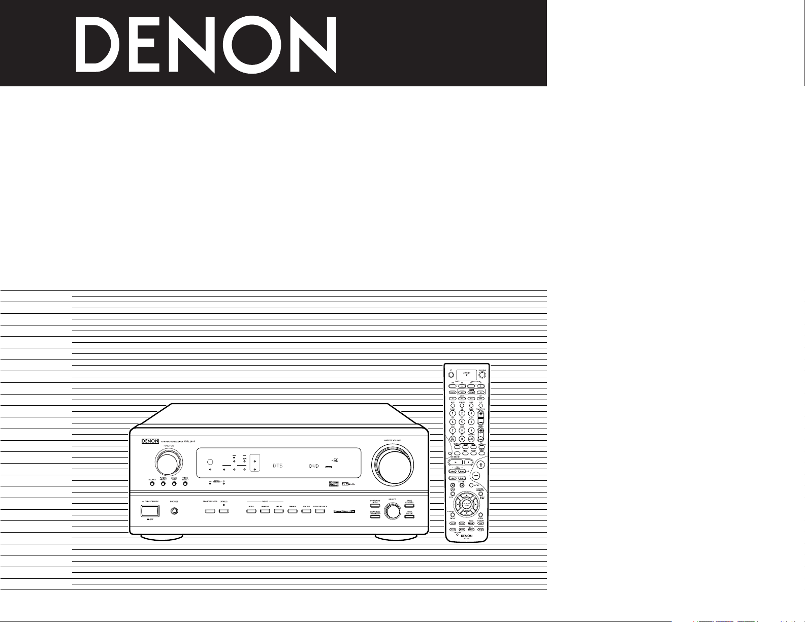
AV SURROUND RECEIVER
收音環繞擴音機
收音環繞擴音機
AVR-2803
OPERATING INSTRUCTIONS
操作說明書
操作說明書
OUTPUT
SIGNAL
DETECT
SURROUND
BACK CH
ON / STANDBY
REMOTE
SENSOR
AUTO
PCM
DTS
SIGNAL
DIGITAL
INPUT
VOLUME LEVEL
FOR ENGLISH READERS PAGE003 ~ PAGE044
中 文(繁體字版) 第 45 頁 ~ 第 186 頁
中 文(簡體字版) 第 87 頁 ~ 第 128 頁
Page 2
2
CAUTION:
TO REDUCE THE RISK OF ELECTRIC SHOCK, DO NOT REMOVE COVER (OR BACK). NO USERSERVICEABLE PARTS INSIDE. REFER SERVICING TO QUALIFIED SERVICE PERSONNEL.
The lightning flash with arrowhead symbol, within an equilateral triangle, is intended to alert the
user to the presence of uninsulated “dangerous voltage” within the product’s enclosure that
may be of sufficient magnitude to constitute a risk of electric shock to persons.
The exclamation point within an equilateral triangle is intended to alert the user to the presence
of important operating and maintenance (servicing) instructions in the literature accompanying
the appliance.
注意:
為防電擊﹐請勿打開機蓋(或後蓋)。本機內部無可供使用者使用的部件。請委托有資格的技術人員
進行修理安裝。
警告:
為防止火災或電擊﹐請勿將本機暴露于雨中或潮濕的處所。
等邊三角形中有箭頭閃電標號的圖形表示警告使用者在產品內有導電體及高電壓﹐可能會對人體
造成很大的電擊危險。
等邊三角形中有感嘆號的圖形表示﹐欲警告使用者該設備在操作與保養(服務)方面應嚴格按
照所附設備說明書。
注意:
為防電擊,請勿打開機蓋(或後蓋)。本機內部無可供使用者使用的部件。請委托有資格的技術人員
進行修理安裝。
警告:
為防止火災或電擊,請勿將本機暴露于雨中或潮濕的處所。
等邊三角形中有箭頭閃電標號的圖形表示警告使用者在產品內有導電體及高電壓,可能會對人體
造成很大的電擊危險。
等邊三角形中有感嘆號的圖形表示,欲警告使用者該設備在操作與保養(服務)方面應嚴格按
照所附設備說明書。
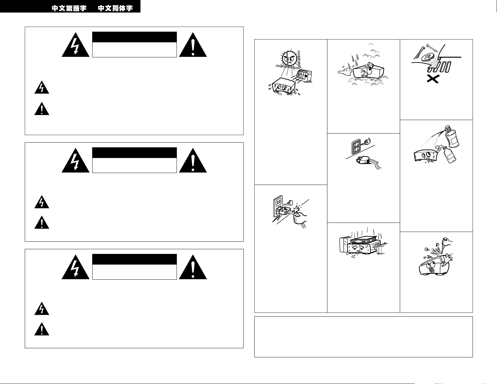
•Avoid high temperatures.
Allow for sufficient heat
dispersion when installed
on a rack.
• 防止高溫
裝於機架時應允許充分散
熱。
• 防止高溫
裝於機架時應允許充分散
熱。
• Handle the power cord
carefully.
Hold the plug when
unplugging the cord.
• 留意電源線
從插座撥出插頭時應該抓住
插頭將其撥出。
• 留意電源線
從插座撥出插頭時應該抓住
插頭將其撥出
。
• Keep the set free from
moisture, water, and dust.
• 勿將本機放置於濕度很高或
多塵的位置。
• 勿將本機放置於濕度很高或
多塵的位置。
• Unplug the power cord
when not using the set for
long periods of time.
• 長時間不使用本機時須將插
頭撥離電源插座。
• 長時間不使用本機時須將插
頭撥離電源插座。
* (For sets with ventilation holes)
*
(備有通風孔的機殼)
*
(備有通風孔的機殼)
• Do not obstruct the
ventilation holes.
• 勿堵塞機殼的通風孔。
• 勿堵塞機殼的通風孔。
• Do not let foreign objects
in the set.
• 勿讓雜物掉入機內。
• 勿讓雜物掉入機內。
• Do not let insecticides,
benzene, and thinner come
in contact with the set.
• 避免在本機附近噴灑殺蟲
劑,也勿用汽油,天拿水或
其它溶劑抹拭機箱。
• 避免在本機附近噴灑殺蟲
劑﹐也勿用汽油﹐天拿水或
其它溶劑抹拭機箱。
• Never disassemble or
modify the set in any way.
• 勿打開或隨意修理本機。
• 勿打開或隨意修理本機。
2 NOTE ON USE / 使用注意事項 / 使用注意事項
WARNING: TO REDUCE THE RISK OF FIRE OR ELECTRIC SHOCK, DO NOT
EXPOSE THIS APPLIANCE TO RAIN OR MOISTURE.
ENGLISH
CAUTION
• The ventilation should not be impeded by
covering the ventilation openings with items,
such as newspapers, table-cloths, curtains, etc.
• No naked flame sources, such as lighted candles,
should be placed on the apparatus.
• Please be care the environmental aspects of
battery disposal.
• The apparatus shall not be exposed to dripping or
splashing for use.
• No objects filled with liquids, such as vases, shall
be placed on the apparatus.
CAUTION
RISK OF ELECTRIC SHOCK
DO NOT OPEN
CAUTION
RISK OF ELECTRIC SHOCK
DO NOT OPEN
CAUTION
RISK OF ELECTRIC SHOCK
DO NOT OPEN
Page 3
3
ENGLISH
2 We greatly appreciate your purchase of the AVR-2803.
2 To be sure you take maximum advantage of all the features the AVR-2803 has to offer, read these
instructions carefully and use the set properly. Be sure to keep this manual for future reference,
should any questions or problems arise.
“SERIAL NO.
PLEASE RECORD UNIT SERIAL NUMBER ATTACHED TO THE REAR OF THE
CABINET FOR FUTURE REFERENCE”
2 INTRODUCTION
Thank you for choosing the DENON AVR-2803 Digital Surround AV receiver. This remarkable component has
been engineered to provide superb surround sound listening with home theater sources such as DVD, as well as
providing outstanding high fidelity reproduction of your favorite music sources.
As this product is provided with an immense array of features, we recommend that before you begin hookup and
operation that you review the contents of this manual before proceeding.
TABLE OF CONTENTS
z
Before Using........................................................3
x
Cautions on Installation........................................3
c
Cautions on Handling...........................................3
v
Features ...............................................................4
b
Connections.....................................................4~8
n
Part Names and Functions ..................................9
m
Setting up the System ................................10~17
,
Remote Control Unit ...................................18~22
.
Operation.....................................................23~27
⁄0
Surround ......................................................28~31
⁄1
DSP Surround Simulation ............................32~35
⁄2
Listening to the Radio..................................35, 36
⁄3
Last Function Memory.......................................37
⁄4
Initialization of the Microprocessor....................37
⁄5
Troubleshooting ...........................................37, 38
⁄6
Additional Information .................................38~43
⁄7
Specifications.....................................................44
2
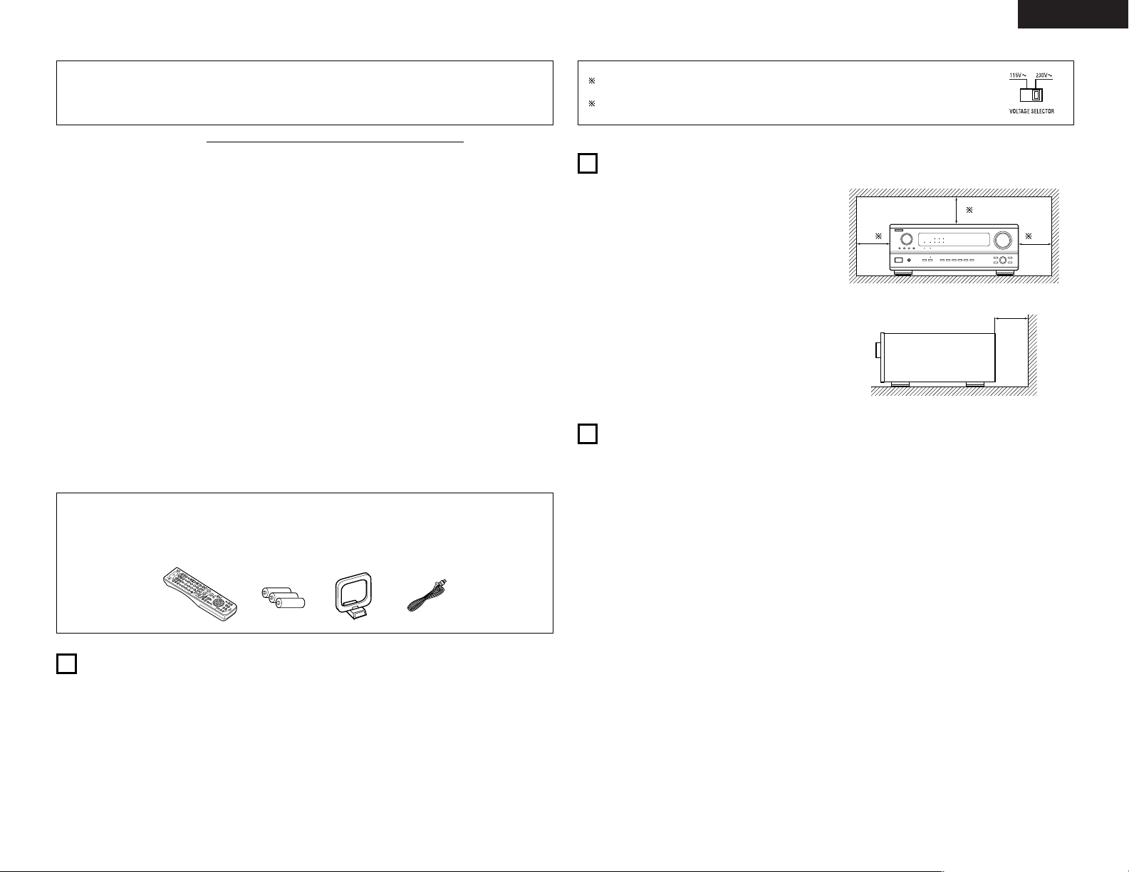
ACCESSORIES
Check that the following parts are included in addition to the main unit:
erty
q Operating instructions........................................1
w Service station list ..............................................1
e Remote control unit (RC-924) ............................1
r R6P/AA batteries................................................3
t AM loop antenna................................................1
y FM indoor antenna .............................................1
Noise or disturbance of the picture may be generated
if this unit or any other electronic equipment using
microprocessors is used near a tuner or TV.
If this happens, take the following steps:
• Install this unit as far as possible from the tuner or
TV.
• Set the antenna wires from the tuner or TV away
from this unit’s power cord and input/output
connection cords.
• Noise or disturbance tends to occur particularly
when using indoor antennas or 300 Ω/ohms feeder
wires. We recommend using outdoor antennas
and 75 Ω/ohms coaxial cables.
For heat dispersal, leave at least 10 cm of space
between the top, back and sides of this unit
and the wall or other components.
10 cm or more
wall
10 cm or more
2
CAUTIONS ON INSTALLATION
• Switching the input function when input jacks
are not connected
A clicking noise may be produced if the input
function is switched when nothing is connected to
the input jacks. If this happens, either turn down the
MASTER VOLUME control or connect components
to the input jacks.
• Muting of PRE OUT jacks, HEADPHONE jacks
and SPEAKER terminals
The PRE OUT jacks, HEADPHONE jack and
SPEAKER terminals include a muting circuit.
Because of this, the output signals are greatly
reduced for several seconds after the power switch
is turned on or input function, surround mode or any
other-set-up is changed. If the volume is turned up
during this time, the output will be very high after
the muting circuit stops functioning. Always wait
until the muting circuit turns off before adjusting the
volume.
• Whenever the power switch is in the
£ OFF
state, the apparatus is still connected on AC line
voltage.
Please be sure to unplug the cord when you
leave home for, say, a vacation.
3
CAUTIONS ON HANDLING
1
BEFORE USING
Pay attention to the following before using this unit:
• Moving the set
To prevent short circuits or damaged wires in the
connection cords, always unplug the power cord
and disconnect the connection cords between all
other audio components when moving the set.
• Before turning the power switch on
Check once again that all connections are proper
and that there are not problems with the connection
cords. Always set the power switch to the standby
position before connecting and disconnecting
connection cords.
• Store this instructions in a safe place.
After reading, store this instructions along with the
warranty in a safe place.
• Note that the illustrations in this instructions
may differ from the actual set for explanation
purposes.
• Line Voltage Selection (for multiple voltage model only)
The desired voltage may be set with the VOLTAGE SELECTOR knob on the rear panel,
using a screwdriver.
If the VOLTAGE SELECTOR knob does not move smoothly, please contact a qualified
serviceman.
B
Page 4
4
ENGLISH
• Do not plug in the AC cord until all connections
have been completed.
• Be sure to connect the left and right channels
properly (left with left, right with right).
• Insert the plugs securely. Incomplete connections
will result in the generation of noise.
• Use the AC OUTLETS for audio equipment
only. Do not use them for hair driers, etc.
• Note that binding pin plug cords together with AC
cords or placing them near a power transformer
will result in generating hum or other noise.
• Noise or humming may be generated if a
connected audio equipment is used independently
without turning the power of this unit on. If this
happens, turn on the power of the this unit
.
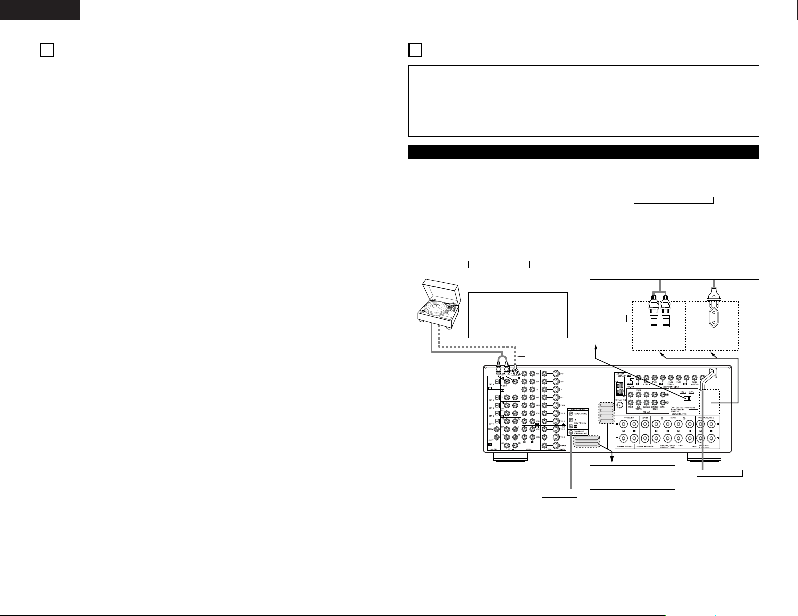
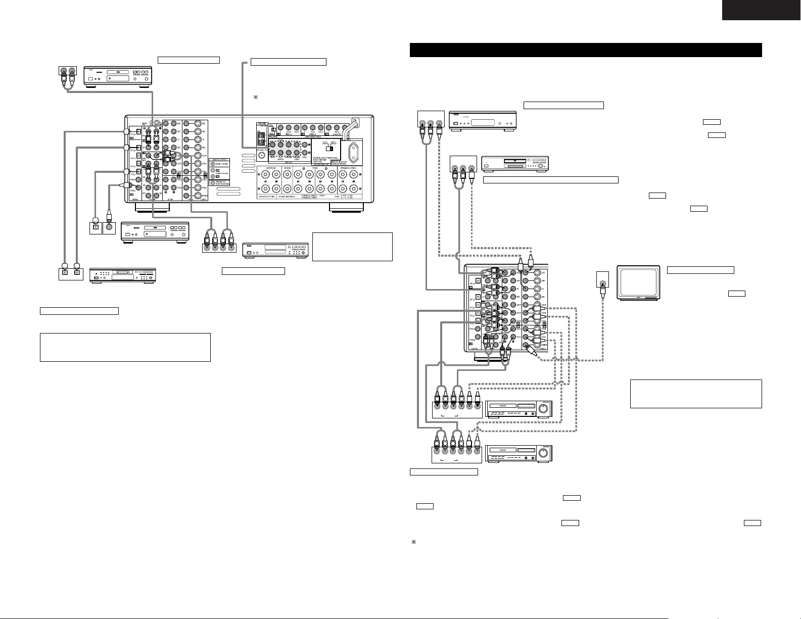
Connecting the audio components
5
CONNECTIONS
L
R
SAME AS LINE-VOLTAGE
SWITCHED 100W MAX.
AC OUTLET
SWITCHED TOTAL 120W MAX.
AC 120V 60Hz
AC OUTLETS
for Taiwan R.O.C. model
for Multiple voltage model
Connecting a Turntable
Connect the Turntable’s output cord to the
AVR-2803’s PHONO jacks, the L (left) plug to
the L jack, the R (right) plug to the right jack.
NOTES:
• This unit cannot be used with MC
cartridges directly. Use a separate head
amplifier or step-up transformer.
• If humming or other noise is generated
when the ground wire is connected,
disconnect the ground wire.
Turntable
(MM cartridge)
Ground wire
• When making connections, also refer to the operating instructions of the other components.
The power to these outlets is turned on and off when the power is switched between on and standby from
the remote control unit or power switch.
Power supply cord
AC 120 V, 60 Hz
(Taiwan R.O.C. model)
AC 115/230 V, 50/60 Hz
(Multiple voltage model)
TRIGGER OUT
Turn the DC 12V voltage on and off for the individual functions.
For details, see “Setting the Trigger Out Setup” on page 16.
Connecting the AC OUTLTETS
AC OUTLETS
• SWITCHED
(total capacity – 120 W – for Taiwan R.O.C. model)
(total capacity – 100 W – for Multiple voltage model)
The power to these outlets is turned on and off in conjunction with the
POWER operation switch on the main unit, and when the power is
switched between on and standby from the remote control unit.
No power is supplied from these outlets when this unit’s power is at
standby. Never connect equipment whose total capacity is above 120
W for Taiwan R.O.C. model (100 W for Multiple voltage model).
NOTE:
Only use the AC OUTLETS for audio equipment. Never use them for
hair driers, TVs or other electrical appliances.
Route the connection cords, etc., in
such a way that they do not
obstruct the ventilation holes.
VOLTAGE SELECTOR
For multiple voltage
model only
(Refer to page 3)
4
FEATURES
1. Digital Surround Sound Decoding
Featuring 32 bit high speed DSP, operating entirely
in digital domain, surround sound from digital
sources such as DVD, LD, DTV and satellite are
faithfully re-created.
2. DTS 96/24 compatibility
The AVR-2803 can be decoded with sources
recorded in DTS 96/24, a new multi-channel digital
signal format developed by Digital Theater
Systems Inc.
DTS 96/24 sources can be played in the multichannel mode on the AVR-2803 with high sound
quality of 96 kHz/24 bits or 88.2 kHz/24 bits.
3. DTS-ES Extended Surround and DTS Neo:6
The AVR-2803 is compatible with DTS-ES Extended
Surround, a new multi-channel format developed by
Digital Theater Systems Inc.
The AVR-2803 is also compatible with DTS Neo:6, a
surround mode allowing 6.1-channel playback of
regular stereo sources.
4. DTS (Digital Theater Systems)
DTS provides up to 5.1 channels of wide-range,
high fidelity surround sound, from sources such as
laser disc, DVD and specially-encoded music
discs.
5. Dolby Digital
Using advanced digital processing algorithms,
Dolby Digital provides up to 5.1 channels of widerange, high fidelity surround sound. Dolby Digital
is the default digital audio delivery system for DVD
and North American DTV.
6. Dolby Pro Logic II decoder
Dolby Pro Logic II is a new format for playing
multi-channel audio signals that offers
improvements over conventional Dolby Pro Logic.
It can be used to decode not only sources
recorded in Dolby Surround but also regular stereo
sources into five channels (front left/right, center
and surround left/right). In addition, various
parameters can be set according to the type of
source and the contents, so you can adjust the
sound field with greater precision.
7. Dolby Digital EX decoder system
Dolby Digital EX is a 6.1-channel surround format
proposed by Dolby Laboratories that allows users
to enjoy in their homes the “DOLBY DIGITAL
SURROUND EX” audio format jointly developed
by Dolby Laboratories and Lucas Films and first
used for the movie “Star Wars Episode 1 –
Phantom Menace”.
The 6.1 channels of sound, including surround
back channels, provide improved sound
positioning and expression of space.
8. Wide screen mode for a 7.1-channel sound
even with 5.1-channel sources
DENON has developed a wide screen mode with
a new design which recreates the effects of the
multi surround speakers in movie theaters. The
result is 7.1-channel sound taking full advantage of
surround back speakers, even with Dolby Pro
Logic or Dolby Digital/DTS 5.1-channel signals.
9. Multi Zone Music Entertainment System
Multi Source Function:
This unit’s Multi Source function lets you select
different audio sources for listening Different
sources can thus be enjoyed in the main room
(MAIN) and the subroom (ZONE 2)
simultaneously.
10. Component Video Switching
In addition to composite video and “S” video
switching, the AVR-2803 provides 2 sets of
component video (Y, P
B/CB
, PR/CR) inputs, and one
set of component video outputs to the television,
for superior picture quality.
11. Video Select Function
Allow you to watch one source (visual) while
listening to another source (audio).
12. Future Sound Format Upgrade Capability via
Eight Channel Inputs & Outputs
For future multi-channel audio format(s), the AVR2803 is provided with 7.1 channel (seven main
channels, plus one low frequency effects channel)
inputs, along with a full set of 7.1 channel pre-amp
outputs, controlled by the 8 channel master
volume control. This assures future upgrade
possibilities for any future multi-channel sound
format.
Page 5
5
ENGLISH
RLR
L
R
INPUT OUTPUT
LRL
R
OUTPUT
L
R
L
L
R
L
R
L
R
DIGITAL AUDIODIGITAL AUDIO
OUTPUT
OPTICAL COAXIAL
DIGITAL AUDIODIGITAL AUDIO
B
INPUT
OPTICAL
OUTPUT
B
CD player
Connecting a CD player
Connect the CD player’s analog
output jacks (ANALOG
OUTPUT) to this unit’s CD jacks
using pin plug cords.
Use these jacks if you wish to connect external power
amplifier(s) to increase the power of the front, center,
surround and surround back sound channels, or for
connection to powered loudspeakers.
To use Surround back with one speaker, connect the
speaker to SURR. BACK L CH.
MD recorder, CD recorder or other component
equipped with digital input/output jacks
CD player or other component equipped
with digital output jacks
Connecting the DIGITAL jacks
Use these for connections to audio equipment with digital output. Refer to
page 14 for instructions on setting this terminal.
Connecting a tape deck
Connections for recording:
Connect the tape deck’s recording input jacks (LINE IN or REC) to this unit’s
tape recording (CDR/TAPE OUT) jacks using pin plug cords.
Connections for playback:
Connect the tape deck’s playback output jacks (LINE OUT or PB) to this
unit’s tape playback (CDR/TAPE IN) jacks using pin plug cords.
CD recorder or Tape deck
NOTES:
• Use 75 Ω/ohms cable pin cords for coaxial connections.
• Use optical cables for optical connections, removing the cap before
connecting.
NOTE:
• If humming noise is generated
by a tape deck, etc., move the
tape deck away.
Connecting the pre-out jacks
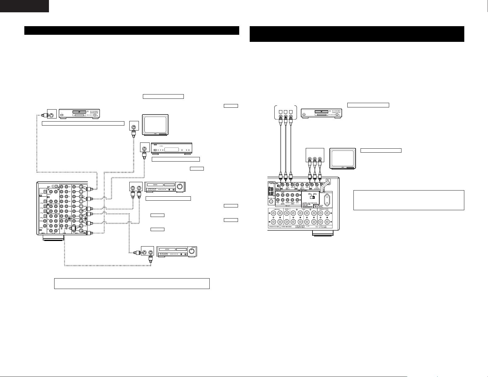
Connecting the video components
•To connect the video signal, connect using a 75 Ω/ohms video signal cable cord. Using an improper cable can
result in a drop in video quality.
• When making connections, also refer to the operating instructions of the other components.
IN
VIDEO
R
L
R OUT IN
AUDIO
VIDEO
OUT IN
LRL
RLR
L
R OUT IN
AUDIO
VIDEO
OUT IN
LRL
RLR
L
R OUT
VIDEO
OUT
L
AUDIO
L
R
R OUT
VIDEO
OUT
L
AUDIO
L
R
R
L
R
L
R
L
R L
B
B
RL
TV or DBS tuner
DVD player or video disc player (VDP), etc.
Monitor TV
Connecting a TV or DBS tuner
TV or DBS
• Connect the TV’s or DBS tuner’s video output jack (VIDEO OUTPUT) to the (yellow)
TV or DBS IN jack using a 75 Ω/ohms video coaxial pin plug cord.
• Connect the TV’s or DBS tuner’s audio output jacks (AUDIO OUTPUT) to the TV or
DBS IN jacks using pin plug cords.
AUDIO
VIDEO
Connecting a DVD player or a video disc player (VDP)
MONITOR OUT
• Connect the TV’s video input jack
(VIDEO INPUT) to the
MONITOR OUT jack using a 75
Ω/ohms video coaxial pin plug
cord.
VIDEO
Note on connecting the digital input jacks
• Only audio signals are input to the digital
input jacks. For details, see page 5.
Video deck 2
Video deck 1
• There are two sets of video deck (VCR) jacks, so two video decks can be connected for simultaneous recording or video copying.
Video input/output connections:
•Connect the video deck’s video output jack (VIDEO OUT) to the (yellow) VCR-1 IN jack, and the video deck’s video input jack (VIDEO IN) to the
(yellow) VCR-1 OUT jack using 75 Ω/ohms video coaxial pin plug cords.
Connecting the audio output jacks
• Connect the video deck’s audio output jacks (AUDIO OUT) to the VCR-1 IN jacks, and the video deck’s audio input jacks (AUDIO IN) to the
VCR-1 OUT jacks using pin plug cords.
Connect the second video deck to the VCR-2 jacks in the same way.
AUDIOAUDIO
VIDEO
VIDEO
Connecting a video decks
DVD
• Connect the DVD player’s video output jack (VIDEO OUTPUT) to the (yellow) DVD IN jack using a 75
Ω/ohms video coaxial pin plug cord.
• Connect the DVD player’s analog audio output jacks (ANALOG AUDIO OUTPUT) to the DVD IN jacks
using pin plug cords.
• VDP player can be connected to the VDP jacks in the same way.
• It is also possible to connect a video disc player, DVD player, video camcorder, video game machine, etc., to the
V.AUX jacks.
AUDIO
VIDEO
Connecting a monitor TV
Page 6
6
ENGLISH
IN
S-VIDEO
OUT
S-VIDEO
OUT
S-VIDEO
OUT IN
S-VIDEO
OUT IN
S-VIDEO
B
B
DVD player or video disc player (VDP)
Monitor TV
Video deck 2
Video deck 1
TV or satellite broadcast tuner
Connecting a DVD player or a video disc player (VDP)
Connecting a monitor TV
Connecting the video decks
Connecting a TV or DBS tuner
DVD
• Connect the DVD player’s S-Video output jack to the SVIDEO DVD IN jack using an S-Video connection cord.
•A VDP can be connected to the VDP jacks in the same way.
• It is also possible to connect a video disc player, DVD player,
video camcorder, game machine, etc., to the V.AUX jacks.
MONITOR OUT
• Connect the TV’s S video input (S-VIDEO INPUT) to the
MONITOR OUT jack using a S jack connection cord.
S-VIDEO
• Connect the TV’s or DBS tuner’s S video output jack (SVIDEO OUTPUT) to the TV or DBS IN jack using
an S-Video connection cord.
S-VIDEO
• Connect the video deck’s S output jack (S-OUT) to the
VCR-1 IN jack and the video deck’s S input jack (S-IN) to the
VCR-1 OUT jack using S-Video connection cords.
• Connect the video deck’s S output jack (S-OUT) to the
VCR-2 IN jack and the video deck’s S input jack (S-IN) to the
VCR-2 OUT jack using S-Video connection cords.
S-VIDEO
S-VIDEO
S-VIDEO
S-VIDEO
Connecting the video components equipped with S-Video jacks
• When making connections, also refer to the operating instructions of the other components.
• A note on the S input jacks
The input selectors for the S inputs and Video inputs work in conjunction with each other.
• Precaution when using S-jacks
This unit’s S-jacks (input and output) and video pin jacks (input and output) have independent circuit
structures, so that video signals input from the S-jacks are only output from the S-jack outputs and video
signals input from the pin jacks are only output from the pin jack outputs.
When connecting this unit with equipment that is equipped with S-jacks, keep the above point in mind and
make connections according to the equipment’s instruction manuals.
VIDEO OUT
Y
CRCB
COMPONENT
B
VIDEO IN
Y
CRCB
COMPONENT
DVD player
Monitor TV
Connecting a DVD player
Connecting a monitor TV
DVD IN jacks
• Connect the DVD player’s color difference (component) video output jacks
(COMPONENT VIDEO OUTPUT) to the COMPONENT VIDEO-1 IN jack using 75
Ω/ohms coaxial video pin-plug cords.
• In the same way, another video source with component video outputs such as
a TV or DBS tuner, etc., can be connected to the VIDEO-2 color difference
(component) video jacks.
MONITOR OUT jack
• Connect the TV’s color difference (component)
video input jacks (COMPONENT VIDEO INPUT)
to the COMPONENT MONITOR OUT jack using
75 Ω/ohms coaxial video pin-plug cords.
• The color difference input jacks may be indicated differently on some
TVs, monitors or video components (“CR, CB and Y”, “R-Y, B-Y and Y”,
“Pr, Pb and Y”, etc.). For details, carefully read the operating instructions
included with the TV or other component.
Connecting the Video Components equipped with Color Difference
(Component - Y, P
R/CR
, PB/CB) Video Jacks
• When making connections, also refer to the operating instructions of the other components.
• The signals input to the color difference (component) video jacks are not output to the VIDEO output jack
(yellow) or the S-Video output jack.
• Some video sources with component video outputs are labeled Y, C
B, CR, or Y, Pb, Pr, or Y, R-Y, B-Y. These
terms all refer to component video color difference output.
• The function assigned to the component video input can be changed at the system setup. For details, see
“Setting the Video In Assignment” on page 14.
• The AVR-2803’s on-screen display signals are not output from the color difference (component) video output
jacks (MONITOR OUT).
Connect the components’ audio inputs and outputs as described on page 5.
Page 7
7
ENGLISH
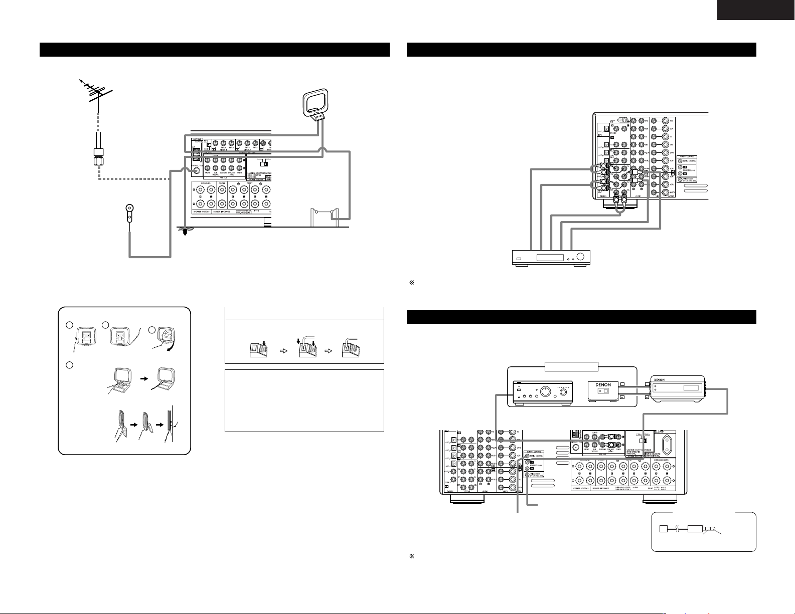
Connecting the antenna terminals
DIRECTION OF
BROADCASTING
STATION
75 Ω/ohms
COAXIAL
CABLE
FM ANTENNA
FM INDOOR
ANTENNA
(Supplied)
AM LOOP
ANTENNA
(Supplied)
AM OUTDOOR
ANTENNA
GROUND
• An F-type FM antenna cable plug can be connected directly.
1
4
2
3
AM loop antenna assembly
Connect to the AM
antenna terminals.
Remove the vinyl tie
and take out the
connection line.
Bend in the reverse
direction.
a. With the
antenna on
top any
stable
surface.
b. With the
antenna
attached to
a wall.
Mount
Installation hole Mount on wall, etc.
Connection of AM antennas
1. Push the
lever.
2. Insert the
conductor.
3. Return the
lever.
NOTES:
• Do not connect two FM antennas
simultaneously.
• Even if an external AM antenna is used, do
not disconnect the AM loop antenna.
• Make sure AM loop antenna lead terminals
do not touch metal parts of the panel.
L
R
L
R
RL
Decoder with 8- or 6-channel
analog output
Front
Surround back
Surround
Subwoofer
Center
For instructions on playback using the external input (EXT. IN) jacks, see page 24.
Connecting the external input (EXT. IN) jacks
• These jacks are for inputting multi-channel audio signals from an outboard decoder, or a component with a
different type of multi-channel decoder, such as a DVD Audio player, or a multi-channel SACD player, or other
future multi-channel sound format decoder.
• When making connections, also refer to the operating instructions of the other components.
L
R
++
OUTPUT
INPUT
AUX OUT
B
ZONE 2
Integrated pre-main amplifier or power amplifier
For instructions on operations using the ZONE 2 jacks, see pages 26, 27.
Connecting the ZONE 2 jacks
• If another pre-main (integrated) amplifier or power amplifier is connected, the ZONE 2 jacks can be used to
play a different program source in ZONE 2 at the same time.
RS232C GND
∆
3.5
STEREO PLUG
RXD
(PC IN)
TXD
(PC OUT)
Serial Control cable
Extension jacks for future use.
SERIAL CONTROL terminal
• Connect when using an external controller.
• Use an adapter cable (sold separately) as shown on the
diagram at the right to connect the external controller.
Page 8
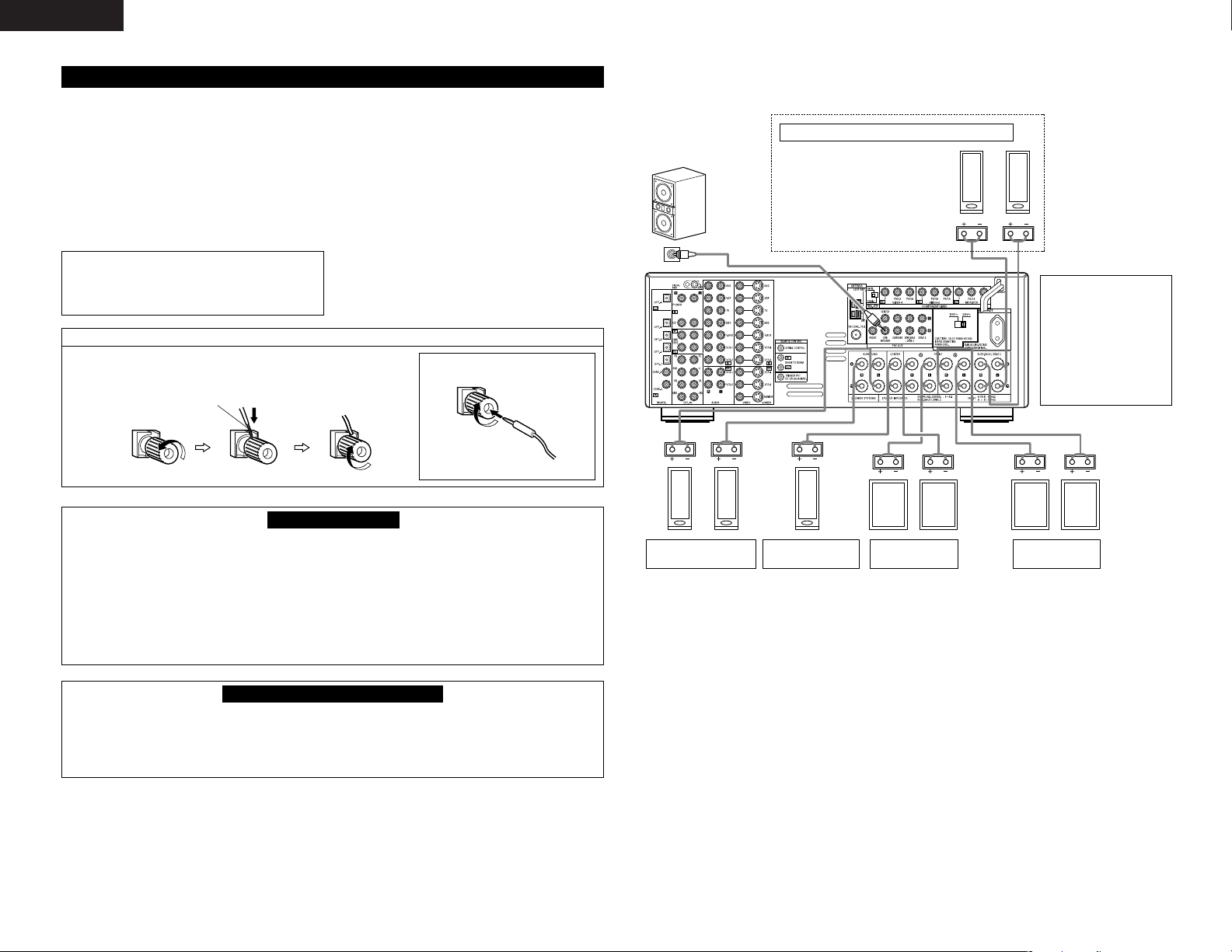
8
ENGLISH
Speaker Impedance
• Speakers with an impedance of from 6 to 16
Ω/ohms can be connected for use as front and
center speakers.
• Speakers with an impedance of 6 to 16 Ω/ohms
can be connected for use as surround and surround
back speakers.
• Be careful when using two pairs of front speakers
(A + B) at the same time, since use of speakers
with an impedance of less than 8 Ω/ohms will lead
to damage.
• The protector circuit may be activated if the set is
played for long periods of time at high volumes
when speakers with an impedance lower than the
specified impedance are connected.
NOTE:
NEVER touch the speaker terminals when the
power is on.
Doing so could result in electric shocks.
Connecting the speaker cords
1. Loosen by turning
counterclockwise.
2. Insert the cord. 3. Tighten by turning
clockwise.
Speaker system connections
• Connect the speaker terminals with the speakers
making sure that like polarities are matched ( <
with < , > with > ). Mismatching of polarities will
result in weak central sound, unclear orientation of
the various instruments, and the sense of direction
of the stereo being impaired.
• When making connections, take care that none of
the individual conductors of the speaker cord come
in contact with adjacent terminals, with other
speaker cord conductors, or with the rear panel.
Protector circuit
• This unit is equipped with a high-speed protection circuit. The purpose of this circuit is to protect the
speakers under circumstances such as when the output of the power amplifier is inadvertently shortcircuited and a large current flows, when the temperature surrounding the unit becomes unusually high, or
when the unit is used at high output over a long period which results in an extreme temperature rise.
When the protection circuit is activated, the speaker output is cut off and the power supply indicator LED
flashes. Should this occur, please follow these steps: be sure to switch off the power of this unit, check
whether there are any faults with the wiring of the speaker cables or input cables, and wait for the unit to
cool down if it is very hot. Improve the ventilation condition around the unit and switch the power back on.
If the protection circuit is activated again even though there are no problems with the wiring or the
ventilation around the unit, switch off the power and contact a DENON service center.
Note on speaker impedance
• The protector circuit may be activated if the set is played for long periods of time at high volumes when
speakers with an impedance lower than the specified impedance (for example speakers with an
impedance of lower than 4 Ω/ohms) are connected. If the protector circuit is activated, the speaker output
is cut off. Turn off the set’s power, wait for the set to cool down, improve the ventilation around the set,
then turn the power back on.
Either tightly twist or terminate the core wires.
Connecting banana plugs
(Taiwan R. O. C. model only)
banana plug
Turn clockwise to
tighten, then insert the
banana plug.
Connections
• When making connections, also refer to the operating instructions of the other components.
(L) (R)
(L) (R)
(L) (R) (L) (R)
Connection jack for
subwoofer with built-in
amplifier (super woofer),
etc.
CENTER SPEAKER
SYSTEM
FRONT SPEAKER
SYSTEMS (A)
•Precautions when
connecting speakers
If a speaker is placed near
a TV or video monitor, the
colors on the screen may
be disturbed by the
speaker’s magnetism. If
this should happen, move
the speaker away to a
position where it does not
have this effect.
SURROUND SPEAKER
SYSTEMS
SURROUND BACK/ZONE 2 SPEAKER SYSTEMS
NOTES:
•To use Surround back with one
speaker, connect the speaker to
SURR. BACK L CH.
• The settings must be changed to
use this speaker for ZONE 2.
See page 15.
FRONT SPEAKER
SYSTEMS (B)
Page 9
9
ENGLISH
OUTPUT
SIGNAL
DETECT
SURROUND
BACK CH
ON / STANDBY
REMOTE
SENSOR
AUTO
PCM
DTS
SIGNAL
DIGITAL
INPUT
VOLUME LEVEL
!7
!8!9@0@1@2@3@4@5@6@7@8
q w ter y u i
o!0 !1 !2 !3 !4 !5 !6
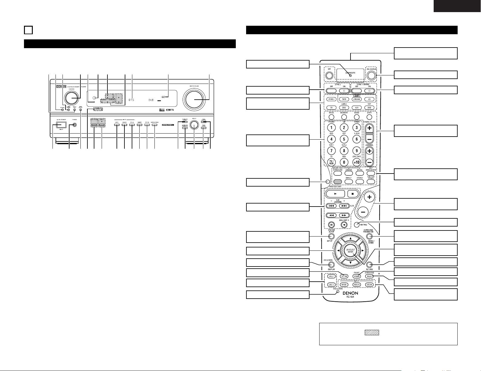
Front Panel
6
PART NAMES AND FUNCTIONS
• For details on the functions of these parts, refer to the pages given in parentheses ( ).
q
Power operation switch ...........................(23, 37)
w
Headphones jack (PHONES) ..........................(25)
e
VIDEO SELECT button ...................................(25)
r
Front speaker system indicators
(FRONT SPEAKER A/B)
t
FRONT SPEAKER button .........................(23, 37)
y
ZONE 2 button/indicator...........................(26, 37)
u
MODE button.....................................(23, 24, 30)
i
ANALOG button .......................................(23, 24)
o
EXT. IN button..........................................(23, 24)
!0
DIMMER button .............................................(26)
!1
STATUS button ...............................................(26)
!2
SURROUND BACK button .............................(30)
!3
SURROUND MODE button .........(24, 28~30, 33)
!4
SURROUND PARAMETER
button.................................................(29~31, 33)
!5
SELECT knob...................(24, 25, 28~31, 33, 34)
!6
TONE DEFEAT button....................................(25)
!7
TONE CONTROL button ..........................(25, 34)
!8
MASTER VOLUME control ............................(24)
!9
Master volume indicator (VOLUME LEVEL) ..(24)
@0
Display
@1
INPUT mode indicators ..................................(24)
@2
SIGNAL indicators ..........................................(24)
@3
Remote control sensor
(REMOTE SENSOR) .......................................(18)
@4
Power indicator ..............................................(23)
@5
FUNCTION knob ..............(23, 25, 26, 30, 35, 36)
@6
TUNING PRESET button ................................(36)
@7
SOURCE selector button ...............................(23)
@8
ZONE 2/REC button .......................................(26)
Remote control unit
• For details on the functions of these parts, refer to the pages given in parentheses ( ).
SYSTEM CALL buttons................(21)
ON SCREEN/DISPLAY button
.(19, 20, 26)
Cursor buttons .............................(10)
TEST TONE button ......................(28)
System buttons .....................(18~22)
ZONE 2 buttons ...........................(27)
MODE SELECT button ................(18)
Input source selector
buttons ..........(19, 20, 23, 27, 30, 35)
SYSTEM SETUP/SETUP
button ........................(10, 11, 17, 19)
Mode selector
buttons ............................(18~23, 27)
Surround buttons
............................(23, 25, 28~30, 32)
ZONE 1/MAIN buttons.................(27)
Power buttons .......................(19~23)
Tuner system/System
buttons ................(18, 20, 27, 35, 36)
MUTING button ...........................(25)
Master volume control
buttons...................................(24, 27)
RETURN button .....................(19, 20)
Remote control signal
transmitter ...................................(18)
INPUT MODE selector
buttons...................................(23, 24)
SURROUND PARAMETER
button ..................(19, 20, 29, 31~33)
CH SELECT/ENTER button
...................................(10, 19, 20, 28)
SURROUND BACK button...........(30)
LED (indicator)..............................(20)
USE/LEARN button................(20, 22)
FRONT SPEAKER button.............(23)
NOTE:
• The shaded button does not function with the AVR-2803.
(Nothing happens when they are pressed.)
Page 10
10
ENGLISH
SYSTEM SETUP button
Press this to display the system setup menu.
ENTER button
Press this to switch the display.
Also use this button to complete the setting.
CURSOR buttons
0
and 1: Use these to move the cursors (0and 1) to
the left and right on the screen.
• and ª: Use these to move the cursors (• and ª) to
the up and down on the screen.
NOTES:
• The on-screen display signals are output with priority to the S-VIDEO MONITOR OUT jack during playback
of a video component. For example, if the TV monitor is connected to both the AVR-2803’s S-Video and
video monitor output jacks and signals are input to the AVR-2803 from a video source (VDP, etc.) connected
to both the S-Video and video input jacks, the on-screen display signals are output with priority to the SVideo monitor output. If you wish to output the signals to the video monitor output jack, do not connect a
cord to the S-VIDEO MONITOR OUT jack. (For details, see page 17.)
• The AVR-2803’s on-screen display function is designed for use with high resolution monitor TVs, so it may
be difficult to read small characters on TVs with small screens or low resolutions.
• The setup menu is not displayed when headphones are being used.
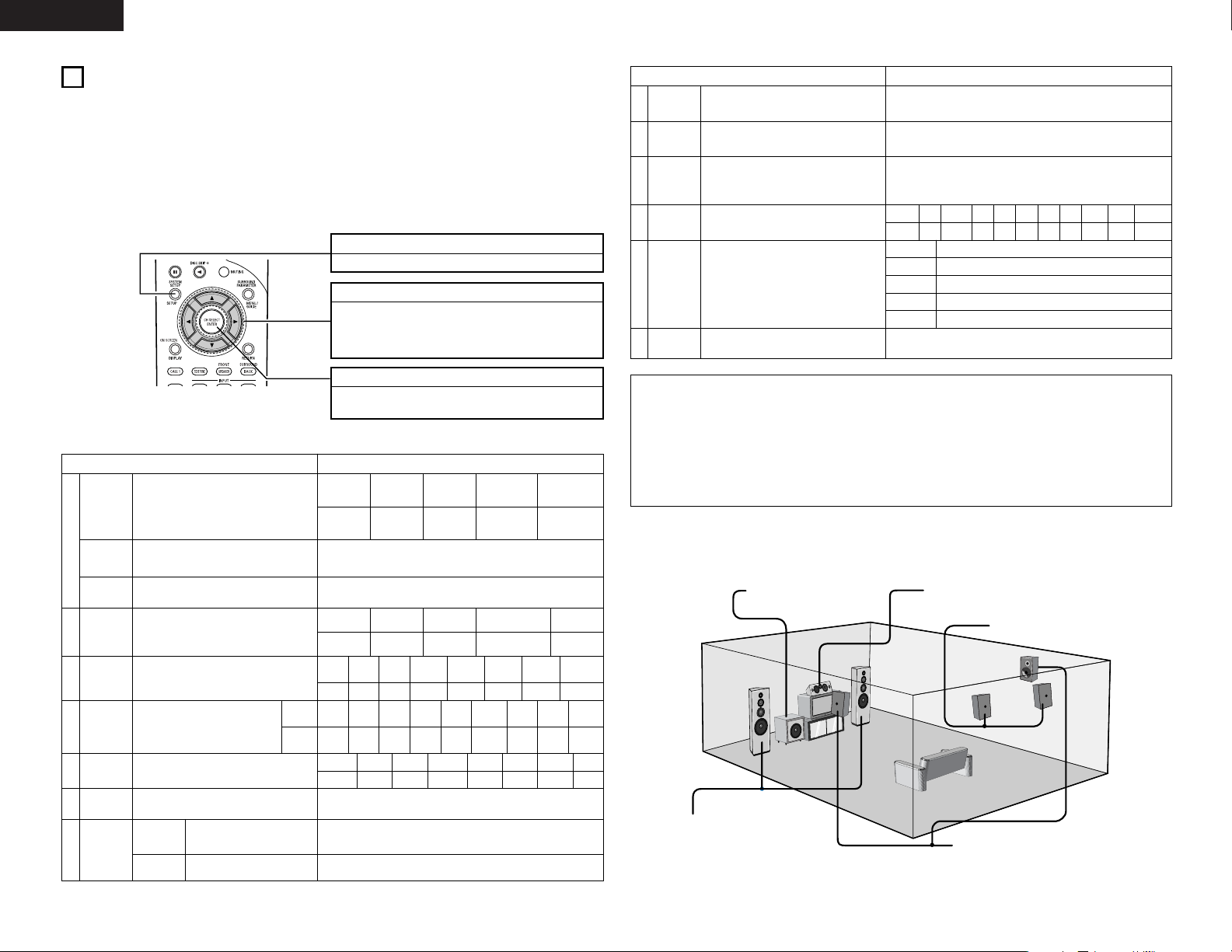
• Speaker system layout
Basic system layout
• The following is an example of the basic layout for a system consisting of eight speaker systems and a
television monitor:
Subwoofer Center speaker system
Surround speaker systems
Surround back speaker systems
Front speaker systems
Set these at the sides of the TV or
screen with their front surfaces as flush
with the front of the screen as possible.
7
SETTING UP THE SYSTEM
• Once all connections with other AV components have been completed as described in “CONNECTIONS”
(see pages 4 to 8), make the various settings described below on the monitor screen using the AVR-2803’s
on-screen display function.
These settings are required to set up the listening room’s AV system centered around the AVR-2803.
• Check that the remote control unit is set to AMP mode (TAPE, CDR/MD or CD).
• The system settings can be reset to the default (factory shipment) settings by initialization of the
microprocessor (see page 37).
• Use the following buttons to set up the system:
• System setup items and default values (set upon shipment from the factory)
System setup Default settings
y
e
r
Speaker
Configuration
Subwoofer
mode
Dolby Digital
Setup
Channel
Level
Digital In
Assignment
Input the combination of speakers in your
system and their corresponding sizes (Small for
regular speakers, Large for full-size, full-range) to
automatically set the composition of the signals
output from the speakers and the frequency
response.
This selects the subwoofer speaker for playing
deep bass signals.
Turn the audio compression on or off when downmixing Dolby Digital signals.
This adjusts the volume of the signals output from
the speakers and subwoofer for the different
channels in order to obtain optimum effects.
This assigns the digital input jacks for the
different input sources.
Input
source
Digital
Inputs
Front Sp.
Large
Center Sp. Surround Sp.Sub Woofer
Small SmallYes
LFE
Front L & R Center Surround L & RSub Woofer
3.6 m (12 ft) 3.6 m (12 ft) 3.0 m (10 ft)3.6 m (12 ft)
Front L
Front R Center
Surround
R
Surround
Back R
Subwoofer
0 dB 0 dB 0 dB 0 dB 0 dB 0 dB
CD
DVD VDP TV DBS TAPE
COAX1 COAX2 OPT1 OPT2 OPT3 OPT4
Surround Back
Sp.
Small / 2spkrs
OFF
w
Delay Time
This parameter is for optimizing the timing with
which the audio signals are produced from the
speakers and subwoofer according to the listening
position.
SBL & SBR
3.0 m (10 ft)
Surround
Back L
0 dB
Surround
L
0 dB
VCR-1
OFF
V. AUX
OFF
q
Crossover
Frequency
Set the frequency (Hz) below which the bass sound
of the various speakers is to be output from the
subwoofer.
80 Hz
VCR-2
OFF
t
Video In
Assignment
This assigns the color difference (component)
video input jacks for the different input sources.
DVD
VDP TV VCR-1 V. AUX
—
VIDEO1 NONE NONE NONE NONE
—
VCR-2
NONE
DBS
VIDEO2
Set this to switch the surround back
channel’s power amplifier for use
for zone 2.
Surround Back
Power AMP
Assignment
This sets the output level for the
zone 2 output jacks.
Variable
Zone2 vol.
Level
u
Zone2
Control
System setup Default settings
!1
On Screen
Display
This sets whether or not to display the on-screen
display that appears on the monitor screen when
the controls on the remote control unit or main unit
are operated.
On Screen Display = ON
A1 ~ A8 87.5 / 89.1 / 98.1 / 108.0 / 90.1 / 90.1 / 90.1 / 90.1 MHz
B1 ~ B8 522 / 603 / 999 / 1404 / 1611 kHz, 90.1 / 90.1 MHz
C1 ~ C8 90.1 MHz
D1 ~ D8 90.1 MHz
E1 ~ E8 90.1 MHz
!3
Auto Tuner
Preset
FM stations are received automatically and stored
in the memory.
i
o
Ext. In
Subwoofer
Level
Set the Ext. In Subwoofer terminal playback level. Subwoofer = +15 dB
!0
Auto
Surround
Mode
Set the Auto surround mode function. Auto Surround Mode = ON
!2
Trigger Out
Setup
Set the Trigger Out output for the different input
sources.
PHONO
CD TUNER DVD TVVDP
TAPE
DBS VCR-1
OFF OFF OFF
ON ONON
OFF
ON ON
Setup Lock
Set whether or not to lock the system setup
settings so that they cannot be changed.
Setup Lock = OFF
VCR-2
ON
V. AUX
ON
Page 11
11
ENGLISH
• Set up in function of your speaker systems. Performing this setup optimizes the system.
• The composition of the signals output to the different channels and the frequency response are adjusted
automatically according to the combination of speakers actually being used.
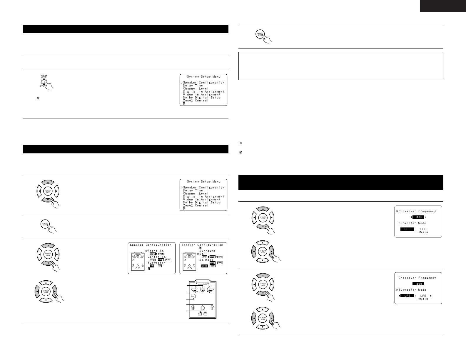
Setting the type of speakers
1
At the System Setup Menu select “Speaker Configuration”.
2
Switch to the speaker configuration screen.
Center Sp.
Front Sp.
Subwoofer
Surround Sp.
Surround back Sp.
NOTE:
• Select “Large” or “Small” not according to the actual size of the speaker but according to the speaker’s
capacity for playing low frequency (bass sound below frequency set for the Crossover Frequency mode and
below) signals. If you do not know, try comparing the sound at both settings (setting the volume to a level
low enough so as not to damage the speakers) to determine the proper setting.
3
Set whether or not speakers
are connected and, if so, their
size parameters.
•To select the speaker
•To select the parameter
4
Press the ENTER button to finalize the setting.
• Parameters
Large.................Select this when using speakers that have sufficient performance for reproducing bass
sound below the frequency set for the Crossover Frequency mode.
Small .................Select this when using speakers that do not have sufficient performance for reproducing
bass sound below the frequency set for the Crossover Frequency mode. When this is set,
bass sound with a frequency below the frequency set for the Crossover Frequency mode
is sent to the subwoofer.
When this setting is selected, low frequencies of below the frequency set for the Crossover
Frequency mode are assigned to the subwoofer.
None…… ..........Select this when no speakers are installed.
Yes/No… ...........Select “Yes” when a subwoofer is installed, “No” when a subwoofer is not installed.
2spkrs/1spkr .....Set the number of speakers to be used for the surround back channel.
If the subwoofer has sufficient low frequency playback capacity, good sound can be achieved even when
“Small” is set for the front, center and surround speakers.
For the majority of speaker system configurations, using the Small setting for all five main speakers and
Subwoofer On with a connected subwoofer will yield the best results.
• Before setting up, connect the AVR-2803’s MONITOR OUT connector with the monitor TV and turn off the
power of all playback devices connected to the AVR-2803’s video input connectors. (For instructions on
connecting the monitor TV, see page 5 and 6.)
Before setting up the system
2
Display the System Setup Menu.
1
Check that all the connections are correct, then turn on the main unit’s power.
To stop system setup before it is completed, press the system setup
button again.
System setup can be stopped at any time.
The changed settings are stored and the on-screen display turns off.
• If you make a mistake at a system setup setting, you can reset it by selecting the desired menu from the
System Setup Menu screen.
Setting the crossover frequency and low frequency distribution when
playing Dolby Digital and DTS signals
1
Select the “Crossover Frequency” mode.
• Set the crossover frequency and subwoofer mode according to the speaker system being used.
Select the Frequency.
2
Select the “Subwoofer Mode”.
Select the setting.
Page 12
12
ENGLISH
3
Enter the setting.
The System Setup Menu reappears.
NOTES:
— Assignment of low frequency signal range —
• The only signals produced from the subwoofer channel are LFE signals (during playback of Dolby Digital or
DTS signals) and the low frequency signal range of channels set to “Small” in the setup menu. The low
frequency signal range of channels set to “Large” are produced from those channels.
— Crossover Frequency —
• When “Subwoofer” is set to “Yes” at the “Speaker Configuration Setting”, set the frequency (Hz) below
which the bass sound of the various speakers is to be output from the subwoofer (the crossover
frequency).
• For speakers set to “Small”, sound with a frequency below the crossover frequency is cut, and the cut bass
sound is output from the subwoofer instead.
NOTE: For ordinary speaker systems, we recommend setting the crossover frequency to 80 Hz. When
using small speakers, however, setting the crossover frequency to a high frequency may improve
frequency response for frequencies near the crossover frequency.
— Subwoofer mode —
• The subwoofer mode setting is only valid when “Large” is set for the front speakers and “Yes” is set for
the subwoofer in the “Speaker Configuration” settings (see page 11).
• When the “LFE+MAIN” playback mode is selected, the low frequency signal range of channels set to
“Large” are produced simultaneously from those channels and the subwoofer channel.
In this playback mode, the low frequency range expand more uniformly through the room, but depending
on the size and shape of the room, interference may result in a decrease of the actual volume of the low
frequency range.
• Selection of the “LFE ” play mode will play the low frequency signal range of the channel selected with
“Large” from that channel only. Therefore, the low frequency signal range that are played from the
subwoofer channel are only the low frequency signal range of LFE (only during Dolby Digital or DTS signal
playback) and the channel specified as “Small” in the setup menu.
• Select the play mode that provides bass reproduction with quantity.
• When the subwoofer is set to “Yes”, bass sound is output from the subwoofer regardless of the subwoofer
mode setting in surround modes other than Dolby/DTS.
• In surround modes other than Dolby Digital and DTS, if the subwoofer is set to “YES”, the low frequency
portion is always output to the subwoofer channel. For details, refer to “Surround Modes and Parameters”
on page 34, 35.
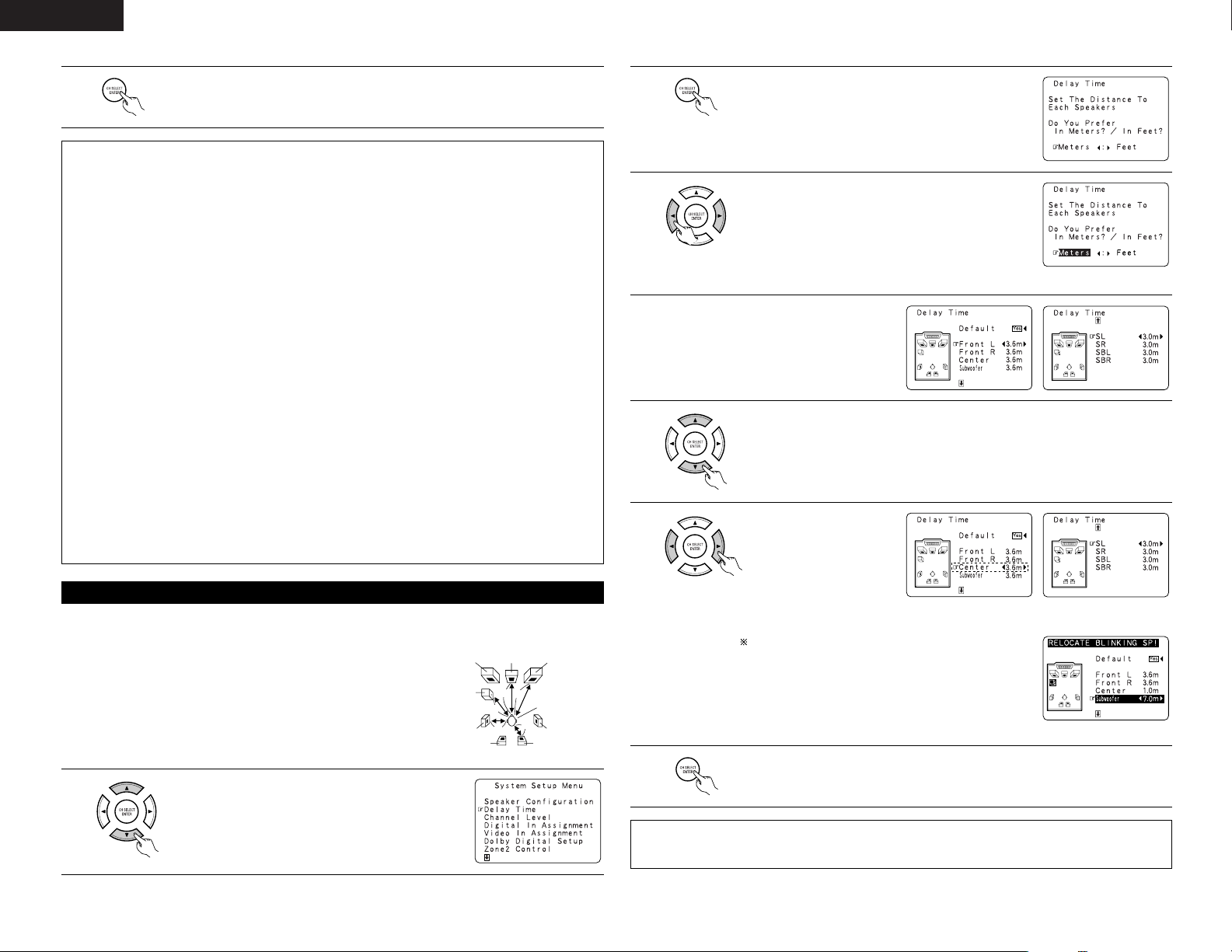
• Input the distance between the listening position and the different speakers to set the delay time for the
surround mode.
Setting the delay time
Preparations:
Measure the distances between the listening position and the speakers
(L1 to L5 on the diagram at the right).
L1: Distance between center speaker and listening position
L2: Distance between front speakers and listening position
L3: Distance between surround speakers and listening position
L4: Distance between surround back speakers and listening position
L5: Distance between subwoofer and listening position
L1
L2
L5
L3
L4
Center FRFL
Subwoofer
SL
Listening position
SR
SBRSBL
1
At the System Setup Menu select “Delay Time”.
2
Switch to the Delay Time screen.
Example: When “Meters” is selected
3
Select the desired unit, meters or feet.
Select (darken) the desired units, “Meters” or “Feet”.
4
Once “Meter” or “Feet” is selected in Step 3,
the Delay Time screen appears automatically.
5
Select the speaker to be set.
Example: When the distance is set to
3.6 m for the center speaker
6
Set the distance between
the center speaker and
listening position.
The distance changes in
units of 0.1 meters (1 foot)
each time the button is
pressed. Select the value
closest to the measured
distance.
If “Yes” is selected for “Default”, the settings are
automatically reset to the default values.
Please note that the difference of distance for every speaker
should be 6.0 m (20 ft) or less. If you set an invalid distance,
a CAUTION notice, such as screen right will appear. In this
case, please relocate the blinking speaker(s) so that its
distance is no larger than the value shown in highlighted line.
7
Enter the setting.
The System Setup Menu reappears.
The AVR-2803 automatically sets the optimum surround delay time for the listening room.
NOTES:
• If the distance unit is changed after the delay time is set, the settings are reset to the factory default values
(see pages 10).
Page 13
13
ENGLISH
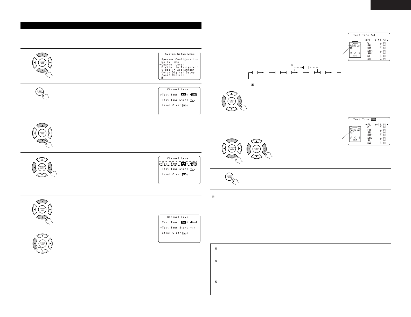
• Use this setting to adjust so that the playback level between the different channels is equal.
•From the listening position, listen to the test tones produced from the speakers to adjust the level.
• The level can also be adjusted directly from the remote control unit. (For details, see page 28.)
Setting the channel level
1
At the System Setup Menu select “Channel Level”.
2
Switch to the Channel Level screen.
3
Select “Test Tone”.
Example: When the “Auto” mode is selected
4
Select the mode.
Select “Auto” or “Manual”.
•Auto:
Adjust the level while listening to the test tones
produced automatically from the different speakers.
• Manual:
Select the speaker from which you want to produce the
test tone to adjust the level.
5
Select “Test Tone Start”.
Use the CURSOR left and right buttons to adjust all the speakers to the same volume.
The volume can be adjusted between –12 dB and +12 dB in units of 0.5 dB.
Example: When the volume is set to
–11.5 dB while the test
tone is being produced
from the Front L-ch speaker
FL C FR SR SBR SBL SL SW
SB
1spkr
2spkrs
When the surround back speaker setting is set to “1spkr” for “Speaker
Configuration”, this is set to “SB”.
6
Select “Yes”.
7
a. If the “Auto” mode is selected:
Test tones are automatically emitted from the different
speakers.
The test tones are emitted from the different speakers in
the following order, at 4-second intervals the first time and
second time around, 2-second intervals the third time
around and on:
Flashing
Example: When the volume is set to
–11.5 dB while the Front Lch speaker is selected
b. When the “Manual” mode is selected
Use the CURSOR up and down to select the speaker for
which you want to output test tones, then use the
CURSOR left and right to adjust so that the volume of the
test tones from the various speakers is the same.
Flashing
8
After the above settings are completed, press the ENTER button.
The “Channel Level” screen reappears.
To cancel the settings, select “Level Clear” and “Yes” on the “Channel Level” screen, then make the
settings again.
The level of each channel should be adjusted to 75 dB (C-weighted, slow meter mode) on a sound level meter
at the listening position.
If a sound level meter is not available adjust the channels by ear so the sound levels are the same. Because
adjusting the subwoofer level test tone by ear is difficult, use a well known music selection and adjust for natural
balance.
NOTE: When adjusting the level of an active subwoofer system, you may also need to adjust the subwoofer’s
own volume control.
When you adjust the channel levels while in the SYSTEM SETUP CHANNEL LEVEL mode, the channel
level adjustments made will affect ALL surround modes. Consider this mode a Master Channel Level
adjustment mode.
After you have completed the SYSTEM SETUP CHANNEL LEVEL adjustments, you can then activate the
individual surround modes and adjust channel levels that will be remembered for each of those modes.
Then, whenever you activate a particular surround sound mode, your preferred channel level adjustments
for just that mode will be recalled. Check the instructions for adjusting channel levels within each
surround mode on page 28.
You can adjust the channel levels for each of the following surround modes: DIRECT, STEREO,
DOLBY/DTS SURROUND, 5/7 CH STEREO, MONO MOVIE, ROCK ARENA, JAZZ CLUB, VIDEO GAME,
MATRIX and VIRTUAL.
Page 14
14
ENGLISH
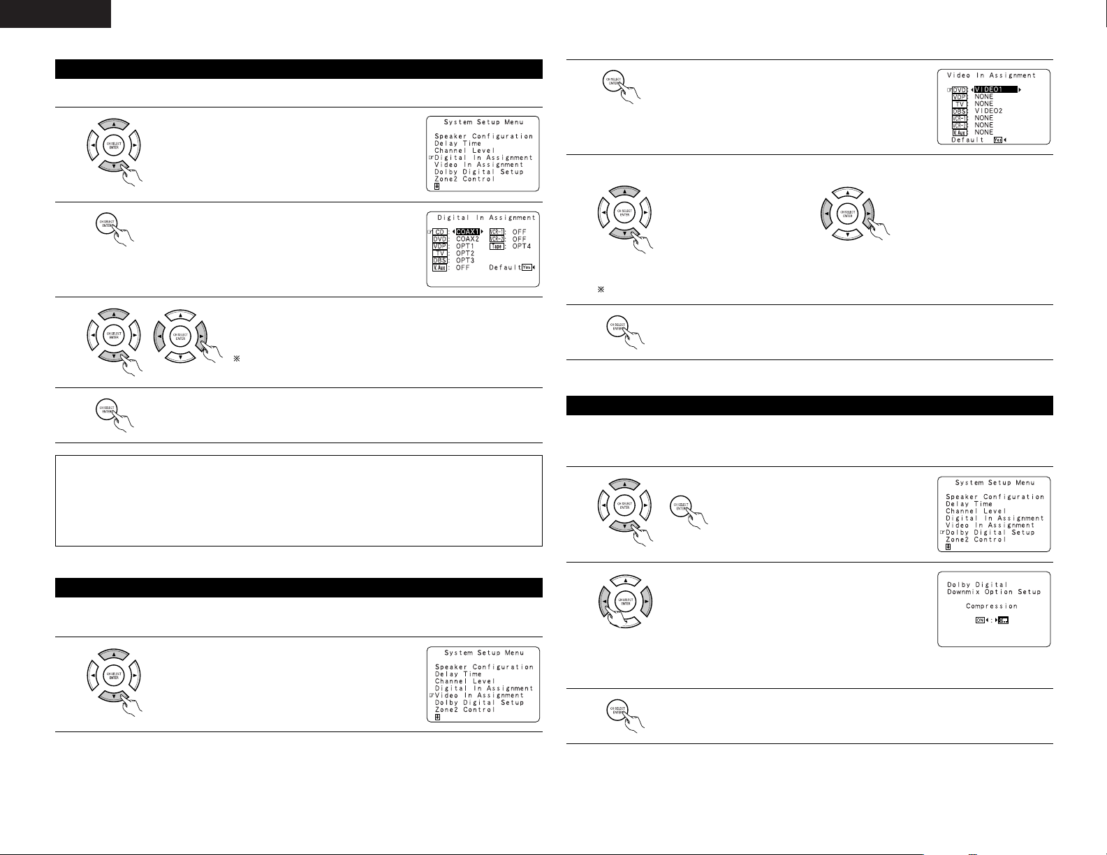
• This setting assigns the digital input jacks of the AVR-2803 for the different input sources.
Setting the Digital In Assignment
1
At the System Setup Menu select “Digital In Assignment”.
2
Switch to the Digital In Assignment screen.
3
Select the digital input jack to be assigned to the input source.
•To select the input source
•To select the digital input jack
Select “OFF” for input sources for which no digital input jacks are used.
If “Yes” is selected for “Default”, the settings are automatically
reset to the default values.
NOTES:
• The OPTICAL 4 jacks on the AVR-2803’s rear panel are equipped with an optical digital output jack for
recording digital signals on a CD recorder, MD recorder or other digital recorder. Use this for digital recording
between a digital audio source (stereo - 2 channel) and a digital audio recorder.
• Do not connect the output of the component connected to the OPTICAL 4 OUT jack on the AVR-2803’s rear
panel to any jack other than the OPTICAL 4 IN jack.
• “PHONO” and “TUNER” cannot be selected on the Digital In Assignment screen.
4
Enter the setting.
The System Setup Menu reappears.
• This setting assigns the color difference (component) video input jacks of the AVR-2803 for the different input
sources.
Setting the Video In Assignment
1
At the System Setup Menu select “Video In Assignment”.
3
Select the component (Y, PB/CB and PR/CR) video input terminal to be assigned to the input source.
q Input source selection w Component video terminal
selection
Select “NONE” for sources for which the component (Y, P
B/CB and PR/CR) video input is not to be used.
When the default, “Yes”, is selected, the settings are reset to the factory defaults.
4
ENTER the setting.
The System Setup Menu reappears.
2
Switch to the Video In Assignment screen.
Sets the down-mixing method when not using a center speaker or surround speakers.
OFF: The dynamic range is not compressed.
ON: The dynamic range is compressed automatically according to the combination of speakers being used.
Setting the Dolby Digital Setup
1
At the System Setup Menu select “Dolby
Digital Setup” and press the ENTER button.
2
Select “ON” if you want to use the Compression, “OFF”
if you do not want to use it.
3
Enter the setting.
The System Setup Menu reappears.
NOTE:
When not using a center speaker or surround speakers,
the sound is played from the front speakers. If the sound
should seem distorted because the input level exceeds the
allowable input for the front speakers, set “Compression”
to “ON”.
Page 15
15
ENGLISH
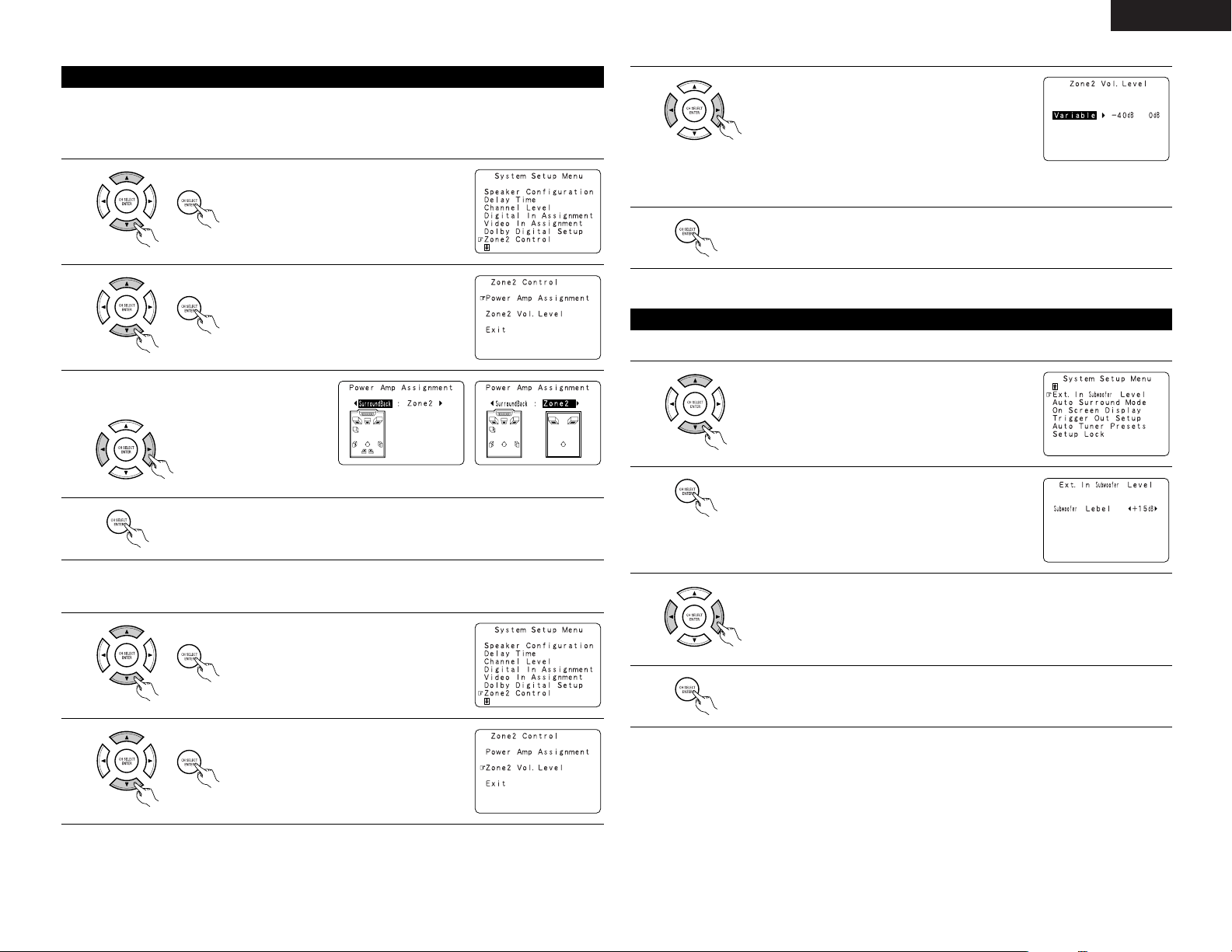
[1] Setting the power amplifier assignment
Make this setting to switch the power amplifier for the surround back channel to ZONE2.
If ZONE2 is selected, the signal that selected at ZONE2 is output at “SURR. BACK/ZONE2 PREOUT”
terminals.
Setting the ZONE2 Control
1
At the System Setup Menu select “Zone2
Control” and press the ENTER button.
2
The “Zone2 Control” screen appears.
Select “Power Amp Assignment” and press
the ENTER button.
3
Select “Surround Back” to use as the surround
back channel, “Zone2” to use as Zone 2 out.
4
Enter the setting.
At the “Zone2 Control” screen, select “Exit” and press the ENTER button.
The System Setup Menu reappears.
When “Zone2” is selectedWhen “Surround Back” is selected
[2] Setting the Zone2 vol. level
Set the Zone 2 pre-out output level adjustment.
1
At the System Setup Menu select “Zone2
Control” and press the ENTER button.
2
The “Zone2 Control” screen appears.
Select “Zone2 Vol. Level” and press the
ENTER button.
3
Select the desired setting.
Variable:
The level can be adjusted freely using the buttons on the
remote control unit.
0 dB, -40 dB:
The output level is fixed at the set level and the volume
can no longer be adjusted.
4
Enter the setting.
At the “Zone2 Control” screen, select “Exit” and press the ENTER button.
The System Setup Menu reappears.
• Set the method of playback of the analog input signal connected to the Ext.In Subwoofer.
Setting the Ext. In Subwoofer Level
1
At the System Setup Menu select “Ext.In Subwoofer Level”.
2
Switch to the Ext.In Subwoofer Level screen.
3
Select the desired setting.
Select according to the specifications of the player being used. Also refer to the player’s
operating instructions.
+15dB (default) recommended. (0, +5, +10 and +15 can be selected.)
4
Enter the setting.
The System Setup Menu reappears.
Page 16
16
ENGLISH
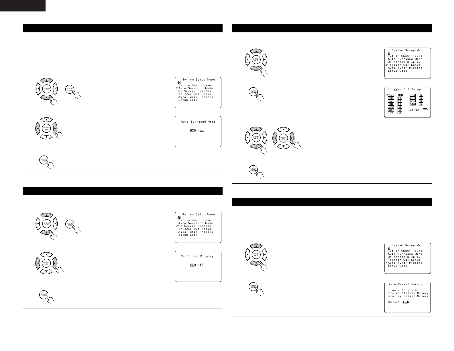
The surround mode used at last for the three types of input signals shown below is stored in the memory, and
the signal is automatically played with that surround mode the next time it is input.
Note that the surround mode setting is also stored separately for the different input sources.
q Analog and PCM 2-channel signals
w 2-channel signals of Dolby Digital, DTS or other multi-channel format
e Multi-channel signals of Dolby Digital, DTS or other multi-channel format
Setting the Auto Surround Mode
1
At the System Setup Menu select “Auto
Surround Mode” and press the ENTER button.
2
Select “ON” if you want to use the auto surround mode,
“OFF” if you do not want to use it.
3
Enter the setting.
The System Setup Menu reappears.
• Use this to turn the on-screen display (messages other than the menu screens) on or off.
Setting the on screen display (OSD)
1
At the System Setup Menu select “On Screen
Display” and press the ENTER button.
2
Select “ON” or “OFF”.
3
Enter the setting.
The System Setup Menu reappears.
• Sets the Trigger Out output for the different input sources.
Setting the Trigger Out Setup
1
At the System Setup Menu select “Trigger Out Setup”.
2
Switch to the Trigger Out Setup screen.
3
Select the input source and select “ON” or “OFF”.
4
Enter the setting.
The System Setup Menu reappears.
Use this to automatically search for FM broadcasts and store up to 40 stations at preset channels A1 to 8, B1 to
8, C1 to 8, D1 to 8 and E1 to 8.
NOTE:
• If an FM station cannot be preset automatically due to poor reception, use the “Manual tuning” operation to
tune in the station, then preset it using the manual “Preset memory” operation.
Auto tuner preset
1
At the System Setup Menu select “Auto Tuner Presets”.
2
Press the ENTER button.
The “Auto Preset Memory” screen appears.
Page 17
17
ENGLISH
3
Use the CURSOR button to select “Yes”.
“Search” flashes on the screen and searching begins.
“Completed” appears once searching is completed.
The display automatically switches to screen.
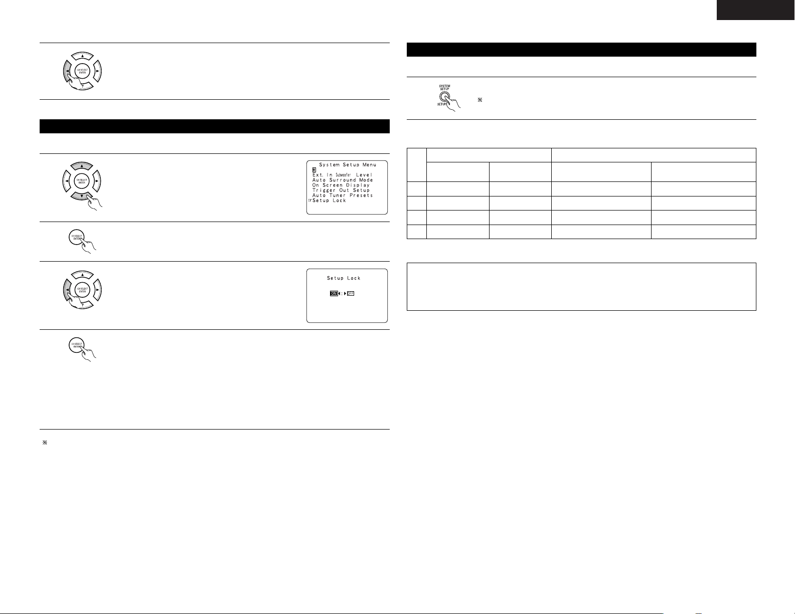
• The system setup settings can be locked so that they cannot be changed easily.
Protecting the setting
1
At the System Setup Menu select “Setup Lock”.
2
Switch to the Setup Lock screen.
3
Select “ON”, to lock the system setup settings.
4
Press the ENTER button to finalize the setting and exit the system setup mode.
When the setup lock function is activated, the settings listed below cannot be changed,
and “Setup Locked” is displayed when related buttons are operated.
• System setup settings
• Surround parameter settings
•Tone control settings
• Channel level settings (including test tones)
To unlock, press the System Setup button again and display the Setup Lock screen, then
select “OFF” and press “ENTER”.
System setup is complete. Once these settings are made, there is no need to change them unless
different AV components are connected or the speakers are repositioned.
This button can be pressed at any time during the system setup process to complete the process.
After completing system setup
1
At the System Setup Menu, press the SYSTEM SETUP button.
The changed settings are entered and the on-screen display turns off.
• On-screen display signals
1
2
3
4
Signals input to the AVR-2803 On-screen display signal output
VIDEO signal input
jack (yellow)
S-video signal
input jack
VIDEO MONITOR OUT video
signal output jack (yellow)
S-video MONITOR OUT video
signal output jack
E
C
C
E
E
E
C
C
C
C
E
E
C
E
C
C
(C: Signal
E
:
No signal)(
C
: On-screen signals output
E
:
On-screen signals not output)
NOTES:
• The on-screen display signals are not output from the color difference (component) video signal
MONITOR OUT jacks.
• For 4 above, the on-screen display signals are output to the VIDEO MONITOR OUT video signal output
jack (yellow) if the monitor TV is not connected to the S-video MONITOR OUT video signal output jack.
Page 18
18
ENGLISH
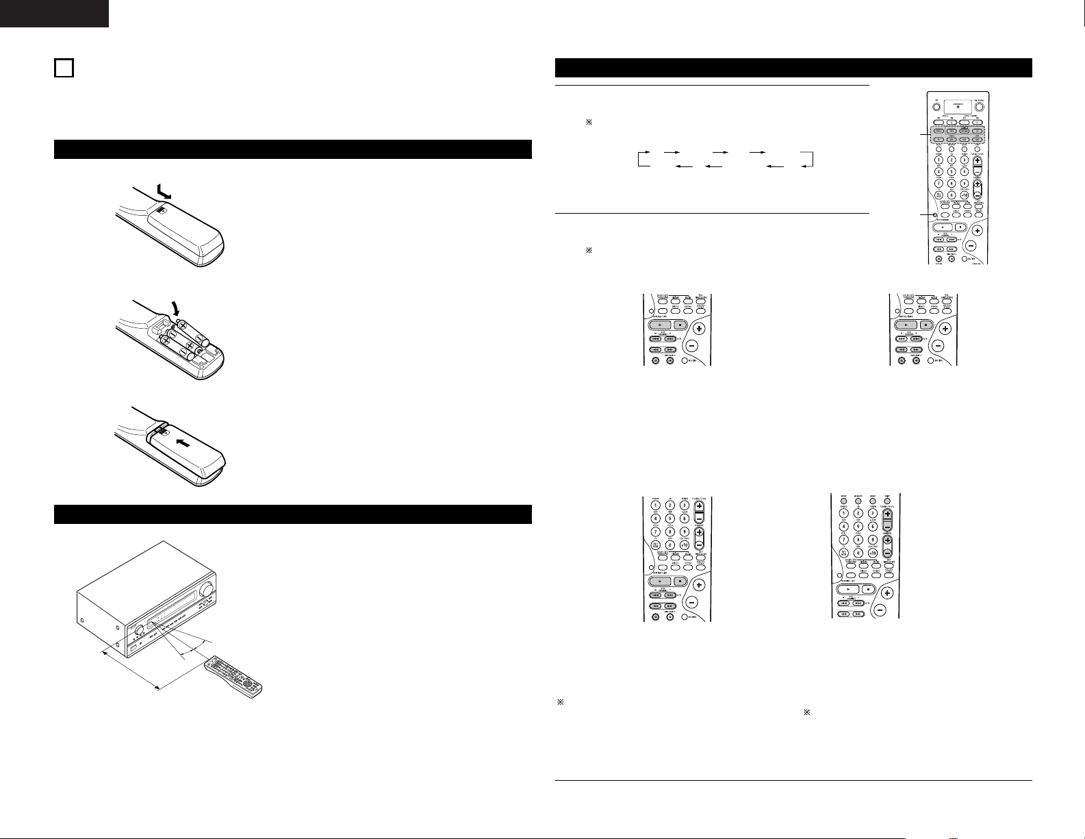
B
• Point the remote control unit at the remote sensor
on the main unit as shown on the diagram.
• The remote control unit can be used from a straight
distance of approximately 7 meters from the main
unit, but this distance will be shorter if there are
obstacles in the way or if the remote control unit is
not pointed directly at the remote sensor.
• The remote control unit can be operated at a
horizontal angle of up to 30 degrees with respect to
the remote sensor.
NOTES:
• It may be difficult to operate the remote control
unit if the remote sensor is exposed to direct
sunlight or strong artificial light.
• Do not press buttons on the main unit and remote
control unit simultaneously. Doing so may result in
malfunction.
• Neon signs or other devices emitting pulse-type
noise nearby may result in malfunction, so keep
the set as far away from such devices as possible.
Approx. 7 m
30°
30°
Using the remote control unit
8
REMOTE CONTROL UNIT
• The included remote control unit (RC-924) can be used to operate not only the AVR-2803 but other remote
control compatible DENON components as well. In addition, the memory contains the control signals for
other remote control units, so it can be used to operate non-Denon remote control compatible products.
Inserting the batteries
q Remove the remote control unit’s rear cover.
w Set three R6P/AA batteries in the battery
compartment in the indicated direction.
e Put the rear cover back on.
Notes on Batteries
• Use R6P/AA batteries in the remote control unit.
• The batteries should be replaced with new ones
approximately once a year, though this depends on
the frequency of usage.
• Even if less than a year has passed, replace the
batteries with new ones if the set does not operate
even when the remote control unit is operated
nearby the set. (The included battery is only for
verifying operation. Replace it with a new battery as
soon as possible.)
• When inserting the batteries, be sure to do so in the
proper direction, following the “≈” and “√” marks
in the battery compartment.
•To prevent damage or leakage of battery fluid:
• Do not use a new battery together with an old
one.
• Do not use two different types of batteries.
• Do not short-circuit, disassemble, heat or
dispose of batteries in flames.
• Remove the batteries from the remote control unit
when you do not plan to use it for an extended
period of time.
• If the battery fluid should leak, carefully wipe the
fluid off the inside of the battery compartment and
insert new batteries.
• When replacing the batteries, have the new
batteries ready and insert them as quickly as
possible.
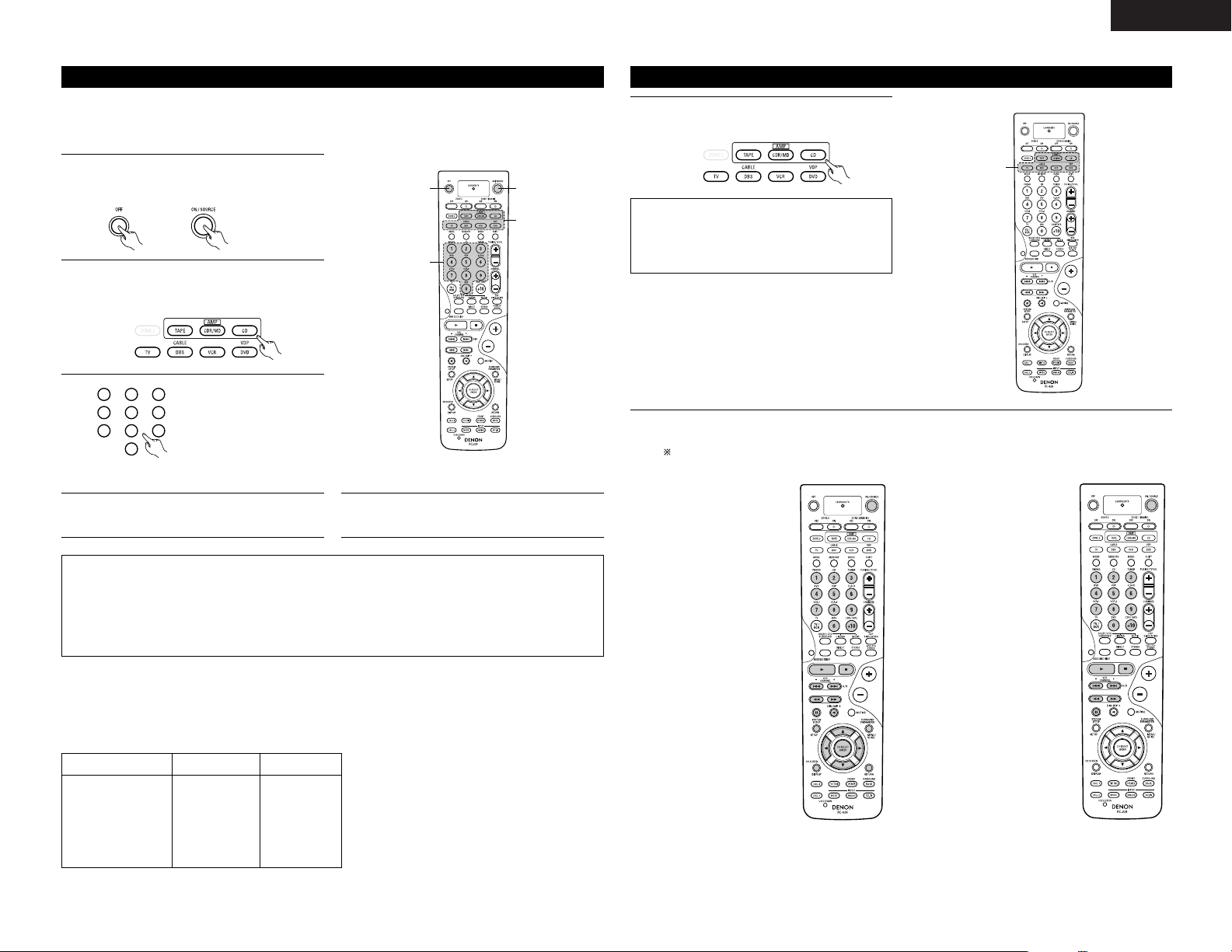
1
1
Operating DENON audio components
1
Use the mode selector buttons to select the component you want
to operate.
The function will change one step in the sequence described
below each time the MODE SELECT button is pressed.
2
Operate the audio component.
• For details, refer to the component’s operating instructions.
It may not be possible to operate some models.
1. CD player (CD) system buttons 2. Tape deck (TAPE) system buttons
6, 7 : Manual search (forward and reverse)
2 : Stop
1 : Play
8, 9 : Auto search (to beginning of track)
3 : Pause
DISC SKIP + : (for CD changers only)
6 : Rewind
7 :Fast forward
2 : Stop
1 : Forward play
3 : Pause
0 : Reverse play
A/B : Switch between sides A and B
3. MD recorder (MD), CD recorder (CDR) system
buttons
6, 7 : Manual search (forward and reverse)
2 : Stop
1 : Play
8, 9 : Auto search (to beginning of track)
3 : Pause
Default setting = CDR
4. Tuner system buttons
TUNING +, – : Tuning up/down
BAND : Switch between AM and FM bands
MODE : Switch between AUTO and MANUAL
MEMORY : Preset memory
SHIFT : Switch preset channel range
CHANNEL +, – : Preset channel up/down
The tuner can be operated in the amplifier (CD, CDR/MD, or
TAPE) mode.
CD CDR/MD TAPE
DVD/VDP
ZONE2 TV DBS/CABLE VCR
Page 19
19
ENGLISH
The included remote control unit can be used to operate devices of different brands by registering the preset
number corresponding to the brand of your device.
For some models the remote control unit or the device may not operate properly. In this case, use the learning
function (page 20) to store your device’s remote control signals in the included remote control unit.
Preset memory
1
Press the power ON/SOURCE button and the
OFF button at the same time.
• The LEARNED/TX indicator flashes.
2
3
Referring to the included List
of Preset Codes, use the
number buttons to input the
preset code (a 4-digit
number) for the manufacturer
of the component whose
signals you want to store in
the memory.
1
2
3
456
789
0
4
When stored correctly, the mode button and
the LEARNED/TX indicator will light.
5
To store the codes of another component in the
memory, repeat steps 1 to 4.
1
3
1
2
Press the mode button of the equipment that is
to be entered to a preset memory.
• The mode button flashes.
NOTES:
• Depending on the model and year of manufacture, this function cannot be used for some models, even if
they are of makes listed on the included list of preset codes.
• Some manufacturers use more than one type of remote control code. Refer to the included list of preset
codes to change the number and check it out.
• The preset memory can be set for one component only among the following: CDR/MD, DVD/VDP
and DBS/CABLE.
The preset codes are as follows upon shipment from the factory and after resetting:
TV, VCR......................................................................HITACHI
CD, TAPE...................................................................DENON
CDR/MD ....................................................................DENON (CDR)
DVD/VDP ...................................................................DENON (DVD)
DBS/CABLE ...............................................................ABC (CABLE)
DVD preset codes
B
Model No.
DVD-900
DVD-1000
DVD-1500
DVD-2800
DVD-3800
DVD-A1
DVD-800
DVD-1600
DVD-2000
DVD-2500
DVD-3000
DVD-3300
0000 0001
Operating a component stored in the preset memory
1
Press the mode selector button for the
component you want to operate.
1
NOTE:
• For the DVD player remote control buttons,
function names may differ according to
manufactuer. Compare with the remote control
operation of the various components.
2
Operate the component.
• For details, refer to the component’s operating instructions.
Some models cannot be operated with this remote control unit.
1. Digital video disc player
(DVD, DVD SETUP) system
buttons
POWER : Power on/standby
(ON/SOURCE)
6,7 : Manual search
(forward and reverse)
2 : Stop
1 : Play
8,9 : Auto search
(to beginning of track)
3 : Pause
0 ~ 9, +10 : 10 key
DISC SKIP + : Disc skip
(for DVD changer only)
DISPLAY : Display
MENU : Menu
RETURN : Return
SETUP : Setup
ENTER : Enter setting
•, ª,
0, 1
: Cursor up, down, left
and right
2. Video disc player (VDP)
system buttons
POWER : Power on/standby
(ON/SOURCE)
6,7 : Manual search
(forward and reverse)
2 : Stop
1 : Play
8,9 : Auto search (cue)
3 : Pause
0~9, +10 : 10 key
Page 20

20
ENGLISH
3. Video deck (VCR) system
buttons
POWER : Power on/standby
(ON/SOURCE)
6,7 : Manual search
(forward and reverse)
2 : Stop
1 : Play
3 : Pause
Channel +, – : Channels
4. Monitor TV (TV), digital
broadcast satellite (DBS)
tuner and cable (CABLE)
system buttons
POWER : Power on/standby
(ON/SOURCE)
MENU : Menu
•, ª,
0, 1
: Cursor up, down,
left and right
ENTER : Enter
CHANNEL : Switch channels
+, –
0~9, +10 : Channels
TV/VCR : Switch between TV
and video player
TV VOL +, – : Volume up/down
DISPLAY : Switch display
RETURN : Return
NOTES:
• For this CD, CDR, MD and TAPE components, buttons can be operated in the same way as for Denon audio
components.
• The television can be operated in the DVD/VDP, VCR and TV modes.
If your AV component is not a DENON product or if it cannot be operated using the preset memory, it can be
controlled with the included remote control unit by storing its remote control signals in the remote control unit.
For some remote control signals it is not possible to “learn” the signals or the device will not operate properly.
In such cases use the remote control unit included with the device to operate it.
Learning function
1
Press the USE/LEARN button with the tip of a
pen etc., to set the learn mode.
• Both the mode selector buttons and
LEARNED/TX indicator flash.
2
Press the mode button of the equipment for
which learning is desired.
• Mode button and LEARNED/TX indicator
flash.
2
1, 3, 7
3
Press the button that is to be learned.
The LEARNED/TX indicator stops flashing and
the mode button lights.
• Mode button and LEARNED/TX indicator
flashed if a button that cannot be “learned” is
pressed.
•To cancel, press the USE/LEARN button.
4
5
Point the remote control units directly at each
other and press and hold
in the button on the
other remote control
unit which you want
to “learn”.
Other remote
control unit
6
To “learn” other buttons, repeat steps 2 to 5.
7
Once the learning operation is completed, press
the USE/LEARN button again.
The mode button and the LEARNED/TX
indicator stop flashing and the learning mode is
cancelled.
Flashes
The mode button and the LEARNED/TX
indicator lights, release the button
on the other remote control unit.
• The mode button and the
LEARNED/TX indicator start
flashing again.
Check that the stored
codes work properly.
NOTES:
• If the codes could not be stored, the
LEARNED/TX indicator start flashing rapidly. For
limited number of models, codes cannot be
stored in RC-924.
• If the mode button and LEARNED/TX indicator
start flashing rapidly, this means that the
memory is already full, and the code you have
just attempted to store was not stored.
To “learn” that code, first perform the resetting
operation. (See page 22.)
Page 21
21
ENGLISH
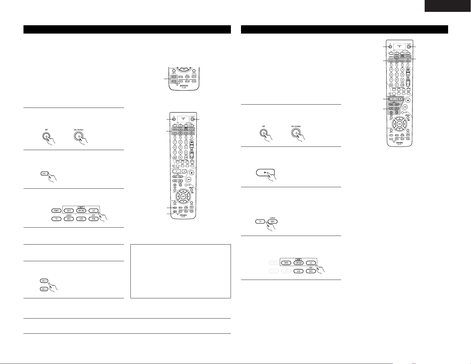
The accessorious remote control unit is equipped with “system call” function allowing a series of remote control
signals to be transmitted by pressing a single button.
This function can be used for example to turn on the amplifier’s power, select the input source, turn on the
monitor TV’s power, turn on the source component’s power and set the source to the play mode, all at the touch
of a button.
System call
1
Press the power ON/SOURCE button and the
OFF button at the same time.
• The LEARNED/TX indicator flashes.
2
Press the CALL 1 button.
• The mode selector buttons and LEARNED/TX
indicator flash.
3
2, 6
6
11
(1) System call buttons
Up to 10 signals each can be stored at the
“CALL1” and “CALL2” buttons.
(2) Storing system call signals
3
Press the mode buttons of the equipment that
is to be registered to System Call.
1
4
Press the buttons whose remote control signals
you want to store one by one.
5
Repeat steps 3 and 4 to register the desired
buttons.
6
Press the CALL1 or CALL2 button and register
System Call.
NOTES:
• The remote control signals for the buttons
pressed while storing the system call signals are
transmitted when the buttons are pressed, so
cover the remote sensor or take other measures
so that the components do not operate while
the signals are being stored.
• The mode button and LEARNED/TX indicator
flashing rapidly if you have already stored the
maximum number of signals.
1
Press the button at which the system call signals have been stored.
• The stored signals are transmitted successively.
(3) Using the system call function
Punch Through
(1) Punch through button
Buttons used in the CD, CDR/MD, TAPE,
DVD/VDP, and VCR modes can be assigned to the
buttons shown on the diagram at the right which
are not normally used in the TV and DBS/CABLE
modes.
For example, when the CD mode is set to the
punch through mode in the TV mode, the CD
mode’s PLAY, STOP, MANUAL SEARCH, AUTO
SEARCH, PAUSE and DISC SKIP buttons’ signals
are sent in the TV mode.
1
4
1
3
2
(1)
1
Press the power ON/SOURCE button and the
OFF button at the same time.
• The LEARNED/TX indicator flashes.
2
Press the 1 (play) button.
• TV and DBS/CABLE mode buttons and
LEARNED/TX indicator flash.
(2) Making the punch through setting
3
Press the mode button of the equipment for
which Punch Through is to be set.
• The CD, CDR/MD, TAPE, DVD/VDP, and VCR
mode buttons and LEARNED/TX indicator will
flash.
4
Press the mode button of the equipment that is
to be punched through.
• The mode button that was set will light.
Page 22
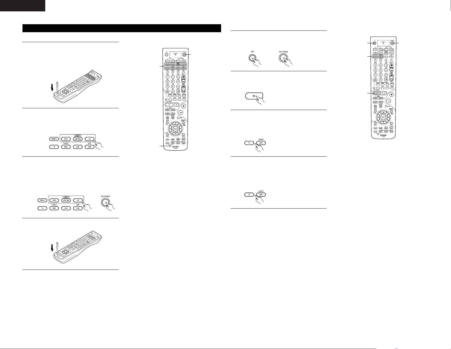
22
ENGLISH
Resetting
1
Press the USE/LEARN button with the tip of a
pen, etc., to set the learn mode.
• The mode selector buttons and LEARNED/TX
indicator flash.
2
Press the mode button of the equipment that is
to be reset.
• Mode button and LEARNED/TX indicator
flash.
(1) Resetting “learned” buttons
3
2, 3
1, 4
3
Hold for 4 seconds or longer the mode button of
the equipment that is to be reset and the
ON/SOURCE button.
• The mode button and the LEARNED/TX
indicator will again flash, and the learned
remote control signal of the selected
equipment will be deleted.
4
Press the USE/LEARN button.
Flashes
1
Press the power ON/SOURCE button and the
OFF button at the same time.
• The LEARNED/TX indicator flashes.
2
Press the 1 (play) button.
• TV and DBS/CABLE mode buttons and
LEARNED/TX indicator flash.
(2) Resetting the punch through setting
11
3, 4
2
3
Press the mode button of the equipment (TV or
DBS/CABLE) that is to be reset.
• The CD, CDR/MD, TAPE, DVD/VDP, and VCR
mode buttons and LEARNED/TX indicator will
flash.
4
Press the mode button of the equipment that is
to be reset again.
• During the resetting operation, the selected
mode button and the LEARNED/TX indicator
will light; they will return to steady state upon
completion.
Page 23
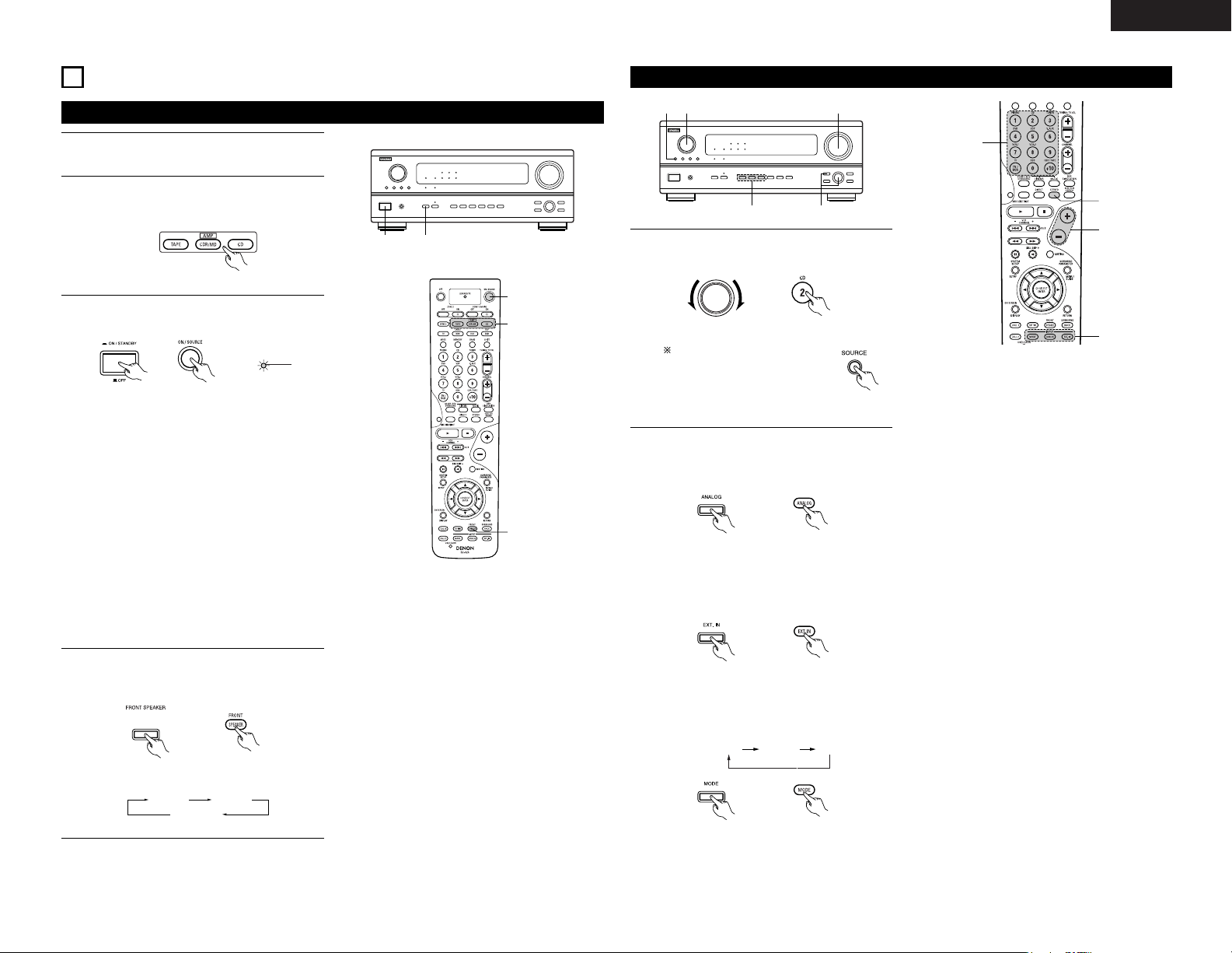
23
ENGLISH
9
OPERATION
3 4
3
4
2
Before operating
1
Refer to “CONNECTIONS” (pages 4 to 8) and
check that all connections are correct.
2
Select “AMP mode” using the TAPE,
CDR/MD or CD button. (only when operating
with the remote control unit)
ON/STANDBY
Lights
(Main unit) (Remote control unit)
• ¢ ON/STANDBY
The power turns on and “ON/STANDBY”
indicator is light.
Several seconds are required from the time
the power operation switch is set to the “¢
ON/STANDBY” position until sound is output.
This is due to the built-in muting circuit that
prevents noise when the power switch is
turned on and off.
Set the power operation switch to this
position to turn the power on and off from the
included remote control unit (RC-924).
• £ OFF
The power turns off and “ON/STANDBY”
indicator is off.
In this position, the power cannot be turned
on and off from the remote control unit (RC-
924).
3
Turn on the power.
Press the POWER operation switch (button).
(Remote control unit)
4
The front speakers switch as shown below
each time the FRONT SPEAKER button is
pressed.
(Main unit) (Remote control unit)
FRONT A FRONT B
FRONT A+B
115
2 3
Playing the input source
1
5
3
2
1
Select the input source to be played.
Example: CD
To select the input source
when ZONE2/REC OUT or
TUNING PRESET is selected,
press the SOURCE button
then operate the input function
selector.
FUNCTION
(Main unit) (Remote control unit)
AUTO PCM DTS
• Selecting the external input (EXT. IN) mode
Press the EXT. IN (on the EXT. IN button on
the remote control unit) to switch the external
input.
(Main unit) (Remote control unit)
• Selecting the AUTO, PCM and DTS modes
The mode switches as shown below each
time the INPUT MODE button is pressed.
Input mode selection function
Different input modes can be selected for the different
input sources. The selected input modes for the separate
input sources are stored in the memory.
q AUTO (auto mode)
In this mode, the types of signals being input to the
digital and analog input jacks for the selected input
source are detected and the program in the AVR2803’s surround decoder is selected automatically
upon playback. This mode can be selected for all input
sources other than PHONO and TUNER.
The presence or absence of digital signals is detected,
the signals input to the digital input jacks are identified
and decoding and playback are performed
automatically in DTS, Dolby Digital or PCM (2 channel
stereo) format. If no digital signal is being input, the
analog input jacks are selected.
Use this mode to play Dolby Digital signals.
w PCM (exclusive PCM signal playback mode)
Decoding and playback are only performed when PCM
signals are being input.
Note that noise may be generated when using this
mode to play signals other than PCM signals.
e DTS (exclusive DTS signal playback mode)
Decoding and playback are only performed when DTS
signals are being input.
r ANALOG (exclusive analog audio signal playback
mode)
The signals input to the analog input jacks are decoded
and played.
t EXT. IN (external decoder input jack selection mode)
The signals being input to the external decoder input
jacks are played without passing through the surround
circuitry.
NOTE:
• Note that noise will be output when CDs or LDs
recorded in DTS format are played in the “PCM”
(exclusive PCM signal playback) or “ANALOG”
(exclusive PCM signal playback) mode. Select the
AUTO or DTS mode when playing signals recorded in
DTS from a laser disc player or CD player.
(Main unit)
2
Select the input mode.
• Selecting the analog mode
Press the ANALOG button to switch to the
analog input.
(Main unit) (Remote control unit)
(Main unit) (Remote control unit)
Page 24
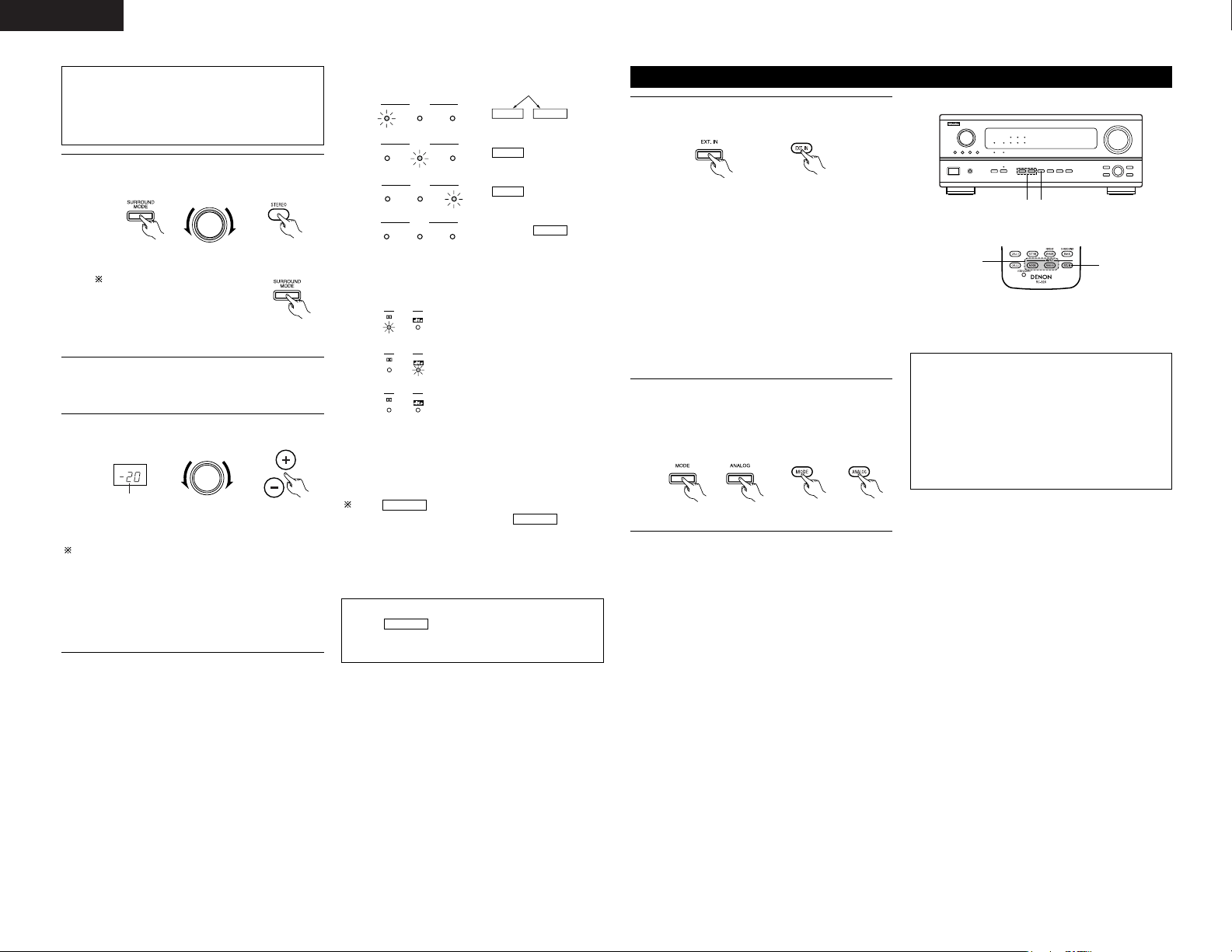
24
ENGLISH
Note on playing a source encorded with DTS
• Noise may be generated at the beginning of
playback and while searching during DTS
playback in the AUTO mode. If so, play in the
DTS mode.
3
Select the play mode.
Example: Stereo
(Main unit) (Remote control unit)
The volume can be adjusted within the range of
–80 to 0 to 18 dB, in steps of 0.5 dB. However,
when the channel level is set as described on page
13 or page 28, if the volume for any channel is set
at +1 dB or greater, the volume cannot be adjusted
up to 18 dB. (In this case the maximum volume
adjustment range is “18 dB — (Maximum value of
channel level)”.)
Input mode when playing DTS sources
• Noise will be output if DTS-compatible CDs or LDs
are played in the “ANALOG” or “PCM” mode.
When playing DTS-compatible sources, be sure to
connect the source component to the digital input
jacks (OPTICAL/COAXIAL) and set the input mode to
“DTS”.
4
Start playback on the selected component.
• For operating instructions, refer to the
component’s manual.
5
Adjust the volume.
MASTER VOLUME
(Main unit) (Remote control unit)
The volume level is
displayed on the
master volume level
display.
SELECT
To select the surround mode
while adjusting the surround
parameters, channel volume or
tone control, press the
surround mode button then
operate the selector.
(Main unit)
Input mode display
ANALOGDIGITAL
DIGITAL
DIGITAL
ANALOG
AUTO
INPUT
PCM DTS
AUTO
INPUT
PCM DTS
AUTO
INPUT
PCM DTS
AUTO
INPUT
PCM DTS
• In the AUTO mode
• In the DIGITAL PCM mode
• In the DIGITAL DTS mode
• In the ANALOG mode
One of these lights, depending on
the input signal.
Input signal display
SIGNAL
DIGITAL
DIGITAL
DIGITAL
SIGNAL
SIGNAL
• DOLBY DIGITAL
• DTS
• PCM
The indicator lights when digital signals
are being input properly. If the indicator
does not light, check whether the digital input
component setup (page 14) and connections are
correct and whether the component’s power is
turned on.
DIGITAL
DIGITAL
NOTE:
•The indicator will light when playing
CD-ROMs containing data other than audio
signals, but no sound will be heard.
DIGITAL
Playback using the external input (EXT. IN) jacks
• When the input mode is set to the external input
(EXT. IN), the surround mode (DIRECT, STEREO,
DOLBY/DTS SURROUND, 5/7CH STEREO or DSP
SIMULATION) cannot be set.
NOTES:
• In play modes other than the external input
mode, the signals connected to these jacks
cannot be played. In addition, signals cannot be
output from channels not connected to the input
jacks.
• The external input mode can be set for any input
source. To watch video while listening to sound,
select the input source to which the video signal
is connected, then set this mode.
1
Set the external input (EXT. IN) mode.
Press the EXT. IN to switch the external input.
Once this is selected, the input signals
connected to the FL (front left), FR (front right),
C (center), SL (surround left), SR (surround
right), SBL (surround back left) and SBR
(surround back right) channels of the EXT. IN
jacks are output directly to the front (left and
right), center, surround (left and right) and
surround back (left and right) speaker systems
as well as the pre-out jacks without passing
through the surround circuitry.
In addition, the signal input to the SW
(subwoofer) jack is output to the PRE OUT
SUBWOOFER jack.
(Main unit) (Remote control unit)
2
Cancelling the external input mode
To cancel the external input (EXT. IN) setting,
press the input mode (AUTO, PCM, DTS) or
ANALOG button to switch to the desired input
mode. (See page 23.)
(Main unit) (Remote control unit)
2
1
21
Page 25
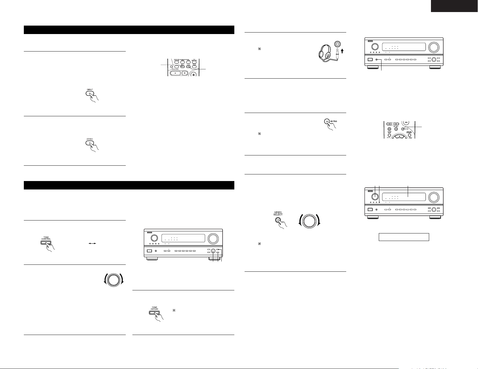
25
ENGLISH
Playing audio sources (CDs and DVDs)
1
2
The AVR-2803 is equipped with two 2-channel playback modes exclusively for music.
Select the mode to suit your tastes.
1
DIRECT mode
Use this mode to achieve good quality 2channel sound while watching images. In this
mode, the audio signals bypass such circuits as
the tone circuit and are transmitted directly,
resulting in good quality sound.
(Remote control unit)
2
STEREO mode
Use this mode to adjust the tone and achieve
the desired sound while watching images.
(Remote control unit)
2 13
BASS TREBLE
[1] Adjusting the sound quality (TONE)
• The tone control function will not work in the Direct mode.
• The tone control setting only affects the front speakers.
• If the tone control function is used, the main volume cannot be adjusted up to 18 dB. (The maximum main
volume level differs in the different surround modes.)
After starting playback
1
The tone switches as follows each time the
TONE CONTROL button is pressed.
(Main unit)
2
With the name of the volume to
be adjusted selected, turn the
SELECT knob to adjust the level.
SELECT
(Main unit)
•To increase the bass or treble: Turn the control
clockwise. (The bass or treble sound can be
increased to up to +10 dB in steps of 2 dB.)
•To decrease the bass or treble: Turn the
control counterclockwise. (The bass or treble
sound can be decreased to up to –10 dB in
steps of 2 dB.)
3
If you do not want the bass and treble to be
adjusted, turn on the tone defeat mode.
(Main unit)
The signals do not pass
through the bass and treble
adjustment circuits, providing
higher quality sound.
1
[2] Listening over headphones
1
Use this to turn off the audio
output temporarily.
Press the MUTING button.
Cancelling MUTING
mode.
Press the MUTING button again or adjust
the main volume level.
(Remote control unit)
1
Plug the headphones’ plug into
the jack.
Connect the headphones to
the PHONES jack.
The pre-out output
(including the speaker
output) is automatically turned off when
headphones are connected.
NOTE:
To prevent hearing loss, do not raise the volume level
excessively when using headphones.
[3] Turning the sound off temporarily (MUTING)
1
1
Simulcast playback
Use this switch to monitor a video source other
than the audio source.
Press the VIDEO SELECT button, turn the
FUNCTION knob until the desired source
appears on the display.
111
[4]
Combining the currently playing sound with the desired image
Cancelling simulcast playback.
• Select “SOURCE” using the VIDEO
SELECT button and the FUNCTION knob.
• Switch the program source to the
component connected to the video input.
(Main unit)
FUNCTION
IN=V SOURCE
Display
PHONES
1
Page 26
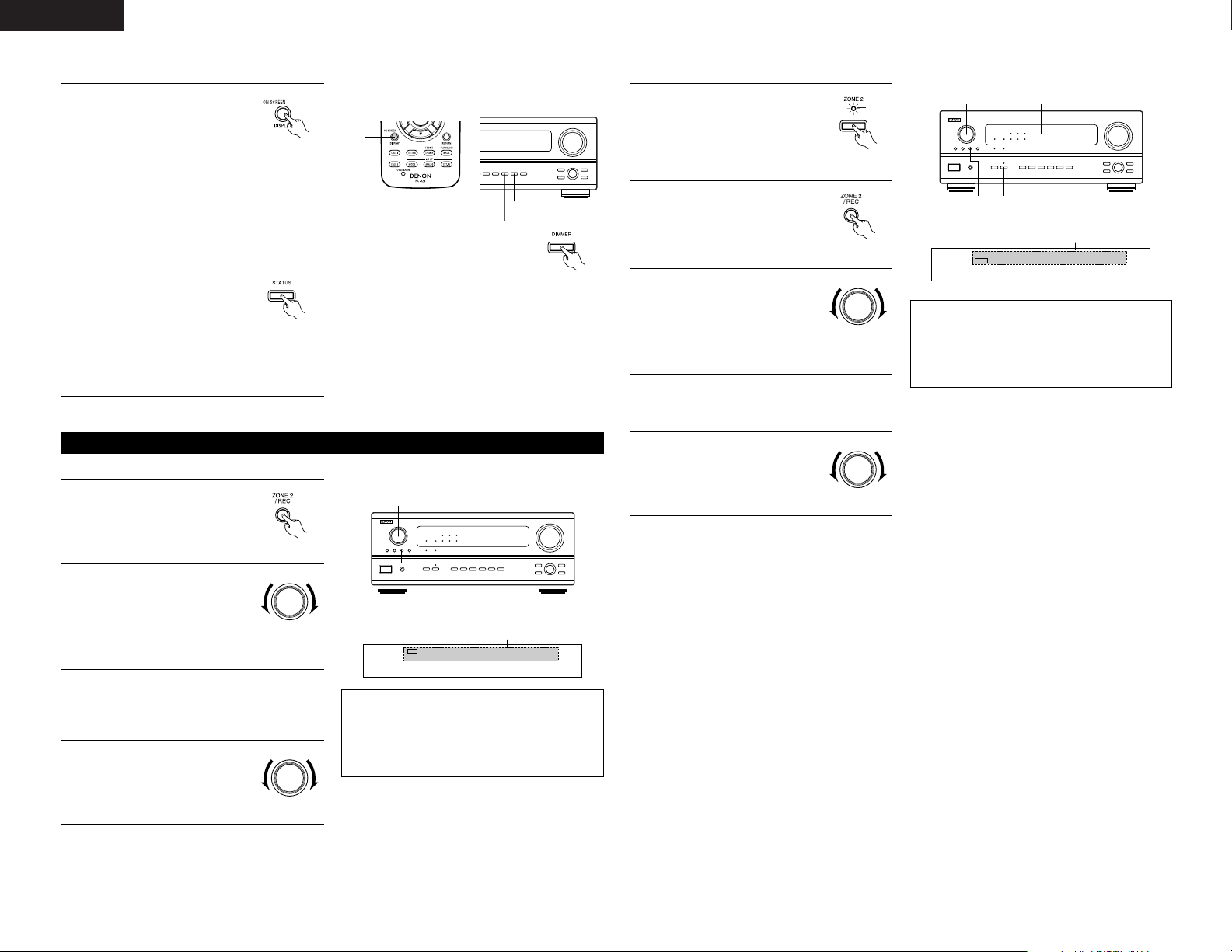
26
ENGLISH
[5]
Checking the currently playing program source, etc.
1
1
Using the dimmer function
• Use this to change the brightness of
the display.
The display brightness changes in
four steps (bright, medium, dim and
off) by pressing the main unit’s
DIMMER button repeatedly.
1
On screen display
• Each time an operation is
performed, a description of
that operation appears on
the display connected to the
unit’s VIDEO MONITOR OUT
jack.
Also, the unit’s operating status can be
checked during playback by pressing the
remote control unit’s ON SCREEN/DISPLAY
button.
Such information as the position of the input
selector and the surround parameter settings
is output in sequence.
Front panel display
• Descriptions of the unit’s
operations are also displayed
on the front panel display.
In addition, the display can
be switched to check the
unit’s operating status while
playing a source by pressing
the STATUS button.
(Remote control unit)
(Main unit)
(Main unit)
22,4
1
[1] Playing one source while recording another (REC OUT mode)
Multi-source recording/playback
1
Press the ZONE2/REC button.
(Main unit)
Display
NOTES:
• Recording sources other than digital inputs
selected in the REC OUT mode are also output to
the Zone 2 preout jacks.
• Digital signals are not output from the REC
SOURCE or audio output jacks.
2
With “RECOUT SOURCE”
displayed, turn the FUNCTION
knob to select the source you
wish to record.
• The “REC” indicator and the
indicator of the selected
source light.
FUNCTION
(Main unit)
3
Set the recording mode.
• For operating instructions, refer to the manual
of the component on which you want to
record.
4
To cancel, turn the function
knob and select “SOURCE”.
• When “SOURCE” is selected,
the “REC” indicator turns off.
FUNCTION
(Main unit)
VCR -1 -2 V.AUX / TAPE
PHONO CD TUNER DVD / VDP TV / DBS
2
REC
RECOUT SOURCE
[2] Outputting a program source to an amplifier, etc., in a different room (ZONE2 mode)
2
Press the ZONE2/REC button.
(Main unit)
Display
NOTES:
• The signals of the source selected in the ZONE2
mode are also output from the VCR-1, VCR-2 and
CDR/TAPE recording output jacks.
• Digital signals are not output from the ZONE2
audio output jacks.
3
With “ZONE2 SOURCE”
displayed, turn the FUNCTION
knob and select the source you
wish to output.
• The “MULTI” indicator and
the indicator of the selected
source light.
FUNCTION
(Main unit)
4
Start playing the source to be output.
• For operating instructions, refer to the
manuals of the respective components.
VCR -1 -2 V.AUX / TAPE
PHONO CD TUNER DVD / VDP TV / DBS
2
MULTI
ZONE2 SOURCE
33,5
2
1
5
To cancel, turn the function
knob and select “SOURCE”.
• When “SOURCE” is selected,
the “MULTI” indicator turns
off.
FUNCTION
(Main unit)
1
Press the ZONE2 button.
(Main unit)
Light
Page 27
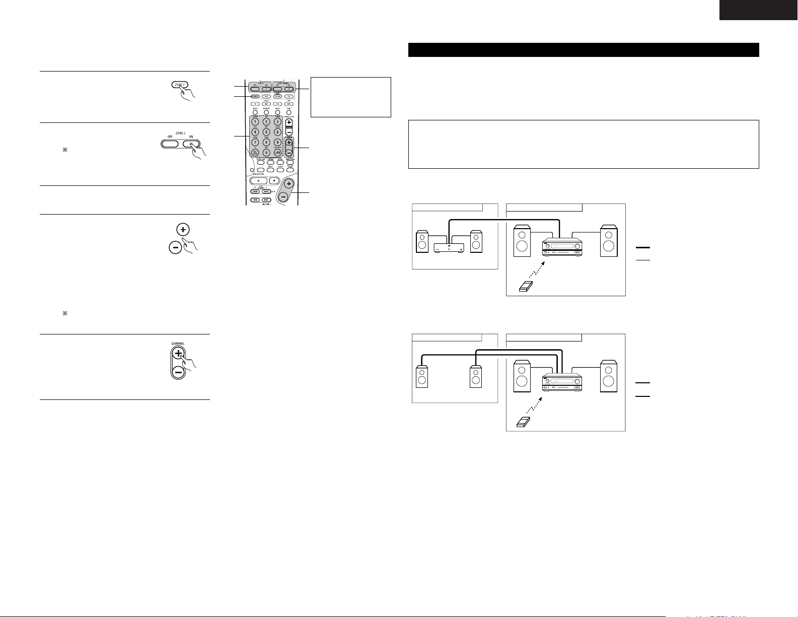
27
ENGLISH
4
The output level of the ZONE
2 OUT terminals can be
controlled using the
VOLUME + and - buttons on
the remote control unit.
The output level of ZONE 2 OUT can be
controlled only if ZONE2 vol. level is set
“Variable” at Zone2 Control in System Setup
Menu. (See page 16)
(Remote Control unit)
3
Press the input source button.
• The ZONE2 source switches directly.
[3] Remote control unit operations during multi-source playback (selecting the input source)
This operation is possible when ZONE2 mode is selected.
This operation is not possible in the REC OUT mode.
1
Select “ZONE2” using the
ZONE 2 button.
(Remote Control unit)
2
Press the ZONE2 “ON”
button.
To cancel the ZONE2
mode.
Press the ZONE2
“OFF” button.
3
2
1
4
5
(Remote Control unit)
DEFAULT SETTING (ZONE2 VOLUME
LEVEL) : - - - dB (MINIMUM)
5
When the ZONE2 SOURCE
function is set to TUNER,
the preset channel can be
selected using the
CHANNEL + and - buttons
on the remote control unit.
(Remote Control unit)
The main zone output
can be turned on and
off with the “MAIN
ON/OFF” button.
MULTI ZONE MUSIC ENTERTAINMENT SYSTEM
• When the outputs of the “ZONE 2” OUT terminals are wired and connected to integrated amplifiers installed
in other rooms, different sources can be played in rooms other than the main zone in which this unit and the
playback devices are installed. (Refer to ZONE 2 on the diagram below.)
• ZONE 2 SPEAKER OUT can be used when “ZONE2” is selected at System Setup Menu “Power Amp
Assignment”. In this case, Surround Back Speaker OUT cannot be used for MAIN ZONE. (See page 15.)
Multi-zone playback with multi-source
NOTES:
• For the AUDIO output, use high quality pin-plug cords and wire in such a way that there is no humming
or noise.
• For instructions on installation and operation of separately sold devices, refer to the devices’ operating
instructions.
2 MULTI ZONE MUSIC ENTERTAINMENT SYSTEM (When using PREOUT)
AVR-2803
B
B
ZONE 2 MAIN ZONE
INTEGRATED AMPLIFIER
ZONE 2 AUDIO signal cable
SPEAKER cable
*
Refer to CONNECTIONS on pages 4 to 8.
2 MULTI ZONE MUSIC ENTERTAINMENT SYSTEM (When using SPEAKER OUT)
AVR-2803
B
SYSTEM REMOTE
CONTROL UNIT RC-924
ZONE 2 MAIN ZONE
SYSTEM REMOTE
CONTROL UNIT RC-924
ZONE 2 SPEAKER cable
SPEAKER cable
*
Refer to CONNECTIONS on pages 4 to 8.
Page 28
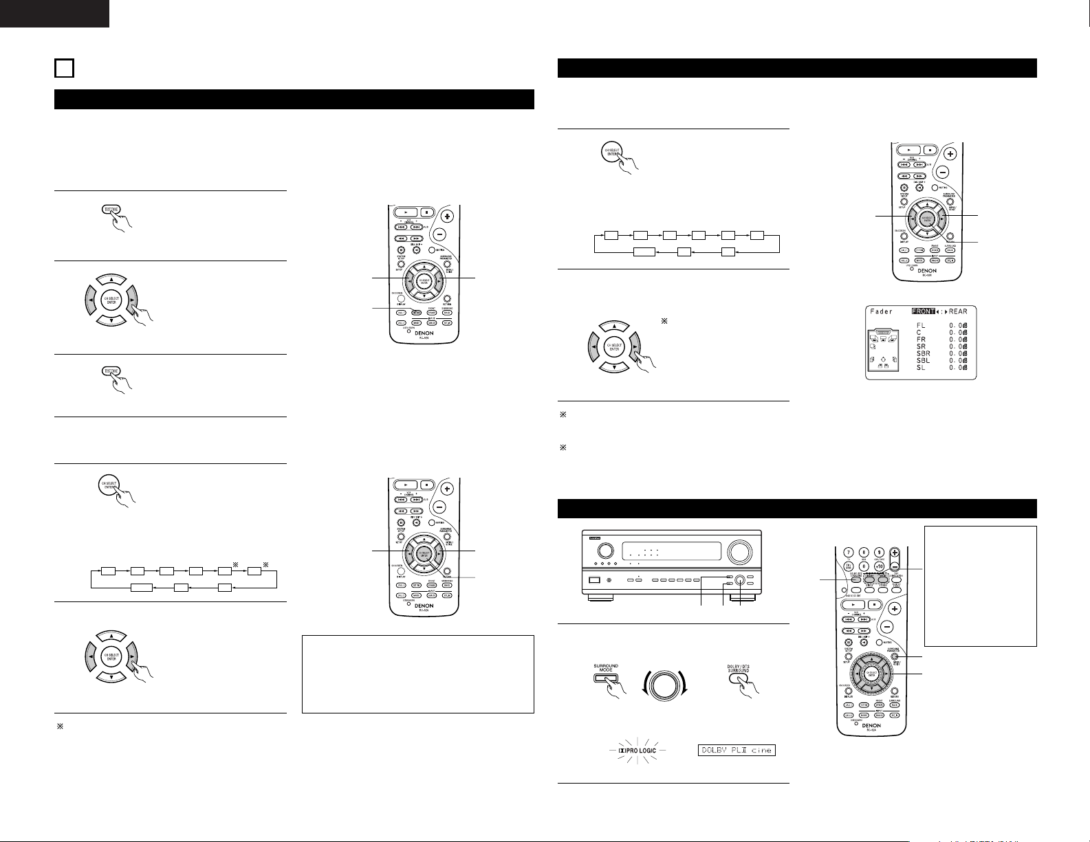
28
ENGLISH
10
SURROUND
Before playing with the surround function
• Before playing with the surround function, be sure to use the test tones to adjust the playback level from the
different speakers. This adjustment can be performed with the system setup (see page 13) or from the remote
control unit, as described below.
• Adjusting with the remote control unit using the test tones is only possible in the “Auto” mode and only
effective in the DOLBY/DTS SURROUND modes. The adjusted levels for the different modes are automatically
stored in the memory.
2
1, 3
2
1
Press the TEST TONE button.
• After adjusting using the test tones, adjust the channel levels either according to the playback sources or to
suit your tastes, as described below.
FL C FR SR SBR SBL
SLSW
FADER
1
Select the speaker whose
level you want to adjust.
2
2
2
1
(Remote control unit)
2
Test tones are output from
the different speakers. Use
the channel volume adjust
buttons to adjust so that the
volume of the test tones is
the same for all the
speakers.
(Remote control unit)
3
After completing the
adjustment, press the TEST
TONE button again.
(Remote control unit)
(Remote control unit)
The channel switches as shown below each
time the button is pressed.
Adjust the level of the selected speaker.
(Remote control unit)
When the surround back speaker setting is set
to “1spkr” for “Speaker Configuration”, this is
set to “SB”.
NOTES:
• The adjustment range for the different channels
is +12 dB to –12 dB.
• The sound from the subwoofer can be cut by
lowering the SW (subwoofer) setting one step
from –12 dB (setting it to “OFF”).
The channel whose channel level is adjusted
lowest can be faded to –12 dB using the fader
function.
If the channel levels are adjusted separately after
adjusting the fader, the fader adjustment values
are cleared, so adjust the fader again.
Fader function
• This function makes it possible to lower the volume of the front channels (FL, C and FR) or the rear channels
(SL, SR, SBL and SBR) together. Use it for example to adjust the balance of the sound from the different
positions when playing multi-channel music sources.
1
Select “FADER”.
This is only displayed when setting the fader control.
2
2
1
FL C FR SR SBR SBL
SLSW
FADER
(Remote control unit)
The channel switches in the order shown
below each time this button is pressed.
2
Press the 0 button to reduce the volume of
the front channels, the 1 button to reduce the
volume of the rear channels.
(Remote control unit)
The fader function does
not affect the SW channel.
Dolby Surround Pro Logic IImode
1
Select the Dolby Surround Pro Logic II mode.
• The Dolby Pro Logic indicator lights.
Light
(Main unit) (Remote control unit)
1 3, 5 1, 4, 6
SELECT
1
3
4, 5, 6
Display
The Dolby Surround
Pro Logic II Cinema or
Music mode can be
chosen directly by
pressing the CINEMA
or MUSIC button on
the remote control
unit during playback in
the Dolby Surround
Pro Logic II mode.
Page 29
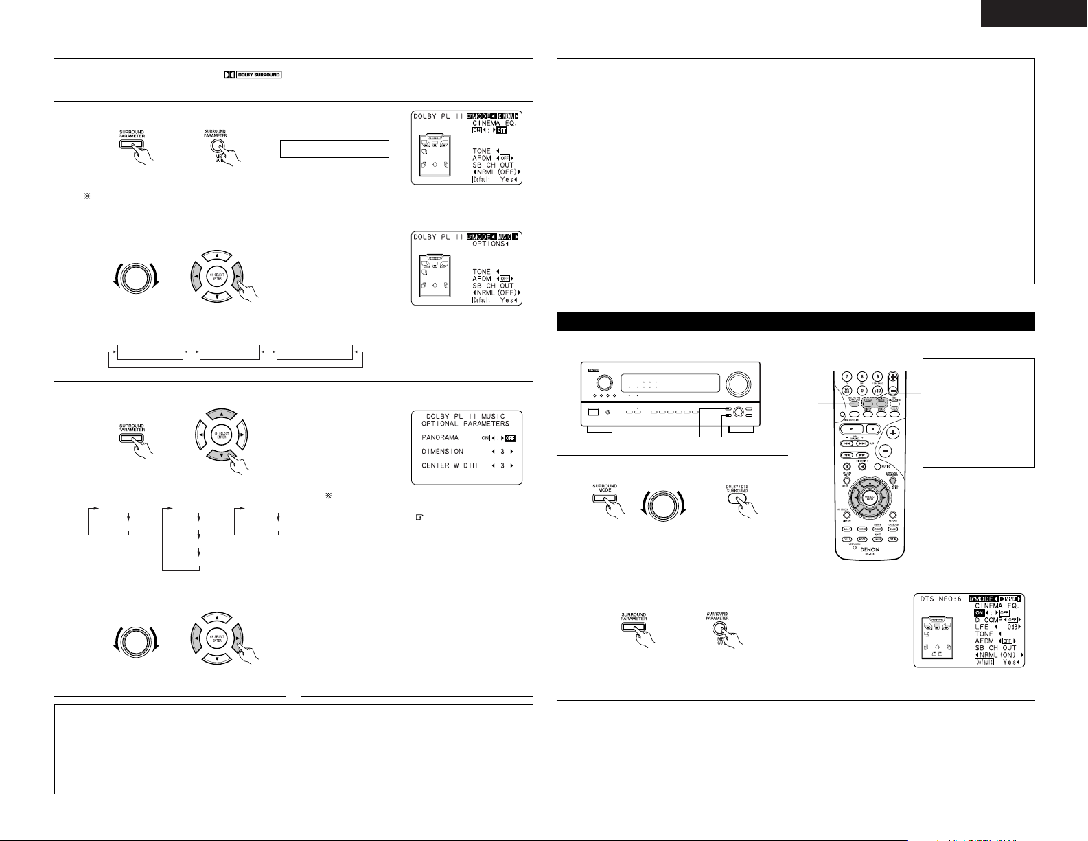
29
ENGLISH
2
Play a program source with the mark.
• For operating instructions, refer to the manuals of the respective components.
NOTES:
• There are four Dolby Surround Pro Logic modes (NORMAL, PHANTOM, WIDE and 3 STEREO). The AVR2803 sets the mode automatically according to the types of speakers set during the system setup process
(page 11).
• Dolby Surround Pro Logic II is a mode in which 2-channel sources are expanded into 5.1 channels.
To output a surround back channel in this mode, set the “SB CH OUT” surround parameter to “NON
MTRX”.
3
Set the surround parameter mode.
(Main unit) (Remote control unit)
MODE cinema
Display
The on-screen display differs according to whether the operation is
performed from the main unit or the remote control unit.
4
Select the play mode.
SELECT
(Main unit) (Remote control unit)
Display
MODE cinema MODE music MODE DOLBY PL
5
Select the various parameters. (See “Surround parameters q” for a description of the various parameters.)
(Main unit) (Remote control unit)
MODE DOLBY PL
CINEMA EQ
MODE CINEMA
CINEMA EQ
MODE MUSIC
PANORAMA
DIMENSION
CENTER WIDTH
When set with the on-screen display using
the remote control unit while in the MUSIC
mode, set the “ ” mark to “OPTION
0
”
using the • and ª cursor buttons, then press
the
0
cursor button.
Press the ENTER button to return to the
previous screen.
6
Set the various surround parameters.
SELECT
(Main unit) (Remote control unit)
7
When the surround parameters are set using
the buttons on the main unit, stop operating
buttons after completing the settings. The
settings are automatically finalized and the
normal display reappears after several seconds.
When the settings are made using the buttons
on the remote control unit, press the
SURROUND PARAMETER button to finish.
This is the screen when operated with
the remote control unit.
This is the screen when operated with
the remote control unit.
Surround parameters q
Pro Logic II Mode:
The Cinema mode is for use with stereo television shows and all programs encoded in Dolby Surround.
The Music mode is recommended as the standard mode for autosound music systems (no video), and is
optional for A/V systems.
The Dolby PL mode offers the same robust surround processing as original Pro Logic in case the source
contents is not of optimum quality.
Select one of the modes (“Cinema”, “Music” or “Dolby PL”).
Panorama Control:
This mode extends the front stereo image to include the surround speakers for an exciting “wraparound”
effect with side wall imaging.
Select “OFF” or “ON”.
Dimension Control:
This control gradually adjust the soundfield either towards the front or towards the rear.
The control can be set in 7 steps from 0 to 6.
Center Width Control:
This control adjust the center image so it may be heard only from the center speaker; only from the left/right
speakers as a phantom image; or from all three front speakers to varying degrees.
The control can be set in 8 steps from 0 to 7.
DTS NEO:6 mode
1
Select the DTS NEO:6 mode.
(Main unit) (Remote control unit)
1 3, 5 1, 4, 6
SELECT
1
3
4, 5, 6
The DTS NEO:6
Cinema or Music
mode can be chosen
directly by pressing
the CINEMA or
MUSIC button on the
remote control unit
during playback in the
DTS NEO:6 mode.
• Surround playback can be performed for the analog input and PCM digital input 2-channel signals.
2
Play a program source.
3
Set the surround parameter mode.
(Main unit) (Remote control unit)
This is the screen when operated with
the remote control unit.
Page 30
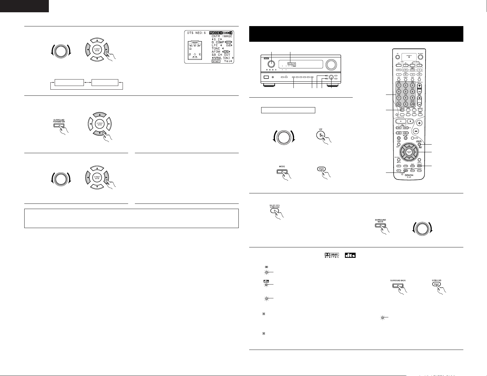
30
ENGLISH
4
Select the play mode.
SELECT
(Main unit) (Remote control unit)
Display
MODE cinema MODE music
This is the screen when operated with
the remote control unit.
13
2 4,5 2,631
1
2
1
4
3
5, 6
Dolby Digital mode (only with digital input) and DTS Surround mode
(only with digital input)
Playback with digital input
1
Select the input source.
q Select an input source set to digital
(COAXIAL/OPTICAL) (see page 14).
FUNCTION
(Main unit) (Remote control unit)
w Set the input mode to “AUTO” or “DTS”.
(Main unit) (Remote control unit)
5
Select the various parameters. (See “Surround parameters e” on page 34 for a description of the various
parameters.)
(Main unit) (Remote control unit)
NOTE:
• When “Default” is selected and the
0
cursor button is pressed, “MODE” and “TONE” are automatically
reset to the default values and “CINEMA EQ” is set to “OFF”.
6
Set the various surround parameters.
SELECT
(Main unit) (Remote control unit)
7
When the surround parameters are set using
the buttons on the main unit, stop operating
buttons after completing the settings. The
settings are automatically finalized and the
normal display reappears after several seconds.
When the settings are made using the buttons
on the remote control unit, press the
SURROUND PARAMETER button to finish.
2
Select the Dolby/DTS Surround mode.
(Remote control unit)
When performing this operation from the main unit’s
panel, press the SURROUND MODE button, then turn
the SELECT knob and select Dolby Pro logic II or DTS
NEO:6.
SELECT
(Main unit)
3
Play a program source with the , mark.
DIGITAL
• The DTS indicator lights when playing
DTS sources.
Light
SIGNAL
DETECT
• The SIGNAL DETECT indicator lights
when playing 6.1-channel surround
sources containing the identification
signal.
• The Dolby Digital indicator lights when
playing Dolby Digital sources.
Light
Light
Operate the SURROUND BACK button to
switch Surround Back CH ON/OFF.
When the SIGNAL DETECT indicator is lit, we
recommend turning the surround back channel
using the SURROUND BACK button on the remote
control unit and main unit during playback.
To use DTS 96/24 sources with the optimum
system, we recommend turning the surround back
channel off.
SURROUND
BACK CH
OUTPUT
• Lights when the Surround
Back CH is on
.
(Main unit) (Remote control unit)
Light
Page 31

31
ENGLISH
NOTE: When “Default” is selected and the 0cursor button is pressed, “CINEMA EQ.” and “D.COMP.” are
automatically turned off, “LFE” is reset, and the tone is set to the default value.
Surround parameters w
CINEMA EQ. (Cinema Equalizer):
The Cinema EQ function gently decreases the level of the extreme high frequencies, compensating for
overly-bright sounding motion picture soundtracks. Select this function if the sound from the front speakers
is too bright.
This function only works in the Dolby Pro Logic, Dolby Digital, DTS Surround, DTS NEO:6 and WIDE SCREEN
modes. (The same contents are set for all operating modes.)
D.COMP. (Dynamic Range Compression):
Motion picture soundtracks have tremendous dynamic range (the contrast between very soft and very loud
sounds). For listening late at night, or whenever the maximum sound level is lower than usual, the Dynamic
Range Compression allows you to hear all of the sounds in the soundtrack (but with reduced dynamic range).
(This only works when playing program sources recorded in Dolby Digital or DTS.) Select one of the four
parameters (“OFF”, “LOW”, “MID” (middle) or “HI” (high)). Set to OFF for normal listening.
LFE (Low Frequency Effect):
This sets the level of the LFE (Low Frequency Effect) sounds included in the source when playing program
sources recorded in Dolby Digital or DTS.
If the sound produced from the subwoofer sounds distorted due to the LFE signals when playing Dolby Digital
or DTS sources when the peak limiter is turned off with the subwoofer peak limit level setting (system setup
menu), adjust the level as necessary.
Program source and adjustment range:
1. Dolby Digital: –10 dB to 0 dB
2. DTS Surround: –10 dB to 0 dB
When DTS encoded movie software is played, it is recommended that the LFE LEVEL be set to
0 dB for correct DTS playback.
When DTS encoded music software is played, it is recommended that the LFE LEVEL be set to
–10 dB for correct DTS playback.
TONE:
This adjusts the tone control. (See “Surround parameters e” on page 34.)
SB CH OUT:
(1) Dolby Digital/DTS source
“OFF” ......................Playback is conducted without using the surround back speaker.
“NON MTRX” ..........Playback is conducted using the surround back speaker.
The same signals those of the surround channels are output from the surround back
channels.
“MTRX ON”.............Playback is conducted using the surround back speaker.
Surround back channel is reproduced using digital matrix processing.
“NRML (OFF)”.........Playback is conducted without using the surround back speaker.
“NRML (ON)” ..........Playback is conducted using the surround back speaker.
Surround back channel is reproduced using digital matrix processing.
(2) Other source
“OFF” ......................Playback is conducted without using the surround back speaker.
“ON”........................Playback is conducted using the surround back speaker.
NOTE: This operation can be performed directly using the “SURROUND BACK” button on the main unit’s
panel.
4
Display the surround parameter menu.
(Main unit) (Remote control unit)
5
Select the various parameters.
(Main unit) (Remote control unit)
6
Adjust the parameter settings.
SELECT
(Main unit) (Remote control unit)
NOTE: The display on the screen differs depending on whether you are performing the operation from
the main unit or the remote control unit.
2 Dialogue Normalization
The dialogue normalization function is activated automatically when playing Dolby Digital program sources.
Dialogue normalization is a basic function of Dolby Digital which automatically normalizes the dialog level
(standard level) of the signals which are recorded at different levels for different program sources, such as DVD,
DTV and other future formats that will use Dolby Digital.
These contents can be verified with the STATUS button.
The number indicates the normalization level when the currently playing
program is normalized to the standard level.
OFFSET - 4dB
Page 32

32
ENGLISH
(Remote control unit)
The surround mode switches in the following order
each time the DSP SIMULATION button is pressed:
JAZZ CLUBMONO MOVIE ROCK ARENA
VIDEO GAME
VIRTUAL MATRIX
DSP surround simulation
1
Select the surround mode for the input channel.
3
1
2, 4
2
Display the surround parameter screen on the monitor.
The screen for the selected surround mode appears.
(Remote control unit)
3
Set the parameters.
(Remote control unit)
4
To end the setting mode, press the surround parameter button again.
NOTES:
• When “Default” is selected and the
0
courser button is pressed, “CINEMA EQ.” and “D.COMP.” are
automatically turned off, “ROOM SIZE” is set to “medium”, “EFFECT LEVEL” to “10”, “DELAY TIME” to
“30ms” and “LFE” to “0 dB”.
• The “ROOM SIZE” expresses the expansion effect for the different surround modes in terms of the size
of the sound field, not the actual size of the listening room.
•To operate the surround mode and surround parameters from the remote control unit.
(Remote control unit)
1
2
4
5
6
7
VIDEO GAME
ROCK ARENA
JAZZ CLUB
VIRTUAL
MATRIX
5CH/7CH STEREO
Use this to enjoy video game sources.
Use this mode to achieve the feeling of a live concert in an arena with reflected sounds coming
from all directions.
This mode creates the sound field of a live house with a low ceiling and hard walls. This mode
gives jazz a very vivid realism.
Select this mode to enjoy a virtual sound field, produced from the front 2-channel speakers.
Select this to emphasize the sense of expansion for music sources recorded in stereo. Signals
consisting of the difference component of the input signals (the component that provides the
sense of expansion) processed for delay are output from the surround channel.
In this mode, the signals of the front left channel are output from the left surround channel, the
signals of the front right channel are output from the right surround channel, and the same (inphase) component of the left and right channels is output from the center channel. This mode
provides all speaker surround sound, but without directional steering effects, and works with any
stereo program source.
11
DSP SURROUND SIMULATION
Surround modes and their features
• The AVR-2803 is equipped with a high performance DSP (Digital Signal Processor) which uses digital signal
processing to synthetically recreate the sound field. One of seven preset surround modes can be selected
according to the program source and the parameters can be adjusted according to the conditions in the
listening room to achieve a more realistic, powerful sound. These surround modes can also be used for
program sources not recorded in Dolby Surround Pro Logic or Dolby Digital.
3
MONO MOVIE
(NOTE 1)
Select this when watching monaural movies for a greater sense of expansion.
Depending on the program source being played, the effect may not be very noticeable.
In this case, try other surround modes, without worrying about their names, to create a sound field suited
to your tastes.
NOTE 1: When playing sources recorded in monaural, the sound will be one-sided if signals are only input to
one channel (left or right), so input signals to both channels. If you have a source component with only
one audio output (monophonic camcorder, etc.) obtain a “Y” adaptor cable to split the mono output
to two outputs, and connect to the L and R inputs.
Personal Memory Plus
This set is equipped with a personal memorize function that automatically memorizes the surround modes
and input modes selected for the input different sources. When the input source is switched, the modes set
for that source last time it was used are automatically recalled.
The surround parameters, tone control settings and playback level balance for the different output
channels are memorized for each surround mode.
Page 33

33
ENGLISH
SELECT
(Main unit)
1
Turn the SELECT knob to select the surround
mode.
1 2 1,3
2
Press the SURROUND PARAMETER button.
Press and hold in the surround parameter button to select the parameter you want to
set.
• The parameters which can be set differ for the different surround modes. (Refer to
“Surround Modes and Parameters” on pages 34, 35.)
(Main unit)
3
Display the parameter you want to adjust, then turn the SELECT knob to set it.
NOTE:
• When playing PCM digital signals or analog signals in the DOLBY PRO LOGIC II , DTS NEO:6 modes and
the input signal switches to a digital signal encoded in Dolby Digital, the Dolby surround mode switches
automatically. When the input signal switches to a DTS signal, the mode automatically switches to DTS
surround.
• Operating the surround mode and surround parameters from the main unit‘s panel.
• When turned clockwise
• When turned counterclockwise
DIRECT STEREO DOLBY PRO LOGIC II DTS NEO:6 5/7CH STEREO
DIRECT STEREO DOLBY PRO LOGIC
II DTS NEO:6 5/7CH STEREO
MONO MOVIE
MONO MOVIE
ROCK ARENAJAZZ CLUBVIDEO GAMEMATRIXVIRTUAL
ROCK ARENAJAZZ CLUBVIDEO GAMEMATRIXVIRTUAL
To select the surround mode while adjusting the surround parameters or tone control, press the
surround mode button then operate the selector.
(Main unit)
Tone control setting
• Use the tone control setting to adjust the bass and treble as desired.
•To operate the tone control from the remote control unit.
• The tone control setting only affects the front speakers.
• If the tone control function is used, the main volume cannot be adjusted up to 18 dB. (The maximum main
volume level differs in the different surround modes.)
1
Display the surround parameter
screen on the monitor.
The screen for the selected
surround mode appears.
“TONE” cannot be selected
in the Direct mode.
2, 3, 4
1, 6
5
(Remote control unit)
3
Switch to the Tone Control
screen.
Select Tone Defeat “OFF”.
(Remote control unit)
4
5
Enter the setting.
The surround menu screen reappears.
(Remote control unit)
6
To end the setting mode, press the surround parameter button again.
(Remote control unit)
(Remote control unit)
To select Bass or Treble.
(Remote control unit)
To set the level.
2
Select “TONE”.
(Remote control unit)
Page 34

34
ENGLISH
1
The tone switches as follows each time the
TONE CONTROL button is pressed.
•To operate the tone control from the main unit.
(Main unit)
1
TREBLE
0
BASS
2
With the name of the volume to be adjusted selected, turn the SELECT knob to adjust
the level.
•To increase the bass or treble:
Turn the control clockwise. (The bass or treble sound can be increased to up to +10 dB in
steps of 2 dB.)
•To decrease the bass or treble:
Turn the control clockwise. (The bass or treble sound can be decreased up to –10 dB in
steps of 2 dB.)
SELECT
(Main unit)
12
Surround parameters e
MODE: (DTS NEO:6)
• Cinema
This mode is optimum for playing movies. Decoding is performed with emphasis on separation
performance to achieve the same atmosphere with 2-channel sources as with 6.1-channel sources.
This mode is effective for playing sources recorded in conventional surround formats as well, because the
in-phase component is assigned mainly to the center channel (C) and the reversed phase component to
the surround (SL, SR and SB channels).
• Music
This mode is suited mainly for playing music. The front channel (FL and FR) signals bypass the decoder
and are played directly so there is no loss of sound quality, and the effect of the surround signals output
from the center (C) and surround (SL, SR and SB) channels add a natural sense of expansion to the sound
field.
ROOM SIZE:
This sets the size of the sound field.
There are five settings: “small”, “med.s” (medium-small), “medium”, “med.l” (medium-large) and “large”.
“small” recreates a small sound field, “large” a large sound field.
EFFECT LEVEL:
This sets the strength of the surround effect.
The level can be set in 15 steps from 1 to 15. Lower the level if the sound seems distorted.
DELAY TIME:
In the matrix mode only, the delay time can be set within the range of 0 to 300 ms.
TONE CONTROL:
This can be set individually for the separate surround modes other than Direct.
However, the same contents are set for DOLBY/DTS modes.
2 Surround modes and parameters
Channel output
When
playing
Dolby
Digital
Signals
DIRECT
STEREO
EXTERNAL INPUT
DOLBY PRO LOGIC II
DTS NEO:6
DOLBY DIGITAL
DTS SURROUND
(DTS ES MTRX 6.1)
5/7CH STEREO
ROCK ARENA
JAZZ CLUB
VIDEO GAME
MONO MOVIE
MATRIX
VIRTUAL
C
C
C
C
C
C
C
C
C
C
C
C
C
C
Mode Front L/R
E
E
B
B
B
B
B
B
B
B
B
B
B
E
CENTER
E
E
B
B
B
B
B
B
B
B
B
B
B
E
SURROUND
L/R
B
B
B
B
B
B
B
B
B
B
B
B
B
B
SUB-
WOOFER
E
E
B
B
*2
B
B
B
B
B
B
B
B
B
E
SURROUND
BACK L/R
C
C
E
C
*1
C *1
C
E
C
C
C
C
C
C
C
When
playing
DTS
signals
C
C
E
E
E
E
C
C
C
C
C
C
C
C
When
playing
PCM
signals
C
C
E
C
C
E
E
C
C
C
C
C
C
C
When
playing
ANALOG
signals
C
C
C
C
C
E
E
C
C
C
C
C
C
C
C: Signal
E: No signal
B: Tu rned on or off by speaker configuration setting
C: Able
E: Unable
* 1 Only for 2 ch contents
* 2 Signal output can be changed with
the “SB CH OUT” surround
parameter setting.
Signals and adjustability in the different modes
Page 35

35
ENGLISH
12
LISTENING TO THE RADIO
Auto tuning
1
1
Set the input function to “TUNER”.
FUNCTION
(Main unit)
2
Watching the display, press
the BAND button to select
the desired band (AM or
FM).
(Remote control unit)
(Remote control unit)
3
Press the MODE button to
set the auto tuning mode.
(Remote control unit)
“Auto” appears on the
display.
4
Press the TUNING + (up) or –
(down) button.
(Remote control unit)
Automatic searching begins,
then stops when a station is
tuned in.
If tuning does not stop at the desired station, use to
the “Manual tuning” operation.
1
2
4
3
• Setting the frequency step (for multiple voltage model only)
The tuning frequency steps are switchable between 9 kHz and 10 kHz for AM, between 0.05 MHz and 0.2
MHz for FM. To switch the tuning frequency steps, disconnect the power plug and set the FREQ. STEP switch
on the rear panel to the desired position. Then plug in the AC main again.
• Check that the remote control unit is set to AMP mode (TAPE, CDR/MD or CD).
The know the tuning frequency steps see the Tuning Frequency Steps
TABLE OF TUNING FREQUENCY STEPS
BAND FM AM
STEP (FREQ. STEP): 9 kHz 0.05 MHz 19 kHz
STEP (FREQ. STEP): 10 kHz 0.20 MHz 10 kHz
Parameter (default values are shown in parentheses)
SURROUND PARAMETER
TONE
CONTROL
CINEMA EQ.
ROOM SIZE
EFFECT
LEVEL
DELAY TIME
When playing
Dolby Digital
/ DTS signals
D. COMP
LFE
DIRECT
STEREO
EXTERNAL INPUT
DOLBY PRO
LOGIC
II
DTS NEO:6
DOLBY DIGITAL
DTS SURROUND
(DTS ES MTRX 6.1)
5/7CH STEREO
ROCK ARENA
JAZZ CLUB
VIDEO GAME
MONO MOVIE
MATRIX
VIRTUAL
E
C
(0dB)
E
C
(0dB)
C
(0dB)
C
(0dB)
C
(0dB)
C
(0dB)
C
(Note1)
C
(0dB)
C
(0dB)
C
(0dB)
C
(0dB)
C
(0dB)
E
E
E
C
(OFF)
(Note2)
C
(OFF)
(Note3)
C
(OFF)
C
(OFF)
E
E
E
E
E
E
E
E
E
E
E
E
E
E
E
C
(Medium)
C
(Medium)
C
(Medium)
C
(Medium)
E
E
E
E
E
E
E
E
E
E
C
(10)
C
(10)
C
(10)
C
(10)
E
E
E
E
E
E
E
E
E
E
E
E
E
E
C
(30msec)
E
C
(OFF)
C
(OFF)
E
C
(OFF)
C
(OFF)
C
(OFF)
C
(OFF)
C
(OFF)
C
(OFF)
C
(OFF)
C
(OFF)
C
(OFF)
C
(OFF)
C
(OFF)
C
(0dB)
C
(0dB)
E
C
(0dB)
C
(0dB)
C
(0dB)
C
(0dB)
C
(0dB)
C
(0dB)
C
(0dB)
C
(0dB)
C
(0dB)
C
(0dB)
C
(0dB)
Mode
MODE
E
E
E
C
(CINEMA)
C
(CINEMA)
E
E
E
E
E
E
E
E
E
SURROUND
BACK
E
E
E
C
(NRML (OFF))
C
(NRML (ON))
C
(MTRX ON)
C
(MTRX ON)
E
E
E
E
E
E
E
PANORAMA
E
E
E
C
(OFF)
E
E
E
E
E
E
E
E
E
E
DIMENSION
E
E
E
C
(3)
E
E
E
E
E
E
E
E
E
E
CENTER
WIDE
E
E
E
C
(3)
E
E
E
E
E
E
E
E
E
E
PRO LOGIC II
MUSIC MODE ONLY
C: Adjustable
E: Not adjustable
Signals and adjustability in the different modes
CENTER IMAGE
E
E
E
E
C
(0.2)
E
E
E
E
E
E
E
E
E
NEO:6 MUSIC
MODE ONLY
(Note 1) BASS: +8 dB, TREBLE: 4 dB
(Note 2) Cinema, DOLBY PL Mode only
(Note 3) Cinema Mode only
Page 36

36
ENGLISH
Manual tuning
1
Set the input function to “TUNER”.
FUNCTION
(Main unit) (Remote control unit)
2
Watching the display, press
the BAND button to select
the desired band (AM or
FM).
(Remote control unit)
3
Press the MODE button to
set the manual tuning mode.
Check that the display’s
“AUTO” indicator turns off.
(Remote control unit)
4
Press the TUNING + (up) or –
(down) button to tune in the
desired station.
The frequency changes
continuously
when the
button is held in.
(Remote control unit)
NOTES:
• When in the auto tuning mode on the FM band, the
“STEREO” indicator lights on the display when a
stereo broadcast is tuned in. At open frequencies,
the noise is muted and the “TUNED” and
“STEREO” indicators turn off.
• When the manual tuning mode is set, FM stereo
broadcasts are received in monaural and the
“STEREO” indicator turns off.
Preset memory
2, 5
3
4
1
Use the “Auto tuning” or “Manual tuning”
operation to tune in the station to be preset in
the memory.
2
Press the MEMORY button.
(Remote control unit)
3
Press the SHIFT button and
select the desired memory
block (A to E).
(Remote control unit)
5
Press the MEMORY button
again to store the station in
the preset memory.
(Remote control unit)
To preset other channels, repeat steps 2 to 5.
A total of 40 broadcast stations can be preset
— 8 stations (channels 1 to 8) in each of blocks
A to E.
4
Press the CHANNEL + (up)
or – (down) button to select
the desired preset channel (1
to 8).
(Remote control unit)
Checking the preset stations
1
Press the ON SCREEN/DISPLAY button repeatedly until the “Tuner Preset
Stations” screen appears on the on screen display.
(Remote control unit)
• The preset (broadcast) stations can be checked on the on screen display (OSD).
1
Recalling preset stations
1
2
•To call out preset stations from the remote control unit.
1
Watching the display, press
the SHIFT button to select
the preset memory block.
(Remote control unit)
2
Watching the display, press
the CHANNEL + (up) or –
(down) button to select the
desired preset channel.
(Remote control unit)
21
• Calling out preset stations from the main unit‘s panel.
1
Press the TUNING PRESET
button.
(Main unit)
2
Turn the FUNCTION knob
and select the desired
station.
FUNCTION
(Main unit)
Page 37

37
ENGLISH
NOTES:
• If step 3 does not work, start over from step 1.
• If the microprocessor has been reset, all the
button settings are reset to the default values
(the values set upon shipment from the factory).
1, 2 2
13
LAST FUNCTION MEMORY
• This unit is equipped with a last function memory which stores the input and output setting conditions as they
were immediately before the power is switched off.
This function eliminates the need to perform complicated resettings when the power is switched on.
• The unit is also equipped with a back-up memory. This function provides approximately one week of memory
storage when the main unit’s power switch is off and with the power cord disconnected.
14
INITIALIZATION OF THE MICROPROCESSOR
When the indication of the display is not normal or when the operation of the unit does not shows the reasonable
result, the initialization of the microprocessor is required by the following procedure.
1
Switch off the unit using the main unit’s power
operation switch.
2
Hold the following FRONT SPEAKER button
and ZONE 2 button, and turn the main unit’s
power operation switch on.
3
Check that the entire display is flashing with an
interval of about 1 second, and release your
fingers from the 2 buttons and the
microprocessor will be initialized
.
Turning on the main unit’s power from the
standby mode without using the remote
control unit
•Press the power switch
on the main unit
while pressing the SOURCE button on the
main unit’s panel to turn on the power.
15
TROUBLESHOOTING
If a problem should arise,first check the following.
1. Are the connections correct ?
2. Have you operated the receiver according to the Operating Instructions ?
3. Are the speakers, turntable and other components operating property ?
If this unit is not operating properly, check the items listed in the table below. Should the problem persist, there
may be a malfunction.
Disconnect the power immediately and contact your store of purchase.
Symptom Cause Measures Page
DISPLAY not lit and sound not
produced when power switch set
to on.
• Power cord not plugged in
securely.
•
Check the insertion of the power
cord plug.
•Turn the power on with the remote
control unit after turning the
POWER switch on.
4
23
DISPLAY lit but sound not
produced.
•
Speaker cords not securely connected.
•
Improper position of the audio
function button.
•
Volume control set to minimum.
•
MUTING is on.
•
Digital signals not input Digital input
selected.
•
Connect securely.
•
Set to a suitable position.
•
Turn volume up to suitable level.
•
Switch off MUTING.
•
Input digital signals or select input
jacks to which digital signals are
being input.
8
23
24
25
23
DISPLAY not lit and power
indicator is flashing rapidly.
•
Speaker terminals are shortcircuited.
•
Block the ventilation holes of the
set.
•
The unit is operating at continuous
high power conditions and/or
inadequate ventilation.
•
Switch power off, connect speakers
properly, then switch power back
on.
•
Turn off the set’s power, then
ventilate it well to cool it down.
Once the set is cooled down, turn
the power back on.
•
Turn off the set’s power, then
ventilate it well to cool it down.
Once the set is cooled down, turn
the power back on.
8
3, 8
3, 8
Sound produced only from one
channel.
•
Incomplete connection of speaker
cords.
•
Incomplete connection of
input/output cords.
•
Connect securely.
•
Connect securely.
8
4 ~ 8
Positions of instruments
reversed during stereo
playback.
•
Reverse connections of left and
right speakers or left and right
input/output cords.
•
Check left and right connections. 8
The on screen display is not
displayed.
•
“On screen display” is set to off on
the system setup menu screen.
•
Set “on screen display” on the
system setup menu screen to on.
16
Humming noise produced when
record is playing.
•
Ground wire of turntable not
connected properly.
•
Incomplete PHONO jack
connection.
•
TV or radio transmission antenna
nearby.
•
Connect securely.
• Connect securely.
• Contact your store of purchase.
4
4
—
Howling noise produced when
volume is high.
•
Turntable and speaker systems too
close together.
•
Floor is unstable and vibrates easily.
•
Separate as much as possible.
•
Use cushions to absorb speaker
vibrations transmitted by floor. If
turntable is not equipped with
insulators, use audio insulators
(commonly available).
—
—
Sound is distorted.
•
Stylus pressure too weak.
•
Dust or dirt on stylus.
•
Cartridge defective.
•
Apply proper stylus pressure.
•
Check stylus.
•
Replace cartridge.
—
—
—
Common problems when listening to the CD, records, tapes and FM broadcasts, etc.
Volume is weak.
•
MC cartridge being used.
•
Replace with MM cartridge or use a
head amplifier or step-up
transformer.
4
When playing records
System setup screen does not
appear
•You are using headphones.
• Mute mode is set.
• Monitor TV not connected to AVR-
2803.
• Unplug the headphones from the
headphones jack.
• Cancel the mute mode.
• Connect a monitor TV.
25
25
5, 6
Page 38

38
ENGLISH
FL CSWFR
FL CSWFR
SL SR
SB
SL SR
SB
Multiple surround speakers
Movie theater sound field
Listening room sound field
In this case it is important to achieve the same
sense of expansion as in a movie theater with
the surround channels.
To do so, in some cases the number of
surround speakers is increased (to four or
eight) or speakers with bipolar or dipolar
properties are used.
• Other types of audio These signals are designed to recreate a 360° sound field using three to five
speakers.
In this case the speakers should surround the listener from all sides to
create a uniform sound field from 360°. Ideally the surround speakers
should function as “point” sound sources in the same way as the front
speakers.
FL CSWFR
SL SR
These two types of sources thus have different properties, and different speaker settings, particularly for the
surround speakers, are required in order to achieve the ideal sound.
SL: Surround L channel
SR: Surround R channel
SB: Surround back channel
16
ADDITIONAL INFORMATION
Optimum surround sound for different sources
There are currently various types of multi-channel signals (signals or formats with more than two channels).
2 Types of multi-channel signals
Dolby Digital, Dolby Pro Logic, DTS, high definition 3-1 signals (Japan MUSE Hi-Vision audio), DVD-Audio,
SACD (Super Audio CD), MPEG multi-channel audio, etc.
“Source” here does not refer to the type of signal (format) but the recorded content. Sources can be divided
into two major categories.
Types of sources
• Movie audio Signals created to be played in movie theaters. In general sound is recorded to be played in
movie theaters equipped with multiple surround speakers, regardless of the format (Dolby
Digital, DTS, etc.).
Symptom Cause Measures Page
Remote control unit
This unit does not operate
properly when remote control
unit is used.
•
Batteries dead.
•
Remote control unit too far from this
unit.
•
Obstacle between this unit and
remote control unit.
•
Different button is being pressed.
•
< and > ends of battery inserted in
reverse.
•
Replace with new batteries.
•
Move closer.
•
Remove obstacle.
•
Press the proper button.
•
Insert batteries properly.
18
18
18
—
18
(For 6.1-channel system)
Surround back speakers
A 6.1-channel system is a conventional 5.1-channel system to which the “surround back” (SB) channel has been
added. This makes it easy to achieve sound positioned directly behind the listener, something that was
previously difficult with sources designed for conventional multi surround speakers. In addition, the acoustic
image extending between the sides and the rear is narrowed, thus greatly improving the expression of the
surround signals for sounds moving from the sides to the back and from the front to the point directly behind the
listening position.
FL CSWFR FL CSWFR
SR chSL ch
SL ch SR ch
SB ch
Change of positioning and acoustic image
with 5.1-channel systems
With this set, speaker(s) for 1 or 2 channels are required to achieve a 6.1-channel system (DTS-ES, etc.). Adding
these speakers, however, increases the surround effect not only with sources recorded in 6.1 channels but also
with conventional 2- to 5.1-channel sources. The WIDE SCREEN mode is a mode for achieving surround sound
with up to 7.1 channels using surround back speakers, for sources recorded in conventional Dolby Surround as
well as Dolby Digital 5.1-channel and DTS Surround 5.1-channel sources. Furthermore, all the Denon original
surround modes (see page 32) are compatible with 7.1-channel playback, so you can enjoy 7.1-channel sound
with any signal source.
Movement of acoustic image from SR to SL
Change of positioning and acoustic image
with 6.1-channel systems
Movement of acoustic image from SR to SB to SL
2 Number of surround back speakers
Though the surround back channel only consists of 1 channel of playback signals for 6.1-channel sources
(DTS-ES, etc.), we recommend using two speakers. When using speakers with dipolar characteristics in
particular, it is essential to use two speakers.
Using two speakers results in a smoother blend with the sound of the surround channels and better sound
positioning of the surround back channel when listening from a position other than the center.
2 Placement of the surround left and right channels when using surround back speakers
Using surround back speakers greatly improves the positioning of the sound at the rear. Because of this, the
surround left and right channels play an important role in achieving a smooth transition of the acoustic image
from the front to the back. As shown on the diagram above, in a movie theater the surround signals are also
produced from diagonally in front of the listeners, creating an acoustic image as if the sound were floating in
space.
To achieve these effects, we recommend placing the speakers for the surround left and right channels slightly
more towards the front than with conventional surround systems. Doing so sometimes increases the
surround effect when playing conventional 5.1-channel sources in the 6.1 surround or DTS-ES Matrix 6.1
mode. Check the surround effects of the various modes before selecting the surround mode.
Page 39

39
ENGLISH
• Set the front speakers, center speaker
and subwoofer in the same positions as
in example (1).
• It is best to place the surround speakers
directly at the side or slightly to the front
of the viewing position, and 60 to 90 cm
above the ears.
• Same as surround back speaker
installation method (1).
Using dipolar speakers for the surround back speakers as well is more
effective.
• Connect the surround speakers to the surround speaker jacks.
• The signals from the surround channels reflect off the walls as shown on the
diagram at the left, creating an enveloping and realistic surround sound
presentation.
For multi-channel music sources however, the use of bipolar or dipolar
speakers mounted at the sides of the listening position may not be
satisfactory in order to create a coherent 360 degree surround sound field.
Connect another pair of direct radiating speakers as described in example (3)
and place them at the rear corners of the room facing towards the prime
listening position.
• Set the front speakers with their front
surfaces as flush with the TV or monitor
screen as possible. Set the center
speaker between the front left and right
speakers and no further from the listening
position than the front speakers.
• Consult the owner’s manual for your
subwoofer for advice on placing the
subwoofer within the listening room.
• If the surround speakers are direct-radiating (monopolar) then place them
slightly behind and at an angle to the listening position and parallel to the
walls at a position 60 to 90 centimeters above ear level at the prime listening
position.
• When using two surround back speakers, place them at the back facing the
front at a narrower distance than the front left and right speakers. When
using one surround back speaker, place it at the rear center facing the front
at a slightly higher position (0 to 20 cm) than the surround speakers.
•We recommend installing the surround back speaker(s) at a slightly
downward facing angle. This effectively prevents the surround back
channel signals from reflecting off the monitor or screen at the front center,
resulting in interference and making the sense of movement from the front
to the back less sharp.
(2) Setting for primarily watching movies using diffusion type speakers for the surround speakers
For the greatest sense of surround sound envelopment, diffuse radiation speakers such as bipolar
types, or dipolar types, provide a wider dispersion than is possible to obtain from a direct radiating
speaker (monopolar). Place these speakers at either side of the prime listening position, mounted above
ear level.
Subwoofer
Surround speaker
Front speaker
60 to 90 cm
Surround back speakers
(1 spkr or 2 spkrs)
60°
Front speakers
60°
Monitor
Center speaker
As seen from above
As seen from above
As seen from the side
Path of the surround sound from the
speakers to the listening position
Surround
speakers
Surround back speakers
(1 spkr or 2 spkrs)
60°
Surround
speakers
Surround back
speaker
Point slightly
downwards
Speaker setting examples
Here we describe a number of speaker settings for different purposes. Use these examples as guides to set up
your system according to the type of speakers used and the main usage purpose.
1. DTS-ES compatible system (using surround back speakers)
(1) Basic setting for primarily watching movies
This is recommended when mainly playing movies and using regular single way or 2-way speakers for
the surround speakers.
Surround speaker
Surround back
speaker
Point slightly
downwards
Front speaker
60 to 90 cm
As seen from the side
• Set the front speakers with their front surfaces
as flush with the TV or monitor screen as
possible. Set the center speaker between the
front left and right speakers and no further from
the listening position than the front speakers.
• Consult the owner’s manual for your
subwoofer for advice on placing the subwoofer
within the listening room.
• If the surround speakers are direct-radiating
(monopolar) then place them slightly behind
and at an angle to the listening position and parallel to the walls at a position
60 to 90 centimeters above ear level at the prime listening position.
2. When not using surround back speakers
Subwoofer
Surround speaker
Front speaker
60 to 90 cm
Surround speakers
120°
Front speakers
60°
Monitor
Center speaker
As seen from above
As seen from the side
2 Dolby Digital and Dolby Pro Logic
Comparison of home surround
systems
No. recorded channels (elements)
No. playback channels
Playback channels (max.)
Audio processing
High frequency playback limit of
surround channel
Dolby Digital
5.1 ch
5.1 ch
L, R, C, SL, SR, SW
Digital discrete processing Dolby Digital
encoding/decoding
20 kHz
Dolby Pro Logic
2 ch
4 ch
L, R, C, S (SW - recommended)
Analog matrix processing Dolby
Surround
7 kHz
Surround
The AVR-2803 is equipped with a digital signal processing circuit that lets you play program sources in the
surround mode to achieve the same sense of presence as in a movie theater.
Dolby Surround
(1) Dolby Digital
Dolby Digital is the multi-channel digital signal format developed by Dolby Laboratories.
Dolby Digital consists of up to “5.1” channels - front left, front right, center, surround left, surround right,
and an additional channel exclusively reserved for additional deep bass sound effects (the Low Frequency
Effects – LFE – channel, also called the “.1” channel, containing bass frequencies of up to 120 Hz).
Unlike the analog Dolby Pro Logic format, Dolby Digital’s main channels can all contain full range sound
information, from the lowest bass, up to the highest frequencies – 22 kHz. The signals within each channel
are distinct from the others, allowing pinpoint sound imaging, and Dolby Digital offers tremendous dynamic
range from the most powerful sound effects to the quietest, softest sounds, free from noise and distortion.
Page 40

40
ENGLISH
2 Dolby Digital compatible media and playback methods
Marks indicating Dolby Digital compatibility: .
The following are general examples. Also refer to the player’s operating instructions.
Media
LD (VDP)
DVD
Others
(satellite broadcasts, CATV, etc.)
Dolby Digital output jacks
Coaxial Dolby Digital RF output jack
1
Optical or coaxial digital output
(same as for PCM) 2
Optical or coaxial digital output
(same as for PCM)
Playback method (reference page)
Set the input mode to “AUTO”.
(Page 23)
Set the input mode to “AUTO”.
(Page 23)
Set the input mode to “AUTO”.
(Page 23)
1 Please use a commercially available adapter when connecting the Dolby Digital RF output jack of the LD
player to the digital input jack.
Please refer to the instruction manual of the adapter when making connection.
2 Some DVD digital outputs have the function of switching the Dolby Digital signal output method
between “bit stream” and “(convert to) PCM”. When playing in Dolby Digital surround on the AVR2803, switch the DVD player’s output mode to “bit stream”. In some cases players are equipped with
both “bit stream + PCM” and “PCM only” digital outputs. In this case connect the “bit stream + PCM”
jacks to the AVR-2803.
Manufactured under license from Dolby Laboratories.
“Dolby”, “Pro Logic” and the double-D symbol are trademarks of Dolby Laboratories.
(2) Dolby Pro Logic
II
• Dolby Pro Logic II is a new multi-channel playback format developed by Dolby Laboratories using
feedback logic steering technology and offering improvements over conventional Dolby Pro Logic circuits.
• Dolby Pro Logic
II can be used to decode not only sources recorded in Dolby Surround ( ) but also
regular stereo sources into five channels (front left, front right, center, surround left and surround right) to
achieve surround sound.
• Whereas with conventional Dolby Pro Logic the surround channel playback frequency band was limited,
Dolby Pro Logic
II offers a wider band range (20 Hz to 20 kHz or greater). In addition, the surround
channels were monaural (the surround left and right channels were the same) with previous Dolby Pro
Logic, but Dolby Pro Logic
II they are played as stereo signals.
•Various parameters can be set according to the type of source and the contents, so it is possible to
achieve optimum decoding (see page 28).
Sources recorded in Dolby Surround
These are sources in which three or more channels of surround have been recorded as two channels of
signals using Dolby Surround encoding technology.
Dolby Surround is used for the sound tracks of movies recorded on DVDs, LDs and Video cassettes to
be played on stereo VCRs, as well as for the stereo broadcast signals of FM radio, TV, satellite broadcasts
and cable TV.
Decoding these signals with Dolby Pro Logic
II makes it possible to achieve multi-channel surround
playback. The signals can also be played on ordinary stereo equipment, in which case they provide
normal stereo sound.
There are two types of DVD Dolby surround recording signals.
q 2-channel PCM stereo signals
w 2-channel Dolby Digital signals
When either of these signals is input to the AVR-2803, the surround mode is automatically set to Dolby
Pro Logic
II when the “DOLBY/DTS SURROUND” mode is selected.
2 Sources recorded in Dolby Surround are indicated with the logo mark shown below.
Dolby Surround support mark:
Media
CD
LD (VDP)
DVD
Dolby Digital output jacks
Optical or coaxial digital output
(same as for PCM) 2
Optical or coaxial digital output
(same as for PCM) 2
Optical or coaxial digital output
(same as for PCM) 3
Playback method (reference page)
Set the input mode to “AUTO” or “DTS” (page 23). Never set
the mode to “ANALOG” or “PCM”. 1
Set the input mode to “AUTO” or “DTS” (page 23). Never set
the mode to “ANALOG” or “PCM”. 1
Set the input mode to “AUTO” or “DTS” (page 23).
DTS Digital Surround
Digital Theater Surround (also called simply DTS) is a multi-channel digital signal format developed by Digital
Theater Systems.
DTS offers the same “5.1” playback channels as Dolby Digital (front left, front right and center, surround left and
surround right) as well as the stereo 2-channel mode. The signals for the different channels are fully independent,
eliminating the risk of deterioration of sound quality due to interference between signals, crosstalk, etc.
DTS features a relatively higher bit rate as compared to Dolby Digital (1234 kbps for CDs and LDs, 1536 kbps for
DVDs) so it operates with a relatively low compression rate. Because of this the amount of data is great, and
when DTS playback is used in movie theaters, a separate CD-ROM synchronized with the film is played.
With LDs and DVDs, there is of course no need for an extra disc; the pictures and sound can be recorded
simultaneously on the same disc, so the discs can be handled in the same way as discs with other formats.
There are also music CDs recorded in DTS. These CDs include 5.1-channel surround signals (compared to two
channels on current CDs). They do not include picture data, but they offer surround playback on CD players that
are equipped with digital outputs (PCM type digital output required).
DTS surround track playback offers the same intricate, grand sound as in a movie theater, right in your own
listening room.
2 DTS compatible media and playback methods
Marks indicating DTS compatibility: and .
The following are general examples. Also refer to the player’s operating instructions.
1 DTS signals are recorded in the same way on CDs and LDs as PCM signals. Because of this, the un-
decoded DTS signals are output as random “hissy” noise from the CD or LD player’s analog outputs. If
this noise is played with the amplifier set at a very high volume, it may possibly cause damage to the
speakers. To avoid this, be sure to switch the input mode to “AUTO” or “DTS” before playing CDs or LDs
recorded in DTS. Also, never switch the input mode to “ANALOG” or “PCM” during playback. The same
holds true when playing CDs or LDs on a DVD player or LD/DVD compatible player. For DVDs, the DTS
signals are recorded in a special way so this problem does not occur.
2 The signals provided at the digital outputs of a CD or LD player may undergo some sort of internal signal
processing (output level adjustment, sampling frequency conversion, etc.). In this case the DTS-encoded
signals may be processed erroneously, in which case they cannot be decoded by the AVR-2803, or may
only produce noise. Before playing DTS signals for the first time, turn down the master volume to a low
level, start playing the DTS disc, then check whether the DTS indicator on the AVR-2803 (see page 30)
lights before turning up the master volume.
3A DVD player with DTS-compatible digital output is required to play DTS DVDs. A DTS Digital Output logo
is featured on the front panel of compatible DVD players. Recent DENON DVD player models feature DTScompatible digital output – consult the player’s owner’s manual for information on configuring the digital
output for DTS playback of DTS-encoded DVDs.
Manufactured under license from Digital Theater Systems, Inc. US Pat. No. 5,451,942, 5,956,674, 5,974,380,
5,978,762 and other world-wide patents issued and pending.
“DTS”,”DTS-ES Extended Surround” and “Neo:6” are trademarks of Digital Theater Systems, Inc. ©1996,
2000 Digital Theater Systems, Inc. All Rights Reserved.
Page 41

41
ENGLISH
DTS-ES Extended Surround
TM
DTS-ES Extended Surround is a new multi-channel digital signal format developed by Digital Theater Systems
Inc. While offering high compatibility with the conventional DTS Digital Surround format, DTS-ES Extended
Surround greatly improves the 360-degree surround impression and space expression thanks to further expanded
surround signals. This format has been used professionally in movie theaters since 1999.
In addition to the 5.1 surround channels (FL, FR, C, SL, SR and LFE), DTS-ES Extended Surround also offers the
SB (Surround Back, sometimes also referred to as “surround center”) channel for surround playback with a total
of 6.1 channels. DTS-ES Extended Surround includes two signal formats with different surround signal recording
methods, as described below.
2 DTS-ES
TM
Discrete 6.1
DTS-ESTM Discrete 6.1 is the newest recording format. With it, all 6.1 channels (including the SB channel)
are recorded independently using a digital discrete system. The main feature of this format is that because
the SL, SR and SB channels are fully independent, the sound can be designed with total freedom and it is
possible to achieve a sense that the acoustic images are moving about freely among the background sounds
surrounding the listener from 360 degrees.
Though maximum performance is achieved when sound tracks recorded with this system are played using
a DTS-ES decoder, when played with a conventional DTS decoder the SB channel signals are automatically
down-mixed to the SL and SR channels, so none of the signal components are lost.
2 DTS-ES
TM
Matrix 6.1
With this format, the additional SB channel signals undergo matrix encoding and are input to the SL and SR
channels beforehand. Upon playback they are decoded to the SL, SR and SB channels. The performance
of the encoder used at the time of recording can be fully matched using a high precision digital matrix
decoder developed by DTS, thereby achieving surround sound more faithful to the producer’s sound design
aims than with conventional 5.1- or 6.1-channel systems.
In addition, the bit stream format is 100% compatible with conventional DTS signals, so the effect of the
Matrix 6.1 format can be achieved even with 5.1-channel signal sources. Of course it is also possible to play
DTS-ES Matrix 6.1 encoded sources with a DTS 5.1-channel decoder.
When DTS-ES Discrete 6.1 or Matrix 6.1 encoded sources are decoded with a DTS-ES decoder, the format
is automatically detected upon decoding and the optimum playing mode is selected. However, some Matrix
6.1 sources may be detected as having a 5.1-channel format, so the DTS-ES Matrix 6.1 mode must be set
manually to play these sources.
(For instructions on selecting the surround mode, see page 30.)
The DTS-ES decoder includes another function, the DTS Neo:6 surround mode for 6.1-channel playback of
digital PCM and analog signal sources.
2 DTS Neo:6
TM
surround
This mode applies conventional 2-channel signals to the high precision digital matrix decoder used for DTSES Matrix 6.1 to achieve 6.1-channel surround playback. High precision input signal detection and matrix
processing enable full band reproduction (frequency response of 20 Hz to 20 kHz or greater) for all 6.1
channels, and separation between the different channels is improved to the same level as that of a digital
discrete system.
DTS Neo:6 surround includes two modes for selecting the optimum decoding for the signal source.
• DTS Neo:6 Cinema
This mode is optimum for playing movies. Decoding is performed with emphasis on separation
performance to achieve the same atmosphere with 2-channel sources as with 6.1-channel sources.
This mode is effective for playing sources recorded in conventional surround formats as well, because the
in-phase component is assigned mainly to the center channel (C) and the reversed phase component to
the surround (SL, SR and SB channels).
• DTS Neo:6 Music
This mode is suited mainly for playing music. Changes in the sound quality are reduced by decoding with
emphasis on the front channel signals (FL and FR), and a natural sense of expansion is given to the sound
field by the effect of the surround signals output from the center (C) and surround (SL, SR and SB)
channels.
DTS 96/24
The sampling frequency, number of bits and number of channels used for recording of music, etc., in studios has
been increasing in recent years, and there are a growing number of high quality signal sources, including 96
kHz/24 bit 5.1-channel sources.
For example, there are high picture/sound quality DVD video sources with 96 kHz/24 bit stereo PCM audio tracks.
However, because the data rate for these audio tracks is extremely high, there are limits to recording them on
two channels only, and since the quality of the pictures must be restricted it is common to only include still
pictures.
In addition, 96 kHz/24 bit 5.1-channel surround is possible with DVD audio sources, but DVD audio players are
required to play them with this high quality.
DTS 96/24 is a multi-channel digital signal format developed by Digital Theater Systems Inc. in order to deal with
this situation.
Conventional surround formats used sampling frequencies of 48 or 44.1 kHz, so 20 kHz was about the maximum
playback signal frequency. With DTS 96/24, the sampling frequency is increased to 96 or 88.2 kHz to achieve a
wide frequency range of over 40 kHz.
In addition, DTS 96/24 has a resolution of 24 bits, resulting in the same frequency band and dynamic range as 96
kHz/24 bit PCM.
As with conventional DTS Surround, DTS 96/24 is compatible with a maximum of 5.1 channels, so sources
recorded using DTS 96/24 can be played in high sampling frequency, multiple channel audio with such normal
media as DVD videos and CDs.
Thus, with DTS 96/24, the same 96 kHz/24 bit multi-channel surround sound as with DVD-Audio can be achieved
while viewing DVD-Video images on a conventional DVD-Video player ( 1). Furthermore, with DTS 96/24
compatible CDs, 88.2 kHz/24 bit multi-channel surround can be achieved using normal CD/LD players ( 1).
Even with the high quality multi-channel signals, the recording time is the same as with conventional DTS
surround sources.
What’s more, DTS 96/24 is fully compatible with the conventional DTS surround format, so DTS 96/24 signal
sources can be played with a sampling frequency of 48 kHz or 44.1 kHz on conventional DTS or DTS-ES surround
decoders ( 2).
1: A DVD player with DTS digital output capabilities (for CD/LD players, a player with digital outputs for
conventional DTS CDs/LDs) and a disc recorded in DTS 96/24 are required.
2: The resolution is 24 or 20 bits, depending on the decoder.
Page 42

42
ENGLISH
System setup items and default values (set upon shipment from the factory)
System setup Default settings
y
e
r
Speaker
Configuration
Subwoofer
mode
Dolby Digital
Setup
Channel
Level
Digital In
Assignment
Input the combination of speakers in your
system and their corresponding sizes (Small for
regular speakers, Large for full-size, full-range) to
automatically set the composition of the signals
output from the speakers and the frequency
response.
This selects the subwoofer speaker for playing
deep bass signals.
Turn the audio compression on or off when downmixing Dolby Digital signals.
This adjusts the volume of the signals output from
the speakers and subwoofer for the different
channels in order to obtain optimum effects.
This assigns the digital input jacks for the
different input sources.
Input
source
Digital
Inputs
Front Sp.
Large
Center Sp. Surround Sp.Sub Woofer
Small SmallYes
LFE
Front L & R Center Surround L & RSub Woofer
3.6 m (12 ft) 3.6 m (12 ft) 3.0 m (10 ft)3.6 m (12 ft)
Front L
Front R Center
Surround
R
Surround
Back R
Subwoofer
0 dB 0 dB 0 dB 0 dB 0 dB 0 dB
CD DVD VDP TV DBS TAPE
COAX1 COAX2 OPT1 OPT2 OPT3 OPT4
Surround Back
Sp.
Small / 2spkrs
OFF
w
Delay Time
This parameter is for optimizing the timing with
which the audio signals are produced from the
speakers and subwoofer according to the listening
position.
SBL & SBR
3.0 m (10 ft)
Surround
Back L
0 dB
Surround
L
0 dB
VCR-1
OFF
V. AUX
OFF
q
Crossover
Frequency
Set the frequency (Hz) below which the bass sound
of the various speakers is to be output from the
subwoofer.
80 Hz
VCR-2
OFF
t
Video In
Assignment
This assigns the color difference (component)
video input jacks for the different input sources.
DVD
VDP TV VCR-1 V. AUX
—
VIDEO1 NONE NONE NONE NONE
—
VCR-2
NONE
DBS
VIDEO2
Set this to switch the surround back
channel’s power amplifier for use
for zone 2.
Surround Back
Power AMP
Assignment
This sets the output level for the
zone 2 output jacks.
Variable
Zone2 vol.
Level
u
Zone2
Control
!1
On Screen
Display
This sets whether or not to display the on-screen
display that appears on the monitor screen when
the controls on the remote control unit or main unit
are operated.
On Screen Display = ON
A1 ~ A8 87.5 / 89.1 / 98.1 / 108.0 / 90.1 / 90.1 / 90.1 / 90.1 MHz
B1 ~ B8 522 / 603 / 999 / 1404 / 1611 kHz, 90.1 / 90.1 MHz
C1 ~ C8 90.1 MHz
D1 ~ D8 90.1 MHz
E1 ~ E8 90.1 MHz
!3
Auto Tuner
Preset
FM stations are received automatically and stored
in the memory.
i
o
Ext. In
Subwoofer
Level
Set the Ext. In Subwoofer terminal playback level. Subwoofer = +15 dB
!0
Auto
Surround
Mode
Set the Auto surround mode function. Auto Surround Mode = ON
!2
Trigger Out
Setup
Set the Trigger Out output for the different input
sources.
PHONO
CD TUNER DVD TVVDP
TAPE
DBS VCR-1
OFF OFF OFF
ON ONON
OFF
ON ON
Setup Lock
Set whether or not to lock the system setup
settings so that they cannot be changed.
Setup Lock = OFF
VCR-2
ON
V. A UX
ON
Surround modes and parameters
Channel output
When
playing
Dolby
Digital
Signals
DIRECT
STEREO
EXTERNAL INPUT
DOLBY PRO LOGIC II
DTS NEO:6
DOLBY DIGITAL
DTS SURROUND
(DTS ES MTRX 6.1)
5/7CH STEREO
ROCK ARENA
JAZZ CLUB
VIDEO GAME
MONO MOVIE
MATRIX
VIRTUAL
C
C
C
C
C
C
C
C
C
C
C
C
C
C
Mode
Front L/R
E
E
B
B
B
B
B
B
B
B
B
B
B
E
CENTER
E
E
B
B
B
B
B
B
B
B
B
B
B
E
SURROUND
L/R
B
B
B
B
B
B
B
B
B
B
B
B
B
B
SUB-
WOOFER
E
E
B
B
*2
B
B
B
B
B
B
B
B
B
E
SURROUND
BACK L/R
C
C
E
C
*1
C *1
C
E
C
C
C
C
C
C
C
When
playing
DTS
signals
C
C
E
E
E
E
C
C
C
C
C
C
C
C
When
playing
PCM
signals
C
C
E
C
C
E
E
C
C
C
C
C
C
C
When
playing
ANALOG
signals
C
C
C
C
C
E
E
C
C
C
C
C
C
C
C: Signal
E: No signal
B: Tu rned on or off by speaker configuration setting
C: Able
E: Unable
* 1 Only for 2 ch contents
* 2 Signal output can be changed with
the “SB CH OUT” surround
parameter setting.
Signals and adjustability in the different modes
Page 43

43
ENGLISH
2 Differences in surround mode names depending on the input signals
Input signals
DIRECT
STEREO
DTS SURROUND
DOLBY SURROUND
DSP SIMULATION
C
C
DTS NEO:6
DOLBY
PRO LOGIC II
C
C
C
DTS NEO:6
E
DOLBY
PRO LOGIC II
C
C
C
✳DTS ES MTRX
DTS SURROUND
E
C
C
C
✳DTS ES MTRX
DTS 96/24
E
C
C
C
B
DTS ES DSCRT6.
1
DTS MTRX6.1
✳
DTS SURROUND
E
C
C
C
E
DOLBY
PRO LOGIC II
C
C
C
E
✳
DOLBY DIGITAL EX
DOLBY DIGITAL
C
ANALOG LINEAR PCM DTS (5.1 ch)
DTS 96/24(5.1 ch)
DTS (6.1 ch) D. D. (2 ch) D. D. (5.1 ch)
DTS DOLBY DIGITAL
Surround Mode
C : Selectable
✳ : The surround mode name differs depending on the “SB CH OUT” surround parameter setting.
B : The surround mode name differs depending on the input signal.
E : Not selectable
Parameter (default values are shown in parentheses)
SURROUND PARAMETER
TONE
CONTROL
CINEMA EQ.
ROOM SIZE
EFFECT
LEVEL
DELAY TIME
When playing
Dolby Digital
/ DTS signals
D. COMP
LFE
DIRECT
STEREO
EXTERNAL INPUT
DOLBY PRO
LOGIC
II
DTS NEO:6
DOLBY DIGITAL
DTS SURROUND
(DTS ES MTRX 6.1)
5/7CH STEREO
ROCK ARENA
JAZZ CLUB
VIDEO GAME
MONO MOVIE
MATRIX
VIRTUAL
E
C
(0dB)
E
C
(0dB)
C
(0dB)
C
(0dB)
C
(0dB)
C
(0dB)
C
(Note1)
C
(0dB)
C
(0dB)
C
(0dB)
C
(0dB)
C
(0dB)
E
E
E
C
(OFF)
(Note2)
C
(OFF)
(Note3)
C
(OFF)
C
(OFF)
E
E
E
E
E
E
E
E
E
E
E
E
E
E
E
C
(Medium)
C
(Medium)
C
(Medium)
C
(Medium)
E
E
E
E
E
E
E
E
E
E
C
(10)
C
(10)
C
(10)
C
(10)
E
E
E
E
E
E
E
E
E
E
E
E
E
E
C
(30msec)
E
C
(OFF)
C
(OFF)
E
C
(OFF)
C
(OFF)
C
(OFF)
C
(OFF)
C
(OFF)
C
(OFF)
C
(OFF)
C
(OFF)
C
(OFF)
C
(OFF)
C
(OFF)
C
(0dB)
C
(0dB)
E
C
(0dB)
C
(0dB)
C
(0dB)
C
(0dB)
C
(0dB)
C
(0dB)
C
(0dB)
C
(0dB)
C
(0dB)
C
(0dB)
C
(0dB)
Mode
MODE
E
E
E
C
(CINEMA)
C
(CINEMA)
E
E
E
E
E
E
E
E
E
SURROUND
BACK
E
E
E
C
(NRML (OFF))
C
(NRML (ON))
C
(MTRX ON)
C
(MTRX ON)
E
E
E
E
E
E
E
PANORAMA
E
E
E
C
(OFF)
E
E
E
E
E
E
E
E
E
E
DIMENSION
E
E
E
C
(3)
E
E
E
E
E
E
E
E
E
E
CENTER
WIDE
E
E
E
C
(3)
E
E
E
E
E
E
E
E
E
E
PRO LOGIC II
MUSIC MODE ONLY
C: Adjustable
E: Not adjustable
Signals and adjustability in the different modes
CENTER IMAGE
E
E
E
E
C
(0.2)
E
E
E
E
E
E
E
E
E
NEO:6 MUSIC
MODE ONLY
(Note 1) BASS: +8 dB, TREBLE: 4 dB
(Note 2) Cinema, DOLBY PL Mode only
(Note 3) Cinema Mode only
Page 44

44
ENGLISH
17
SPECIFICATIONS
2 Audio section
• Power amplifier
Rated output: Front: 90 W + 90 W (
8 Ω/ohms, 20 Hz ~ 20 kHz with 0.05% T.H.D.
)
150 W + 150 W (
6 Ω/ohms, EIAJ
)
Center: 90 W (
8 Ω/ohms, 20 Hz ~ 20 kHz with 0.05% T.H.D.
)
150 W (
6 Ω/ohms, EIAJ
)
Surround: 90 W + 90 W (
8 Ω/ohms, 20 Hz ~ 20 kHz with 0.05% T.H.D.
)
150 W + 150 W (
6 Ω/ohms, EIAJ
)
Surround back: 90 W + 90 W (
8 Ω/ohms, 20 Hz ~ 20 kHz with 0.05% T.H.D.
)
150 W + 150 W (
6 Ω/ohms, EIAJ
)
Dynamic power: 120 W x 2 ch (8 Ω/ohms)
170 W x 2 ch (4 Ω/ohms)
200 W x 2 ch (2 Ω/ohms)
Output terminals: Front: A or B 6 ~ 16 Ω/ohms
A + B 8 ~ 16 Ω/ohms
Center, Surround, Surr. Back/Zone 2: 6 ~ 16 Ω/ohms
• Analog
Input sensitivity / input impedance: 200 mV / 47 kΩ/kohms
Frequency response: 10 Hz ~ 100 kHz: +0, –3 dB (DIRECT mode)
S/N: 102 dB (DIRECT mode)
Distortion: 0.005% (20 Hz ~ 20 kHz) (DIRECT mode)
Rated output: 1.2 V
• Digital
D/A output: Rated output — 2 V (at 0 dB playback)
Total harmonic distortion — 0.008% (1 kHz, at 0 dB)
S/N ratio — 102 dB
Dynamic range — 96 dB
Digital input: Format — Digital audio interface
• Phono equalizer (PHONO input — REC OUT)
Input sensitivity: 2.5 mV
RIAA deviation: ±1 dB (20 Hz to 20 kHz)
Signal-to-noise ratio: 74 dB (A weighting, with 5 mV input)
Rated output / Maximum output: 150 mV / 8 V
Distortion factor: 0.03% (1 kHz, 3 V)
2 Video section
• Standard video jacks
Input / output level and impedance: 1 Vp-p, 75 Ω/ohms
Frequency response: 5 Hz ~ 10 MHz — +0, –3 dB
• S-video jacks
Input / output level and impedance: Y signal — 1 Vp-p, 75 Ω/ohms
C signal — 0.286 Vp-p, 75 Ω/ohms
Frequency response: 5 Hz ~ 10 MHz — +0, –3 dB
• Color component video terminal
Input / output level and impedance: Y signal — 1 Vp-p, 75 Ω/ohms
P
B/CB signal — 0.7 Vp-p, 75 Ω/ohms
PR/CR signal — 0.7Vp-p, 75 Ω/ohms
Frequency response: DC ~ 100 MHz — +0, –3 dB
2 Tuner section
[FM] (note: µV at 75 Ω/ohms, 0 dBf=1 x 10
–
15
W) [AM]
Receiving Range: 87.50 MHz ~ 107.90 MHz 520 kHz ~ 1710 kHz
(for Multiple voltage model) (for Multiple voltage model)
87.50 MHz ~ 108.00 MHz 522 kHz ~ 1611 kHz
(for Multiple voltage, Taiwan R.O.C. (
for Multiple voltage, Taiwan R.O.C.
and China models)
and China models
)
Usable Sensitivity: 1.0 µV (11.2 dBf) 18 µV
50 dB Quieting Sensitivity: MONO 1.6 µV (15.3 dBf)
STEREO 23 µV (38.5 dBf)
S/N (IHF-A): MONO 77 dB
STEREO 72 dB
Total Harmonic Distortion (at 1 kHz): MONO 0.15%
STEREO 0.3%
2 General
Power supply: AC 115/230 V, 50/60 Hz (for Multiple voltage model)
AC 220 V, 50 Hz (for China model)
AC 120 V, 60 Hz (for Taiwan R.O.C. model)
Power consumption: 270 W (for Multiple voltage and China models)
270 W (for Taiwan R.O.C. model)
1 W Max (Standby)
Maximum external dimensions: 434 (W) x 171 (H) x 416 (D) mm
Mass: 13.0 kg
2 Remote control unit (RC-924)
Batteries: R6P/AA Type (three batteries)
External dimensions: 58 (W) x 230 (H) x 37 (D) mm
Mass: 230 g (including batteries)
* For purposes of improvement, specifications and design are subject to change without notice.
( EIAJ ) : Standards established by the Japan Electronics and Information Technology Industries Association (JEITA).
Page 45

45
2 歡迎購買 AVR-2803。
2 為確保您能享受 AVR-2803 所提供的各種功能,請仔細閱讀本說明書,並適當地使用本機。請妥善保存本
說明書,以備在有疑難問題時作參考之用。
2 序言
歡迎選購天龍(DENON)AVR-2803 數碼影音環繞聲接收機。我們將本機精心設計成能夠高寶真地還原播放諸如
DVD 之類帶 AV 影院效果的音源。
雖然本品提供了陣容強大的功能,我們建議您在安裝和使用前,請仔細閱讀本說明書的內容。
目錄
z
使用前須知 ........................................................45
x
安裝注意事項.....................................................45
c
處理注意事項.....................................................45
v
特點說明 ............................................................46
b
連接方法...................................................46 50
n
部件名與功能.....................................................51
m
繫統設置...................................................52 59
,
遙控器 ......................................................60 64
.
操作說明...................................................65 69
⁄0
環繞聲 ......................................................70 73
⁄1
DSP 環繞聲模擬 .......................................74 77
⁄2
收聽電台.....................................................77,78
⁄3
維持功能記憶.....................................................79
⁄4
微處理器的初始化..............................................79
⁄5
故障診斷.....................................................79,80
⁄6
附加說明...................................................80 85
⁄7
規格 ...................................................................86
2 配件
除主機外,另附下列物品,請檢查:
erty
q 操作說明書 ........................................................1
w 維修站一覽表 .....................................................1
e 遙控器(RC-924)..............................................1
r R6P/AA 電池.....................................................3
t 調幅(AM)環形天線..........................................1
y 調頻(FM)室內天線..........................................1
1
使用前須知
使用本機前請注意下列事項:
• 搬移本機
為避免短路或損壞電纜中的電線,在搬移時應將所
有插頭撥離電源插座,並將所有其它音響組件的連
接電纜斷開。
• 接通電源前
請再次檢查所有連接是否妥當,連接電纜是否出現
問題。連接和斷開線纜之前,須確保電源開關設於
候用位置。
• 請將說明書妥善保存。
閱讀完本說明書後,請將其連同保證書一起妥善保
存。
• 為了方便說明,本說明書的圖示可能與實際機件有
所區別。
“序號
請將本機背面所附序號記下,以備參考之用。”
本機或任何使用微處理器的電子設備在調諧器或電視
機附近使用時,均有可能產生噪音或畫面干擾。
如有上述情況出現,請采取下列步驟:
• 請盡量將本機擺放於遠離調諧器或電視機的地方。
• 將調諧器或電視機天線與本機的電纜或輸入 / 輸
出線分開擺置。
• 使用室內天線或 300Ω / ohms 姆饋線時特別容易
產生噪音或干擾。我們建議采用室外天線及 75Ω
/ ohms 同軸線纜。
為了散熱,本機上部,背部或兩邊需與牆壁或其它物
件保持最少 10cm 距離。
10cm 或以上
牆壁
10cm 或以上
2
安裝注意事項
• 輸入端口並未連接時開關輸入功能
未連接輸入端時,切換輸入功能可能會產生“嗒”
的噪音。如出現這種情況,可調低主控音量控制鍵
(MASTER VOLUME)或將組件連接到輸入端。
• 前置輸出(PRE OUT)端口,耳機(HEADPHONE)端
口和揚聲器(SPEAKER)端子的靜音
前置輸出(PRE OUT)端口,耳機(HEADPHONE)端
口和揚聲器(SPEAKER)端子包含一個靜音電路。
因此,在打開電源或改變輸入功能,環繞模式或任
何其它設置後,輸出訊號會大大減弱數秒鐘。假如
此刻將音量提高,則當靜音電路功能停止後,輸出
音量即會變得很高。所以一般是等到靜音電路關閉
後,再開始調校音量。
• 即使電源開關處於關閉
£(OFF)狀態,設備仍然
連接在交流線電壓上。
每當外出如旅行時,須將插頭撥離電源插座。
3
處理注意事項
• 線性電壓選擇(僅適于多電壓機型)
可用螺絲刀調節后面板上的電壓選擇(VOLTAGE SELECTOR)旋鈕以設定所需電壓。
如無法平滑調節電壓選擇(VOLTAGE SELECTOR)鈕,請洽合格的服務人員。
B
Page 46

46
L
R
SAME AS LINE-VOLTAGE
SWITCHED 100W MAX.
AC OUTLET
SWITCHED TOTAL 120W MAX.
AC 120V 60Hz
AC OUTLETS
for Taiwan R.O.C. model
for Multiple voltage model
1. 數碼環繞聲解碼
獨具的 32 位高速數碼影院繫統(DSP)解碼,全
數碼操作,忠實地再現各種數碼媒質例如 DVD,
LD,DTV 和衛星廣播令人震撼的環繞音響效果。
2. DTS 96 / 24 兼容性
AVR-2803 兼容在 DTS 96 / 24 模式下錄制的音
源,這是一種由數碼影院繫統公司推出的新型多
聲道數碼信號格式。
AVR-2803 可在多聲道模式下,以 96kHz / 24 比
特或 88.2kHz / 24 比特的高音質播放 DTS 96 /
24 音源。
3. DTS-ES 擴展環繞和 DTS Neo:6
AVR-2803 可兼容由數碼影院繫統公司開發的最新
多重聲道格式,DTS-ES 擴展環繞。
AVR-2803 可兼容對普通立體聲音源進行 6.1 聲道
播放的環繞格式,DTS Neo:6。
4. DTS(數碼影院繫統)
DTS 通過激光視盤,DVD 及特別編碼的音樂唱碟的
音源設備播放多達 5.1 聲道的特寬高保真環繞
聲。
5. 杜比數碼
杜比數碼采用先進的數碼處理方法,提供特寬 5.1
型聲道,高保真環繞聲。杜比數碼是北美型 DVD
和 DTV 數碼電視的首選數碼音頻傳輸繫統。
6. 杜比邏輯 II 解碼
杜比邏輯 II 解碼是一種用於播放多聲道音頻信號
的新型格式,它較傳統的杜比邏輯格式更顯其優
勢。它不僅可以對在杜比環繞模式下錄制的音源
進行解碼,也可以將普通的立體聲音源解碼為五
聲道形式(前左 / 右,中置及環繞左 / 右)。另
外,它可根據音源的類型及內容設置不同的參
數,以便您更精確地調節音域。
7. 杜比數碼 EX 解碼器繫統
杜比數碼 EX 是一種由杜比實驗室公司提出的
6.1-聲道環繞格式,它可以讓使用者在家中就享
受到由杜比實驗室及盧卡斯影院公司聯合開發的
“杜比數碼環繞 EX(DOLBY DIGITAL SURROUND EX)”
音頻格式效果,此效果初次在“星球大戰片斷 1幽靈的威脅”進行了嘗試。
包含了環繞後置聲道的 6.1 聲道音效,可產生增
強的音位感受及空間擴展效果。
8. 7.1 聲道寬銀幕模式帶 5.1 聲道音源
DENON 開發了一種最新設計的寬銀幕模式,可重
現影院多重環繞揚聲器的效果。即使帶杜比專業
邏輯(Dolby Pro Logic)或杜比數碼(Dolby
Digital)/ DTS 5.1 聲道信號的 7.1 聲道音響也
可充分利用後置環繞揚聲器。
9. 多重區域音樂娛樂繫統
多重音源功能:
該設備的多重音源功能可使您選擇聆聽不同的音
源。可同時在主室(MAIN)和輔室(區域 2
(ZONE 2))欣賞不同的音源。
10.外接視頻切換
除了提供視頻與“S”端視頻切換外,AVR-2803
還為提供了 2 套外接視頻輸入連接端(Y,P
B /
C
B,PR / CR),和一套外接視頻輸出端連接至電
視,以求輸出高品質畫面。
11.視頻選擇功能
允許您在欣賞優美畫面(視頻)的同時聆聽不同
的訊源(音頻)。
12.
強勁的未來 8 聲道輸入,輸出音響模式的升級能力
AVR-2803 具備由 8 聲道主音量控制的 7.1 聲道
(7 主聲道,加上低頻效果聲道)輸入,配備全頻
的 7.1 聲道前置輸出,以滿足未來的多聲道音頻
模式。上述特性保證了本機兼容未來多聲道模式
的升級能力。
4
特點說明
• 所有連接完成之前,請勿插上電源插頭。
• 須確保左右聲道連接無誤(左接左,右接右)。
• 各插頭須完全插入端子內,否則會產生噪音。
• 用作影音設備的交流電插座不可與吹風機等其它
電器的插座混用。
• 避免將連接電路與電纜線縛在一起,或接近電源
變壓器,否則會產生交流聲或其他雜音。
• 假如與本機連接的影音設備並非獨立使用,而本
機的電源沒有打開,可能會產生雜音或嘯叫聲。
出現這種情況時,將本機的電源打開即可。
連接音頻配件
5
連接方法
連接電唱機
將電唱機的輸出線與 AVR-2803 的唱機
(PHONO)端口相連。L(左)線插入 L(左)
孔,R(右)線插入 R(右)孔。
注意:
• 本機不能直接使用 MC 型的磁頭,應使
用獨立唱針放大器或分級變壓器。
• 當地線連接後,如有翁鳴或交流雜音,
請斷開地線。
唱機
(MM 型磁頭)
地線
• 在連線時,參照其它組件的使用說明。
使用遙控器或電源開關切換電源開啟與候用狀態時,這些插頭的電源輸出相應開啟與關閉。
電源供應線纜
交流電 120V,60Hz
(台灣 R.O.C. 機型)
交流電
115V / 230V,
50 / 60Hz
(多電壓機型)
觸發輸出
開啟和關閉 DC 12V 電壓可用於特殊的功能。
詳細情況請參照第 58 頁的“進行觸發輸出設置”。
連接交流電源插座
交流電源插座
• 開關(SWITCHED)
(總功率 — 120 W — 台灣 R.O.C. 機型)
(總功率 — 100 W — 多電壓機型)
插座電源可以通過主機上的電源(POWER)操作開關或遙控器上的開啟
及候用開關進行控制。
本機電源處於候用狀態時這些插座中無電。
對臺灣 R.O.C 機型切勿連接總功率大於 120W 的(多電壓模式機型為
100 W)的設備。
注:
用作影音設備的交流電插座不可同時供頭發,吹風機,電視機或其他電
器共同使用。
連接線以此形式安排使通分孔暢通。
電壓選擇開關
僅適于多電壓機型
(參閱第 45 頁)
(台灣 R.O.C. 機型) (多電壓機型)
Page 47

47
RLR
L
R
INPUT OUTPUT
LRL
R
OUTPUT
L
R
L
L
R
L
R
L
R
DIGITAL AUDIODIGITAL AUDIO
OUTPUT
OPTICAL COAXIAL
DIGITAL AUDIODIGITAL AUDIO
B
INPUT
OPTICAL
OUTPUT
B
IN
VIDEO
R
L
R OUT IN
AUDIO
VIDEO
OUT IN
LRL
RLR
L
R OUT IN
AUDIO
VIDEO
OUT IN
LRL
RLR
L
R OUT
VIDEO
OUT
L
AUDIO
L
R
R OUT
VIDEO
OUT
L
AUDIO
L
R
R
L
R
L
R
L
R L
B
B
RL
CD 唱機
連接 C D 唱機
用針插線將 CD 播放機的模擬輸
出插口(ANALOG OUTPUT)與本機
的 CD 端口相連。
欲連接可增強前置,中置和環繞聲道的外部功率放大器,
或動力擴音器時使用這些插口。
欲使用單個揚聲器進行後置環繞播放,將其連接至後
置環繞左聲道(SURR. BACK L CH)。
CD 唱機或其它裝備數碼式輸出端口的配件。
迷你磁碟錄音機,CD 刻錄機或其它裝備數碼
式輸入 / 輸出端口的配件。
連接數碼(DIGITAL)端口
請使用這些端口連接有數碼輸出的音頻設備。連接時請參閱第 56 頁上的說
明。
連接卡座
錄音連接:
將卡座的錄音輸入(LINE IN 或 REC)端口與本機的磁帶錄音(CD 刻錄機 /
卡式錄音座輸出(CDR / TAPE OUT))端口用針型連線相連。
播放連接:
將卡座的播放輸出(LINE OUT 或 PB)端口與本機的磁帶播放(CD 刻錄機 /
卡式錄音座輸入(CDR / TAPE IN))端口用針型連線相連。
CD 刻錄機或錄音座
注意:
• 在同軸連接時,使用 75Ω / ohms 針型線。
• 在光纜連接時,使用光纜導線,在使用前除去保護帽。
注:
• 若卡座等設備發出嗡嗡聲,請
將其移開。
連接前置輸出端口
連接視頻配件
• 請使用 75Ω / ohms 視頻信號線纜連接視頻信號。使用不適當的電線將使圖片品質下降。
• 在連接時,請同時參照其它配件的使用說明。
電視或 DB S 調諧器
DVD 唱盤或視頻磁碟播放機(VDP)等。
監控電視機
連接電視或 DBS 調諧器
電視或 DBS
• 用 75Ω / ohms 視頻同軸針插線將電視機或 DBS 調諧器的視頻輸出插口(VIDEO OUTPUT)連接
至(黃色)TV 或 DBS IN 插頭。
• 用針插線將電視機或 DBS 調諧器的音頻輸出插口(AUDIO OUTPUT)連接至 TV 或 DBS
IN 插頭。
AUDIO
VIDEO
連接 DVD 唱盤或視頻磁碟播放機(VDP)
監控輸出
• 用75Ω / ohms 視頻同軸針插線
將電視機的視頻輸入插口
(VIDEO INPUT)連接至
MONITOR OUT 插頭。
VIDEO
連接數碼輸入端口的注意事項
• 僅有音頻信號纔能被輸入數碼輸入端口。欲知詳情,
請參閱第 47 頁。
錄影機座 2
錄影機座 1
• 有兩組錄影機座端口,所以兩個錄影機座都可以連接起來進行同時錄影或錄影帶復制。
視頻輸入 / 出連接:
• 用 75Ω / ohms 視頻同軸針插線將錄影座的視頻輸出端(VIDEO OUT)連接至 (黃)VCR-1 IN 插座,且錄影座的視頻輸入端(VIDEO IN)連接至
(黃)VCR-1 OUT 插座。
連接音頻輸出端口
• 用針插線將錄影座的音頻輸出端(AUDIO OUT)連接至 VCR-1 IN 插座,且錄影座的音頻輸入端(AUDIO IN)連接至 VCR-1 OUT 插座。
用同樣的方法將第二個錄影座連接到標有 VCR-2 的端口上。
AUDIOAUDIO
VIDEO
VIDEO
連接錄影機座
DVD
• 用75Ω / ohms 視頻同軸針插線將 DVD 唱盤的視頻輸出端(VIDEO OUTPUT)連接至 (黃)DVD IN 插
座。
• 用針插線將 DVD 唱盤的模擬音頻輸出端(ANALOG AUDIO OUTPUT)連接至 DVD IN 插座。
• 同樣 VDP 可連接至 VDP 端子上。
• 同樣可以將視頻磁碟播放機,DVD 唱盤,攝像機,遊戲機等連接至 V.AUX 端口。
AUDIO
VIDEO
連接監控電視機
Page 48

48
IN
S-VIDEO
OUT
S-VIDEO
OUT
S-VIDEO
OUT IN
S-VIDEO
OUT IN
S-VIDEO
B
B
VIDEO OUT
Y
CRCB
COMPONENT
B
VIDEO IN
Y
CRCB
COMPONENT
DVD 唱盤或視頻磁碟播放機(VDP)
監控電視機
錄影機座 2
錄影機座 1
電視機或衛星廣播調諧器
連接 DVD 唱盤或視頻磁碟播放機(VDP)
連接監控電視機
連接錄影機座
連接電視或 D BS 調諧器
DVD
• 用S 視頻連接線將 DVD 唱盤的 S 視頻輸出端連接至 SVIDEO DVD IN 插座。
• 同樣 VDP 可連接至 VDP 端子上。
• 同樣可以將視頻磁碟播放機,DVD 唱盤,攝像機,遊戲機等
連接至 V.AUX 端口。
監控輸出
• 用S 端口連接線將電視機的 S 視頻輸入(S-VIDEO INPUT)連接至
MONITOR OUT 插頭。
S-VIDEO
• 將電視或 DBS 調諧器的 S 視頻輸出(S-VIDEO OUTPUT)與
TV 或 DBS IN 端口用 S 端口連線相連。
S-VIDEO
• 用S 端口連接線將錄影座的 S 輸出端(S-OUT) 連接至
VCR-1 IN 插座,且錄影座的 S 輸入端(S-IN)連接至
VCR-1 OUT 插座。
• 用S 端口連接線將錄影座的 S 輸出端(S-OUT) 連接至
VCR-2 IN 插座,且錄影座的 S 輸入端(S-IN)連接
至 VCR-2 OUT 插座。
S-VIDEO
S-VIDEO
S-VIDEO
S-VIDEO
連接裝有 S 視頻端口的視頻組件
• 在連接時,請同時參照組件的說明書。
• 注意,關於 S 輸入端口
S 輸入端和視頻輸入端的輸入選擇器可相互結合工作。
• 使用 S 端口要注意
本機的 S 端口(輸入和輸出)和視頻針端口(輸入和輸出)有獨立的電路結構,所以從 S 端口輸入的視頻信
號隻能從 S 端口輸出,並且從針端口輸入的視頻信號隻能從針端口輸出。
在連接裝有 S 端口的設備時,請記住以上幾點並按設備說明安裝。
參閱第 47 頁,連接組件的音頻輸入和輸出。
DVD 唱盤
監控電視機
連接 DVD 唱盤
連接監控電視
DVD 輸入端口
• 用 75Ω / ohms 同軸視頻針插式軟線連接 DVD 機分色(配件)視頻輸出端口
(COMPONENT VIDEO OUTPUT)與配件視頻-1 輸入(COMPONENT VIDEO-1 IN)端口。
• 用同樣的方法,將 TV 或 DBS 調諧器等視頻輸出與視頻-2 分色(配件)視頻端口
相連。
監控輸出端口
• 用 75Ω / ohms 同軸視頻針插式軟線將電視的分
色(配件)視頻輸入端口(COMPONENT VIDEO
INPUT)與配件監控輸出(COMPONENT MONITOR
OUT)端口相連。
• 在有些電視機,監控器或視頻組件上,分色端口的標簽是不同的(“CR,CB
和Y”,“R-Y,B-Y 和 Y”,“Pr,Pb 和 Y”等)。關於細節,請仔細閱讀
包括電視機與其它視頻組件的使用說明。
連接裝有分色視頻端口(配件-Y,PR/ CR,PB/ CB)的視頻配件(DVD 唱盤)
• 連接時,請參閱其他配件的使用說明書。
• 送入分色(配件)視頻端口的信號不是由 VIDEO 輸出(黃)或 S-視頻輸出端口輸出的。
• 那些標有 Y,C
B,CR 或Y,Pb,Pr 或Y,R-Y,B-Y 的視頻輸出都是配件視頻分色輸出。
• 在繫統設置中可改變組合視頻輸入的功能。詳細情況請參照第 56 頁的“設置視頻分配”。
• AVR-2803 的屏幕顯示信號不是由分色(配件)視頻輸出端口輸出的(監控輸出(MONITOR OUT))。
Page 49

49
1
4
2
3
L
R
L
R
RL
L
R
++
OUTPUT
INPUT
AUX OUT
B
RS232C GND
∆
3.5
STEREO PLUG
RXD
(PC IN)
TXD
(PC OUT)
連接天線端子
廣播電台的方向
75Ω / ohms
同軸電纜
調頻(FM)天線
調頻(FM)
室內天線
(隨附)
調幅(AM)
環型天線(隨附)
調幅(AM)
室外天線
接地
• 可直接接駁 F 型調頻(FM)天線線纜插頭。
裝配調幅(AM)環型天線
連至調幅(AM)天
線端。
拆開扎帶取出連接
線。
反向彎曲。
a. 天線放置
在平整表
面時。
b. 天線固定
在牆壁上
時。
底座
安裝孔 牆座等
連接調幅(AM)天線
1. 推開壓杆 2. 插入導線 3. 將壓杆回位
注意:
• 請勿同時連接 2 個調頻(FM)天線。
• 即使已使用了室外調幅(AM)天線,也請勿拆
除調幅(AM)環型天線。
• 請保証勿讓調幅(AM)環型天線的線頭接觸金
屬面板部分。
有8 或 6 聲道的模擬輸出解碼器
前置
後置環繞環繞低音炮
中置
關於使用外接輸入(EXT. IN)端口播放,請參閱第 66 頁。
連接外接輸入(EXT. IN)端口
• 這些輸入端口是用來輸入多聲道音頻信號的,它們來自外部解碼器,或不同型號的多聲道解碼器,例如 DVD
音頻播放機,或多聲道 SACD 播放機或其他未來多聲道音響模式解碼器。
• 連接時,請參照其它組件的使用說明。
區域 2(ZONE 2)
獨立前置主功放或功率放大器
關於使用區域 2(ZONE 2)插口的說明,請參閱第 68,69 頁。
連接區域 2(ZONE 2)端口
• 若連接了另一臺前置主(綜合)功放或功率放大器,區域 2(ZONE 2)插口可用於在區域 2(ZONE 2)同時播
放一個不同的編序音源。
串型控制線
備用外延插口。
串型控制(SERIAL CONTROL)端口
• 當使用外接控制器時連接此端口。
•
使用右圖所示的一根適配器線纜(另售)連接外接控制器。
立體聲插頭
Page 50

50
(L) (R)
(L) (R)
(L) (R) (L) (R)
揚聲器阻抗
• 阻抗在 6 至 16Ω / ohms 的揚聲器可連接為前置
及中央揚聲器。
• 阻抗在 6 至 16Ω / ohms 的揚聲器可連接為環繞
及環繞後置揚聲器。
• 同時使用兩對前置揚聲器(A + B)時須小心,因
為使用阻抗少於 8Ω / ohms 的揚聲器會造成損
壞。
• 長時間高音量使用低於上述範圍阻抗的揚聲器會啟
動保護線路。
注:
在開機時,不要觸摸揚聲器端子。
不然會引起電擊。
連接揚聲器端子
1. 逆時針方向旋轉松開。2. 插入軟線。 3. 順時針方向旋轉來
收緊。
揚聲器繫統連接
• 連接揚聲器的揚聲器端子時須確保所屬極性配合
(< 對 <,> 對 >)。極性配對錯誤會造成主音減
弱,各種設備的定向不清,及損害立體聲的方向
感。
• 連接時,須小心勿將揚聲器軟線的個別導線與鄰近
的端子,其他揚聲器軟線的導線或背板接觸。
保護電路
• 本機設有高速保護電路。目的是保護揚聲器瞬間短路,遇到強大電流,和在周圍氣溫突然升高或由於本機
長時間地高輸出,而引起溫度驟升。
假如保護電路啟動,揚聲器輸出會自動斷開,電源顯示 LED 快速閃爍。假如出現這種情況,請按以下步
驟檢查本機:關閉電源,檢查揚聲器接線與輸入線接口是否出錯,隨後等本機冷卻,改善通風,再開機。
如果保護電路再次啟動,而非接線及通風等原因,請關機,並與天龍(DENON)服務中心聯繫。
關於揚聲器抗阻
• 如果本機在長時間高音量狀態下運作,並且揚聲器的阻抗低於規定值(例如揚聲器阻抗低於 4Ω /
ohms),保護電路會起動。假如保護電路被起動,揚聲輸出會斷開。關閉電源,等本機冷卻,改善通風後
再開機。
旋緊或連接軟線。
連接香蕉插
(僅供台灣 R.O.C. 機型)
香蕉插
順時針方向旋轉收緊
後,再插入香蕉插。
連接
• 連接時,請參照其他配件的使用說明。
供帶內置功放的低音炮
(重低音炮)等使用的連
接端口。
環繞揚聲器繫統
中置揚聲器繫統 前置揚聲器繫統(A) 前置揚聲器繫統(B)
• 連接揚聲器須知
假如揚聲器擺放在電視
機或視頻監視器附近,
熒光屏的顏色會受揚聲
器磁性的影響。假如出
現這種情況,應將揚聲
器擺放於一個不會造成
這種影響的位置。
後置環繞 / 區域 2 揚聲器繫統
注意:
• 欲使用單個揚聲器進行後置環
繞播放,將其連接至後置環繞
左聲道(SURR.BACK L CH)。
• 使用揚聲器進行區域 2(ZONE
2)播放時,需改變其設置。
參閱第 57 頁。
Page 51

51
OUTPUT
SIGNAL
DETECT
SURROUND
BACK CH
ON / STANDBY
REMOTE
SENSOR
AUTO
PCM
DTS
SIGNAL
DIGITAL
INPUT
VOLUME LEVEL
!7
!8!9@0@1@2@3@4@5@6@7@8
q w ter y u i
o!0 !1 !2 !3 !4 !5 !6
區域 2(ZONE 2)組鍵 .............(69)
LED(指示燈)...........................(62)
使用 / 學習(USE / LEARN)鍵
.........................................(62,64)
前置揚聲器(FRONT SPEAKER)組鍵
.....(65)
注:
• 陰影鍵 右 AVR-2803 中無功能。(按下不會有事發生)
前面板
6
部件名與功能
• 預詳細了解以下各部件功能,請參閱( )頁。
q
電源操作開關.........................................(65,79)
w
耳機端口(PHONES).......................................(67)
e
視頻選擇鍵(VIDEO SELECT)鍵 ...................(67)
r
前置揚聲器繫統指示燈
(前置揚聲器 A / B(FRONT SPEAKER A / B))
t
前置揚聲器(FRONT SPEAKER)鍵 ..........(65,79)
y
區域 2(ZONE 2)鍵 / 指示燈.............(68,79)
u
模式(MODE)鍵..............................(65,66,72)
i
模擬(ANALOG)鍵 .................................(65,66)
o
外接輸入(EXT. IN)鍵 ........................(65,66)
!0
明暗(DIMMER)鍵.........................................(68)
!1
狀態(STATUS)鍵.........................................(68)
!2
後置環繞(SURROUND BACK)鍵.....................(72)
!3
環繞模式(SURROUND MODE)鍵
..............................................(66,70 72,75)
!4
環繞參數(SURROUND PARAMETER)鍵
.....................................................(71 73,75)
!5
選擇(SELECT)旋鈕
...............................(66,67,70 73,75,76)
!6
取消音調(TONE DEFEAT)鍵 ........................(67)
!7
音調控制(TONE CONTROL)鍵 ...............(67,76)
!8
主音量(MASTER VOLUME)控制.....................(66)
!9
主音量指示燈(VOLUME LEVEL).....................(66)
@0
顯示
@1
輸入(INPUT)模式指示燈............................(66)
@2
信號(SIGNAL)指示燈 .................................(66)
@3
遙控感應窗(REMOTE SENSOR)......................(60)
@4
電源指示燈 ...................................................(65)
@5
功能(FUNCTION)旋鈕
.................................(65,67,68,72,77,78)
@6
調諧預設(TUNING PRESET)鍵.....................(78)
@7
音源(SOURCE)選擇鍵 .................................(65)
@8
區域 2 / 錄音(ZONE 2 / REC)鍵 .............(68)
遙控器
• 預詳細了解以下各部件功能,請參閱( )頁。
繫統呼叫(SYSTEM CALL)組鍵
......(63)
屏幕 / 顯示(ON SCREEN / DISPLAY)鍵
..................................(61,62,68)
遊標組鍵..................................(52)
測音(TEST TONE)鍵...............(70)
繫統組鍵.........................(60 64)
模式選擇(MODE SELECT)鍵
......(60)
輸入源選擇組鍵
............(61,62,65,69,72,77)
繫統設置 / 設置(SYSTEM SETUP /
SETUP)鍵 ...........(52,53,59,61)
模式選擇組鍵 ..........(60 65,69)
環繞組鍵 ...(65,67,70 72,74)
區域 1 / 主(ZONE 1 / MAIN)組鍵
................................................(69)
電源鍵 ............................(61 65)
調諧器繫統 / 繫統組鍵
...................(60,62,69,77,78)
靜音(MUTING)鍵 .....................(67)
主音量控制組鍵................(66,69)
返回(RETURN)鍵 .............(61,62)
遙控信號傳送器 .......................(60)
輸入模式(INPUT MODE)選擇組鍵
.........................................(65,66)
環繞參數(SURROUND PARAMETER)鍵
.................(61,62,71,73 75)
聲道選擇 / 確認(CH SELECT / ENTER)鍵
...........................(52,61,62,70)
後置環繞(SURROUND BACK)鍵
.......(72)
Page 52

52
7
繫統設置
• 一旦根據“連接方法”中(參閱第 46 至第 50 頁)的說明將其它 AV 組件連接完後,使用 AVR-2803 的屏
幕顯示功能,通過監控屏作如下各種設置。
這些設置是欣賞以 AVR-2803 為中心的家庭影院繫統所要求的。
• 檢查遙控器設備設為 AMP 模式(TAPE,CDR / MD 或 CD)。
• 初始化微處理器後可將繫統設置恢復至默認值(出廠值)(參見第 79 頁)。
• 使用下列組鍵設置繫統:
繫統設置(SYSTEM SETUP)鍵
按此鍵顯示繫統設置菜單。
確認(ENTER)鍵
按此鍵切換屏幕顯示。
用此鍵來完成設定。
遊標(CURSOR)組鍵
0和1
: 用這兩個在屏幕上移動遊標(0和1)向左
或向右。
• 和 ª: 用這兩個在屏幕上移動遊標(• 和 ª)向上
或向下。
• 繫統設置項目與預設置(出廠前已設好)
繫統設置 預設值
y
e
r
揚聲器設定
低音炮模式
杜比數碼設
置
聲道電平
數碼輸入配
置
輸入揚聲器組合與他們對應大小(小(SMALL)為一
般揚聲器,大(LARGE)為全尺寸全範圍揚聲器),
以便自動設定揚聲器的合成輸出信號與頻響。
為了演奏深低音信號而選擇低音炮。
當向下混合杜比數碼信號時開啟或關閉音頻壓縮。
調整從揚聲器和低音炮輸出信號的大小來取得最優
效果。
這為不同的輸入源準備了數碼化端口。
輸入源
數碼
輸入
前置揚聲器
大(Large)
中置揚聲器 環繞揚聲器低音炮
小(Small) 小(Small)是
(Yes )
LFE
前置左 & 右 中置 環繞左 & 右低音炮
3.6m(12英尺)
3.6m(2 英尺)
3.0m(10 英尺)
3.6m(12 英尺)
前左 前右 中置 環繞右
後置環
繞右
低音炮
0dB 0dB 0dB 0dB 0dB 0dB
CD DVD VDP TV DBS TAPE
同軸 1 同軸 2 光學 1 光學 2 光學 3
光學 4
後置環繞揚聲器
小(Small)/ 2 個
關閉(OFF)
w
延遲時間
這一參數是用來優化因視聽位置不同而由揚聲器低
音炮所產生音頻信號的時間。
後置環繞左 & 右
3.0m(10英尺)
後置環
繞左
0dB
環繞左
0dB
VCR-1
關閉
V. AUX
關閉
q
交叉頻率
設置頻率(Hz)使不同揚聲器中低於其的低音從低
音炮輸出。
80Hz
VCR-2
關閉
t
視頻分配
對不同的輸入音源分配不同顏色(組合)的視頻輸
入插口。
DVD
VDP TV VCR-1 V. AUX
—
視頻
1
無 無無無
—
VCR-2
無
DBS
視頻
2
設置此鍵切換環繞後置聲道的功放以便
使用多重區域 2。
後置環繞
功率放大
器配置
對區域 2 輸出插口設置輸出電平。 可變
區域 2
音量電平
u
區域 2 控制
繫統設置 預設值
!1
屏幕顯示
該項設定當使用遙控器或在主機上操作控制鍵後,
是否在監視電視上進行屏幕顯示。
屏幕顯示 = 開啟(ON)
A1 A8 87.5 / 89.1 / 98.1 / 108.0 / 90.1 / 90.1 / 90.1 / 90.1MHz
B1 B8 522 / 603 / 999 / 1404 / 1611 kHz, 90.1 / 90.1MHz
C1 C8 90.1MHz
D1 D8 90.1MHz
E1 E8 90.1MHz
!3
自動調諧器
預設
本機自動接收 FM 電臺並進行儲存。
i
o
外接輸入低
音炮電平
設置外接輸入低音炮端口播放電平。 低音炮 = +15dB
!0
自動環繞模式
設置自動環繞模式功能。 自動環繞模式 = 開啟(ON)
!2
觸發輸出設
置
為不同的輸入源設定觸發輸出端口。
PHONO
CD
TUNER
DVD
TV
V. AUX
VDP
TAPE
DBS VCR-2VCR-1
關閉
關閉
關閉
開啟 開啟 開啟開啟
關閉
開啟 開啟開啟
設置鎖定 選擇是否鎖定繫統設置以便他人無法更改。 設置鎖定 = 關閉(OFF)
注意:
• 在播放視頻組件時,屏幕顯示是優先從 S 視頻監控輸出插口(S-VIDEO MONITOR OUT)輸出。例如,假如
電視機是與 AVR-2803 的 S 視頻和視頻監控輸出孔相連,並且 AVR-2803 的輸入信號是從一個連接著 S
視頻和視頻輸入孔的視頻源(VDP 等)輸出的,則屏幕顯示信號將優先向 S 視頻監控輸出端輸出。如果您
想讓信號從視頻監控輸出端輸出,請不要連接 S 視頻監控輸出端(S-VIDEO MONITOR OUT)(欲了解詳細情
況,請參閱第 59 頁)。
• AVR-2803 的屏幕顯示功能是為高清晰度屏幕電視而設計的。使用小屏幕或低清晰度電視的讀小字時可能
會有困難。
• 耳機正在使用時無法顯示設置菜單。
• 揚聲器繫統放置
基本繫統放置
• 下列是一個由 8 個揚聲器,一臺電視機組成的繫統放置圖:
低音炮 中置揚聲器繫統
環繞揚聲器繫統
後置環繞揚聲器繫統
前置揚聲器繫統
將揚聲器放置在電視或屏幕兩邊並盡可能
與屏幕成同一平面。
Page 53

53
• 設置揚聲器繫統的功能。執行該設置優化繫統。
• 根據所使用的揚聲器組合,本機自動調整多聲道信號合成輸出與頻率響應。
1
2
3
4
• 進行設置前,將 AVR-2803 的顯示輸出(MONITOR OUT)插頭與 TV 監視器相連,並關閉所有與 AVR-2803 視
頻輸入插頭相連的播放設備的電源。(連接 TV 監視器的操作方法,參見第 47 和第 48 頁。)
2
1
欲在繫統設置完成前將其停止,再按一次繫統設置鍵。
可隨時停止繫統設置。
儲存更改的設置且屏幕顯示關閉。
• 若在繫統設置時有誤,可在繫統設置菜單屏選擇所需的菜單重新設置。
1
2
設置繫統前
顯示繫統設置菜單(System Setup Menu)。
檢查所有連接是否正確,然後打開本機電源。
設置揚聲器類型
在繫統設置菜單中選“揚聲器配置(Speaker
Configuration)”。
切換至揚聲器配置屏幕。
中置揚聲器
前置揚聲器
低音炮
環繞揚聲器
後置環繞揚聲器
設置是否連接揚聲器,並設定
它們的參數。
• 選擇揚聲器
• 選擇參數
注:
• “大(Large)”或“小(Small)”的選定不是根據揚聲器真實體積,而是根據揚聲器播放低頻(低於交叉
頻率模式下所設頻率的低音)信號的能力。如您不清楚可以先比較兩種設定的音質再做決定(將音量調到
一個不至於損害揚聲器的電平)。
按確認(ENTER)鍵完成設置。
• 參數
大(Large).......當揚聲器能充分重現低於交叉頻率模式下所設頻率的低音時選擇此項。
小(Small).......當揚聲器無法充分重現低於交叉頻率模式下所設頻率的低音時選擇此項。設為此項時,凡低
於交叉頻率模式下所設頻率的低音將輸出至低音炮。
選擇此項時,凡低於交叉頻率模式下所設頻率的低頻信號將分配至低音炮。
None…… ...........沒有安裝揚聲器。
Yes / No….......如安裝低音炮,選“是(Yes)”;沒有安裝則選“不(No)”。
2 spkrs / 1 spkrs
..用於環繞後置聲道的揚聲器數量。
如低音炮揚聲器有足夠能力播放低頻音響,即使前置,中置,環繞揚聲器選為“小(Small)”也同樣能得到
優質音質。
對於大多數揚聲器配置來說,將五個主揚聲器設為小(Small)並連接一個低音炮可以得到非常好的效果。
當播放杜比數碼和 DTS 信號時設置交叉頻率和低頻率分配
選擇“交叉頻率”模式。
• 根據所使用的揚聲器繫統設置交叉頻率及低音炮模式。
選擇頻率。
選擇“低音炮模式”。
選擇設置。
Page 54

54
3
L1
L2
L5
L3
L4
1
2
3
4
5
6
7
確認設置。
重現繫統設置菜單。
注意:
— 低頻信號分配範圍 —
• 低音炮聲道僅產生低頻(LFE)信號(在杜比數碼或 DTS 信號播放過程中)且低頻信號聲道範圍在設置菜
單中設為“小(Small)”。設為“大(Large)”的低頻信號聲道範圍從那些聲道中產生。
— 交叉頻率 —
• 當在“揚聲器配置設置”中將“低音炮”設為“是(Yes)”時,設置頻率(Hz)使不同揚聲器中低於其的
低音從低音炮輸出(交叉頻率)。
• 揚聲器設為“小(Small)”時,低於交叉頻率的音量信號被切斷,被切斷的低音信號由低音炮輸出。
注:對於普通揚聲器繫統,我們建議將交叉頻率設置為 80Hz。但是若使用較小揚聲器時,建議將交叉頻率
設置較高值,以便在交叉頻率附近能取得更為理想的頻率反響。
— 低音炮模式 —
• 隻有當在“揚聲器配置”設置中前置揚聲器設為“大(Large)”,且低音炮設為“是(Yes)”時,低音炮模
式的設置纔有效(參閱第 53 頁)。
• 當選擇“LFE + MAIN”播放模式時,低頻信號聲道範圍從那些聲道及低音炮聲道產生,並同時設為“大
(Large)”。
在此播放模式下,低頻範圍能產生均勻的音響效果,但根據室內空間大小和形狀的不同,在某些場合,由
於干擾的影響,可能會使實際的低頻範圍音量減低。
• 當選擇“LFE”播放模式時,僅會播放該聲道中選擇為“大(Large)”的低頻信號聲道範圍。因此,從低音
炮聲道播放的低頻信號範圍僅為 LFE 低頻信號範圍(僅在杜比數碼或 DTS 信號播放過程中)和在設置菜單
中設為“小(Small)”的聲道。
• 選擇提供大量低音重放的播放模式。
•
當低音炮設為“是(Yes)”時,除了杜比 / DTS 模式以外,低音都從低音炮輸出,而與其低音炮設置無關。
• 在除杜比數碼和 DTS 的其他環繞模式中,若低音炮設為“是(YES)”,則低頻率部分始終從低音炮聲道輸
出。詳細情況參見第 76,77 頁的“環繞模式和參數”。
• 輸入視聽位置與不同揚聲器的距離,以便決定環繞模式下所需的延時。
設定延時
準備:
測量視聽位置與各揚聲器之間的距離(如有圖中 L1 到 L5)。
L1: 視聽位置到中置揚聲器距離
L2: 視聽位置到前置揚聲器距離
L3: 視聽位置到環繞揚聲器距離
L4: 視聽位置到後置環繞揚聲器距離
L5: 視聽位置到低音炮距離
中置 前右前左
低音炮
環繞左
視聽位置
環繞右
後置環繞右後置環繞左
在繫統設置菜單中選“延時(Delay Time)”。
切換至延時屏幕。
實例:選擇“米(Meters)”
選擇使用單位,米或英尺。
選擇使用單位(黑色),“米(Meters)”或“英尺
(Feet)”。
在第 3 步中選好“米(Meters)”或“英尺
(Feet)”後,延時屏幕將自動出現。
選擇需要設置的揚聲器。
實例:中置揚聲器距離被設為 3.6 米
設定中置揚聲器與視聽位置
的距離。
每按一下該鍵,距離改變
0.1 米(1 英尺)。選擇最靠
近測量值的數據。
若“默認值(Default)”為“是(Yes)”,所有設定將自
動重設為默認值。
請注意與每個揚聲器的距離差別應在 6.0 米(20 英尺)以
內。如您輸入一個無效的距離值,將出現如右屏的注意
(CAUTION)提示。在這種情況下,請再選定閃爍中的揚聲器
的位置,使其距離低於高亮度數值。
確認設置。
繫統設置菜單重現。
AVR-2803 將自動為視聽室設定最優化的延遲時間。
注:
• 若在延遲時間設定後改變所設置的設備,所有設定將自動重設為出廠默認值(參閱第 52 頁)。
Page 55

55
1
2
3
4
5
FL C FR SR SBR SBL SL SW
SB
6
7
8
• 用此設置來調試不同聲道的播放電平使其均衡。
• 在視聽位置試聽從揚聲器中產生的測試音調來調試電平。
• 可使用遙控器直接調試電平。(欲知詳情,請參閱第 70 頁。)
設置聲道電平
在繫統設置菜單中選“聲道電平(Channel Level)”。
切換至聲道電平顯示。
選擇“測音(Test Tone)”。
實例:選中“自動(Auto)”模式時
選擇模式。
選擇“自動(Auto)”或“手動(Manual)”。
• 自動:
在試聽不同揚聲器自動產生的測試音調的同時調整電平。
• 手動:
先選揚聲器,然後通過測試音調來調整電平。
選擇“啟動測音(Test Tone Start)”。
選“是(Yes)”。
用左右移動遊標(CURSOR)組鍵將揚聲器音量調至相同。
音量以 0.5dB 為單位,可從 –12dB 調到 +12dB。
實例:當從前置左聲道揚聲器
中播放測試音時,將音
量設為 –11.5dB
1 個揚聲器
2 個揚聲器
在“揚聲器配置(Speaker Configuration)”中後置環繞揚聲器設置為“1 個揚聲
器(1 Spkr)”時,此處設為“後置環繞(SB)”。
a. 如選了“自動(Auto)”模式:
不同的揚聲器將自動播放測試音調。
不同的揚聲器按下述形式播放測試音調:第一,第二次
以4 秒間隔,第三以後以 2 秒間隔:
閃爍
實例:當選擇前置左聲道揚聲
器時,將音量設為
–11.5dB
b. 如選“手動(Manual)”模式
上下移動遊標(CURSOR)組鍵選定您想要產生測試音調
的揚聲器,然後左右移動遊標(CURSOR)將不同揚聲器
測試音調的音量調整至相同。
閃爍
完成設置後,按確認(ENTER)鍵。
“聲道電平(Channel Level)”屏幕重現。
消除設置,在“聲道電平(Channel Level)”屏幕上選“消除電平(Level Clear)”和“是(Yes)”,然後
重新設定。
每個聲道的電平在視聽位置的聲音電平指示表上都應調整到 75dB(C- 加權,低電平模式)。
如沒有音響電平表,用人耳來調整各聲道,使音響電平相同。由於用耳朵測試音調低音炮電平是十分困難的,
因此使用眾所周知的音樂並調整至自然平衡。
注:如需調整主動低音炮的電平,您可能還需要調整低音炮的自身音量控制。
假如您在繫統設置聲道電平(SYSTEM SETUP CHANNEL LEVEL)模式中調整電平,聲道電平調整將影響所
有環繞音響模式。將本模式認作主聲道電平調整模式。
在調整完繫統設置聲道電平(SYSTEM SETUP CHANNEL LEVEL)後,您可啟動獨立的環繞音響模式,調整
的聲道電平將被這些模式儲存。以後,當您啟動這一特別環繞音響模式,該模式將找出您所喜歡的聲道
電平調節。參閱第 70 頁在每個環繞音響模式下進行聲道電平調節的說明。
您可調節以下環繞音響模式的聲道電平:直入(DIRECT),立體聲(STEREO),杜比 / 數碼影院繫統環繞
聲(DOLBY / DTS SURROUND),5 聲道 / 7 聲道立體聲(5CH / 7CH STEREO),單聲道電影(MONO
MOVIE),搖滾樂舞臺(ROCK ARENA),爵士俱樂部(JAZZ CLUB),視頻遊戲(VIDEO GAME),矩陣變換
(MATRIX)和虛擬聲(VIRTUAL)。
Page 56

56
1
2
3
4
• 該設置對不同的輸入音源分配 AVR-2803 不同顏色(組合)的視頻輸入插口。
設置視頻分配
1
在繫統設置菜單選擇“視頻分配(Video In Assignment)”。
3
4
2
1
2
3
• 本設定為不同的輸入源規定 AVR-2803 的數碼輸入端。
數碼輸入分配設定
在繫統設置菜單中選“數碼輸入配置(Digital In
Assignment)”。
切換至數碼輸入分配屏。
選擇用於輸入的數碼輸入端。
• 選擇輸入音源
• 選擇數碼輸入端
如輸入音源不使用數碼輸入端,選“關閉(OFF)”。
如“默認值(Default)”選“是(Yes)”,所有設定將重新設為默認值。
注意:
• 在 AVR-2803 背板的光學 4(OPTICAL 4)端口裝有一個光學數碼輸出端口,用來在 CD 刻錄機,MD 刻錄
機或其它數碼錄制設備上錄制數碼信號。用此端口進行數碼音源(立體聲 – 2 聲道)與數碼音頻錄制設備
之間的數碼錄制。
• 不要將與 AVR-2803 背板的光學輸出 4(OPTICAL 4 OUT)端口相連組件的輸出與除光學輸入 4(OPTICAL
4 IN)端口以外的端口連接。
• “電唱機(PHONO)”與“調諧器(TUNER)”不能在數碼輸入分配屏幕上選擇。
確認設置。
繫統設置菜單重現。
切換至分配組合顯示屏。
選擇組合(Y,P
B / CB 和PR / CR)視頻輸入端口,分配輸入音源。
q 輸入音源選擇 w 組合視頻端口選擇
當不使用組合(Y,P
B / CB 和PR / CR)視頻輸入時,將音源設為“無(NONE)”。
當選擇默認設置“是(Yes)”時,恢復至出廠默認設置。
確認設置。
繫統設置菜單重現。
當不使用中置揚聲器或環繞揚聲器時,設置向下混合方式。
關閉(OFF): 不壓縮動態範圍。
開啟(ON): 根據使用揚聲器的組合方式自動壓縮動態範圍。
進行杜比數碼設置
在繫統設置菜單中選擇“杜比數碼設置(Dolby
Digital Setup)”並按確認(ENTER)鍵。
欲使用壓縮時選擇“開啟(ON)”,不使用時選擇“關閉
(OFF)”。
確認設置。
繫統設置菜單重現。
注:
當不使用中置揚聲器或環繞揚聲器時,聲音從前置揚聲器
中播放。若由於輸入電平超過前置揚聲器允許的輸入範圍
使聲音產生干擾,則將“壓縮(Compression)”設為“開
啟(ON)”狀態。
Page 57

57
1
2
3
4
1
2
3
4
1
2
3
4
[1] 設置功率放大器配置
進行此設定,將功率放大器的環繞後置聲道切換為區域 2(ZONE 2)。
若選擇了區域 2(ZONE 2),則在區域 2(ZONE 2)所選定的信號將由“環繞後置 / 區域 2 前置輸出
(SURR. BACK / ZONE 2 PREOUT)”端口輸出。
設置區域 2(ZONE 2)控制
在繫統設置菜單中選擇“區域 2 控制(Zone 2
Control)”並按確認(ENTER)鍵。
“區域 2 控制(Zone 2 Control)”屏幕顯示。
選擇“功率放大器配置(Power Amp
Assignment)”並按下確認(ENTER)健。
選擇“環繞後置(Surround Back)”,使用環繞
後置聲道,選擇“區域 2(Zone 2)”,使用區
域2 輸出。
確認設置。
在“區域 2 控制(Zone 2 Control)”屏幕,選擇“退出(Exit)”並按下確認(ENTER)健。
繫統設置菜單重現。
選擇“區域 2(Zone 2)”
選擇“後置環繞(Surround Back)”
[2] 設置區域 2 的音量電平
設置區域 2 前置輸出電平調整。
在繫統設置菜單中選擇“區域 2 控制(Zone 2
Control)”並按確認(ENTER)鍵。
在繫統設置菜單中選擇“區域 2 音量電平
(Zone 2 Vol. Level)”並按確認(ENTER)
鍵。
選擇所需設置。
Variable:
使用遙控器上的組鍵可自由調節電平。
0dB,–40dB:
在設定的電平處輸出電平被固定且音量將無法再調節。
確認設置。
在“區域 2 控制(Zone 2 Control)”屏幕,選擇“退出(Exit)”並按下確認(ENTER)健。
繫統設置菜單重現。
• 設置連接外接輸入低音炮的模擬輸入信號的播放方式。
設置外接輸入低音炮電平
在繫統設置菜單中選“外接輸入低音炮電平(Ext. In
Subwoofer Level)”。
切換至外接輸入低音炮屏幕。
選擇所需設置。
請根據所使用播放機的規格進行選擇。同時請參考播放機的操作說明書。
建議使用 +15dB(默認值)。可選值為 0,+5,+10 與 +15dB。
確認設置。
繫統設置菜單重現。
Page 58

58
1
2
3
1
2
3
1
2
3
4
1
2
如下所示的三種輸入信號最後一次所使用的環繞模式將存入記憶,且當下次輸入此信號時將自動以所記憶的環繞
模式播放。
注意針對不同的輸入音源,環繞模式設置將被分別儲存。
q 模擬和 PCM 2-聲道信號
w 杜比數碼 2-聲道信號,DTS 或其他多聲道格式
e 杜比數碼多聲道信號,DTS 或其他多聲道格式
設置自動環繞模式
在繫統設置菜單中選擇“自動環繞模式(Auto
Surround Mode)”並按確認(ENTER)鍵。
若欲使用自動環繞模式,請選擇“開啟(ON)”,否則選
“關閉(OFF)”。
確認設置。
繫統設置菜單重現。
• 用此來開關屏幕顯示(除菜單以外的其它信息)。
設置屏幕顯示(OSD)
在繫統設置菜單中選擇“屏幕顯示(On Screen
Display)”並按確認(ENTER)鍵。
選“開啟(ON)”或“關閉(OFF)”。
確認設置。
繫統設置菜單重現。
• 為不同的輸入源設定觸發輸出端口。
進行觸發輸出設置
在繫統設置菜單中選“觸發輸出設置(Trigger Out
Setup)”。
切換至觸發輸出設置屏幕。
選擇輸入音源並選擇“開啟(ON)”或“關閉(OFF)”。
確認設置。
繫統設置菜單重現。
使用這項功能在預設通道 A1 至 8,B1 至 8,C1 至8,D1 至8 及 E1 至 8 中自動搜索 FM 廣播及儲存多達 40 個電臺。
注:
• 假如因為接收不佳而未能自動預設 FM 電臺,可用“手動調諧(Manual tuning)”操作來調諧電臺,然後用手
動“預設記憶(Preset memory)”操作來預設電臺。
自動調諧器預設
在繫統設置菜單中選“自動調諧器預設(Auto Tuner
Presets)”。
按確認(ENTER)鍵。
“自動預設記憶”屏重現。
Page 59

59
3
1
2
3
4
1
• 屏幕顯示信號
1
2
3
4
輸入至 AVR-2803 的信號 屏幕顯示信號輸出
視頻信號輸入端
(黃)
S 視頻信號輸入
端
視頻監視輸出(VIDEO MONITOR
OUT)視頻信號輸出端(黃)
S-視頻監視器輸出(MONITOR OUT)
視頻信號輸出端
E
C
C
E
E
E
C
C
C
C
E
E
C
E
C
C
(C:有信號 E:無信號) (C:顯示屏信號輸出 E:無顯示屏信號輸出)
注意:
• 屏幕顯示信號不是由色素(配件)視頻信號監控輸出(MONITOR OUT)端口輸出。
• 對於以上 4 條,假如監控電視沒有連到 S 視頻監控輸出(MONITOR OUT) 視頻信號輸出孔,屏幕顯示信
號將從視頻監控輸出(VIDEO MONITOR OUT)視頻信號輸出端口(黃)輸出。
使用遊標(CURSOR)鍵選擇“是(Yes)”。
“搜索(Search)”在熒光屏上閃亮且開始搜索。
搜索完成即會出現“已完成(Completed)”。
顯示自動返回。
• 繫統設定值可被鎖定,因此無法輕易改變。
保護設定值
在繫統設置菜單中選“設定鎖定(Setup Lock)”。
切換至屏幕鎖定屏。
選擇“開啟(ON)”,鎖定繫統設置值。
按下確認(ENTER)鍵完成設置並退出繫統設置模式。
激活設置鎖定功能時,將無法改變如下設置,當操作相關組鍵時將顯示“設置鎖定
(Setup Locked)”字樣。
• 繫統設定值
• 環繞參數設定
• 音調控制設定
• 聲道電平設定(包括測試音調)
欲解鎖,再次按下繫統設置鍵,顯示設置鎖定屏幕,然後選擇“關閉(OFF)”並按下“確
認(ENTER)”鍵。
繫統設置完成。一旦完成這些設置,除非連接了不同的 AV 部件或揚聲器位置被移動,否則無需再改變設
置。
在繫統設置過程中,可隨時按此鍵完成設置。
完成繫統設置後
在繫統設置菜單中,按繫統設置(SYSTEM SETUP)鍵。
更改的設置將被輸入且屏幕顯示關閉。
Page 60

60
B
大約 7 米
30°
30°
1
1
1
2
TUNING +,– :調諧 向上調諧 / 向下調諧
BAND :在調幅(AM)與調頻(FM)間切換
MODE :
在自動(AUTO)與手動(MANUAL)間切換
MEMORY :預設記憶
SHIFT :切換預設聲道範圍
CHANNEL +,– :預設聲道向上預設 / 向下預設
可在功率放大器(CD,CDR / MD,或 TAPE)模式中可操
作調諧器。
CD CDR/MD TAPE
DVD/VDP
ZONE2 TV DBS/CABLE VCR
• 如左圖所示將遙控器指向主機上的傳感器。
• 遙控器可以在大約 7 米的直線距離內使用。不過,
如果遙控器與傳感器之間有障礙物或沒有準傳感
器,這個距離會縮短。
• 遙控器可在與傳感器水平上下 30 度角內使用。
注意:
• 如果傳感器直接暴曬在陽光或其他強光下,遙控器
可能會操作困難。
• 不要同時按主機與遙控器上相同的按鈕。這樣做會
導致遙控器失靈。
• 附近有霓虹燈廣告牌或其他發出脈衝擊式噪音的裝
置會誤操作,因此應將此機盡量遠離這裝置。
使用遙控器
8
遙控器
• 附帶的遙控器(RC-924)不僅可以遙控 AVR-2803,也可遙控其它與 DENON 兼容的組件。另外它包含其他遙
控器控制信號記憶,從而能控制非天龍遙控兼容的視頻組件。
安裝電池
q 打開遙控器後蓋。
w 如箭頭所示方向放入三節 R6P / AA 電池。
e 關好後蓋。
電池注意事項
• 在遙控器內使用 R6P / AA 電池。
• 電池大約要一年換新一次,但要根據使用頻率而
定。
• 使用即使少於一年,如發生遙控器在本機附近都不
能操作時,要馬上更換新電池。(所附電池僅用於
檢驗操作。應盡快更換新的電池。)
• 裝入電池時確保“≈”“√ ”極性正確,參閱電池倉
內的圖示。
• 為防止損害電池與電池漏液:
• 不要新舊電池混合使用。
• 不要使用不同類型的電池。
• 不要短路,拆卸,加熱或將電池投入火中。
• 假如遙控器長時間不使用,請取出電池。
• 假如電池漏液,須在裝入新電池之前徹底清潔電池
匣。
• 換電池時,應先備好電池並快速裝上新電池。
天龍(DENON)音頻部件的操作
使用模式選擇組鍵選擇您想進行操作的部件。
每按一次模式選擇(MODE SELECT)鍵功能將如下所示依次更改
一步。
操作音頻部件。
• 欲了解詳情,請參閱部件操作說明書。
在有些模式下可能不適用。
1. 鐳射唱碟播放機(CD)繫統組鍵 2. 卡式錄音座(TAPE)繫統組鍵
6,7 :手動搜索(正向和反向)
2 :停止
1 :播放
8,9 :自動搜索(自曲目起始處)
3 :暫停
DISC SKIP + :(僅供 CD 切換機之用)
6 :反向
7 :快速正向
2 :停止
1 :正向播放
3 :暫停
0 :反向播放
A / B :A / B 面切換
3. 迷您磁碟機(MD),鐳射唱碟機(CDR)繫統組鍵
6,7 :手動搜索(正向和反向)
2 :停止
1 :播放
8,9 :自動搜索(自曲目起始處)
3 :暫停
預設值:CDR
4. 調諧器繫統組鍵
Page 61

61
1
同時按電源開啟 / 音源(ON / SOURCE)與關閉
(OFF)鍵。
• 已學習(LEARNED / TX)指示燈閃爍。
2
3
1
2
3
456
789
0
4
儲存正確時,模式鍵和已學習 / TX(LEARNED
/ TX)指示燈將亮起。
5
1
3
1
2
按被記入預設記憶設備的模式鍵。
• 模式鍵閃爍。
DVD 預設代碼
DENON
型號
DVD-900
DVD-1000
DVD-1500
DVD-2800
DVD-3800
DVD-A1
DVD-800
DVD-1600
DVD-2000
DVD-2500
DVD-3000
DVD-3300
0000 0001
1
1
2
根據你所使用設備的品牌輸入相應的預設代碼後,可使用隨附的遙控器操作不同品牌的設備。
對於某些型號設備,此遙控器或設備可能無法正常操作。若發生此類情況,請使用學習功能(參見第 62 頁)在
隨附的遙控器中存入您設備的遙控信號。
預設記憶
參照所附的預設代碼,輸入
您想要存儲的該組件制造商
的相應預設(4 位)代碼。
欲在記憶中存儲其它組件的代碼,請重復第 1
至第 4 步。
注意:
• 由於型號與生產年限的關繫,有些組件功能可能不能使用,盡管其制造商在欲設記憶代碼表內。
• 部分生產商使用超過一種類型的遙控器編碼。參照預設編碼中包含的列表更改數字並檢查。
• 僅可在下列組件中為一個組件設置預設記憶:CDR / MD,DVD / VDP 和 DBS / CABLE。
出廠前進行設置和經過重置的預設代碼:
電視,錄像機(TV,VCR).................................................HITACHI
鐳射唱碟,卡式錄音帶(CD,TAPE).................................DENON
鐳射唱碟機 / 迷您磁碟(CDR / MD)..............................DENON(CDR)
碼視頻影碟播放機 / 視頻影碟播放機(DVD / VDP).......DENON(DVD)
數碼廣播衛星 / 有線(DBS / CABLE).............................ABC(CABLE)
對已在預設記憶中存儲過的組件進行操作
按模式選擇鍵,選擇欲進行操作的組件。
注:
• 對於 DVD 播放機遙控組鍵,功能名稱可能根據
廠家而有所不同。請比較不同設備的遙控操
作。
操作組件。
• 有關細節請參照各組件說明書。
某些型號不能使用本遙控器。
1.
數碼視頻影碟播放機(DVD,
DVD SETUP)繫統組鍵
POWER :電源開啟 / 候用
(開啟 / 音源(ON / SOURCE))
6,7 :手動搜索
(正向和反向)
2 :停止
1 :播放
8,9 :自動搜索
(回到曲目起始處)
3 :暫停
0 9,+10 :10 音調
DISC SKIP + :磁碟跳播
(僅供 DVD 切換器之用)
DISPLAY :顯示
MENU :菜單
RETURN :返回
SETUP :設置
ENTER :確認設置
•,ª,0,1:遊標向上,向下,向左
及向右
2. 視頻碟片播放機(VDP)繫統
組鍵
POWER :電源開啟 / 候用
(開啟 / 音源(ON / SOURCE))
6,7 :手動搜索
(正向和反向)
2 :停止
1 :播放
8,9 :自動搜索(回位)
3 :暫停
0 9,+10 :10 音調
Page 62

62
注意:
• 對於 CD,CDR,MD 和 TAPE 組件,可用對天龍音頻組件相同的方式操作按鍵。
• 可在 DVD / VDP,VCR 和 TV 模式下操作電視機。
1
使用筆尖等物品按下使用 / 學習(USE / LEARN)
鍵設置學習模式。
• 模式選擇鍵和已學習 / TX(LEARNED / TX)
指示燈同時閃爍。
2
按需進行學習的設備的模式鍵。
• 模式鍵和已學習 / TX(LEARNED / TX)指示
燈閃爍。
2
1, 3, 7
3
按需進行學習的鍵。
已學習 / TX(LEARNED / TX)指示燈停止閃爍
且模式鍵亮起。
• 若按下無法“學習”的按鍵,模式鍵和已學習
/ TX(LEARNED / TX)指示燈閃爍。
• 欲取消,按使用 / 學習(USE / LEARN)鍵。
4
5
6
預“學習”其他按鍵,重復第 2 至第 5 步。
7
一旦完成學習操作,再按一次使用 / 學習(USE
/ LEARN)鍵。
模式鍵和已學習 / TX(LEARNED / TX)指示燈
停止閃爍且學習模式被取消。
閃爍
模式鍵和已學習 / TX(LEARNED / TX)指示燈
亮起,放開另一個遙控器上的按
鍵。
• 模式鍵和已學習 / TX
(LEARNED / TX)指示
燈又開始閃爍。
檢查已儲存的編碼正常運
行。
注意:
• 若編碼無法被儲存,已學習 / TX(LEARNED /
TX)指示燈開始快速閃爍。對於部分型號,無法
在 RC-924 中儲存編碼。
• 若模式鍵和已學習 / TX(LEARNED / TX)指示
燈開始快速閃爍,表示記憶已滿,預儲存的模式
沒有被儲存。
預“學習”該編碼,先進行重新設置。(參見第
64 頁。)
3. 錄像機(V CR )繫統組鍵
POWER :電源開啟 / 候用
(開啟 / 音源(ON / SOURCE))
6,7 :手動搜索
(正向和反向)
2 :停止
1 :播放
3 :暫停
Channel +,– :聲道
4. 電視機(TV),數碼廣播衛星
(DBS)和調諧器與有線
(CABLE)繫統組鍵
POWER :電源開啟 / 候用
(開啟 / 音源(ON / SOURCE))
MENU :菜單
•,ª,0,1
:遊標向上,向下,
向左與向右
ENTER :確認
CHANNEL +,–
:切換聲道
0 9,+10 :聲道
TV / VCR :在電視(TV)與錄
像機間切換
TV VOL +,– :音量增加 / 降低
DISPLAY :切換顯示
RETURN :返回
如您的 AV 配件非天龍產品或無法用預設記憶進行操作,則可用隨附的遙控器儲存遙控信號來進行遙控操作。
對於有些遙控信號,“學習(learn)”信號或設備操作可能無法正確完成。在此情況下,請使用此設備隨附的遙
控器進行操作。
學習功能
將兩個遙控器如圖所示對齊,並按住遙控器上
欲“學習”的鍵。
其他遙控器
Page 63

63
1
同時按下電源開啟 / 音源(ON / SOURCE)鍵
和關閉(OFF)鍵。
• 已學習 / TX(LEARNED / TX)指示燈閃爍。
2
按呼叫 1(CALL 1)鍵。
• 模式選擇鍵和已學習 / TX(LEARNED / TX)
指示燈閃爍。
3
2, 6
6
11
3
按下預登記繫統呼叫的設備的模式鍵。
1
4
按下欲依次儲存遙控器信號的按鍵。
5
6
按下呼叫 1(CALL 1)或呼叫 2(CALL 2)鍵並
登記繫統呼叫。
注意:
• 若當按下按鍵時,正在儲存繫統呼叫信號,被按
下的按鍵的遙控器信號被傳送,蓋上遙控感應器
或采取其他方式,則在儲存信號時組鍵無法操
作。
• 若已儲存了最大數量的信號則模式鍵和已學習 /
TX(LEARNED / TX)指示燈快速閃爍。
1
1
4
1
3
2
(1)
1
同時按下電源開啟 / 音源(ON / SOURCE)鍵和
關閉(OFF)鍵。
• 已學習 / TX(LEARNED / TX)指示燈閃爍。
2
按下 1(播放)鍵。
• TV 和 DBS / CABLE 模式鍵和已學習 / TX
(LEARNED / TX)指示燈閃爍。
3
按下預設置擊穿(Punch Through)設備的模式
鍵。
• CD,CDR / MD,TAPE,DVD / VDP 和 VCR 的
模式組鍵及已學習 / TX(LEARNED / TX)指
示燈將閃爍。
4
按下預被擊穿設備的模式鍵。
• 所設置的模式鍵將亮起。
隨附遙控器配有繫統呼叫功能,僅用一個鍵即可輸送一繫列遙控代碼。
該功能可用於例如開啟功放電源,選擇輸入源,開啟監視器電視電源,開啟音源設備電源及設置播放模式音源,
而所有這些隻需按一個鍵即可完成。
繫統呼叫
(1)繫統呼叫組鍵
“呼叫 1(CALL 1)”和“呼叫 2(CALL 2)”組鍵內
可分別儲存多達 10 個信號。
(2)儲存繫統呼叫信號
重復步驟 3 與 4,存入所需的組鍵。
按已儲存了繫統呼叫信號的鍵。
• 被儲存的信號將連續傳送。
(3)使用繫統呼叫功能
穿通
(1)穿通鍵
在CD,CDR / MD,TAPE,DVD / VDP 和 VCR 模式
中所使用的組鍵可被分配至如右圖所示的組鍵,此
些組鍵在 TV 和 DBS / CABLE 模式中不常使用。
實例,當在 TV 模式中,CD 模式設置為穿通模式
時,則 CD 模式的播放(PLAY),停止(STOP),手
動搜索(MANUAL SEARCH),自動搜索(AUTO
SEARCH),暫停(PAUSE)和跳碟(DISC SKIP)組
鍵的信號將以 TV 模式發送。
(2)完成穿通設定
Page 64

64
重新設置
1
使用筆尖等物品按下使用 / 學習(USE / LEARN)
鍵,設置學習模式。
• 模式選擇組鍵和已學習 / TX(LEARNED / TX)
指示燈閃爍。
2
按下將重新設置的設備的模式鍵。
• 模式鍵和已學習 / TX(LEARNED / TX)指示
燈閃爍。
(1)重新設置“已學習(learned)”的按鍵
3
2, 3
1, 4
3
按下欲重新設置的設備的模式鍵和開啟 / 音源
(ON / SOURCE)鍵保持 4 秒鐘以上。
• 模式鍵和已學習 / TX(LEARNED / TX)指示
燈將再次閃爍,選中設備的已學習的遙控器信
號將被刪除。
4
按下使用 / 學習(USE / LEARN)鍵。
閃爍
1
同時按下電源開啟 / 音源(ON / SOURCE)鍵和
關閉(OFF)鍵。
• 已學習 / TX(LEARNED / TX)指示燈閃爍。
2
按下 1(播放)鍵。
• TV 和 DBS / CABLE 模式鍵及已學習 / TX
(LEARNED / TX)指示燈閃爍。
(2)重新設置擊穿設置
11
3, 4
2
3
按下欲重新設置的設備(TV 或 DBS / CABLE)
的模式鍵。
• CD,CDR / MD,TAPE,DVD / VDP 和 VCR 的
模式鍵及已學習 / TX(LEARNED / TX)指示
燈將閃爍。
4
按下欲再次重新設置的設備的模式鍵。
• 在重新設置時,已選的模式鍵和已學習 / TX
(LEARNED / TX)指示燈將亮起;他們將恢復
至穩恆狀態直到結束。
Page 65

65
9
操作說明
3 4
3
4
2
操作前
1
參閱“連接方法”(第 46 至 50 頁)並檢查所
有連接是否正確。
2
使用 TAPE,CDR / MD 或 CD 鍵選擇“AMP 模
式”。(僅在使用遙控器操作時)
ON/STANDBY
亮起
(主機) (遙控器)
• ¢ 開啟 / 候用(ON / STANDBY)
打開電源,“開啟 / 候用(ON / STANDBY)”
指示燈亮起。
電源開關設為“
¢ 開啟 / 候用(ON /
STANDBY)”後須數秒纔開始有聲音輸出。這
是由於電源開關在開啟關閉時有內置靜音電
路防止噪音的緣故。
在所附遙控器(RC-924)上將電源開關設於
此位置以便開啟關閉電源。
•
£ 關閉(OFF)
電源關閉且“開啟 / 候用(ON / STANDBY)”
指示燈熄滅。
在此位時,無法使用遙控器(RC-924)開啟
關閉電源。
3
打開電源。
按電源(POWER)開關(鍵)。
(遙控器)
4
每按一次前置揚聲器(FRONT SPEAKER)鍵,前
置揚聲器如下所示切換。
(主機) (遙控器)
FRONT A FRONT B
FRONT A+B
115
2 3
播放輸入音源
1
5
3
2
1
選擇播放輸入音源。
例如:CD
當選定區域 2 / 錄制輸出
(ZONE 2 / REC OUT)或預設調
諧器(TUNING PRESET)時選擇
輸入音源,按音源(SOURCE)
鍵,然後操作輸入功能選擇
器。
FUNCTION
(主機) (遙控器)
AUTO PCM DTS
• 選外接輸入(EXT. IN)模式
按外接輸入(EXT. IN)(遙控器上的外接輸
入(EXT. IN)鍵)切換至外接輸入。
(主機) (遙控器)
• 選擇自動(AUTO),播放控制菜單(PCM)和
數碼影院繫統(DTS)模式
每按一次輸入模式(INPUT MODE)鍵,模式
按下圖順序切換。
輸入模式選擇功能
不同的輸入源可以選不同的輸入模式。不同輸入源所
選的輸入模式將儲存在記憶中。
q AUTO(自動模式)
在此模式中,選定輸入源輸入到數碼和模擬輸入端
的信號類別將被區分開。AVR-2803 環繞解碼器中
的程序在放音時將被選定。本模式可被除電唱機
(PHONO)和調諧器(TUNER)以外的所有輸入源選
定。
辨別是否有數碼信號,識別數碼輸入端的輸入信
號,且解碼與播放將以 DTS,杜比數碼或 PCM(2
聲道立體聲)格式自動完成。假如沒有數碼信號輸
入,選擇模擬輸入端。
使用該模式播放杜比數碼信號。
w PCM(專有 PCM 信號播放模式)
隻有當輸入 PCM 信號後,纔執行解碼和播放。
注意用該模式播放除 PCM 信號以外的信號時會產
生雜音。
e DTS(專有 DTS 數碼播放模式)
隻有當輸入 DTS 信號後,纔執行解碼和播放。
r ANALOG(專有模擬音頻信號播放模式)
對輸入至模擬輸入插口的信號進行解碼並執行播
放。
t EXT. IN(外接解碼輸入端選擇模式)
輸入外接解碼輸入端的信號將不通過環繞電路而直
接播放。
注:
• 請注意在“PCM”(專有 PCM 信號播放)或“ANALOG”
(專有 PCM 信號播放)模式下播放以 DTS 模式錄制
的 CD 或 LD 碟片時,會產生雜音。在鐳射影碟機
或 CD 播放機上播放以 DTS 模式錄制的信號時,選
擇 AUTO 或 DTS 模式。
(主機)
2
選擇輸入模式。
• 選模擬模式
按模擬(ANALOG)鍵切入模擬輸入。
(主機) (遙控器)
(主機) (遙控器)
Page 66

66
播放 DTS 編碼音源的注意事項
• 在開始播放或以 AUTO 模式進行 DTS 播放搜索
時可能產生雜音。若發生該情況,則以 DTS 模
式播放。
3
選擇播放模式。
例如:立體聲
(主機) (遙控器)
音量可按每次 0.5dB 的方式從 –80 調至 0 再到
18dB。不過,當聲道電平根據第 55 頁或第 70 頁
上所述設定為大於 +1dB 時,音量就不能調至
18dB(這時最大音量調節範圍是“18dB(最大聲道
電平值)”)。
播放 DTS 音源時的輸入模式
• 若在“模擬(ANALOG)”或“播放控制菜單(PCM)”
模式中播放與 DTS 兼容的 CD 或 LD,將會產生雜
音。
當播放 DTS 兼容音源時,要保證將該組件連到數碼
輸入端口(光學 / 同軸)(OPTICAL / COAXIAL)並
將輸入設為“數碼影院繫統(DTS)”。
4
在選定了的組件上開始播放。
• 使用說明請參照組件手冊。
5
調節音量。
MASTER VOLUME
(主機) (遙控器)
音量大小在主音
量顯示屏上顯
示。
SELECT
在調整環繞參數,聲道音量或
音調控制時選擇環繞模式,按
環繞模式鍵,然後操作選擇
器。
(主機)
輸入模式顯示
ANALOGDIGITAL
DIGITAL
DIGITAL
ANALOG
AUTO
INPUT
PCM DTS
AUTO
INPUT
PCM DTS
AUTO
INPUT
PCM DTS
AUTO
INPUT
PCM DTS
• 在自動(AU TO)模式中
• 在數碼 PCM(DIGITAL PCM)模式中
• 在數碼 DTS(DIGITAL DTS)模式中
• 在模擬(ANALOG)模式中
根據輸入信號,其中一盞指示
燈會亮。
輸入信號顯示
SIGNAL
DIGITAL
DIGITAL
DIGITAL
SIGNAL
SIGNAL
• 杜比數碼
• DTS
• PCM
當數碼信號被正確輸入時,數碼 指示燈
會亮。如果數碼 指示燈部不亮,檢查數
碼輸入組件是否設置正確(56 頁),連接是否正
確,組件電源是否接通。
DIGITAL
DIGITAL
注:
• 當播放含非音頻信號的數碼碟片(CD-ROM)時,
數碼 指示燈會亮起,但不會有任何聲
音。
DIGITAL
使用外接輸入(EXT. IN)端播放
• 輸入模式被設為外接輸入(EXT. IN)時,無法設定
環繞模式(直入(DIRECT),立體聲(STEREO),杜比
/ DTS 環繞(DOLBY / DTS SURROUND),5 聲道 / 7
聲道立體聲(5CH / 7CH STEREO)或 DSP 模擬(DSP
SIMULATION))。
注意:
• 除外接輸入模式外,將不播放輸入到這些端口的
信號。另外信號不能從沒有連接輸入端的聲道內
輸出。
• 外接輸入模式可以用於各種輸入。欲邊聽音樂邊
看錄影,則選擇已連接視頻信號的輸入源,然後
再設定本模式。
1
設定外接輸入(EXT. IN)模式。
按外接輸入(EXT. IN)鍵切換到外接輸入。
一旦選擇此功能,與外接輸入(EXT. IN)端相
連的前左(FL),前右(FR),中置(C),環繞
左(SL),環繞右(SR),左環繞後置(SBL)和
右環繞後置(SBR)聲道的輸入信號將不經環繞
電路而直接由前(左和右),中置,環繞(左和
右)和環繞後置(左和右)揚聲器繫統和前置
輸出端輸出。
另外,輸入低音炮(SW)端的信號將由前輸出
至低音炮端(PRE OUT SUBWOOFER)。
(主機) (遙控器)
2
取消外接輸入模式
欲取消外接輸入(EXT. IN)設定,按輸入模式
(AUTO,PCM,DTS)鍵或模擬(ANALOG)鍵切換
至所需的輸入模式。(參閱第 65 頁。)
(主機) (遙控器)
2
1
21
Page 67

67
播放音頻源(CD 和 DVD)
1
2
AVR-2803 配有二個專門播放音樂的 2 聲道播放模式。
選擇適合的模式。
1
直入(DIRECT)模式
使用該模式以便在收看圖像時取得高質量的 2
聲道音質。在該模式下,音頻信號不經過例如
音調回路等,並直接傳送,以取得高音質效
果。
(遙控器)
2
立體聲(STEREO)模式
使用該模式調節音調,以便在收看圖像時取得
所需音質。
(遙控器)
2 13
BASS TREBLE
[1] 調整音質(音調)
• 在直接播放模式下無法執行音調控制功能。
• 音調控制的設置僅影響前置揚聲器。
• 若使用音調控制功能,則主音量無法調至 18dB。(最大主音量電平因環繞模式的不同而不同)
開始播放後
1
每按一次音調控制(TONE CONTROL)鍵音調如
下切換。
(主機)
2
轉動選擇(SELECT)旋鈕調節電
平來選擇不同的音量調節名稱。
SELECT
(主機)
• 順時針旋轉,調高低音或高音。
(低音與高音可按每次 2dB 增至 +10dB。)
• 逆時針旋轉,調低低音或高音。
(低音與高音可按每次 2dB 減至 –10dB。)
3
如您不想調節高低音,請打開音質自動調節模
式。
(主機)
信號不再經過高低音調整電
路,可提供更高品質音色。
1
[2] 將耳機插入耳機孔
1
使用本功能暫時關閉音頻輸出。
按下靜音(MUTING)鍵。
取消靜音(MUTING)模
式。
再次按下靜音(MUTING)鍵或調節主音量電
平。
(遙控器)
1
將耳機插入耳機孔。
將耳機插入耳機孔
(PHONES)。
連接耳機後,前置輸出(包
括揚聲器輸出)將自動關閉。
注:
為防止聽力受損,使用耳機時請勿將音量開得過大。
[3] 暫時關閉聲音(靜音)
1
1
混合播放
用該開關來監控除音頻信號源以外的視頻信號
源。
按下視頻選擇(VIDEO SELECT)鍵,旋轉功能
(FUNCTION)旋鈕直至所需的音源顯示在顯示屏
上。
111
[4] 音像混成
取消混合播放。
• 使用視頻選擇(VIDEO SELECT)鍵及功能
(FUNCTION)旋鈕選擇“音源
(SOURCE)”。
• 將節目源切換至連接視頻輸入的組件。
(主機)
FUNCTION
IN=V SOURCE
顯示
PHONES
1
Page 68

68
[5]
檢查正在播放的節目等
1
1
使用明暗功能
• 用本鍵來調整顯示屏亮度。
重復按遙控器上的明暗(DIMMER)
鍵,則以 4 檔調節顯示屏亮度
(亮,中,暗和關閉)。
1
屏幕顯示
• 每次操作執行完後,與本機
視頻監控輸出(VIDEO
MONITOR OUT)端相連的顯示
屏上將顯示執行內容。同樣
播放時按遙控器上 ON
SCREEN / DISPLAY 鍵可檢查
繫統操作狀態。
諸如輸入選擇開關及環繞參數設定與信息會
依次輸出。
前面板顯示
• 繫統操作也會在前面板顯示
屏上顯示。另外,播放音源
時若按下狀態(STATUS)
鍵,可切換查看繫統操作狀
態時的顯示。
(遙控器)
(主機)
(主機)
22,4
1
[1] 同時進行播放與錄制輸出(REC OUT 模式)
多源錄制 / 播放
1
按區域 2 ∕錄制(ZONE 2 ∕
REC)鍵。
(主機)
顯示
注意:
• 在錄音輸出(REC OUT)模式下所選擇的除數碼
輸入外的其他錄音音源也將輸出至區域 2 前置
輸出端口。
• 數碼信號不從錄制源(REC SOURCE)或音頻輸出
端輸出。
2
顯示“錄制音源(RECOUT
SOURCE)”字樣時,轉動功能
(FUNCTION)旋鈕選擇欲錄制的
音源。
• 錄制(REC)指示燈和選定的
音源指示燈亮起。
FUNCTION
(主機)
3
設置錄制模式。
• 使用說明,請參照錄制組件手冊。
4
如欲取消,轉動功能旋鈕選擇
“音源(SOURCE)”。
• 選擇“音源(SOURCE)”時,
“錄音(REC)”指示燈熄滅。
FUNCTION
(主機)
[2] 向在不同房間中的功放輸出節目等(區域 2(ZONE 2)模式)
2
按區域 2 ∕錄制(ZONE 2 ∕
REC)鍵。
(主機)
顯示
注意:
• 多源(MULTI)模式下選中的信號也源自錄像機1(VCR-1),錄像機-2(VCR-2),其他外接視頻
設備(V.AUX)以及 CDR / TAPE 的錄音輸出
端。
• 數碼信號不從區域 2(ZONE 2)輸出端輸出。
3
“區域 2 音源(ZONE 2 SOURCE)”
字樣亮起時,旋轉功能
(FUNCTION)旋鈕並設定欲輸出
的音源。
•“多源(MULTI)”指示燈和選
定的音源指示燈亮起。
FUNCTION
(主機)
4
開始播放輸出音源。
• 使用方法請參照對應組件的使用說明。
33,5
2
1
5
如欲取消,轉動功能旋鈕選擇
“音源(SOURCE)”。
• 選擇“音源(SOURCE)”時,
“多源(MULTI)”指示燈熄
滅。
FUNCTION
(主機)
1
按區域 2(ZONE 2)鍵。
(主機)
亮起
PHONO CD TUNER DVD / VDP TV / DBS
MULTI
VCR -1 -2 V.AUX / TAPE
ZONE2 SOURCE
2
REC
PHONO CD TUNER DVD / VDP TV / DBS
VCR -1 -2 V.AUX / TAPE
2
RECOUT SOURCE
Page 69

69
多區音樂娛樂繫統
• 當“區域 2(ZONE 2)”輸出(OUT)端口已連接了輸出線纜,並與另一間視聽室內的獨立功放相連接時,則可
達到在不同房間內播放不同音源的效果,而此時本機及播放設備都安裝在此主視聽室內。
(參見下圖的區域 2(ZONE 2))
• 當在繫統設置菜單的“功率放大器配置”中選為“區域 2(ZONE 2)”時,則可使用區域 2 揚聲器輸出(ZONE
2 SPEAKER OUT)。在此情況下,主區域(MAIN ZONE)無法使用環繞後置揚聲器輸出(OUT)。
(參見第 57 頁。)
對多重 - 音源進行多重 - 區域播放
注意:
• 對於音頻(AUDIO)輸出,請使用高質量的針插式軟線並連接使之不產生嗡嗡聲或其他噪音。
• 欲了解有關安裝及各個獨立設備的操作方法,請參見設備操作說明書。
2 多室音樂娛樂繫統(當使用前置輸出時)
AVR-2803
B
B
區域 2(ZONE 2) 主區域(MAIN ZONE)
集成功放
區域 2 音頻(ZONE 2 AUDIO)信號線纜
揚聲器(SPEAKER)線纜
*
參見第 46 至第 50 頁的連接方法。
2 多室音樂娛樂繫統(當使用揚聲器輸出時)
AVR-2803
B
繫統遙控器 RC-924
(SYSTEM REMOTE CONTROL UNIT RC-924)
區域 2(ZONE 2) 主區域(MAIN ZONE)
繫統遙控器 RC-924
(SYSTEM REMOTE CONTROL UNIT RC-924)
區域 2 揚聲器(ZONE 2 SPEAKER)線纜
揚聲器(SPEAKER)線纜
*
參見第 46 至第 50 頁的連接方法。
4
使用遙控器上的音量
(VOLUME)+ 和 – 組鍵可控
制區域 2 輸出(ZONE 2 OUT)
端口的輸出電平。
僅當在繫統設置菜單中對區域 2 控制設置中的區
域2(ZONE 2) 音量電平設置了“可變
(Variable)”時,纔可以控制區域 2 輸出(ZONE
2 OUT)端口的輸出電平。(參見第 58 頁)
(遙控器)
3
按下輸入音源鍵。
• 區域 2(ZONE 2)的音源直接切換。
[3] 多音源播放時的遙控器操作方法(選擇輸入音源)
選擇區域 2(ZONE 2)模式時可進行該操作。
在錄制輸出(REC OUT)模式下無法執行該操作。
1
使用區域 2(ZONE 2)鍵選
擇“區域 2(ZONE 2)”。
(遙控器)
2
按下區域 2(ZONE 2)“開啟
(ON)”鍵。
欲取消區域 2(ZONE 2)
模式。
按下區域 2(ZONE 2)
“關閉(OFF)”鍵。
3
2
1
4
5
(遙控器)
默認設置(DEFAULT SETTING)(區域 2 音
量電平(ZONE 2 VOLUME LEVEL)):
- - - dB(最小(MINIMUM))
5
當區域 2 音源(ZONE 2
SOURCE)功能設為調諧器
(TUNER)時,可使用遙控器
上的聲道(CHANNEL)+ 和 –
組鍵選擇預設聲道。
(遙控器)
使用“主開啟 / 關閉
(MAIN ON / OFF)”鍵
可開啟關閉主區域輸
出。
Page 70

70
10
環繞聲
用環繞聲功能播放之前
• 用環繞聲功能播放之前,須使用測試音來調校各揚聲器的播放電平。調校可以用繫統設置(第 55 頁)或遙控
器進行。步驟如下所述。
• 僅在“自動(Auto)”模式下可以用遙控器調節測試音調,且僅在杜比 / DTS 環繞模式下有效。不同模式下調
好的電平會自動存入內存。
2
1, 3
2
1
按測音(TEST TONE)鍵。
• 用測試音調校後,可按照播放源或個人喜好來調校聲道電平。步驟如下所述。
FL C FR SR SBR SBL
SLSW
FADER
1
選擇要調校的揚聲器。
2
2
2
1
(遙控器)
2
測試音由不同的揚聲器輸
出。因為用聲道音量調校鍵
調節時所有揚聲器的測試音
量完全一致。
(遙控器)
3
調校完成後,再按測音(TEST
TONE)鍵。
(遙控器)
(遙控器)
每按一次鍵聲道按下圖所示切換。
調校所選揚聲器的電平。
(遙控器)
當在“揚聲器配置”中將後置環繞揚聲器設為“1
spkr”時,此處設為“SB”。
注意:
• 對於不同聲道的調整範圍是 +12dB 到 –12dB。
• 當將 SW(低音炮)設置值從 –12dB 再降低一格
時,可關閉低音炮發出的聲音。(設置為“關閉
(OFF)”)。
聲道電平被調至最低的聲道可使用淡出功能,淡至
–12dB。
假如在調整淡出後,再分別調節聲道電平,則淡出
調整將被清除,請重新設置淡出。
淡出功能
• 使用本功能使調低前聲道(FL,C 和 FR)或後聲道(SL,SR,SBL 和 SBR)的音量成為可能。如在播放多聲
道音源時可平衡從不同位置發出的音響時,可使用本功能。
1
選“淡出(FADER)”。
僅在設置淡出控制時顯示。
2
2
1
FL C FR SR SBR SBL
SLSW
FADER
(遙控器)
每按一下該鍵,聲道按下圖進行切換。
2
按0鍵調高前聲道音量,1鍵調低後聲道音
量。
(遙控器)
淡出功能不影響 SW 聲
道。
杜比環繞邏輯 II 模式
1
選擇杜比環繞邏輯 II 模式。
• 杜比邏輯指示燈亮起。
亮起
(主機) (遙控器)
1 3, 5 1, 4, 6
SELECT
1
3
4, 5, 6
顯示
在杜比環繞邏輯 II 模
式的播放過程中可通
過按下遙控器上的電
影院(CINEMA)或音
樂(MUSIC)鍵直接選
擇杜比環繞邏輯 II 影
院或音樂模式。
Page 71

71
2
播放帶有 標記的節目音源。
• 欲了解操作說明,請參照相應組件的操作手冊。
注:
• 共有四種杜比環繞邏輯模式(普通(NORMAL),影像(PHANTOM),寬度(WIDE),3 立體聲(STEREO))。
AVR-2803 根據繫統設置過程中所設揚聲器的類型自動設置模式(參見第 53 頁)。
• 杜比環繞邏輯 II 是一種可將 2-聲道音源擴展為 5.1 聲道音樂的模式。
欲在此模式下輸出環繞後置聲道,請將“環繞後置聲道輸出(SB CH OUT)”環繞參數設為“NON MTRX”。
3
設置環繞參數模式。
(主機) (遙控器)
MODE cinema
顯示
屏幕顯示根據從主機操作或從遙控器上操作而有所不同。
4
選擇播放模式。
SELECT
(主機) (遙控器)
顯示
MODE cinema MODE music MODE DOLBY PL
5
選擇不同參數。(參見“環繞參數 q”以了解不同參數的作用。)
(主機) (遙控器)
MODE DOLBY PL
CINEMA EQ
MODE CINEMA
CINEMA EQ
MODE MUSIC
PANORAMA
DIMENSION
CENTER WIDTH
在音樂(MODE)模式下使用遙控器設置顯示屏
時,請使用
• 及 ª 遊標組鍵設置“ ”標
記為“選項(OPTION
0
)”,然後按下0遊標
鍵。
按下確認(ENTER)鍵恢復至原先顯示。
6
設置不同環繞參數。
SELECT
(主機) (遙控器)
7
使用主機上的組鍵設置環繞參數時,請在設置
完畢後停止組鍵操作。設置自動完成,且幾秒
鐘後重現正常顯示狀態。
當使用遙控器上的組鍵進行設置時,按下環繞
參數(SURROUND PARAMETER)鍵完成設置。
此屏為使用遙控器操作時的顯示。
此屏為使用遙控器操作時的顯示。
環繞參數 q
邏輯 II 模式:
影院模式用於立體聲電視廣播及在杜比環繞模式下解碼的節目。
音樂模式建議為適用於自動音樂繫統(無視頻)的標準模式,同樣可適用於 A / V 繫統。
若音源內容並非頂級音質,則杜比 PL 模式可以產生如同原始邏輯模式一樣的強勁環繞處理效果。
選擇模式之一(“影院(Cinema)”,“音樂(Music)”或“杜比 PL(Dolby PL)”。
範圍控制:
該模式可擴展前置立體聲音響至環繞揚聲器,以便與四周產生令人驚嘆的的“渾然一體”音效。
選擇“關閉(OFF)”或“開啟(ON)”。
尺寸控制:
該控制可逐漸調節前後側的音域範圍與效果。
該控制可從 0 至 6 進行 7 步設置。
中間寬度控制:
該控制可調節中間音效,使其僅從中置揚聲器發出;僅從左 / 右揚聲器發出;或以不同程度從三個前置揚聲
器發出。
該控制可從 0 至 7 進行 8 步設置。
DTS NEO:6 模式
1
選擇 DTS NEO:6 模式。
(主機) (遙控器)
1 3, 5 1, 4, 6
SELECT
1
3
4, 5, 6
在 DTS NEO:6 模式播
放過程中,可直接通
過按下遙控器上的電
影院(CINEMA)或音
樂(MUSIC)鍵選擇
DTS NEO:6 影院或音
樂模式。
• 對於模擬輸入及 PCM 數碼輸入 2-聲道信號,可執行環繞播放。
2
播放編序音源。
3
設置環繞參數模式。
(主機) (遙控器)
此屏為使用遙控器操作時的顯示。
Page 72

72
4
選擇播放模式。
SELECT
(主機) (遙控器)
顯示
MODE cinema MODE music
此屏為使用遙控器操作時的顯示。
5
選擇不同參數。(對於不同參數的解釋可參見第 76 頁上的“環繞參數 e”。)
(主機) (遙控器)
注:
• 當選擇了“默認(Default)”且按下
0
遊標鍵時,“模式(MODE)”及“音調(TONE)”將自動重設為默認
值,且“影院均衡(CINEMA EQ)”設為“關閉(OFF)”。
6
設置不同環繞參數。
SELECT
(主機) (遙控器)
7
使用主機上的組鍵設置環繞參數時,請在設置
完畢後停止組鍵操作。設置自動完成,且幾秒
鐘後重現正常顯示狀態。
當使用遙控器上的組鍵進行設置時,按下環繞
參數(SURROUND PARAMETER)鍵完成設置。
2
選杜比 / DTS 環繞模式。
(遙控器)
從主機面板上執行該操作時,按環繞模式(SURROUND
MODE)鍵,再轉動選擇(SELECT)旋鈕並選定杜比邏
輯 II 或 DTS NEO:6。
SELECT
(主機)
3
播放有 和 標記的節目源。
DIGITAL
• 播放 DTS 音源時 DTS 指示燈亮起。
亮起
SIGNAL
DETECT
• 播放包含認證信號的 6.1 聲道環繞音源
時,信號偵測(SIGNAL DETECT)指示燈
亮起。
• 播放杜比數碼源時杜比數碼指示燈亮
起。
亮起
亮起
按後置環繞(SURROUND BACK)鍵開啟 / 關閉
(ON / OFF)後置環繞聲道。
當信號探測(SIGNAL DETECT)指示燈亮起時,建
議在播放中使用遙控器和主機上的後置環繞
(SURROUND BACK)鍵轉換後置環繞聲道。
在最佳繫統使用 DTS96 / 24 音源時,建議關閉環
繞後置聲道。
SURROUND
BACK CH
OUTPUT
• 當環繞後置聲道(CH)開啟時亮
起。
(主機) (遙控器)
亮起
13
2 4,5 2,631
1
2
1
4
3
5, 6
杜比數碼模式(僅帶數碼輸入)及數碼影院系統(DTS)環繞模式(僅帶數碼輸入)
數碼輸入播放
1
選擇輸入源。
q
選一個輸入源設為數碼同軸 / 光學
(COAXIAL / OPTICAL)(參閱第 56 頁)。
FUNCTION
(主機) (遙控器)
w 輸入模式設為“自動(AUTO)”或“DTS”。
(主機) (遙控器)
Page 73

73
4
顯示環繞參數菜單。
(主機) (遙控器)
5
選定多種參數。
(主機) (遙控器)
6
調節參數設置。
SELECT
(主機) (遙控器)
注: 屏幕顯示根據從主機操作或從遙控器上操作而有所不同。
2
對白校準
對白校準功能在播放杜比數碼節目音源時自動被激活。
對白校準是杜比數碼的一個基本功能,可自動校準不同節目源,例如 DVD,DTV 及其他將來使用杜比數碼的格
式,在不同電平下錄制的信號對白電平。
這些內容可通過狀態(STATUS)鍵驗證。
當前播放的節目源被校準至標準電平時,該數字顯示標準電平值。
OFFSET - 4dB
注: 當選中“默認(Default)”且按0遊標鍵時,“電影院均衡器(CINEMA EQ.)”和“動態範圍壓縮
(D. COMP.)”自動關閉,重設為“低頻效果(LFE)”,音調設為默認值。
環繞參數 w
電影院均衡器(CINEMA EQ.):
電影院均衡器功能將柔和地降低超高頻率的電平,對過於明快的電影音響進行補償。假如前置揚聲器的音響
過於明快,請使用本功能。
本功能隻在杜比預設邏輯,DTS NEO:6 與寬屏幕模式下有效。(對所有操作模式進行同樣的設置。)
動態範圍壓縮(D. COMP):
電影聲帶具有寬廣的動態範圍(柔和與高聲之間反差)。在深夜收聽或最大音量低於正常時,動態範圍壓縮使
您能聽到聲帶中的所有音響(隻是動態範圍被減小了)。(本功能隻適用在杜比數碼或 DTS 下錄制的節目
源。)有 4 個參數供選擇(“關(OFF)”,“低(LOW)”,“中(MID)”或“高(HI)”)。正常收聽時設置關閉
(OFF)。
低頻效果(LFE):
本功能設定了在杜比數碼或 DTS 下灌制的碟片的低頻效果(LFE)音響。
假如當播放杜比數碼或 DTS 碟片,並且具有低音炮峰值限制設定(繫統設置菜單)的峰值限制器被關時,從
低音炮中產生的音響會因低頻效果音響而失真,請調整電平。
灌制方法與調節範圍:
1. 杜比數碼: –10dB 至 0dB
2. DTS 環繞: –10dB 至 0dB
當播放數碼(DTS)影像時,為了使畫面柔和,建議將 LEF 電平設定在 0dB。
當播放數碼(DTS)音像時,為了使音質柔和,建議將 LEF 電平設定在 –10dB。
音調(TONE):
調整音調控制。(參閱第 76 頁上的“環繞參數 e”。)
環繞後置聲道輸出(SB CH OUT):
(1)杜比數碼 / DTS 音源
“OFF”.............不使用環繞後置揚聲器進行播放。
“NON MTRX”........使用環繞後置揚聲器進行播放。
與環繞聲道中相同的信號也同樣從環繞後置聲道中輸出。
“MTRX ON”.........使用環繞後置揚聲器進行播放。
使用數碼矩陣處理重現環繞後置聲道。
“NRML(OFF)”......不使用環繞後置揚聲器進行播放。
“NRML(ON)”.......使用環繞後置揚聲器進行播放。
使用數碼矩陣處理重現環繞後置聲道。
(2)其它音源
“OFF”.............不使用環繞後置揚聲器進行播放。
“ON”..............使用環繞後置揚聲器進行播放。
注:使用主機面板上的“後置環繞(SURROUND BACK)”鍵可直接進行該操作。
Page 74

74
1
2
4
5
6
7
視頻遊戲
(VIDEO GAME)
搖滾樂舞臺
(ROCK ARENA)
爵士樂俱樂部
(JAZZ CLUB)
虛擬聲
(VIRTUAL)
矩陣變換
(MATRIX)
5 聲道 / 7 聲道立體聲
(5 CH / 7 CH STEREO)
使用該模式來聆聽視頻遊戲音源。
本模式使音響具有像音樂廳那樣豐富的回蕩。
此模式產生的音樂猶如在室內天花板和牆壁間有回響的效果。該模式賦予爵士更逼真的效
果。
選擇該模式欣賞從前 2-聲道揚聲器產生的虛擬聲音場。
本模式最宜播放立體聲音樂,以增加擴展感。信號中包含的不同部分(產生擴展的部分)經
過後置處理,從環繞聲道輸出。
此模式下,環繞左聲道輸出前左聲道的信號,環繞右聲道輸出前右聲道的信號,中置聲道輸
出左右兩聲道相同的部分。因此,此模式對所有揚聲器均產生環繞聲效果,不帶方向性,適
用於任何立體聲節目源。
11
DSP 環繞聲模擬
環繞聲模式及其特征
• AVR-2803 配備高度精密的 DSP(數碼信號處理器),可以用數碼處理信號來同步還原聲場。按照播放信號源選
擇七種預設的環繞聲模式中的一種,並按照視聽室的情況來調校參數,以取得逼真的現場氣氛。這些環繞聲模
式可用於播放非杜比邏輯環繞聲或杜比數碼錄制的節目源。
3
單聲電影(注 1)
(MONO MOVIE)
觀看單聲道電影時選此項,以求更寬廣的音域效果。
視播放的程序源而定,效果可能並不顯著。
假如出現這種情況,可以試用其他環繞聲模式,無需理會各自名稱,隻要可以產生適合你品味的聲場即可。
注1:播放在單聲道模式下錄制的節目時,如隻將信號輸入一個聲道(左或右)音響也將是單邊的,所以請將信
號同時輸入兩個聲道。假如您的組件隻有一個音頻輸出(如單音攝像機等),請用一根“Y”型連線將單輸
出變為雙輸出,並連到左(L)右(R)輸入端中。
個人記憶外加功能
該設備配有個人記憶功能,可自動記憶針對不同輸入音源所選擇的環繞模式與輸入模式。當切換輸入音源
時,則該音源上一次使用的設置模式被自動呼出並使用。
針對每一種環繞模式都會記憶不同輸出聲道的環繞參數,音調控制設置及播放電平平衡值。
(遙控器)
每次按下數碼信號處理器模擬(DSP SIMULATION)鍵,
環繞聲模式會按下列次序切換:
JAZZ CLUBMONO MOVIE ROCK ARENA
VIDEO GAME
VIRTUAL MATRIX
數碼信號處理器(DSP)環繞模擬
1
根據輸入聲道選擇環繞模式。
3
1
2, 4
2
監視器上顯示環繞參數。
顯示所選擇的環繞模式屏幕。
(遙控器)
3
輸入參數。
(遙控器)
4
結束設定狀態,再按環繞參數鍵。
注意:
• 當選中“默認(Default)”且按下
0
遊標鍵鈕時,“電影院均衡器(CINEMA EQ.)”和“動態範圍壓縮
(D. COMP.)”自動“關閉(OFF)”,“視聽室大小(ROOM SIZE)”被設為“中等(medium)”,“音效電平
(EFFECT LEVEL)”為“10”,“延時(DELAY TIME)”為“30ms”,“低頻效果(LFE)”為“0dB”。
• “視聽室(ROOM SIZE)”大小是指聲場大小,強調不同環繞模式的外圍效果,不是視聽室的真實大小。
• 在遙控器上操作環繞模式及環繞參數。
(遙控器)
Page 75

75
音調控制設置
• 使用音調控制設置來獲得所需高低音。
• 用遙控器進行音調控制操作。
• 音調控制的設置僅影響前置揚聲器。
• 若使用音調控制功能,則主音量無法調至 18dB。(最大主音量電平因環繞模式的不同而不同)
1
在監視器上顯示環繞參數。
顯示環繞模式選擇屏幕。
直入模式下無法選擇“音調
(TONE)”。
2, 3, 4
1, 6
5
(遙控器)
3
切入音調控制屏幕。
選擇音調消除“關閉
(OFF)”。
(遙控器)
4
5
輸入設定。
環繞菜單屏重現。
(遙控器)
6
結束設置狀態,再按環繞參數鍵。
(遙控器)
(遙控器)
選擇低音或高音。
(遙控器)
設置電平。
2
選擇“音調(TONE)”。
(遙控器)
DIRECT STEREO DOLBY PRO LOGIC II DTS NEO:6 5/7CH STEREO
DIRECT STEREO DOLBY PRO LOGIC
II DTS NEO:6 5/7CH STEREO
MONO MOVIE
MONO MOVIE
ROCK ARENAJAZZ CLUBVIDEO GAMEMATRIXVIRTUAL
ROCK ARENAJAZZ CLUBVIDEO GAMEMATRIXVIRTUAL
SELECT
(主機)
1
旋轉選擇(SELECT)旋鈕來選定環繞模式。
1 2 1,3
2
按環繞參數(SURROUND PARAMETER)鍵。
按住環繞參數鍵,選定想要的參數。
• 能設定的參數範圍,根據環繞模式的不同而不同。
(參照第 76,77 頁“環繞模式和參數”)
(主機)
3
顯示欲調節的參數,然後轉動選擇(SELECT)旋鈕來設定。
注:
• 在杜比邏輯 II,DTS NEO:6 模式下播放控制菜單數碼信號或模擬信號,且輸入信號被轉換為經杜比數碼器
解碼後的數碼信號時,自動切換至杜比環繞模式。當輸入信號被轉換為 DTS 信號時,將被自動切換為 DTS
環繞模式。
• 從主機面板上操作環繞模式和環繞參數。
• 順時針旋轉
• 逆時針旋轉
在調節環繞參數或音調控制過程中欲選擇環繞模式,按下環繞模式鍵,然後操作選擇器。
(主機)
Page 76

76
C
C
E
C
*1
C *1
C
E
C
C
C
C
C
C
C
1
每按一次音調控制(TONE CONTROL)鍵音調如
下切換。
• 在主機上進行音調控制操作。
(主機)
1
TREBLE
0
BASS
2
轉動選擇(SELECT)旋鈕調節電平來選擇不同的音量電平。
• 欲調高低音或高音:
順時針旋轉。(低音與高音可按每次 2dB 增至 +10dB。)
• 調低低音或高音:
逆時針旋轉。(低音與高音可按每次 2dB 減至 –10dB。)
SELECT
(主機)
12
環繞參數 e
模式:(DTS NEO:6)
• 影院(Cinema)
該模式最適合播放電影。解碼時注重展現分離以達到與 6.1 聲道音源相同的 2 聲道音源的氛圍。
該模式也可用於播放以傳統環繞模式錄制的音源,因為同向部分主要被分配在中置聲道,且反相部分被分
配在環繞(環繞左,環繞右和後置環繞)中。
• 音樂(Music)
該模式適合播放音樂。前置聲道(前左和前右)信號繞過解碼器並直接播放,因此聲音質量沒有損失,從
中置(C)和環繞(環繞左,環繞右和後置環繞)聲道輸出的環繞信號的音效對音場增加了一種自然的擴
展效果。
視聽室大小(ROOM SIZE):
設置聲場大小。
有五種設置:“小(small)”,“中小(med. s)”,“中(medium)”,“中大(med. l)”和“大(large)”,
“小(small)”是指小聲場,“大(large)”是指大聲場。
音效電平(EFFECT LEVEL):
設置環繞效果強度。
電平分為 1 至 15,共 15 檔,失真時將電平調低。
延遲時間(DELAY TIME):
隻限在矩陣模式中使用,延遲時間設定範圍是 0 至 300ms。
音調控制(TONE CONTROL):
除直入模式外還可單獨設定其它環繞模式。
同樣,相同的內容也可設置在 DOLBY / DTS 模式中。
2 環繞模式與參數
聲道輸出
當播放
杜比數
碼信號
時
直入
立體聲
外接輸入
杜比邏輯 II
DTS NEO:6
杜比數碼
DTS 環繞
(DTS ES MTRX 6.1)
5 聲道 / 7 聲道立體聲
搖滾樂舞臺
爵士樂俱樂部
視頻遊戲
單聲道電影
矩陣變換
虛擬聲
C
C
C
C
C
C
C
C
C
C
C
C
C
C
模式
前置
左/ 右
E
E
B
B
B
B
B
B
B
B
B
B
B
E
中置
E
E
B
B
B
B
B
B
B
B
B
B
B
E
環繞
左/ 右
B
B
B
B
B
B
B
B
B
B
B
B
B
B
低音炮
E
E
B
B
*2
B
B
B
B
B
B
B
B
B
E
環繞後置
左/ 右
當播放
DTS 信
號時
C
C
E
E
E
E
C
C
C
C
C
C
C
C
當播放
PCM 信
號時
C
C
E
C
C
E
E
C
C
C
C
C
C
C
當播放
ANALOG
信號時
C
C
C
C
C
E
E
C
C
C
C
C
C
C
C: 信號
E: 無信號
B: 由揚聲器規格設置開關
C: 可用
E: 不可用
*1 僅對於 2 聲道的信息
*2 使用“SB CH OUT”環繞參數設置可
改變信號輸出。
各模式中的信號和可調性
Page 77

77
參數(默認值在括號中)
環繞參數
音調控制
電影院均衡器
視聽室大小
音效電平
延遲時間
當播放杜比數碼
∕ DTS 信號時
動態範
圍壓縮
低頻音
效
直入
立體聲
外接輸入
杜比邏輯 II
DTS NEO:6
杜比數碼
DTS 環繞
(DTS ES MTRX 6.1)
5 聲道 / 7 聲道立體聲
搖滾樂舞臺
爵士樂俱樂部
視頻遊戲
單聲道電影
矩陣變換
虛擬聲
E
C
(0dB)
E
C
(0dB)
C
(0dB)
C
(0dB)
C
(0dB)
C
(0dB)
C
( 注1 )
C
(0dB)
C
(0dB)
C
(0dB)
C
(0dB)
C
(0dB)
E
E
E
C
( 關 )
( 注2 )
C ( 關 )
( 注3 )
C ( 關 )
C ( 關 )
E
E
E
E
E
E
E
E
E
E
E
E
E
E
E
C
(中)
C
(中)
C
(中)
C
(中)
E
E
E
E
E
E
E
E
E
E
C
(10)
C
(10)
C
(10)
C
(10)
E
E
E
E
E
E
E
E
E
E
E
E
E
E
C
(
30m 秒
)
E
C
(關)
C
(關)
E
C
(關)
C
(關)
C
(關)
C
(關)
C
(關)
C
(關)
C
(關)
C
(關)
C
(關)
C
(關)
C
(關)
C
(0dB)
C
(0dB)
E
C
(0dB)
C
(0dB)
C
(0dB)
C
(0dB)
C
(0dB)
C
(0dB)
C
(0dB)
C
(0dB)
C
(0dB)
C
(0dB)
C
(0dB)
模式
模式
E
E
E
C
( 電影院 )
C
( 電影院 )
E
E
E
E
E
E
E
E
E
環繞後置
E
E
E
C
(NRML( 關閉 ))
C
(NRML(開啟))
C
( 矩陣開 )
C
( 矩陣開 )
E
E
E
E
E
E
E
全景
E
E
E
C
(關)
E
E
E
E
E
E
E
E
E
E
尺度
E
E
E
C
(3)
E
E
E
E
E
E
E
E
E
E
中央寬度
E
E
E
C
(3)
E
E
E
E
E
E
E
E
E
E
僅對於邏輯 II 音
樂模式
C:可調
E: 不可調
各模式中的信號和可調性
中置影像
E
E
E
E
C
(0.2)
E
E
E
E
E
E
E
E
E
僅限 NEO:6
音樂模式
(注 1)低音:+8dB,高音:4dB
(注 2)僅影院,杜比 PL 模式
(注 3)僅影院模式
12
收聽電臺
自動調諧
1
1
將輸入功能設為“調諧器(TUNER)”。
FUNCTION
(主機)
2
看著顯示屏,按波段(BAND)
鍵選擇所需的波段(調幅
(AM)或調頻(FM))。
(遙控器)
(遙控器)
3
按模式(MODE)鍵設定自動
調諧模式。
(遙控器)
顯示屏上出現“自動(Auto)”
字樣。
4
按向上調(TUNING UP)或向
下調(DOWN)鍵。
(遙控器)
開始自動選臺,一旦調入電
臺後就停止搜尋。
如果找到欲搜尋的電臺後仍不停止自動調諧,請用
“手動調諧(Manual tuning)”操作。
1
2
4
3
• 設定頻率間距(僅適用於多電壓機型)
調諧頻率間距可以從調幅 AM 9kHz 到 10kHz,調頻 FM 0.05MHz 調到 0.2MHz。撥下電源插頭並將後面板上的
頻率間距(FREQ. STEP)開關設定到指定位置就可切換調諧頻率間距。再插上插頭。
• 確認遙控器設為 AMP
模式(TAPE
,CDR / MD 或 CD)。
請參閱以下調諧頻率間距表來理解調諧頻率間距。
調諧頻率間距表
波段 FM 調頻 AM 調幅
間距(頻率間距):09kHz
0.05MHz 19 kHz
間距(頻率間距):10kHz 0
0.2MHz 10 kHz
Page 78

78
手動調諧
1
將輸入功能設為“調諧器(TUNER)”。
FUNCTION
(主機) (遙控器)
2
看著顯示屏,按波段(BAND)
鍵選擇所需的波段(調幅
(AM)或調頻(FM))。
(遙控器)
3
按模式(MODE)鍵設定手動
選臺模式。
請檢查確認“自動(AUTO)”
指示燈熄滅。
(遙控器)
4
按向上調(TUNING UP)或向
下調(DOWN)鍵來調入所需
的電臺。
按住鍵鈕則頻率不斷變化。
(遙控器)
注意:
• 在調頻(FM)自動調諧模式下,一旦調入立體聲廣
播則“立體聲(STEREO)”指示燈在顯示屏上亮起。
空頻狀態下,繫統自動去除雜音且“調入(TUNED)”
及“立體聲(STEREO)” 指示燈熄滅。
• 設置為手動調諧模式時,FM 立體聲廣播為單聲道,
此時“立體聲(STEREO)”指示燈熄滅。
預設記憶
2, 5
3
4
1
用“自動調諧(Auto tuning)”或“手動調諧
(Manual tuning)”操作來調入欲預設入記憶的
電臺。
2
按記憶(MEMORY)鍵。
(遙控器)
3
按上檔(SHIFT)鍵並選定所
需的記憶區(A 到 E)。
(遙控器)
5
再按一次記憶(MEMORY)鍵
將電臺存入預設記憶。
(遙控器)
欲預設其他頻道,請重復第 2 至第 5 步。
可預設總計 40 個廣播電臺-從 A 到 E 的每
個記憶區存 8 個電臺(頻道 1 到 8)。
4
按頻道 + 或 –
(CHANNEL +(UP)/ –(DOWN))
鍵來選定所需的預設頻道(1
到8)。
(遙控器)
查看預設電臺
1
重復按下開啟屏幕 / 顯示(ON SCREEN / DISPLAY)鍵,直至顯示屏上出
現“調諧器預設電臺(Tuner Preset Stations)”屏幕。
(遙控器)
• 在屏幕顯示(OSD)上可查看預設(廣播)電臺。
1
調用預設電臺
1
2
• 從遙控器調用預設電臺。
1
看著顯示屏,按上檔(SHIFT)
鍵選擇預設記憶區。
(遙控器)
2
看著顯示屏,按頻道 + 或 –
(CHANNEL +(UP)/ –(DOWN))
鍵選擇所需的預設頻道。
(遙控器)
21
• 從主機面板調用預設電臺。
1
按調入預設
(TUNING PRESET)鍵。
(主機)
2
轉動功能(FUNCTION)旋鈕
選擇所需的電臺。
FUNCTION
(主機)
Page 79

79
注意:
• 假如第 3 步不工作,請從第 1 步重新開始。
• 假如微處理器已被重置,所有設定的鍵都被設為
默認值(出廠所設的數值)。
1, 2 2
13
維持功能記憶
• 本機設有最後功能記憶,可以在關上電源之前及時儲存輸入和輸出設置情況。
當電源重新開啟時,無需再重復復雜的設置。
• 本機也裝有備用記憶。當主機的電源關上或電源線斷開時,這項功可保持大約一個星期的記憶。
14
微處理器的初始化
當顯示屏的指示不正常或本機的操作不顯示正常的效果時,需用下列步驟將微處理器初始化。
1
使用主機電源掣關閉設備。
2
按住下列前置揚聲器(FRONT SPEAKER)鍵和
區域 2(ZONE 2)鍵,將主機電源開關打開。
3
查看所有顯示正在以大約 1 秒的間隔閃爍,放
開按住兩鍵的手指,微處理器即會初始化。
不使用遙控器將主機電源從候用狀態下開啟
• 按住主機面板上音源(SOURCE)鍵的同時按下主
機上的開啟 / 候用(ON / STANDBY)開關開啟
電源。
15
故障診斷
如出現問題,請檢查下列各項:
1. 所有連接是否正確?
2. 你是否已準確遵照說明書操作?
3. 揚聲器,唱盤及其他組件是否操作正確。
如在操作本機時出現問題,請先核對下表中各項。如果問題仍不能解決,可能機體有故障,應立即關閉電源,並
向購買商家查詢。
問題 原因 對策 頁碼
打開電源時顯示屏不亮起,沒
有聲音。
• 電線插頭沒有插緊。
• 檢查電源插頭的接插。
• 將電源掣打開後用遙控器打開電
源。
46
65
顯示屏亮著而沒有聲音。
• 揚聲器軟線連接不妥。
• 音響功能鍵位置不對。
• 音量控制設於最低。
• 靜音功能打開。
• 數碼信號並不從可選擇的數碼輸入
來輸入。
• 連接穩固。
• 設置適當的位置。
• 將音量設於適當水平。
• 關上靜音功能。
• 輸入數碼信號或選擇要輸入數碼信
號的輸入端口。
50
65
66
67
65
顯示不亮而電源指示燈則快速
閃爍。
• 揚聲器端子短路。
• 本機的通風孔受阻。
• 本機連續不斷地在高電力狀況下操
作,加上 / 或通風不足。
• 關上電源,正確連接揚聲器,再打
開電源。
• 關上本機的電源,保持通風良好,
使其冷卻。
本機冷卻後,再打開電源。
• 將電源關上,保持通風良好,使其
冷卻。
本機冷卻後,再打開電源。
50
45,50
45,50
聲音隻從一個聲道產生。
• 揚聲器連接未完成。
• 輸入 / 輸出連接未完成。
• 連接穩固。
• 連接穩固。
50
46 50
播放立體聲時樂器位置相反。
• 將左右揚聲器的連接或左右輸入 /
輸出軟線互換。
• 檢查左,右連接。
50
熒光顯示屏並不顯示。
•“熒光顯示屏(On screen
display)”在繫統設置菜單熒光屏
上設於關的位置。
• 將“ 顯示屏(On screen display)”
在繫統設置菜單熒光屏上設於開的
位置。
58
播放唱片時有嗡嗡聲。
• 唱盤的地線連接不妥。
• 唱機插座連接未完成。
• 附近有電視機或收音機天線。
• 連接穩固。
• 連接穩固。
• 查詢購買商家。
46
46
—
高音量時有嘯叫聲。
• 唱盤與揚聲器太接近。
• 地面不穩,容易振動。
• 盡量分開。
• 用軟墊抵消揚聲器與地面的振動。
假如唱盤沒有裝上隔離物,可用隔
離物(市售)。
—
—
聲音失真。
• 唱針壓力太弱。
• 唱針上有塵或污物。
• 磁頭損壞。
• 使用適當唱針壓力。
• 檢查唱針。
• 更換磁頭。
—
—
—
繫統設置屏不顯示。
• 您正在使用耳機。
• 靜音模式被設定。
• TV 監視器未與 AVR-2803 相連。
• 將耳機從耳機插口處撥掉。
• 取消靜音模式。
• 連接一個 TV 監視器。
67
67
47,48
音量弱。
• 用了 MC 磁頭。 • 用 MM 磁頭代替或使用前置放大器
或上升變壓器。
46
播
放
唱
片
時
收
聽
鐳
射
唱
碟
,
唱
片
,
錄
音
帶
及
廣
播
等
出
現
的
普
通
問
題
F
M
Page 80

80
視聽室音場
電影院音場
多聲道環繞揚聲器
在此情況下,重要的是使環繞道有如同在電影
院中的空間感。
為達到效果,某些情況下應增加環繞揚聲器的
數量(4 或 8)或使用雙極或偶極揚聲器。
• 其他類型的音頻 這些信號被設計成使用三到五個揚聲器重現 360 度音場。
在此情況下,揚聲器應全方位環繞聽眾,並從 360 度產生一個統一的音
場。理想的環繞揚聲器,應如同前置揚聲器那樣以“點”音源形式工作。
FL CSWFR
SL SR
兩類音源不同的特性,不同的揚聲器設置,特別是環繞揚聲器,是為了達到更理想的重現音響效果。
S
S
S
16
附加說明
適用於不同音源的最佳環繞
提供現時最流行的多種類型多聲道信號(大於兩聲道的信號或格式)。
2
多聲道信號類型
杜比數碼,杜比邏輯,數碼影院環繞(DTS),高解析 3-1 信號(日本繆斯高保真音頻),DVO-音頻,SACD(超
級音頻唱盤);MPEG 多聲道音頻等。
“音源”在此不是指信號(格式)的類型,而是指所錄制的內容。音源可以分為兩大類。
音源類型
• 電影音頻 在電影院中播放的信號。通常無論何種格式(杜比數碼,DTS 等),音頻均錄制成能在裝備了多
聲道環繞揚聲器的影院中播放。
問題 原因 對策 頁碼
使用遙控器時無法進行正確操
作。
• 電池用盡。
• 遙控器距離本機太遠。
• 本機與遙控器之間有障礙物。
• 按了不同的鍵。
• 電池的 < 和 > 在插入時顛倒。
• 更換新電池。
• 移近。
• 移走障礙物。
• 按恰當的鍵。
• 放入正確的電池。
60
60
60
—
60
(供 6.1 聲道繫統)
遙
控
器
SL:環繞左聲道
SR:環繞右聲道
SB:環繞後聲道
環繞後置揚聲器
6.1-聲道繫統在傳統的 5.1-聲道繫統上新增了“環繞後置(SB)”聲道。可方便地幫助獲取聽者背部的聲音,而
這對於傳統的多重環繞揚聲器是非常困難的。另外,聽覺在兩側範圍外是十分薄弱的,因此該功能可以有效地增
進兩側至後背及前端與周圍的環繞音響效果。
FL CSWFR FL CSWFR
SR chSL ch
SL ch SR ch
SB ch
使用 5.1- 聲道繫統改變位置和聲像
使用本機,為達到 6.1- 聲道繫統效果(DTS-ES 等)需要一或兩聲道的揚聲器。另外,為達到更好的環繞音
效,除以 6.1- 聲道錄制的音源外,還需傳統的 2 至 5.1 聲道音源。寬屏幕(WIDE SCREEN)模式用於使用環
繞後置揚聲器以達到 7.1 聲道環繞音質,其音源可以是以傳統杜比環繞或杜比 5.1 聲道和 DTS 環繞 5.1 聲道
形式錄制的。另外,所有的天龍新創環繞模式(參閱第 74 頁)都可以兼容 7.1 聲道播放,因此您可以使用任
何數碼源享受 7.1- 聲道音質。
聲像從 SR 移動至 SL
使用 6.1- 聲道繫統改變位置和聲像
聲像從 SR 移動至 SB 至 SL
2
環繞後置揚聲器的數目
對於 6.1-聲道音源(DTS-ES 等),環繞後置聲道包括一個播放信號聲道,但我們建議使用兩個揚聲器。當使
用特殊雙極揚聲器時,必須使用兩個揚聲器。
使用兩個揚聲器可使在中心以外的位置收聽時,環繞聲道的音質更柔和,環繞後置聲等的音位更準確。
2
使用環繞後置揚聲器時環繞左右聲道的配置
使用環繞後置揚聲器來有效增強來自後端的音源。因此,環繞左與右聲道在從前端往後傳送聲像時起著極其
重要的作用。如上圖所示,在電影院中環繞數碼是從聽眾前端以對角線形式產生的,從而產生像聲音懸浮在
空中一樣的效果。
欲取得這樣的效果,我們建議放置揚聲器環繞左與右聲道時比傳統的環繞繫統更偏向前端。這樣有時在 6.1
環繞或 DTS-ES 矩陣模式下播放傳統的 5.1-聲道音源時,可以增強環繞效果。選擇環繞模式前請查看不同模
式的環繞效果。
FL CSWFR
SL SR
SB
FL CSWFR
SL SR
SB
Page 81

81
• 如同例子(1)中同樣擺設前置,中置揚
聲器以及低音炮的位置。
• 最好放置環繞聲揚聲器直接面對聽者,或
稍偏向視聽位置的前端,位於耳朵上方
60 至 90cm。
• 如同環繞後置揚聲器安裝方法(1)。
對環繞後置揚聲器使用雙極揚聲器能更有
效。
• 將環繞揚聲器與環繞揚聲器插口相連。
• 環繞聲道中的信號如左圖中所示的反射至牆上,產生一個包容及真實的環繞
音場。
對多聲道聲源而言,在視聽位置兩邊放置雙極或偶極式揚聲器可能無法產生
完滿的 360 度環繞音場。可以在視聽室的後角面對視聽位置再連接一對直
射式揚聲器,如例(3)中所述。
• 前置揚聲器的前面板應盡可能和監視器屏
幕處於同一平面。中置揚聲器應放置在前
左和前右揚聲器之間,距離視聽位置的距
離不可超過前置揚聲器距視聽位置的距
離。
• 參考您低音炮使用手冊中的建議,在視聽
室中放置低音炮。
• 若使用直射式(單極)環繞揚聲器,應放置在視聽位置之後,成一角度,與
牆面平行,高於耳朵 60 至 90cm(2 到 3 英尺)。
• 使用兩個環繞後置揚聲器,將其面朝前端放置於後側,且距離較前置左右揚
聲器更近些。當使用一個環繞後置揚聲器時,將其面朝前端放置於後側中
央,且垂直距離較環繞揚聲器稍高(0 到 20cm)。
• 建議安裝環繞後置揚聲器時,面稍朝下。這可以有效防止環繞後置聲道信號
從前置中心的監視器或顯示屏反射,從而導致干擾且使聲音從前側到後側的
傳送中變得尖銳。
(2)主要用於使用漫散式揚聲器作為環繞揚聲器觀看電影
為得到最好的環繞覆蓋,散漫式揚聲器如雙極型或偶極型,可以提供比直射式揚聲器(單極)所輸出的
更廣闊的散音。 把揚聲器放置在視聽位置兩邊,高於耳朵。
低音炮
環繞揚聲器
前置揚聲器
60至90釐米
後置環繞揚聲器
(1 spkr 或 2 spkrs)
60°
前置揚聲器
60°
監視器
中置揚聲器
從上部看
從上部看
從邊上看
環繞聲從揚聲器到視聽位置的路線
環繞
揚聲器
後置環繞揚聲器
(1 spkr 或 2 spkrs)
60°
環繞
揚聲器
後置環繞
揚聲器
稍往下傾斜
揚聲器擺設例子
我們在此根據不同的目的設計不同的擺設,您可根據您使用的揚聲器以及主要的使用目的,參考我們提供的設置
來放置您自己的繫統。
1. DTS-ES 兼容繫統(使用環繞後置揚聲器)
(1)主要用於觀看電影的基本設置
若您主要用於播放電影且使用常規單路或兩路揚聲器作為環繞揚聲器時可使用此擺放。
環繞揚聲器
後置環繞
揚聲器
稍往下傾斜
前置揚聲器
60至90釐米
從邊上看
• 前置揚聲器的前面板應盡可能與電視機或監視
器屏幕處於同一平面。中置揚聲器應放置在前
左和前右揚聲器之間,距離視聽位置的距離不
可超過前置揚聲器距離視聽位置的距離。
• 在視聽室中放置低音炮時參考低音炮用戶使用
手冊。
• 若環繞揚聲器是直射式的(單極),應放置在視
聽位置之後,成一角度,與牆面平行,高出耳
朵 60 至 90cm。
2. 不使用後置環繞揚聲器時
低音炮
環繞揚聲器
前置揚聲器
60至90釐米
環繞揚聲器
120°
前置揚聲器
60°
監視器
中置揚聲器
從上部看
從邊上看
2
杜比數碼和杜比邏輯
家庭環繞繫統比較
錄制的聲道數(基本)
播放的聲道數
播放聲道(最多)
音頻處理
播放中環繞道高頻限制
杜比數碼
5.1 聲道
5.1 聲道
左,右,中,環左,環右,低音炮
數碼獨立處理杜比數碼編碼 / 解碼
20kHz
杜比邏輯
2 聲道
4 聲道
左,右,中,環繞(低音炮-推薦)
模擬矩陣處理杜比環繞
7kHz
環繞
AVR-2803 安裝了一套數碼信號處理回路,使您在用環繞模式故程序聲源時有身臨影院的感受。
杜比環繞
(1)杜比數碼
杜比數碼是由杜比實驗室開發的一種多聲道數碼格式。
杜比數碼包含“5.1”聲道,前左,前右,中置,環繞左,環繞右,以及一個附加聲道,是專門為新增重低
音音效而保留的聲道(低頻音效-LEF-聲道,也稱為“1”聲道,包含低音頻率至 120Hz)。
不同於類似的杜比邏輯格式,杜比數碼的主聲道可以包含整個範圍的聲音信息,從最低的低音到高頻高音-
22kHz,各聲道的信號相互獨立,並允許高音靜影,杜比數碼提供廣闊的動態範圍,從最爆棚的音效到最寂
靜最柔美的聲音,不含雜音以及失真。
Page 82

82
2
杜比數碼兼容的媒介以及播放模式
杜比數碼的兼容標志: 。
以下為通常的例子。同時請參閱播放機的操作說明。
媒介
LD(VDP)
DVD
其他
(衛星電視,有線電視等)
杜比數碼輸出接口
同軸杜比數碼 RF 輸出接口
1
光學或同軸數碼輸出
(如同 PCM) 2
光學或同軸數碼輸出
(如同 PCM)
播放方式(相關頁)
設置輸入模式為“自動(AUTO)”
(第 65 頁)
設置輸入模式為“自動(AUTO)”
(第 65 頁)
設置輸入模式為“自動(AUTO)”
(第 65 頁)
1 連接鐳射影碟機(LD)的杜比數碼 RF 輸出插口與繫統數碼輸入口時,請使用市售的適配器。
有關連接方法請參閱適配器的說明書。
2一些 DVD 數碼輸出有在“比特流”和“(變換至)PCM”之間切換杜比數碼信號輸出模式的功能。當在
AVR-2803 上播放杜比數碼環繞聲時,切換 DVD 播放機的輸入模式至“比特流”。在某些情況下,播放
器裝有“比特流 + PCM”和“僅有 PCM”數碼輸出。在此情況下連接“比特流 + PCM”端口至 AVR2803。
Dolby Laboratories(杜比實驗室)授權制造。
“Dolby”,“Pro Logic”以及雙 D 標志為 Dolby Laboratories Inc. (杜比實驗室公司)版權所有,嚴禁翻版。
(2)杜比邏輯 II (Dolby Pro Logic II )
• 杜比邏輯 II (Dolby Pro Logic II)是由杜比實驗室使用反饋邏輯操縱技術發展形成的一種新型多聲道播
放格式,比傳統杜比邏輯電路有了很大的改進。
• 杜比邏輯 II(Dolby Pro Logic II)不僅可以對在杜比環繞模式( )下錄制的音源進行解碼,也可以將
普通的立體聲音源解碼為五聲道形式(前左,前右,中置,環繞左及環繞右)來取得環繞音效。
• 在傳統的杜比邏輯格式下,環繞聲道播放頻率波段將受到限制,但杜比邏輯 II (Dolby Pro Logic II)卻
能提供更為廣泛的波段範圍(20Hz 至 20kHz 甚至更大)。另外,在傳統杜比邏輯 II 格式下環繞聲道表現
為單耳形式(環繞左及環繞右聲道相同),但在杜比邏輯 II 格式下就能以立體聲信號進行播放。
• 可根據音源的類型及內容設置不同的參數,以達到最佳的解碼效果(參見第 70 頁)。
在杜比環繞模式下錄制的音源
這些音源環繞聲道中的 3 條甚至更多的聲道通過杜比環繞解碼技術被錄制成 2 聲道信號。
杜比環繞用於在立體聲錄像機上播放在 DVD,LD 及視頻卡帶上錄制的電影音軌,及 FM 錄音機上的立體
聲廣播信號,TV,衛星廣播及有線電視等信號。
使用杜比邏輯 II 進行信號解碼後可進行多聲道環繞播放。此信號同樣可以在普通的立體聲設備上播放,
將會產生普通立體聲效果。
DVD 杜比環繞錄制信號有 2 種。
q 2-聲道 PCM 立體聲信號
w 2-聲道杜比數碼信號
2 種信號中無論哪種信號輸入 AVR-2803,環繞模式都會在選定“杜比 / 數碼影院環繞(DOLBY / DTS
SURROUND)”模式的情況下自動設為杜比邏輯 II (Dolby Pro Logic II )格式。
2
在杜比環繞模式下錄制的音源以如下標記形式表示。
杜比環繞支持標記:
媒介
CD
LD(VDP)
DVD
杜比數碼輸出接口
光學或同軸數碼輸出
(和 PCM 一樣) 2
光學或同軸數碼輸出
(和 PCM 一樣) 2
光學或同軸數碼輸出
(和 PCM 一樣) 3
播放方式(相關頁)
設定輸入模式為“自動(AUTO)”或“DTS”(參閱第 65 頁)。
無法設定模式為“模擬(ANALOG)”或“PCM”。1
設定輸入模式為“自動(AUTO)”或“DTS”(參閱第 65 頁)。
無法設定模式為“模擬(ANALOG)”或“PCM”。1
設定輸入模式為“自動(AUTO)”或“DTS”(參閱第 65 頁)。
數碼影院環繞繫統(DTS)數碼環繞
數碼影院環繞繫統(簡稱 DTS)是由數碼影院繫統發展而來的多聲道數碼信號格式。
DTS 提供與杜比數碼相同的“5.1”聲道播放(前左,前右和中置,環左,環右),如同立體聲兩聲道模式。不同
聲道的信號完全獨立,消除了由於信號,對白等干擾而引起的音質下降。
DTS 的比特率與杜比數碼相比較高(對 CD,LD 而言為 1234kbps,對 DVD 而言為 1536kbps),因此具有相對較
低的壓縮比。因此數據大,在電影院進行 DTS 播放時,一個獨立的 CD-ROM 會和電影同步播放。
LD,DVD 無需其它碟片,圖像和聲音可以同時錄制在一張磁碟上。因此,磁碟能和其它格式的碟片同樣操作。
也有用 DTS 錄制的音樂 CD。這些 CD 包含有 5.1 聲道的環繞信號(與現時 CD 的兩聲道相比)。不包含圖像數
據,但在裝有數碼輸出(需要 PCM 型數碼輸出)的 CD 播放機上可產生環繞效果。DTS 環繞播放能使您在自己
的視聽室中感受到在影院中聽到的復雜而又宏大的聲音。
2
DTS 兼容的媒介及播放模式
DTS 的兼容標志: 和 。
以下為通常的例子。同時請參閱播放機的操作說明書。
1 DTS 信號如同 PCM 信號一樣錄制在 CD 和 LD 上。因此,未解碼的信號從 CD 或 LD 播放機的模擬輸出
端輸出時會產生“嘶嘶”的噪音。若此噪音通過正處大音量位置的功放,會對揚聲器造成損害。為避免發
生此情況,請在播放前請確認輸入模式已切換至“自動(AUTO)”或“DTS”。同時在播放中切勿以 DTS 錄
制的 CD 或 LD 輸入模式切換至“模擬(ANALOG)”或“PCM”。在 DVD 播放機或 LD / DVD 兼容機上播放
CD,LD 時也保持同樣操作。對於 DVD 而言,DTS 信號以一種特殊方式錄制,不會產生此類問題。
2 CD 或 LD 播放機的數碼輸出端提供的信號可能會經過一些內部信號處理器(輸出電平調整,取樣頻率切換
等),在此情況下,DTS 編碼信號可能會處理錯誤,此時,AVR-2803 無法對其進行解碼,或隻能產生噪
音。在初次播放 DTS 信號前,把主音量關至較低的電平,且開始播放 DTS 碟片,然後在提高主音量前請
檢查 AVR-2803 上 DTS 指示燈是否亮起。(參閱第 72 頁)。
3播放DTS 的 DVD 要求 DVD 播放機帶有 DTS 兼容的數碼輸出。DTS 數碼輸出標記會印在兼容的 DVD 播
放機前面板上。近期天龍 DVD 播放機型號備有 DTS 兼容數碼輸出,參閱播放機本身的操作指南,進行數
碼輸出且以 DTS 模式播放 DTS 編碼的 DVD。
數碼影院繫統公司(Digital Theater Systems Inc.)授權制造。美國及其他地區專利號為 5,451,942,
5,956,674, 5,974,380, 5,978,762。
“DTS”,“DTS-ES 擴展環繞”和“Neo:6”商標。1996 年,2000 數碼影院繫統公司(Digital Theater
Systems Inc.)版權所有。
Page 83

83
DTS-ES 擴展環繞
TM
DTS-ES 擴展環繞是數碼影院繫統公司開發的新型多聲道數碼信號格式。對傳統的 DTS 數碼環繞格式有很強的兼
容性,更多的擴展環繞信號增進了 DTS-ES 擴展環繞的 360 度環繞和空間效果。1999 年以來該模式被運用於專
業的電影院。
除 5.1 環繞聲道(前左,前右,中置,環繞左,環繞右和低頻音效)外,DTS-ES 擴展環繞對 6.1 聲道的環繞
播放也提供後置環繞(有時也指“中置環繞”)。如下所示,DTS-ES 擴展環繞包括兩種帶不同錄音方式環繞信號
的信號模式。
2 DTS-ES
TM
離散 6.1
DTS-ES 離散 6.1 是最新的錄音格式。使用數碼離散繫統可使所有 6.1 聲道(包括後置環繞聲道)被單獨
錄制。該格式的主要特征是由於環繞左,環繞右和後置環繞聲道完全獨立,因此可以十分自由地設計聲音並
且可以在 360 度全方位環繞聽眾的後置音效中體會一種音場在自由移動的感覺。
雖然隻有用 DTS-ES 解碼器播放以該繫統錄制的音軌時纔能達到最好的效果,但用傳統的 DTS 解碼器播放時
後置環繞聲道信號也可自動混合為環繞左和環繞右,因此不會失去任何信號元素。
2 DTS-ES
TM
矩陣 6.1
使用該格式,附加後置環繞聲道信號經過矩陣編碼,被輸入到前述的環繞左和環繞右聲道中。播放時他們被
解碼至環繞左,環繞右和後置環繞聲道中。使用 DTS 開發的高精度數碼矩陣解碼器可與用編碼器錄音時的
效果完全匹配,因此產生的環繞音效比傳統的 5.1 或 6.1 聲道繫統更忠實地重現創作音樂時的設計意圖。
此外,比特流格式與傳統的 DTS 信號 100% 兼容,因此即使是 5.1 聲道的信號源也能達到矩陣 6.1 格式
的效果。當然也可用 DTS 5.1 聲道解碼器播放 DTS-ES 矩陣 6.1 編碼的音源。
當用 DTS-ES 解碼器對用 DTS-ES 離散 6.1 或矩陣 6.1 編碼的音源進行解碼時,會自動探測解碼格式並選
擇最佳的播放模式。然而,部分矩陣6.1 音源可能被探測為使用了 5.1 聲道格式,因此播放這些音源時必
須手動設置為 DTS-ES 矩陣 6.1 模式。
(選擇環繞模式的操作說明,請參閱第 72 頁。)
DTS-ES 解碼器包括另一個功能,對數碼 PCM 和模擬信號源進行 6.1 聲道播放的 DTS Neo:6 環繞模式。
2 DTS Neo:6
TM
環繞
該模式使傳統的 2 聲道信號適用於 DTS-ES 矩陣 6.1 進行 6.1 聲道環繞播放的高精度數碼矩陣解碼器。
高精度輸入信號探測和矩陣處理對所有 6.1 聲道進行全波段(頻率為 20Hz 至 20kHz 或更大)的重現,並
增強不同聲道之間的分離使其與數碼離散繫統的電平相一致。
DTS Neo:6 環繞包括兩種用於對信號源選擇最優解碼的模式。
• DTS Neo:6 影院
該模式最適合播放電影。解碼時注重展現分離以達到與 6.1 聲道音源相同的 2 聲道音源的氛圍。
該模式也可用於播放以傳統環繞格式錄制的音源,因為同相部分主要被分配在中置聲道,且反相成分被分
配在環繞(環繞左,環繞右和後置環繞聲道)中。
• DTS Neo:6 音樂
該模式適合播放音樂。通過加強對前置聲道信號(FL 及 FR)的解碼而降低音質的變化,且從中置(C)
及環繞(SL,SR 及 SB)聲道輸出的環繞信號被賦予了一種更為自然的音場擴展感受。
DTS 96 / 24
近年來,在錄音室中用於錄制音樂等的取樣頻率,比特數和聲道數都有所增加,且含 96kHz / 24 比特 5.1 聲
道的高質信號音源數也在不斷增加。
例如,帶 96kHz / 24 比特立體聲 PCM 聲軌的高清晰畫面 / 高質音效的 DVD 視頻源。
然而,由於這些聲軌的數據率太高,僅以 2 聲道錄制時存在種種限制,且由於畫面質量必須受限制,通常僅包
含靜止的畫面。
此外,DVD 聲源可以產生 96kHz / 24 比特 5.1 聲道環繞,但 DVD 音頻播放器必須以此高質量進行播放。
DTS 96 / 24 是數碼影院繫統公司(Digital Theater Systems Inc.)為解決該問題開發的一種多聲道數碼信號
格式。
傳統環繞格式使用 48 或 44.1kHz 的取樣頻率,因此 20kHz 是最大的播放信號頻率。通過 DTS 96 / 24,取樣
頻率可增加到 96 或 88.2kHz,以達到超過 40kHz 的更寬廣的頻率範圍。
另外,DTS 96 / 24 也具有 24 比特的分辨率,可形成與 96kHz / 24 比特 PCM 相同的頻率波段及動態範圍。
與傳統 DTS 環繞相比,DTS 96 / 24 可兼容最多 5.1 聲道,因此使用 DTS 96 / 24 錄制的音源可以高取樣頻
率進行播放,包括例如 DVD 碟片,CD 等普遍媒介的多聲道音頻產品。
因此,使用 DTS 96 / 24 時,當在傳統 DVD-視頻播放器( 1)上觀看 DVD-視頻圖像的同時,可產生如同
DVD-音頻的 96kHz / 24 比特多聲道環繞音效。另外,收聽 DTS 96 / 24兼容 CD 時,在用普通的 CD / LD 播
放機( 1)上即可達到 88.2kHz / 24比特多聲道環繞效果。
即使是高質量的多聲道信號,錄音時間與傳統的 DTS 環繞音源也相同。
另外,DTS 96 / 24與傳統 DTS 環繞格式完全兼容,因此 DTS 96 / 24 信號源可在傳統 DTS 或 DTS-ES 環繞解
碼器( 2)上用取樣頻率 48kHz 或 44.1kHz 進行播放。
1: 需要一臺兼容 DTS 數碼輸出的 DVD 播放機(對於 CD / LD 播放機,需要帶傳統 DTS CDs / LDs 輸
出端口的播放機)及一張 DTS 96 / 24 格式錄制的磁碟。
2: 根據不同解碼器,分辨率為 24 或 20 比特。
Page 84

84
繫統設置項目與預設置(出廠前已設好) 環繞模式與參數
繫統設置 預設值
y
e
r
揚聲器設定
低音炮模式
杜比數碼設
置
聲道電平
數碼輸入配
置
輸入揚聲器組合與他們對應大小(小(SMALL)為一
般揚聲器,大(LARGE)為全尺寸全範圍揚聲器),
以便自動設定揚聲器的合成輸出信號與頻響。
為了演奏深低音信號而選擇低音炮。
當向下混合杜比數碼信號時開啟或關閉音頻壓縮。
調整從揚聲器和低音炮輸出信號的大小來取得最優
效果。
這為不同的輸入源準備了數碼化端口。
輸入源
數碼
輸入
前置揚聲器
大(Large)
中置揚聲器 環繞揚聲器低音炮
小(Small) 小(Small)是
(Yes )
LFE
前置左 & 右 中置 環繞左 & 右低音炮
3.6m(12英尺)
3.6m(2 英尺)
3.0m(10 英尺)
3.6m(12 英尺)
前左 前右 中置 環繞右
後置環
繞右
低音炮
0dB 0dB 0dB 0dB 0dB 0dB
CD DVD VDP TV DBS TAPE
同軸 1 同軸 2 光學 1 光學 2 光學 3
光學 4
後置環繞揚聲器
小(Small)/ 2 個
關閉(OFF)
w
延遲時間
這一參數是用來優化因視聽位置不同而由揚聲器低
音炮所產生音頻信號的時間。
後置環繞左 & 右
3.0m(10英尺)
後置環
繞左
0dB
環繞左
0dB
VCR-1
關閉
V. AUX
關閉
q
交叉頻率
設置頻率(Hz)使不同揚聲器中低於其的低音從低
音炮輸出。
80Hz
VCR-2
關閉
t
視頻分配
對不同的輸入音源分配不同顏色(組合)的視頻輸
入插口。
DVD
VDP TV VCR-1 V. AUX
—
視頻1無 無無無
—
VCR-2
無
DBS
視頻
2
設置此鍵切換環繞後置聲道的功放以便
使用多重區域 2。
後置環繞
功率放大
器配置
對區域 2 輸出插口設置輸出電平。 可變
區域 2
音量電平
u
區域 2 控制
!1
屏幕顯示
該項設定當使用遙控器或在主機上操作控制鍵後,
是否在監視電視上進行屏幕顯示。
屏幕顯示 = 開啟(ON)
A1 A8 87.5 / 89.1 / 98.1 / 108.0 / 90.1 / 90.1 / 90.1 / 90.1MHz
B1 B8 522 / 603 / 999 / 1404 / 1611 kHz, 90.1 / 90.1MHz
C1 C8 90.1MHz
D1 D8 90.1MHz
E1 E8 90.1MHz
!3
自動調諧器
預設
本機自動接收 FM 電臺並進行儲存。
i
o
外接輸入低
音炮電平
設置外接輸入低音炮端口播放電平。 低音炮 = +15dB
!0
自動環繞模式
設置自動環繞模式功能。 自動環繞模式 = 開啟(ON)
!2
觸發輸出設
置
為不同的輸入源設定觸發輸出端口。
PHONO
CD
TUNER
DVD
TV
V. AUX
VDP
TAPE
DBS VCR-2VCR-1
關閉
關閉
關閉
開啟 開啟 開啟開啟
關閉
開啟 開啟開啟
設置鎖定 選擇是否鎖定繫統設置以便他人無法更改。 設置鎖定 = 關閉(OFF)
C
C
E
C
*1
C *1
C
E
C
C
C
C
C
C
C
聲道輸出
當播放
杜比數
碼信號
時
直入
立體聲
外接輸入
杜比邏輯 II
DTS NEO:6
杜比數碼
DTS 環繞
(DTS ES MTRX 6.1)
5 聲道 / 7 聲道立體聲
搖滾樂舞臺
爵士樂俱樂部
視頻遊戲
單聲道電影
矩陣變換
虛擬聲
C
C
C
C
C
C
C
C
C
C
C
C
C
C
模式
前置
左/ 右
E
E
B
B
B
B
B
B
B
B
B
B
B
E
中置
E
E
B
B
B
B
B
B
B
B
B
B
B
E
環繞
左/ 右
B
B
B
B
B
B
B
B
B
B
B
B
B
B
低音炮
E
E
B
B
*2
B
B
B
B
B
B
B
B
B
E
環繞後置
左/ 右
當播放
DTS 信
號時
C
C
E
E
E
E
C
C
C
C
C
C
C
C
當播放
PCM 信
號時
C
C
E
C
C
E
E
C
C
C
C
C
C
C
當播放
ANALOG
信號時
C
C
C
C
C
E
E
C
C
C
C
C
C
C
C: 信號
E: 無信號
B: 由揚聲器規格設置開關
C: 可用
E: 不可用
*1 僅對於 2 聲道的信息
*2 使用“SB CH OUT”環繞參數設置
可改變信號輸出。
各模式中的信號和可調性
Page 85

85
2 與輸入信號對應的不同環繞模式名稱
輸入信號
直入
立體聲
DTS 環繞
杜比環繞
DSP 仿真
C
C
DTS NEO:6
DOLBY
PRO LOGIC II
C
C
C
DTS NEO:6
E
DOLBY
PRO LOGIC II
C
C
C
✳DTS ES 矩陣
DTS 環繞
E
C
C
C
✳DTS ES 矩陣
DTS 96 / 24
E
C
C
C
B
DTS ES DSCRT6.1
DTS 矩陣 6.1
✳DTS 環繞
E
C
C
C
E
DOLBY
PRO LOGIC II
C
C
C
E
✳
杜比數碼 EX
(DOLBY DIGITAL EX)
杜比數碼
(DOLBY DIGITAL)
C
模擬
(ANALOG)
線性 PCM
(LINEAR PCM)
DTS(5.1聲道)
DTS 96 / 24 (5.1聲道)
DTS(6.1聲道)
D.D.(2聲道)
D.D.(5.1聲道)
數碼影院繫統(DTS) 杜比數碼(DOLBY DIGITAL)
環繞模式
C:可選
✳: 環繞模式名稱根據“環繞後置聲道輸出(SB CH OUT)”的環繞參數設置變化。
B:環繞模式名稱根據輸入信號變化。
E: 不可選
參數(默認值在括號中)
環繞參數
音調控制
電影院均衡器
視聽室大小
音效電平
延遲時間
當播放杜比數碼
∕ DTS 信號時
動態範
圍壓縮
低頻音
效
直入
立體聲
外接輸入
杜比邏輯 II
DTS NEO:6
杜比數碼
DTS 環繞
(DTS ES MTRX 6.1)
5 聲道 / 7 聲道立體聲
搖滾樂舞臺
爵士樂俱樂部
視頻遊戲
單聲道電影
矩陣變換
虛擬聲
E
C
(0dB)
E
C
(0dB)
C
(0dB)
C
(0dB)
C
(0dB)
C
(0dB)
C
( 注1 )
C
(0dB)
C
(0dB)
C
(0dB)
C
(0dB)
C
(0dB)
E
E
E
C
( 關 )
( 注2 )
C ( 關 )
( 注3 )
C ( 關 )
C ( 關 )
E
E
E
E
E
E
E
E
E
E
E
E
E
E
E
C
(中)
C
(中)
C
(中)
C
(中)
E
E
E
E
E
E
E
E
E
E
C
(10)
C
(10)
C
(10)
C
(10)
E
E
E
E
E
E
E
E
E
E
E
E
E
E
C
(
30m 秒
)
E
C
(關)
C
(關)
E
C
(關)
C
(關)
C
(關)
C
(關)
C
(關)
C
(關)
C
(關)
C
(關)
C
(關)
C
(關)
C
(關)
C
(0dB)
C
(0dB)
E
C
(0dB)
C
(0dB)
C
(0dB)
C
(0dB)
C
(0dB)
C
(0dB)
C
(0dB)
C
(0dB)
C
(0dB)
C
(0dB)
C
(0dB)
模式
模式
E
E
E
C
( 電影院 )
C
( 電影院 )
E
E
E
E
E
E
E
E
E
環繞後置
E
E
E
C
(NRML( 關閉 ))
C
(NRML(開啟))
C
( 矩陣開 )
C
( 矩陣開 )
E
E
E
E
E
E
E
全景
E
E
E
C
(關)
E
E
E
E
E
E
E
E
E
E
尺度
E
E
E
C
(3)
E
E
E
E
E
E
E
E
E
E
中央寬度
E
E
E
C
(3)
E
E
E
E
E
E
E
E
E
E
僅對於邏輯 II 音
樂模式
C:可調
E: 不可調
各模式中的信號和可調性
中置影像
E
E
E
E
C
(0.2)
E
E
E
E
E
E
E
E
E
僅限 NEO:6
音樂模式
(注 1)低音:+8dB,高音:4dB
(注 2)僅影院,杜比 PL 模式
(注 3)僅影院模式
Page 86

86
17
規格
2 音頻部分
• 功率放大器
額定輸出: 前置: 190W + 190W
(8Ω / ohms,20Hz 20kHz 有 0.05% T.H.D.)
150W + 150W (6Ω / ohms,EIAJ)
中置: 190W
(8Ω / ohms,20Hz 20kHz 有 0.05% T.H.D.)
150W (6Ω / ohms,EIAJ)
環繞: 190W + 190W
(8Ω / ohms,20Hz 20kHz 有 0.05% T.H.D.)
150W + 150W (6Ω / ohms,EIAJ)
後置環繞: 190W + 190W
(8Ω / ohms,20Hz 20kHz 有 0.05% T.H.D.)
150W + 150W (6Ω / ohms,EIAJ)
動態功率: 120W × 2ch (8Ω / ohms)
170W × 2ch (4Ω / ohms)
200W × 2ch (2Ω / ohms)
輸出終端: 前置: A 或 B 6 16Ω / ohms
A + B 8 16Ω / ohms
中置,環繞,後置環繞 / 區域 2:
6 16Ω / ohms
• 模擬
輸入靈敏度 / 輸入阻抗: 200mV / 47kΩ / kohms
頻率響應: 10Hz 100kHz:+0,–3dB(直接模式)
S / N(信噪比): 102dB(直接模式)
失真: 0.005%(20Hz 20kHz)(直接模式)
額定輸出: 1.2V
• 數碼
數碼/ 模擬(D / A)輸出: 額定輸出 — 2V(在 0dB 電平播放)
總諧波失真 — 0.008%(1kHz,在 0dB 電平播放)
信噪比 — 102dB
動態範圍 — 96dB
數碼輸入: 格式— 數碼音頻界面
• 唱機均衡(唱機輸入 — 錄音輸出)
輸入靈敏度: 2.5mV
RIAA 偏差: ±1dB(20Hz 到 20kHz)
信噪比: 74dB(加權,5mV 輸入)
額定輸出 / 最大輸出: 150mV / 8V
失真繫數: 0.03%(1kHz,3V)
2 視頻部分
• 標準視頻端口
輸入 / 輸出電平及阻抗: 1Vp-p,75Ω / ohms
頻率響應: 5Hz 10MHz — +0,–3dB
• S 視頻端
輸入 / 輸出電平及阻抗: Y 信號 — 1Vp-p,75Ω / ohms
C 信號 — 0.286Vp-p ,75Ω / ohms
頻率響應: 5Hz 10MHz — +0,–3dB
• 色差視頻端
輸入/輸出電平及阻抗: Y 信號 — 1Vp-p,75Ω / ohms
PB / CB 信號 — 0.7Vp-p ,75Ω / ohms
PR / CR 信號 — 0.7Vp-p ,75Ω / ohms
頻率響應: DC 100MHz — +0,–3dB
2 調諧器部分
[FM]
(注:μV 75Ω / ohms 時,0dBf = 1×10
–
15
W)
[AM]
接收範圍: 87.50MHz 107.90MHz 520kHz 1710kHz
(多電壓機型) (多電壓機型)
87.50MHz 108.00MHz 522kHz 1611kHz
(多電壓機型,台灣 R.O.C. 機型及中國機型)
(多電壓機型,台灣 R.O.C. 機型
及中國機型)
可用靈敏度: 1.0μV(11.2dBf) 18μV
50dB 靜音靈敏度: 單聲道 1.6μV(15.3dBf)
立體聲 23μV(38.5dBf)
S / N(IHF-A): 單聲道 77dB
立體聲 72dB
合計聲學失真度(1 kHz 時): 單聲道 0.15%
立體聲 0.3%
2 總體
電源: AC 交流 115 / 230V,50 / 60Hz(多電壓機型)
AC 交流 220V,50Hz(中國機型)
AC 交流 120V,60Hz(台灣 R.O.C. 機型)
耗電量: 270W(多電壓機型及中國機型)
270W(台灣 R.O.C. 機型)
1W 最大(候用)
最大消耗電量: 650W ±10%(10% 總諧波天真)(台灣
R.O.C.
機型)
最大外觀尺寸: 434(寬)×171(高)×416(長)mm
重量: 13.0 公斤
2 遙控器(RC-924)
電池: R6P / AA型(3 節電池)
外觀尺寸: 58(寬)×230(高)×37(長)mm
重量: 230 克(包括電池)
* 產品規格及設計,因改進而有所變化,恕不另行通知。
(EIAJ):(社)電子情報技術產業協會(簡稱 JEITA)所制定的規格。
Page 87

87
2 歡迎購買 AVR-2803。
2 為確保您能享受 AVR-2803 所提供的各種功能﹐請仔細閱讀本說明書﹐並適當地使用本機。請妥善保存本
說明書﹐以備在有疑難問題時作參考之用。
2 序言
歡迎選購天龍(DENON)AVR-2803 數碼影音環繞聲接收機。我們將本機精心設計成能夠高寶真地還原播放諸如
DVD 之類帶 AV 影院效果的音源。
雖然本品提供了陣容強大的功能﹐我們建議您在安裝和使用前﹐請仔細閱讀本說明書的內容。
目錄
z
使用前須知 ........................................................87
x
安裝注意事項.....................................................87
c
處理注意事項.....................................................87
v
特點說明 ............................................................88
b
連接方法...................................................88 92
n
部件名與功能.....................................................93
m
繫統設置.................................................94 101
,
遙控器...................................................102 106
.
操作說明 ...............................................107 111
⁄0
環繞聲...................................................112 115
⁄1
DSP 環繞聲模擬....................................116 119
⁄2
收聽電台 .................................................119﹐120
⁄3
維持功能記憶 ...................................................121
⁄4
微處理器的初始化............................................121
⁄5
故障診斷 .................................................121﹐122
⁄6
附加說明 ...............................................122 127
⁄7
規格 .................................................................128
2 配件
除主機外﹐另附下列物品﹐請檢查:
erty
q 操作說明書 ........................................................1
w 維修站一覽表 .....................................................1
e 遙控器(RC-924)..............................................1
r R6P/AA 電池.....................................................3
t 調幅(AM)環形天線..........................................1
y 調頻(FM)室內天線..........................................1
1
使用前須知
使用本機前請注意下列事項:
• 搬移本機
為避免短路或損壞電纜中的電線﹐在搬移時應將所
有插頭撥離電源插座﹐並將所有其它音響組件的連
接電纜斷開。
• 接通電源前
請再次檢查所有連接是否妥當﹐連接電纜是否出現
問題。連接和斷開線纜之前﹐須確保電源開關設於
候用位置。
• 請將說明書妥善保存。
閱讀完本說明書後﹐請將其連同保證書一起妥善保
存。
• 為了方便說明﹐本說明書的圖示可能與實際機件有
所區別。
“序號
請將本機背面所附序號記下﹐以備參考之用。”
本機或任何使用微處理器的電子設備在調諧器或電視
機附近使用時﹐均有可能產生噪音或畫面干擾。
如有上述情況出現﹐請采取下列步驟:
• 請盡量將本機擺放於遠離調諧器或電視機的地方。
• 將調諧器或電視機天線與本機的電纜或輸入 / 輸
出線分開擺置。
• 使用室內天線或 300Ω / ohms 姆饋線時特別容易
產生噪音或干擾。我們建議采用室外天線及 75Ω
/ ohms 同軸線纜。
為了散熱﹐本機上部﹐背部或兩邊需與牆壁或其它物
件保持最少 10cm 距離。
10cm 或以上
牆壁
10cm 或以上
2
安裝注意事項
• 輸入端口並未連接時開關輸入功能
未連接輸入端時﹐切換輸入功能可能會產生“嗒”
的噪音。如出現這種情況﹐可調低主控音量控制鍵
(MASTER VOLUME)或將組件連接到輸入端。
• 前置輸出(PRE OUT)端口﹐耳機(HEADPHONE)端
口和揚聲器(SPEAKER)端子的靜音
前置輸出(PRE OUT)端口﹐耳機(HEADPHONE)端
口和揚聲器(SPEAKER)端子包含一個靜音電路。
因此﹐在打開電源或改變輸入功能﹐環繞模式或任
何其它設置後﹐輸出訊號會大大減弱數秒鐘。假如
此刻將音量提高﹐則當靜音電路功能停止後﹐輸出
音量即會變得很高。所以一般是等到靜音電路關閉
後﹐再開始調校音量。
• 即使電源開關處於關閉
£(OFF)狀態﹐設備仍然
連接在交流線電壓上。
每當外出如旅行時﹐須將插頭撥離電源插座。
3
處理注意事項
B
Page 88

88
L
R
1. 數碼環繞聲解碼
獨具的 32 位高速數碼影院繫統(DSP)解碼﹐全
數碼操作﹐忠實地再現各種數碼媒質例如 DVD﹐
LD﹐DTV 和衛星廣播令人震撼的環繞音響效果。
2. DTS 96 / 24 兼容性
AVR-2803 兼容在 DTS 96 / 24 模式下錄制的音
源﹐這是一種由數碼影院繫統公司推出的新型多
聲道數碼信號格式。
AVR-2803 可在多聲道模式下﹐以 96kHz / 24 比
特或 88.2kHz / 24 比特的高音質播放 DTS 96 /
24 音源。
3. DTS-ES 擴展環繞和 DTS Neo:6
AVR-2803 可兼容由數碼影院繫統公司開發的最新
多重聲道格式﹐DTS-ES 擴展環繞。
AVR-2803 可兼容對普通立體聲音源進行 6.1 聲道
播放的環繞格式﹐DTS Neo:6。
4. DTS(數碼影院繫統)
DTS 通過激光視盤﹐DVD 及特別編碼的音樂唱碟的
音源設備播放多達 5.1 聲道的特寬高保真環繞
聲。
5. 杜比數碼
杜比數碼采用先進的數碼處理方法﹐提供特寬 5.1
型聲道﹐高保真環繞聲。杜比數碼是北美型 DVD
和 DTV 數碼電視的首選數碼音頻傳輸繫統。
6. 杜比邏輯 II 解碼
杜比邏輯 II 解碼是一種用於播放多聲道音頻信號
的新型格式﹐它較傳統的杜比邏輯格式更顯其優
勢。它不僅可以對在杜比環繞模式下錄制的音源
進行解碼﹐也可以將普通的立體聲音源解碼為五
聲道形式(前左 / 右﹐中置及環繞左 / 右)。另
外﹐它可根據音源的類型及內容設置不同的參數﹐
以便您更精確地調節音域。
7. 杜比數碼 EX 解碼器繫統
杜比數碼 EX 是一種由杜比實驗室公司提出的
6.1-聲道環繞格式﹐它可以讓使用者在家中就享
受到由杜比實驗室及盧卡斯影院公司聯合開發的
“杜比數碼環繞 EX(DOLBY DIGITAL SURROUND EX)”
音頻格式效果﹐此效果初次在“星球大戰片斷 1幽靈的威脅”進行了嘗試。
包含了環繞後置聲道的 6.1 聲道音效﹐可產生增
強的音位感受及空間擴展效果。
8. 7.1 聲道寬銀幕模式帶 5.1 聲道音源
DENON 開發了一種最新設計的寬銀幕模式﹐可重
現影院多重環繞揚聲器的效果。即使帶杜比專業
邏輯(Dolby Pro Logic)或杜比數碼(Dolby
Digital)/ DTS 5.1 聲道信號的 7.1 聲道音響也
可充分利用後置環繞揚聲器。
9. 多重區域音樂娛樂繫統
多重音源功能:
該設備的多重音源功能可使您選擇聆聽不同的音
源。可同時在主室(MAIN)和輔室(區域 2
(ZONE 2))欣賞不同的音源。
10.外接視頻切換
除了提供視頻與“S”端視頻切換外﹐AVR-2803
還為提供了 2 套外接視頻輸入連接端(Y﹐P
B /
C
B﹐PR / CR)﹐和一套外接視頻輸出端連接至電視﹐
以求輸出高品質畫面。
11.視頻選擇功能
允許您在欣賞優美畫面(視頻)的同時聆聽不同
的訊源(音頻)。
12.
強勁的未來 8 聲道輸入﹐輸出音響模式的升級能力
AVR-2803 具備由 8 聲道主音量控制的 7.1 聲道
(7 主聲道﹐加上低頻效果聲道)輸入﹐配備全頻
的 7.1 聲道前置輸出﹐以滿足未來的多聲道音頻
模式。上述特性保證了本機兼容未來多聲道模式
的升級能力。
4
特點說明
• 所有連接完成之前﹐請勿插上電源插頭。
• 須確保左右聲道連接無誤(左接左﹐右接右)。
• 各插頭須完全插入端子內﹐否則會產生噪音。
• 用作影音設備的交流電插座不可與吹風機等其它
電器的插座混用。
• 避免將連接電路與電纜線縛在一起﹐或接近電源
變壓器﹐否則會產生交流聲或其他雜音。
• 假如與本機連接的影音設備並非獨立使用﹐而本
機的電源沒有打開﹐可能會產生雜音或嘯叫聲。
出現這種情況時﹐將本機的電源打開即可。
連接音頻配件
5
連接方法
連接電唱機
將電唱機的輸出線與 AVR-2803 的唱機
(PHONO)端口相連。L(左)線插入 L(左)
孔﹐R(右)線插入 R(右)孔。
注意:
• 本機不能直接使用 MC 型的磁頭﹐應使
用獨立唱針放大器或分級變壓器。
• 當地線連接後﹐如有翁鳴或交流雜音﹐
請斷開地線。
唱機
(MM 型磁頭)
地線
• 在連線時﹐參照其它組件的使用說明。
使用遙控器或電源開關切換電源開啟與候用狀態時﹐這些插頭的電源輸出相應開啟與關閉。
電源供應線纜
交流電 220V﹐50Hz
觸發輸出
開啟和關閉 DC 12V 電壓可用於特殊的功能。
詳細情況請參照第 100 頁的“進行觸發輸出設置”。
連接線以此形式安排使通分孔暢通。
Page 89

89
RLR
L
R
INPUT OUTPUT
LRL
R
OUTPUT
L
R
L
L
R
L
R
L
R
DIGITAL AUDIODIGITAL AUDIO
OUTPUT
OPTICAL COAXIAL
DIGITAL AUDIODIGITAL AUDIO
B
INPUT
OPTICAL
OUTPUT
B
IN
VIDEO
R
L
R OUT IN
AUDIO
VIDEO
OUT IN
LRL
RLR
L
R OUT IN
AUDIO
VIDEO
OUT IN
LRL
RLR
L
R OUT
VIDEO
OUT
L
AUDIO
L
R
R OUT
VIDEO
OUT
L
AUDIO
L
R
R
L
R
L
R
L
R L
B
B
RL
CD 唱機
連接 C D 唱機
用針插線將 CD 播放機的模擬輸
出插口(ANALOG OUTPUT)與本機
的 CD 端口相連。
欲連接可增強前置﹐中置和環繞聲道的外部功率放大器﹐
或動力擴音器時使用這些插口。
欲使用單個揚聲器進行後置環繞播放﹐將其連接至後
置環繞左聲道(SURR. BACK L CH)。
CD 唱機或其它裝備數碼式輸出端口的配件。
迷你磁碟錄音機﹐CD 刻錄機或其它裝備數碼
式輸入 / 輸出端口的配件。
連接數碼(DIGITAL)端口
請使用這些端口連接有數碼輸出的音頻設備。連接時請參閱第 98 頁上的說
明。
連接卡座
錄音連接:
將卡座的錄音輸入(LINE IN 或 REC)端口與本機的磁帶錄音(CD 刻錄機 /
卡式錄音座輸出(CDR / TAPE OUT))端口用針型連線相連。
播放連接:
將卡座的播放輸出(LINE OUT 或 PB)端口與本機的磁帶播放(CD 刻錄機 /
卡式錄音座輸入(CDR / TAPE IN))端口用針型連線相連。
CD 刻錄機或錄音座
注意:
• 在同軸連接時﹐使用 75Ω / ohms 針型線。
• 在光纜連接時﹐使用光纜導線﹐在使用前除去保護帽。
注:
• 若卡座等設備發出嗡嗡聲﹐請
將其移開。
連接前置輸出端口
連接視頻配件
• 請使用 75Ω / ohms 視頻信號線纜連接視頻信號。使用不適當的電線將使圖片品質下降。
• 在連接時﹐請同時參照其它配件的使用說明。
電視或 DB S 調諧器
DVD 唱盤或視頻磁碟播放機(VDP)等。
監控電視機
連接電視或 DBS 調諧器
電視或 DBS
• 用 75Ω / ohms 視頻同軸針插線將電視機或 DBS 調諧器的視頻輸出插口(VIDEO OUTPUT)連接
至(黃色)TV 或 DBS IN 插頭。
• 用針插線將電視機或 DBS 調諧器的音頻輸出插口(AUDIO OUTPUT)連接至 TV 或 DBS
IN 插頭。
AUDIO
VIDEO
連接 DVD 唱盤或視頻磁碟播放機(VDP)
監控輸出
• 用75Ω / ohms 視頻同軸針插線
將電視機的視頻輸入插口
(VIDEO INPUT)連接至
MONITOR OUT 插頭。
VIDEO
連接數碼輸入端口的注意事項
• 僅有音頻信號纔能被輸入數碼輸入端口。欲知詳情﹐
請參閱第 89 頁。
錄影機座 2
錄影機座 1
• 有兩組錄影機座端口﹐所以兩個錄影機座都可以連接起來進行同時錄影或錄影帶復制。
視頻輸入 / 出連接:
• 用 75Ω / ohms 視頻同軸針插線將錄影座的視頻輸出端(VIDEO OUT)連接至 (黃)VCR-1 IN 插座﹐且錄影座的視頻輸入端(VIDEO IN)連接至
(黃)VCR-1 OUT 插座。
連接音頻輸出端口
• 用針插線將錄影座的音頻輸出端(AUDIO OUT)連接至 VCR-1 IN 插座﹐且錄影座的音頻輸入端(AUDIO IN)連接至 VCR-1 OUT 插座。
用同樣的方法將第二個錄影座連接到標有 VCR-2 的端口上。
AUDIOAUDIO
VIDEO
VIDEO
連接錄影機座
DVD
• 用75Ω / ohms 視頻同軸針插線將 DVD 唱盤的視頻輸出端(VIDEO OUTPUT)連接至 (黃)DVD IN 插
座。
• 用針插線將 DVD 唱盤的模擬音頻輸出端(ANALOG AUDIO OUTPUT)連接至 DVD IN 插座。
• 同樣 VDP 可連接至 VDP 端子上。
• 同樣可以將視頻磁碟播放機﹐DVD 唱盤﹐攝像機﹐遊戲機等連接至 V.AUX 端口。
AUDIO
VIDEO
連接監控電視機
Page 90

90
IN
S-VIDEO
OUT
S-VIDEO
OUT
S-VIDEO
OUT IN
S-VIDEO
OUT IN
S-VIDEO
B
B
VIDEO OUT
Y
CRCB
COMPONENT
B
VIDEO IN
Y
CRCB
COMPONENT
DVD 唱盤或視頻磁碟播放機(VDP)
監控電視機
錄影機座 2
錄影機座 1
電視機或衛星廣播調諧器
連接 DVD 唱盤或視頻磁碟播放機(VDP)
連接監控電視機
連接錄影機座
連接電視或 D BS 調諧器
DVD
• 用S 視頻連接線將 DVD 唱盤的 S 視頻輸出端連接至 SVIDEO DVD IN 插座。
• 同樣 VDP 可連接至 VDP 端子上。
• 同樣可以將視頻磁碟播放機﹐DVD 唱盤﹐攝像機﹐遊戲機等
連接至 V.AUX 端口。
監控輸出
• 用S 端口連接線將電視機的 S 視頻輸入(S-VIDEO INPUT)連接至
MONITOR OUT 插頭。
S-VIDEO
• 將電視或 DBS 調諧器的 S 視頻輸出(S-VIDEO OUTPUT)與
TV 或 DBS IN 端口用 S 端口連線相連。
S-VIDEO
• 用S 端口連接線將錄影座的 S 輸出端(S-OUT)連接至
VCR-1 IN 插座﹐且錄影座的 S 輸入端(S-IN)連接至
VCR-1 OUT 插座。
• 用S 端口連接線將錄影座的 S 輸出端(S-OUT)連接至
VCR-2 IN 插座﹐且錄影座的 S 輸入端(S-IN)連接
至 VCR-2 OUT 插座。
S-VIDEO
S-VIDEO
S-VIDEO
S-VIDEO
連接裝有 S 視頻端口的視頻組件
• 在連接時﹐請同時參照組件的說明書。
• 注意﹐關於 S 輸入端口
S 輸入端和視頻輸入端的輸入選擇器可相互結合工作。
• 使用 S 端口要注意
本機的 S 端口(輸入和輸出)和視頻針端口(輸入和輸出)有獨立的電路結構﹐所以從 S 端口輸入的視頻信
號隻能從 S 端口輸出﹐並且從針端口輸入的視頻信號隻能從針端口輸出。
在連接裝有 S 端口的設備時﹐請記住以上幾點並按設備說明安裝。
參閱第 89 頁﹐連接組件的音頻輸入和輸出。
DVD 唱盤
監控電視機
連接 DVD 唱盤
連接監控電視
DVD 輸入端口
• 用 75Ω / ohms 同軸視頻針插式軟線連接 DVD 機分色(配件)視頻輸出端口
(COMPONENT VIDEO OUTPUT)與配件視頻-1 輸入(COMPONENT VIDEO-1 IN)端口。
• 用同樣的方法﹐將 TV 或 DBS 調諧器等視頻輸出與視頻-2 分色(配件)視頻端口
相連。
監控輸出端口
• 用 75Ω / ohms 同軸視頻針插式軟線將電視的分
色(配件)視頻輸入端口(COMPONENT VIDEO
INPUT)與配件監控輸出(COMPONENT MONITOR
OUT)端口相連。
• 在有些電視機﹐監控器或視頻組件上﹐分色端口的標簽是不同的(“CR﹐CB
和Y”﹐“R-Y﹐B-Y 和 Y”﹐“Pr﹐Pb 和 Y”等)。關於細節﹐請仔細閱讀包
括電視機與其它視頻組件的使用說明。
連接裝有分色視頻端口(配件-Y﹐PR/ CR﹐PB/ CB)的視頻配件(DVD 唱盤)
• 連接時﹐請參閱其他配件的使用說明書。
• 送入分色(配件)視頻端口的信號不是由 VIDEO 輸出(黃)或 S-視頻輸出端口輸出的。
• 那些標有 Y﹐C
B﹐CR 或Y﹐Pb﹐Pr 或Y﹐R-Y﹐B-Y 的視頻輸出都是配件視頻分色輸出。
• 在繫統設置中可改變組合視頻輸入的功能。詳細情況請參照第 98 頁的“設置視頻分配”。
• AVR-2803 的屏幕顯示信號不是由分色(配件)視頻輸出端口輸出的(監控輸出(MONITOR OUT))。
Page 91

91
1
4
2
3
L
R
L
R
RL
L
R
++
OUTPUT
INPUT
AUX OUT
B
RS232C GND
∆
3.5
STEREO PLUG
RXD
(PC IN)
TXD
(PC OUT)
連接天線端子
廣播電台的方向
75Ω/ ohms
同軸電纜
調頻(FM)天線
調頻(FM)
室內天線
(隨附)
調幅(AM)
環型天線(隨附)
調幅(AM)
室外天線
接地
• 可直接接駁 F 型調頻(FM)天線線纜插頭。
裝配調幅(AM)環型天線
連至調幅(AM)天
線端。
拆開扎帶取出連接
線。
反向彎曲。
a. 天線放置
在平整表
面時。
b. 天線固定
在牆壁上
時。
底座
安裝孔 牆座等
連接調幅(AM)天線
1. 推開壓杆 2. 插入導線 3. 將壓杆回位
注意:
• 請勿同時連接 2 個調頻(FM)天線。
• 即使已使用了室外調幅(AM)天線﹐也請勿拆
除調幅(AM)環型天線。
• 請保証勿讓調幅(AM)環型天線的線頭接觸金
屬面板部分。
有8 或 6 聲道的模擬輸出解碼器
前置
後置環繞環繞低音炮
中置
關於使用外接輸入(EXT. IN)端口播放﹐請參閱第 108 頁。
連接外接輸入(EXT. IN)端口
• 這些輸入端口是用來輸入多聲道音頻信號的﹐它們來自外部解碼器﹐或不同型號的多聲道解碼器﹐例如 DVD
音頻播放機﹐或多聲道 SACD 播放機或其他未來多聲道音響模式解碼器。
• 連接時﹐請參照其它組件的使用說明。
區域 2(ZONE 2)
獨立前置主功放或功率放大器
關於使用區域 2(ZONE 2)插口的說明﹐請參閱第 110﹐111 頁。
連接區域 2(ZONE 2)端口
• 若連接了另一臺前置主(綜合)功放或功率放大器﹐區域 2(ZONE 2)插口可用於在區域 2(ZONE 2)同時播
放一個不同的編序音源。
串型控制線
備用外延插口。
串型控制(SERIAL CONTROL)端口
• 當使用外接控制器時連接此端口。
•
使用右圖所示的一根適配器線纜(另售)連接外接控制器。
立體聲插頭
Page 92

92
(L) (R)
(L) (R)
(L) (R) (L) (R)
揚聲器阻抗
• 阻抗在 6 至 16Ω / ohms 的揚聲器可連接為前置
及中央揚聲器。
• 阻抗在 6 至 16Ω / ohms 的揚聲器可連接為環繞
及環繞後置揚聲器。
• 同時使用兩對前置揚聲器(A + B)時須小心﹐因
為使用阻抗少於 8Ω / ohms 的揚聲器會造成損
壞。
• 長時間高音量使用低於上述範圍阻抗的揚聲器會啟
動保護線路。
注:
在開機時﹐不要觸摸揚聲器端子。
不然會引起電擊。
連接揚聲器端子
1. 逆時針方向旋轉松開。2. 插入軟線。 3. 順時針方向旋轉來
收緊。
揚聲器繫統連接
• 連接揚聲器的揚聲器端子時須確保所屬極性配合
(< 對 <﹐> 對 >)。極性配對錯誤會造成主音減
弱﹐各種設備的定向不清﹐及損害立體聲的方向
感。
• 連接時﹐須小心勿將揚聲器軟線的個別導線與鄰近
的端子﹐其他揚聲器軟線的導線或背板接觸。
保護電路
• 本機設有高速保護電路。目的是保護揚聲器瞬間短路﹐遇到強大電流﹐和在周圍氣溫突然升高或由於本機
長時間地高輸出﹐而引起溫度驟升。
假如保護電路啟動﹐揚聲器輸出會自動斷開﹐電源顯示 LED 快速閃爍。假如出現這種情況﹐請按以下步
驟檢查本機:關閉電源﹐檢查揚聲器接線與輸入線接口是否出錯﹐隨後等本機冷卻﹐改善通風﹐再開機。
如果保護電路再次啟動﹐而非接線及通風等原因﹐請關機﹐並與天龍(DENON)服務中心聯繫。
關於揚聲器抗阻
• 如果本機在長時間高音量狀態下運作﹐並且揚聲器的阻抗低於規定值(例如揚聲器阻抗低於 4Ω /
ohms)﹐保護電路會起動。假如保護電路被起動﹐揚聲輸出會斷開。關閉電源﹐等本機冷卻﹐改善通風後
再開機。
旋緊或連接軟線
。
連接
• 連接時﹐請參照其他配件的使用說明。
供帶內置功放的低音炮
(重低音炮)等使用的連
接端口。
環繞揚聲器繫統
中置揚聲器繫統 前置揚聲器繫統(A) 前置揚聲器繫統(B)
• 連接揚聲器須知
假如揚聲器擺放在電視
機或視頻監視器附近﹐
熒光屏的顏色會受揚聲
器磁性的影響。假如出
現這種情況﹐應將揚聲
器擺放於一個不會造成
這種影響的位置。
後置環繞 / 區域 2 揚聲器繫統
注意:
•
欲使用單個揚聲器進行後置環
繞播放﹐將其連接至後置環繞
左聲道(SURR.BACK L CH)。
• 使用揚聲器進行區域 2(ZONE
2)播放時﹐需改變其設置。
參閱第 99 頁。
Page 93

93
OUTPUT
SIGNAL
DETECT
SURROUND
BACK CH
ON / STANDBY
REMOTE
SENSOR
AUTO
PCM
DTS
SIGNAL
DIGITAL
INPUT
VOLUME LEVEL
!7
!8!9@0@1@2@3@4@5@6@7@8
q w ter y u i
o!0 !1 !2 !3 !4 !5 !6
區域 2(ZONE 2)組鍵 ...........(111)
LED(指示燈).........................(104)
使用 / 學習(USE / LEARN)鍵
......................................(104﹐106)
前置揚聲器(FRONT SPEAKER)組鍵
.....(107)
注:
• 陰影鍵 右 AVR-2803 中無功能。(按下不會有事發生)
前面板
6
部件名與功能
• 預詳細了解以下各部件功能﹐請參閱( )頁。
q
電源操作開關 .....................................(107﹐121)
w
耳機端口(PHONES).....................................(109)
e
視頻選擇鍵(VIDEO SELECT)鍵 .................(109)
r
前置揚聲器繫統指示燈
(前置揚聲器 A / B(FRONT SPEAKER A / B))
t
前置揚聲器(FRONT SPEAKER)鍵 ......(107﹐121)
y
區域 2(ZONE 2)鍵 / 指示燈 .........(110﹐121)
u
模式(MODE)鍵 ........................(107﹐108﹐114)
i
模擬(ANALOG)鍵..............................(107﹐108)
o
外接輸入(EXT. IN)鍵.....................(107﹐108)
!0
明暗(DIMMER)鍵.......................................(110)
!1
狀態(STATUS)鍵.......................................(110)
!2
後置環繞(SURROUND BACK)鍵 ...................(114)
!3
環繞模式(SURROUND MODE)鍵
......................................(108﹐112 114﹐117)
!4
環繞參數(SURROUND PARAMETER)鍵
................................................(113 115﹐117)
!5
選擇(SELECT)旋鈕
....................(108﹐109﹐112 115﹐117﹐118)
!6
取消音調(TONE DEFEAT)鍵 ......................(109)
!7
音調控制(TONE CONTROL)鍵............(109﹐118)
!8
主音量(MASTER VOLUME)控制 ...................(108)
!9
主音量指示燈(VOLUME LEVEL)...................(108)
@0
顯示
@1
輸入(INPUT)模式指示燈 ..........................(108)
@2
信號(SIGNAL)指示燈................................(108)
@3
遙控感應窗(REMOTE SENSOR).....................(102)
@4
電源指示燈..................................................(107)
@5
功能(FUNCTION)旋鈕
.......................(107﹐109﹐110﹐114﹐119﹐120)
@6
調諧預設(TUNING PRESET)鍵 ...................(120)
@7
音源(SOURCE)選擇鍵................................(107)
@8
區域 2 / 錄音(ZONE 2 / REC)鍵............(110)
遙控器
• 預詳細了解以下各部件功能﹐請參閱( )頁。
繫統呼叫(SYSTEM CALL)組鍵
.....(105)
屏幕 / 顯示(ON SCREEN / DISPLAY)鍵
..............................(103﹐104﹐110)
遊標組鍵..................................(94)
測音(TEST TONE)鍵 .............(112)
繫統組鍵 .....................(102 106)
模式選擇(MODE SELECT)鍵
......(102)
輸入源選擇組鍵
...(103﹐104﹐107﹐111﹐114﹐119)
繫統設置 / 設置(SYSTEM SETUP /
SETUP)鍵 ........(94﹐95﹐101﹐103)
模式選擇組鍵 .....(102 107﹐111)
環繞組鍵
...
(107﹐109﹐112 114﹐116)
區域 1 / 主(ZONE 1 / MAIN)組鍵
..............................................(111)
電源鍵.........................(103 107)
調諧器繫統 / 繫統組鍵
............(102﹐104﹐111﹐119﹐120)
靜音(MUTING)鍵 ...................(109)
主音量控制組鍵 .............(108﹐111)
返回(RETURN)鍵..........(103﹐104)
遙控信號傳送器 .....................(102)
輸入模式(INPUT MODE)選擇組鍵
......................................(107﹐108)
環繞參數(SURROUND PARAMETER)鍵
..........(103﹐104﹐113﹐115 117)
聲道選擇 / 確認(CH SELECT / ENTER)鍵
.......................(94﹐103﹐104﹐112)
後置環繞(SURROUND BACK)鍵
.......(114)
Page 94

94
7
繫統設置
• 一旦根據“連接方法”中(參閱第 88 至第 92 頁)的說明將其它 AV 組件連接完後﹐使用 AVR-2803 的屏
幕顯示功能﹐通過監控屏作如下各種設置。
這些設置是欣賞以 AVR-2803 為中心的家庭影院繫統所要求的。
• 檢查遙控器設備設為 AMP 模式(TAPE﹐CDR / MD 或 CD)。
• 初始化微處理器後可將繫統設置恢復至默認值(出廠值)(參見第 121 頁)。
• 使用下列組鍵設置繫統:
繫統設置(SYSTEM SETUP)鍵
按此鍵顯示繫統設置菜單。
確認(ENTER)鍵
按此鍵切換屏幕顯示。
用此鍵來完成設定。
遊標(CURSOR)組鍵
0和1
: 用這兩個在屏幕上移動遊標(0和1)向左
或向右。
• 和 ª: 用這兩個在屏幕上移動遊標(• 和 ª)向上
或向下。
• 繫統設置項目與預設置(出廠前已設好)
繫統設置 預設值
y
e
r
揚聲器設定
低音炮模式
杜比數碼設
置
聲道電平
數碼輸入配
置
輸入揚聲器組合與他們對應大小(小(SMALL)為一
般揚聲器﹐大(LARGE)為全尺寸全範圍揚聲器)﹐
以便自動設定揚聲器的合成輸出信號與頻響。
為了演奏深低音信號而選擇低音炮。
當向下混合杜比數碼信號時開啟或關閉音頻壓縮。
調整從揚聲器和低音炮輸出信號的大小來取得最優
效果。
這為不同的輸入源準備了數碼化端口。
輸入源
數碼
輸入
前置揚聲器
大(Large)
中置揚聲器 環繞揚聲器低音炮
小(Small) 小(Small)是
(Yes )
LFE
前置左 & 右 中置 環繞左 & 右低音炮
3.6m(12英尺)
3.6m(2 英尺)
3.0m(10 英尺)
3.6m(12 英尺)
前左 前右 中置 環繞右
後置環
繞右
低音炮
0dB 0dB 0dB 0dB 0dB 0dB
CD DVD VDP TV DBS TAPE
同軸 1 同軸 2 光學 1 光學 2 光學 3
光學 4
後置環繞揚聲器
小(Small)/ 2 個
關閉(OFF)
w
延遲時間
這一參數是用來優化因視聽位置不同而由揚聲器低
音炮所產生音頻信號的時間。
後置環繞左 & 右
3.0m(10英尺)
後置環
繞左
0dB
環繞左
0dB
VCR-1
關閉
V. AUX
關閉
q
交叉頻率
設置頻率(Hz)使不同揚聲器中低於其的低音從低
音炮輸出。
80Hz
VCR-2
關閉
t
視頻分配
對不同的輸入音源分配不同顏色(組合)的視頻輸
入插口。
DVD
VDP TV VCR-1 V. AUX
—
視頻
1
無 無無無
—
VCR-2
無
DBS
視頻
2
設置此鍵切換環繞後置聲道的功放以便
使用多重區域 2。
後置環繞
功率放大
器配置
對區域 2 輸出插口設置輸出電平。 可變
區域 2
音量電平
u
區域 2 控制
繫統設置 預設值
!1
屏幕顯示
該項設定當使用遙控器或在主機上操作控制鍵後﹐
是否在監視電視上進行屏幕顯示。
屏幕顯示 = 開啟(ON)
A1 A8 87.5 / 89.1 / 98.1 / 108.0 / 90.1 / 90.1 / 90.1 / 90.1MHz
B1 B8 522 / 603 / 999 / 1404 / 1611 kHz, 90.1 / 90.1MHz
C1 C8 90.1MHz
D1 D8 90.1MHz
E1 E8 90.1MHz
!3
自動調諧器
預設
本機自動接收 FM 電臺並進行儲存。
i
o
外接輸入低
音炮電平
設置外接輸入低音炮端口播放電平。 低音炮 = +15dB
!0
自動環繞模式
設置自動環繞模式功能。 自動環繞模式 = 開啟(ON)
!2
觸發輸出設
置
為不同的輸入源設定觸發輸出端口。
PHONO
CD
TUNER
DVD
TV
V. AUX
VDP
TAPE
DBS VCR-2VCR-1
關閉
關閉
關閉
開啟 開啟 開啟開啟
關閉
開啟 開啟開啟
設置鎖定 選擇是否鎖定繫統設置以便他人無法更改。 設置鎖定 = 關閉(OFF)
注意:
• 在播放視頻組件時﹐屏幕顯示是優先從 S 視頻監控輸出插口(S-VIDEO MONITOR OUT)輸出。例如﹐假如
電視機是與 AVR-2803 的 S 視頻和視頻監控輸出孔相連﹐並且 AVR-2803 的輸入信號是從一個連接著 S
視頻和視頻輸入孔的視頻源(VDP 等)輸出的﹐則屏幕顯示信號將優先向 S 視頻監控輸出端輸出。如果您
想讓信號從視頻監控輸出端輸出﹐請不要連接 S 視頻監控輸出端(S-VIDEO MONITOR OUT)(欲了解詳細情
況﹐請參閱第 101 頁)。
• AVR-2803 的屏幕顯示功能是為高清晰度屏幕電視而設計的。使用小屏幕或低清晰度電視的讀小字時可能
會有困難。
• 耳機正在使用時無法顯示設置菜單。
• 揚聲器繫統放置
基本繫統放置
• 下列是一個由 8 個揚聲器﹐一臺電視機組成的繫統放置圖:
低音炮 中置揚聲器繫統
環繞揚聲器繫統
後置環繞揚聲器繫統
前置揚聲器繫統
將揚聲器放置在電視或屏幕兩邊並盡可能
與屏幕成同一平面。
Page 95

95
• 設置揚聲器繫統的功能。執行該設置優化繫統。
• 根據所使用的揚聲器組合﹐本機自動調整多聲道信號合成輸出與頻率響應。
1
2
3
4
• 進行設置前﹐將 AVR-2803 的顯示輸出(MONITOR OUT)插頭與 TV 監視器相連﹐並關閉所有與 AVR-2803 視
頻輸入插頭相連的播放設備的電源。(連接 TV 監視器的操作方法﹐參見第 89 和第 90 頁。)
2
1
欲在繫統設置完成前將其停止﹐再按一次繫統設置鍵。
可隨時停止繫統設置。
儲存更改的設置且屏幕顯示關閉。
• 若在繫統設置時有誤﹐可在繫統設置菜單屏選擇所需的菜單重新設置。
1
2
設置繫統前
顯示繫統設置菜單(System Setup Menu)。
檢查所有連接是否正確﹐然後打開本機電源。
設置揚聲器類型
在繫統設置菜單中選“揚聲器配置(Speaker
Configuration)”。
切換至揚聲器配置屏幕。
中置揚聲器
前置揚聲器
低音炮
環繞揚聲器
後置環繞揚聲器
設置是否連接揚聲器﹐並設定
它們的參數。
• 選擇揚聲器
• 選擇參數
注:
• “大(Large)”或“小(Small)”的選定不是根據揚聲器真實體積﹐而是根據揚聲器播放低頻(低於交叉
頻率模式下所設頻率的低音)信號的能力。如您不清楚可以先比較兩種設定的音質再做決定(將音量調到
一個不至於損害揚聲器的電平)。
按確認(ENTER)鍵完成設置。
• 參數
大(Large).......當揚聲器能充分重現低於交叉頻率模式下所設頻率的低音時選擇此項。
小(Small).......當揚聲器無法充分重現低於交叉頻率模式下所設頻率的低音時選擇此項。設為此項時﹐凡低
於交叉頻率模式下所設頻率的低音將輸出至低音炮。
選擇此項時﹐凡低於交叉頻率模式下所設頻率的低頻信號將分配至低音炮。
None…… ...........沒有安裝揚聲器。
Yes / No….......如安裝低音炮﹐選“是(Yes)”;沒有安裝則選“不(No)”。
2 spkrs / 1 spkrs
..用於環繞後置聲道的揚聲器數量。
如低音炮揚聲器有足夠能力播放低頻音響﹐即使前置﹐中置﹐環繞揚聲器選為“小(Small)”也同樣能得到
優質音質。
對於大多數揚聲器配置來說﹐將五個主揚聲器設為小(Small)並連接一個低音炮可以得到非常好的效果。
當播放杜比數碼和 DTS 信號時設置交叉頻率和低頻率分配
選擇“交叉頻率”模式。
• 根據所使用的揚聲器繫統設置交叉頻率及低音炮模式。
選擇頻率。
選擇“低音炮模式”。
選擇設置。
Page 96

96
3
L1
L2
L5
L3
L4
1
2
3
4
5
6
7
確認設置。
重現繫統設置菜單。
注意:
— 低頻信號分配範圍 —
• 低音炮聲道僅產生低頻(LFE)信號(在杜比數碼或 DTS 信號播放過程中)且低頻信號聲道範圍在設置菜
單中設為“小(Small)”。設為“大(Large)”的低頻信號聲道範圍從那些聲道中產生。
— 交叉頻率 —
• 當在“揚聲器配置設置”中將“低音炮”設為“是(Yes)”時﹐設置頻率(Hz)使不同揚聲器中低於其的
低音從低音炮輸出(交叉頻率)。
• 揚聲器設為“小(Small)”時﹐低於交叉頻率的音量信號被切斷﹐被切斷的低音信號由低音炮輸出。
注:對於普通揚聲器繫統﹐我們建議將交叉頻率設置為 80Hz。但是若使用較小揚聲器時﹐建議將交叉頻率
設置較高值﹐以便在交叉頻率附近能取得更為理想的頻率反響。
— 低音炮模式 —
• 隻有當在“揚聲器配置”設置中前置揚聲器設為“大(Large)”﹐且低音炮設為“是(Yes)”時﹐低音炮模
式的設置纔有效(參閱第 95 頁)。
• 當選擇“LFE + MAIN”播放模式時﹐低頻信號聲道範圍從那些聲道及低音炮聲道產生﹐並同時設為“大
(Large)”。
在此播放模式下﹐低頻範圍能產生均勻的音響效果﹐但根據室內空間大小和形狀的不同﹐在某些場合﹐由
於干擾的影響﹐可能會使實際的低頻範圍音量減低。
• 當選擇“LFE”播放模式時﹐僅會播放該聲道中選擇為“大(Large)”的低頻信號聲道範圍。因此﹐從低音
炮聲道播放的低頻信號範圍僅為 LFE 低頻信號範圍(僅在杜比數碼或 DTS 信號播放過程中)和在設置菜單
中設為“小(Small)”的聲道。
• 選擇提供大量低音重放的播放模式。
•
當低音炮設為“是(Yes)”時﹐除了杜比 / DTS 模式以外﹐低音都從低音炮輸出﹐而與其低音炮設置無關。
• 在除杜比數碼和 DTS 的其他環繞模式中﹐若低音炮設為“是(YES)”﹐則低頻率部分始終從低音炮聲道輸
出。詳細情況參見第 118﹐119 頁的“環繞模式和參數”。
• 輸入視聽位置與不同揚聲器的距離﹐以便決定環繞模式下所需的延時。
設定延時
準備:
測量視聽位置與各揚聲器之間的距離(如有圖中 L1 到 L5)。
L1: 視聽位置到中置揚聲器距離
L2: 視聽位置到前置揚聲器距離
L3: 視聽位置到環繞揚聲器距離
L4: 視聽位置到後置環繞揚聲器距離
L5: 視聽位置到低音炮距離
中置 前右前左
低音炮
環繞左
視聽位置
環繞右
後置環繞右後置環繞左
在繫統設置菜單中選“延時(Delay Time)”。
切換至延時屏幕。
實例:選擇“米(Meters)”
選擇使用單位﹐米或英尺。
選擇使用單位(黑色)﹐“米(Meters)”或“英尺
(Feet)”。
在第 3 步中選好“米(Meters)”或“英尺
(Feet)”後﹐延時屏幕將自動出現。
選擇需要設置的揚聲器。
實例:中置揚聲器距離被設為 3.6 米
設定中置揚聲器與視聽位置
的距離。
每按一下該鍵﹐距離改變
0.1 米(1 英尺)。選擇最靠
近測量值的數據。
若“默認值(Default)”為“是(Yes)”﹐所有設定將自
動重設為默認值。
請注意與每個揚聲器的距離差別應在 6.0 米(20 英尺)以
內。如您輸入一個無效的距離值﹐將出現如右屏的注意
(CAUTION)提示。在這種情況下﹐請再選定閃爍中的揚聲器
的位置﹐使其距離低於高亮度數值。
確認設置。
繫統設置菜單重現。
AVR-2803 將自動為視聽室設定最優化的延遲時間。
注:
• 若在延遲時間設定後改變所設置的設備﹐所有設定將自動重設為出廠默認值(參閱第 94 頁)。
Page 97

97
1
2
3
4
5
FL C FR SR SBR SBL SL SW
SB
6
7
8
• 用此設置來調試不同聲道的播放電平使其均衡。
• 在視聽位置試聽從揚聲器中產生的測試音調來調試電平。
• 可使用遙控器直接調試電平。(欲知詳情﹐請參閱第 112 頁。)
設置聲道電平
在繫統設置菜單中選“聲道電平(Channel Level)”。
切換至聲道電平顯示。
選擇“測音(Test Tone)”。
實例:選中“自動(Auto)”模式時
選擇模式。
選擇“自動(Auto)”或“手動(Manual)”。
• 自動:
在試聽不同揚聲器自動產生的測試音調的同時調整電平。
• 手動:
先選揚聲器﹐然後通過測試音調來調整電平。
選擇“啟動測音(Test Tone Start)”。
選“是(Yes)”。
用左右移動遊標(CURSOR)組鍵將揚聲器音量調至相同。
音量以 0.5dB 為單位﹐可從 –12dB 調到 +12dB。
實例:當從前置左聲道揚聲器
中播放測試音時﹐將音
量設為 –11.5dB
1 個揚聲器
2 個揚聲器
在“揚聲器配置(Speaker Configuration)”中後置環繞揚聲器設置為“1 個揚聲
器(1 Spkr)”時﹐此處設為“後置環繞(SB)”。
a. 如選了“自動(Auto)”模式:
不同的揚聲器將自動播放測試音調。
不同的揚聲器按下述形式播放測試音調:第一﹐第二次
以4 秒間隔﹐第三以後以 2 秒間隔:
閃爍
實例:當選擇前置左聲道揚聲
器時﹐將音量設為
–11.5dB
b. 如選“手動(Manual)”模式
上下移動遊標(CURSOR)組鍵選定您想要產生測試音調
的揚聲器﹐然後左右移動遊標(CURSOR)將不同揚聲器
測試音調的音量調整至相同。
閃爍
完成設置後﹐按確認(ENTER)鍵。
“聲道電平(Channel Level)”屏幕重現。
消除設置﹐在“聲道電平(Channel Level)”屏幕上選“消除電平(Level Clear)”和“是(Yes)”﹐然後
重新設定。
每個聲道的電平在視聽位置的聲音電平指示表上都應調整到 75dB(C- 加權﹐低電平模式)。
如沒有音響電平表﹐用人耳來調整各聲道﹐使音響電平相同。由於用耳朵測試音調低音炮電平是十分困難的﹐
因此使用眾所周知的音樂並調整至自然平衡。
注:如需調整主動低音炮的電平﹐您可能還需要調整低音炮的自身音量控制。
假如您在繫統設置聲道電平(SYSTEM SETUP CHANNEL LEVEL)模式中調整電平﹐聲道電平調整將影響所
有環繞音響模式。將本模式認作主聲道電平調整模式。
在調整完繫統設置聲道電平(SYSTEM SETUP CHANNEL LEVEL)後﹐您可啟動獨立的環繞音響模式﹐調整
的聲道電平將被這些模式儲存。以後﹐當您啟動這一特別環繞音響模式﹐該模式將找出您所喜歡的聲道
電平調節。參閱第 112 頁在每個環繞音響模式下進行聲道電平調節的說明。
您可調節以下環繞音響模式的聲道電平:直入(DIRECT)﹐立體聲(STEREO)﹐杜比 / 數碼影院繫統環繞
聲(DOLBY / DTS SURROUND)﹐5 聲道 / 7 聲道立體聲(5CH / 7CH STEREO)﹐單聲道電影(MONO MOVIE)﹐
搖滾樂舞臺(ROCK ARENA)﹐爵士俱樂部(JAZZ CLUB)﹐視頻遊戲(VIDEO GAME)﹐矩陣變換(MATRIX)
和虛擬聲(VIRTUAL)。
Page 98

98
1
2
3
4
• 該設置對不同的輸入音源分配 AVR-2803 不同顏色(組合)的視頻輸入插口。
設置視頻分配
1
在繫統設置菜單選擇“視頻分配(Video In Assignment)”。
3
4
2
1
2
3
• 本設定為不同的輸入源規定 AVR-2803 的數碼輸入端。
數碼輸入分配設定
在繫統設置菜單中選“數碼輸入配置(Digital In
Assignment)”。
切換至數碼輸入分配屏。
選擇用於輸入的數碼輸入端。
• 選擇輸入音源
• 選擇數碼輸入端
如輸入音源不使用數碼輸入端﹐選“關閉(OFF)”。
如“默認值(Default)”選“是(Yes)”﹐所有設定將重新設為默認值。
注意:
• 在 AVR-2803 背板的光學 4(OPTICAL 4)端口裝有一個光學數碼輸出端口﹐用來在 CD 刻錄機﹐MD 刻錄
機或其它數碼錄制設備上錄制數碼信號。用此端口進行數碼音源(立體聲 – 2 聲道)與數碼音頻錄制設備
之間的數碼錄制。
• 不要將與 AVR-2803 背板的光學輸出 4(OPTICAL 4 OUT)端口相連組件的輸出與除光學輸入 4(OPTICAL
4 IN)端口以外的端口連接。
• “電唱機(PHONO)”與“調諧器(TUNER)”不能在數碼輸入分配屏幕上選擇。
確認設置。
繫統設置菜單重現。
切換至分配組合顯示屏。
選擇組合(Y﹐P
B / CB 和PR / CR)視頻輸入端口﹐分配輸入音源。
q 輸入音源選擇 w 組合視頻端口選擇
當不使用組合(Y﹐P
B / CB 和PR / CR)視頻輸入時﹐將音源設為“無(NONE)”。
當選擇默認設置“是(Yes)”時﹐恢復至出廠默認設置。
確認設置。
繫統設置菜單重現。
當不使用中置揚聲器或環繞揚聲器時﹐設置向下混合方式。
關閉(OFF): 不壓縮動態範圍。
開啟(ON): 根據使用揚聲器的組合方式自動壓縮動態範圍。
進行杜比數碼設置
在繫統設置菜單中選擇“杜比數碼設置(Dolby
Digital Setup)”並按確認(ENTER)鍵。
欲使用壓縮時選擇“開啟(ON)”﹐不使用時選擇“關閉
(OFF)”。
確認設置。
繫統設置菜單重現。
注:
當不使用中置揚聲器或環繞揚聲器時﹐聲音從前置揚聲器
中播放。若由於輸入電平超過前置揚聲器允許的輸入範圍
使聲音產生干擾﹐則將“壓縮(Compression)”設為“開
啟(ON)”狀態。
Page 99

99
1
2
3
4
1
2
3
4
1
2
3
4
[1] 設置功率放大器配置
進行此設定﹐將功率放大器的環繞後置聲道切換為區域 2(ZONE 2)。
若選擇了區域 2(ZONE 2)﹐則在區域 2(ZONE 2)所選定的信號將由“環繞後置 / 區域 2 前置輸出
(SURR. BACK / ZONE 2 PREOUT)”端口輸出。
設置區域 2(ZONE 2)控制
在繫統設置菜單中選擇“區域 2 控制(Zone 2
Control)”並按確認(ENTER)鍵。
“區域 2 控制(Zone 2 Control)”屏幕顯示。
選擇“功率放大器配置(Power Amp
Assignment)”並按下確認(ENTER)健。
選擇“環繞後置(Surround Back)”﹐使用環繞
後置聲道﹐選擇“區域 2(Zone 2)”﹐使用區
域2 輸出。
確認設置。
在“區域 2 控制(Zone 2 Control)”屏幕﹐選擇“退出(Exit)”並按下確認(ENTER)健。
繫統設置菜單重現。
選擇“區域 2(Zone 2)”
選擇“後置環繞(Surround Back)”
[2] 設置區域 2 的音量電平
設置區域 2 前置輸出電平調整。
在繫統設置菜單中選擇“區域 2 控制(Zone 2
Control)”並按確認(ENTER)鍵。
在繫統設置菜單中選擇“區域 2 音量電平
(Zone 2 Vol. Level)”並按確認(ENTER)
鍵。
選擇所需設置。
Variable:
使用遙控器上的組鍵可自由調節電平。
0dB﹐–40dB:
在設定的電平處輸出電平被固定且音量將無法再調節。
確認設置。
在“區域 2 控制(Zone 2 Control)”屏幕﹐選擇“退出(Exit)”並按下確認(ENTER)健。
繫統設置菜單重現。
• 設置連接外接輸入低音炮的模擬輸入信號的播放方式。
設置外接輸入低音炮電平
在繫統設置菜單中選“外接輸入低音炮電平(Ext. In
Subwoofer Level)”。
切換至外接輸入低音炮屏幕。
選擇所需設置。
請根據所使用播放機的規格進行選擇。同時請參考播放機的操作說明書。
建議使用 +15dB(默認值)。可選值為 0﹐+5﹐+10 與 +15dB。
確認設置。
繫統設置菜單重現。
Page 100

100
1
2
3
1
2
3
1
2
3
4
1
2
如下所示的三種輸入信號最後一次所使用的環繞模式將存入記憶﹐且當下次輸入此信號時將自動以所記憶的環繞
模式播放。
注意針對不同的輸入音源﹐環繞模式設置將被分別儲存。
q 模擬和 PCM 2-聲道信號
w 杜比數碼 2-聲道信號﹐DTS 或其他多聲道格式
e 杜比數碼多聲道信號﹐DTS 或其他多聲道格式
設置自動環繞模式
在繫統設置菜單中選擇“自動環繞模式(Auto
Surround Mode)”並按確認(ENTER)鍵。
若欲使用自動環繞模式﹐請選擇“開啟(ON)”﹐否則選
“關閉(OFF)”。
確認設置。
繫統設置菜單重現。
• 用此來開關屏幕顯示(除菜單以外的其它信息)。
設置屏幕顯示(OSD)
在繫統設置菜單中選擇“屏幕顯示(On Screen
Display)”並按確認(ENTER)鍵。
選“開啟(ON)”或“關閉(OFF)”。
確認設置。
繫統設置菜單重現。
• 為不同的輸入源設定觸發輸出端口。
進行觸發輸出設置
在繫統設置菜單中選“觸發輸出設置(Trigger Out
Setup)”。
切換至觸發輸出設置屏幕。
選擇輸入音源並選擇“開啟(ON)”或“關閉(OFF)”。
確認設置。
繫統設置菜單重現。
使用這項功能在預設通道 A1 至 8﹐B1 至 8﹐C1 至8﹐D1 至8 及 E1 至 8 中自動搜索 FM 廣播及儲存多達 40 個電臺。
注:
• 假如因為接收不佳而未能自動預設 FM 電臺﹐可用“手動調諧(Manual tuning)”操作來調諧電臺﹐然後用手
動“預設記憶(Preset memory)”操作來預設電臺。
自動調諧器預設
在繫統設置菜單中選“自動調諧器預設(Auto Tuner
Presets)”。
按確認(ENTER)鍵。
“自動預設記憶”屏重現。
 Loading...