

Page 1
AV SURROUND RECEIVER
AVR-2803
OPERATING INSTRUCTIONS
BEDIENUNGSANLEITUNG
MODE D'EMPLOI
ISTRUZIONI PER L'USO
INSTRUCCIONES DE OPERACION
GEBRUIKSAANWIJZING
BRUKSANVISNING
FOR ENGLISH READEF{S PAGE 2 - PAGE 45
FOR DEUTSCHE LESER SEETE 46 ~ SEITE 88
POUR LES LECTEURS FRANCAIS PAGE 89 ,_PAGE 131
PER IL LETTORE ITALIANO PAGINA 132 ,_PAGINA 174
PARALECTORESDEESPANOL PAG_NA 175- PAG_NA 217
VOOR NEDERLANDSTALIGE LEZERS PAGINA 218 _ PAGINA 260
FOR SVENSKA U6,SARE SIDA 261 _ SIDA 303
Page 2
1_ RISK OF ELECTRIC SHOCK
CAUTION: TO REDUCE THE RISK OF ELECTRIC SHOCK, DO
NOT REMOVE COVER (OR BACK). NO USER
SERVICEABLE PARTS INSIDE. REFER SERVICING
TO QUALIFIED SERVICE PERSONNEL.
The lightning flash with arrowhead symbol, within an equiEateral triangle,
is intended to alert the user to the presence of uninsulated "dangerous
voEtage" within the product's enclosure that may be of sufficient
magnitude to constitute a risk of electric shock to persons¸
user to the presence of important operating and maintenance (servicing}
The exclamation point within an equiJateral triangle is intended to alert the
instructions JR the literature accompanying the appliance¸
WARNING: TO REDUCE THE RISK OF FIRE OR ELECTRIC SHOCK, DO
NOT EXPOSE THIS APPLIANCE TO RAIN OR MOISTURE.
• DECLARATION OF CONFORMITY
We decEale undel our sole responsJbiE_ty that tHS
product, to which this declaration relates, is in confolmlt y
with the following standards:
EN60065, EN55013, EN55020, EN6100032 and
EN61000 3_
Following the provisions of 73/23/EEC, 89/336/EEC and
93/68/E EC Directive
• 0BEREINSTIMMUNGSERKLARUNG
Wir erkl_ren unter unserer Verantwortung, daf_ dieses
Produkt, auf Gas slch diese Erkl_lung bez_eht, den
folgenden Standards entspricht
EN60065, EN55013, EN55020, EN6100032 und
EN61000 3G
Entspricht den Verordnungen der Direktlve 73/23/EEC,
89/336/E EC und 93/68/E EC
• DECLARATION DE CONFORMITE
NOUS d6claIons sous notre seule responsab_lJt6 que
lappareih auquel se r6f6re cette d6daration, est
cordom,e aux starldards suivallts:
EN60065, EN55013, EN55020 EN6100032 et
EN61000 3_
D'apr_s les disposidons de la Directive 73/23/EEC,
89/336/E EC et 93/68/E EC
• DICHIARAZIONE Ol CONFORMITA
Dichlariamo COIl piena responsabilit_ the questo
prodotto, al quake la nostra dichJalazione s] rlferlsce, 6
confer me al_e seguenti normativer
EN60065, EN55013, EN55020, EN6100C_2 e EN61000
33
In confotmit & con _e condizionl de,e diretfive 73/23/EEC,
89/336/E EC e 93/68/EEC
QUESTQ PRODOTFQ E' CQNFQRME
ALDM 28/08/95N 548
2
DO NOT OPEN
• DECLARACION DE CONFORMIDAD
Declaramos ba]o nuestla exclusiva responsabilidad que
este producto al que hace refelencia esta declaraci6n,
est_ conforme con los sigu]entes est_ndates:
EN60065, EN55013, EN55020, EN61000 32 y EN61000
33
Siguiendo las provlsiones de las Direclivas 73/23/EEC,
89/336/E EC y 93/68/EEC
• EENVORMIGHEIDSVERKLARING
Wi i velklaren uitsluitend op Orlze verantwooldelijkhe_d
dat dit produkt, wa_iop deze verHaling betle kking heeft,
irl overeenstemmillg ismet de vo_gende rlormerl:
EN60065, EN55013, EN55020, EN61000_ 2 en
EN61000 3G
Volgens de bepalingen van de Richtliinen 73/23/EEC,
89/336/E EC en 93/68/EEC
• OVERENSST*_MMELSESINTYG
H_rmed intygas belt p_ eget ansvar art derlna produkt,
vHkerl detta ]ntyg avser, uppfyller f_liande standardei:
EN60065, EN550/3, EN55020, EN6100032 och
EN61000 3G
En_igt stadgama i direktiv 73/23/EEC, 89/336/EEC och
93/68/EEC
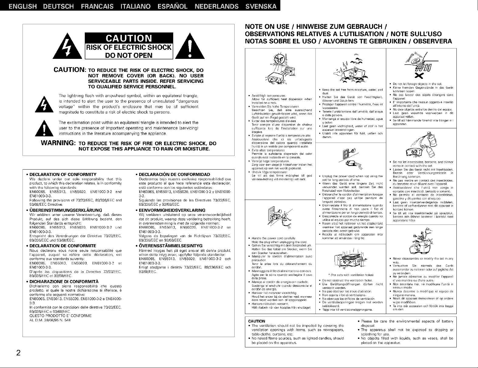
NOTE ON USE / HINWEISE ZUM GEBRAUCH /
OBSERVATIONS RELATIVES A L'UTILISATION / NOTE SULL'USO
NOTAS SOBRE EL USO / ALVORENS TE GEBRUlKEN / OBSERVERA
• Do r_ot et foreign objects n the set
• Keep tie set free from moisture wate and
• Avoid h@h temperatures
Allow for sufficient heat dispersion when
_nst_lled on a rack
• Verme_den S_e hohe _mperatu_en
Beachten S_e. da_ e_ne aus_e_chend
Luftzirkulabor_ gew_hr_eistet w;_ _nn das
Ger_t auf eir_ Rega_ geste_lt wird
• £viter des temperatures _levees
Teni_ compte dune dispersion de chaleur
suff_sante Iors de Ims_al_ation sur une
_t_g_re
• £vitate di es#or re _ur_i_ a _emperature a_te
Ass_curatev] the ci sia unadegua_a
d;spersione del ca_ore quando msla_ate
_ur_i_ in un mobile per componenti audio
• £vi_e a_tas tempera_UFaS
PermUte k_ suf_ciente dispers_6n de_ taro{
cuando es_4 instak_do en la consola
• Vermijd ho_ _emperatu_n
Zorg voor een de_lijk hit_ea fvoer _ndien het
apparaat op een _k wordt gep_aats_
• Undvik h6_ tempe_am_er
Se 1i_1 a_ det finns m6}lighet till god
v_r meavledning rid r.ontering _et_ rack
• Handle the power Cord caretu ly
HoFd the plug when unpfugg ng the cord
• Gehen Sie vorsichtig mit dem Ne_zkabel um
HaSten Sie das Kabel am Stecke_ wenn Sie
den Stecker herausziehen
• Manipuler _e co,on dalimentation avec
p_cau_ion
Teni_ k_ _rise Io_s du d6branchement du
cordon
• Manne_Niate i_ f_o di a_;mentazior_e con cura
Agke per la spina quando sco_le_e il cavo
dalk_ p_sa
• M_neje el cordon de ener_ con Cu_dado
Scster_ga el enchufe cuando desconec_e el
cord6n de energi_
• Han_eer het netsnoe_ vocrz_chtig
Houd her snoer bi i de stekker vest wanneer
deze moet .0_rder_ aan of _osgekoppeld
• Han_era na_kabelr_ varsamt
H_ i kabe_n n_r den kopp_as fr_r_ el ut_age_
CAUTION • P_ease be care the environmental aspects of battery
• The ventilation should not be impeded by covering the disposal
ventilation openings with items, such as newspapers, • The apparatus shall not be exposed to dripping or
tablecloths, curtains, etc sbjashJng for use
• No naked flame sources, such as lighted candles, should • No objects filled with ]iqulds, such as vases, shal_ be
dust
• Halten Sie das Ge_t yon Feuchtigkei,
Wasse_ und St_ub fern
• Pro_eger lappare_ centre Ihum_dite leau et
[apoussi6re
• Tenete _unit_ _ontana da_l ur_idit& da_ acqua
e della polve_e
• Man_enga el e_uipo _ibre de humedad agua
y polvc
• Laat geen vcchtigheid water of stcf in bet
apparaat bin_endringen
• Uts_tt inte apparaten f@ fu_t vatten och
damm
• Unplug the power cord when rot usirg the
se_ for long _er ods o +tree
• Wenn das Ger_t eine _finge_e Zeit nich_
verwendet werden SOIL tr_nnen Sic das
Nelzk_bel vom Net_s_cker
• D_branche_ _e co,on d a_iment_tion _orsque
lappareil nest pas util_se _endant de
_or_gues pe_odes
• Disinnesta_e il filo di alimentaz_one quando
ave_e lintenzione di non usare il f_lo di
a_iment_zione per un lunge pe_iodo d_tempo
• Desconec_e e_ cor_n de energ_a cuan_ no
u t_lic_ e_ equipo por mucho t_empo
• Neem a_titd het ne_noer uit het stopkontakt
wanneer he1 apparaat gedurende een _a_ge
periode n_et wont gebruikt
• Koppla u_ n_tkabeln om apparaten inte
kommer att anv_ndas i I_ng t_d
_ (For sets with ventilation holes)
• DO not obstruct the ventilation holes
• D_e Beh4tungs_ffnur_gen dt_rfen n_cht
verdeckt werden
• Ne pas obstr uer les _rous d aeration
• Non copri_e i fori di venti_az_one
• NO obstr uya los o{ificios de vent_ac_6n
• De ventila_ieopen_ngen mogen nlet _rden
beblokkeerd
• _pp _nte _11 ve nti_atio ns6ppnrnga rna
be placed o_ the apparatus¸ bjaced on the appalatus
• Keine fremden Gegenst_de n das Gerat
kommen lassen
• Ne p_s laisser des obJets etrange_s dans
I'appareil
• E¸ important e the nessun ogg_to e inse_to
all'inter no dell umta
• No deie obJetos ex_a_os den_ del equ_po
• Laat geen vreemde voo_we_pen m d_
appa_aa_ vallen
• Se till art fr_mmande f_rem_ _n_e trfinge_ ir__
apparaten
• Do not let insecticides¸ benzene¸ and thinner
come in contac_ with _he se_
Benzin oder VerdQr_r_ungsmitte_n _r_
BerOhrung kummen
• Ne _as r_e!tre en coatact des insecticides
du benzene et n duan¢ avec I apparei
• Assiouralevv ohe rit_ non veaga n
conta tu cor_ insert c d ber zolo o soiver_t
• NO permita el con€acre de msectci_as
gase na y d uyer_tes con e equipo
• Laat geer_ insekter_verdegerde middeler.
benzn e o' velfverdunne met dit apparaat ir_
kontakt komen
• Se t art irate nsektsmedel p5 sprayb{uk.
benser och _hnner _un_me _kontakt reed
apparatens h61je
• Neve_ disassemble or modify _he set _n any
way
• Versuchen Se niemafs das Ger&
ause nander zu nehmen ode auf iegliche A_t
zu ver_ndem
• Ne iamas demoate ou modifier lappare
dune r_ni_re ou dune a_t_
• Non smonta e mai re modficate uni@ in
nessur_ r_odo
• Nunca desarme O modifique e equ_po de
n]ngur _ r_anera
• Noot dit apparaat demonteren of o£ andere
wijze m_/Jif @en
• _a nte is_r apparaten c,ch f6rs6k nte bygga
om den
Page 3
• We greatly appreciate your purchase of the AVR-2803.
• To he sure you take maximum advantage of all the features the AVR*2803 has to offer, read these
instructions carefully and use the set properly. Be sure to keep this manual for future reference,
should any questions or problems arise.
"SERIAL NO.
PLEASE RECORD UNIT SERIAL NUMBER ATTACHED TO THE REAR OF THE
CABINET FOR FUTURE REFERENCE"
• INTRODUCTION
Thank you for choosing the DENON AVR-2803 Digital Surround AV receiver This remarkable component has
been engineered to provide superb surround sound listening with home theater sources such as DVD, as well as
providing outstanding high fidelity reproduction of your favorite music sources
As this product is provided with an immense array of features, we recommend that before you begin hookup and
operation that, ou review the contents of this manual before proceeding
TABLE OF CONTENTS
[._i] Before Using ........................................................ 3
_ Cautions on Installation ........................................ 3
Cautions on Handling ........................................... 3
Features ............................................................... 4
®Connections ..................................................... 4+8
Part Names and Functions .............................. 8, 9
Setting up the System .................................. 9-17
Remote Control Unit ................................... 17+22
Operation ..................................................... 22-27
[_ Surround ...................................................... 27-31
DSP Surround Simulation ............................ 31 +34
Listening to the Radio ................................. 35+38
Last Function Memory ....................................... 38
Initialization of the Microprocessor .................... 38
Troubleshooting ........................................... 38, 39
Additional Information ................................. 39+44
Specifications ..................................................... 45
• ACCESSORIES
Check that the following parts are included in addition to the main unit:
[] BEFORE USING
Pay attention to the following before using this
unit:
• Moving the set
TO prevent shot[ circuits or damaged wires in the
connection cords, always unplug the power cord
and disconnect the connection cords between 811
other audio components when moving the set
• Before turning the power switch on
Check once again that all connections are proper
and that there are not problems with the connection
cords¸ Always set the power switch to the standby
position before connecting and disconnecting
connection cords¸
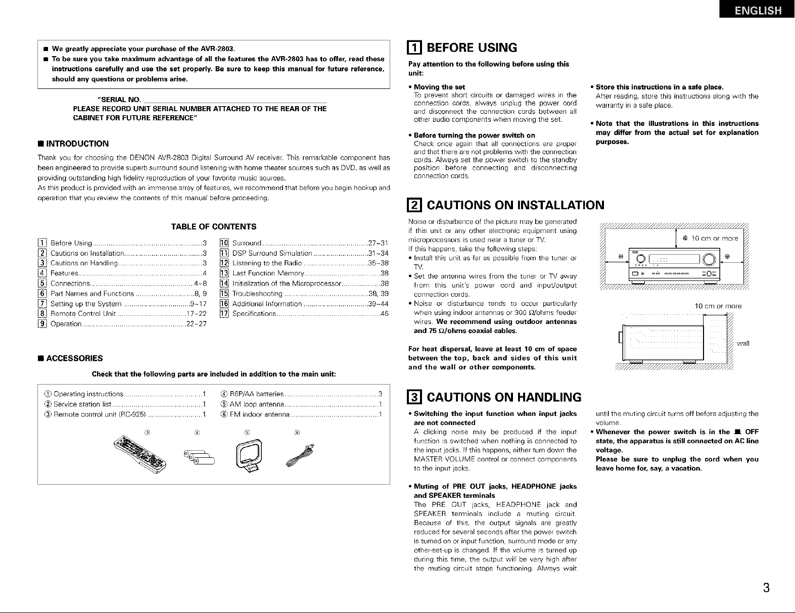
[] CAUTIONS ON INSTALLATION
Noise or disturbance of the picture may be gene+ated
if this unit or any other electronic equipment using
microprocessors is used near a tuner or TV
If this happens, take the following steps:
• Install this unit as far as possible from the tuner or
TV
• Set the antenna wires from the tuner or TV away
from this unit's power cord and input/output
connection cords
• Noise or disturbance tends to occur particularly
when using indoor antennas or 300 _Johms feeder
wires We recommend using outdoor antennas
and 75 £_/ohms coaxial cables.
For heat dispersal, leave at least 10 cm of space
between the top, back and sides of this unit
and the wall or other components,
• Store this instructions in a safe place.
After reading, store this instructions along with the
warranty in a safe place¸
• Note that the illustrations in this instructions
may differ from the actual set for explanation
purposes.
10 cm or more
wall
_ Operating instructions ........................................ 1
_2_Service station list .............................................. 1
(.3_Remote control unit (RC-925) ............................ 1
@ 14: t_; ®
_}R6P/AAbatteries ................................................ 3
®AMIoop antenna ................................................ I
_FM indoorantenna ............................................. I
[] CAUTIONS ON HANDLING
• Switching the input function when input jacks
are not connected
A clicking no_se may be produced if the input
function is switched when nothing is connected to
the input iacks If this happens, either turn down the
MASTER VOLUME control or connect components
to tile input iacks
• Muting of PRE OUT jacks, HEADPHONE jacks
and SPEAKER terminals
The PRE OUT iacks, HEADPHONE jack and
SPEAKER terminals include a muting circuit
Because of this, the output signals are greatly
reduced for several seconds after the power switch
is turned on or input function, surround mode or any
other-set-up is changed If the volume is turned up
during this time, the output will be very high after
the muting circuit stops functioning Always wait
until the muting circuit turns off before adjusting the
volume
• Whenever the power switch is in the J[ OFF
state, the apparatus is still connected on AC line
voltage
Please be sure to unplug the cord when you
leave home for, say, a vacation.
3
Page 4
[] FEATURES
1. Digital Surround Sound Decoding
Featuring 32 bit high speed DSP, operating entirely
_n digital domain, surround sound from digital
sources such as DVD, LD, DTV and satellite are
faithfully re-created
2. DTS 96/24 compatibility
The AVR-2903 can be decoded with sources
recorded in DTS 96/24, a new multi-channel digital
signal format developed by Digital Theater
Systems Inc
DTS 96/24 sources can be played in the multi-
channel mode on the AVR-2803 with high sound
quality of 96 kHz/24 bits or 882 kHz/24 bits
3. DTS-ES Extended Surround and DTS Neo:6
The AVR-2809 is compatible with DTS-ES Extended
Sunound, a new multi-channel format developed by
Digital Theater Systems Inc
The AVR-2803 is also compatible w_th DTS Neo:6, a
surround mode allowing 61-channel playback ot
regular steleo sources
4. DTS }Digital Theater Systems}
DTS provides up to 51 channels of wide-range,
high fidelity surround sound, from sources such as
laser disc, DVD and specially-encoded music
discs
5. Dolby Digital
Using advanced digital processing algorithms,
Dolby Digital provides up to 5I channels of wide-
range, high fidelity surround sound Dolby Diggal
is the default digital audio delivery system for DVD
and Nor[h American DTV
6. Dolby Pro Logic 11decoder
Dolby Pro Logic 11is a new format for playing
multi-channel audio signals that offers
_mprovements over conventional Dolby Pro Logic
It can be used to decode not only sources
recorded in Dolby Surround but also regular stereo
sources into five channels {front left/right, center
and surround left/right) In addition, vanous
parameters can be set according to the type of
source and the contents, so you can adiust the
sound field with greater precision
7. Dolby Digital EX decoder system
Dolby Digital EX is a 6 1-channel surround format
proposed by Dolby Laboratories that allows users
to enioy in their homes the "DOLBY DIGITAL
SURROUND EX" audio format iointly developed
by Dolby Labolatories and Lucas Films and first
used for the movie "Star Wars Episode 1 -
Phantom Menace"
The 61 channels of sound, including surround
back channels, provide _mproved sound
positioning and expression of space
4
8. Wide screen mode for a 7.1*channel sound
even with 5,1-channel sources
DENON has developed a wide screen mode with
a new design which recreates the effects of the
multi surround speakers in movie theaters The
result is 7 f-channel sound taking full advantage of
surround back speakers, even with Dolby Pro
Logic or Dolby Digital/DTS 5 1-channel signals
9. Multi Zone Music Entertainment System
Multi Source Function:
This unit's Multi Source function lets you select
different audio sources for listening Different
sources can thus be enjoyed in the main room
(MAIN) and the subroom {ZONE 2)
simultaneously
10 Component Video Switching
In addition to composite video and "S" video
switching, the AVR-2803 provides 2 sets of
component video (Y, PB/CB, PR/C£) inputs, and one
set of component video outputs to the television,
for superior picture quality
11, Video Select Function
Allow you to watch one source (visual) while
listening to another source (audio)
12. Future Sound Format Upgrade Capability via
Eight Channel Inputs & Outputs
For future multi-channel audio format(s), the AVR-
2803 is provided with 71 channel {seven main
channels, plus one low frequency effects channel)
inputs, along with a full set of 71 channel pro-amp
outputs, controlled by the 8 channel master
volume control This assures future upgrade
possibilities for any future muki-channel sound
format
[] CONNECTIONS
• Do not plug in the AC cord until all connections
have been completed
• Be sure to connect the left and right channels
properly {left with left, right with right)¸
• Insert the plugs securely¸ Incomplete connections
will result in the generation of noise¸
• Use the AC OUTLET for audio equipment only.
Do not use them for hair driers, utc.
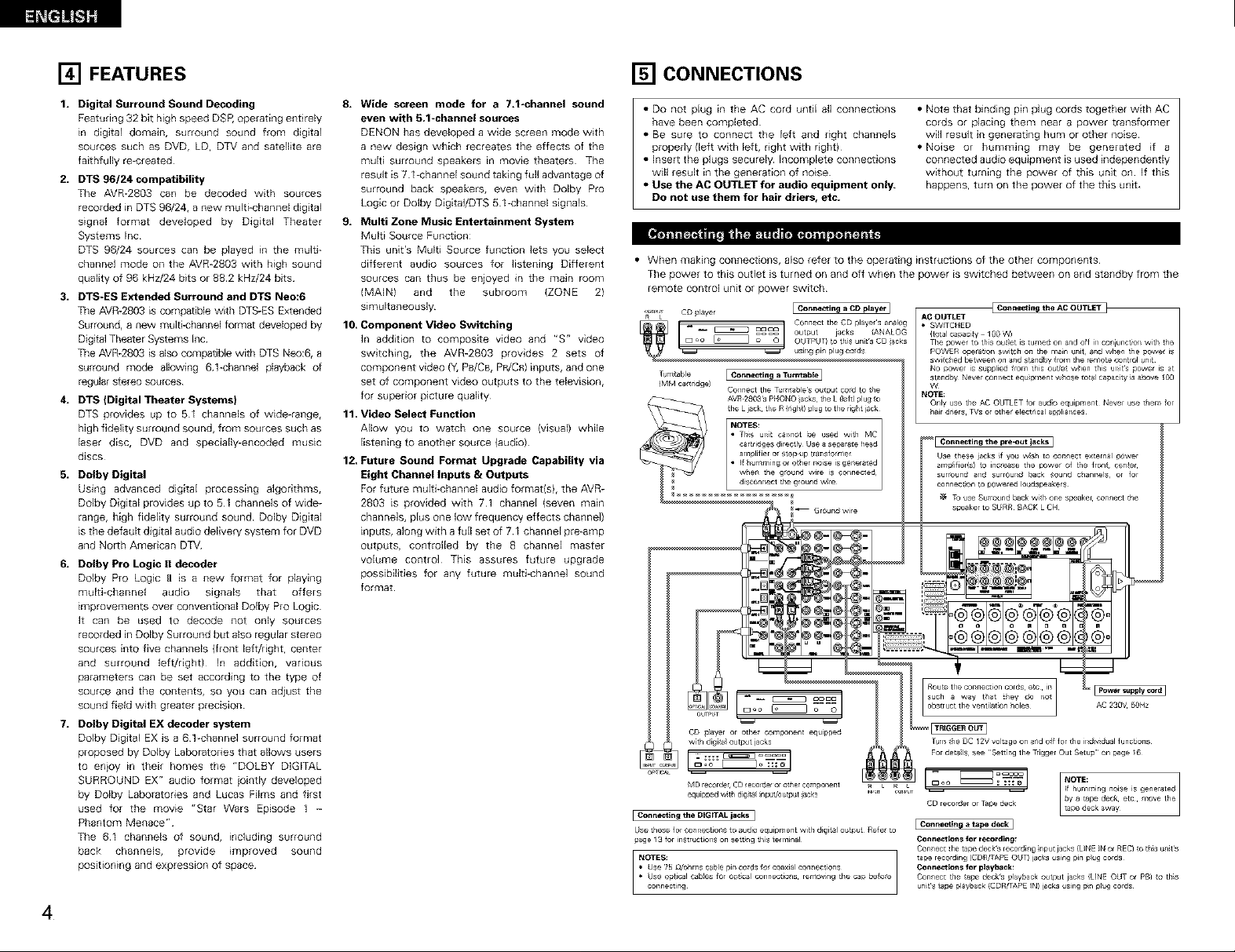
When making connections, also refer to the operating instructions of the other components
The power to this outlet is turned on and off when the power is switched between on and standby from the
remote control unit or power switch
_ I CD payer F•Connecting a CD player jq
R L
-- __ _ °aa° output jacks (ANALOG
_oo ;=21 OUTPUT) to tt sun t's CD acks
' _ using pm plug cords
Ttm table [ Connecting a Tutncable]
_MM ca_ridge)
O_TIC_L
] Connec_ng the DIGITAL iacks]
Use these for eo_r eotrons to audio equipment wi_h digital output R_le tu
page 13 for instr _ct_ns on setting this _er m_nal
NOTES:
• Use 75 _/ohms Gable pir co_ds fo coaxial connec_ons
• Use optical cables for o_;ca_ cormec_ions removing the cap before
cormec_lng
Connect the T_rn_ab_e_ output o_d to the
. Connect the CD playe s analog
• Note that binding pin plug cords together with AC
cords or placing them near a power transformer
will result in generating hum or other noise
• Noise or humming may be generated if a
connected audio equipment is used independently
without turning the power of this unit on If this
happens, turn on the power of the this unit
AC OUTLET
• SWLTCHED
_total oapacity 100 W)
The oower tO th_s out_et is _umed on @ridoff ir_coniur_et_r_ with the
POWER operat_n switch on the r_a_n _nit @rid when _he powe_ is
switched between on and standby from the remote control _nit
No p_wer is supplied from this o_t[e_ when this ur_]_s power is at
standby Never Gonnect equ_pmen_ whose to_ capacity _s above 100
W
NOTE:
Only use the AC OUTLET for audio equipment Never _se them for
hair dr_ers TVs or othe_ electrical appliances
I _nne_'_ng _ tape deck I
_nn_ns for recording:
Connect _he tape deck's recording _nput jacks (L_NE _N or REC} _o tln_s units
tape recording (CD_]TAPE OUT) iaGks using pin plug cords
_nn_tl_ns for playback:
Connect the _ape decks p_ayback output jacks (LINE OUT or PB) _o th_s
units _ape pla'C_ack (CDRFAPE IN) lacks using p_n p_ug cords
LFConnecting the AC OUTLET ]
Page 5
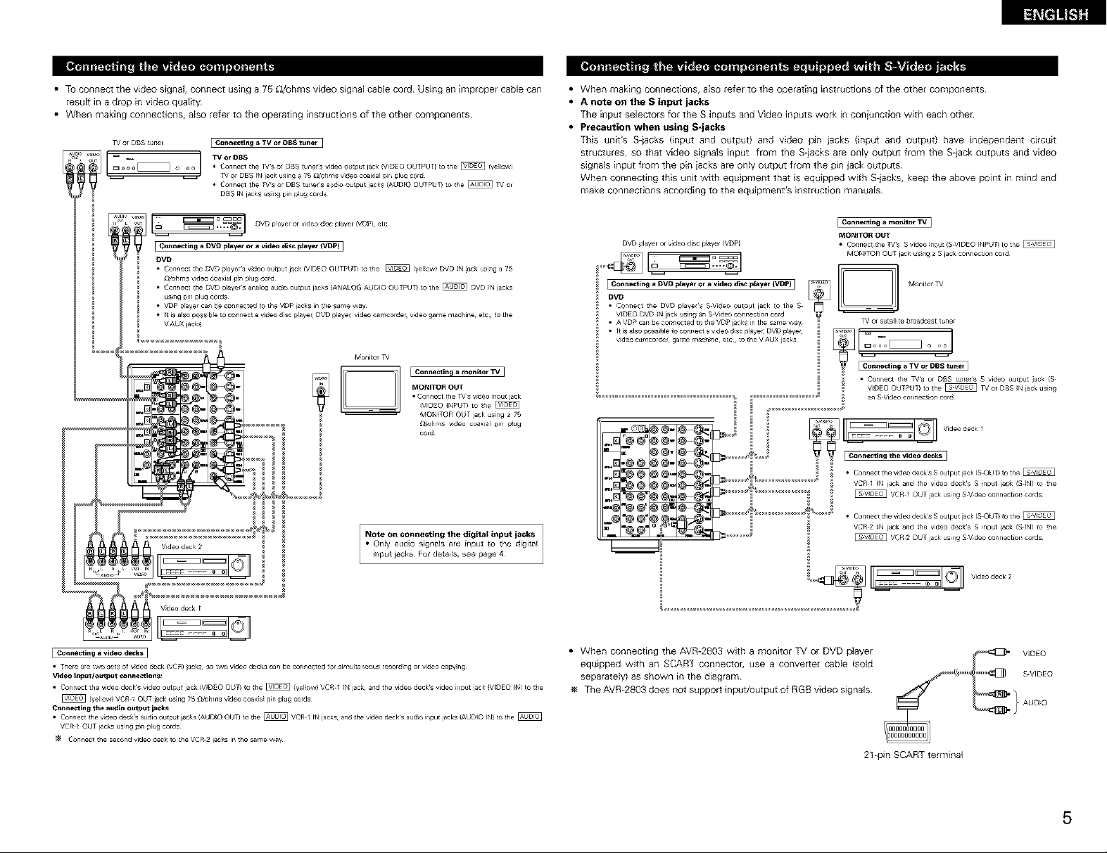
• To connect the video signal, connect using a 75 _2/ohms video signal cable cord Using an improper cable can
result in a drop in video quality¸
• When making connections, also refer to the operating instructions of the other components¸
o_ DBS tuner
___!'/:v'_/'u_' [_h_°nnectingDVD_ u* *=*_=_]a DVD p]alyet--_" _DVD player °r v_de° d sc player (VDp} ....
• Connecl tile DVD players vdeo output jack (VIDEO OUTPUT_ to tile _ (ye ow) DVD IN acl, usng a 75
O2uhms vMeo coaxial p}n plug co_d
• Connec_ the DVD playe s analog ado output jacks _ANALOG AUDIO OUTPUT) to the @ DVD IN iacks
usng pir plug cords
• VDP playe can be connected ¢o the VDP lacks n tie same way
• It s also possible tu connect a vdeo dsc play_ B DVD play_ Bvideo car£corder, v_deo garlae rlaachine, ec _o the
VAUX jacks
[ Connecting a TV or DaS tuner
TV or DB8
• Connect tile _'S o DBS cuner s vdeo output jack _VIDEO OUTPUT) to the _ (ye ow)
or DBS _N jack using a 75 _2/oflms video coaxial pin plug cord
• Connect the _Ts or DBS tune_s _udio output jacks (AUDIO OUTPUT) to the @ _ or
DBS IN jacks using pin plug cords
Monito_
MO_ITOB OUT
[_ Ec°nne_in_ _ monitor TV 1
• Connect lfle TVs vdeo nput jack
(V_DEO _NPUT) to fie
MONITOR OUT jack usng a 25
_dohrns video coaxial pin pug
cord
• When making connections, also refer to the operating instructions of the other components
• A note on the S input jacks
The input selectors for the S inputs and Video inputs work in conjunction with each other
• Precaution when using S-jacks
This unit's S-iacks (input and output) and video pin iacks (input and output) have independent circuit
structures, so that video signals input from the S-jacks are only output from the S-iack outputs and video
signals input from the pin iacks are only output from the pin jack outputs
When connecting this unit with equipment that is equipped with S-jacks, keep the above point in mind and
make connections according to the equipment's instruction manuals
Confle_ing a monito_ TV]
DVD player or v_deo disc p_ayer _VDP)
DVD
• Connect the DVD player's S Vdeo output iack to the S _ --
V_DEO DVD _N jack using an S Video connection co_d
• A VDP can be connected to tile VDP aoks n the same way _/or satellite b_oadcast _uner
v_deo camcorder game roach ne etc to the VAUX jacks _ E J o
MONITOR OUT
• Connect the ]_s S video nput (S VIDEO INPUT} to tile
MONITOR OUT jack using a S jack connection cord
• Connect _he _Ts or DBS tuners S video output ack (S
VtDEO OUTPUT) to he _ _/or DBS IN jack using
an S Video connec on Pord
I1 01oll
I_ _ @" E Connecting the video decks ]
_,__[_ _ @" _[_)_lr_'_ _ ' _ • C....... _e vdeo decks S o tp t jack (S OUT, IO the _
-_1"@®"_@__°"" ................ _ VC_l OUTjackusingSV,d......... ior,cods
Note on connecting the digital input jacks
• Only audio signals are input to the digital
J_put iacks For deta_s, see page 4
• There ae two ses of v:deo deck/VCR) acks so two v:deo decks can be connected lor simultaneous record ng or video copying
Vide,_ input/output cenne¢tions:
• Connect the vi_eo decks video outpu_ jack (V_DEO OUT} 1o lhe _ (yellow) VC_ I IN jack¸ and the video decks video input iack _VIDEO IN) to tile
(yellow) VCR 1 OUT j_ck using 7B _/ohms video coaxial pin p_ug cords
Conno¢ting the audio oulp_L ja_s
• Connect _fle video decks audio output j_c_s (AUDIO OUT) to the _ VC£ I IN jacks¸ and the vide{ deck's audio input jacks (AUDIO IN) _o _fle
VCR / OUT _acks using p_n p_ug cords
Connect the second video deck to the VCR 2 jacks in tile same wa_
"..1"_._1£ _,,_ _ _VC£2OUTjackusingSVid .........toncods
• When connecting the AVR-2803 with a monitor TV or DVD player
equipped wdh an SCART connector, use a converLer cable (sold
separately) as shown in the diagram
The AVR-2803 does not support input/output of RGB video signals
2t-pin SCART terminal
5
Page 6
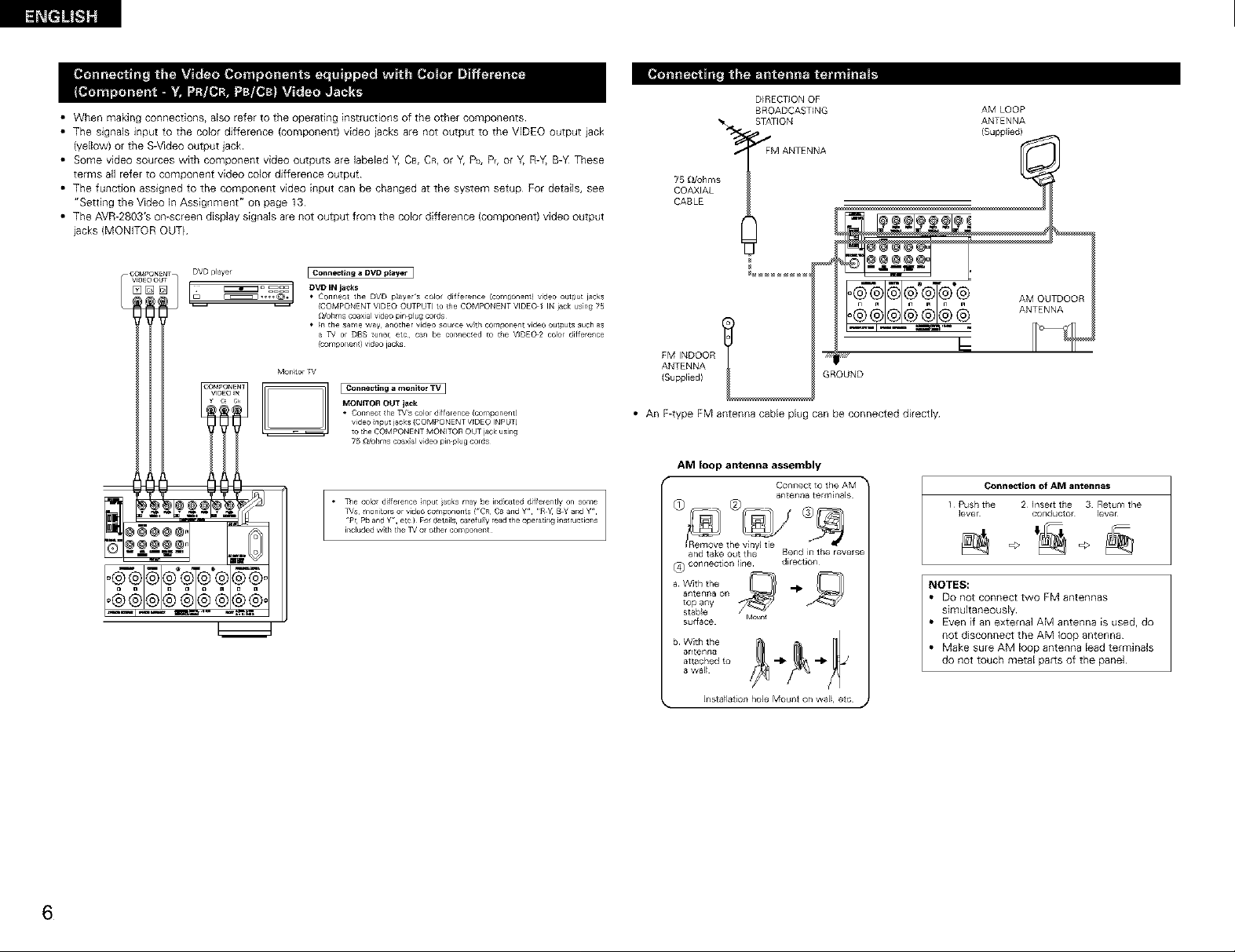
• When making connections, also refer to the operating instructions of the other components
• The signals input to the color difference (component) video iacks are not output to the VIDEO output iack
(yellow) or the S-Video output jack
• Some video sources with component video outputs are labeled Y, CB, CR, or Y, Pb, P_,or Y, R-Y, B-_ These
terms aft refer to component video color difference output
• The function assigned to the component video input can be changed at the system setup For details, see
"Setting the Video In Assignment" on page 13
• The AVR-2803'S on-screen display signals are not output from the color difference (component) video output
lacks (MONITOR OUT
I Connecting a OVD player I
[_l_ ni'l_ _'ui_-_'qlTn__
D_RECTIQNOF
BROADCASTING AM LOOP
STATION ANTENNA
75 _2/ohms I" FM ANTENNA L_
COAXIAL
CABLE
FM INDOOR "_
ANTENNA
(Supphed) GROUND
• An F4ype FM antenna cable plug can be connected directly
AM loop antenna assembly
Connect to tile AM "_
_ntenn_ terminals
{Supplied)
Connection of AM antennas
1 Push the 2 ]nselt tile 3 Retum the
]ever conductor lever
=> =>
d_rection
antenr_a on
_ W_th the _ ,,_ _
top any
_table Moor_
sulface
antenna
attached to -I_ -I_
a wal_
bWiththe _ _ _
• ]llstaHation hole Mount on wal_, etc
NOTES:
• DO not connect two FM antennas
simultaneously
• Even if an external AM antenna is used, do
not disconnect the AM loop antenna
• Make sure AM loop antenna lead terminals
do not touch metal parts of the panel
6
Page 7
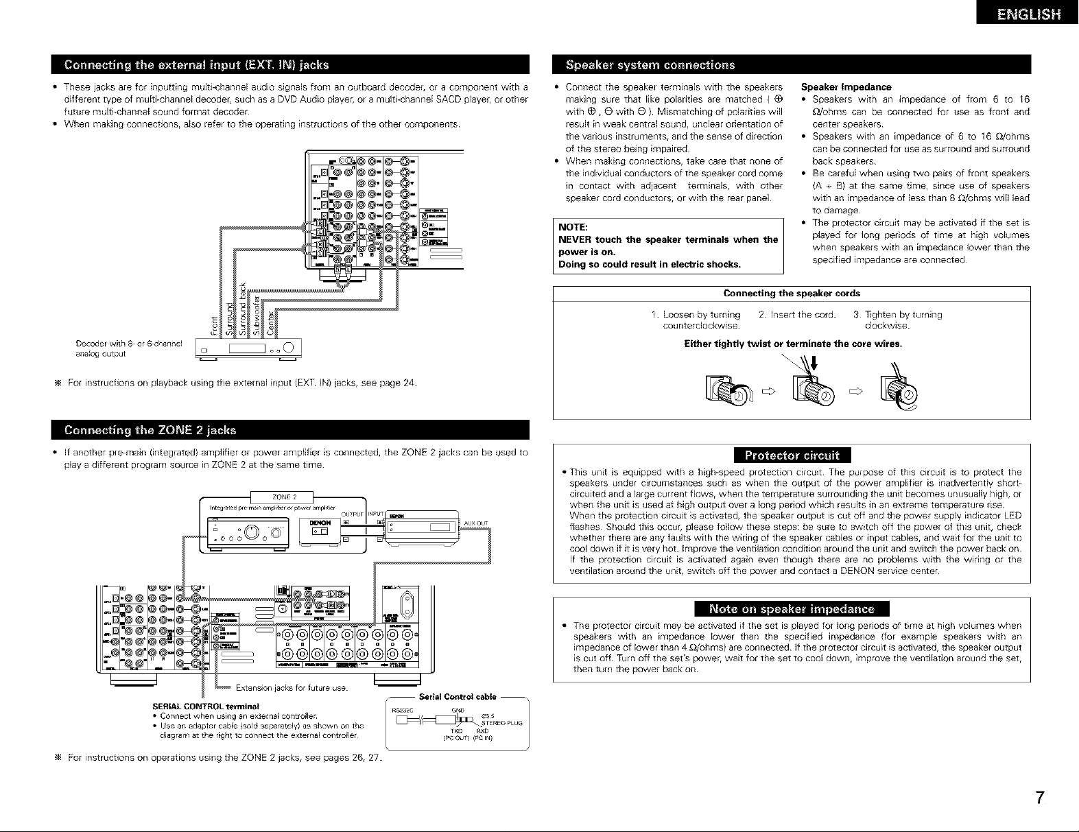
• These iacks are for inputting mugEchannel audio signals from an outboard decode_, or a component with a
different type of multi-channel decodei, such as a DVD Audio player, or a multi-channel SACD playe_, or other
future multi-channel sound format decoder
• When making connections, also refer to the opelating instructions of the other components
.[]C@@°@@-_-
@@-e4#-
Decoder with 8 or 6,_'hannel
ar_aJogoutput
For instructions on playback using the external input (EXT IN) iacks, see page 24
• If another pre-main (integlated) amplifier or power amplifier is connected, the ZONE 2 jacks can be used to
play a different program source in ZONE 2 at the same time
°°21
• Connect the speaker terminals with the speakers
making sure that like polarities are matched ( @
with @, @ with @ ) Mismatching of polarities will
result in weak central sound, unclear orientation of
the various instruments, and the sense of direction
of the stereo being impaired
• When making connections, take care that none of
the individual conductors of the speaker cord come
_n contact with adiacent terminals, with other
speaker cord conductors, or with the rear panel
NOTE:
NEVER touch the speaker terminals when the
power is on,
Doing so could result in electric shocks.
Connecting the speaker cords
1 Loosen by turning 2 Insert the cord 3 lighten by turning
counterclockwise¸ clockwise¸
Either tightly twist or terminate the core wires.
• This unit is equipped with a high-speed protection circuit The purpose of this circuit is to protect the
speakers under circumstances such as when the output of the power amplifier is inadver[ently shot[-
circuited and a large current flows, when the temperature surrounding the unit becomes unusually high, or
when the unit is used at high output over a long period which results in an extreme temperature r_se
When the protection circuit is activated, the speaker output is cut off and the power supply indicator LED
flashes Should this occur, please follow these steps: be sure to switch off the power of this unit, check
whether there are any faults with the wiring of the speaker cables or input cables, and waif for the unit to
cool down if it is very hot Improve the ventilation condition around the unit and switch the power back on
If the protection circuit is activated again even though there are no p_oblems with the wiring or the
ventilation around the unit, switch off the power and contact a DENON service center
Speaker Impedance
• Speakers with an impedance of from 6 to I6
_ohms can be connected for use as front and
center speakers¸
• Speakers with an impedance of 6 to 16 _/ohms
can be Connected for use as surround and surround
back speakers¸
• Be careful when using two pairs of front speakers
{A + B} at the same time, since use of speakers
with an impedance of less than g _ohms will lead
to damage¸
• The protector circuit may be activated if the set _s
played for long periods of time at high volumes
when speakers with an impedance lower than the
specified impedance are connected¸
@@1@@o
Extenslo[_jacks for future use
• Connect when usi[igall external controller [_ _s_
• Use an adapter cable (sold separately)as shown onthe fxu RX_
SERIALCONTROL terminal / RS232CGN_Ic_ _
diagram atthe right to connect the external co[_troller {PCout} (Pci_)
_4 For instructions on operations using the ZONE 2 jacks, see pages 26, 27
• The protector circuit may be activated if the set is played for long periods of time at high volumes when
speakers with an impedance lower than the specified impedance (for example speakers with an
impedance of lower than 4 _hms} are connected¸ If the protector circuit is activated, the speaker output
is cut off Turn off the set's power, wait for the set to cool down, improve the ventilation around the set,
then turn the power back on
Serial Control cable --
TE_EO PLUG
7
Page 8
co,,,,e=io.s [] PART NAMES AND FUNCTIONS
• When making connections, also refer to the operating instructions of tile other components
Connection iack fol
subwoofer with built in
amplifier {super woofer),
etc
SURROUND BACK/ZONE 2 SPEAKER SYSTEMS ]
NOTES:
• TO use Surround back with one
speaker, con_ect the speaker to
SURR BACK L CH
• The settings must be changed to use
this speaker fol ZONE 2
See page 14
I_ I_i
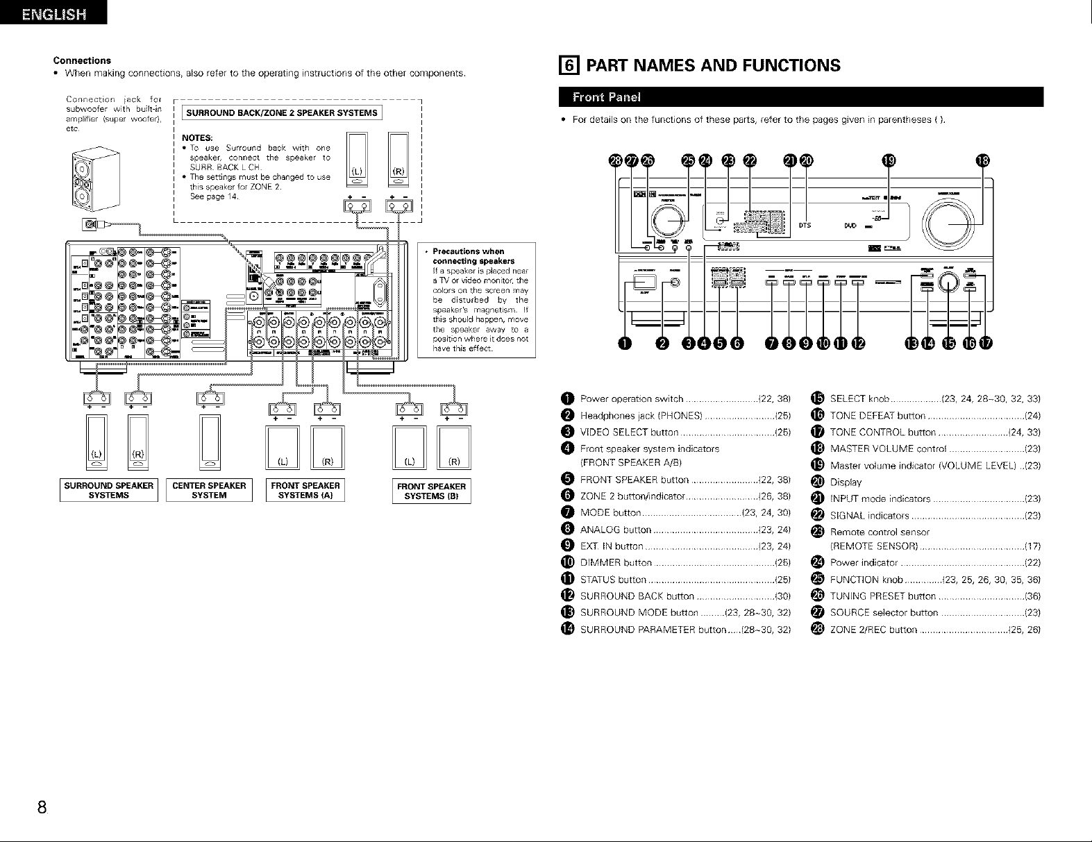
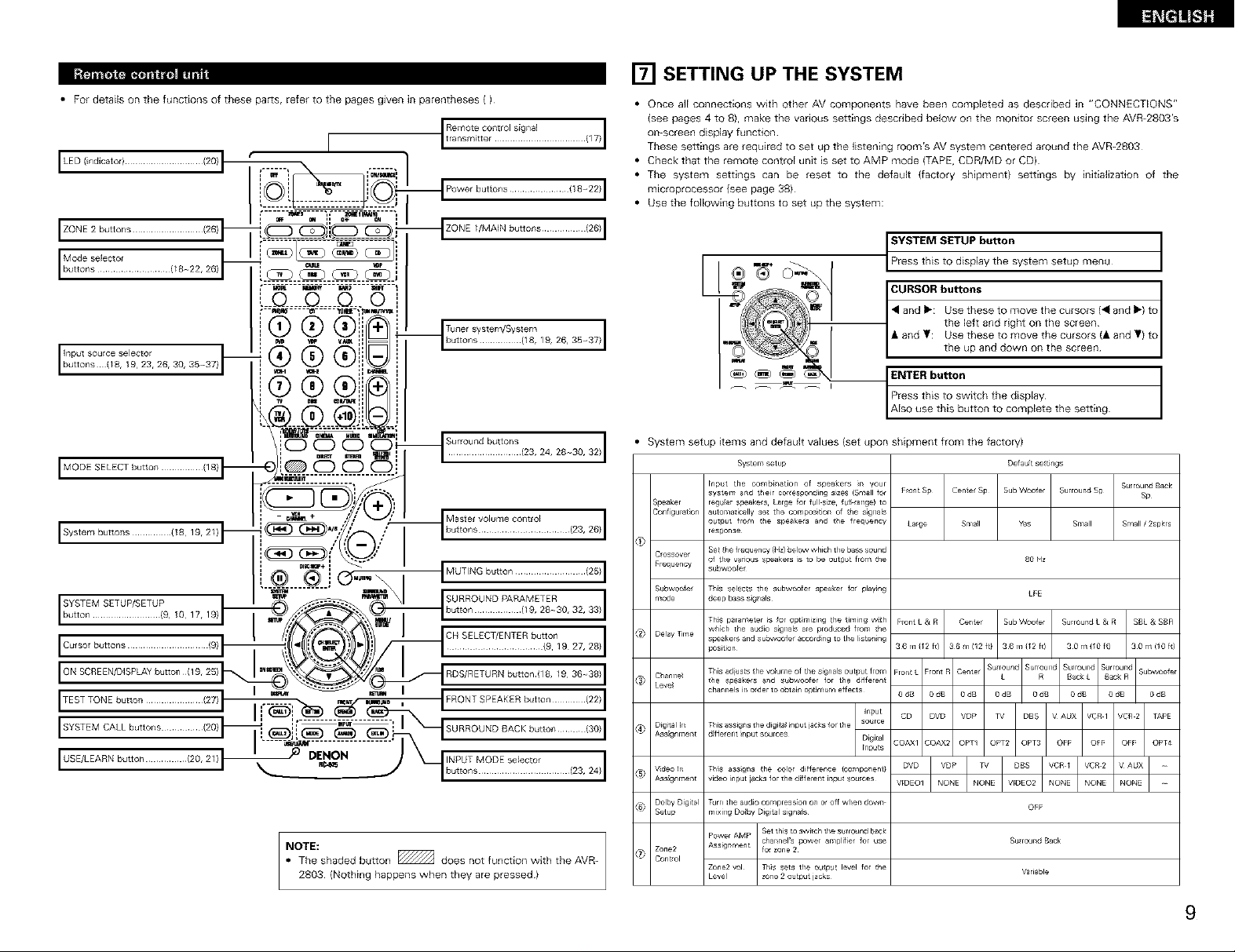
• For details on the functions of these parts, refer to the pages given in parentheses ( )
%,,,
_m®- _- ...................®@@®eee
_m,®® me- _@- _.=_
'@ @' m@_ #_@-"
SURR m AKER][CE T , m KERI I
.C
Precautions when
connecting speakers
If a speaker is placed neal
a TV ol video monitor¸ the
colors on the screen may
be disturbed by the
the speaker away to a
position where _tdoes not
have this effect
....
t_l _ i .........
_1_
Power operation switch ........................... (22, 38)
O Headphones jack ®HONESI .......................... (25)
O VEDEO SELECT button ................................... (25)
O F_ont speake_ system indicators
(FRONT SPEAKER A/B)
O FRONT SPEAKER button ......................... (22, 38)
O ZONE 2 butto®_ndicator ........................... (26, 38)
O MODE button ..................................... (23, 24, 30)
O ANALOG button ....................................... (23, 24)
O EXT IN button .......................................... (23, 24)
O DEMMER button ............................................. (25)
STATUS button ............................................... (25)
SURROUND BACK button ............................. (30)
_} SURROUND MODE button ......... (23, 28~30, 32)
SURROUND PARAMETER button (28~30, 32)
_} SELECT knob ................... (23, 24, 28~30, 32, 33)
O TONE DEFEAT button .................................... (24)
TONE C©NTR©L button .......................... (24, 33)
MASTER V©LUME control ............................ (23)
_) Master volume indicator (VOLUME LEVEL) ¸¸(23)
_ Display
_ ENPUT mode indicators .................................. (23)
_ SEGNAL indicators .......................................... (23)
_ Remote control SenSOr
(REMQTE SENSOR) ....................................... (17)
_ Power indicator .............................................. (22)
_ FUNCTION knob .............. (23, 25, 26, 30, 35, 36)
_ TUNENG PRESET button ................................ (36)
_ SOURCE selector button ............................... (23)
_ ZONE ®REC button ................................. (25, 26)
8
Page 9
• For details on the functions of these paris, refer to the pages g_ven in parentheses ( )
I
I LED (indicator)............... (20)t " IT! _l'_ [_','
I i______[1.-.----_- -._-.--- -LiQO _ P°wer butt................ {18-_22)I
,-_..______._._____........_
i [---;?_-,-;,--][--0._,-i_T--]
izo.E2butt..................,20,pb:_____ _ZONE_,MA,.bu.............,2_,i
Modeso,o0,or
ptt.................p___2,20,_____._.__.
L_Q____Q_.__Q..0
"_)-" -_- -"(_] i_ _ _t _ Tuner system,System I
_ _ ',,_ _ lbu ons 8 9 26 3B-_37
:nuPtotn_°:r_a/llgCt°3,26, 30, 35-x,7)1_ (_ (_ (_i',! --_
[] SETTING UP THE SYSTEM
• Once all connections wdh other AV components have been completed as descbbed in "CONNECTIONS"
{see pages 4 to 8}, make the various settings described below on the monitor screen using the AVR-2803's
on-screen display function
These settings are required to set up the listening room's AV system centered around the AVR-2803
• Check that the remote control unit is set to AMP mode (TAPE, CDR/MD or CD)
• The system settings can be reset to the default (factory shipment) settings by initialization of the
m_croprocessor {see page 38}
• Use the following buttons to set up the system:
_ystem setup menu I
-- the left and right on the screen
_ and I_: Use these to move the cursors (_1and I_) to
• and _: Use these to move the cursors (• and '_1to
i CURSOR buttons
the up and down on the screen
_ i
g .
\iO O O O _Surround buttons I
MODESELECTbutt ........... (18)1_ 4_)i@ O O O
' -- __2___'_:_::::::::::::.........
I SY£TEMSETUPIgETHP i -_---_ _ \1 ISURROUNDPARAMETER I
[_utto n ] [ :{9, 10 17, 19 } _ button......... g_, 28-.30, :_2, 33>I
ICutsotbutt ................. (9, I- __4_"'/ /_--ICHS[tEtT/ENT[t?u;t°n19 27,28} I
ITESTTO"Ebu,t............... RONTS EA ERbu, ........
I SYSTEMCALL buttons ........ (20}I_1 ,L__(_. _.___ .-_"_-_"___-_-2!__--I, ii i SURROUNDBACKbutton ..... (30)I
USELEARN butt ........... 20 2/ I- I _) DE_. J k INPUT MODE seecto
, , _ J -ku......................,2_,_o,I
•-- _'- _ / .............. (2:1'24'28:1°'32>1
- _ ÷ .'_.." __."." _," Master volume control
® ® i (Du'_ I ........ ,,_,
NOTE:
• The shaded button _ does not function with the A'_/R-
2803 (Nothing happens when they are pressed)
--I ENTER button
System setup items and default values (set upon shipment from the factory)
Press this to switch the display
Also use this button to complete the setting
Default se tings
80 Hz
LFE
& SBR
1 (10 ft}
0 dB
TAPE
OPT4
OFF
Su_roand Back
Variable
9
Page 10
System setup
£x_ h
Subwoofer Set the Ext In Subwooter termina playback _,el
Lewl
Auto
Surround
Mode
On Screen display that apoears or_ the monkor screen when
D_spIay _hecontroIs
_lgger Out Set,he _gge_ Out outputforthe dit_erentinput
Setup souses
Auto Tuner FM s_at_ns ere _eceived automatically and stored
Prese_ in _he memory
Setup Lock
Set the Auto surround mode _unct_on
Th_s sets whether o_ nollo d}sp_y the on screen
are aperated
Set whether or no_ tc _ook the system setup
se_t_ngs so that they cannot be changed
I Default settings I
Subwo_er _ +15 dB
Auto Surround MOde _ ON
On Screen Display _ ON
AI A8 875/891/981/1080/901/gol/gOWgOIMHz
£188 522/603/999/1404/1611kHz 901 /901 MHz
C1 C8 90 I MHz
DI D8 90 I MHz
E1 E8 90 I MHz
Setup Lock _ OFF
NOTES:
• The on-screen display signals are output with priority to the S-VIDEO MONITOR OUT iack during playback
of a video component For example, if the TV monitor is connected to both the AVR-2803'S S-Video and
video monitor output jacks and signals are input to the AVR-2803 from a video source {VDP, etc) connected
to both the S-Video and video input iacks, the on-screen display signals are output with priority to the S-
Video monitor output If you wish to output the signals to the video monitor output iack, do not connect a
cord to the S-VIDEO MONITOR OUT iack (For details, see page 17)
• The AVR-2803's on-screen display function is designed for use with high resolution monitor TVs, so it may
be difficult to read small characters on TVs with small screens or low resolutions
• The setup menu is not displayed when headphones are being used
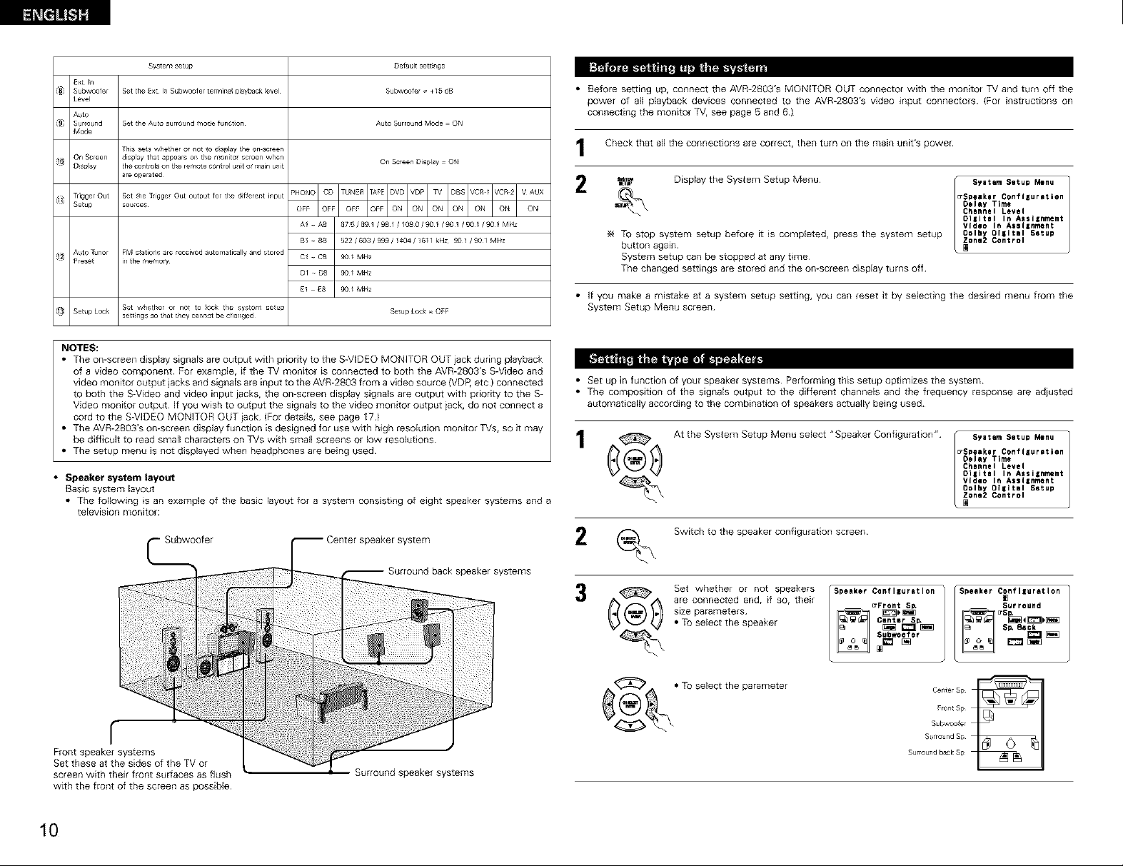
• Speaker system layout
Basic system layout
• The following _san example of the basic layout for a system consisting of eight speaker systems and a
television monitor:
• Before setting up, connect the AVR_2803'S MONITOR OUT connector with the monitor TV and turn off the
power of all playback devices connected to the AVR-2803'S video input connectors (For instructions on
connecting the monitor TV, see page 5 and 6)
Check that all the connections are correct, then turn on the main unit's power
_ Display the System Setup Menu
To stop system setup before it is completed, press the system setup
button again
Syatem Setup Menu
_Speakar Configuration
Oelay Time
Channel Level
Digital In Assilnment
Video In Assignment
0olby Digital Setup
_one2 Control
System setup can be stopped at any time
The changed settings are stored and the on-screen display turns off
• If you make a mistake at a system setup setting, you can reset it by selecting the desired menu from the
System Setup Menu screen
• Set up in function of your speaker systems Performingthissetupoptimizesthesystem
• The composition of the signals output to the different channels and the frequency response are adiusted
automatically according to the combination of speakers actually being used
At the System Setup Menu select "Speaker Configuration"
Syatem Setup Menu
_Speekar Configuration
Oelay Time
Channel Level
Oi|ital In Assignment
Video In Assignment
0olby Digital Setup
_one2 Control
woofer
r
Front speaker systems
Set these at the sides of the TV or
screen with their front sudaces as flush
with the front of the screen as possible
10
_ Center speaker system
Surround speaker systems
peeker systems
_.\ Switch to the speaker configuration screen
Set whether or not speakers
are connected and, if so, their
size parameters
e Toselectthe speaker
_(_ • TO select the parameter
Speaker Confliuratlon
_Front S_
Center S_
Subwoefer
Surround back Sp
Speaker Configuration
Surround
CenterSp
FroncSp
Subwo_er
Surround Sp
Page 11
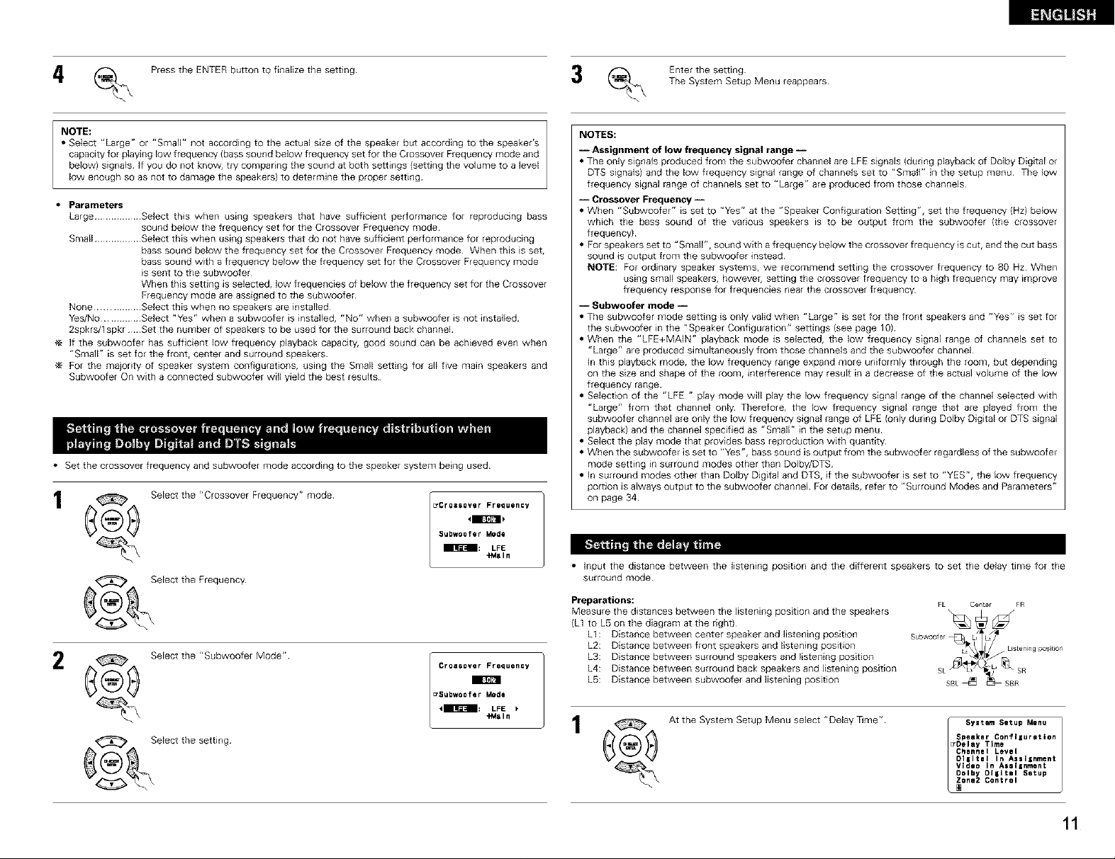
i_ (_. Press the ENTER button to finalize the setting
(_ Enter the setting
The System Setup Menu reappears
NOTE:
• Select "Large" or "SmaIF' not according to the actual size of the speaker but according to the speaker's
capacity for playing low frequency {bass sound below frequency set for the Crossover Frequency mode and
below) signals If you do not know, try comparing the sound at both settings {setting the volume to a level
low enough so as not to damage the speakers) to determine the proper setting
• Parameters
Large ................. Select this when using speakers that have sufficient performance for reproducing bass
Small ................. Select this when using speakers that do not have sufficient performance for reproducing
None ................ Select this when no speakers are installed¸
Yes/No .............. Select "Yes" when a subwoofer is installed, "No" when a subwoofer is not installed¸
2spkrs/t spkr Set the number of speakers to be used for the surround back channel¸
If the subwoofer has sufficient low frequency playback capacity, good sound can be achieved even when
"Small" is set for the front, center and surround speakers¸
For the majority of speaker system configurations, using the Small setting for all five main speakers and
Subwoofer On with a connected subwoofer will yield the best results¸
• Set the crossover frequency and subwoofer mode according to the speaker system being used
_,,_ Selectthe"CrossoverFrequency" mode
sound below the frequency set for the Crossover Frequency mode¸
bass sound below the frequency set for the Crossover Frequency mode¸ When this is set,
bass sound with a frequency below the frequency set for the Crossover Frequency mode
is sent to the subwoofer
When this setting is selected, low frequencies of below the frequency set for the Crossover
Frequency mode are assigned to the subwoofer
Subweo fer Mode
[7Cr ca e0ve r Frequency
mml_.lm: LFE
+Main
NOTES:
-- Assignment of low frequency signal range --
• The only signals produced from the subwoofer channel are LFE signals (during playback of Dolby Digital or
DTS signals) and the low frequency signal range of channels set to "Small" in the setup menu¸ The low
frequency signal range of channels set to "Large" are produced from those channels¸
-- Crossover Frequency --
• When "Subwoofer" is set to "Yes" at the "Speaker Configuration Setting", set the frequency (Hz) below
which the bass sound of the various speakers is to be output from the subwoofer (the crossover
frequency}
• For speakers set to "Small", sound with a frequency below the crossover frequency is cut, and the cut bass
sound is output from the subwoofer instead
NOTE: For ordinary speaker systems, we recommend setting the crossover frequency to 80 Hz When
using small speakers, however, setting the crossover frequency to a high frequency may _mprove
frequency response for frequencies near the crossover frequency
-- Subwoofer mode i
= The subwoofer mode setting is only valid when "Large" is set for the front speakers and "Yes" is set for
the subwoofer in the "Speaker Coofigu_ation" settings (see page 1g)
= When the "LFE+MAIN" playback mode is selected, the low frequency signal range of channels set to
"Large" are produced simultaneously from those channels and the subwoofer channel
in this playback mode, the low frequency range expand more uniformly through the room, but depending
on the size and shape of the _oom, interference may result in a decrease of the actual volume of the low
frequency range
= Selection of the "LFE " play mode will play the low frequency signal range of the channel selected with
"Large" from that channel only Therefore, the low frequency signal _ange that are played from the
subwoofer channel are only the low frequency signal lange of LFE (only during Dolby Digital or DTS signal
playback) and the channel specified as "Small" in the setup menu
= Select the play mode that provides bass reproduction with quantity
= When the subwoofer is set to "Yes", bass sound isoutput from the subwoofer regardless of the subwoofer
mode setting in surround modes other than Dolby/DTS
= in surround modes other than Dolby Digital and DTS, if the subwoofer is set to "YES", the low frequency
portion is always output to the subwoofer channel For details, refer to "Surround Modes and Parameters"
on page 34
• Input the distance between the listening position and the different speakers to set the delay time for the
surround mode
Preparations:
Measure the distances between the listening position and the speakers
(L1 to L5 on the diagram at the right)
L1 : Distance between center speaker and listening position
L2: Distance between front speakers and listening position
L3: Distance between surround speakers and listening position
L4: Distance between surround back speakers and listening position
L5: Distance between subwoofer and listening position
FL Center FR
, I
+Main 1
At the System Setup Menu select "Delay _me"
System Setup Menu
Speaker Configuration
_Oelay Time
Channel Level
Olgltel In A/sllnment
Video In Assllnment
Oolby O[gitll Setup
one2 Control
11
Page 12
n_ _i_!
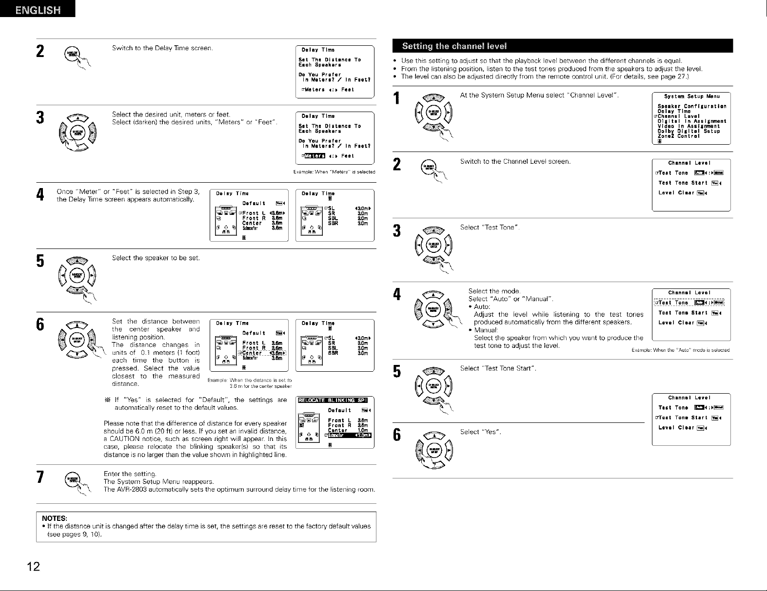
• Use this setting to adjust so that the playback level between the different channels is equal
• From the listening position, listen to the test tones produced from the speakers to adiust the level
, swtchtotheDe y mescreen[O'"T'm'
Select (darken) the desired units, "Meters" or "Feet" Sat The Distance TO
the Delay 1line screen appears automatically Default [_<
_Front L 4&Bm_
Front R &6m
,onceorFee ss ec e nStep30..,T...]o..,T.,.
Center &6m
.,,,r 3
Each Speakers
Do YOU Prefer
In Metere? / In Feet?
4:_ Feet
£xample When ¸¸Meters ¸¸ _Sselected
,,0m,
• The level can also be adiusted directly from the remote control unit (For details, see page 27 )
At the System Setup Menu select "Channel Level" System Setup Menu
Switch to the Channel Level screen
Select "Test Tone"
Speaker Conflluretlen
Delay Time
_Chennel Level
D11JteJ In Aeellnment
Video In Assignment
OoIby Diiltel Setup
one2 Control
_Teet Tone _4:_
Test Tone Start [_
Level Clearing4
J Channel Level
5 _<_4_ Select the speaker tO be set _
Set the distance between
the center speaker and
listening position
The distance changes in
units of 01 meters (1 foot)
each time the button is
pressed Select the value
closest to the measured
distance
If "Yes" is selected for "Default", the settings are
automatically reset to the default values
Please note that the difference of distance for every speaker
should be 60 m (20 ft) or less If you set an invalid distance,
a CAUTION notice, such as screen right will appean In this
case, please relocate the blinking speaker(s) so that its
distance is no larger than the value shown in highlighted line
_ Enter the setting
NOTES:
• If the distance unit is changed after the delay time is set, the settings are reset to the factory default values
(see pages 9, 10)
The System Setup Menu reappears
The AVR-2803 automatically sets the optimum surround delay time for the listening room
E×ample When ge dst_r_ce s set _o
Oefault _<
Front R 3*Q[&
Delay Time ]
_ i font L &6m
Im_fl_ &6m
3 6 _tfur the center s_eaker
Front L &am
12
Select the mode [" Channel Level
• Auto:
Adjust the level while listening to the test tones Teat Tone Start [_
produced automatically from the different speakers Level Clear [_4
Select "Auto" or "Manual" l[u'Te=t Tone _'_
• Manual:
Select the speaker from which you want to produce the
test tone to adjust the level
5
Select "Test Tone Start"
Select "Yes" j Channel Level
£xampe:When _he Autu mode is selected
Test Tone _e:_
B_raat Tone Start [_4
Level ¢lear[_
Page 13
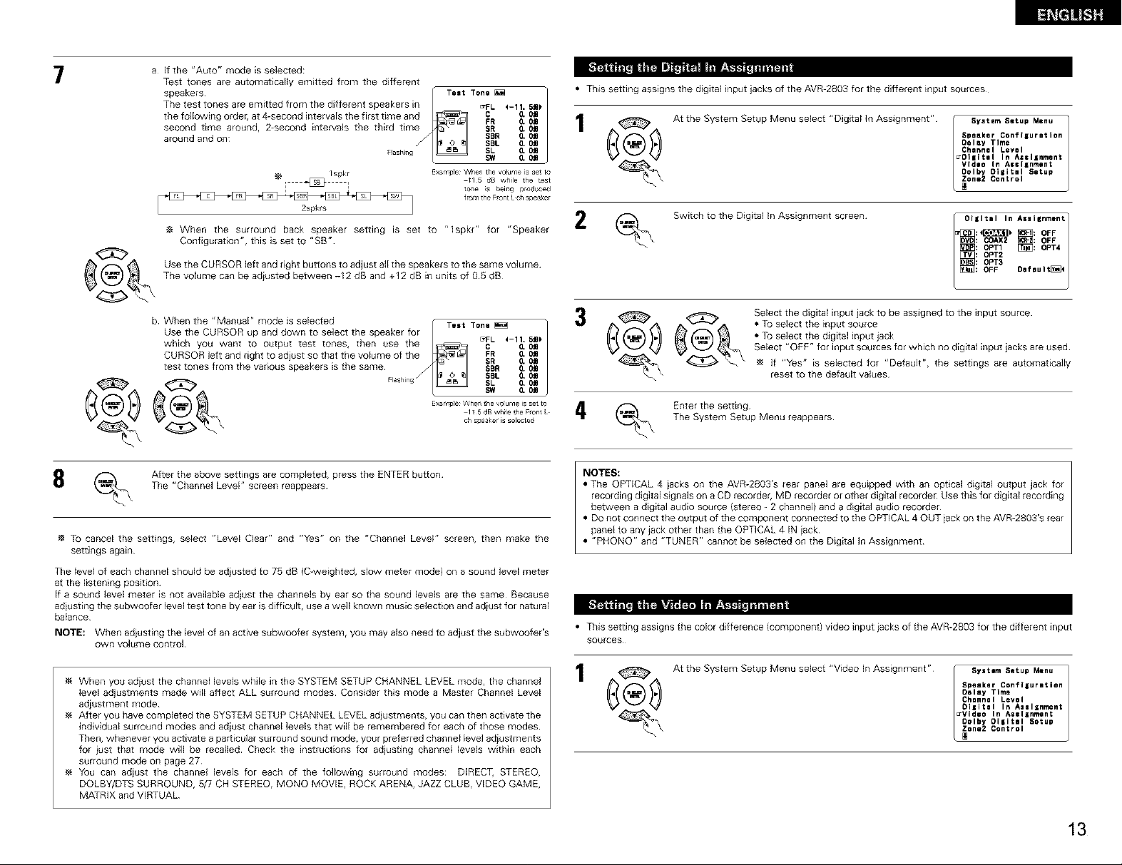
7
a If the "Auto" mode is selected:
Test tones are automatically emitted from the different
speakers / TeetTeetTone _
The test tones are emitted from the different speakers [ ErFL 4-11. Sm_
second time around, 2-second intervals the third time SR & 0a
around and on SBL & 0£
tile following order, at 4-second intervals the first time and_ FOR _ Iii
[ @ I 11 5 d8 while the test
When the surround back speaker setting is set to "1spkr" for "Speaker
Configuration", this is set to "SB"
Use the CURSOR left and right buttons to adjust all the speakers to the same volume
The volume can be adiusted between -I2 dB and +12 dB in units of 05 dB
/spkr Example When the voume is set t°
2spkls
F_ash ng SL 0, Om
®
b When the "Manual" mode is selected / TestTestTone _
Use the CURSOR up and down to select the speaker fo_
CURSOR left and right to adiust so that the volume of the FR & 0m
test tones from the venous speakers Esthe same SBR & OI
which yOU want to output test tones, then use the _ B_FI- '-1_ _1"
_ _4_ _ , Exa/I P[e _rher the v°[urlle ' ......
Flesfl_ng SL IZ O_
SBR O,0£
SW O, Om
tone $ being produced
from the F_ont L eft spea_<e r
$R & OJ
SBL & Oa
SW O*0£
11 5 dB whle tile Front L
ch speake is selected
• This setting assigns the digital input jacks of the AVR-2803 for the different input sources
/
_ At the System Setup Menu select "Digital In Assignment" f _ Syetam Setup Menu_ Spemker Conflluretien
(_ Switch to the Digital In Assignment screen
Select the digital input jack to be assigned to the input source
• To select the input source
• To select the digital input jack
Select "OFF" for input sources for which no digital input jacks are used
If "Yes" is selected for "Default", the settings are automatically
/
4 (_ Enter the setting
The System Setup Menu reappears
reset to the default values
Oelay Time
Channel Level
_Ol|ltal In As=llnment
V{dlo In A$$11nment
Oolby Oilitsl Setup
one2 Control
,°,..,.nm.n1
:4_b _1 OFF
: COAX2 : OFF
: OFF Oaf BU I till
:-1::o.o-o:o-/
_ After the above settings are completed, press the ENTER button
To cancel the settings, select "Level Clear" and "Yes" on the "Channel Level" screen, then make the
settings again
The level of each channel should be adiusted to 75 dB (C-weighted, slow meter mode) on a sound level meter
at the listening position
If a sound level meter is not available adiust the channels by ear so the sound levels are the same Because
adiusting the subwoofer level test tone by ear is difficult, use a well known music selection and adiust for natural
balance
NOTE: When adiusting the level of an active subwoofer system, you may also need to adjust the subwoofer's
own volume control
When you adiust the channel levels while in the SYSTEM SETUP CHANNEL LEVEL mode, the channel
level adjustments made will affect ALL surround modes Consider this mode a Master Channel Level
adjustment mode
After you have completed the SYSTEM SETUP CHANNEL LEVEL adjustments, you can then activate the
individual surround modes and adiust channel levels that will be remembered for each of those modes
Then, whenever you activate a par[icular surround sound mode, your preferred channel level adiustments
for iust that mode will be recalled Check the instructions for adjusting channel levels within each
surround mode on page 27
You can adjust the channel levels for each of the following surround modes: DIRECT, STEREO,
DOLBY/DTS SURROUND, 5/7 CH STEREO, MQNQ MOVIE, ROCK ARENA, JAZZ CLUB, VIDEO GAME,
MATRIX and VIRTUAL
The "Channel Level" screen reappears
NOTES:
• The OPTICAL 4 iacks on the AVR-2803'S rear panel are equipped with an optical digital output jack for
recording digital signals on a CD recorder, MD recorder or other digital recorder Use this for digital recording
between a digital audio source (stereo - 2 channel) and a digital audio recorder
• DO not connect the output of the component connected to the OPTICAL 4 OUT iack on the AVR-2803'S rear
panel to any jack other than the OPTICAL 4 IN iack
• "PHQNO" and "TUNER" cannot be selected on the Digital in Assignment
• This setting assigns the color difference (component) video input iacks of the AVR-2803 for the different input
SOUrces
At the System Setup Menu select "Video In Assignment" I_Vlde°o°lbyOIIItalChannelOelaySgeaker_ one2SYstemcontroIOi|italTImelnConf llurltienLevellnASS linmen t5etU_AisI _nmentSetupMenu
13
Page 14
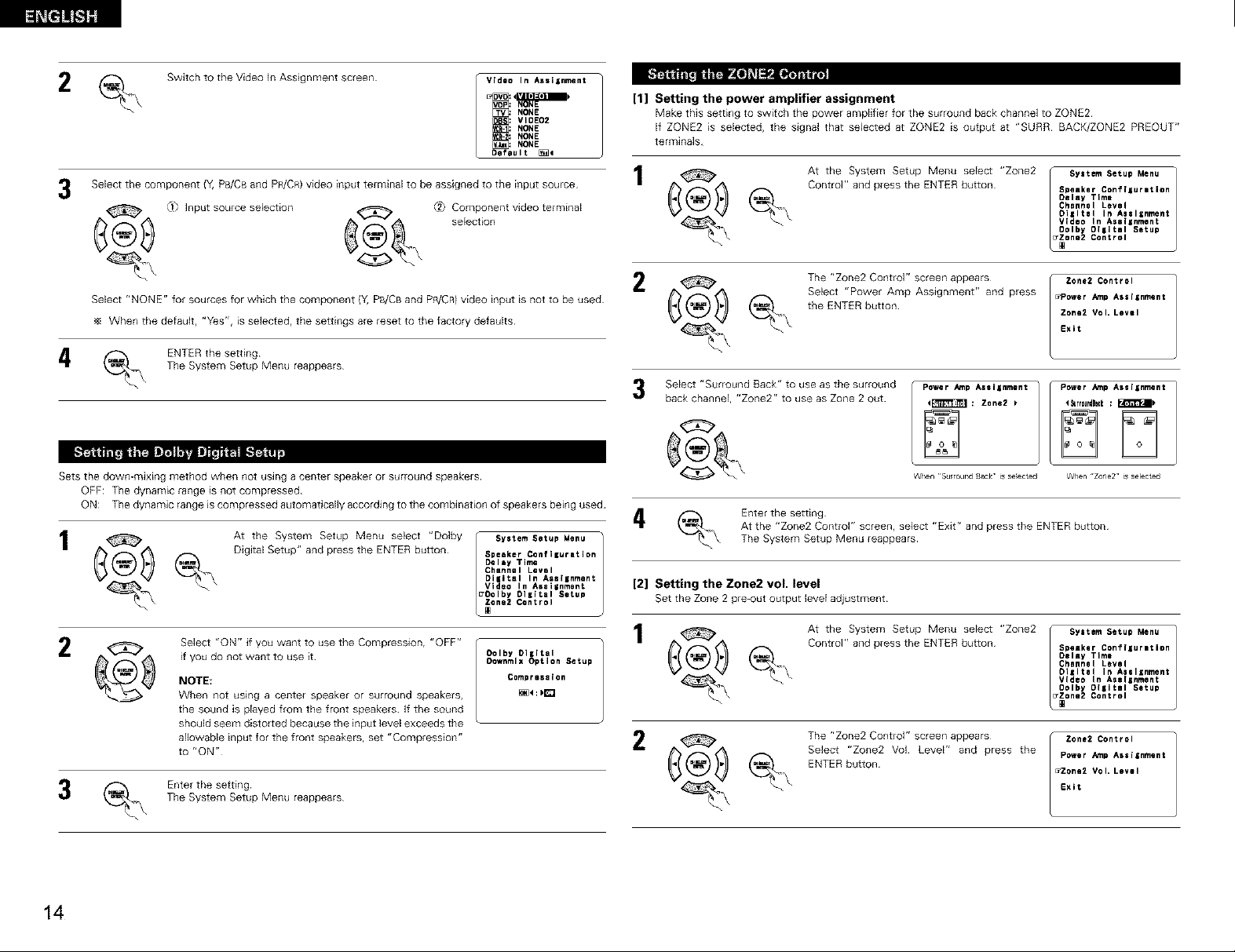
Switch to the Video In Assignment screen
Select the component {Y, PB/CB and PR/CR) video input terminal to be assigned to the input source 1 (_1
LI_ Input source selection _[_ _ Component video terminal
_4_ _ selection
Video In Assignment
NONE
NONE
Default _4
[1] Setting the power amplifier assignment
Make this setting to switch the power amplifier for the surround back channel to ZONE2
If ZONE2 is selected, the signal that selected at ZONE2 is output at "SURR BACK/ZONE2 PRE©UT"
terminals
2
Select "NONE" for sources for which the component {Y,PB/CB and PR/CRI video input is not to be used ((4/_ lb_
When the default, "Yes", is selected, the settings are reset to the factory defaults
At the System Setup Menu select "Zone2
Control" and press the ENTER button
The "Zone2 Control" screen appears
Select "Power Amp Assignment" and press
the ENTER button
System Setup Menu
Speaker Conf[gurltion
Delay Time
Channel Level
Oilltal In Assllnment
Video In Aselinment
Oolby O[lltiI Setup
one2 Control
_Power _rnp Assiinment
Zone2 Vol* Level
Exit
Zoner Control
_ ENTER the setting
The System Setup Menu reappears
HrF'4I.]':'J;l_
Sets the down-mixing method when not using a center speaker or surround speakers
OFF: The dynamic range is not compressed
ON: The dynamic range is compressed automatically according to the combination of speakers being used
_ At the System Setup Menu select "Dolby
_ _ Digital Setup" and press the ENTER button
_ Select "ON" if you want to use the Compression, "OFF"
_. Enter the setting
%
if you do not want to use it
NOTE:
When not using a center speaker or surround speakers,
the sound is played from the front speakers If the sound
should seem distorted because the input level exceeds the
allowable input for the front speakers, set "Compression"
to "ON" i. _ _'_
The System Setup Menu reappears
Speaker Confi=uretion
Delay Time
Channel Level
DiBitel In Assignment
Video In Assiinmont [2] ''*'-oez_mg
/ System Setup Menu
_Oolby Digital Setup Set the Zone 2 pre-out outputlevel adjustment
one2 Control
O01by Digital h_/_ _ Control" and press the ENTER button
Oownmlx Option Setup
Comprese[en
Select "Surround Rack" to use as the surround
back channel, "Zone2" to use as Zone 2 out
®
(_.\ Enter the setting
_ At the System Setup Menu select "Zone2
At the "Zone2 Control" screen, select "Exit" and press the ENTER button
The System Setup Menu reappears
the Zone2 voL level
The "Zone2 Control" screen appears
Select "Zone2 Vol Level" and press the
ENTER button
Power /_rnp Assignment
_rrouedgock : F,r_'_i_
WhenZone2'isselected
System Setup Menu
Speaker Conf [gurltion
Delay Time
Channel Level
Oisltal In Aeslznment
Video In Aselinment
Lz
Oolby O[lltal Setup
one2 Control
Power ._np Assignment
_Zone2 Vol* Level
Exit
Zone2 Control
14
Page 15
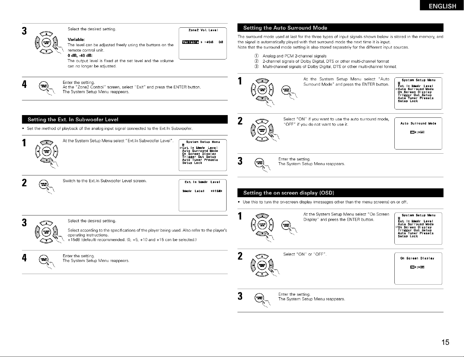
3
Select the desired setting
Variable:
The level can be adjusted freely using the buttons on the
remote control unit
Zone2 Vol+ Level
b -40d6 OdB
The surround mode used at last for the three types of input signals shown below is stored in the memory, and
the signal is automatically played with that surround mode the next time it is input
Note that the surround mode setting is also stored separately for the different input sources
0 dB, -40 dB:
Tile output level is fixed at tile set level and the volume
can no longer be adjusted
At the "Zone2 Control" screen, select "Exit" and press the ENTER button
The System Setup Menu reappears
4 _\ Enter the setting 1
_ Analog and PCM 2-channel signals
_2_ 2-channel signals of Dolby Digital, DTS or other multi-channel format
(.3_ Multi-channel signals of Dolby Digital, DTS or other multi-channel format
At the System Setup Menu select "Auto
Surround Mode" and press the ENTER button
_XL In _eflr Level
•Auto Surround Mode
Dn Screen Dlapley
Trlgler Out Setup
Auto Tuner Preeete
System Setup Menu
Setup Lock
• Set the method of playback of the analog input signal connected to the Extln Subwoofer
1
Auto Surround Mode
On Screen Display
TrlgEer Out Setup
_ u'Ext' In BULIINflrLevel
At the System Setup IVienu select "Ext hi Subw°°fer LeveF' / . sy'tem SetuP Menu 1
(_ Switch to the Extln Subwoofer Level screen
3 ,_ , Select the desired setting I
_4_ operatingSelectaccording to the specifications of the playerbeinginstructions used Also refer to the player's
+15dB (default) recommended (0, +5, +I0 and +15 can be selected)
The System Setup Menu reappears
(_.\ Enter the setting 2
Auto Tuner Presets _ f-_ Enter the setting
Setup Lock _ _ The System Setup Menu reappears
EXL In SublmferLevel
_:fgr Lebel 4+15m_
_ Select "ON" if you want to use the auto surround mode,
"OFF" if you do not want to use it
Auto Surround Mode
am __ _[[._,&_l
• Use this to turn the on-screen display (messages other than the menu screens) on or off
At the System Setup Menu select "On Screen
Display" and press the ENTER button
Select "ON" or "OFF"
EXL In _k_lfer Level
Auto Surround Mode
_On Screen Display
Trlglar Out Setup
Auto Tuner Preseta
_ System Setup Menu
Setup Lock
On Screen Display
(_ Enter the setting
The System Setup Menu reappears
15
Page 16
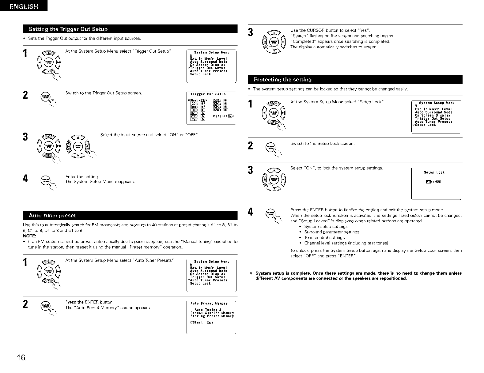
• Sets the Trigger Out output for the different input sources
1 _ At the System Setup Menu select "Trigger Out Setup"
System Setup Menu 3
_xt. In Su_fIr Level
Auto Surround Mode
On Screen DIspley
• TrlgIer Out Setup
Auto Tuner Presets
Setup Lock
Use the CURSOR button to select "Yes"
"Search" flashes on the screen and searching begins
"Completed" appears once searching is completed
The display automatically switches to screen
Switch to the Trigger Out Setup screen
_ _ Select the input source and select "ON" or "OFF"
(_ Enter the setting
Use this to automatically search for FM broadcasts and store up to 40 stations at preset channels AI to 8, B1 to
8, C1 to 8, D1 toaandEt to8
NOTE:
• ]f an FM station cannot be preset automatically due to poor reception, use the "Manual tuning" operation to
tune in the station, then preset it using the manual "Preset memory" operation
_ At the System Setup Menu select "Auto Tuner Presets"
The System Setup Menu reappears
Trilser Out Setup
Ext, In Subl_flr Level
Auto Surround Mode
On Screen Olspley
Trliger Out Setup
_Auto Tuner Presets
_ System Setup Menu
Setup Lock
• The system setup settings can be locked so that they cannot be changed easily
1 1 AttheSystemSetupMenuselect"SetupLock"
Switch to the Setup Lock screen
Select "ON", to lock the system setup settings
3®
Press the ENTER button to finalize the setting and exit the system setup mode
When the setup lock function is activated, the settings listed below cannot be changed,
and "Setup Locked" is displayed when related buttons are operated
• System setup settings
• Surround parameter settings
• Tone control settings
• Channel level settings (including test tones)
To unlock, press the System Setup button again and display the Setup Lock screen, then
select "OFF" and press "ENTER"
System setup is complete, Once these settings are made, there is no need to change them unless
different AV components are connected or the speakers are repositioned.
EXL In _k_lNr Level
Auto Surround Mode
On Screen Olsplly
Trigger Out Setup
Auto Tuner Pregetg
[] SYetam Setup Menu
Setup Lock
Setup Lock
16
Press the ENTER button
The "Auto Preset Memory" screen appears
Auto Preset Memory
Auto Tuning &
Preset Station Memory
StorlnE Preee_ MemDry
_StNrt _<
Page 17
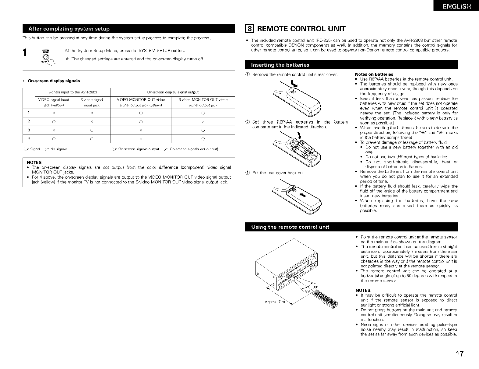
This button can be pressed at any time during the system setup process to complete the p_ocess
_ At the System Setup Menu, press the SYSTEM SETUP button
_ The changed settings are entered and the on-screen display turns off
[] REMOTE CONTROL UNIT
• The included remote control unit (RC-925) can be used to operate not only the AVR-2803 but other remote
control compatible DENON components as well In addition, the memory contains the control signals for
other remote control units, so it can be used to operate non-Denon remote control compatible products
• On-screen display signals
Signals input to the AVR 2803 On screen dJsplaVsig[lal output
VIDEO si_na_i[iput Swideo signal VIDEO MONITOR OUT video S video MONITOR OUT video
iack (yel_owl i[iput jack signal output jack {yellowl slg[la_output iack
1 × x O ©
2 © x {} ×
3 × 0 x O
4 O 0 x O
({}: Signal X: NOslglla_l (O: Orl screenslglla_soutput X: Onscleea sigrlals not output)
NOTES:
• The on-screen display signals are not output fronl the color difference (conlponent) video signal
MQN]TOR OUT jacks
• For 4 above, the on-screen display signals are output to the VIDEO MONITOR OUT video signal output
jack (yellow) if the monitor TV is not connected to the S-video MONITOR OUT video signal output jack
_) Remove the remote control unit's rear cover
_2) Set three R6P/AA batteries in the battery
compartment in the indicated direction
(.3} Put the rear cover back on
30°
Notes on Batteries
• Use R6P/AA batteries in the remote control unit
• The batteries should be replaced with new ones
approximately once a year, though this depends on
the frequency of usage¸
• Even if less than a year has passed, replace the
batteries with new ones if the set does not operate
even when the remote control unit is operated
nearby the set (The included battery is only for
verifying opeiation Replace it with a new battery as
soon as possible)
• When inserting the batteries, be sure to do so in the
proper direction, following the "@" and "@" marks
m the battery compartment
• To prevent damage or leakage of battery fluid:
• Do not use a new battery together with an old
one
• Do not use two different types of batteries
• Do not short-circuit, disassemble, heat or
dispose of batteries in flames
• Remove the batteries from the remote control unit
when you do not plan to use it for an extended
period of time
• If the battery fluid should leak, carefully wipe the
fluid off the inside of the battery compartment and
insert new batteries
• When replacing the batteries, have the new
batteries ready and insert them as quickly as
possible
• Point the remote control unit at the remote sensor
on the main unit as shown on the diagram
• The remote control unit can be used from a straight
distance of approximately 7 meters from the main
unit, but this distance will be shorter if there are
obstacles in the way or if the remote control unit is
not pointed directly at the remote sensor
• The remote control unit can be operated at a
horizontal angle of up to 30 degrees with respect to
the remote sensor
NOTES:
• It may be difficult to operate the remote control
unit if the remote sensor is exposed to direct
sunlight or strong artificial light
• Do not press buttons on the main unit and remote
control unit simultaneously Doing so may result in
malfunction
• Neon s_gns or other devices emitting pulse-type
noise nearby may result in malfunction, so keep
the set as far away from such devices as possible
17
Page 18
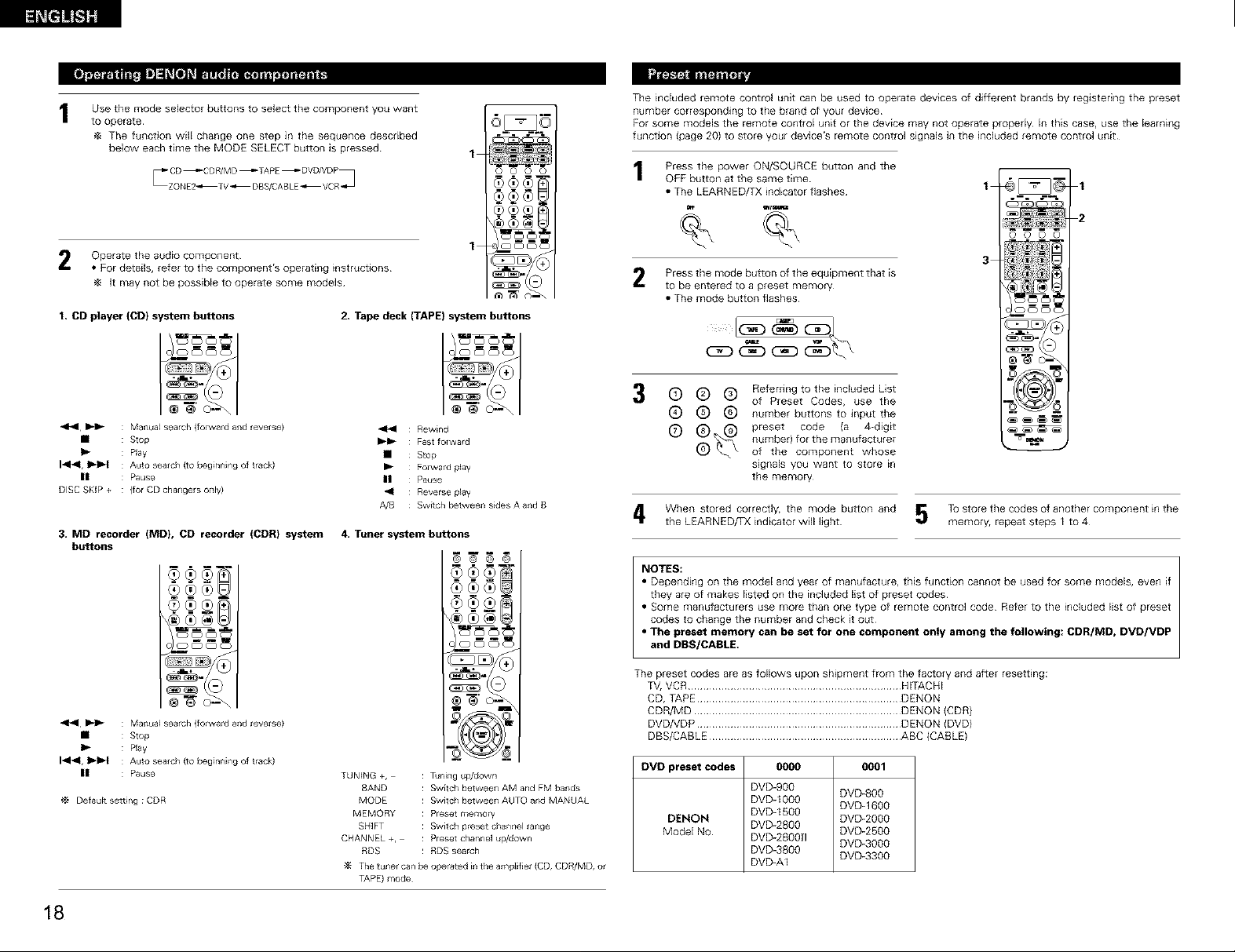
Use the mode selector buttons to select the component you want
to operate
The function will change one step in the sequence described
below each time the MODE SELECT button is pressed
The included remote control unit can be used to ope+ate devices of different brands by registering the preset
number corresponding to the brand of your device
For some models the remote control unit or the device may not operate propedy In this case, use the learning
function {page 20) to store your device's remote control signals in the included remote control unit
1
oooo
Press the power ON/SOURCE button and the
OFF button at the same time
• The LEARNED/TX indicator flashes
1
1
2 Operate the audio component
• For details, refer to the component's operating instructions
]t may not be possible to operate some models
I, CD player (CD) system buttons
_'_ : Manua_ search (folward and reverse)
• : Stop
I_ : Play
14141, _ : Auto sealch (to beginning of track)
III : Pause
DISC SKiP + : {for CD changers only)
3+ MD recorder (MD), CD recorder (CDR) system
buttons
_'_ : Manua_ search (folward and reverse)
• : Stop
I_ : Play
14141, I1_ : Auto sealch (to beginning of track)
III : Pause
Default setting : CDR
1
2, Tape deck (TAPE) system buttons
I \_ I
I®_
44 Rewind
_'1_ Fastforward
• Stop
I_ Folward play
II Pause
_1 Reverse play
A/B Switch between sidesA and B
4+Tuner system buttons
@ @ © @
TUNING +, : Tuning up/down
BAND : Switch between AM and FM bands
MODE : Switch between AUTO and MANUAL
MEMORY : Preset memory
SHIFT : Switch preset channel range
CHANNEL +, : Preset channel up/down
RDS : RDS search
The tuner can be operated in the amplifiet (CD, CDR/MD, or
TAPE) mode
3
Press the mode button of the equipment that is
to be entered to a preset memory
• The mode button flashes
© © ®
Referring to the included List
of Preset Codes, use the
® ® ® number buttons to input the
® f'8_ /'_ preset code (a 4-digit
number) for the manufacturer
of the component whose
signals you want to store _n
the memory
When stored correctly, the mode button and _ To store the codes of another component in the
the LEARNED/TX indicator will light _ memory, repeat steps I to 4
NOTES:
• Depending on the model and year of manufacture, this function cannot be used for some models, even if
they are of makes listed on the included list of preset codes
• Some manufacturers use more than one type of remote control code Refer to the included list of preset
codes to change the number and check it out
• The preset memory can be set for one component only among the following: CDR/MD, DVD/VDP
and DBS/CABLE.
The preset codes are as follows upon shipment from the factory and after resetting:
TV, VCR ...................................................................... HITACHI
CD, TAPE ................................................................... DENQN
CDR/MD .................................................................... DENON (CDR)
DVDNDP ................................................................... DENON (DVD)
DBS/CABLE ............................................................... ABC (CABLE)
DVD preset codes 0000 0001
DVD-g0o
DVD-I00O
DENON DVD 2go0
lvlodel No DVD-280OH DVD 2500
DVD-1500
DVD+2800
DVD-3800 DVD 3300
DVD-AI
DVD BOO
DVD 1600
DVD 3000
\(_) (*1) [-_
i wm m
iilqlli-m-i_,11)
m
18
Page 19
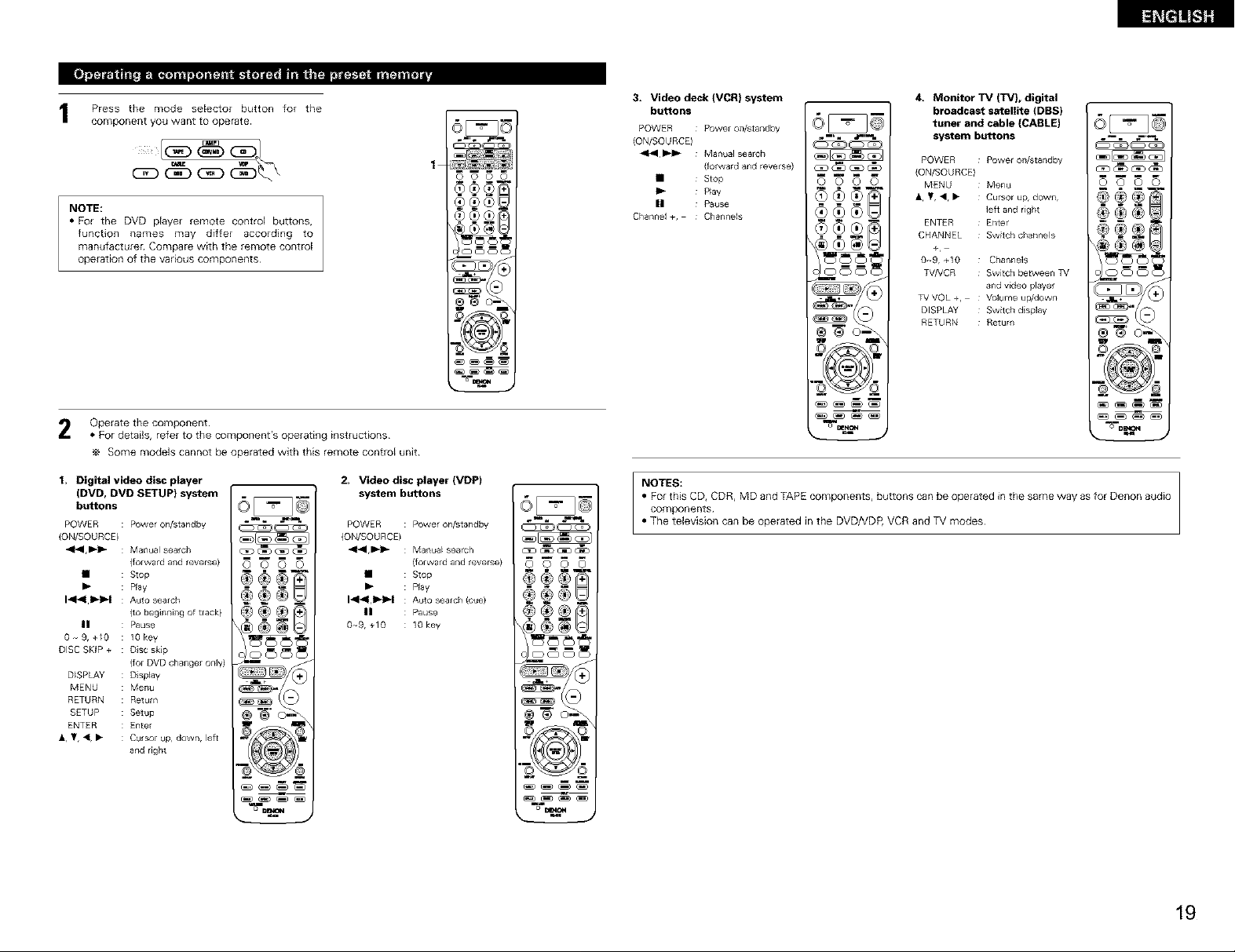
1 Press the mode selector button for the
component you want to operate
NOTE:
• For the DVD player remote control buttons,
function names may differ 8ccording to
manufacture_ Compare with the remote cont_l
operstion of the vsdous components
2 Operate the component
• For details, refer to the component's operating instructions
e Some models cannot be operated with this remote control unit
1
0 0 0 0
÷¢
3. Video deck (VCR) system
buttons
POWER : Powel on/star)dby
iON/SOURCE)
_1_1 _-1_ : Manual sealch
iforward and reverse)
• : stop
|| : Pause
Channel +, : Channels
m m m
O000
4. Monitor TV (TV), digital
broadcast satellite (DBS)
tuner and cable (CABLE)
system buttons
POWER : Power on/standby
iON/SOURCE)
MENU : Menu
• Y, <, • : Cursor up, down,
ENTER : Enter
CHANNEL : Switch channels
+
0o-9, +10 : Channels
TV/VCR : Switch between TV
TV VQL +, : Volume up/down
DISPLAY : Sw_tch display
RETURN : Return
left and r)ght
and v_deo plavel
O00O
I, Digital video disc player
(DVD, DVD SETUP) system
buttons
POWER : Power on/standby
iON/SOURCE)
"_1,1_1_ : Manual sealch
• : Stop
1414111,-I1_ : Auto search
|1 : Pause
0-_9,+/0 : lOkey
DISC SKIP + : Disc skip
D_SPLAY : DispJay
MENU : Menu
RETURN : Return
SETUP : Setup
ENTER : Enter
• , 'lr, 41,• : Cursor up, down, left
iforward and reverse)
I_ : Play
{to beglnnillg of track)
{for DVD changer only)
and nght
OOOO
2, Video disc player (VDP)
system buttons
POWER : Power on/standby
iON/SOURCE)
"_1,1_1_ : Manua_ search
• : StOp
14141,11,-I1_ : Auto search (cue)
|l : Pause
0-_9, +10 : lOkey
iforward and reverse)
I_ : P)ay
(_RZ3_
0000
o
NOTES:
• For this CD, CDR, MD and TAPE components, buttons can be operated in the same way as for Denon audio
components
• The telev)sion can be operated in the DVDNDP, VCR and TV modes
19
Page 20
ii'_l'/lln_j |_m
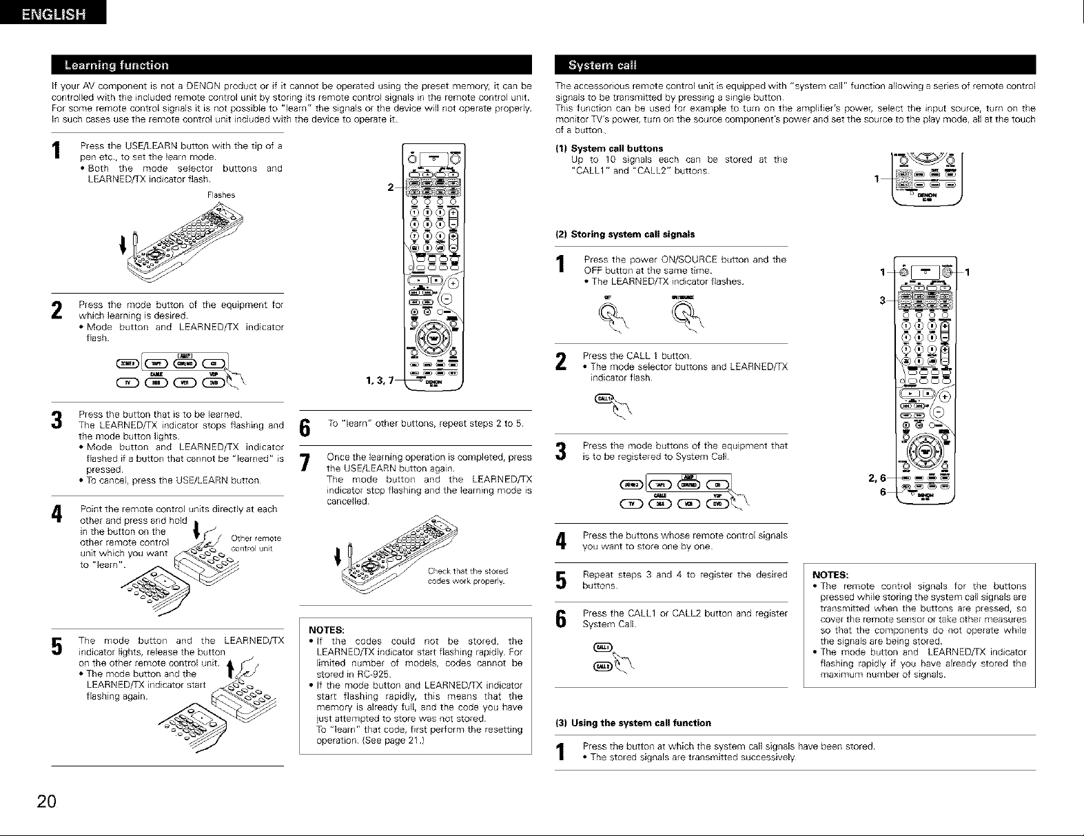
If your AV component is not a DENON product or Jf it cannot be operated Using the preset memory, Jt can be
controlled with the included remote cont@ unit by storing its remote control signals in the remote cont@ unit
For some remote cont@ signals it is not possible to "learn" the signals or the device will not operate propedy
In such cases use the remote cont@ unit included with the device to operate it
Press the USE/LEARN button with the tip of a
pen etc, to set the learn mode
• Both the mode selector buttons and
LEARNED/TX indicator flash
Flashes
Press the mode button of the eq@pment for
2
which learning is desired
• Mode button and LEARNED/TX indicator
flash
Press the button that is to be learned
3
The LEARNED/TX indicator stops flashing and
the mode button lights
• Mode button and LEARNED/TX indicator
flashed if a button that cannot be "learned" is "7
pressed
• To cancel, press the USE/LEARN button
Point the remote control units directly at each
4
other and press and hold I
Jnthe button on the i, f
other remote control v Other remote
unit which you want _ control unit
to learn __
The mode button and the LEARNED/TX
5
indicator lights, release the button
on the other remote control unit
• The mode button and the
LEARNED/TX indicator start
flashing again
To "learn" other buttons, repeat steps 2 to 5
Once the learning operation is completed, press
/
the USE/LEARN button again
The mode button and the LEARNED/TX
indicator stop flashing and the learning mode is
cancelled
NOTES:
• If the codes could not be stored, the
LEARNED/TX indicator start flashing rapidly For
limited number of models, codes cannot be
stored in RC-925
• if the mode button and LEARNED/TX indicator
start flashing rapidly, this means that the
memory is already f@l, and the code you have
iust attempted to store was not stored
To "learn" that code, first perform the resetting
operation (See page 21 )
2
O O O O
1,3,7
The accessorious remote control unit isequipped with "system call" function allowing a series of remote control
signals to be transmitted by pressing a s_ngle button
This function can be used for example to turn on the am@fier's power, select the input source, turn on the
monitor TV's power, turn on the source component's power and set the source to the play mode, all at the touch
of a button
(1) System call buttons
Up to 10 signals each can be stored at the
"CALL1 " and "CALL2" buttons
(2) Storing system call signals
Press the power ON/SOURCE button and the
OFF button at the same time
• The LEARNED/TX indicator flashes
_tE
%
Press the CALL I button
• The mode selector buttons and LEARNED/TX
indicator flash
Press the mode buttons of the equipment that
is to be registered to System Call
4 Press the buttons whose remote control signals
you want to store one by one
5 Repeat steps 3 and 4 to register the desired
buttons
Press the CALL1 or CALL2 button and register
System Call
(3) Using the system call function
Press the button at which the system call sJgn@s have been stored
• The stored signals are transmitted successively
1 _ilil _ _ &"i
1 1
.--° r,,_
_X23 _X22_
3
0 0 0 0
2,6 -_
6
NOTES:
• The remote control signals for the buttons
pressed while storing the system call signals are
transmitted when the buttons are pressed, so
cover the remote sensor or take other measures
so that the components do not operate while
the signals are being stored
• The mode button and LEARNED/TX indicator
flashing rapidly if you have ageady stored the
maximum number of signals
I
2O
Page 21
I_md_
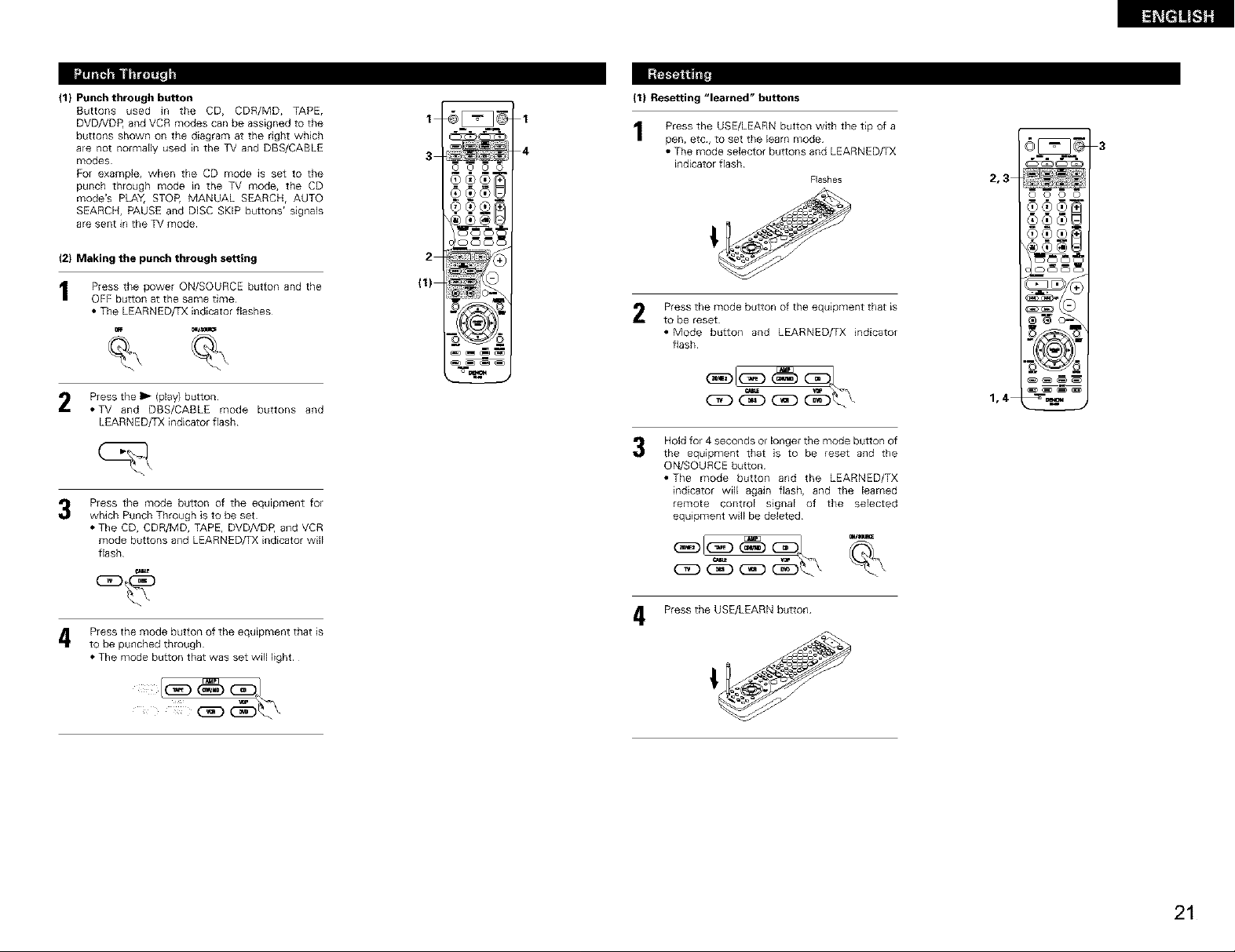
(1} Punch through button
Buttons used in the CD, CDR/MD, TAPE,
DVDNDP, and VCR modes can be assigned to the
buttons shown on the diagram at the right which
are not normally used in the TV and DBS/CABLE
modes
For example, when the CD mode is set to the
punch through mode in the TV mode, the CD
mode's PLAY, STOP, MANUAL SEARCH, AUTO
SEARCH, PAUSE and DiSC SKiP buttons' signals
are sent in the TV mode
I
3
R. ...-,%
O O O O
(1) Resetting "learned" buttons
1
4
Press the USE/LEARN button with the tip of a
pen, etc, to set the learn mode
• The mode selector buttons and LEARNED/TX
indicator flash
Flashes
3
2,3
0 0 0 0
(2} Making the punch through setting
I Press the power ON/SOURCE button and the
OFF button at the same time
• The LEARNED/TX indicator flashes
%
Press the lib (play) button
*TV and DBS/CABLE mode buttons and
LEARNED/TX indicator flash
Press the mode button of the equipment for
3
which Punch Through is to be set
• The CD, CDR/MD, TAPE, DVD/VDP, and VCR
mode buttons and LEARNED/TX indicator wHI
flash
4 Press the mode button of the equipment that is
to be punched through
• The mode button that was set will light
(1)
2
Press the mode button of the equipment that is
2
to be reset
• Mode button and LEARNED/TX indicator
flash
1,4
Hold for 4 seconds or longer the mode button of
3
the equipment that is to be reset and the
ON/SOURCE button
• The mode button and the LEARNED/TX
indicator will again flash, and the learned
remote control signal of the selected
equipment will be deleted
4 Press the USE/LEARN button
21
Page 22
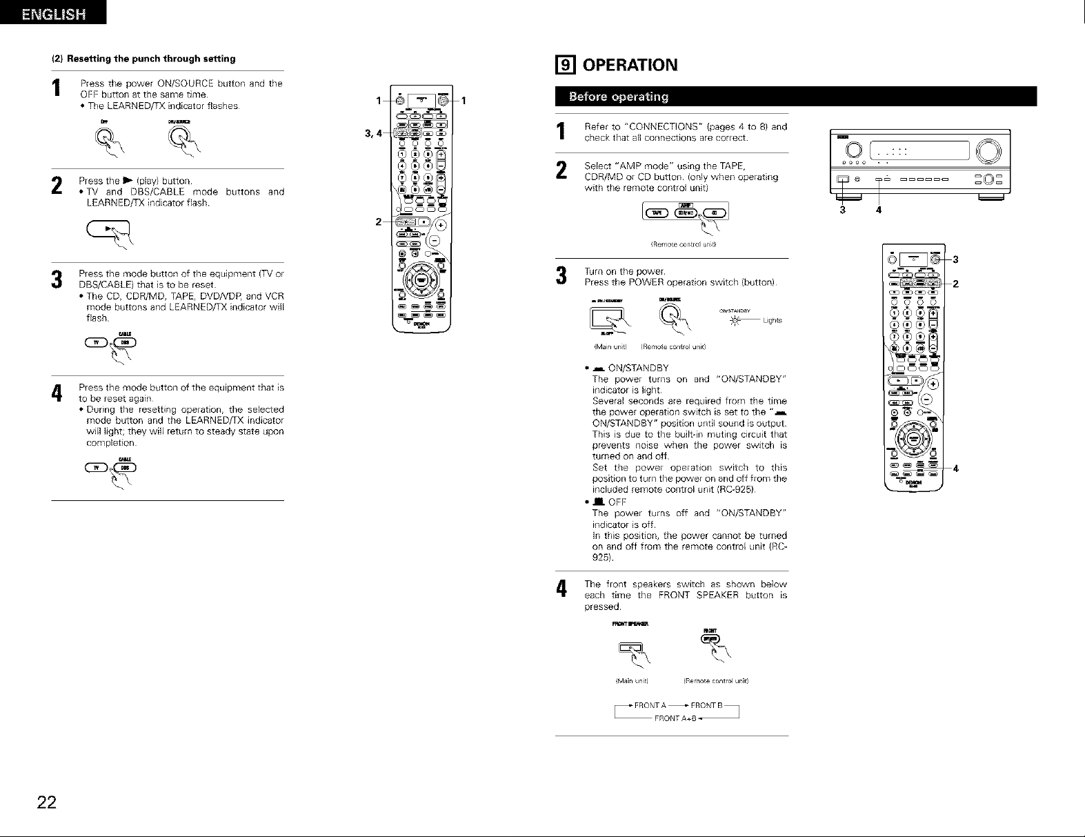
(2} Resetting the punch through setting
Press the power ON/SOURCE button and the
OFF button at the same time
• The LEARNED/TX indicator flashes
[] OPERATION
%
Press the lib (play) button
*TV and DBS/CABLE mode buttons and
LEARNED/TX indicator flash
Press the mode button of the equipment (TV or
3
DBS/CABLE) that is to be reset
• The CD, CDR/MD, TAPE, DVDNDP, and VCR
mode buttons and LEARNED/TX indicator will
flash
Press the mode button of the equipment that is
4
to be reset again
• During the resetting operation, the selected
mode button and the LEARNED/TX indicator
will light; they will return to steady state upon
completion
3,4
o o o o
®®®L
¢_0® i
Refer to "CONNECTIONS" (pages 4 to 8) and
check that all connections are correct
2 Select "AM P mode" using the TAPE,
CDR/MD or CD button {only when operating
with the remote control unit)
(Remote contro_ _t}
Turn on the power
Press the POWER operation switch (button)
_ L_gh_s
_Main unit) (Remo_e control ur_]0
• _ ON/STANDBY
The power turns on and "ON/STANDBY"
indicator is light
Several seconds are required from the time
the power operation switch is set to the "a
ON/STANDBY" position until sound is output
This is due to the built-in muting circuit that
prevents noise when the power switch _s
turned on and off
Set the power operation switch to this
position to turn the power on and off from the
included remote control unit {RC-925)
• HI OFF
The power turns off and "ON/STANDBY"
indicator is off
In this position, the power cannot be turned
on and off from the remote control unit {RC-
925)
::::
IC T
3 4
_ 2
0 0 0 0
o m_,_N
22
4, The front speakers switch as shown below
each time the FRONT SPEAKER button is
pressed
(Ma_ uni_) IRemo_e control ur_]0
FRONTA+B-
Page 23
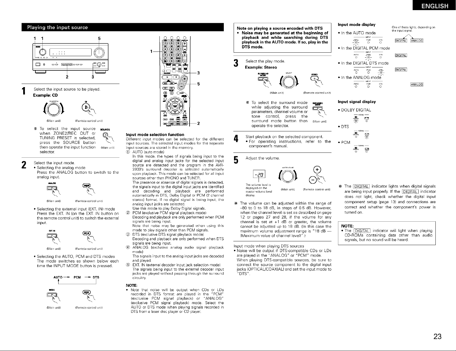
1 1 5
2 3
Select the input source to be played
Example: CD
_"N I ON CD
{Main unit} (Remote control unit}
To select the input source _u_cE
when ZONE2/REC OUT or
TUNING PRESET is selected,
press the SOURCE button
then operate the input function (Mainun]t)
selector
Select the input mode
2
• Selecting the analog mode
Press the ANALOG button to switch to the
analog input
- %
{Main unit} (Remote control unit}
• Selecting the external input (EXT IN) mode
Press the EXT IN (on the EXT IN button on
the remote control unit) to SWitch the external
input¸
• Selecting the AUTO, PCM and DTS modes
The mode switches as shown below each
time the INPUT MODE button is pressed
AUTO _ PCM _ DT S
%
{Main unit} (Remote control unit}
oooo
1
3
5
2
Input mode selection function
Different nput modes can be selected for the different
input sources¸ The selected input modes for the separate
input sources are stored in the memory¸
{1) AUTO (auto mode)
In this mode, the types of signals being input to the
digital and analog input jacks for the selected input
source are detected and the program in the AVR-
2803% surround decoder is selected automatically
upon playback This mode can be selected for all input
sources other than PHONO and TUNER
The presence or absence of digital signals s detected,
the s gnals input to the digital input iacks are identified
and decoding and playback are performed
automatically in DTS, Dolby Digital or PCM {2 channel
stereo) format If no digital signal is being input, the
analog input iacks are selected
Use this mode to play Dolby Digital signals
{2) PCM (exclusive PCM signal playback mode)
Decoding and playback are only performed when PCM
signals are being input
Note that noise may be generated when using this
mode to play signals other than PCM signals
{3) DTS (exclusive DTS signal playback mode)
Decoding and playback are only performed when DTS
signals are being input
{4) ANALOG {exclusive analog audio signal playback
mode)
The signals input to the analog input iacks are decoded
and played
{5) EXT IN (external decoder input jack selection mode)
The signals beng nput to the external decoder input
iacks are played without passing through the surround
circuitry
NOTE:
• Note that noise will be output when CDs or LDs
recorded in DTS format are played in the "PCM"
(exclusive PCM signal playback) or "ANALOG"
(exclusive PCM signal playback) mode¸ Select the
AUTO or DTS mode when playing signals recorded in
DTS from a laser disc player or CD player
Note on playing a source encoded with DTS
• Noise may be generated at the beginning of
playback and while searching during DTS
playback in the AUTO mode, If so, play in the
DTS mode,
Select the playmode
Example: Stereo
IU_ND
%
{Main unit)
To select the surround mode =_l_
while adiusting the surround
parameters, channel volume or
tone control, press the
surround mode button then _Mainunt)
operate the selector
4. Start playback on the selected component
• For operating instructions, refer to the
component's manual
Adiust the volume
Thevolumeleve{is
d}splayed on the {Main unit) (Remote control unit}
mas{e_volumeleve{
_J{spray
The volume can be adjusted within the range of
-80 toOto I8 dB, in steps of 05 dB Howeveh
when the channel level is set as described on page
12 or pages 27 and 28, if the volume for any
channel is set at +1 dB or greatek the volume
cannot be adiusted up to 18 dB (In this case the
maximum volume adiustment range is "18 dB --
(Maximum value of channel level)" )
Input mode when playing DTS sources
• Noise wi]l be output if DTS-compafible CDs or LDs
are played in the "ANALOG" or "PCM" mode
When playing DTS-compatible sources, be sure to
connect the source component to the digital input
iacks (OPTICAL/COAXlAL) and set the input mode to
"DTS"
(Remote control umt)
Input mode display
• In the AUTO mode the input signal
_ur_ _cra c_T_
@ O O
Zl\
• In the DIGITAL PCM mode
o @ o
• In the DIGITAL DTS mode
• n the ANALOG mode _
Input signal display
• DOLBY DIGITAL
• DTS
_1 _
_ro
o O
o o o
One of these lights depending on
• PCM
The _ indicator lights when digital signals
are being input propedy If the _ indicator
does not light, check whether the digital input
component setup (page I3} and connections are
correct and whether the component's power _s
turned on
NOTE:
• The _ indicator will light when @aying
CD-ROMs containing data other than audio
signals, but no sound will be heard
23
Page 24
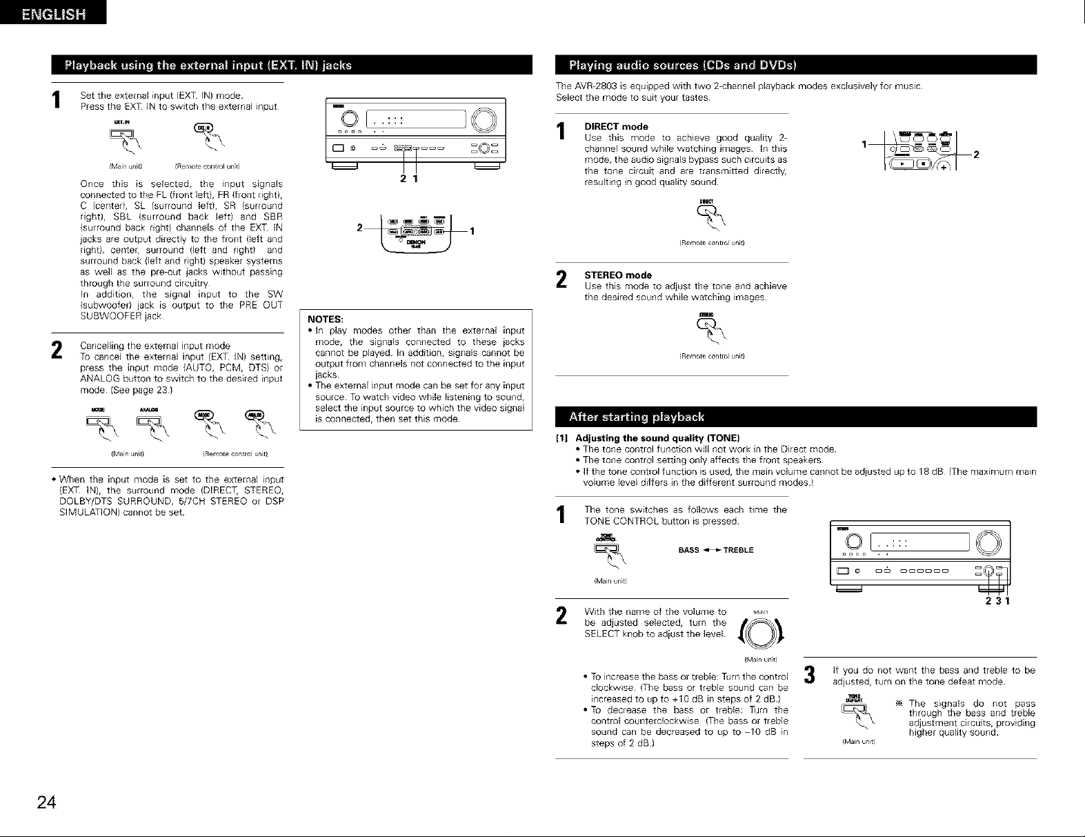
Set the external input (EXT IN) mode
Press the EXT IN to switch the external input
_'IN %
{Main unit} (Remo_e control unit)
Once this is selected, the input signals
connected to the FL {front left), FR (front right),
C (centerl, SL (surround left), SR (surround
right), SBL (surround back left) and SBR
(surround back rightl channels of the EXT IN
jacks are output directly to the front (left and
right), centel, surround (left and right) and
surround back {left and right) speaker systems
as well as the pre-out jacks without passing
through the surround circuitry
In addition, the signal input to the SW
(subwoofer) jack is output to the PRE OUT
SUBWOOFER jack
Cancelling the external input mode
2
To cancel the external input (EXT IN) setting,
press the input mode {AUTO, PCM, DTS) or
ANALOG button to switch to the desired input
mode {See page 23)
{Main unit} {Remote contro unit_
• When the input mode is set to the external input
{EXT IN), the surround mode (DIRECT, STEREO,
DQLBY/DTS SURROUND, 5/7CH STEREO or DSP
SIMULATION) cannot be set
[-9E.:::o.. :©
I
2 I
NOTES:
• In play modes other than the external input
mode, the signals connected to these iacks
cannot be played In addition, signals cannot be
output from channels not connected to the input
iacks
• The external input mode can be set for any input
source TO watch video while listening to sound,
select the input source to which the video signal
is connected, then set this mode
The AVR-2803 is equipped with two 2-channel playback modes exclusively for music
Select the mode to suit your tastes
DIRECT mode
Use this mode to achieve good quality 2-
channel sound wNle watching images In this
mode, the audio signals bypass such circuits as
the tone circuit and are transmitted directly,
resulting in good quality sound
STEREO mode
2
Use this mode to adjust the tone and achieve
the desired sound while watching _mages
_RemoLe control unit)
[1] Adjusting the sound quality (TONE)
• The tone control function will not work in the Direct mode
• The tone control setting only affects the front speakers
• If the tone control function is used, the main volume cannot be adiusted up to 18 dB (The maximum main
volume level differs in the different sunound modes)
The tone switches as follows each time the
TONE CONTROL button is pressed
24
-- :::
_Main unit)
With the name of the volume to ,,,,,,
2
be adjusted selected, turn the _
SELECT knob to adiust the level
• To increase the bass or treble: Turn the controJ
clockwise (The bass or treble sound can be
increased to up to +10 dB in steps of 2 dB)
• To decrease the bass or treble: Turn the
control counterclockwise (The bass or treble
sound can be decreased to up to -10 dB in
steps of 2 dB)
BASS _ TREBLE = • ,
IMa_n unit)
ioo
231
If you do not want the bass and treble to be
adjusted, turn on the tone defeat mode
The signals do not pass
through the bass and treble
adjustment circuits, providing
_Main unit)
higherqualitysound
Page 25
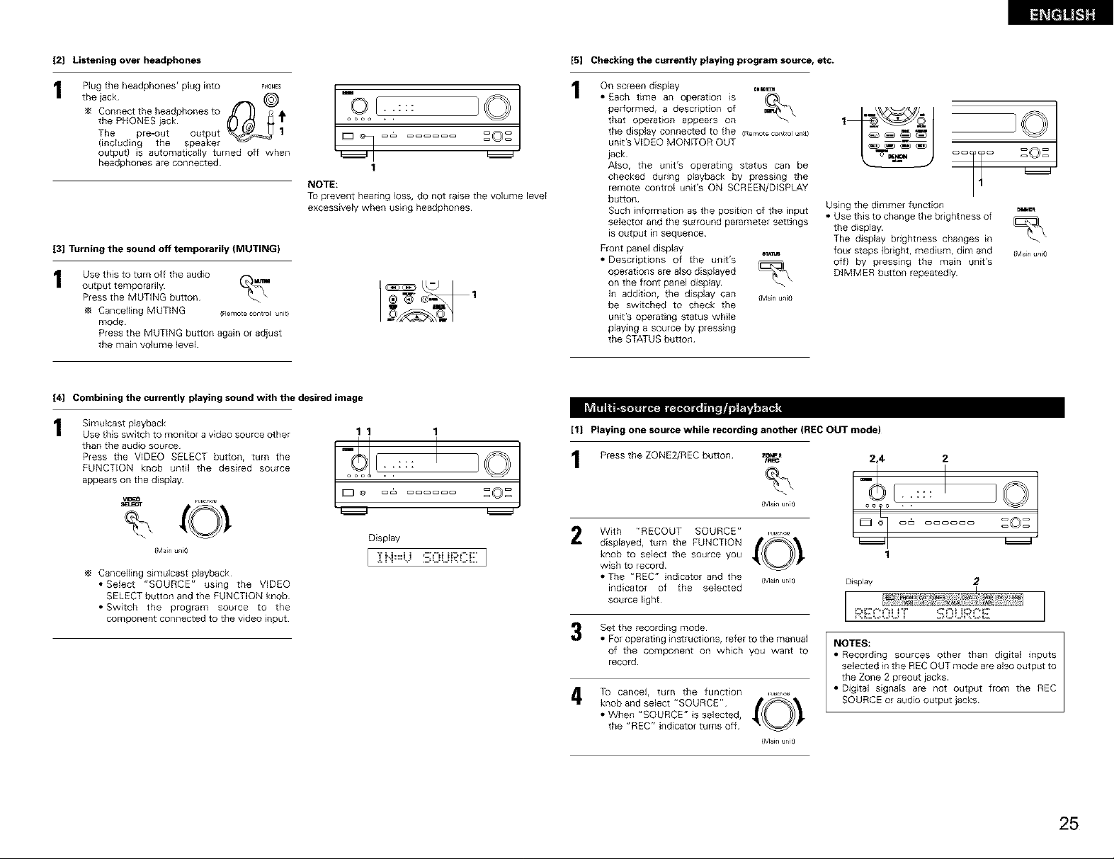
[2] Listening over headphones
the jack @
_4 Connect the headphones to f//( .J_ _ - -:::
the PHONES iack _1' o • .
The pre-out output 1 _O_
(including the speaker
output) is automatically turned off when
headphones are connected 1
NOTE:
To prevent hearing loss. do not raise the volume level
excessively when using headphones
[3] Turning the sound off temporarily (MUTING}
Use this to turn off the audio ._.
output temporarily
Press the MUTING button
Cancelling MUTING (Rerl_uecontrolunit}
mode
Press the MUTING button again or adjust
the main volume level
[4] Combining the currently playing sound with the desired image
[5] Checking the currently playing program source, etc.
On screen dispEay 0.=_
• Each time an operation is
performed, a description of
that operation appears on
the display connected to the (Remotecontrolunit)
unit's VIDEO MONITOR OUT
iack
Also. the unit's operating status can be
checked during playback by pressing the
remote control unit's ON SCREEN/DISPLAY
button
Such information as the position of the input
selector and the surround parameter settings
_soutput in sequence
Front panel display sT^_
• Descriptions of the unit's
operations are also displayed
on the front panel display
In addition, the display can (Manunit}
be switched to check the
unit's operating status while
playing a source by pressing
the STATUS button
Using the dimmer function
• Use this to change the brightness of
the display
The display brightness changes m
four steps (bright. medium, dim and
off) by pressing the main unit's
DIMMER button repeatedly
(Main unit)
Simulcast playback
Use this switch to monitor a video source other 1 1 1
Press the VIDEO SELECT button, turn the 1 Press the ZONEg/REC button
FUNCTION knob until the desired source /Z::: _:c2
appears on the display
than the audJo source i[_ [__ I ] _
_ /Main unit)
(Main unit)
Cancelling simulcast playback
• Select "SOURCE" using the VIDEO
SELECT button and the FUNCTION knob
• Switch the program source to the
component connected to the video input
' Z Z
Display
[ :i:i'-i=U gOLiR(::iii:.]
[1] Playing one source while recording another (FIEC OUT mode)
With "RECOUT SOURCE" ,....
knob to select the source you
disp,ayed, turn the FUNCTION ,_O_ "
wish to record
• The "REC" indicator and the (Mainur/it)
indicator of the selected
source light
Set the recording mode
• For operating instructions, refer to the manual
of the component on which you want to
record
To cancel, turn the function ,o_
• When "SOURCE" is selected.
knob and select "SOURCE" ,_O_ "
the "REC" indicator turns off
/Main ur/]t)
2,4 2
. :,:,
1
Display 2
NOTES:
• Recording sources other than digital inputs
selected in the REC OUT mode are also output to
the Zone 2 preout iacks
• Digital signals are not output from the REC
SOURCE or audio output jacks
25
Page 26
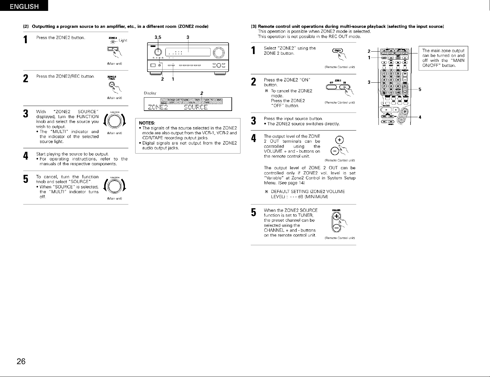
I2J Outputting a program source to an amplifier, etc., in a different room (ZONE2 mode)
Press the ZONE2 button zone= 3,5 3Light
[3] Remote control unit operations during multi-source playback )selecting the input source)
This operation is possible when ZONE2 mode is selected
This operation is not possible in the REC OUT mode
Press the ZONE2/REC button =_._=
With "ZONE2 SOURCE" ,........
knob and select the source you
displayed, turn the FUNCTION _O_,
wish to output
• The "MULTP' indicator and {Manunit}
the indicator of the selected
source light
4 Start playing the source to be output
• For operating instructions, refer to the
manuals of the respective components
To cancel, turn the function ,,,.,o.
• When "SOURCE" is selected,
knob and select "SOURCE" (O_,
the "MULTI" indicator turns
Otf {Man unit}
{Ma_n unit}
{Man unit}
2 1
DispFay 2
NOTES:
• The signals of the source selected in the ZONE2
mode are also output from the VCR-1. VCR-2 and
CDR/TAPE recording output iacks
• Digital signals are not output from the ZONE2
audio output jacks
ZONE 2 button
Select "ZONE2" using the %
{Remote Control unit)
Press the ZONE2 "ON" _.E=
TO cancel the ZONE2
button (_
mode
Press the ZONE2 {RemoteControlur/]t)
"OFF" button
Press the input source button
• The ZONE2 source switches directly
i_ The output level of the ZONE
2 OUT terminals can be k,L,/
controlled using the (_f_'_'_VOLUME + and - buttons on
the remote control unit
The output level of ZONE 2 OUT can be
controlled only if ZONE2 vol level is set
"Variable" at Zone2 Control in System Setup
Menu (See page 14)
DEFAULT SETTING (ZONE2 VOLUME
LEVEL) : _ - - dB (MINIMUM)
When the ZONE2 SOURCE _
5
function is set to TUNER, _-I_]
the preset channel can be
selected using the
CHANNEL + and - buttons
on the remote control unit
{Remote Control unit)
{Remote Control unk)
apt aN
0 0 0 0
can be turned on and
off with the "MAIN
The main zone output
ON/OFF" button
S
4
26
Page 27
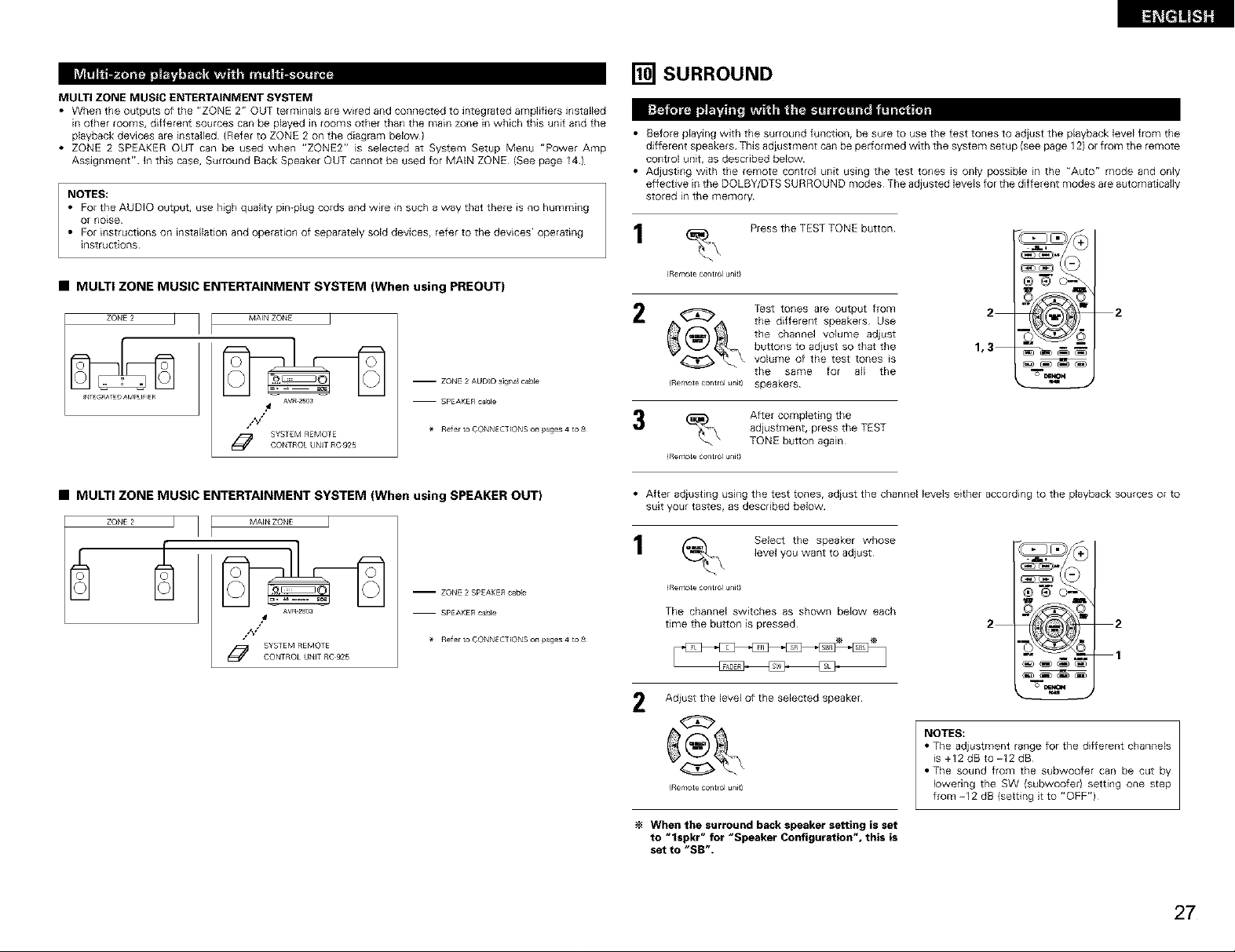
MULTI ZONE MUSIC ENTERTAINMENT SYSTEM
• When the outputs of the "ZONE 2" OUT terminals are wired and connected to integrated amplifiers installed
in other rooms, different sources can be played in rooms other than the main zone in which this unit and the
playback devices are installed (Refer to ZONE 2 on the diagram below)
• ZONE 2 SPEAKER OUT can be used when "ZONE2" is selected at System Setup Menu "Power Amp
Assignment" In this case, Surround Back Speaker OUT cannot be used for MAIN ZONE (See page 141
NOTES:
• For the AUDIO output, use high quality pin-plug cords and wire in such a way that there is no humming
Or no_se
• For instructions on installation and operation of separately sold devices, refer to the devices' operating
instructions
I_SURROUND
• Before playing with the surround function, be sure to use the test tones to adjust the playback level born the
different speakers This adiustment can be per[ormed with the system setup {see page 12) or from the remote
control unit, as described below
• Adjusting with the remote control unit using the test tones is only possible in the "Auto" mode and only
effective in the DOLBY/DTS SURROUND modes The adjusted levels for the different modes are automatically
stored in the memory
Press the TEST TONE button
• MULTI ZONE MUSIC ENTERTAINMENT SYSTEM (When using PREOUT)
ZONE 2 J
_T_G_ATED AM_U_IER
J j MA_N ZOt_E J
AVR.2803
.4
/,_/"
SYSTEM REMOTECONTROL UNIT RC 925
-- ZONE 2 AUDIO s]gaal cable
-- SPEAK£R cable
_eter to CONNECTIONS on pages 4 _o 8
• MULTI ZONE MUSIC ENTERTAINMENT SYSTEM (When using SPEAKER OUT)
J t MAI_ZONE J
-- ZONE 2 SPEAKE£ cabe
AVR_280a
/%/
O SYSTEM REMQTECONTROL UNIT _C 925
-- SPEAKER cable
$_ £eter to CONNECTIONS on pages 4 _o 8
_RemoLe ea_ltrol unit}
_ _ the different speakers Use
C_ the channel voJume adjust
Test tones are output from
buttons to adjust so that the
volume of the test tones _s
2
1,3
2
the same for all the
(Remote eo_ltrol unit) speakers
% After completing the
_RemoLe ea_ltrol unit}
adjustment, press the TEST
TONE button again
• After adiusting using the test tones, adiust the channel levels either according to the playback sources or to
suit your tastes, as described below
(_ Select the speaker whose
_Remote control unit}
level you want to adjust
The channel switches as shown below each
time the button is pressed
,AD=£ _A SL
Adiust the level of the selected speaker
2
2 2
1
IRemote control uni_)
When the surround back speaker setting is set
to "lspkr" for "Speaker Configuration", this is
set to "SB".
NOTES:
• The adjustment range for the different channels
is +12 dB to -12 dB
• The sound from the subwoofer can be cut by
lowering the SW {subwoofer) setting one step
from -I 2 dB {setting it to "OFF")
27
Page 28

• This function makes if possible to lower the volume of the front channels (FL, C and FR) or the rear channels
(SL, SR, SBL and SBR) together Use it for example to adiust the balance of the sound from the different
positions when playing mugi-channel music sources
.\ Select "FADER"
/Remotecontrou_it}
The channel switches in the order shown
below each time this button is pressed
_A0_R S,_ SL
2 Press the _1 button to reduce the volume of
the front channels, the _" button to reduce the
volume of the rear channels
_, _ The fader function does
_ not affect the SW channel
(Remote contro_ u_t}
The channel whose channel level is adiusted
lowest can be faded to -12 dB using the fader
function
If the channel levels are adiusted separately after
adjusting the fader, the fader adjustment values
are cleared, so adiust the fader again
1 3,5 1,4,6
Select the Dolby Surround Pro Logic 11mode
• The Dolby Pro Logic indicator lights
This is only displayed when setting the fader contro_
2 2
u
_4:_REAR
FL O,OdB
C O, OdB
FR O,Odi
SR O,Odi
SBR O. Od6
SBL O,OdB
SL O. 016
The Dolby Surround
Pro Logic ]] Cinema or
Music mode can be
chosen directly by
pressing the CINEMA
or MUSIC button on
the remote control
unit during playback in
the Dolby Surround
Pro Logic II mode
1
a
Play with the rll_ mark
• For operating instructions, refer to the manuals of the respective components
Set the surround parameter mode
The on-screen display differs according to whether the operation is
performed from the main unit or the remote control unit
Select the play mode
4
Display
source
program
_. J["iO[:,E C:ii'_E:m_.E_J
(Man un]Q _Remote co_ltrol unit}
(Man unit) _Remote co_trol unit)
Display
O0_ I I CINEMA EQ.I/
Th]_isthe sceen w_en operated with
theen_e con_olunk
_ I I OPTIONS4 I/
Th]_isthe soeen w_en operated with
theen_e con_olunk
..... r, ]q
Select the various parameters {See "Surround parameters _)" for a descriptioll of the various parameters)
5
DOLBY pL II MUSIC
p_
%
mur_Rcum _
IMan unk) _Remote control unit}
/ °,,.,,r,o,,
LC_ WIDTH
Set the various surround parameters
6
IMa_n unit) _Remote control unit)
When set with the on-screen display using
the remote control unit while in the MUSIC
mode, set the " E_" mark to "OPTION _"
using the • and • cursor buttons, then press
the 4 cursor button
Press the ENTER button to return to the
prewous screen
When the surround parameters are set using
7
the buttons on the main unit, stop operating
buttons after completing the settings The
settings are automatically finalized and the
normal display reappears after several seconds
When the settings are made using the buttons
on the remote control unit, press the
SURROUND PARAMETER button to finish
OPTIONAL pARAMETERS
pANORAMA _ < : kE_
DIMENSION < 3 k
CENTER WlOTH q 3
TONE 4
AFOM 4@_F
SB CH OUT
4 NRML(OFF)
Yes4
TONE 4
AFOM 4_b
SB CH OUT
<NRML(OFF)
Yes4
28
(Man unit} (Remote contro u_it}
Light D_sp[ay
_PRO LOGIC
_/ i \\
NOTES:
• There are four Dolby Sunound P_o Logic modes (NORMAL, PHANTOM, WIDE and 3 STEREO) The AVR-
2803 sets the mode automatically according to the types of speakers set during the system setup process
(page I0)
• Dolby Surround Pro Logic I] is a mode in which 2-channel sources are expanded into 51 channels
To output a surround back channel in this mode, set the "SB CH OUT" surround parameter to "NON
MTRX"
Page 29

Surround parameters
Pro Logic 11 Mode:
The Cinema mode is for use with stereo television shows and all programs encoded in Dolby Surround
The Music mode is recommended as the standard mode for autosound music systems (no video), and is
optional for AN systems¸
The Dolby PL mode offers the same robust surround processing as original Pro Logic in case the source
contents is not of optimum quality¸
Select one of the modes ("Cinema", "Music" or "Dolby PL")
Panorama Control:
This mode extends the front stereo image to include the surround speakers for an exciting "wraparound"
effect with side wall imaging
Select "OFF" or "ON"
Dimension Control:
This control gradually adjust the soundfield either towards the front or towards the rear¸
The control can be set in 7 steps from 0 to 6
Center Width Control:
This control adiust the center image so _t may be heard only from the center speaker; only from the left/right
speakers as a phantom image; or from all three front speakers to varying degrees¸
The control can be set in 8 steps from 0 to 7
Select the play mode
4
DTS NEO:6 Z
o
IMan unk) {Remote control uni9
Display
Select the various parameters (See "Surround parameters _" on page 33 for a description of the various
parameters)
P_
C G COMP4_
Thi_is the soeen wL_n op4_ratedwith
the en_e con_ol unk
%
CNTR IMAGE
40. 2)
LFE 4 0d@_
TONE 4
AFOM 4_1.
SB CH OUT
4NRML(ON) _*
IB]II[-1_I_[g_l _1'_1
• Surround playback can be performed for the analog input and PCM digital input 2-channel signals
The DTS NEO:6
Cinema or Music
o , .
no°
Select the DTS NEO:6 mode
1 3,51,4,6
1
0 (J C} (_)
mode can be chosen
directly by pressmg
the CINEMA or
MUSIC button on the
remote control unit
during playback in the
DTS NEO:6 mode
3
4,5,6
%
(Man unit} (Remote contro unit)
Play a program source
2
Set the surround parameter mode
3
(Man unit} (Remote contro u_it}
wm
OTSNEO:6 CINEMAEQ.
Thisisthescreenwhenoperatedwkh
fl_eremoteco_ltrolunit
LFE 4 OIBI*
TONE4
AFOM4_
[I Ct_Mp4_
SB CH OUT
4NR_L {ON) _*
Ye=4
IMan unk) IRemote control uni9
Set the various surround parameters
6
(Man unit) _Rer_ote co_)trol unit)
NOTE:
• When "Default" is selected and the _1cursor button is pressed, "MODE" and "TONE" are automatically
reset to the default values and "CINEMA EQ" is set to "OFF"
When the surround parameters are set using
7
the buttons on the main unit, stop operating
buttons after completing the settings The
settings are automatically finalized and the
normal display reappears after several seconds
When the settings are made using the buttons
on the remote control unit, press the
SURROUND PARAMETER button to finish
29
Page 30

1 3
4
D[sphy the surround parameter menu Dolby DIIlltal EB_IAXEQ* ] DTS ES OSC_6, 1E_ Eg,-
r_-_ _ O_C(_P_I[[_J_ D_C_I_I '
_ LFE _1 Od61' LFE 4 OdB_
IMainur_it) _Remotecontrolunit} _ YeS4 J _ Yes4
NOTE: The display on the screen differs depending on whether you are performing the operation from
the main unit or the remote control unit
_ TONE4
88 CH OUT SB _ OUT
4MTRXON _ 4MT_ ON _
m
1 3 2 4,5 2,6
Select the input source
[ Playback with digital input ]
_]} Select an input source set to digital
(COAXIAL!OPTICAL) (see page 13)
{Man unit} IRemu e control unit)
_2) Set the input mode to "AUTO" or "DTS"
{Man unit} IRen_ e control unit)
Select the Dolby/DTS Surround mode
2
%
(Remote contro unit)
3
Play a program source with the _[e_._, _ mark
m • The Dolby Digital indicator lights when
@,_ h_h_ playing Dolby Digital sources¸
• The DTS indicator lights when playing
Li_h_ DTS sources¸
_E_EC_
• The SIGNAL DETECT indicator lights
when playing 61-channel surround
sources containing the identification
signal
When the SIGNAL DETECT indicator is lit, we
recommend turning the surround back channel
using the SURROUND BACK button on the
remote control unit and main unit during playback
To use DTS 96/24 sources with the optimum
system, we recommend turning the surround
back channel off
When performing this operation from the main unit's
panel, press the SURROUND MODE button, then turn
the SELECT knob and select Dolby Pro logic II or DTS
NEO:6
(Main unit)
Operate the SURROUND BACK button to
switch Surround Back CH ON/OFE
w_ m_D
%
(Ma_a unit) (Remo_e control umt)
SORROm_
_CKOa
OUT_U _ Lights when the Surround Back
"_ £¢,t CH is on
5
Select the various parameters 6 Adiust the parameter settings
= "
IMan unk) _l_emote coatml unit}
• Dialogue Normalization
The dialogue normalization function is activated automatica,y when playing Doiby Digital program sources
Dialogue normalization is a basic function of Dolby Digital which automatically normalizes the dialog level
(standard level} of the signals which are recorded at different levels for different program sources, such as DVD,
DTV and other future formats that will use Dolby Digital¸
These contents can be verified with the STATUS button¸
i =',_."r',-_r ",' ,_ _r, i The number indicates the normalization level when the currently playing
ur i-"::_i::i .... ,_i,,::i_::_J program is normalized to the standard level¸
NOTE: When "Default" is selected and the • cursor button is pressed, "CINEMA EQ" and "D COMR" are
automatically turned off, "LFE" is reset, and the tone [s set to the default value
IMan ur_it) IRemote eo_ltrol unit)
3O
Page 31

Surround parameters
CINEMA EQ, (Cinema Equalizer):
Tile Cinema EQ function gently decreases the level of the extreme high frequencies, compensating for
ovedy-bbght sounding motion picture soundtracks Select this function if tile sound from the front speakers
is too bright
This function only works in the Dolby Pro Logic, Dolby Digital, DTS Surround, DTS NEO:6 and WIDE SCREEN
modes (The same contents are set for all operating modes)
D,COMR (Dynamic Range Compression):
Motion picture soundtracks have tremendous dynamtc range (the contrast between very soft and very loud
sounds) For listening late at night, or whenever the maximum sound level Js lower than usual, the Dynamic
Range Compression allows you to hear all of the sounds in the soundt_ack (but with reduced dynamic range)
(This only works when playing program sources recorded in Dolby Digital or DTS) Select one of the four
parameters {"OFF", "LOW", "MID" (middlel or "HI" {high)) Set to OFF for normal listening
LFE (Low Frequency Effect):
This sets the level of the LFE (Low Frequency Effect) sounds included in the source when playing program
sources recorded in Dolby Digital or DTS
If the sound produced from the subwoofer sounds distorted due to the LFE signals when playing Dolby Digital
or DTS sources when the peak limiter is turned off with the subwoofer peak limit level setting (system setup
menu), adjust the level as necessary
Program source and adiustmenf range:
I Dolby Digital: -10 dB to 0 dB
2 DTS Surround: -lg dB to 0 dB
When DTS encoded movie software is played, it is recommended that the LFE LEVEL be set to
0 dB for correct DTS playback,
When DTS encoded music software is played, it is recommended that the LFE LEVEL be set to
-10 dB for correct DTS playback,
TONE:
This adjusts the tone control (See "Surround parameters _" on page 33)
SB OH OUT:
(1) Dolby Digdal/DTS source
"OFF" ..................... Playback is conducted without using the surround back speaker
"NON MTRX" ......... Playback is conducted using the surround back speaker
The same signals those of the surround channels are output from the surround back
channels
"MTRX ON" ............ Playback is conducted using the surround back speaker
Surround back channel is reproduced using digital matrix processing
"NRML (OFF)" Playback is conducted without using the surround back speaker
"NRML (ON)" ......... Playback is conducted using the surround back speaker
(2) Other source
Surround back channel is reproduced using digital matrix processing
"OFF" ..................... Playback is conducted without using the surround back speaker
"ON" ....................... Playback is conducted using the surround back speaker
NOTE: This operation can be performed directly using the "SURROUND BACK" button on the main unit's
panel
[] DSP SURROUND SIMULATION
• The AVR-2803 is equipped with a high performance DSP (Digital Signal Processor) which uses digital signal
processing to synthetically recreate the sound field One of seven preset surround modes can be selected
according to the program source and the parameters can be adiusted according to the conditions in the
listening room to achieve a more realistic, powerful sound These surround modes can also be used for
program sources not recorded in Dolby Surround Pro Logic or Dolby Digital
1 ROCK ARENA Use this mode to achieve the feeling of a live collcett ill an arena with reflected sounds coming
2 JAZZ CLUB This mode creates the sound field of a live house with a low ceiling and hard walls This mode
MQNO MOVIE
3 {NOTE 1) Select this when watching monaural movies for a gloater sense of expansion
4 VIDEO GAME Use this to enioy video game sources
5 MATRIX consisti[ig of the difference component of the input signals (the component that provides the
6 VIRTUAL Select this mode to eiljoy a virtual sound fie_d, produced from the front 2<'hannel speakers
7 5CH/7CH STEREO phase) component of the [eft and right channels is output from the centel channel This mode
Depending on the program source being played, the effect may not be very noticeable
In this case, try other surround modes, without worrying about their names, to create a sound field suited
to your tastes
NOTE 1: When playing sources recorded in monaural, the sound will be one-sided if signals are only input to
one channel deft or right), so input signals to both channels If you have a source component with only
one audio output (monophonic camcorder, of c) obtain a "Y" adaptor cable to split the mono output
to two outputs, and connect to the L and R inputs
from all directions
glves iazz a very vivid realism
Select this to emphasize the sense of expansion for music sources recorded in stereo Signals
sense of expansion) processed for delay are output from the surround cha[_nel
In this mode, the signals of the front left channel are output from the left surround channel, the
slg[la_s of the front rlght chan[lel are Output from the dght surround channel, and the same (in
provides all speaker surrour_d soured, but without d_recdo[_a_ steering effeels, and works w_th any
stereo program source
Personal Memory Plus
This set is equipped with a personal memodze function that automatically memobzes the surround modes
and input modes selected for the input different sources When the input source is swdched, the modes set
for that source last time it was used are automatically recalled
The surround parameters, tone control settings and playback level balance for the different output
channels are memortzed for each surround mode
31
Page 32

• Operating the surround mode and surround parameters from the main unit's panel
• To operate the surround mode and surround parameters from the remote control unit
Sebct the surround mode for the input channel
(£emote control unit}
The surround mode switches in the following order
each time the DSP SIMULATION button is pressed:
2 I Display the surround parameter screen on the monitor IROCK ARENA _
(Remote contro unit} TONE 4
EFFECT410r
CH OUT
_*[_y eS<
3 Settheparameters 2
(£emote control unit}
mode
Turn the SELECT knob to select the surround [ 'Io_
I_, • : : :
I°°
{Main unit}
• When turned clockwise
V_RrUAL_ MA] £_X_ V_DEOGAM_ _ jAZZ CLUB _ ROCKARENA
• When turned counterclockwise
WRrUAL_ MA] £_X_ V_DEOGAM_ _ JAZZCLUB _ ROCKARENA
TO select the surround mode whib adiusting the surround parameters or tone control, press the
surround mode button then operate the selector
IMa_n unit)
I_ Press the SURROUND PARAMETER button
(Mainnit_ "Surround Modes and Parameters" on page 34
Display the parameter you want to adjust, then turn the SELECT knob to set it
Press and hold in the surround parameter button to select the parameter you want to
set
• The parameters which can be set differ for the different surround modes (Refer to
1 2 1,3
I TO end the setting mode, press the surround parameter button again
%
/Remote contro unit}
NOTES:
• When "Default" is selected and the < courser button is pressed, "CINEMA EQ" and "D COMR" are
automatically turned off, "ROOM SIZE" is set to "medium", "EFFECT LEVEL" to "10", "DELAY TIME" to
"30ms" and "LFE" to "0 dB"
• The "ROOM SIZE" expresses the expansion effect for the different surround modes in terms of the size
of the sound field, not the actual size of the listening room
32
NOTE:
• When playing PCM digital signals or analog signals in the DOLBY PRO LOGIC II, DTS NEO:6 modes and
the input signal switches to a digital signal encoded in Dolby Digital, the Dolby surround mode switches
automatically When the input signal switches to a DTS signal, the mode automatically switches to DTS
surround
Page 33

• Use the tone control setting to adjust the bass and treble as desired
• To operate the tone control from the remote control unit
• The tone control setting only affects the bent speakers
• if the tone control function is used, the main volume cannot be adiusted up to I8 dB (The maximum main
voJume leveJ differs in the different surround modes)
Display the surround parameter
screen on the monitoE
%
IRemote control umt)
Select "TONE"
2
_ Switch to the Tone Control Tone Cootrol /
(£emote controlunit}
The screen for the selected
surround mode appears¸
"TONE" cannot be selected
in the Direct mode¸
(£emote control unit}
Select Tone Defeat "OFF" ErTo.• O•fnt [_:_
To select Bass or Treble To settheIevel
ROCK ARENA
EFFECT410_
TONE4
ROCK ARENA
ROOM SIZE
4mRdium_
EFFECT410_
Bass I +8d$
Trabll 4 +4di
®
(Remote centre unit) (£emote co_ltrol unit}
(_ Enter the setting
(Remote contro unit)
The surround menu screen reappears
• To operate the tone control from the main unit
TONE CONTROL button is pressed_ ZO i_:::o _Q
The tone switches as follows each time the _=_1
(Main nit) 2 1
_,_ With the name of the volume to be adiusted selected, turn the SELECT knob to adjust
,,_0_. the level
(Mainnit) steps of 2 dB)
Surround parameters _3)
MODE: (DTS NEO:6)
• Cinema
This mode is optimum for playing movies Decoding is performed with emphasis on separation
performance to achieve the same atmosphere with 2-channel sources as with 6 1-channel sources
This mode is effective for playing sources recorded in conventional surround formats as well, because the
in-phase component is assigned mainly to the center channel (C) and the reversed phase component to
the surround (SL, SR and SB channels)
• Music
This mode is suited mainly for playing mumc The front channel (FL and FR) signals bypass the decoder
and are played dkectly so there is no loss of sound quality, and the effect of the surround signals output
from the center {C} and surround (SL, SR and SB) channels add a natural sense of expansion to the sound
field
ROOM SIZE:
This sets the size of the sound field
There are five settings: "small", "reed s" (medium-smafl}, "medium", "med I" (medium-large) and "large"
"small" recreates a small sound field, "large" a large sound field
EFFECT LEVEL:
This sets the strength of the surround effect
The level can be set in 15 steps from 1 to 15 Lower the level if the sound seems distorted
DELAY TIME:
In the matdx mode only, the delay time can be set within the range of 0 to 3OO ms
TONE CONTROL:
This can be set individually for the separate surround modes other than Direct
However, the same contents are set for DOLBY/DTS modes
BASS H TREBLE
• TOincrease the bass or treble:
Turn the control clockwise (The bass or treble sound can be increased to up to +10 dB in
• To decrease the bass or treble:
Turn the control clockwise (The bass or treble sound can be decreased up to -10 dB in
steps of 2 dB)
I_e]_,_]
I TO end the setting mode, press the surround parameter button again
%
(Remote contro unit)
33
Page 34

• Surround modes and parameters
Mode
D_RECT
STEREO
EXTE£NAL INPUT
DOLBY PRO LOGIC Jl
DTS NEO6
DOLBY DIGITAL
DTS SURROUND
(DTS ES MTRX 61}
5/7CN STEREO
ROCK ARENA
JAZZ CLUB
VIDEO GAME
MONO MOVIE
MATRIX
VIRTUAL
Front L/R CENTER SURROUND SUB SURROUND signals slgna_s signals
O x X © x O O O }
O x X © x O O O }
O _ @ © 'q X x }
c .; ', :o x }
O :# @ @ <_ Q × x x
O :# @ @ <_ O x x
O :# @ © 'q O O { -'}
O :# @ © 'q O O { -'}
O :# @ © 'q O O { -'}
O :# @ © 'q O O { -'}
O :# @ © 'q O O { -'}
O :# @ © 'q O O { -'}
0 x X @ x 0 0 { (}
(: Signal (: Able
(_!):X:Nosignal
Turned on or off by speaker configuration setting
Signals and adjustability _nthe different modes
Channel output playing When When When
When
play_ng p_aying playing
Dolby DTS PCM ANALOG
L/R WOOFER BACK L/R
the "SB CH OUT rr surround
parameter setting
Mode
DIRECT
STEREO
EXTERNAL INPUT
DOLEY PRO
LOGIC t[
DTS NEO6
DOLEY D_GITAL
DTS SURROUND
{DTS ES MT£X61)
5/7CH STE£EO
ROCK ARENA
JAZZ CLUB
VIDEO GAME
MONO MOVIE
MATRIX
VI£TUAL
Signals and adjustability _nthe different modes
Parameter (defauff values are shown ffl parentheses)
SURROUND PARAMETER
s s _
Z2"
x x × × × ×
C × x x x ×
(0dB)
X X × × × ×
0 ( (_OF) X X X
(0dB) r_'l_aEM/9{Note2)
C 0 0 _OF) x x X
(0dB) r_'l_aEM/9{Note3)
0 X (} _0 ) x x X
(0dB)
O X {} _O ) × × ×
(0dB)
O X × × × ×
(0dB)
C x x 0 0 X
(No el) {Medium) (10)
() X x 0 0 X
(OdB) {Medium) (10)
() X x 0 0 X
(OdB) {Medium) (10)
0 X x 0 0 X
(OdB) {Medium) (10)
O X x x x O
(0dB) 13@_sec}
x x x x
(0dB)
(Note 1) BASS: +8 dB, TREBLE: 4 dB
(Note 2) C_nema, DQLBY PL Mode only
(Note 3) C_nema Mode only
PRO LOGIC n NEO6 MUSIC
MUSICMODE ONLY MODE ONLY When payag
DoIbyDgital
2 _ g JDTS_g,_
_ _ _ _ _ CENTER IMAGE [3 CONIp LFE
× × × × C (
× × × × C (
× X × × X X
(} O O O x C C
{NRML{OFF)) _OFF) (3} (3} _OFF) (0dB)
(} × X X O (02) O O
(NRML(ON}) _OFF) (0dB)
(} × X X X O O
(MTRXON) _OFF) (0dB)
(} × X X X O O
(MTRXON) _OFF) (0dB)
X × X X X O O
X × X X X O O
X × X X X O O
X × X X X O O
X × X X X O O
X × X X X O O
X × X X X O O
O: Adjustable
>o Not adjustable
_OFF) (0dB)
_OFF) (0dB)
_OFF) (0dB)
_OFF) (0dB)
_OFF) (0dB)
_OFF) (0dB)
_OFF) (0dB)
34
Page 35

[] LISTENING TO THE RADIO
• Check that the remote control unit is set to AMP mode {TAPE, CDR/MD or CD)
Set the input function to "TUNER"
_Main unt) {Remote contro un_l
2 _.\ Watching the display, press
{Remotecontroun_
3
{Remote control un_
4
T_MMn/_L
{Remote control un_
if tuning does not stop at the desired station, use to
the "Manua] tuning" operation
the BAND button to select
the desired band (AM or
FM)
Press the MODE button to
set the auto tuning mode
"Auto" appears on the
display
Press the TUNING + (up) or -
(down) button
Automatic searching begins,
then stops when a station is
tuned in
1
3 2
1 4
103
Use the "Auto tuning" or "Manual tuning"
operation to tune in the station to be preset m
the memory
2 _ Press the MEMORY button
_Remote control unit}
_ Press the SHIFT button and
_Remote control unit}
4 aw_.\ Press the CHANNEL + {Up)
_Remote control unit}
_ Press the MEMORY button
_Remote control unit}
To preset other channels, repeat steps 2 to 5
A total of 40 broadcast stations can be preset
--- 8 stations (channels I to 8) in each of blocks
AtoE
select the desired memory
block (A to E)
or - (down} button to select
the desired preset channel (1
to 8)
again to store the station m
the preset memory
2,5
.m,. .m_,'_
3
4
o_
m
Set the input function to "TUNER"
IMain unt) {Remote contro unit}
2 _ Watching the display, press
IRe/note contro unit)
_ Press the MODE button to
{Remote contro unit}
the SAND button to select
the desired band (AM or
FM)
set the manual tuning mode
Check that the display's
"AUTO" indicator turns off
4
NOTES:
• When in the auto tuning mode on the FM band, the
• When the manual tuning mode is set, FM stereo
_m=r_a_ Press the TUNING + (up) or -
desired station¸
The frequency changes
(down) button to tune in the
{Remotecontrolunit) button is held _n
"STEREO" indicator lights on the display when a
stereo broadcast Js tuned in At open frequencies,
the noise is muted and the "TUNED" and
"STEREO" indicators turn off
broadcasts are received in monaural and the
"STEREO" indicator turns off
continuously when the
• The preset (broadcast) stations can be checked on the on screen display (OSD)
Press the ON SCREEN/DISPLAY button repeatedly until the "Tuner Preset
Stations" screen appears on the on screen display
_Remote control unit}
Tuner Pre=at Statl0ne
A1FI ST. 60_Hz
AZFI 89. IOMHz
A_FNgB, 10MHz
AIFII 0_l, 00MHI
ASFI 90. IONHz
ASFI g0. 10MHz
A?FN 90. IOMHI
ASFI 00. IOMHz
35
Page 36

• To call out preset stations from the remote control unit
WatcMng the display, press
the SHIFT button to select
the preset memory block
ooo_
1
2
the CHANNEL + (upl or -
2 _.\ Watching the display, press
(Remote centre unit}
• Calling out preset stations from the main unit's panel
_11 TIMING Press the TUNING PRESET
_Main un0 _ * *
(down) button to select the
desired preset channel
=©z
and select the desired _
2 _ Turn the FUNCTION knob
_Main unit)
RDS (works only on the FM band) is a broadcasting service which allows station to send additional information
along with the regular radio program signal
The following three types of RDS information can be received on this unit:
• Program Type (PTY)
PTY identifies the type of RDS program
The program types and their displays are as follows:
,_iii:_,._i:: I News [ {_i:{}8i< i'#_ ] RockMusic [FHOl"iii[ [_ ] Phonelrl
,_:_F:F:,_:U:i<:S I CurrentAffaifs [ _i[_:];Y i'#_ ] Mus,cEaSyListening['[RI:;I Jmi. ] Trave,
:[_'."=C i In,o,mo,,o.[L]:GHi H ] LightClassical eLm_[];i.ii_[E ] Leisure
..... ....... i s_o,,s [............=........... ] Serious [ ,.[[i;_:;_[;]_: ] Jazz Mus,o
station
Classical
Fi:,_,:i:_TF I _uoo,,o,,[OiHF.:RH ] o,,0,_u_,_[,:::,:::,UHii_:V]_o_,,_u_,o
• Traffic Program (TP)
TP identifies programs that carry traffic announcements
This allows you to easily find out the latest traffic conditions in your area before you leaving home
• Radio Text (RT}
RT allows the RDS station to send text messages that appear on the display
NOTE: The operations described below using the RDS, PTY and RT buttons will not function in areas in which
there are no RDS broadcasts
It,tB],,,']_I'_ m
Use this function to automatically tune to FM stations that provide RDS service
(_ Set the input function to
_Remote co_ltrol unit}
2 _. Press the RDS button until
_l_emotecontrolunit}
The main unit's display switches as follows
each time the RDS buttons are pressed
Display
=w=_ Press the CHANNEL + {up)
_l_emotecontrolunit}
If no RDS stations is found with above
operation, all the reception band are searched
When a broadcast station is found, that station's
name appears on the display
"TUNER"
"RDS SEARCH" appears on
the display
New tuning _y_tem for
your _onvenlen_el
1 Push
_RD5 s_tJon
[] -Traffic Inf_
[R0S] _/
[_] -Radio Text
Tune by preset [_[_]
Thisisfl_esc{een when operated
or - (downl button to
automatically begin the RDS
search operation
0000
1
3
2
°_
continue searching, repeat step 3
5
If no other RDS station is found when all the
frequencies are searched, "NO RDS" _s
displayed
New tuning _y_tem for
your _onv_nl_ncel
1 Push _ _
_RDS station
[] -Traffl_ Inf_
_ -Radio Text
2 Tune by preset _
This is the screen when operated
,:::i.ii._i.ii<'EI_o,,_e [,_::i:i,:,F_i'.i,:::_:] _,,oooe[':::i.i::':_E'.i; ] O,_,o__o_,_
s,::::z_i_i..ice: I Sc,ence [ 1.-......_,.L. ,_l-.,_"-_" ] Chi,dren's [ ,_={['i_K i'#` ] Folk fVlus,c
'.i:_i_::CEi::' I Varied [ _i;l]}C[[i;_h ] SocialAffalrs [iX[it IMi[H" [ ] D......... t8w
ptogrammes
,<:,F:,M I PopMus_c [,_:i[mh[[i]ii_(]i!'_ ] Relig]orl
36
Page 37

Use this function to find RDS stations broadcasting a designated program type (PTY)
For a description of each program type, refer to "Program Type (PTY)"
Set the input function to
(_\ "TUNER"
/Remote control u_it}
|;lli'a_fl
Use this function to find RDS stations broadcasting traffic program {TP stations)
_= Set the input function to
(_.\ "TUNER"
_Rensoteco_ltrolunit}
_ Press the RDS button until
(Remotecontrounit}
The main unit's display switches as follows
each time the RDS buttons are pressed
Display
_ to call out the desged
(£emote control u_t}
4
If there _s no station broadcasting the
designated program typewith above operation,
allthe reception bands are searched
"PTY SEARCH" appears on
the display
CROS]
New tunln= system for
your eonvenleneel
I Push [_]
_I_RDS station
Program category
[_] -Traffic Inf_ /
_] -Radio Text
2 Tune by preset [_][_
Thisisthescreenwhenoperated
Watching the display, press _ The station name is displayed on the display ir_ c._
the _ and _" cursor buttons w._ after searching stops
program type To continue searching, repeat step 4
[RDS-PTY]
I Salect ootelory
b 4_ button
AFFAIRS
E(_JCATE DRAk_ext _
INFO SPORT 1
2 Tune by preset [_][_
_B5 HIlO& 50MHI
This is the screen when operated
Press the CHANNEL + (up)
or - (down) button to
automatically begin the PTY
search operation
J
OOOO
1
4
3
3
2
Bt
If no other station broadcasting the designated _Remoteco_ltrolunit}
program type is found when all the frequencies
are searched, "NO PROGRAMME" _s
displayed
I Select category
by <_ button
NEWS AFFAIRS
INFO SFORT
EC_JCATE DRAk_ext_
2 Tuna by preset [_[_
_485P_10&50MHz
This is the screen when operated
4
5
_ Press the RDS button until
_Remotecontrolunit}
The main unit's display switches as follows
each time the RDS buttons are pressed
Display
New tun[hi system for
1 Push [_
n_m-Traffle Int_
2 Tuna by praset [_[_]
_B5 _10& 50MHI
This is the screen when operated
EL
If no TP station is found with above operation,
allthe reception bands are searched
The station name _s displayed on the display
aftersearching stops
To continue searching, repeat step 3
If no other TP station is found when all the
frequencies are searched, "NQ PROGRAMME"
is displayed
New tunln_ system for
1 Push _
2 Tune by preset [_[_]
• 85 _10& 50MHz
This is the screen when operated
"TP SEARCH" appears on
the display
your convanienee!
[_D-RDS atatlon
[_[_-Program ¢8tegory
[ROS) /
[_ -RADIO Text
Press the CHANNEL + (up)
or - (down) button TP search
begins
[ R O S ] ]
your convenieneel
[_-RDS station
[_l_-Progrem category
[_] -Traffic Inf_
[_] -RAdio Text
OOOO
1
3
2
I
37
Page 38

"RT" appears on the display when radio text data is
received
When the RDS button is pressed until "RT" appears
on the display while receiving an RDS broadcast
station, the text data broadcast from the station is
displayed To turn the display off, use the _1 and I_
cursor buttons on the remote control unit If no text
data is being broadcast, "NO TEXT DATA" _s
displayed
New tunin| system for
your ¢onveniencei
I Push [!_
[_]-RDS station
[_-Pr 0gr am catsi0ry
[_]-Traffic Inf=_
CROS] J
_Rmdlo Text <[_]_
¢tB6 RI1O5,50MI_
This _s the screen when operated
"<1" -- ! "lib "
"RDS"
[] LAST FUNCTION MEMORY
• This unit is equipped with a last function memory which stores the input and output setting conditions as they
were immediately before the power is switched off
This function eliminates the need to perform complicated resettings when the power is switched on
• The unit is also equipped with a back-up memory¸ This function provides approximately one week of memory
storage when the main unit's power switch is oft and with the power cord disconnected¸
[] INITIALIZATION OF THE MICROPROCESSOR
When the indication of the display is not normal or when the operation of the unit does not shows the reasonable
result, the initialization of the microprocessor _s required by the following procedure
I operationSwitch off the unit using the main unit's powerswitch [TOo_ i_ JI .J : : : _ O
Hold the following FRONT SPEAKER button
and ZONE 2 button, and turn the main unit's _=O_
power operation switch on
Check that the entire display is flashing with an
interval of about I second, and release your
fingers from the 2 buttons and the
m_croprocessor will be initialized
NOTES:
• If step 3 does not work, star[ over from step I
• If the microprocessor has been reset, all the button settings are reset to the default values (the values set
upon shipment from the factory)
Turning on the main unit's power from the standby mode without using the remote control unit
• Press the power switch on the main unit while pressing the SOURCE button on the main unit's panel to
turn on the power¸
1,2 2
[] TROUBLESHOOTING
g a problem should arise,first check the following.
1. Are the connections correct ?
2. Have you operated the receiver according to the Operating Instructions ?
3. Are the speakers, turntable and other components operating property ?
If this unit is not operating properly, check the items listed in the table below Should the problem persist, there
may be a malfunction
Disconnect the power immediately and contact your store of purchase
Symptom
DISPLAY not lit and sound not
ploduced when power switch set
to on
DISPLAY _it but sound not
produced
D_SPLAY not _it and power
indicatotisflashJngrapid_y
8
s
c
Sound produced only from one
channe_
Posit_ons ofinstruments
reversed during stereo
playback¸
The on screen d_splay is not
d_splayed
System setup screen does not
appear
Humming noise produced when
record _s p_aying
Howling noise produced when
volume is high
Soundis distorted
Volume isweak
Cause
• Powel cord not p_ugged in
securely
• Speaker cords not securely connected
• Improper position of the audio
function button¸
• Volume control set to m_nlmum
• MUTING is on
• Digital s_gnals not input Digital input
selected
• Speaker terminals are short
circuited
• B_ock the ventilation holes of the
set
• The unit _s opelating at continuous
Ngh power conditions and/or
inadequate ventilation
• Incomplete connection of speaker
cords
• incomplete connection of
input/outputcolds
• Revers e corlnect_ons of Jeft and
right speakers or left and dght
input/outputcolds
• "On screen disp]ay"Js set to off on
the system setupmenu screen¸
• You are using headphones
• Mute mode is set
• Monitor _/ not connected to AVR
2803
• Ground wire of turntaMe not
connected properly
• IncompJete PHONO jack
connection
• TV ot radio ttansmlssion antenna
nearby
• Turntable and speaker systems too
close together
• Floor is unstaMe and vibrates easily
• Stylus pressure too weak
• Dust ol dirt on stylus
• Cartlidge defective¸
• MC caltlidge being used
• Check the insertion of the power
cord plug
• Turn the power on With the remote
• Connec I secuiely
• Set to a suitabFe position
• Turn volume up to suitable level 23
• Switch off MUTING 25
• Input digital s_gna_s or select input 23
iacks to which digital signals are
being input
• Switch power off, connect speakers 8
properly, then sw_tch power back
on
• Turn off the set's power, then 3, 7
ventilate it well to cool it down
• Turn off the set's power, then 3, 7
ventilate it well to cool it down
• Connect securely
• Connect securely
• Check lett and right connections
• Set "on screen display" on the /5
system setup menu screen to on
• Unplug the headphones from the 25
headphones iack
• Cancel the mute mode 25
• Connect a monitor TV 5, 6
• Connect securely 4
• Corlnect securely 4
• Contact your store of purchase
• Separate as much as possible
• Usa cushions to absorb speaker
v_brations transmitted by floor _f
turntable is not equipped with
_Rsulators, use audio _nsulatots
{commorfly available)
• Apply proper stylus pressure
• Check stylus
• Replace cartridge
• Replace with MM cartndge or use a 4
head amp_ifie r or step up
transformer
Measures
control unit after tulning the
POWER sw_tch on
Once the set is cooled down, turn
the power back on
Once the set is cooled down, turn
the power back on
Page
4
22
8
4--8
8
38
Page 39

Symptom Cause Measures Page
• Battenes dead • Replace with new batteries 17
• Remotecontrolunittoofarfromthis • Movecloser 17
Ur_lt
• Obstacle between this unit and • Remove obstacle 17
unit is used
E • _) and O ends of battery inserted i[+ • Insert batteries propedy 17
remote control unit
• Different button is being pressed • Press the proper button
reverse
A 6 1+channel system is a conventional 5 1-channel System to which the "surround back" (SB) channel has been
added This makes it easy to achieve sound poskioned directly behind the listener, something that was
previously difficult with sources designed for conventional multi surround speakers In addition, the acoustic
image extending between the sides and the rear _s narrowed, thus greatly improving the expression of the
surround signals for sounds moving from the sides to the back and from the front to the point directly behind the
listening position
Change of positioning and acoustic in.age
with 5 _hannel systems
Change of positioning and acoustic image
with 6.1=6hannel systems
[] ADDITIONAL INFORMATION
There are currently various types of multi-channel signals {signals or formats with more than two channels)
• Types of multi-channel signals
Dolby Digital, Dolby Pro Logic, DTS, high definition 3-1 signals (Japan MUSE Hi-Vision audio), DVD-Audio,
SACD (Super Audio CD), MPEG multi-channel audio, etc
"Source" here does not refer to the type of signal (format) but the recorded content Sources can be divided
into two maior categories
Types of sources
• Movie audio Signals created to be played in movie theaters In general sound is recorded to be played in
IIKOvie theater sound field
D[]EE] []
DI ID
[ sB )
Multiple sur_nd s_ak_s
IFor6 I channel system_
• Other types of audio These signals are designed to recreate a 360 ° sound field using three to five
movie theaters equipped with multiple surround speakers, regardless of the format (Dolby
Digital, DTS, etc)
LiStening room _und field
In this case if is important to achieve the same
sense of expansion as in a movie theater with
the sunound channels
To do so, in some cases the number of
surround speakers is increased (to four or
eight) or speakers with bipolar or dipolar
properties are used
\ SB: Surround back channel
speakers¸
i i i i
i SLI ISR i
i i i i
i+++i
i i i i
,[_, 0 , ,
i i i i
i i i i
I J
I_ _JlI_ SB "_I, _I
[3 N /_
[]_
[_ i_1
E_ E_ E_ E_ E_ E_
SB ch /
Movement of acoustic image from SB to SL
With this set, speaker(s) for 1or 2 channels are required to achieve a 6 1-channel system (DTS+ES, etc) Adding
these speakers, however, increases the surround effect not only with sources recorded in 61 channels but also
with conventional 2- to 5 t-channel sources The WIDE SCREEN mode is a mode for achieving surround sound
with up to 71 channels using surround back speakers, for sources recorded in conventional Dolby Surround as
well as Dolby Digital 5 1-channel and DTS Surround 5 1-channel sources Furthermore, all the Denon original
surround modes {see page 31) are compatible with 7 1+channel playback, so you can enjoy 7 1-channel sound
with any signal source
• Number of surround back speakers
Though the surround back channel only consists of 1 channel of playback signals for 6 1+channel sources
{DTS-ES, etc), we recommend using two speakers¸ When using speakers with dipolar characteristics in
particular, it is essential to use two speakers¸
Using two speakers results in a smoother blend with the sound of the surround channels and better sound
positioning of the surround back channel when listening from a position other than the center¸
• Placement of the surround left and right channels when using surround back speakers
Using surround back speakers greatly improves the positioning of the sound at the rear¸ Because of this, the
surround left and right channels play an important role in achieving a smooth transition of the acoustic image
from the front to the back¸ As shown on the diagram above, in a movie theater the surround signals are also
produced from diagonally in front of the listeners, creating an acoustic image as if the sound were floating _n
space¸
To achieve these effects, we recommend placing the speakers for the sur_und left and right channels slightly
more towards the front than with conventional surround systems¸ Doing so sometimes increases the
surround effect when playing Conventional 51-channel sources in the 61 surround or DTS-ES Matrix 61
mode¸ Check the surround effects of the various modes before selecting the surround mode¸
Movement of acoustiC image from SR to SB to SL
In this case the speakers should surround the listener from all sides to
create a uniform sound field from 360°¸ Ideally the surround speakers
should function as "point" sound sources in the same way as the front
speakers¸
SL SR
These two types of sources thus have different properties, and different speaker settings, particularly for the
surround speakers, are required in order to achieve the ideal sound
39
Page 40

2. When not using surround back speakers
Here we descdbe a number of speaker settings for different purposes Use these examples as guides to set up
your system according to the type of speakers used and the main usage purpose
I, DTS-ES compatible system (using surround back speakers)
(I} Basic setting for primarily watching movies
This is recommended when mainly playing movies and using regular single way or 2-way speakers for
the surround speakers
• Set the front speakers with their front
surfaces as flush with the TV or monitor
screen as possible Set the center
speaker between the front left and right
speakers and no further from the listening
¢
position than tile front speakers
• Consult the owner's manual for your
subwoofer for advice oil placing the Asseenfromtheside
subwoofer within the listening room
• If the surround speakers are direct-radiating {monopolar) then place them
slightly behind and at an angle to the listening position and parallel to the
walls at a position 60 to 90 centimeters above ear level at the prime listening
Su round _ao_, speakers
{1 sekr or 2 spkrs}
As seen from above
position
• When using two surround back speakers, place them at the back facing the
front at a narrower distance than the front left and right speakers When
using one surround back speaker, place it at tile rear center facing the front
at a slightly higher position {0 to 20 cm) than the surround speakers
• We recommend installing the surround back speaker(s) at a slightly
downward facing angle This effectively prevents the surround back
channel signals from reflecting off the monitor or screen at the front center,
resulting in interference and making the sense of movement from the front
to the back less sharp
(2} Setting for primarily watching movies using diffusion type speakers for the surround speakers
For the greatest sense of surround sound envelopment, diffuse radiation speakers such as bipolar
types, or dipolar types, provide a wider dispersion than is possible to obtain from a direct _adiating
speaker (monopolar) Place these speakers at either side of the prime listening position, mounted above
ear level
Path of the surround sound from the
speakers to the listening position
• Set the front speakers, center speaker
and subwoofer in the same positions as
In example (1) _oi, s_i_lt_
• It is best to place the surround speakers
directly at the side or slightly to the front
of the viewing position, and 60 to 90 cm
above the ears
• Same as surround back speaker Asseenfromtheside
installation method (1)
Using dipolar speakers for the surround back speakers as well _s more
Surround back speakers
_1 spkr or 2 spkrs)
As seen_omabove
effective
• Connect the surround speakers to the surlound speaker iacks
• The signals from the surround channels reflect off the walls as shown on the
diagram at the left, creating an enveloping and realistic surround sound
presentation
For multi-channel music sources however, the use of bipolar or dipolar
speakers mounted at the sides of the listening position may not be
satisfactory in order to create a coherent 360 degree surround sound field
Connect another pair of direct radiating speakers as described in example {3)
and place them at the rear corners of the room facing towards the pnme
listening position
• Set the front speakers with their front sur[aces
as flush with the TV or monitor screen as Suroundspeaker
possible Set the center speaker between the
front left and right speakers and no further from
the listening position than the front speakers
• Consult the owner's manual for your
subwoofer for advice on placing the subwoofer
within the listening room
• If the surround speakers are direct-radiating Asseen_omthesMe
(monopolar) then place them slightly behind
and at an angle to the listening position and parallel to the wails at a position
60 to 90 centimeters above ear level at the prime listening position
_urro_ndspe_ers/
As seen from above
The AVR-2803 is equipped with a digital signal processing circuit that lets you play program sources in the
surround mode to achieve the same sense of presence as in a movie theater
Dolby Surround
(1) Dolby Digital
Dolby Digital isthe multi-channel digital signal format developed by Dolby Laboratories
Dolby Digital consists of up to "51" channels - front left, front right, center, surround left, surround right,
and an additional channel exclusively reserved for additional deep bass sound effects (the Low Frequency
Effects - LFE - channel, also called the "1" channel, containing bass frequencies of up to 120 Hz)
Unlike the analog Dolby Pro Logic format, Dolby Digital's main channels can all contain full range sound
information, from the lowest bass, up to the highest frequencies - 22 kHz The signals within each channel
are distinct from the others, allowing pinpoint sound imaging, and Dolby Digital offers tremendous dynamic
_ange from tile most powerful sound effects to tile quietest, softest sounds, free from noise and distortion
• Dolby Digital and Dolby Pro Logic
Comparison ot home surround
systems
No recordedch_nr_e[s(e_ements)
No playbackcharlrle_s
Playbackchariness(max)
Audio processing
High frequency p_aybacklimit of
surround channe_
D_gita_d_sclete processing Dolby Digital Analog m_tlix plocess_ng Dolby
encoding/decodln_ Surround
Dolb_/Digital Dolb_/Pro Logic
51 ch 2 ch
51 ch 4 ch
L R, C, SL, SR, SW L R, C, S (SW lecommended)
20 kHz 7 kHz
4O
Page 41

• Dolby Digital compatible media and playback methods
Marks indicating Dolby Digital compatibility: rlq_]
The following are general examples Also refer to the player's operating Jnstruc6ons
Media Do,by Digital output iacks P_avback method kefet ence page)
LD (VDPI Coaxial Dolb_/Digital RF output jack Set the input mode to "AUTO'
DVD Optica_ ot coax_a_digital output Set the input mode to "AUTO'
{satellite broadcasts, CATV etc I (same as for PCM) {Page 23}
Others Optica_ or coax_a_digital Output Set the input mode to "AUTO'
1 Please use a commercially available adapter when connecting the Dolby Digkal RF output jack of the
LD player to the digital input jack
Please refer to the instruction manual of the adapter when making connection
2 Some DVD digital outputs have the function of switching the Dolby Digital signal output method
between "bit stream" and "(convert to) PCM" When playing in Dolby Digital surround on the AVR-
2803, switch the DVD player's output mode to "bit stream" In some cases players are equipped with
both "bit stream + PCM" and "PCM only" digital outputs In this case connect the "bit stream +
PCM" iacks to the AVR-2863
DImlTAL
/ IPage 23}
{same as for PCM) _ 2 (Page 23}
Digital Theater Surround (also called simply DTS) is a multi-channel digital signal format developed by Digital
Theater Systems
DTS offers the same "51 " playback channels as Dolby Digital (front left, front right and center, surround left and
surround right) as well as the stereo 2-channel mode The signals for the different channels are fully independent,
eliminating the risk of deterioration of sound quality due to inter[erence between signals, crossfalk, etc
DTS features a relatively higher bit rate as compared to Dolby Digital (1234 kbps for CDs and LDs, 1536 kbps for
DVDs) so it operates with a relatively low compression rate Because of this the amount of data is great, and
when DTS playback is used in movie theaters, a separate CD-ROM synchronized with the film is played
With LDs and DVDs, there is of course no need for an extra disc; the pictures and sound can be recorded
simultaneously on the same disc, so the discs can be handled in the same way as discs with other formats
There are also music CDs recorded in DTS These CDs include 5 1-channel surround signals (compared to two
channels on current CDs) They do not include picture data, but they offer surround playback on CD players that
are equipped with digital outputs (PCM type digital output required)
DTS surround track playback offers the same intricate, grand sound as in a movie theater, right in your own
listening room
• DTS compatible media and playback methods
Marks indicating DTS compatibility: _ and _1_
The following are general examples Also refer to the player's operating instructions
Media Dolby Digitaloutput iacks Playbackmethod {reference page)
(2} Dolby Pro Logic ]1
• Do]by Pro Logic l] _s a new multi-channel playback format developed by Dolby Laboratories using
feedback logic steering technology and offering improvements over conventional Dolby Pro Logic circuits
• Do]by Pro Logic [1 can be used to decode not only sources recorded in Dolby Surround (_) but also
regular stereo sources into five channels (front left, front right, center, surround left and surround right) to
achieve surround sound
• Whereas with conventional Dolby Pro Logic the surround channel playback frequency band was limited,
Dolby Pro Logic ]] offers a wider band lunge (20 Hz to 20 kHz or greater) hi addition, the surround
channels were monaural (the surround left and right channels were the same) with previous Dolby Pro
Logic, but Dolby Pro Logic ]I they are played as stereo signals
• Various parameters can be set according to the type of source and the contents, so it is possible to
achieve optimum decoding (see page 28)
Sources recorded in Dolby Surround
These are sources in which three or more channels of surround have been recorded as two channels of
signals using Dolby Surround encoding technology
Dolby Surround is used for the sound tracks of movies recorded on DVDs, LDs and Video cassettes to
be played on stereo VCRs, as well as for the stereo broadcast signals of FM radio, TV,satellite broadcasts
and cable TV
Decoding these signals with Dolby Pro Logic l] makes it possible to achieve muk[-channel surround
playback The signals can also be played on ordinary stereo equipment, in which case they provide
normal stereo sound
There are two types of DVD Dolby surround recording signals
_ 2-channel PCM stereo signals
_2) 2-channel Dolby Digital signals
When either of these signals is input to the AVR-2803, the surround mode is automatically set to Dolby
Pro Logic _] when the "DOLBY/DTS SURROUND" mode is selected
• Sources recorded in Dolby Surround are indicated with the logo mark shown below,
Dolby Surround support mark: Illrl_
Manufactured under license from Dolby Laboratories
"Dolby", "Pro Logic" and the double-D symbol are trademarks of Dolby Laboratories
CD OpticaJor coa×Jaldigitaloutput Set the input mode to "AUTO" or "DTS' {page2:1)Never set
LD {VDPI {sameas for PCM) _ 2 the mode to "ANALOG" ot "PCM" _ /
DVD OpticaJor coaxlal digltal output
1 DTS signals are recorded in the same way on CDs and LDs as PCM signals Because of this, the un-
decoded DTS signals are output as random "hissy" noise from the CD or LD player's analog outputs If
this noise _s played with the amplifier set at a very high volume, it may possibly cause damage to the
speakers To avoid this, be sure to switch the input mode to "AUTO" or "DTS" before playing CDs or LDs
recorded in DTS Also, never switch the input mode to "ANALOG" or "PCM" during playback The same
holds true when playing CDs or LDs on a DVD player or LD/DVD compatible player For DVDs, the DTS
signals are recorded in a special way so this problem does not occur
_2
The signals provided at the digital outputs of a CD or LD player may undergo some sort of internal signal
processing (output level adjustment, sampling frequency conversion, etc) hi this case the DTS-encoded
signals may be processed erroneously, in which case they cannot be decoded by the AVR-2903, or may
only produce noise Before playing DTS signals for the first time, turn down the master volume to a low
level, star[ playing the DTS disc, then check whether the DTS indicator on the AVR-2863 (see page 36)
lights before turning up the master volume
_3
A DVD player with DTS-compafible digital output is required to play DTS DVDs A DTS Digital Output logo
is featured on the front panel of compatible DVD players Recent DENON DVD player models feature DTS-
compatible digital output - consult the player's owner's manual for information on configuring the digital
output for DTS playback of DTS-encoded DVDs
Manufactured under license from Digital Theater Systems, Inc US Pat No 5,451,942, 5,956,674, 5,974,380, |
5,978,762 and other world-wide patents issued and pending
"DTS","DTS-ES Extended Surround" and "Neo:6" are trademarks of Digital Theater Systems, Inc @I996,
2000 Digital Theater Systems, Inc All Rights Reserved
{same as for PCM) _ 2 the mode to "ANALOG" ot "PCM" _ /
OpticaJor coaxial digital output Set the input mode to "AUTO" or "DTS' {page2:1)Never set
{same as for PCM) _ 3 Set the input mode to "AUTO" ot "DTS' {page23)
q
]
41
Page 42

DTS-ES Extended Surround is a new multi-channel digital signal format developed by Digital Theater Systems
Inc While offering high compatibility with the conventional DTS Digital Surround format, DTS-ES Extended
Surround gready improves the 3BO-degree surround impression and space expression thanks to fur[her expanded
surround signals This format has been used professionally in movie theaters since 1999
In addition to the 51 surround channels (FL, FR, C, SL, SR and LFE), DTS-ES Extended Surround also offers the
SB (Sunound Back, sometimes also referred to as "surround center") channel for sunound playback with a total
of 61 channeJs DTS-ES Extended Surround includes two signal formats with different surround signal recording
methods, as described below
• DTS-ES TM Discrete 6.1
DTS-ESTM Discrete 61 is the newest recording format With it, all 61 channeJs (including the SB channel)
are recorded independently using a digital discrete system The main feature of this format is that because
the SL, SR and SB channels are fully independent, the sound can be designed with total freedom and it is
possible to achieve a sense that the acoustic images are moving about freely among the background sounds
surrounding the listener from 360 degrees
Though maximum per[ormance is achieved when sound tracks recorded with this system are played using
a DTS-ES decode_, when played with a conventional DTS decoder the SB channel signals are automatically
down-mixed to the SL and SR channels, so none of the signal components are lost
• DTS-ES TM Matrix 6.1
With this format, the additional SB channel signals undergo matrix encoding and are input to the SL and SR
channels beforehand Upon playback they are decoded to the SL, SR and SB channels The performance
of the encoder used at the time of recording can be fully matched using a high precision digital matrix
decoder developed by DTS, thereby achieving surround sound more faithful to the producer's sound design
aims than with conventional 51- or 6 1-channel systems
In addition, the bit stream format is 100% compatible with conventional DTS signals, so the effect of the
Matrix 6I format can be achieved even with 5 t-channel signal sources Of course it is also possible to play
DTSES Matrix 61 encoded sources with a DTS 5 1-channel decoder
When DTS-ES Discrete 61 or Matrix 6I encoded sources are decoded with a DTS-ES decoder, the format
is automatically detected upon decoding and the optimum playing mode is selected However, some Matrix
61 sources may be detected as having a 5 t-channel format, so the DTSES Matrix 61 mode must be set
manually to play these sources
(For instructions on selecting the surround mode, see page 301
The DTS-ES decoder includes another function, the DTS Neo:6 surround mode for 6 1-channel playback of
digital PCM and analog signal sources
• DTS Neo:6 TMsurround
This mode applies conventional 2-channel signals to the high precision digital matrix decoder used for DTS-
ES Matrix 61 to achieve 6 1-cbannel surround playback¸ High precision input signal detection and matrix
processing enable full band reproduction (frequency response of 20 Hz to 20 kHz or greater) for all 6I
channels, and separation between the different channels is _mproved to the same level as that of a digital
discrete system¸
DTS Neo:6 surround includes two modes for selecting the optimum decoding for the signal source¸
• DTS Neo:6 Cinema
This mode is optimum for playing movies Decoding is per[ormed with emphasis on separation
performance to achieve the same atmosphere with g-channel sources as with 6 1-channel sources
This mode is effective for playing sources recorded in conventional surround formats as well, because the
in-phase component is assigned mainly to the center channel (C) and the reversed phase component to
the surround (SL, SR and SB channels)
• DTS Nee:6 Music
This mode is suited mainly for playing music Changes in the sound qualify are reduced by decoding with
emphasis on the front channel signals {FL and FRI, and a natural sense of expansion _sg_ven to the sound
field by the effect of the surround signals output from the center (C) and surround (SL, SR and SB)
channels
IB21tr..*'l_k:_l
The sampling frequency, number of bits and number of channels used for recording of music, etc, in studios has
been increasing in recent years, and there are a growing number of high quality signal sources, including 96
kHd24 bit 5 1-channel sources
For example, there are high picture/sound quality DVD video sources with 96 kHz/24 bit stereo PCM audio tracks
However, because the data rate for these audio tracks is extremely high, there are limits to recording them on
two channels only, and since the quality of the pictures must be restricted it is common to only include still
pictures
In addition, 96 kHz/24 bit 5 1-channel surround is possible with DVD audio sources, but DVD audio players are
required to play them with this high quality
DTS 96/24 is a multi-channel digital signal format developed by Digital Theater Systems Inc in order to deal with
this situation
Conventional surround formats used sampling frequencies of 48 or 44 1 kHz, so 20 kHz was about the maximum
playback signal frequency With DTS 96/24, the sampling frequency is increased to 96 or 882 kHz to achieve a
wide frequency _ange of over 40 kHz
In addition, DTS 96/24 has a resolution of 24 bits, resulting in the same frequency band and dynamic lange as 96
kHd24 bit PCM
As with conventional DTS Surround, DTS 96/24 is compatible with a maximum of 51 channels, so sources
recorded using DTS 96/24 can be played in high sampling frequency, multiple channel audio with such normal
media as DVD videos and CDs
Thus, with DTS 96/24, the same 96 kHz/24 bit muki-channel surround sound as with DVD-Audio can be achieved
while viewing DVD-Video images on a conventional DVD-Video player {_11 Furthermore, with DTS 96/24
compatible CDs, 882 kHz/24 bit multi-channel surround can be achieved using normal CD/LD players ( _ 1)
Even with the high quality multFchannel signals, the recording time is the same as with conventional DTS
surround sources
What's more, DTS 96/24 is fully compatible with the conventional DTS surround format, so DTS 96/24 signal
sources can be played with a sampling frequency of 48 kHz or 441 kHz on conventional DTS or DTS-ES surround
decoders (÷ 2)
1: A DVD player with DTS digital output capabilities (for CD/LD players, a player with digital outputs for
conventional DTS CDs/LDs) and a disc recorded in DTS 96/24 are required
2: The resolution is 24 or 20 bits, depending on the decoder
42
Page 43

Detault setdngs
80 Hz
LFE
S_lround L & R
30m(10 ft}
Mode
DrRECT
STEREO
EXTERNAL INPUT
DOLBY PRO LOGrC II
DTS NE06
DOLSY DIGITAL
DTS SURROUND
{DTS ES MT£X61)
5/ICH STE£EO
ROCK ARENA
JAZZ CLUB
VIDEO GAME
MONO MOVIE
MATRIX
VI£TUAL
Signals and adjustability irl the different modes
Charlnel output play_ng When When When
Frorlt tdR CENTER [JR WOOFER BACK [dR Sigrlals
SURROUND SUB SURROUND Digital slgrla_s sigrlals signals
When
p_aying playing playirlg
Dolby DTS PCM ANALOG
C x X ._ x C C {} O
C X x ._ X C C {} O
C i <_ ._ :i_ X x X O
c _ '¢ .; x _> O
{} i <_ .; _i_ X {} x x
{} i <_ .; _i_ C {} {} 0
{} i <_ .; _i_ C {} {} 0
{} i <_ .; _i_ C {} {} 0
{} i <_ .; _i_ C {} {} 0
{} i <_ .; _i_ C {} {} 0
{} i <_ .; _i_ C {} {} 0
{} X x .; X C {} {} 0
OFF
Surround Back
Vat_able
Subwoofer _ +15 dB
Auto Surround MOde _ON
On Screen Display _ ON
Setup Lock _ OFF
_: Signal
{6)i No slg_a_
Turned or+ or off by speaker configuration setting
the "SB CH OUT" surround
parameter setting
43
Page 44

Mode
D_RECT
STEREO
EXTERNAL INPUT
DOLBY PRO
LOGIC I]
DT5 NED6
DOLBY DIGITAL
DTS SURROUND
(DT5 ES MTRX 6 1}
5/7CN STEREO
ROCK ARENA
JAZZ CLUB
VIDEO GAM£
MONO MOVI£
MATRIX
VIRTUAL
Signals and adjustability in the different modes
Parameter (default values are shown in parentheses}
SURROUND PARAMETER
s y
zz ±> _
x x x x x
0 x
_Od£}
X X X X X
O {} O lO_Fi
_Od£} !CINEMN INote2)
O {} O lO_Fi
_Od[_} (CINEMP_ (Note3)
O x {} IO_Fi
_Od£}
O x {} IO_Fi
_Od£}
0 X
_Od£}
(7 X O (
{Note1) IMed um) _101
(7 X O (
_Od£} IMed urn) _101
(7 X O (
_Od£} IMed urn) _101
(7 X O (
_Od£} IMed urn) _101
(7 X (.
_0dB} (30msec}
0 X
_Od£}
(Note 1 ) BASSr +8 dB TREBLE: 4 dB
(Note 2) Cinema, DOLBY PL Mode only
(Note 3) Cinema Mode only
Jux
mu_
PRO LOGIC II NED6 MUStC
MUSIC MODE ONLY MODE ONLY W_en playing
2_ _3 / DTS signa s
2_
s_
X x X X ( (
X x X X ( (
X X X X X X
( ( O O X ." ."
(NRML (0 F)} (OFF} (3} _3) (OFF) _0d£}
(} x X O _02) ( (
{NRML {ON)} (OFF) _0d[_}
(} x X X ( (
(MTRX ON) (OFF) _0d£}
(} x X X ( (
(MTRX ON) (OFF) _0d£}
X X X X
X X X X
X X X X
X X X X
X X X X
X X X X
X X X X
C: AdjustaMe
X: Not adjustaMe
C) CENTER IMAGE D COMP £FE
Do,by O_g_tal
(OFF) _0d£}
(OFF) _0d£}
(OFF) _0d£}
(OFF) _0d£}
(OFF) _0d£}
(OFF) _0d£}
(OFF) _0d£}
(OFF) _0d£}
(OFF) _0d£}
• Differences in surround mode names depending on the input signals
Su round Mode DTS
ANALOG UNEAR PCM DTS (5 1 oh} DTS 96/24(5 / oh)
DIRECT
STEREO } 3 3
DTS SURROUND DTS N_O6 DTS NED6 d.DTS ES MTRX d.DTS ES MTRX
OTS SURRQUND DTS 96/24
DOLBY SURROUND DOLBY DOLBY
DSP SIMUlATiON
PRO LOGIC iI PRO LOGIC II
O : Selectab_e
: The surround mode name differs depending on the "SB CH OUT' surround parameter setting
<_ : The surlound mode name differs depending on the input signal
x : Not se_ectable
Input signals
DTS {61 oh} D D (2 ch) D D {51 oh}
{
@ OTS ESDSC£T61
DTS MTRX61
_DTS SURROUNO
PRO LOGIC 11 0OLBY DIGITAL
DOLBY DIGITAL
DOLBY _.DOLBY OlGIT_,LEX
44
Page 45

[] SPECIFICATIONS
• Audio section
• Power amptifler
Rated output:
Dynamic power;
Output terminals:
• Analog
Input sensitivity / input impedance:
Frequency response;
SIN;
Distortion:
Rated output:
• Digital
D/A output;
Digit aI input:
• Phono equalizer (PHONO input -- REC OUT)
Input sensitivity: 2 S mV
RIAA deviation: +1 dB (20 HZ to 20 kHz)
SignaI-to_nolse ratio: 74 dB (A weighting, with 5 mV input)
Rated output / Maximum output: 150 mV / 8 V
Distortion factor: 0 03% (1 kHz 3 V)
• Video section
• Standard video jacks
input / output level and impedance:
Frequency response_
• S_video jacks
Input / output level and Impedance:
Frequency response;
• Color component video terminal
Input / output level and impedance:
Frequency response;
• Tuner section
Receiving Range: 8750 MHz -- /08 O0 MHz 522 kHz _ 1611 kHz
Usable Sensitivity: 10 HV{112 dBf) 18 HV
50 dB Quieting Sensltivi_ MONO 16 _V (15 3 dBf)
SIN (IHF_A): MONO 77 dB
Total Harmonic Distortion {at 1 kHz): MONO 915%
• General
Power supply_ AC 230 V 59 Hz
Power consumption: 270 W
Maximum external dimensions: 434 (W) x /71 {H) ×4/6 (D) mm
Mass: 130 kg
• Remote control unit (RC-g25}
Batteries;
External dimensions:
Mass;
For purposes of implovement, specifications and deslg[_ are subject to change wit hour notice
Front: 90W+ 90W (8_/ahms, 20 Hz - 20 kHz w_th 005% ,H D
Center: 90 W (8 _/ohms, 20 Hz - 20 kHz with 005% ,H D
Surround: 90 W + 90 W (8 L/ohms, 20 Hz _20 kHz with 005% _H D
Surround back: 90W +90W (8 _/ahms, 20 Hz _ 20 kHz w_th 005% _H D
120W×2ch (8 f_/ohms)
170W×2ch (4 _/ohms)
200 W × 2 ch (2 f_/ohms)
Fro_t: A or B 6 _ 16 _dohms
Centefi Surround Surf Back/Zone 2: 6 -- /6 _/ohms
200 mV / 47 t.!3/kohms
10 Hz -- 100 kHz: +0, ,'1 dB (DIRECT mode)
102 d8 (D_RECT mode)
0 005% (20 Hz -- 20 kHz) (DIRECT mode)
12V
Rated output 2 V (at 0 dB playback)
Total harmollic distortion 0 0089'0 (1 kHz at 0 dB)
_N ratio 102 d8
Dynamic lange 96 dB
Format Digita_ audio intelface
1 Vp p, 75 (_/ohms
5Hz-- IOMHz +0,_ dB
Y s_gnal 1 Vp p, 75 (_/ohms
C signal 0 286 Vp p, 75 _'_/ohms
5Hz- IOMHz +0,_ dB
Y signal 1 Vp p, 75 _dohms
PB/CB si_na[ 07 Vp p, 75 _}Johms
PR/CR slgna_ 07Vp p, 75 f}Johms
DC _ /00 MHz +0, 3d8
[FM] {note: I3V at 75 _/ohms, 0 dBf 1 x 10 =5W) [AM]
STEREQ 23 FV (385 dBf)
STEREQ 72 dB
STEREO 03%
1 W Max {Standby)
R6P/AA Type {three batteries)
SS(W) x 230(H} x37(D)rnm
230 g (including batteries)
125W+125W (6L/ohms, lkHzwith07%THD)
125 W (6L/ohms, 1 kHz with 07% EHD)
125 W + 125 W (6 L/ohms, 1 kHz with 07% THD)
125 W + 125 W (6 L/ohms, 1 kHz with 07% THD)
A + B 8 -- 16 _/ohms
45
Page 46

• Agradecemos que haya comprado el equipo AVR=2803.
• Para obtener el mdximo rendimiento de todas las prestaciones que el AVR-2803 le ofrece, lea
atentamente estas instrucciones y utilice el equipo de forma correcta. Conserve este manual para
su consulta posterior, en caso de que surgieran dudas o problemas.
"N _ DE SERIE
PARA FUTURAS CONSULTAS, ANOTE EL NOMERO DE SERIE DEL EQUIPO, QUE
FIGURA EN LA PARTE POSTERIOR DE LA CARCASA"
• INTRODUCCION
Agradecemos que haya elegido el amplificador DENON AVR-2803 digital de sonido envolvente (digita] surround)
AV Este notable componente ha sido disenado papa p_oporcionade la escucha de un esplgndido sonido de
fuentes tales como un DVD en el sistema "Home Theatre" y para obtener una reproducci6n de alta fidelidad
ext_aordinada de su mgsica preferida
Puesto que este producto dispone de enormes posibilidades, le recomendamos que antes de comenzar a
insta]ado y a ponedo en funcionamiento, lea el contenido de este manual
tNDICE
[._i] Antes de utilizar el aparato .............................. 175
Precauciones en la instalacign ......................... 175
Precauciones en el manejo .............................. 175
_ Caractedsticas .................................................. t 76
Conexiones .............................................. I76-180
Nombres y funciones de las piezas ......... 180, 18I
Conflgu racign del sistema ....................... 181~189
Mando a distanc_a ................................... I89~194
Funcionamiento ....................................... I94~199
[_ Surround .................................................. I99-203
Simulacign surround DSP ........................ 203~206
Recepcign de Radio ................................. 207~210
Memoria de la _ltima funcign .......................... 210
Inicializacign del m_croprocesador ................... 210
Resolucign de problemas ........................ 21 O,211
Informacign adicional ............................... 211 ~216
Especificaciones .............................................. 217
• ACCESORIOS
Compruebe que la unidad principal va acompa_ada de las piezas siguientes:
_ Instrucciones de funcionamiento ....................... 1 _4)Pilas R6P/AA ...................................................... 3
Lista de estaciones de servicio .......................... 1 _ Antena AM de cuadro ........................................ I
Mando a distancia (RC-925) ............................... 1 _ Antena interior de FM ........................................ I
[] ANTES DE UTILIZAR EL APALATO
Antes de usar este equipo preste atencibn a las siguientes indicaciones:
• Mover el equipo
Para evitar cortocircuitos o danos en los cables de
conexign, cuando quiera mover el equipo, antes de
hacedo desenchufe siempre el cable de
alimentacign y desconecte los cables de conexign
entre todos los demas componentes de audio
• Antes de encender el interruptor de alimentacion
Compruebe de nuevo que todas las conexiones
est_n correctamente hechas y que los cables no
presentan problemas Sit_e siempre el interruptor
de alimentacign en la posicign de espera antes de
conectar o desconectar los cablesde conexign
• Conserve estas instrucciones en lugar seguro,
DespuCs de leedas, guarde estas instrucciones en
lugar seguro, junto con la garant_a
• Se advierte que las ilustraciones que figuran en
estas instrucciones pueden diferir de las del
equipo real pot motivos de explicacibn.
[] PRECAUClONES EN LA INSTALAClC)N
Se pueden produck ruidos o la imagen se puede
distorsionar s_ este equ_po, o cualquier otto equipo
electrOnico que utilice microprocesadores, esta
situado cerca de un sintonizador o de una televisign
Si este fuera el caso, siga los pasos que se indican a
continuaci6n:
• Instale este equipo Io m4s lejos posible del
sintonizador o de la televisign
• Coloque los cables de la antena del sintonizador o
de la televisign lejos del cable de alimentacign de
este equipo y de los cables de conexi6n de entrada
y salida del mismo
• Se pueden ploducir ruidos o distorsiones, sobre todo
cuando se utilizan antenas de interior o cables de
alimentaci6n de 300 _)/ohmios Recomendamos
que se utilicen antenas de exterior y cables
coaxiales de 75 _3/ohmios.
Para facilitar la difusion del calor, de|e, como
minimo, una distancia de 10 cm entre la parte
superior, la parte posterior y los lados de este
equipo y la pared u otros componentes.
[] PRECAUClONES EN EL MANEJO
• Activar la funcibn de entrada cuando las tomas
de entrada no estan conectadas
Si la funcJgn de entrada se activa cuando en las
tomas de entrada no hay nada conectado, puede
producirse un ruido de chasquido Si ocurre esto,
glre el mando de volumen MASTER VOLUME para
bajado o conecte los componentes en las tomas de
entrada
• Silenciamiento de los conectores PRE OUT,
HEADPHONE y de las terminales
Los conectores PRE OUT y HEADPHONE y los
terminales SPEAKER tienen un circuito de
silenciamiento Por esta razgn, las senales de salida
son atenuadas considerablemente du_ante vados
segundos cuando el interruptor de funcionamiento
de alimentacign es activado o cuando se cambia de
modo de sonido envolvente o se hace cualquier ova
modificacign de configuracign
El aumentar el nivel de volumen du_ante este
periodo, resultar_ en un salida extremadamente aga
una vez que el circuito de silenciamiento deie de
funcionar Pot Io tanto, espere siempre a que el
circuito de silenciamiento se desactive antes de
ajustar el volumen
• At_n cuando el interruptor de encendido este en
la posicion III OFF, el aparato sigue estando
conectado a la linea de CA.
Cuando vaya a ausentarse de casa durante un
tiempo, pot ejemplo en vacaciones, asegdrese
de que el cable de alimentacidn queda
desenchufado,
10cm om_s
Pared
Page 47

[] CARACTERiSTICAS
[] CONEXIONES
1. Decodificaci6n de sonido digital surround
(envolvente}
Con un sistema de procesadores de alta velocidad
DSP a 32 bit, operando enteramente en campo
digital, son fielmente recreados generadores
digitales del sonido surround tales como DVD, LD,
DTV y satelite
2. Compatibilidad DTS 96/24
El AVR-2803 es compatible con fuentes grabadas
en DTS 96/24, un nuevo formato de senal digital
multicanal desarrollado por Digital Theather
Systems Inc
Las fuentes de DTS 96/24 pueden reproducirse en
modo multicanal en el AVR-2803 con g_an calidad
de sonido de 96 kHz/24 bits o 882 kHz/24 bits
3. DTS-ES Extended Surround y DTS Neo:6
El AVR-2803 es compatible con DTS-ES Extended
Surround, un nuevo formato multicanal
desarrollado pot Digital Theater Systems Inc
El AVR-2803 tambi&n es compatible con DTS
Neo:6, un modo de sonido envolvente que
permite la reproducciOn "6,1-channeF' de fuentes
estereof6nicas convencionales
4. DTS (Sistemas Digital Theater (DTS}}
Los DTS proporcionan hasta 5,I canales de sonido
envolvente de alta fidelidad y amplia extension
procedente de fuentes como los discos ]_ser,
DVD y discos musicales especialmente
codificados
5. Dolby Digital
Haciendo uso de avanzados algodtmos digitales
de proceso, Dolby Digital provee hasta 51 canales
de sonido surround de amplio campo y de alta
fidelidad Dolby Digital es el sistema de entrega de
audio digital pot defecto papa Nor[e America DVD
y DTV
6. Descodificador Dolby Pro Logic I1
Dolby Pro Logic IIes un nuevo formato par8
reproducir senales de audio, que ofrece meioras
frente al sistema convencional Dolby Pro Logic
Puede utilizarse para descodificar fuentes de
audio grabadas tanto con Dolby Surround como
fuentes de audio estereo normales en cinco
canales (delantero izquierdo/derecho, cential y
surround izquierdo/derecho) Ademas, pueden
ajustarse vados par_metros en funci6n del tipo de
fuente y de los contenidos, de modo que puede
ajustar el campo de sonido con mayor precision
7. Sistema de descodificador Dolby Digital EX
Dolby Digital EX es un formato surround de 61
canales propuesto pot Dolby Laboratories, que
permite a los usuarios disfrutar en sus hogares del
formato de audio "DOLBY DIGITAL SURROUND
EX", desarrollado coniuntamente pot Dolby
Laboratories y Lucas Films y utilizado pot primera
vez en la pelicula "La Guerra de las Galaxias
Episodio I: La Amenaza Fantasma"
Los canales de sonido 61, incluidos los canales
traseros surround, proporclonan un
posicionamiento meiorado del sonido y de la
expresiOn del espac_o
8. Modo de pantalla ancha para un canal de
sonido 7,1 incluso con fuentes de canal 5,t
DENON ha desarrollado un modo de pantalla
ancha con un nuevo diseno que recrea los efectos
de los altavoces multi surround en cinesEI
resultado es que el canal de sonido 7,1 toma total
ventaja de los altavoces traseros surround, incluso
con Dolby Pro Logic o Dolby Digital/DTS senales
de canal 5,1
9. Sistema de entretenimiento musical de zonas
mdltiples
Esta funciOn de fuentes m01tiples de la unidad le
permite seleccionar diferentes fuentes de audio
para escuchar Se puede de esta forma disfrutar
de diferentes fuentes simukaneamente en la
habitaciOn principal (MAIN) yen la habitaciOn
secundaria (ZONE 2)
10, Cambio a Component Video
Adem_s de poder pasar de composite video a "S"
video, el equipo AVR-2803 dispone de 2 conjuntos
de entladas de aparatos de video (Y, PB/CB, PR/CR)
y un conjunto de salidas de aparatos de video a
television, para obtener una calidad superior de
_magen
11. Funcibn selecci&n video
Esta funciOn permite vet una fuente (visual)
mient_as se escucha otra fuente (de audio)
12. Posibilidad de actualizar en el futuro el
formato de sonido mediante entradas y salidas
de ocho canales
Para futuros fomlatos de audio multicanal, el AVR-
2803 esta provisto de 7,I entladas de canales
(mete canales principales m_s un canal de efectos
de baja frecuencia), iunto con un conjunto
completo de 7,1 salidas de canal preamplificadas,
cont_aladas pot un mando m_ster de volumen de
B canales Esto asegura queen el futuro el
s_stema se pueda actualizar con formatos de
sonido multicanal
• NO enchufe el cable de CA hasta que se hayan hecho
todas las conexiones
• Asegt3rese de conectar correctamer_te los canales
izquierdo y derecho (izquierdo con izqu_etdo, detecho con
derecho)
• Introduzca bien los enchufes Las conexiones real hechas
har#n que se produzca ruido
• Ut_lice tomas de CA para equipo _e audio solamente.
No las utllice para secadores de polo, etc,
AI hacer las conexiones consulte tambien las instrucciones de los otros componentes
La alimentaci6n a estas salidas es conectada o desconectada cuando se hace la conexi6n entre ON
• Advierta que S] se entrelazan los cables de enchufe de
pat]l[as con los cables de CA o se colocan cerca de un
transfoomadol de corriente, se producil_n zumbidos o
luidos
• Pueden producilse ru_dos o zumbidos si se uti_zan de
forma independ]ente, sin encender este equlpo, equipos
de audio que est6n conectados S[ oeuvre esto, e_cienda
este equipo
{encendido) y STANDBY (posiciOn de espela)
[ ¢enexi_nderepreducterdeCD]
Coaecte as tomas de salida a nal6gica del reproductor de CD
(SAUDA ANALOGICA} alas tomas de CD de esta ur ]dad
o_rPL_r utilizando para ello los cabes con enohufe de pavia
I::o £epr°duct°rdeCD
_ -- DDDD
Plalo gir a(JiSOOS [ Conexi(_n de ufl plato g_'adis_os I
/Caf*ucho MM)
Reprc/Juotur de CD y ot_es componentes
equipados con tomas de sa]da d gital A_tiv e y desactive el volt ale d_ 12 V de CC pata [as f unciones n(_ivid ales
Ji _J
OPTICAt
Grabador MD grabador de CD u otto boo _ : :::@
componer_te equ_pado con terminates de _,,
entrada/sal_da Grabador CD o Magnet6fono
I Conexi6n de tor_as D_GITALES_
Uti_;oe estas _omas papa conex_nes aequlpos de audio con sa_;da digital
Consulte en la pagina 185 _as instruct]ones sobre el ajuste de este terminal
SALIDA O_ CA
• CON£CTADA
(Ca_cid_d tolal 100W)
El sum]r_]stro el_r_oo a estas salidas se activa o desacdva en
conlunc_r_ co_ el inter_up_r POWE£ situado en _a u_Jad centra_ y
cuando e_ mt_r upto_ de corriente est_ s_tuado entre la situaci6n de
en_ndido y la de espera en el mando a distanoia
£stas salidas r_orec_ben cordente ouar_d0 e_ in_errumor de este equ_
es_ en [ms]c]6n de es#era No conecte nunca equ_pos con ¢apac_Jad
tcta_ super_r a 100 W
NO[A:
Util_.e la TOMA DE SAUDA D£ CA exc[usivamente _ara equi_0s de
audio NO _autilice r_u_a para secado_es de polo televisiones u ot_
apara[cs el_ctr]cos
Para m_s detalles ¢onsulte Auste de a co_lfiguracion de a sada de
I Conexi6n de una unidadde _int_ I
Conexiones para realizar una grabaci0n:
Conectu las tomas de entlada de gfabaci6n de ]a _nidad de cil/ta
(UNE IN o REC) a las [omas de grabacion de cin[a de esta ul/idad
(CDR/TAPE OUT), utilizando los cables con ench_fe de patilIas
Conexion_ par_ reproducir una grabacion:
Col/eclu ]as tomas de salida repmducci6n de la unidad de cil/ta {UNE
OUT o PB) a las tomas de ieproducci6n de la cinta de esta
uI/idad(CDR/TAPE IN), _tilizando loscables de enchufe de patillas
t Conexi(_n de la SAUDA DE CA I
[ Conexi_ndelastomas"pre_ut"]
Uti_ce estas _omas si desea ¢onectar uno o var]os
amp_ific_ores de _ten_a externos para aumentar la
p0tenc_a de _os oar_ales frontal¸ central y surround
posterior o de son_Jo envclven[_ o paFa oone_aFIos a
a_tavo_S po_n_S
Page 48

• ParaconectarlaseSa]devideoutiliceuncabledesehaldevideode75_/ohmiosElutilizaruncableno
adecuadopuedeempeorarlacalidaddelvideo¸
• AIhacerlasconexionesconsultetambienlasinstruccionessobrelosotroscomponentes
Sinton]zador de %/o DBS I Co_exi_*n de un sintonizader de TV o DBS I
TV o DBS
• Conecte la toma de salida de video del sintonizado_ (Je %f o DBS (VIDEO OUTP(JTI a la toma de e_trada
%/o DBS _ /amar_a) ut_rizando u_ cable coaxial de enthuse de patillas para v_deo de 75 _)/ohmios
• C0nec_e las tor_as de salida de audio del s_tonizador de %/ o DBS (A(JD_O OUTPUTJ a _as tom_s de
e_rada de @ de TV o DBS ut_l_zando cables de enchufe de pa_illas
]i_ RepF°duc_°r DVD ° repr°duct°r de d_scos de v_de° (VDpI ....
E C onexi6n de un reproducer DVB o un reproductor de discos de video (VBp) I
• Conecte la torlqa de saFida de video del reproductor DVD (VIDEO OUTPUT} a Pa tonqa (Je entrada @
{amar_lla} de _ep_oduotor de DVD ut_l_zaado un Cable coaxial de enchufe de pat_++aspara video de 75 fdohmios
• Conecte las !omas de sa_ida_analO ica de audio del r_productor de discos de video (ANALOG AUDIO OLITPUT)
a las tomas de e_trada de _ reproductor de DVD usando cables de e_chufe de _ati_las
• En ras tomas de VDP se puede conecta_ un reproduc_or de VDP de la r_isma forma
• En fas tomas V AUX tambi_ se _uede conectar un rep_oduc_or de discos de video¸ un _eprcd_ctor de DVD _
camcoide_ ¸¸ de video¸ una m_q_ma de iue_os etc
Moa_to_ de _7
SAUOA 1:_ MONITOR
• Conec[e a torl"a de entrada de vdeo
EOonexi_n _ monitor _ TV _
del telev sot (VIDEO INPUT) en la
torlqa de salida _ de rlqon]tor
utilizando un cable coaxa de vdeo de
enchde de £atillas
Nota sobre la conexiOn de tomas de entrada diglta
• En _as tomas de entrad8 OgltO scS]o entral+ sel+aOs de
audio¸ Pala mayol irffolmaci6r_, v_ase la p_gina 176
• AI hacer las conexiones consulte tambien las instrucciones de funcionamiento de los otros componentes
• Nota sobre las tomas de entrada S
Los selectores de entrada para las entradas S y Video funcionan en conjunto
• Precaucibn en el uso de las tomas S
Las tomas S de esta unidad (entrada y salida) y las tomas de patilla de video (entrada y salida) tienen
estructuras de circuito distintas, de modo que las entradas de senales de video procedentes de las tomas S
son exclusivamente salidas procedentes de las salidas de las tomas S y la entrada de senales de video
ptocedentes de las tomas de patillas son exclusivamente salidas procedentes de las salidas de las tomas de
patillas
AI conectar esta unidad a equ_pos que tengan tomas S, tenga en cuenta Io anterior y haga las conexiones
siguiendo las instrucciones que se indiquen en el manual del equ_po
[ Conexi(_n de monitor de TV ]
Salida de monitor
Reprcductor DVD o reproductor de discos de vMeo {VDP)
_]C°nexi_n de un re#rod_r DVD o un reprodnetor de _ M°ni_°_ de _7
DVD _ -- --
• Cone_te e terminal (Je saHda SVdeo del re_oduc_o DV_
a_tern ir al S VIDEO DVD It_ ut_[iza_do el cable de conexiOn
• A las tornas VDp se puede cot ectar de _a misma forma un o _ _ e o o
++deo __I
r_producor VDp
• _r_ as tomas VAUX tambidn se puede conectar un _ _ +.- _+ -_ -+_+
reproduc_or (Je discos de video un re_roductor DVD, un _ L"_nex_" ue m'lt_r*'_u_ TV o DBS j
v_deo camcorder, una rn_uina de juegos etc . Conecte a _orna de sa_ida _ _el sinton z_do_ de TV
L! @@-
.,_ -@@ @@-
-_@ @@"
__ @ @@-
_,_ "@@ @_
=_ "@@
• Conecte la en_rada de vdeo S de _/ (S VtDEO _NPUT) al term]r a
MONITOR OUT utilizando eF cabPe de cone×_n de_
_erm_nal S
Sintonizado de _ o de tra_sr_ _ _n p_r sateli_
o DES {SVlDEO OUTPUT) a a torna de entrada de TV o
DBS usandu un cabe de conex_on papa tcma S
• Cone¢[e a toma _Je sa}ida S (Je a unrdad _Jevideo (S OUT) a la
tor_a de entrada _ VCR I IN y la toma de e_trada S de
la urn]dad de video _S INI a Palor_a de sali(Ja _ VCR 1
OU_ ut_za ndo cables de conex_6n para tor_as S
• Conec_e _a toma de sa_ida S (So _au_ad (So video {S OUT) a la
tor_a de en_rada _ VCR 2 _N y +atoma de entrada 3 de
la urn]dad de video _S INI a Pator_a de sali(Ja _ VCR 2
OU_ ut_z_ ndo cables de conex_6n para tomas S
I Co_exi_n de u_idades de video ]
• Hay dos iuegos de _om_s de un]dad de video (VCR) de mcdo q_e se p_edan conectar dos un_dades de v_eo para la _rabac_6n s_multanea o para Ooplar
videos
Conexiones de _tra_lalrali_ de video:
• Conecte a toma de sa ](Ja de video de la unidad de video _V_DEO OUT) a la toma _ _amar la) de entrada VCR I IN y a toma de entrada de video
de la unidad de video a la loma _ (ar_a il a} de salida VC£ I OUT utilizando cables 0oax ales de video _Je25 _dohrlq_os 0on ench fes de patil as
Conexi(_n de tomas de _lid_ de a_dio
• Conecte _atoma de saliva de audio de Paur ]_ad de video _A(JD]Q OUT_ a la toma de entrada @ VCR I IN y _atoma _e entrada de audio de la nMa_
de video _A(JD]O OUT_ a la toma de salkJa _ VCR 1 OUT usan(Jo FOScables co_l enchtafes _Jepatinas
Conecte _e _a misma manera la seguada un_dad de video a _astomas VCR 2
Urn]dad de video 2
• Cuando conecte el AVR2803 aun monitor de TV o aun reproductor
de DVD equipado con un conector SCART, utilice un cable
conversor (vendido pot separado), tal como se muestra en el
diagrama
_4 El AVR-2803 no es compatible con las senales de video de
enttada/salida RGB
Terminal SCART de 21-claviias
Page 49

• AIhacerlasconexiones,consultetambienlasinstruccionesdefuncionamientodelosotroscomponentes
• Laentradadesenalesenlastomasdevideodediferenciadecolor(componente)nosonsalidasprocedentes
delatomadesalidadeVIDEO{amadlla)nidelatomadesalidaS+Video
• AIgunasfuentesdevideoquetienensalidasdevideodecomponentesIlevanlamarcaY,C8,CR,oY,Pb,Pr,
OY,R-Y,B+YTodosestosterminoshacenreferenciaalasalidadediferenciadecolordevideodel
componente
• Lafunci6nasignadaalaentradadevideocomponentesepuedecambiarenlaconfigutaci6ndelsistemaPara
masdetallesalrespecto,consulte"Ajustedelaasignaci6ndeent+adadevideo"enlapagina185
• LassenalesvisualizadasenpantalladelAVR-2803,nosonsalidasprocedentesdelastomasdesalidadevideo
(MONFQROUT}dediferenciadecolor(componente)
• UnaclaviiadelcabledelaantenaFMdetip{)F,puedeserconectadadirectamente
• Las tomas de entrada (Je diterencia de colo pueden estar marcadas de
dist_nt_ forma en algunos telev;sores monito_es o videos (+CR CB e y
+R'_ By e y' +p_ pb e y' e_} P_a mayer irfforr_ac_n _ea
detemdamente +_s _nstrucc_r_es de _uncionam]entc que se inc_uyen con
el te_ev_sor y otros componentes
D_RECCIONDE ANTENAAM
ESTAC_0N DECUADRO
EM_SORA ISuministlado)
ANTENADEFM
CABLE
COAXIALDE
75_/ohmios
Montaje de la antena AM de cuadro
de antena AM
Conexl_n de antenas de AM
1 Presone la 2 rnserteel 3 Presror_ I_
p_l_ncahacia conductor _alarca haca
de v_niIo quitar la lil+ea DoMar en la
estable
antena fiia a
la pared -I_ -I_
• I[+sta_aci6r+en la pared, etc
d#ecci6n inversa
NOTAS:
• NO conecte dos antenas de FM
simult_neamente
• Aunque se use un8 antena exterior de AM, no
desconecte la antena AM de cuadro
• AsegQrese de que los terminales de la antena
det panel
AM de cuadro no toquen las partes met_licas
Page 50

[_lt'F3"AS'llllmI_L'_'IIIWI_'NI___l_:ll .l.i].l]
• Estos conectores son para recibir senales de audio multJcanal desde un descodificador externo o desde un
component@ con un tip@ de descodificador multicanal distinto, corn@ un reproductor Audio DVD o un
reproductor SACD multicanal, o para descodificadores de format@ de sonido multJcana] futuros
• AI hacer ]a conexi6n, consult@ las instrucciones de funcionamiento de los otros componentes
.[]C@@°@@-_-
i- @@-q_@-
.ml_@ coo _-
• Conecte los terminales del altavoz en el altavoz,
vedficando que las poladdades coinciden (@ con @
y @ con @ ) Si tas potaridades no coinciden, se
ptoducir_ un sonido central deb[I, una odentaci6n
confusa de los distintos instrumentos y un male
sentido de direcci6n del @stereo
• Cuando haga las conexiones, cuide que nmguno de
los conductores individuales del cable del 81tavoz
es@n en contact@ con los terminales de al lade,
con otros conductores del altavoz o con el panel
posterior
NOTA:
NO TOQUE NUNCA los term}hales del altavoz
cuando la corriente electrica est_ activada.
Si Io hace podria recibir una descarga el_strica
Impedancia del altavoz
• LOS altavoces con impedancias de 6 a I6 £_/ohmios
pueden _r conectados para utillzarlos corn@
81tavoces frontales y centrales
• Los altavoces con una _mpedancia de 6 a
16 £_ohmios se pueden conectar para util[zados
corn@ altavoces de sonido envoNente y de son[do
e_volv_t_ traseros
• Tenga culdado cuando utllice dos pares de
altavoces frontales (A + B) al raisin@ tiempo,
puesto que 18 utllizaci6n de altavoces con
_mpedanclas de 8 £_/ohmios danar_ el equip@
• Se puede activar el circuit@ protector sl el equip@ se
usa durante largos periodos de t[empo con
volumen de sonldo alto y hay conectados altavoces
con _mpedanc[as lnfedores a las espec[ficadas
_ g
Descodificador con saHda [
anal6gica pata 8 o 6 cana_
V_anse en la p_gina 196 las instrucciones sobre reproducci6n utilizando tomas de entrada extemas (EXT IN)
++21
[e!I'JTF3'TIIVllII_ _J[o] _I_pj
• S[se conecta otro amplificador previo a] principal ([ntegrad@ o un ampl[ficador de potenci8, los terminales de
la zona 2 (ZONE2) se pueden utllizar par8 reproduclr 81mlsmo tiempo un fuente de programa diferente en 18
zona 2 (ZONE 2)
_ = _ m _
g
@
Prose dl estensione pel us}futuli
Terminal de control serial
• Con_cte[o cuando utii[ce un conttolador extemo
• Ut_l[ce un cable adaptadol }vend[do por separado} pala conectar el
co_t_ol_dor externo corn@ se muestra a _ derecha en el d_a_rama
SERIALCONTROL}
Cable de control serial --
(PC OUT} (I_C _N)
Conexi6n de los terminales del altavoz
1 Soltar gkando en 2 Insert@ el cable 3 Apretar girando en
el sentido de las sentido contrado alas
aguias del reloj agujas del reloj
Enroll@ fuertemente el extremo de los hilos inter}ores o c6rtelo,
• Esta unidad est_ equ[pada con un circuit@ de protecc[6n de alta velocidad El objeto de este circuit@ es
proteger los altavoces en circunstancias tales corn@ cuando la salida del amplificador de potencia ha
quedado cortocircuitada de forma inadver[ida y se produce un gran flu]o de cordente, o cuando la
temperatura ambient@ que rodea al equip@ es mas alta de Io normal, o cuando el equip@ se utiliza con una
salida muy alta dutante un tiempo largo, Io que produce un aumento grande de la temperatuta
Cuando se activa el circuit@ de protecci6n, se corta la salida del altavoz y el indicador LED de alimentaci6n
electdca destella S[ @st@se produje+a, siga estas [nstrucciones: desconecte el suministro electdco de este
aparato, compruebe si algo est_ real en los cables del altavoz o en los cables de enttada y espere a que el
aparato se enfde si estuvieta muy caliente Aumente la ventilaci6n alrededor del aparato y vuelva a
conectar la a][mentaci6n electnca
Si el circuit@ de protecci6n se activara de nuevo a8n cuando no detectara problemas en el cableado o en
la ventilaci6n del aparato, desconecte la alimentaci6n electdca y p6ngase en contact@ con el servic[o
tecnico de DENON
il_ Ill I_.i._lll *1i'.ll I_.I Iltl i_'._+I_1it ,t p.Ili;p.I rtT._II_.]t _l.liI_ _!
• El circuito protector puede act[varse si el equip@ esta en funcionamiento durante largos period@ de t[empo
a gran volumen cuando hay conectados altavoces con lmpedanc[as lnferiores 8 la [mpedanci8 espec[flcada
Ipor eiemplo akavoces con impedancias in@dotes a de 4 _/ohmios} Si el circulto protector se activar8, la
sal[da del 81tavoz se corta Apague el aparato, @spore a que el 8parato se enfrle, meier@ la vent[laci6n
akededor del aparato y luego vueNa a encender el 8parato
Para instrucciones sobre funcionamiento utllizando los terminales ZONE 2, vet p_g[na 198, 199
Page 51

Conexiones
• AI hacer las conex[ones consulte las instrucciones de funcionamiento de los otros aparatos
Toma de conex[6n del
altavoz de baias
frecuencias (subwoofet)
con amplificador
incorpotado (super
woofer) etc
SURROUND POSTERIOR/ZONAE2
SISTEMA DE ALTAVOCES
NOTAS:
• Pala utilizal el Surround posterior
co_ un altavoz, conecte el altavoz
aSURR BACKLCH
• LOS aiustes debe sel Car'rlbiados
para ut_]izar este altavoz papa
ZONE 2
Vea la p@ills 186
-"¢_' °-"
[] NOMBRES Y FUNCIONES DE LAS PIEZAS
• Para mayor [nformaciOn sobre las funciones de estas p[ezas, consulte las p6g[nas que se indican entre
parentesis ( )
_1_
I SISTEMAS DE ] SISTEMA DE SISTEMAS DE SISTEMAS DE
ALTAVOCESDESONtDOJ ALTAVOZ ALTAVOCES ALTAVOCESENVOLVENTE CENTRAL FRONTALES (A) FRONTALES (8}
• Precauciones al conectar los altavoces
Si el altavoz se coloca cerca de un monitor de TV o de video, los co]ores de 18pantalla pueden
verse afectados por el magnetismo del altsvoz Si ocurriera esto, separe el altavoz y col6quelo
en una posici6n en la que no produzc8 este efecto
Interruptor papa operar la
alimentaci6n ......................................... (194, 210)
Toma de los auricu]ares (PHONES) .............. (197)
Bot6n VIDEO SELECT .................................. (197)
Indicadores del sistema de altavoces frontales
(FRONT SPEAKER A/B)
Bot6n FRONT SPEAKER ...................... (194, 210)
Bot6n ZONE 2/[nd[cador ....................... {198, 210)
Bot6n MODE ................................ (195, 196, 202)
Bot6n ANALOG .................................... {195, 196)
Bot6n EXT IN ....................................... (195, 196)
_) Bot6n DIMMER ............................................ (197)
Bot6n STATUS .............................................. (197)
Bot6n SURROUND BACK ............................ (202)
Bot6n SURROUND MODE (195, 200-202, 204}
Bot6n SURROUND PARAMETER
..................................................... (200-202, 204}
_} Bot6n SELECT (195, I96, 200~202, 204, 205)
Bot6n TONE DEFEAT ................................... (196)
Bot6n TONE CONTROL ....................... (196, 205)
Control MASTER VOLUME .......................... (195)
_) Indicador del volumen principal
(VOLUME LEVEL) ......................................... (195)
_ Visualizar
Indicadores del modo de INPUT .................. (195)
Indicador SINGNAL ...................................... (195)
_} Sensor del control remoto
(REMOTE SENSOR) ..................................... (189)
Indicador de la alimentaciTn ......................... (194)
_ Bot6n FUNCTION
............................. (195, 197, 198, 202, 207, 208)
Bot6n TUNING/PRESET ............................... (208)
Bot6n selector SOURCE .............................. (195)
Bot6n ZONE 2/REC .............................. {197, 198)
Page 52

• Paramayordetallesobrelasfuncionesdeestaspiezas,consOlteselasp_ginasquefiguranentrepar@ntesis()
I [r=t''::':'?xta'mt" °"°'>J
,nd,CO0O,LEARNEO.X.......,102,-
, i [---=-_-,-;--![--°_,-,_,_;---1
sonido envolvente l @ _ @ (_
I.................. (190--/N 19Sl / :::::::::::::::::::::::::
_O,<_,,MODESE_ECT........ /_o>l_ O)(_ 0 0 0
, -- _.____'_:=_-#------:-7--[.........
I Botdrles del sfstema (190,/91 193)_ _',"_G_- I" " ,'_ _ MASTERVOL .......... (/95, 198)I
L_Q____Q_.__Q..0
"_)-" -_- - "(_i 'll_ _ lit _ Sisterr a del s[nton}zador/Bot6nes de ,
_lP _l_ i _ _ sistema {190, 191, 198, 207--209)
- _ ÷ /'1 _/' / Bot6r_esde control
[] CONFIGURAClC)N DEL SISTEMA
• Cuando est@n hechas todas las conex[ones con los otros componentes AV, tal cored se descnbe en la secclOn
"CQNEXlONES" (veanse las p_ginas 176 a 180) hags los aiustes que se describen a continuaci6n en la
pantalla del monitor, utilizando la funciOn de visualizaci6n en pantalla del AVR-2803
Estos aiustes son necesarios para configurar el sistema AV para la sala de audici6n, donde el AVR-2803
• Vedfique que la unidad de mando a distancia este ajustada en el modo AMP (TAPE, CDR/MD o CDI
• Pueden restablecerse los aiustes del sistema a los ajustes de fabrics (envfo de f_brica) mediante la
inicializaci6n del microprocesador (vea la p_gina 2101
• Est_ situado en pos_ci6n centlaL
Botbn SYSTEM SETUP |
Pulse este bot6n pars visualizar el menQ de
1
-- I_) la [zquierda y a la derecha en la pantalla
,_ ___ Botbn ENTER
Elementos de configuraci6n del slstema y valores por defecto (establec[dos a la sallda de f4brica)
• y I_: Ut[lices estos para mover los cursores (_l y
• y _: Utilices estos pars mover los cursores (• y
t Botones CURSOR
Pulse este bot6n para camb[ar Io visuallzado
/
Use tambien este bot6n para completar el aiuste
Y) hacia arriba y hacia abaio en la pantalla
Ajustespo_defecto
80 Hz
Bot6n SYSTEMSETUP/SETUP L _ _,-, _ Bot6n SURROUNDPARAMETER
I ............. (,81 182, ,89 19,) F
'_ Bot6n CH SELECT/ENTER I
Botdneas de SYSTEM CALL (192) i i_......... i_3F_.......... i Botdn SURROUNDBACK (202)
I , . '=>1
, , ,__ _,, _/ --Io,,t,_.................,_,,q
NOTAS:
• LOS bot6n sombreados _ no funclonan con el AVR-
2803 (No sucede nada cuando se pulsan )
LFE
Surround L & R
30 m(I0 ft)
OFF
Surround Back
Variable
Page 53

Configurac]6adelsistem_ I
£xth Aius_eeln_vel(Jereprod_cc_6ndelterminaldel
SubwcofersubwcoferExtIn
Level
Aut° Aiuste _a funcion de_ mode de sonido envolven_e
Surround autom_tico
Mode
On Screen in-agen que apareae en _a pantalla de n-onitor
D_sp[ay cuando se pu_san _os
Trigger Out Aius_e de Pasa_ida de activac_n papa _as diterentes
Setup f_entes de entrada
Auto Tuner L_S emisoras FM son reo_bioas autor_ticar_ente
Prese_ alr_acenadas en _amemor_a
Setup Lock
NOTAS:
• LaS senales de visualizaci6n en pantalla son salidas pdoritarias de la tome S-VIDEO MONITOR OUT
dutante la reproducci6n en un apatato de video Per eiemplo, si el monitor de TV est_ conectado a las
tomes de salida de un monitor de video y alas de S+Video del AVR+2803 y se reciben senales en el AVR-
2803 procedentes de una fuente de video (VDP, etc) conectada a las tomas de entrada de video y de S+
Video, las seriales de visualizaci6n en pantalla son salidas priodtadas de la salida del monitor de S-Video
Si desea dirigir Is salida de las seriales a la tome de salida del monitor de video, no conecte cables en la
tome de salida del monitor S+Video, (pare mayor informaci6n, veasela p_gina 189)
• La funci6n de visualizaci6n en pantalla del AVR-2803 esta disenada pare su use con monitores de TV de
alta resoluci6n, per Io que en televisiones con pantallas pequenas de baia resoluciOn-puede resultar dificil
leer los caracteres pequenos
• El men_ de configuraci6n no se visualize cuando se est_n utilizando los auriculares
• Diagrama del sistema de altavoces
Diagrama b_sico del sistema
• El siguiente es un eiemplo de los apuntes basicos pare un sistema que cons_ste en sistemas de echo
a]tavoces y un monitor de televisor:
Este (Jetefmna si se visua za 0 no en pantalla la
o de I_ un_oad principal
Ajuste s desea que a coa figuracion del s sterna
quede b_oqueaoa o _o pare que r_o_ueda
r_odificarse
Altavoz de bales
ncias
_ Sistema de akavoces centrales 1
AI A8 875/891/981110801901/go1/gOl/gOIMHz
81 88 522/6031999/1404/1611kHz 901/901 MHz
Cl C8 90 I M_+z
DI D8 90 I M_+z
81 88 90 I M_z
AJustesp_rdefectc
Subwo_er _ +15 dB
Auto Surround MOde _ ON
On Screen Display _ ON
Setup Lock _ OFF
Sistemas de altavoces traseros
surround
• Antes de realizer los ajustes, conecte el conector MONITOR OUT del AVR+2803 al monitor de TV y desconecte
la alimentaci6n de todos los dispositivos de reproducci6n conectados a los conectores de entrada de video del
AVR-2803 (Para instrucciones sobre la conexi6n al monitor de T_, vea las p_ginas 177 y 178)
Compruebe que redes las conexiones estan bien hechas, luego encienda el equip{) principal
2
Para detener la configuraci6n del SJstema antes de que se complete,
vuelva a pulsar el bot6n de conflguraci6n del sistema
Puede detenerse Is configuraci6n del sistema en cualquier memento
Los aiustes modificados se almacenan y la visualJzaci6n en pantalla se
desactiva
• Si comete un error en un ajuste de configutaciTn del sistema, puede restablecedo seleccionando el men8
deseado desde la pantalla del men8 de configuraciOn del sistema
• Configuraci6n de Is funciOn de sus sistemas de altavoces Realizar este ajuste optimiza el sistema
• La composiciOn de la salida de senales procedentes de los distintos canales y la respuesta de frecuencia se
ajustan automaticamente, de acuerdo con la combinaci6n de altavoces que se este usando
(_ Cambie a la pantalla de configuraciTn de altavoces
_ Indique si hay 81tavoces Speaker Configuretio n
+++so+y+oaso+++
Visualice el menQ de configuraci6n del sistema
En el menO ConfiguraciOn del sistema, seleccione "Speaker
Configuration" (configutaciTn de altavoces)
afirmativo, los parametros de _
tamano Center Sl_
• Pare seleccionar el altavoz subwoofer
[]
System Setup Menu
_Speeker Configuration
Oelay Time
Channel Level
Ollitel In Assilnment
Video In Assignment
0olby Dliital Setup
_one2 Control
System Setup Menu
• S=eaker Configuration
Oelay Time
Chmnnel Level
OIlital In A_slgnment
Video In Aisi_nment
Dolby Oigltal Setup
_one2 Control
,p.a,.rc+:ii::::tion
Sistemas de !ltavoces ffontales
SitOe estos a los lados del televisor o
pantatla con las superficies frontates los
m_s alineadas posible con la parte
frontal de ta pantalla
Sistemas de altavoces envolventes
_ • Para seleccionar el par_metro Center Sp
Fron¢ Sp
Subwoofer
Surround Sp
Surround back Sp
Page 54

i_ (_. Pulse el bot6n ENTER para finalizar el aiuste
(_. Introduzca el ajuste
Reaparece el mend de configuraciOn del sistema
NOTA:
• Seleccione "Large" o "SmaIV', no segQn el tamano real del 81tavoz, sine segQn la capacidad del altavoz pare
reproducg senales de baia frecuencia (el sonido de baios inferior al ajuste de frecuencia pare el mode de
frecuencia de t_ansicJ6n e inferior) Si no Io sabe, t_ate de comparar el sonido en ambos aiustes (aiustando
el volumen a un nivel Io suficientemente bajo para que los agavoces no se danen) pare determiner el aiuste
adecuado
• Parametros
Large (Grande) Seleccione este cuando utilice akavoces que tienen el rendimiento suflciente para
Small {Pequerio) Seleccione este cuando utilice altavoces que no tienen el rendimiento suficiente pare
None {Ninguno) Seleccione este cuando no se hayan instalado altavoces
Yes/No {oui/non) Seleccione "Yes" cuando haya un agavoz de baias frecuencias instalado, y "No" cuando
2spkrs/1 spkr .......... Ajuste el nQmero de altavoces que se utilizar_n pare el canal surround trasero
Si el altavoz de bajas frecuencias {subwoofer) tiene suficiente capacidad de reproducci6n de frecuencias
bajas, se puede conseguir un buen sonido adn cuando se haya indicado "Small" pare los altavoces frontal,
central y envolvente
En la mayor_a de las configurac_ones del sistema de altavoces, con el par_metro "Small" pare los cinco
akavoces principales y el "Subwoofer On" cuando hay un altavoz de frecuencias bajas, se conseguir_n los
meiores resultados
reproducir sonidos bajos per debaio del aiuste de la frecuencia ajustada para el mode de
frecuencia de transici6n
reproducir sonidos bajos per debaio del aiuste de la frecuencia ajustada para el mode de
frecuencia de transici6n Cuando este se ajusta, el sonido baJo con una frecuencia inferior
a la frecuenc_a ajustada pare el mode de frecuencia de transici6n es enviado al subwoofer
(altavoz de ugragr_ves)
Cuando se selecciona este aiusfe, frecuencias baias inferiores al ajuste de frecuencia pare
el mode de frecuencia de transici6n son as_gnadas al subwoofer {agavoz de ultragraves)
no se haya instalado un altavoz de baias frecuencias
NOTAS:
--Asignacibn del margen de se_ales de baja frecuencia --
• El canal del altavoz de frecuencias ultrabajas s61o produce seria]es LFE (durante la reproducci6n de senales
Dolby Digital o DTS} as_come el margen de senales de ba}a frecuencia de canales a_ustados a "SmaIK' en
el mend de configuraci6n El margen de seriales de baja frecuencia de canales a}ustados a "Large" es
emitido desde estos canales
-- Frecuencia de transicibn --
• Cuando se ajusta "Subwoofer" a "Yes" en el "Speaker Configuration Setting", ajuste la frecuencia (Hz) baio
la cual el sonido de bajos de vados akavoces ser_ emitido desde el subwoofer (frecuencia de transici6n)
• Para los agavoces ajuste a "Small", el sonido con una frecuencia inferior a la transici6n se corta, y el sonido
bajo cot[ado se emite entonces desde el subwoofer
NOTA: Para sistemas del altavoces ordinaries, le recomendamos que aiuste la frecuencia de transicibn a 80
Hz Cuando utilice agavoces pequenos, sin embargo, el ajuste de la frecuencia de t_ansici6n en una
frecuencia alta puede meiorar la respuesta de frecuencia para aquellas frecuencias que esten cerca a
la frecuencia de transici6n
-- Mode de altavoz de frecuencias ultrabajas --
• El ajuste del mode de altavoz de frecuencias ultrabaias s61o es valido cuando se selecciona "Large" pare
los altavoces delanteros y "Yes" pare el altavoz de frecuencias ultrabajas en la seccibn de ajustes de
"Configulacibn de altavoces" {vea la p_gina I82)
• Cuando se selecciona el mode de reproduccibn "LFE+MAIN", el margen de senales de baja frecuencia de
los canales aiustados a "Large" es emitido simult_neamente desde dichos canales y desde el canal del
agavoz de frecuencias ult_abajas
En este mode de rep_oduccibn, el margen de baia frecuencia se expande m_s uniformemente per la
habitaci6n, pete dependiendo del tamano y la forma de la habitaci6n, las interferencias pueden causer una
disminucibn del volumen real del margen de ba}a frecuencia
• Si selecciona el mode de reproducci6n "LFE', el margen de senales de baja frecuencia del canal ajustado
a "Large" s61o ser_ reproducido desde dicho canal Per Io tanto, el margen de senales de ba}a frecuencia
reproducido desde el canal del agavoz de frecuencias ultrabaias corresponde Qnicamente al margen de
senales de baja frecuencia de LFE (s01odurante la reproduccibn de senales Dolby Digital o DTS) y del canal
especificado come "SmaIV' en el mend de configuracibn Se recomienda seleccionar
• Seleccione el mode de reproduccibn que proporclona una reploduccibn de ba_os con cantidad
• Cuando el subwoofer se ajusta en "Yes", el sonido grave sale del subwoofer sin importer el a}uste del mode
subwoofer en los modes de sonido envoNente diferentes a los del Dolby/DTS
• En modes de sonido envolvente diferentes al Dolby Digital y al DTS, si el subwoofer se ajusta a s_"YES",
la porcibn de baia frecuencia se emite siempre al canal subwoofer Para m_s detalles, remitase a "Modes
y parametros de sonido envolvente" en la p_gina 206
• Aiusfe los modes de frecuencia de transici6n y de subwoofer de acuerdo con el sistema de akavoz que se
este utHizando
Seleccione el mode "Crossover Frequency"
•Crossover Frequency
Subweo for Mode
+Mlin
Seleccionelafrecuencia
®
Seleccione el mode "Subwoofer Mode"
ErSubwoofer Mode
[ Crossover Frequency
__11_: LFE
Seleccione el aiuste
+M_in
®
• Introduzca la distancia entre la posici6n de escucha y los distintos agavoces pare ajustar el tiempo de demora
en el mode de akavoces envolventes
Preparaciones:
Mida la distancia entre la posici6n de escucha y los akavoces {L1 a L5 en
el diagrama que aparece a la derecha)
L1 : Distancia entre el altavoz central y la posici6n de escucha
L2: Distancia entre los altavoces centrales y la posici6n de escucha
L3: Distancia entre los altavoces envolventes y la posici6n de escucha
L4: Distancia entre los altavoces traseros surround y la posici6n de
esoucha
LS: Distancia entre el agavoz de frecuencias bajas y la posici6n de
escucha
En el mend de configuraciOn del sistema seleccione "Delay
lime" {tiempo de demola)
FL Center FR
System Setup Menu
Speaker Conflluration
_Oel_ Time
Chlnnel Livel
Digital In A_sl_nment
Video In Assiinment
Oolby Oilltal Setup
one2 Control
Page 55

_ Cambie a ]a pantalla de tiempo de demora [ Delay Time
Set The Distance To
Each Speakers
DOYou Prefer
In Meters? / In Feet?
l
_Metera 4:_ Feet
a Utilice este pa_metro papa hacer los ajustes precisos papa que el nivel de reproducci6n sea [gual entre los
distintos canales
a Desde ]a posici6n de escucha, escuche los tones de prueba procedentes de los akavoces pare ajustar el nivel
a El nivel tambien puede ajustarse directamente con el mando a distancia (Para mayor informaci6n, vease la
p_gina 199[
Seleccione {oscureciendolo} las unidades que se desean Set The Distance To
usar,"Meters'{metros) o "Feet"lpies ) Eleh Speaker=
Exemple:Lorsque'Meters'{Metres) estselectionne
(metros) o "Feet" (pies) en el paso 3, aparece Oefeult [_<
demora _Front L 4&Bm_
autom_ticamente la pantalla de tiempo de _
Front R &6m
Canter &6m
Im=fnr &6m
DO You Prefer
In Meters? / In Feet?
4:_ Feet
4&Ora_
En el menO de configuraci6n del sistema seleccione
"Channel Level" (nivel de canal)¸
Cambie a la pantalIa de nivel de canal
3
Seleccione "Test Tone"
Syatem Setu¢ Menu
Speaker Confl|uratlen
Oelsy Time
ZChlnnel Level
Digital In Aaslgnment
Vldao In Assignment
DoIby Ollltal Setup
one2 Control
u'reit Tone _4:_
Test Tone Start [_4
Level Clear[_t
l Channel Level
0 Se,ecc,onee,a, avozques waoonf,gurar
4 Seleccione el mode<:_C>
a]tavoz central y la posici6n Oefault _ [ _ Ajuste el nivel mientras escucha los tones de prueba
La distancia cambia en Front L &6m SR &0m
6 Indiqueladistanciaentreel °'I'YTime ] OelayTI' i3iii ll _ .Auto
_ de escucha _ : -SL 4&0m, que se producen autom_ticamente en los distintos
unidades de 0,1 metros (1 :_e6_¥_ _&6_ SB . Manual:
pie) cada vez qua se pulse el _fnF &sin Seleccione el altavoz del que qu_era conseguk el tone de
bot6n Seleccione el valor prueba pare aiustar el nivel
m_s pr6ximo a la distancia £jemplo Cbando a diseanci8 del atavoz
Front R 3_QBL SB &0m altavoces
[u_rest Tone _:_i
Teat Tone Start [_<
Level Clear[_
l Channel Level
_×empleLor_q_e le mode "A_to' es_
Si se selecciona "Yes" per "Default", los ajustes regresan
autom_ticamente a los valores establecidos per defecto
Adviertase que la diferencia de distancia para cada altavoz debe set de 6,0
metros {20 pies) o manes S[ se introduce una distancia que no es v_lida,
aparecel_ una advertencia de PRECUACION, come seve en la pantalla de la
derecha En tal case, vue]va a ubicar el altavoz o altavoces que parpadean,
de mode qua su distancia no sea superior al valor que aparece en la linea _ _ Seleccione "Yes"
resaltada
(_ Introduzca el ajuste
NOTA:
a Si se cambia la unJdad de distancia despues de [ntroducir el tiempo de demola, los parametros se reajustan
en los valores per defecto introducidos en f_brica (vease la p_gina 181, 182)
medida centralseajustaa3'6f_ /__/FrontFr°ntOefaultRL&6m&Sm_ 5 _ Seleccione "Test Tone Start" (inicio de tone de prueba)
Reaparece el menQ de configuraci6n de] sistema
El AVR-2803 ajusta autom_ticamente el tiempo de demora 6ptimo de] altavoz envolvente
pare la sa]a de audici6n
Test Tone _:_
u_reet Tone Start [_4
Level Clear[_
Channel Level
Page 56

7
®
a Si se selecciona el modo "Auto":
Los tonos de prueba se emiten autom_ticamente en los
distJntos altavoces / TeatTeatTone _
LOStonos de prueba se emiten en los distintos altavoce_ ErFL 4-11. Sm_
pnmera y segunda vez y a mtervalos de 2 segundos la SR & ca
terceravezenlossigoientesaltavoces:
en el orden siguiente a intervalos de 4 segundos la_ c • om
Cuando el aiuste del altavoz trasero surround se ajusta a "1spkr" para "Speaker
Configuration", esto se aiusta a "SB"
Utilice los botones CURSOR [zquierdo y derecho para ajustar todos los akavoces en el
mismo volumen
El volumen puede ajustarse entre -I2 dB y +12 dB en unidades de 0,5 dB
' FR O,OJ
Destello SL 0. I)m
[ @ I alusta a 11 5 (JB mientres
/spkr Ejemp_u Cu ardo eI volumen se
2spkls de an_ero L<h
SW O. Om
se produce el tono de
prueba desde el altavoz
• Este ajuste asigna las tomas de entrada digital del AVR-2803 alas distintas fuentes de entrada
Seleccione "Digital In Assignment" en el menO de
conflguraciOn del sistema
/
(_ Cambie ala pantal]a Digital InAssignment
Syetem Setup Menu
Speaker ConflBuretien
Delay Time
Channel Level
_Ol|ltal In Asellnment
Video In Asellnment
0olby Ollitsl Setup
one2 Control
,°,..,.nm.n1
:4_b _: OFF
: COAX2 : OFF
: OFF Oaf eu I t[_4
o.o-o:o-/
b Si selecciona el modo "Manual" {Manual)
Utilice el CURSOR arriba y abajo para seleccionar el I TestTestTone _
altavoz del cual usted desea qua salgan los tonos de E_FL 4-11. 5£1.
para ajustar de tal forma que el volumen de los tonos de SR O.OdD
prueba de varies altavoces sea el m_smo SBL O, O_
prueba, luego utilice el CURSOR izquierdo y derecho _ FOR _ I_
'_ Ejemp_oCuar_doel vdumen se
_ Despues de qua se hen terminado los ajustes anteriores, pulse el bot6n ENTER
Para anular los aiustes, selecione "Level C]eiar" (borrar nive]) y "Yes" en la pantafla "Channel Level" (nivel
de canal), luego haga de nuevo los aiustes
El n[vel de cada canal debe aiustarse en 75 dB (C-weighted, modo mediciOn lenta) en un medidor de nivel de
sonido en la posici6n de escucha
Si no se dispone de un medidor de nivel de sonido, aiuste de Dido los canales hasta consegu_r los mismos
niveles de sonido Ya que es dificil ajustar de Dido el tono de prueba del nivel del subwoofel, utilice pare el]o una
selecci6n de m0sica que conozca bien y aiOstelo hasta conseguir un balance natural
NOTA: Cuando ajuste el nivel de un sistema activo de subwoofe_, podria tambien que tenor que alustar el
control de volumen del subwoofer
Cuando ajuste los n[veles de los canales mientras este en el modo SYSTEM SETUP CHANNEL LEVEL,
los ajustes de nivel de canal qua se hayan hecho afecta_n a TODOS los modos de mt_sica envolvente
Tome este modo coreD modo maestro de ajuste de nivel de canal
Una vez haya hecho los ajustes SYSTEM SETUP CHANNEL LEVEL, podr8 activar los modos de sonido
envolvente individuales y aiustar los niveles de canal, qua queda_n grabados pare cada uric de esos
modos Despues, s[empre qua active un deteminado modo de sonido ambiental, la memoria recuerda
los aiustes de nive] de canal que usted prefiere en ese modo Consulte en la p_gina 199 las [nstrucciones
de aiuste de los niveles de canal en cada modo envolvente
Usted puede aiustar los niveles de canal en cada uric de los modos de sonido envolvente siguientes:
DIRECT, STEREO, DQLBY/DTS SURROUND, 5/7 CH STEREO, MQNQ MOVIE, ROCK ARENA, JAZZ
CLUB, VIDEO GAME, MATRIX y VIRTUAL
Reaparece la pantalla "Channel Level" (nivel de canall
Destello SL (l Od8
SBR O.Oa
SW & 0£
qe el altavoz delar tero L
ch est_ se ecciorlado
Seleccione la toma de entrada digital que se va a as[gnat ala fuente de
ent_ada
• Pare se]eccionar la fuente de entrada
• Pare se]eccionar la tome de entrada digital
Seleccione "OFF" para las fuentes de entrada pare las cuales no se
/
4, (_ Introduzca el ajuste
NOTAS:
• LOS conectores OPTICAL 4 del panel tlasero del AVR-2803 estan equipados con un conector de salida
digital 6ptica que permite grabar seriales digitales en un grabador de CD, grabador de MD u otto grabador
digital Use este conector papa g_abaci6n digital entre una fuente de audio digital (estereof6nica - 2 canales)
y un grabador de audio digital
• NO conecte la salida del aparato que este conectado ala tome de salida OPTICAL 4 OUT situada en el panel
posterior del AVR-2803 a ninguna tome que no sea la de entrada OPTICAL 4 IN
• "PHONO" y "TUNER" no se pueden seleccionar en la panta]la Digital In Assignment
• Este ajuste asigna los termina]es de entrada de video {componente) de diferencia de co]ores de] AVR-2803
para las diferentes fuentes de entrada
_4_ configuraci_n de video "Video In Assignment" Speaker Configuration
I11 _ En e] men0 de configuraci6n de] sistema selecc[one la /[" _ System Setup Men u -
Reaparece el men6 de configuraciOn del s[stema
usan tomes de entrada digital
Si se selecciona "Yes" papa "Default" {valor pot defecto), los aiustes
regresan autom_ticamente a los valores pot defecto
Delay Time
Channel Level
Ol=Ite] In Ae=i_nment
_Vidao In AssiRnment
001by Oi[Itel Setup
one2 Control
Page 57

Pasealapantalladeasignaci6ndeentradadevideo
[_: NONE
_: VIDEO2
_: NONE
Video In Assignment
_: NONE
NONE
Def@ult _4
[1] Ajuste de la asignacion del amplificador de potencia
Realice este aiuste papa cambiar el amplificador de potencia papa el canal trase_o de sonido envolvente a (a
zona 2 (ZONE2)
Si se selecciona la zona 2 (ZONE2), la senal que se selecciona en esta zona se emite en los terminales de
sonido envolvente trasero/salida previa de zona 2 "SURR BACK/ZONE2 PREOUT"
Seleccione el terminal de entrada de video componente (Y, PB/C8 y PR/CR)que se va a as_gnar a (a fuente
de entrada 1
O) Selecci6n de la fuente de _ _2_ Selecci6n de( terminal de video /_/(_) l_) (_
m<
_ entrada _ componente
Seleccione nmguno "NONE" para fuentes pare las cuales la entrada de video componente (Y, PB/CB y
PR/CRInose_a_Utilizer _ _ _) _4_
Cuando se selecciona pot defecto si, "Yes", se reestablecen los ajustes pot defecto de fabrica
_i (_ Introduzca el ajuste
Ajuste el metodo de mezcla de canales cuando no se est6 utilizando un altavoz central o a(tavoces de sonido
envoIvente
Desactivado (OFF): El margen dinamico no esta compdmido
Activado {ON): El margen din6mico est_ comprimido autom_ticamente de acuerdo ala combinaci6n de
, 1
_4_ _ (_ seleccione "Doiby Digital Setupl"y pulse el Speeker Configuration
Reaparece el menO de configuraci6n de( sJstema
altavoces que se est_n utilizando
bot6n ENTER Delay Time
Channel Level
Digital In Assignment
Video In ASSllnment
_Oolby Digital Setup
one2 Control
2
hfmA
m<
Seleccione envolvente posterior "Surround _ Power Amp Assignment
3
envolvente posterior Zona 2 "Zone2" pare _]
utilizarla como salida de la zone 2 "Zone2"
Back" pare util[zarlo como el canal de son[do l <_ : Zone2
_ Cuend° se selecci°naBack ' S_rr°und
(_ (ntroduzca el ajuste
[2] Ajuste del nivel Zone2 vol.
Fiie el ajuste del nivel de salida ala salida previa de la zone 2
En el MenO de Configuraci6n del Sistema
seleccione "Zone2 Control" y pulse el bot6n
ENTER
Aparecer8 la pantalla de control de la zona 2
"Zone2 Control"
Seleccione la amgnaci6n del amplificador de
potencia "Power Amp Assignment" y pulse el
bot6n intro {ENTER)
En (a pontaUa de control de la zona 2 "Zone2 Control", seleccione salir "Exit" y pulse el
bot6n intro {ENTER)
Reaparece el men6 de configuraci0n del sistema
System Setup Menu
SIDeakar Configuration
Oelly Time
Chlnnll Level
O]i(Itll Irl A_slgnment
Video In Assignment
OoIby OIgltal Setup
one2 Control
_Power Amp Assignment
Zone2 Vol. Level
Exit
Zone2 Control
Power Amp Assignment
4_rrHelBlCk: k_r_b
Cuando _e _e_ecciona "Zone 2-
_ Seleccione activado "ON" s[ desea utilizer (a compresi6n, Oolby Digital
selecc[one desactivado "OFF" s[ no desea ut[lizada oownmlx Opt Ion Setu_
Compression
®
NOTA:
Cuando no utilice un altavoz central o altavoces de sonido envolvente, el sonido se reproduce desde los
aitavoces frontales Si el sonido se distorsiona debido a que el nivel de entrada excede (aentrada permitida
para los altavoces delanteros, aiuste la compresi6n "Compression" a act[vada "ON" 2
3 (_ ht rOduzca lac°nfiguracidn _ _
Volvera a aparecer el System Setup Menu
En el MenQ de Configuraci6n del Sistema
seleccione "Zone2 Control" y pulse el bot6n
ENTER
Aparecer8 la pantaIla de control de la zona 2
"Zone2 Control"
Seleccione la as_gnaci6n del amplificador de
potencia "Zone2 Vol Level" y pulse el botGn
[ntro (ENTER)
System Setup Menu
Speaker Configuration
Delay Time
Channel Level
Oilital In A_siInment
Video In Assignment
h
Oolby Oi=ltel Setup
one2 Control
Zone2 Control
Power Amp Aeeiinment
_Zone2 Vol, Level
Exit
Page 58

3
Seleccione el ajuste deseado
Variable:
El nJvel puede ajustarse IJbremente usando los botones
del mando a distancia
0 dB, -40 riB:
El nivel de salida queda fijo en el nivel estaMecido y el
volumen ya no puede ser aiustado
Zone2 Vol. Level
ITrl_l]rT_l]M _ -40d6 OdB
El modo de sonido envolvente utilizado al final para los tres tipos de senales de entrada mostrado aba_o se
almacena en la memona, y la senal se reproduce autom_tJcamente con ese modo de sonido envolvente la
pr6xima vez que este se introduce
Tenga en cuenta que la conflguraci6n del modo surround tambien se almacena pot separado para cada una de
las distintas fuentes de ent_ada
_i} Seriales de 2 canales an_logos PCM
_2} Seriales de 2 canales de Dolby Digital, DTS u otto formato multicanal
(.3} Seriales multicanal de Dolby Digital, DTS u otto formato multicanal
4 _. Introduzca el ajuste
En la pantalla de control de la zona 2 "Zone2 Control", seleccione salir "Exit" y pulse el
bot6n intro (ENTER)
Reaparece el menQ de configuraci6n del sistema
• Aiuste el metodo de reproducci6n de la serial de entrada anal6gica conectada al subwoofer Extln 2
1 En el System Setup Menu, seleccione "Ext In Subwoofer _
Level" _Ext, In _,bmflt Level
On Screen Olspley
Triller Out Setup
Auto Tuner Prlsets
Auto Surround Mode
I_ System Setup Menu
Setup Lock
(_ Cambie a la pantafla de nivel del subwoofer Extln ExL In Sunlit Level
_mflr Lebel <+15_)
* Util[ce esta facilidad para apagar o encender las visualJzaciones en pantalla (mensajes que no sean pantallas
de meritS)
Seleccione el ajuste deseado<;z:p
Tambien remitase alas instrucciones de funcionamJento del rep_oductor
Recomendados +15 dB (por defecto) O, +5, +10 y +15 dB seleccionable
Selecc[onedeacuerdoconlasespec,ficacionesdelreproductorqueseestautHizando 1
En el MenO de ConfiguraciOn del Sistema
seleccione "Auto Surround Mode" y pulse el
bot6n ENTER
Seleccione "ON" s[ desea utilizar el modo surround auto,
"OFF" sl no quiere utilJzaflo
(_.\ Introduzca el ajuste
Reaparece el men8 de configuraciOn del sistema
En el Meng de Configuraci6n del SJstema _" System Setup Me.u
bot6n ENTER Auto Surround Mode
seleccione "On Screen Display" y pulse el l []
EXL In _k_lf_r Level
_Auto Surround Mode
On Screen DIsplay
Triller Out Setup
Auto Tuner Presets
[] System Setup Menu
Setup Lock
Auto Surround Mode
Ext In _b_lf_r Level
_On Screen Display
Triller Out Setup
Auto Tuner Presets
Setup Lock
(_ Introduzca el ajuste
Reaparece el menO de configuraci6n del sJstema
Seleccione "ON" o "OFF"
(_.\ Introduzca el ajuste
Reaparece el men8 de configuraciOn del sistema
On Screen Display
Page 59

• AiustelasalidadelasenaldeactivacJ6nparalasdJferentesfuentesdeent_ada
1 _ En el MenQ de Configuraci6n de] Sistema seleccione "Trigger
_ Out Setup"
_ Cambie a la pantalla de configuraci6n de salida de la sehal de
activaci6n
System Setup Menu 3
_xt. In Su_fIr Level
AUtO Surround Mode
On Screen DIsplay
• TrlgIer Out Setup
Auto Tuner Presets
Setup Lock
Tril_$er Out Setup
Utilizar el CURSOR pale seleccionar "Yes" ("SF")
"Search" ("Buscar") parpadea en la pantalla y comJenza a buscar
"Completed" {"Completado") aparece una vez que se haya completado ]a bQsqueda
La visualizaci6n automaticamente se cambia a pantalla
• La configuraci6n del sistema puede bloquearse pare que no pueda modificarse tan f_cilmente
Seleccione "Setup Lock" en la pantafla System Setup
Menu
EXL In kk_lfer Level
Auto Surround Mode
On Screen 0ispley
TrlBger Out Setup
Auto Tuner Preeete
_ System Setup Menu
Setup Lock
_ ,_ Seleccione la fuente de entrada y seleccione activado "ON" o
_4_ _ desact[vado "OFF" 2 (_
_ Introduzca el ajuste
UtHizado pare buscar autom_ticamente em_so_as FM y pare almacenar haste 40 emisoras en los canales
ajustados previamente A del I al 8, B del 1 al 8, C del 1 al 8, D del 1 al 8, E del 1 al 8
NOTA:
• S[ una emisora FM no puede set 8justada 8utom_t[camente debJdo a una male recepc[6n, Ilevar 8 cab{3 la
ope_aci6n descfita en e] "Manual de S[ntonJzaci6n" ("Manual Tuning") para sintonizar la emisora A
cont[nuacJ6n aiustarla s[gu[endo la operaci6n descrita en el manual "memoria de preaiuste" {"Preset
memory")
_ En el Men_ de Configuraci6n del S[stema seleccione "Auto / _ System Setup Menu_ Tuner Presets"¸ Ext, In s,_fer Level
Reaparece el menQ de configuraci6n del sJstema
Pulsar el bot6n ENTER
Aparece_ la pantafla "Auto Pre-aiuste de Memoria" ("Auto
Preset Memory")
Auto Surround Mode
On Screen 01splay
Trigger Out Setup
_Auto Tuner Pr88et8
Setup Look
Auto Preset Memory
Auto Tunln| &
Preset Station Memory
Storin_ Preset Memory
Cambie a la pantaHa de bloqueo de la configuraci6n
Seleccione "ON" para bloquear la configu_aci6n del
sistema Setup Lock
,®
Pulse el bot6n intro (ENTER) pare completer el aiuste y salir del mode de configuraci6n
del sistema
Cuando se activa la funci6n de bloqueo de la configuraciOn, la configurac[6n que aparece
a continuaci6n no puede mod[ficarse y aparecer_ "Setup Locked" cuando se pulsen los
botones cercanos
* Conf[guraciOn del sistema
* Conf[guraciOn de los pal_metros surround
* Conf[guraci6n del control de tone
* Conf[guraciOn del nive] de canal (incluidos los tones de prueba)
Papa desbloquea_, pulse nuevamente el bot0n de configuraci6n del sistema y visualizara
la pantalla de bloqueo de la configurac[6n, luego seleccione desactivado "OFF" y pulse
[ntro "ENTER"
La configuracion del sistema se ha completado, Una vez establecida esta configuraci6n, no necesita
cambiarla a no set que conecte distintos componentes AV o que vuelva a colocar los a;tavoces.
Page 60

Este botOn puede pulsarse en cualquier momento durante el proceso de configuraciOn del sistema para terminar
el proceso
1 _ Pulse el botOn SYSTEM SETUP (configuraciOn del sistema) en el men_ de configuraciOn
del sistema
_ Los aiustes modificados son ingresados y la visualization de pantalla se apaga
• Se_ales visualizadas en pantalla
Eiltlada de sena]esalAVR 2803 Salida de senales visua_izadasell pantaila
Toma de entrada de Toma de enIrada de Tor_rlade salidade senales de Toma de salida de serlales de
senales de video senates video VIDEOMONITOR OUT
(amaril_a) de Svideo (amariHa) video SV_DEOMONITOR OUT
1 × x O O
2 © x {} ×
3 × O x O
4 O O x O
((}: senal x: s_n serial} (o: Salida de senales en pantalla ×: sin salida de senales en pantalla)
NOTAS:
• Las senales de visualizaciOn de pantalla no son emitidas desde la toma de senal de video MONITOR OUT
de diferencia de color (componente)
• En el punto 4 mas arriba, las senales visualizadas en pantalla son salidas a Is toma de salida de senales de
video VIDEO MONITOR OUT (amarilla) si el monitor de TV no esta conectado a la toma de salida de senales
de video de S-video MONITOR OUT
[] MANDO A DISTANCIA
• El mando a distancia que se induye (RC-925) puede utilizarse pala actNar las funciones no solo del AVR-2803,
sino tambien de otros apa_atos DENON compatibles y que tambien se puedan accionar con mando a distancia
Adem_s, la memoria contiene la senales de control para ot_as unidades de mando a distancia, entonces esta
puede set utilizada para operar productos compatibles de mando a distancia que no sean Denon
_} Quite Is cubierta tiasera del mando a distancia
{2) Coloque tres pilas R6P/AA, en la direcciOn que se
indica, en el compartimento de baterias
@ Coloque nuevamente la cubierta t_asera
%
Notas sol}re las pilas
• Pala el mando a distancia utilice pilas R6P/AA
• Las pilas debe sustituirse pot otras nuevas
aproximadamente una vez al ano, aunque esto
depende de la frecuencia con que se utilicen
• Aunque haya transcurddo menos de un ario,
sustituya las pilas pot otras nuevas s_el equipo no
funciona aOn cuando el mando a distancia se accione
cerca del aparato (La pila suministrada es solo papa
vedficar el funcionamiento Remplacela pot una
nueva tan pronto sea posible )
• Cuando introduzca las baterias, compruebe que
quedan en la direcciOn correcta, siguiendo las
marcas "®" y "@" que hay en el compartimento de
las pilas
• Pala evkar danos o fugas del liquido de las pilas:
• No utilice batedas nuevas junto con otras vle_as
• No utilice dos tipos distintos de pilas
• No cor[ocircuite, deshaga o caliente las pilas ni las
tire al fuego
• Saque las pilas del mando a distancia cuando no vaya
a utilizarlo durante un largo tiempo
• Si se produjera una fuga del liquido de las pilas,
limpie bien el interior del compartimento de las pilas
y coloque pilas nuevas
• AI sustituir las pilas, tenga las pilas nuevas
prepa_adas y colOquelas Io m_s rapidamente posible
tlJ'_m _ m_PPJI_'II_+
30 °
• Diriia el mando a distancia de modo que apunte
hacia el sensor remoto situado en la unidad
pnnc_pal, como se indica en la ilustraciOn
• El mando a distanci8 puede utilizarse a una
distancia, en linea recta, de unos 7 metros de la
unidad principal, pero esta distancia ser_ menor s_
existen obst_culos entre los dos aparatos o si el
mando a distancia no apunta directamente al
sensor remoto
• El mando a distancia puede accionarse situ_ndolo
en 8ngulo horizontal de hasta 30 grados con
respecto a sensor remoto
NOTAS:
• Puede resultar dificil accionar el mando a distancia
si el sensor remoto est_ expuesto a la luz solar
directa o a una luz arLificial muy fuerLe
• No pulse los botones de la unidad principal y del
mando a distancia simult_neamente Si Io hace
puede producirse un real funcionamiento
• Los anunc_os de neOn u otros dispositivos que
emitan ruidos de tipo puls_til y que esten situados
en las proximidades del aparato, pueden producir
un mal funcionamiento de este, pot Io que el
aparato debe estar Io m_s apartados que sea
posible de estos dispositivos
Page 61

Utilioe los botones selectores de modo para seleccionar el
componente que desee manejar
La funci6n se modificar_ un paso en secuenc_a descrita a
continuaci@_ cada vez que se pulse el bot6n de selecci6n de
modo MODE SELECT
612 3
1
oooo
El mando a distancia incluido se puede utilizar papaoperar dispositivos de diferentes marcas al registrar el nQmero
de preajuste correspondiente a la marca de su dispositivo
Para algunos modelos el mando a distancia o el dispositivo pueden no funcionar apropiadamente En este caso,
utilice la funciOn de aprendizaje (p_gina I92) para almacenar las senales del mando a distancia del dispositivo en
el mando a distancia induido
Pulse el botOn ON/SOURCE y el bot6n OFF al
mismo tiempo
• El indicador LEARNED/TX parpadea
1 1
Haga funcionar el componente de audio
2
• Para detalles, remitase a las instrucciones de manejo del
componente
_4 Es posible que algunos modelos no puedan set manejados
I, Botones del sistema reproductor de CDs (CD}
_'1_ : B6squedamanual{haciaadelantey haciaatras)
• : Parada
I_ : Reproducci6n
I-q141,_ : BOsquedaautom_dca (alcomienzodela pista}
IIII : Pausa
DISCSKIP + : {pata cambiadores de CD solameate)
3, Botones del sistema de grabadora de MD (MD} y
reproductor de CD (CDR)
_'_ : BOsquedamanual{haciaadelantey haciaatras)
• : Parada
I_ : Reproducci6n
I-q141,_ : BOsquedaautom_dca (alcomienzodela pista}
IIII : Pausa
Ajustes por defec_o : CDR
1
2, Botones del sistema de pletina de cassette (TAPE)
I \_ I
I®_
41_1 Rebobinado
I_1_ Avarice r_pido
• Parada
I_ Reproduccidn haciaadelante
|| Pausa
_1 Reproducci6n haciaarras
A/B Cambla entre los _adosA y B
4, Botones del sistema de sintonizador
©@©@
TUNING +, : Silltonizaci6n hacia ade_ante/hac_a att#s
BAND : Camb_a entre las bandas AM y FM
MODE : Cambia entre AUTO y MANUAL
MEMORY : Memoria de preajustes
SHIFT : Cambia la 9ama de caaales isreaiustados
CHANNEL+, : Preajusta canales hacia adelante/hac_a atr_s
RDS : Buscar RDS
NO puede utffizatse el sintonizador en el modo de
amp_ificador (CD, CDR/MD o TAPE)
%
3
Pulse el bot6n de modo del equipo que va a
introducirse en una memoda prefiiada
• El botOn de modo parpadea
C) (D C) Respecto a la Lista de
3
(_ (_ (_ suministrsda, utilice los
C_ (_ C) botones de n_mero para
C) preajuste (un nOmero de 4
NOTAS:
• Dependiendo del modelo y de[ ano de fabdcaci6n, esta funci6n no puede set utilizada en algunos modelos,
aQn si las marcas estan incluidas en la lista de c6digos preajustados
• AIgunos fabricantes utilizan mas de un tip{) de c6digo de control remoto Consulte Is lista de c6digos
prefijados incluidos para modificar el namero y veriBquelo
• La memoria prefijada puede ajustarse solo para uno de los siguientes componentes: CDFI/MD,
DVD/VDP y DBS/CABLE,
Los c6digos de preajuste a la salida de f_bdca y despues de un reaiuste son los siguientes:
TV, VCR ...................................................................... HITACHI
CD, TAPE ................................................................... DENON
CDR/MD .................................................................... DENON (CDR)
DVDNDP ................................................................... DENON (DVD)
DBS/CABLE ............................................................... ABC (CABLE)
Codigos de preajuste de DVD 0000 0001
DENON N_ de modelo DVD-2800
C6digos Preajustados
'_ introducir el c6digo de
digitos) pars el fabdcante del
componente cuyas seffales
usted quiere almacenar en la
DVD-900 DVD-80O
DVD-1000
DVD-1500
DVD-2800]]
DVD-3800 DVD-3300
DVD-A1
DVD-1600
DVD-2OO0
DVD-2500
DVD-3OO0
Cuando se haya almacenado correctamente, el
botOn de modo y el indicador LEARNED/TX se
iluminar_n
Para guardar los cOdigos de otto componente
en la memoria, repita los pasos 1 a 4
I1[°111_1 _-II)
Page 62

PulseeEbot6nseEectordemodoparael
componentequedeseemanejar
NOTA:
• Para Eos botones del mando 8 distand8 del
reproductor DVD, los nombres de las {uric[ones
pueden set d[ferentes de acuerdo al fabricante
Compare con la operac[6n del mando a distancia
de los componentes va[ios
Ponga en marcha el aparato
• Para mayor detalle, consu]te las instrucciones de funcionamiento del aparato
e AIgunos modelos no funcionan con este mando a distancia
I. Botones del sistema de
reproducci6n de discos de
video digital (DVD, DVD
SETUP)
POWER : A_imelltack/n
(ON/SOU RCE} acflvada/en espela
"_1,1_1_- : 80squeda manual
• : Patada
I_ : Reproducci6n
1<14111,-I_1 : BOsqueda
|1 : Pausa
0 -_9, +/0 : 10 tecla
DISC SKIP + : Sa]to de disco
D_SPLAY : Pantal]a
MENU : Men0
RETURN : Regresar
SETUP : Configufaci6n
ENTER : #ltroducir
• , 'lr, 41,• : Cursol hacia aldba,
(hacia adelante y
hacia atr#s)
autom_tica
{a_comienzo
de la pista}
(s61o para e[
cambiador de DVDs)
hacia abajo, hacla la
izq@etda y hacia la
derecha
._. .mu.f.
OOOO
2, Botones del sistema de
reproductor de disco de
video (VDP)
POWER : A_imentac[6n
(ON/SOU RCE) act_vada/en espera
"_1,1_1_- : 80squeda manual
• : Patada
I_ : Reproducc]6[i
I<1_111,-I_1 : BOsqueda
II : Pausa
0-_9, +10 : 10tecla
1
0 0 0 0
÷¢
(hacia adelante y
hacia atr#s)
automat[ca
(al comienzo de la
pista}
3. Botones del sistema de la
unidad de video (VCR)
POWER : Alimentaci6n
(ON/SOURCE) activada/en espera
_-1_ : BOsqueda manual
• : Parada
I1_ : Reproducci6n
n : Pausa
Channel +, : Canales
(hacia adelante y
haole att_s}
m, • ,IP-,,,R,
m m m
O000
4. Botones de sistemas de
monitor de TV (TV),
sintonizador de emisiones
digitales pot satelite (DBS}
y cable (CABLE)
POWER : Alimentaci6n
(ON/SOURCE) _ctivada/en esper_
MENU :MenO
• _, <, • : Cursor hacia arriba,
ENTER : _ntroducir
CHANNEL : Cambio de carlales
+
0o-9 +10 : Canales
TV/VCR : Camb[a entre el
TV VOL +, : Volumen hacla
DISPLAY : Pantal[a
RETURN : Regresar
hacia abaio, hacia _a
izquierda y hacia la
derecha
televisor y el
aparato de v_deo
arliba/hacia abaio
O00O
NOTAS:
• Para estos componentes de CD, CDR, MD y TAPE, pueden ut[lizarse los botones del mismo modo que para
los componentes de audio de Denon
• Puede utifizarse ]a televisi6n en los modos DVD/VDP, VCR y TV
0000
o
Page 63

SisucomponenteAVnoesunproductoDenonos[estenopuedesetoperadoutilizandolamemonapreajustada,
estepuedesetcontroladoconlaunidaddemandoadistanciamedianteelalmacenamientodesussenabsde
mandoadistanciaenlaunidaddemandoadistances
Parsslgunassenabsdelmandoadistancianoesposibb"aprender"lasserialesoeldispositivonofuncionara
correctamenteEntalescasosutiliceelmandoadistanciainduidoconeldispositNoparaope+arlo
Pulse el botGn USE/LEARN con la punta de un
boligtafo, etc, para aiustar el modo learn
• Parpadear_n los
botones de selecciGn
y eI indicador
Destelle
2
o o o o
La unidad de rnando a distanda est_ equipada con una fund6n de liamada de sistema que permite ttansmitir una
serie de senales de mando a distsncia al pulsar un simple botOn
Esta funci6n puede set utilizada pot ejemplo pars activar la alimentaci6n del arnplificado+, seleccionar la fuente
de entrada, activar la alimentaci6n del monitor del TV, activar la alimentaci6n de los componentes de fuente y
aiustar la fuente al modo de reproducci6n, todo con el toque de un bot6n
(1) Botones de recuperacion de sistema
(2} Almacenamiento de las sefiales de recuperacion de sistema
c,>c.,>c_,>_
LEARN__
Pulse el botOn de modo del eq@po en el que se
2
desee sctivsr el modo learn
• ParpadearSn el bot6n de modo y el indicador
LEARNED/TX
2
1,3,7
Pulse el bot6n que se desea que se asigne al
3
modo learn
El indicador LEARNED/TX deia de parpadear y
se ilumina el bot6n de modo
• El bot6n de modo y el indicsdor LEARNED/TX
parpadear_n si se pulsa alg_n bot6n al que no
pueda asignarse el modo "learn"
• Pars cancelar, pulse el bot6n USE/LEARN
Apunte las unidades de mando a distanc_a
4
dkectamente unas a otras
y mantenga pu'sado e, _ "_t// Otra Unjdad
bot6n en la unidad de de mando a
mando a dJstancia de _ distancm
la que qu+ere <_
"aprender "@_
El bot6n de modo y el indicador LEARNED/TX
5
se iluminan; suelte el bot6n en la
otra unidad de control remoto
• El bot6n de modo y el indicador _'_/
LEARNED/TX empiezan otra _<_
vez a parpadear <_<_
Pars asignar el modo "learn" a otros botones,
repita los pasos del 2 al 5
Cuando hays terminado la operaci6n del modo
"aprendizaie", vueNa a p@sar el bot6n
USE/LEARN
El botOn de modo y el indicador LEARNED/TX
dejan de parpadear y el modo learning se
cancels
c6digos almacenados
_u6d2Os......... tamente
NOTAS:
• Si no pudieran almacensrse los c6digos, el
indicador LEARNED/TX empezar_ a parpadear
r_pidamente En un nQmero limitado de
modelos, no pueden ah_lacenarse c6digos en el
RC-925
• Si el bot6n de modo y el indicador LEARNED/TX
emp_ezan a parpadear r_pidsmente, significa
que Is memoria ya est8 Itena y el c6digo que ha
intentado almacenar no estaba almacenado
Para que este c6digo psse al modo "learn",
primeto realice la operaci6n de restablecimiento
de valores (Yea la p_gina 193)
4 Pulse los botones cuyas senabs de control
(3) Utilizaci6n de la funcion de recuperacibn de sistema
Se pueden slmacenar un m_ximo de 10 senales
csda vez en los botones de Ilamada I "CALL 1" y
de Ilamada 2 "CALL 2"
Pulse el bot6n de alimentaci6n ON/SOURCE y
et botOn OFF al mismo tbmpo
• El indicador LEARNED/TX parpadea
_tE
%
Pulse el bot6n CALL 1
• Los botones del selector de modo y el
indicador LEARNED/TX parpadean
Pulse los botones de modo del equip{) en el que
desea registrar System Call
desee alrnacenar uno por uno
Repita los pasos 3 y 4 pars registrar los botones
que desee
Pulse el bot6n CALL1 o CALL2 y registre
System Call
Pulse el bot6n en el que se hayan slmacenado las senales de recuperaci6n de sistem8
• Las se_ales almacenadas seran transmJtidas en sucesi6n
NOTAS:
• Lag sensles de control remoto de los botones
p@sados durante el almacenamiento de sensles
de Ilamadas del sistema (system call) se
transmiten cuando se pulsan los botones; por
tanto, tape el sensor remoto o tome otras
medidas pars que los componentes no
funcionen mientras se esten almacenando las
seriales
• El botdn de modo y el indicador LEARNED/TX
parpadean rapidamente si ya se ha almacenado
el nt_mero m_ximo de senales
1 _ilil _ _ &"i
1
3
0000
2,6
6
1
Page 64

(1} Bot6n de "eruee del sonido"
Los botones utilizados en los modos de CD,
CDR/MD, TAPE, DVD/VDP y VCR se pueden
asignar a los botones mostrados en el diagrams a
la derecha, los cuales no son utilizados
normalmente en los modos TV, y DBS/CABLE
Pot eiemplo, cuando el modo CD se ajusta el modo
de "cruce del sonido" en el modo TV, los botones
de reproducciOn (pLAY}, parada (STOP), bOsqueda
manual (MANUAL SEARCH), bOsqueda automatics
(AUTO SEARCH), pausa (PAUSE) y omidr disco
(DISC SKIP) del modo CD son eaviados al modo
TV
(2} Realizando el ajuste de "cruce del sonido"
Pulse el bot6n de alimentaci6n ON/SOURCE y
el bot6n OFF al mismo tiempo,
• El indicador LEARNED/TX parpadea
2 Pulse el botOn I_ (reproducci6n)
• Los botones de modo TV y DBS/CABLE y el
indicador LEARNED/TX parpadean
Pulse el bot6n de modo del equipo en el que
3
desee configurar la funci6n "Punch Through"
• Los botones de modo CD, CDR/MD, TAPE,
DVD/VDP y VCR y el indicador LEARNED/TX
parpadear_n
1-
3-
2-
(1)-
(1) Reajuste de botones "registrado$"
1
4
Pulse el botOn USE/LEARN con la punta de un
1
bo}igrafo, etc, pars aiustsr el modo learn
• Los botones del selector de modo y el
indicador LEARNED/TX parpadean
Pulse el botOn de modo del equipo cuyos
2
valores desee restablecer
• EIbot6n de modo y elindicadorL£ARNED/q'X
parpadean
Mantenga du_ante 4 segundos o mas pulsado el
3
bot6n de modo del equipo cuyos valores desee
restablecer y el bot6n ON/SOURCE
• El bot6n de modo y el indicador LEARNED/TX
volve_n a psrpadear y la senal del control
remoto en modo "aprender" del equipo
seleccionado se borrar_
Destel_e
3
2, 3 _
© © © ©
C_D C_D C_D
Pulse el botOn de modo del equipo en e} que
4
desee sctivar la funci6n "Punch Through"
• Se iluminar_ el bot6n de modo que se hays
configurado
i=¸¸(¸C_D C_D_\
4 Pulse el botOn USE/LEARN
Page 65

(2) Reposicion del ajuste de "cruce del sonido"
Pulse el botOn de alimentaci6n ON/SOURCE y
el bot6n OFF al mismo tiempo
• El indicador LEARNED/TX parpadea
[] FUNCIONAMIENTO
1
1
Pulse el botdn I_ (reproducci6n)
• Los botones de modo TV y DBS/CABLE y el
indicador LEARNED/TX psrpsdean
Pulse el bot6n de modo del equipo (TV o
3
DBS/CABLE) cuyos valores vaya a restablecer
• Los botones de modo CD, CDR/MD, TAPE,
DVD/VDP y VCR y el indicsdor LEARNED/TX
parpadesMn
Pulse el bot6n de modo del equ_po cuyos
4
valores vaya a voNer s restsblecer
• Durante Is operac[On de restsblecimiento de
valores, el bot6n de modo seleccionado y el
indicador LEARNED/TX se [luminsr_n;
regressr_n al estado fiio tias f[nal[zan
3,4
oooo
®®®L
¢¢®i
.R • r,_,
_ 2
0 O O O
3 4
3
i i
2
Consulte Is secci6n "CONEXlONES" {paginss
176 a 180) y verifique que todas las conexiones
est_n correctamente hechas
Seleccione "modo AMP" ut[fizando el bot6n
TAPE, CDR/MD o CD {s61o cuando se este
accionado el sparato con el mando a distanc[a)
_ _-__L_ 4
(Ms,do a dista_cia_
Encienda elaparato
Pulse el interuptor (botOn) para operar Is
alimentaci6n POWER
_llum_na
(Urn]dad pr]nc_pa[I {Mando a dis_anc_a)
• .m. ON/STANDABY (ENCENDIDO/EN
ESPERA)
La alimentaci6n se sctiva y el indicador
"ON/STANBY" se ilumina
T_anscurren ratios segundos desde el
momento en que el interruptor se sitQa en Is
posici6n de encendido "_ ON/STANDBY" y
se produce la salida de sonido Esto se debe
al circu[to silenciador que el equ[po Ileva
incorporado y que evita el ruido que se
produce cuando el interruptor de
alimentac[6n se apaga o enc[ende
Sit8e el alimentac[6n POWER en esta
pos_ciOn pars activsr o desactivar la
alimentaciOn el¢ctrica desde el mando a
distsncia que se incluye {RC-925)
• I OFF(APAGADO)
La alimentac[6n el6ctrica se corta y el
indicador "ON/STANDBY" se apaga
En esta posiciOn, la al[mentac[On electfica no
se puede sctivsr o desactivar desde el mando
a distancia que se incluye (RC-925)
, Los altavoces delanteros cambian como se
muestra absio cada vez que se pMsa el bot6n
FRONT SPEAKER
(Unidad p incipa } (Maado a distaacia_
FRONTA+B
Page 66

1 1 5
2 3
Seleccione la fuente de entrada que se va a
reproducir
Ejemplo: CD
{Un_dad principal) {Mando a dis_ancia)
÷ Para seleccionar la fuente de SOL,_Ce
entrada cuando se selecciona
ZONE2/REC OUT o TUNING
PRESET, pulsar el bot6n
SOURCE y ]uego operar el _Unidadpir/c]pa)
selector de la fund6n de
entrada
Seleccione el modo de ent_ada
2
• Seleccionando el modo anal6gico
Pulse el bot6n ANALOG (anal6gico} para
pasar a la entrada anal6gica
- %
{U_ad principal) {Mando a dis_ancia)
• SelecciTn del modo de entrada externa
(EXT]N}
Pulsar EXTIN (o el botOn EXTIN en la unidad
de mando a distancia) papa activar ]a salida
externa
_'IN %
{U_ad principal) {Mando a dis_anoia)
• Seleccionando los modos AUTO, PCM y DTS
El modo cambia como se indica mas abaio
cada vez que se pulsa el botOn INPUT MODE
(modo de entrada)
AUTO_ PCM _ DT S
f
{U_ad principal) {Mando a dis_ancia)
oooo
1
3
5
2
Funci6n de seteccibn del modo de entrada
Se pueden se[eccionar distintos modos de entrada para las
dgerentes fuentes de entrada Los modos de entrada
selecclonados para fuentes de entrada separadas se
almacenan en la memoria
AUTO (modo automatico)
En este modo, se detectan los tipos de set, ales que
entran en las tomas de entrada digital y anal6gica para
la fuente de entrada seleccionada y el programa del
descodificador surround del AVR-2803 queda
autom_gcamente seleccionado al efecturar la
reproduccl0n Este modo puede seleccionarse para
todas las fuentes de entrada que no sean PHONO y
TUNER¸
Se detecta la presencia o ausencia de se_ales digitales,
se identifica la entrada de se_ales en las tomas de
entrada digital y la descodificaci6n y reproducci6n se
realizan autom_ticamente en formato DTS, Dolby Digital
o PCM (2 canales est6reo) Si no hay entrada de senales
dlgltales, se selecclonan las tomas de entradas
anal6gicas
Utilice este modo para reproducir senales Dolby Digital
C2_PCM (modo de reproducci6n de senales PCM
excIusivamente)
La descodificaci6n y la reproducci6n se efectuan
solamente cuando se reclben senales PCM
Observe que puede generarse ruido _l utilizar este
modo para reproducir senales dlstintas a las senales
PCM
DTS (modo de reproducci6n de exclusiva senal DTS)
La descodlficaci6n y la reproduccl6n se Ilevan a cabo
s61o cu_ndo se introducen I_s senales DTS
ANALOG (modo de reproducci6n de set, ales anal6gicas
de audio exclusivamente)
Las senales lntroducid_s a los termlnales de entrada
descodificador extemo)
Las se_ales que se reciben en las tomas de entradas de
descodiflcadores extemos se reproducen sin pasar por
la circuiteria surround
NOTA:
• Advi_rtase que pueden produc rse ru dos cuando CDs o
LDs que ban sido grabados en formato DTS se
reproducen en modo "PCM" (reproducci6n de senaIes
PCM exclusivamente) o en modo "ANALOG"
(reproducci6n de se_ales PCM exclusNamente)
SeIecci0nar el modo AUTO y DTS al reproducir en un
reproductor de dsco I_ser o Reproductor de CD senales
grabadas en DTS
Notas sobre la reproduccibn de una fuente
condificada con DTS
• Prodr_a producirse ruido alcomienzo de la
reproduccibn ¥ a] realizar ]abdsqueda durante la
reproduccibn y realizar la bt_squeda durante la
reprodouccibn DTS en el modo AUTO, Si
sucediera esto, reproduzca en el modo DTS.
Seleccione el modo de reproducci6n
Ejemplo: Estereo
sued
[emB
%
{UnkJad pdncipal) IMando a distancia}
Para seleccionar el modo _,_
surround m[entras que se
este ajustando los parametros
surround, volumen del canal o
control del tono, pulsar el (Ur_idad_rinci_al)
bot6n de modo surround y
luego operar el selector¸
4, Inic[ela reproducci6n en el componente
seleccionado
• Consulte las[nstrucc[onesde funcionamiento
en el manual del componente
Aiusteel volumen
Elnivelde volumen
_e visualzae_ a {UaMad principal) (Mando a distanta)
pant_llamaster de
nvel de volumen
El vo]umen puede aiustarse dent_o del Jntervalo
entre -80 v 0 a I8 dB, en pasos de 0,5 dB Sin
embargo, cuando el nivel de canal se ajusta como
se ha descrito en la p_gina 184 o en la p_gina I99
y 200, si el volumen de cualquier canal est8
ajustado en +1 dB o mas, el volumen no puede
ajustarse hasta los 18 dB (En este caso el intervalo
maximo de ajuste del volumen es "I8 dB --
m_ximo valor de] nive] de canal)")
Modo de ent_ada cuando se reproducen fuentes DTS
• Se producira ruido s_ se reproducen CDs o LDs
compatibles con DTS en el modo "ANALOG" o
"PCM"
Cuando se reproducen fuentes compatibles con
DTS, cerci6rese de conectar el componente fuente a
las tomas de entrada digital (OPTICA/CQAXIAL) y
situe el modo de entrada en "DTS"
Visualizacion del modo de entrada
Una de es_s lu0es dependie_do
• En el modo AUTO
_1 \
• En el modo DIGITAL PCM
o @ o
• En el modo DTS DIGITAL
/i k
AI_[O
o o @
• En el modo ANALOGI'CO
o o O
de _asepal de entrada
/ %
Visualizacion de se_ales de entrada
• DOLBY DIGITAL
• DTS
• PCM
El [ndicador _ se iIumina cuando las
senales d[gitales se reciben correctamente Si el
indicador _ no se ilumina, compruebe si la
configuraci6n (p_gina 185 y las conexiones del
componente de entrada digital son correctas y si la
alimentaci6n electdca del componente est_
conectada o no
NOTA:
• El indicador _ se iluminar_ durante la
reproducc[6n de CD ROMs que contienen otro
tipo de datos (no senales de audio), pero no se
escuchar_ ningan sonido
Page 67

Posicionarelmododeentradaexterior
PulsarelEXTINparaencenderlaentrada , . : : :
extema o . .
I TT
(Uardad prmcipal) (Mando a distancia)
Una vez que este se selecciona, las senales de
ent_ada conectadas a los canales FL(izqu[erdo
delantero), FR (derecho delantero), C {central),
SL (izquierdo surround), SR (derecho surround),
SBL (izqu[erdo posterior surround) y SBR
(derecho posterior surround) de los terminabs
EXT IN salen dffectamente a los sistemas de
altavoces delantero (izquierdo y derecho),
centro, surround ([zquierdo y derecho) y
suround posterior (izqu[erdo y derecho) asi
como tambien los terminales de sal[da previa
sin pasar a t_av6s del circu[to surround
Ademas, la senal de entrada al terminal SW
(subwoofer) sale al terminal PRE OUT
SUBWOFER
Anulaci6n de] modo de entrada extedor
2
Para anular el ajuste de entrada exterior {EXT
IN), pulse el bot6n entrada deseada
(AUTO,PCM,DTS) o ANALOG pala camb[ar al
modo de ent_ada deseada (Vease la p_gina
I95)
NOTAS:
• En los modos de reproducci6nque no sean el
modo entrada extema, Ins senales conectadas a
estas tomas no pueden reproduc[rse Ademas,
no pueden salir senales de los canales que no
esten conectados alas tomas de entrada
• El modo entrada exterior puede ajustarse para
cualqu[er fuente de ent_ada Para vet video al
mismo fiempo que se escucha son[do,
selecc[one la fuente de entrada en la que este
conectada la senal de video y luego aiuste este
modo
--%%
(Ua_ad prmcipal_ (Mando a dis_r_c_a]
• Cuando el modo de entrada es la ent_ada exterior
(EXT IN) el modo de envolventes (DIRECT, STEREO,
DQLBY/DTS SURROUND, 5/7CH STEREO, o DSP
SIMULATION) no puede aiustarse
2 1
El AVR-2803 tiene dos modos de reproducc[6n de 2 canales que son exclusNamente para m6s[ca
Seleccione el modo que mejor corresponda a sus preferencias
Modo DIRECT
Use este modo para Iograr un sonido de 2
canales de buena calidad m[entras reproduce
[m_genes En este modo, Ins senales de audio
omiten circuitos tales como el circuito de
tonalidad y son transmit[alas d[rectamente, Io
que se traduce en un sonido de buena calidad
(Mando a dis_acia)
ModoSTEREO
2
Use este modo para ajustar]atonafidad y]ograr
el sonido deseado mientras reproduce
[m_genes
%
(l_ando a dis_acia)
[11 Ajuste de la calidad del sonido {TONE)}
• La funci6n de control del tono no funciona en e] modo d[recto
• El ajuste de control de tono s61oafecta a los altavoces delanteros
• Si se utiliza la funci6n de contlol de tono, el vo]umen principal no se puede ajustar hasta 18 dB (El
m_x[mo nivel del volumen principal es distinto en los diferentes modos surround)
Eltono se actNa de la siguiente forma cada vez
que se pulsa el bot6n TONE CONTROL
BASS _ TREBLE
(Unidad principal)
Una vez selecc[onado el canal
2
del volumen que se desea
alustar, g[rar el bot6n SELECT
papa ajustar el nivel
• Papa aumentar los graves o los agudos gire el
mando hac[a la derecha {Los tonos graves o
agudos pueden aumentarse hasta +I0 dB en
pasos de 2 dB)
• Pain bajar los tonos graves o agudos gire el
mando hacia la izquierda (Los sonidos graves
o agudos pueden bajarse hasta los -10 dB en
pasos de 2 dB)
_Unidad pr incipal]
1- 9Io.:::
I :&-ll
S[ no qu_ere ajustar los son[dos graves o
3
agudos, active el modo "defeat tone"
(silenciador de tono)
Las seriales no pasan por los
circuitos de aiuste de glaves
o agudos, proporcionando un
(Un]dad pr]ncipal)
son[do de mayor cal[dad
231
Page 68

[2] Escucha con los auriculares
HONES ., ,, ,, - -:::
aufic@ares en latoma @
La salida pre-out _ ° " '
(incluyendo la salida de 1 0o0_
akavoces} se desactiva
autom_ticamente cuando se conectan los
audc@ares 1
NOTA:
Para evitar p@dida de audici6n, no suba el volumen
excesivamente cuando use los auriculares
[3] Quitar el sonido moment&neamente (MUTING)
Utifice esta facifidad para
desactivar la salida de audio k_'._-
moment_neamente
Pulse el bot6n MUTING {Maadoadistaacia)
(silenciador
An@aci6n del modo MUTING
Pulse nuevamente el boron MUTING o
ajuste el nivel de volumen principal
[4] Combinacion del sonido que se esta reproduciendo con la imagen que se quiere
T_ansmisi6n simultanea de imagen y sonido
Utilice este interruptor para controlar fuentes 1 1 1
Pulse el bot6n selector de video (VIDEO
SELECT), gire la pedlla de funci6n (FUNCTION) L _ _:
hasta que aparezca en la pantalla la fuente que
desea I (r_
Pantalla
/UnJdad p mcJila }
CancelaciOn de t_ansmisiOn sim@tanea
• Seleccione fuente "SOURCE" utilizando
el bot6n selector de video (VIDEO
SELECT) y la perilla de funci6n
(FUNCTION)
• Conecte la fuente de programas al
componente conectado a la ent_ada de
video
[ ]:H=U SOLiR(_-:iii:.]
[5] Comprobacion de la fuente de programas que se esta reproduciendo, etc.
Visuafizaci6n en pantalla
• Cada vez que se efectua una ===m
operac_6n, apsrece una
descripci6n de la operaci6n
en la pantalla conectada a la
toma VIDEO MONITOR OUT IMandoadistar_ci_}
del equipo
Tambien se puede comprobar la situaci6n en
que est8 funcionando el equipo durante la
reproducci6n, pulsando el bot6n ON SCREEN
DISPLAY del mando a distancia de este
equipo
Aparecen sucesivamente datos sobre la
posici6n del selector de entlada y los aiustes
del par_metro surround (de sonido
envolventel
Visuafizaci6n en el panel frontal
• Las descripciones de las ",*_
operaciones realizadas en el
equipo tambien se visualizan
en el panel frontal de
VisualiZBCi_ n (Unidad p incipa }
Adem_s, p@sando el bot6n STATUS se puede
cambiar el dato visualizado para comprobar
en que situaci6n esta funcionando el equipo
mientlas se reproduce una fuente
[1| Reproducir una fuente mientras se graba otra fuente (modo REC OUT}
Pulsar el bot6n ZONE2/REC zoo2
AI mismo tiempo que se ,u_
2
gkar el bot6n FUNCTION para
visualiza "REC OUT SOURCE" .(0_ "
seleccionar el generador que se
desee grabar _Unidadpfir/cipa) PantaHa 2
• El indicador "REC" y el _ _
generador seleccionado I ;,_ 'P_n[rT' ':Y'd i[?!_ I
Aiuste del modo de grabaci6n
• Para instrucciones de uso, hacer referencia al
manual del componente en el que se desea
realizar la grabaci6n
4 Para cancelar, gire la perlla de ,u_
• Si se selecciona "SOURCE",
funci6n y seleccJone" SOURCE" _0_.
el indicador "REC" se
desactiva _Unida_J p ir/cipa ]
IREC
_Unidad p_ir_cipa_)
Utilizaci6n de la funci6n del regulador
de intensidad de luz
• Utilice esta funci6n pala cambiar la
intensidad de luz de la pantalla
La intensidad de bdllo de la pantalla (Unida_Jp incipa}
cambia en cuatro pasos (brillante,
medic, debil y apagado), p@sando
repetidamente el bot6n DIMMER
(reductor de intensidad de luz) del
mando a distancia del eq@po
2,4 2
1
NOTAS:
• Las fuentes de grabaci6n diferentes alas
entradas digitales seleccionadas en el modo de
salida de grabaci6n (REC OUT) son emitidas
tambien en los terminales de salida previa de la
zona 2
• Las senales digitales no salen del REC SOURCE
o conectores de salida audio
N
. :,:,
Page 69

[2] Envio de una fuente de programas a un amplificador, etc,, situado en una sala diferente (modo ZONE2}
|4 Pulsar el bot6n ZONE2 £_ZONE=r_,_ina 3,5 3
[3] Uso de la unidad de control remoto durante la reproducci6n del MULTI-SOURCE (seleccibn del
generador salida}
Est8 ope_aci6n es posJbJe cuando se selecciona el modo ZONE2
Esta operaci6n no es posible en el modo REC OUT
(UaMad principal}
Pulsar el bot6n ZONE2/REC _._= 2 1
(Ua_ad principal}
AI mismo tiempo que se visuaHza ,,,. ,_,.
3
FUNCTION y seleccionar el
"ZONE2 SOURCE" girar el bot6n ,_O_ "
generador que se desee pr0dudr
• El indicador "MULTI" y el (Ua_dad prncipal}
indicador de la luz del generador
seleccionado
Comience a reproducir la fuente que va a ser
4
enviada fuera
• Consulte en los manuales de los
componentes respectivos las instrucciones
de funcionamiento
Para cancelar, g[re la pedlla de ,,,. ,,,.
5
"SOURCE"
funci6n y seleccione ,_O_"
• Si se selecciona "SOURCE",
el indicador "MULTI" se (Ua_dad prncipal}
desactiva
NOTAS_
• Las senales de 18 fuente seleccionada en el
• Las senales digitales no son salidas procede_tes
Pantal_a 2
_i _J_ __ _:,'."_ i i _i_
raodo ZONE2 salen tambien de los termi_ales de
salida de grabaci6_ VCR_I_ VCR_2 y CDR/TAPE_
de las toraas de salida de audio de fue_tes
ZONE2_
utJlizando el bot6n ZONE 2
Seleccione "ZONE2" (_
(Mando a distancia_
Pulse el botOn de activaci6n _._
de la zona 2 (ZONE2 "ON") _ _
Para cancelar el modo
de zona 2 (ZONE2)
Pulse el bot6n de (Mandoadistancia_
desactivaci6n de la zona
2 (ZONE2 "OFF")
3 Pulse el bot6n de fuente de entrada
• La fuente de la zona 2 {ZONE2) cambia
directamente
El nivel de salida de los f-_
terminales de salida de la
zona 2 (ZONE2 OUT) se (_'_'_'_"_Xpuede controlar utilizando los
botches de volumen
(VOLUME) + y - en el mando (Mand°adistancia_
a distancia
El nivel de salida de la salida de la zona 2 (ZONE
2 OUT) se puede controlar solo si el nivel de
volumen de la zona 2 (ZONE2 voll se aiusta a
variable "Variable" en el control de la zona 2
(Zone2 Control) el men8 de configulaci6n del
s_stema {Consulte la p_gina 1861
Ajuste pot defecto (ZONE2 VOLUME
LEVEL):---dB (MINIMUM)
ktP
2
3
0 0 0 O
La salida de la zona
principal se puede
activar y desactivar
con el bot6n principal
actJvado/desactivado
"MAIN ON/OFF"
5
4
Cuando la funci6n de fuente m_
5
de la zona 2 (ZONE2 _'-I-'_
SOURCE) se ajusta a
sintonizador (TUNER), se
puede seleccionar el canal
preaiustado utilizando los
botches de canal (Mand°adistancia_
(CHANNEL) + y - en el
mando a distancia
Page 70

SISTEMADE ENTFIETENIMIENTO MOSICA MULTI ZONE
• Cuando las salidas de los terminales de salida de la zona 2 ("ZONE2" OUT) est_n conectado a amplificadores
integrados instalados en ot_as habitaciones, se pueden reproducir fuentes diferentes en habitaciones que no
esten en la zona principal en la cual esta unidad y los dispositivos de reproducci6n ester insta]ados {Remitase
a la zona 2 (ZONE2) en el diagrama de abaio)
• Se puede utilizar la safida de affavoz de la zona 2 (ZONE 2 SPEAKER OUT) cuando se ha seleccionado la zona
2 "ZONE 2" en asignaci6n el ampfificador de potencia "Power Amp Assignment" del menO de configuraci6n
del sistema En este caso, no se puede utilizar para la zona pdncipal (MAIN ZONE) la salida de affavoz trasera
de sonido envolvente (Surlound Back Speaker OUT) (Consulte la p_gina 186)
[] SURROUND
• Antes de poner en marcha la funciOn surround, utilice los tonos de prueba papa ajustar el nivel de reproducci6n
de los distintos aItavoces Este aiuste puede hacerse con la configuraci6n del s[stema (vease la p_gina I84) o
con el mando a d[stancia, como se describe a cont[nuaci6n
• El ajuste con la unidad de control remoto utilizando los tonos de prueba es posible s61o en el modo "Auto" y
efectivo s61o en los modos DOLBY/DTS SURROUND Los niveles aiustados para los distintos modos se
a]macenan autom_ticamente en ]a memoda
NOTAS:
• Pain la salida AUDIO, utilizar los cordones de alta calidad pin-plug y conectado de tal forma que no se
produzcan zumbidos o ruidos
• Pain instrucciones sobre la instalaci6n y funcionamiento de los dispositivos vendidos por separado,
remftase a Ins instrucciones de funcionamiento de los dispositivos
• SISTEMA DE ENTRETENIMIENTO MUSICA MULTI ZONE (AI utilizar PREOUT)
Zona 2 (ZONE 2) J
INTEGRADO AMPLIF]CADOR
I i Z°na principalIMAINZONE} I
AVR.2803
.4
/,_//
Mand ° a dista_cia dels_stema£C925
-- Cable de seBal ZONE 2 AUDIO
-- Cable SPEAKER
_ Hater referenc]a a CONNECTIONS e_ _as
paginas del I26 a1180
• MULTI ZONE MUSIC ENTERTAINMENT SYSTEM (When using SPEAKER OUT)
Zona principal (MAIN ZONE) d
r z°na 2 (ZONE 21
AVR.2803
/,%/
t_ Mand° a dJs_a_c_a del
s_ster _a RC 925
-- Cable ZONE 2 SPEAKE£
-- Cable SPEAKER
Hater refereno]a a CONNECTIONS e_ _as
paginas del I26 a1180
Pulse el bot6n TEST TONE
(tono de prueba)
{Mandoa distaacia)
-- producen los tonos de
0_. prueba UtHice los botones
{Maqdoadistrcacia) que el volumen de los tonos
(_,_ Despues de hacer estos
{Mandoa dJs_aacJa)
• Despues de hacer los ajustes reed[ante los tonos de prueba, aiuste los n[veles de los canales, bieR seg6n Ins
fuentes de reproducciOn o de acuerdo con sus gustos, como se [ndica a continuaci6n
(_ Seleccione el altavoz cuyo
{Mando a dis_a_cia)
Cada vez que se pulsa el bot6n el canal cambia
como se [nd[ca m_s aba_o
Aiuste el n[vel del altavoz seleccionado
2
En los distintos altavoces se 2
de aiuste del volumen de los 1, 3
canales para hacer los
ajustes preclsos de modo
de prueba sea el mismo para
todos los altavoces
aiuste, pulse de nuevo el
bot6n TEST TONE
nivel quiera aiustar
2 2
i
°_
2
1
®
{Ma_do a dis_a_cia)
Si la configuracibn del altavoz posterior
surround se ajusta a "tspkr" para "Speaker
Configuration" esta se ajusta a "SB".
NOTAS:
• El margen de ajuste de los diferentes canales es
de +12 dB a-12 dB
• El sonido del subwoofer se puede detener al
disminuir el ajuste SW (subwoofer) una fase
desde-I2 dB {desactivandolo "OFF")
Page 71

• Esta funci6n permite reducir el volumen de los canabs frontales (FL, C y FR) o de los canales traseros {SL,
SR, SBL y SBR) iuntos Utilice esta funciOn para, por eiemplo, ajustar el balance del sonido procedente de las
distintas posiciones cuando reproduzca fuentes musicales multicanal
_.\ Sebccione "FADER"
(Mar_do a distanc_a)
Cada vez que se pulse el bot6n el canal cambia
en el orden indicado a continuaci6n
2 Pulse el bot6n _1 para reducir el volumen de los
canales frontales, y el bot6n I_ para reducir el
volumen de los canales traseros
_, _ La funciOn disminuci6n de FL O,Od6
_@_ volumen no influye en los C 0, Od6
(Mar_do a distanc_a)
El canal cuyo volumen se haya aiustado en el valor m_s baio puede disminuirse hasta -I2 dB mediante la
funciOn disminuci6n de volumen
Si los niveles de los canales se ajustan separadamente despues de ajustar la funci6n disminuci6n de
volumen, los valores del aiuste de esta funciOn se borran, por Io que debe_ aiustar de nuevo la funciOn de
disminuciOn de volumen
Seleccione el modo Dolby Surround Pro Logic II
• El indicador Dolby Pro Logic se ilumina
(UnMad principal} (Mando a distanc_a)
[]3 PROLOGIC
_/ I \\
(disminuci6n de volumen)
_A0_R SA_ SL
cana,osSW °'0.°'0,
1 3,5 1,4,6
I_ur_na Pantal_a
2 2
1
u
_<:_REAR
O,Od6
O,Od_
SL O_OdB
Esta pant a_[a se visualiza solamen_e cuando se aiust_ el contro_ de
disnqinuc 6n de vo umen (fader}
Se puede elegir
directamente el modo
Dolby Surround Pro
Logic II Cinema o
Music pulsando el
bot6n CINEMAo el
bot6n MUSIC en la
unidad de mando a
distancia durante la
reproducci6n en el
modo Dolby Surround
Pro Logic II
Reproducir una fuente de la marca Itl_]_]
• Para instrucciones de uso, consulte los manuabs de los componentes respectivos
Aiuste el modo de parametros de sonido envolvente
_Un]dad print]pal} {Mando a dis_ancia)
La visualizaciOn en pantalla difiere de acuerdo a si la operaci6n se Ileva
a cabo desde la unidad principal o desde la unidad de mando a
distancia
Sebccione el modo de reproducci6n
4
(Unidad principal} (Man, do a distancia)
Pantalla
Seleccione varios par_metros (Yea "Surround parameters _" para obtener una descdpci6n de los
vadados parametros)
(Unidad principal} {Mando a distancia)
programa
,Eo ,Eo
/
LC_ WIDTH
Ajuste los diversos par_metros de sonido
6
eRvolverlte
(Unidad principal} (Man, do a distancia)
con
_ Pantalla
00_ I I CINEMA EQ.I/
_sta es a #anna la cuando se opera con
el mando a dJs_ancla
[_QLBY P_ I I
Esta es _a#an_a_lacuando se opera con
el mando a dis_ancla
COLBy pL II MUSIC
OPTIONAL PARAMETERS
pANORNdA _ <: _-J
O IMENS ION < 3
CENTER WlO'I_ 4 3
Cuando aiuste la visualizaci6n en pantalla
utilizando la unidad de mando a distancia
mientras este en el modo MUSIC, aiuste la
marca "_ " en "OPTION <" utilizando los
botones de cursor • y _, al pulsar el bot6n de
CUrSOr4
Pulse el bot6n ENTER para regresar a la
pantalla anterior
Cuando se ajusten los pan,metros de sonido
7
envolvente utilizando los botones en la unidad
principal, no opere los botones hasta que se
hayan compbtado los aiustes Los ajustes
finalizan autom_ticamente y la visualizaciOn
normal se restablece despuCs de algunos
segundos
Cuando los aiustes se realizan utilizando los
botones en la unidad de mando a distancia,
pulse el bot6n SURROUND PARAMETER para
finalizar
TONE 4
SB CH OUT
4 NRML(OFF)
OPTIONS4
TONE 4
AFDM 4_
SB CH OUT
4NRML(OFF)
_ yes_l
Page 72

NOTAS:
• Existen 4 modos Doiby Surround Pro Logic {NORMAL, PHANTOM, WIDE y 3 STEREO)
El AVR-2803 ajusta el modo automSticamente de acuerdo con el tipo de aitavoces ajustados durante el
proceso de configuraci6n del sistema (p_gina 182)
• El Dolby Surround Pro Logic ]les un modo en el cual las fuentes de 2 canales se expanden a 51 canales
Papaemitir un canal trasero de sonido envoivente en este modo, aiuste el paramet_o de sonido envoivente
"SB CH OUT" a "NON MTRX"
Parametros de sonido envolvente _
Modo Pro Logic lh
El modo Cinema se Utiliza con prog_amas de televisi6n en estereo y con todos los programas codificados en
Dolby Surround
El modo Music es el modo est6ndar recomendado para sistemas de m0sica "autosound" (no v_deo), yes
opcional para sistemas AN
El modo Dolby PL ofrece el mismo procesamiento de sonido envolvente que el modo Pro Logic original
cuando se reproducen fuentes cuyo contenido no es de calidad 6prima
Seleccione uno de los modos ("Cinema", "Music" o "Dolby PL")
Mando Panorama:
Este modo extiende la imagen estereof6nica flontal par8 incluir los altavoces de sonido envolvente y Iog_ar
un poderoso efecto "envolvente" con la ayuda de las paredes laterabs
Seleccione "OFF" u "ON"
Mando "Dimension":
Este mando permite aiustar gradualmente el campo acQstico hacia el frente o haci8 atr_s Este mando puede
aiustarse en 7 pasos, de 0 a 6
Mando "Center Width":
Este control aiusta la imagen central de tal forma que esta puede set escuchada solo del altavoz central; solo
de los altavoces izquierdo/derecho como una imagen fantasma; o de los tres altavoces frontales para
diversificar los g_ados
Este mando puede aiustarse en 8 pasos, de 0 a 7
Ajuste el modo de par_metros de sonido
envolvente
_Unidad principal} (Mando a distancia)
Sebccione el modo de reproducci6n
4
_Unidad principal} (Mando a dis_ncia)
Pantalia
Seleccione vanos par6metros (Consulte "Par_metros de sonido envolvente _" en la p_gJna 205 para
5
obtener una descripci6n de varios par_metros )
(Unidad principal} (Mando a _ stancia}
DTSNEO:6 CINEMAEQ.
Estaes a pandala¢uandose operacon
elmandoa dJs_ncla
DTS NEO:6 _i1
E_ta es _apan_a_l_CU_ndo se opera con
el mando a dis_ncla
LFE < 0d@_+
TONE_1
SB CH OUT
< NI_IL (ON) _
CNTR IMAGE
LFE < 0d_
TONE 4
SB CH _T
_NI_L (ON) _
_ Ye$4
• La reproducci6n de sonido envolvente se puede Ilevar a cabo para las seriales de entrada anal6gicas y para
las seriales de entrada digital PCM de 2 canabs
Se puede elegir
o[-_:::
'_O directamente el modo
1 3,51,4,6
Sebccione el modo DTS NEO:6
DTS NEO:6 cine o
m6sica pulsando el
bot6n cine {CINEMA)
o el bot6n m0sica
(MUSIC) en la unidad
de mando a distancia
durante la
rep_oducciOn en el
modo DTS NEO:6
%(0 %
(UnMad principal} (Mando a distanc a)
Reproduzca una fuente de programa _'_H_N
Ajuste los diversos par_metros de sonido
6
envolvente
_Unidad principal} (Man,do a distancia)
NOTA:
• Cuando se sebccion8 el ajuste pot defecto "Default" y se pulsa el bot6n de cursor <1,el modo "MODE" y
el tono "TONE", son reposicionados autom6ticamente a los valores pot defecto y el ecualizador de cinema
"CINEMA EQ" se aiusta adesactNado "OFF"
Cuando se ajusten los pan,metros de sonido
7
envoNente utilizando los botones en la unidad
principal, no opere los botones hasta que se
hayan compbtado los aiustes Los ajustes
finalizan autom_ticamente y la visualizaciOn
normal se restablece despues de algunos
segundos
Cuando los aiustes se realizan utilizando los
botones en la unidad de mando a distancia,
pulse el bot6n SURROUND PARAMETER para
finalizar
Page 73

3 Reproduzca una fuente de programas con la marca
m,.._..,m'R
1 3
1 3 2 4,5 2,6
Sebccione ]a fuente de entrada
[ Reproducci6n con una entrada digital I
[1) Selecc[one una fuente de entrada ajustada para
entrada digital (COAXIAL/OPTICAL) {vease la p_g[na
185)
(UnMad p rincipal_ (Mando a distancia)
_2) Sitee el modo entrada en "AUTO" o "DTS"
(UnNad principal_ (Mando a distancia)
Sebccione el modo Dolby/DTS Surround
2
%
IMando a distant a)
Si se lieva a cabo esta operaciOn desde el panel de la
un[dad pdnc[pal, pulse el bot6n SURROUND MODE
(modo surround), luego gire la periHa SELECT y
sebccione Dolby Pro logic II o DTS NEQ:6
=u_No
o_ * El indicador Dolby Digital se ilumina
_C_ 5aurae cuando se reproducen fuentes Do]by
}Q,_ Sa t_me se reproducen fuentes DTS
_,_ * El indicador SIGNAL DETECT se
O;_CT
_S a t_me ilU R]ina cuando se reproducen
Si el LED SIGNAL DETECT est_ iluminado, le
recomendamos cambiar el canal surround
posterior utifizando el botBn SURROUND BACK
en la unidad de mando a distancia yen la unidad
pdncipal durante la reproducci6n
Papa utilizar fuentes DTS 96/24 con el sistema
6ptimo, se recomienda desconectar el canal
surround trasero
Visuafizar el menQ del par_metro surround Dolby Di=ltal EI_MAXEQ* ] D[rS ES DSCRTB.1EMAEQ,
4
NOTA: La visuafizac[Bn en pantalla difiere depend[endo de si esta Ilevando acabo ]a operaci6n desde la
Sebccionar los d[versos par_metros
5
Digital
* E] ind[cador DTS se ilumina cuando
fuentes de sonido envolvente de 61
cana]es que contienen la sena] de
identificaciBn
r_nm _ D_COMp4[[_]J_ D_COfq'_4[_]1+
_ LFE 4 0_8_ LFE 4 OdB_
_Un]d_dprincipal} {Mandcadis_ancia) _ Yes4 J _ Yes4
unidad principal o desde la unidad de mando a distancia
Operar el botBn SURROUND BACK para
cambiar el canal surround posterior ON/OFF
% %
_Unidad pfincipa ) IMando a d stancia}
SORROUN_
_C_CH
OUTpU • Be ilum[na cuando el canal
_ s'aume trasero de sonido envolvente
_ TONE 4
SB CH OUT SB _ OUT
4MTRXON _ 4NT_ ON _
Aiustar los aiustes de] par_metro
6
est_ activado
m
(Un]dad principal)
_Unidad principal} {Mand_ a dis_ancia)
• Normalizacion de dialogo
La func[Bn de normafizac[Bn de d[_logo se act[va automaticamente cuando se reproducen fuentes de p_og_ama
Dolby Digital¸ La normalizaciBn de di_logo es una funciBn b_sica de Dolby Digital la cual autom_ticamente
normaflza el nivel de di_logo (nivel est_ndar) de las senales que se ban grabado en niveles diferentes pot
diferentes fuentes de programa, tales como DVD, DTV y otros formatos futuros que utilizar_n el botBn STATUS¸
I ='.."r*,-"r*',' ,_ _r, I El nOmero indica el nivel de normalizaciBn cuando el programa que se est6
L._r i-. ::,i:: I .... ,_i,,::i_::_ i reproduciendo en ese momento se normaliza al nivel estandar
NOTA: Cuando se selecc[ona "Default" {va]ores por defecto) y se pu]sa el bot0n • de] cursor, se apagan
automaticamente "CINEMA EQ "y "D COMP", "LFE" se reaiusta, y el tono se aiusta en el valor pot
defecto
_Unidad print pal} {Mando a dis_ncia)
Page 74

Parametros surround _2}
CINEMA EQ. (Ecualizador Cinema):
La funci6n ecuaEizador cinema dismiRuye suavemente eEnive] de Easfrecuencias extremas a]tas, compensado
el sonido excesivamente briElante de JasPandas sono_as de 1as pelicu]as SeJeccione esta funci6n s[ el SORido
de Eos81tavoces frontales es demasiado fuerte
Esta funci6n S610se activa en los modos Dolby Pro Logic, Dolby Digital y DTS Surround, DTS NEO:6 y WIDE
SCREEN (Los mismos contenidos se aiustan para todos los modos de operaci6n )
D,COMR (Dynamic Range Compression):
Las baRdas sonoras de las peliculas tieneR una enorme gama din@_lica (contraste eRtre sonidos muy suaves
y muy altos) Para escucharJas pot la noche o cuando el m_ximo nivel del sonido es m_s baio de [ohabitual,
]afunc[6n Dynamic Range Compression permite oir todos los SORidOSde la banda sonora (pero CORuna gama
din_mica reducida) (Esta fURCi6n SOlOse activa euando se reproducen fuentes de programas grabados en
Dolby Digital o DTS) Seleccione uno de los cuatro par_metros (OFF (desactivado), LOW (ba}o}, MID {medio)
o HI (alto)) Elija OFF para disfrutar de una escucha normal
LFE (efecto de baja frecuencia):
Esta funci@l establece el nivel de los sonidos con efecto de baja frecuencia incluidos eR la fueRte cuando se
reproducer fueRtes de programas grabados en Dolby Digital o DTS
S[ el sonido procedente de los subwoofers suena distorsionado debido a las senales de LFE cuando se
reproducer fuentes Dolby Digital o DTS y cuando el I_mite maximo de altos esta desactivado con el aiuste de
nivel de limite m_ximo del subwoofe_, (menQ de configuraci6n del sistema), ajuste el nivel en la medida
necesaria
Fuente de programas e intervalo de ajustes
I Dolby Digital: -10 dB a 0 dB
2 DTS Surround: -10 dB a 0 dB
Cuando se reproduce un software de pelicula codificada DTS, se recomienda ajustar el LEE LEVEL
a 0 dB para una correcta reproduccibn DTS.
Cuando se reproduce un software de mdsica codificada DTS. se recomienda ajustar el LFE LEVEL
a -10 dB para una correcta reproduccion DTS.
TONE:
Esta opci6n a}usta el CORtroI del tono (vease "Pan,metros surround C._" en la p_gina 205}
SB CH OUT:
{1) Fuente Dolby Digital/DTS
"OFF" ..................... La reproducci6n se Ileva a cabo sin la utilizaci6R del agavoz trasero de SORido
envolvente
"NON MTRX" ......... La reproducci6n se Ileva a cabo sin la utilizaci6R del agavoz trasero de SORido
envolvente
Las mismas senales que aquellas del canal de sonido envolvente son emitidas desde
los canales traseros de sonido envolvente
"MTRX ON" ............ La reproducci6n se Ileva a cabo utilizando el altavoz trasero de sonido envoNente
El canal trasero de sonido envolvente se reproduce utilizando el procesamiento de
matriz digital
"NRML {OFF)" La reproducci6n se Ileva a cabo sin la utilizaci6R del agavoz trasero de SORido
envolvente
"NRML {ON)" ......... La reproducci6n se Ileva a cabo sin la utilizaci6R del agavoz trasero de SORido
envolvente
El canal trasero de sonido envolvente se reproduce utilizando el procesamiento de
matriz digital
{2) Otras fuentes
"OFF" ..................... La reproducci6n se Ileva a cabo sin la utilizaci6R del agavoz trasero de SORido
envolvente
"ON" ....................... La reproducci6n se Ileva a cabo utilizando el akavoz trasero de sonido envolvente
NOTA: Esta operaci6n se puede Ilevar a cabo dgectamente utilizando el bot6n "SURROUND BACK" en el
panel de la unidad pdncipal
[] SIMULACION SURROUND DSP
• El AVR-2803 est_ equipado con un DSP {procesador de senabs diggales) de gran cafidad que procesa senales
digitales para recrear sinteticamente el campo sonoro Se puede se[eccionar uno de siete raodos surround
preajustados, segQn la fuente de programas, y los par_metros pueden ajustarse de acuerdo con Eas
condiciones existentes en la sa]a de audici6n, para obtener un sonido poderoso y m_s rea]ista Estos modos
surround tambieR pueden utiEizarse para fuentes de programas que no ester grabadas en DoEby Surround Pro
Logic o DoEby Digital
1 ROCK ARENA donde los sor_idos se reflejan y I_egan de todas las d_recciones
2 JAZZ CLUB Este modo crea el campo sonoro de una casa er_vJvo cor_ techos baios y paredes duras Este
3 MONO MOVIE Seleccior_e este modo cuando yea pel_culas en monoaura_, para obtener una mayor sensaci6n de
(NQTA 1) amplitud
4 VIDEO GAME Utilizar esto para d_sfrutar de_ generador del video iuego
5 MATRIX de las senales de entrada {el componeate que crea la sensac]@l de expansion) procesadas para
6 V_RTUAL Seleccione este modo pata d_sfrutar de un campo sonoro virtual, emitido pot los altavoces de los
7 5CH/7CH STEREO phase) de los canales izqu]erdo y detecho es una salida procedeate del canal central Este modo
El efecto puede no set muy perceptible, dependiendo de la fuente de programas que se este reproduciendo
ER este caso, intente con otros modos surround, sin preocuparse por sus hombres, para crear un campo
sonoro que se adecue a sus gustos
NOTA 1: Cuando se reproducer fuentes grabadas en monoaural, el sonido ser_ unilateral si las senales
solamente entran en un canal (izquierdo o derecho}, por tanto, envie las senales a los dos canales Si
tiene usted un aparato de fuentes que s61o tiene una salida de audio {monophonic camcorder, etc),
h_gase con un cable adaptador en forma de "Y" para dividir la salida mono en dos salidas y conectelo
a las ent_adas derecha e izquierda
Memoria personal Plus
Este aparato esta equipado con una funci6n de memoria personal que memoriza automaticamente los modos
de sonido envolvente y los modos de entrada seleccionados Rata ]a introducci6n de diferentes fuentes
Cuando se activa Ea fuente de entrada, se recuperaran autom_ticamente los modos de taE
Los par_metros de sonido envoEvente, a}ustes de controE de tono y balance de nive] de reproducci6n
modo de sonido envolvente
Uti][ce este modo para tener [a sensaci@_ de asist# a un co[_cierto en direclo er_ un escer_ario
modo da a _amL_slca de jazz un realismo muy vfvido
E_lja este modo pala temarcar el sentido de expans_6n de las fuentes musicales grabadas ea
est_teo De _oscanales de sonidos graves {surround) sa_erl senales de_ corrlponente de diferenc]a
obteaer una demora
2 canales fro[_tales
En este modo las serlales de[ ca[la_ frontal izqu[erdo salen del canal surround izq@erdo, las
senales del canal frontal derecho salen del canal surround delecho y el mismo componente {in
ptoporc_orla un so[fido envoivente de todos los a]tavoces pero sl[_ los efectos de Ioca_izac]@l
d#ecc]o[_a_, y funciona con cualquier fuente de programas est#reo
Page 75

• C6mo operar el modo surround y los par_metros surround desde el panel de ]a unidad principal
• COmo operar el modo surround y los par_metros surround desde la unidad de control remoto
Se]eccione el modo surround para el canal de entrada
{Mando a distant a)
El modo surround cambia en el orden siguiente cada
vez que se pulsa el bot6n DSP SIMULATION:
_ Visualice la pantalla de par_metros surround en el _-ROCK AREN_
Aparece la pantalla del modo surround que se ha EFFECTIll)_
(Mando a distanca) TONE 4
seleccionado
CH OUT
_*[_y e1N
surround
I Girar el bot6n SELECT para seleccionar el modo [ T:O_ _
• Cuando se gira en el sentido de las agujas del reloj
• Cuando se gila en el sent[do contrario a] de las agu}as de] reloi
3 <::z> Ajuste lOS parametros 2 _
_ _1_ _ {LIr_ dad Pr _cipa'_
(Mando adistancia_ 3
Visua]izar el par_metro que se desee ajustar, a continuaci6n girar el bot6n SELECT para aiustado
I°°
{L[aidad priacipal_
1 2 1,3
V_RFNAL_MAFRIX _ VID OGAM _ JAZZ CLUB _ ROCKARENA
Para seleccionar el modo surround mient_as que se est_ realizando el aiuste de los par_metros
surround o control del tono, pulsar el bot6n del modo sunound y luego ope_ar el selector
_Unidad principal}
Pulsar el botOn SURROUND PARAMETER
Pulsar y mantener pulsado el bot6n del par_metro surround para seleccionar el
par_metro que desee aiustar
• Los par_metros que pueden set ajustados difieren segQn los diferentes modos
surround (Remftase a "Modos surround y par_metros" ("Modos y par_metros
surround") en la p_gina 206
_ Para finalizar el modo aiuste, pulse de nuevo el bot6n de parametros surround
%
IMando a distant a)
NOTAS:
• Cuando se selecciona "Default" y se pulsa el _1 cursor , "CINEMA EQ" Y "D COMR" se desconectan
autom_ticamente, "ROOM SIZE" se ajusta a "medium", "EFFECT LEVEL" a "10", "DELAY TIME" a "30
ms" y "LFE" a "0 dB"
• El parametro "ROOM SIZE" expresa el efecto expansivo de los distintos modos surround en terminos de
tamario de] campo sonoro, no del tamano real de la sala de audici6n
NOTA:
• AI reproducir senales digitales PCM o seriales analogas en los modos surround DOLBY PRO LOGIC 1],DTS
NEO:6 la serial de entrada cambia a serial digital codificada en Dolby Digital, el modo surround Dolby cambia
automSticamente Cuando la sena] de ent_ada cambia a serial DTS, el modo automaticamente cambia a
surround DTS
Page 76

• Use el ajuste control de tonos para ajustar los sonidos graves y agudos segOn su deseo
• Para operar el control del tono desde el mando a distancia
• El aiuste de control de tono sOlo afecta a los altavoces delanteros
• Si se utifiza la funciOn de control de tono, el volumen principal no se puede aiustar hasta 18 dB {El maximo
nivel del volumen pnnc_pal es disthto en los diferentes modos surround)
Apacece la pantalla del EFFECT_IO_
iMandoad$tancia} seleccionado TONE
1 _ Visualice en la pantaHa del [ROCK AREN_
Seleccione "TONE"
2
modo surround que se ha
monitor el par_metro surround _
No se puede seleccionar CN OUT
"TONE" en el modo Direct i Yim4
ROCK ARENA
ROOM SIZE
4medlumk
• Para operar el control del tono desde la unidad pdncipal
quesepulsaelbot6nTONECONTROL_ :0 ['::::o _O
El tono se activa de la siguiente forma cada vez ==_
{Un dad pr _cipal_ 2 1
_:,_ Una vez seleccionado el canal del volumen que se desea aiustar, gkar el bot6n SELECT
_O _ para aiustar el nivel
{Undadpr_cipal_ • Para bajar los tonos graves o agudos gire el mando hacia la izquierda :
BASS H TREBLE
• Para aumentar los graves o los agudos gire el mando hacia la derecha :
(Los tonos graves o agudos pueden aumentarse hasta +10 dB en pasos de 2 dB)
(Los sonidos graves o agudos pueden baiarse hasta los -10 dB en pasos de 2 dB)
EFFECT410_
{Mando a distant aj
Cambie a la pantalla de /
COntrol de tono T0ne Control
_ Seleccione el tono de ErTeneOefeat .,,,_
(Mando adist_nc a)
cancelaci6n activado 8=== _ +8dB
"OFF" Treble 4 +4d$
Para seleccionar Bass o
Treble¸
/
Para aiustar el niveL
®
IMando a distanc_al {Mando a distancial
_.\ Introduzca el ajuste
(Mando a distanc a)
_ Para finalizar el modo aiuste, pulse de nuevo el bot6n de parametros surround
(Mando a distanc a)
Reaparece la pantalla de men_ surround
1,6
2,3,4
5
Parametros surround _3_
MODE: (DTS NEO:6)
• Cine:
Este modo es 6ptimo papa reproducir peliculas La descodiflcaci6n se Ileva a cabo con enfasis en la
realizaci6n de separaci6n para alcanzar la misma atm6sfera tanto con fuentes de 2 canales como con
fuentes de 6,I canales
Este modo es ef[caz para reproduclr fuentes grabadas en formatos surround convencionales tan bien,
porque el componente dentro de la fasees asignado principalmente al canal central (C) y el componente
de la fase revertida al surround (SL, SR y canales SB)
• Mtisica
Este modo es conven_ente pr[nc[palmente para reproduclr mQsica Las senales del canal delantero (FLy
FR) evitan el descodificador y son reproducidas dkectamente por esto no hay perdida de la ca]idad de
son[do, y el efecto de las senales surround que salen de los canales central (C) y surround {SL, SR y SB)
agregan una sensaci6n natural de expansi6n al campo del sonido
ROOM SIZE:
Aqui se aiusta el tamano del campo sonoro
Hay cinco aiustes: "small" (pequeno), "reed s" (medio-pequeno), "medium" (medio) "reed I" (medio-grande)
y "large" (grande) El aiuste "small" recrea un campo sonoro pequerio y "large" un campo sonoro grande
EFFECT LEVEL:
Aqui se aiusta lafuerza del efecto surround (son[dos graves)
El nivel puede ajustarse en 15 pasos, de I a 15 Reduzca el nivel si el sonido parece distorsionado
DELAY TIME:
En el modo matrix solamente, el tiempo de demora puede aiustarse en un intervalo de 0 a 300 ms
TONE CONTROL:
Esto se puede aiustar individualmente pot los separados modos surround dlst[ntos al Direct¸
Sin embargo, los mismo contenidos son aiustados para los modos DOLBY/DTS
Page 77

• Modos y parbmetros surround
Modo
D_RECT
STEREO
EXTE£NAL INPUT
DOLBY PRO LOGIC iJ
DTS NEO6
DOLBY DIGITAL
DTS SURROUND
(DTS ES MTRX 61}
5/7CH STEREO
ROCK ARENA
JAZZ CLUB
VIDEO GAME
MONO MOVIE
MATRIX
VIRTUAL
Front L/R CENTER
O x
O x
O ¢
O ¢
O ¢
O ¢
O ¢
O ¢ @
O ¢ @
O ¢ @
O ¢ @
O ¢ @ @
O ¢ @ @
O x x @
O: Sena_
O): S_nsenal
Encerldldoo apagadomediante el ajuste de
conflguraci6n de altavoz
Senales y capacidad de ajuste en losdiferentes n,odos
Sa_ida de cana_ Cuacdose Cuand0se @and0se Cua_J0se
SURROUND SUB SURROUND O01byDigitalSeff@esDTS PCM ANALOG
L/R WOOFER BACK L/R
X @ x O O O .'}
X @ x O O O .'}
@ @ 'q X x .'}
repr0_Jzcan re_oduzcan _ePt°_uz_a_repreduzcan
Seffales seff_es seffa_es
.: _ <
.; ¢ ,, x c :
@ @ © Q X x x
@ @ <_ O x x
@ © O O O }
@ © O O O }
@ © O O O }
@ © O O O }
© O O O }
© O O O }
x O O O }
_: Inhabilitar
"1 $61o para material 2 ch
*2 Habilkar
Se puede cambiar la salida de
senales con el aiuste del par_metro
surround "SB CH OUT"
Modo
DIRECT
STEREO
EXTERNAL INPUT
DOLSY PRO
LOGIC t[
DTS NEO6
DOLSY D_GITAL
DTS SURROUND
{DTS ES MT£X61)
5/7CH STE£EO
ROCK ARENA
JAZZ CLUB
VIDEO GAME
MONO MOVIE
MATRIX
VI£TUAL
Sena]es y capacidad de ajuste en los difetentes modos
Par_metro (los valores por defecto son mostrados entre par6ntesis)
PAR#,METRO DE SON'DO ENVOLVENTE SOLOMOOO MUSIC SOLo MODO Cuandose
PROLOGIC11 NEO6 MUSIC reproduzcaa
seffaes DoILy
8
zz
oo
X X X X X X X X X X X O O
C x x x x X x x x X x O ©
(0dB) (OFF) {0dB)
X X x x x X X x x x x
C -" -" _OF) x x X x O O
(0dB) r_'I_IEM/£ (Nora2) (OFF) {OdB)
( O -'} _OFF) x x X -" {0 2) O O
(0dB) r_'I_IEM/£ (Nora3) (OFF) {OdB)
( X -" _OF] x x X x O O
(0dB) (OFF) {OdB)
(0dB) (OFF) {OdB)
(0dB) (OFF) {OdB)
C x x O O X x O O
{Notal} {M_dium) (10) (OFF) {0dB)
( x x O O X x O O
(OdB) {M_dium) (10) (OFF) {0dB)
( x x O O X x O O
(OdB) {M_dium) (10) (OFF) {0dB)
C x x O O X x O O
(OdB) {M_dium) (10) (OFF) {0dB)
C x x x x O x O O
(0dB) 13@_ sec} (OFF) {0dB)
(0dB) (OFF) {0dB)
(Nota 1) BASS: +8 dB TREBLE: 4 dB
(Nota 2) S61o Cinema, DOLBY PL
S _ _ _ _ g Digital/DTS
o 8 _ _ :_ _ o CENTE£ IMAGE D COMP LFE
(OFF) {0dB)
(} C O O
IN£ML (OFF}) _OFF) 13) (3}
( X X X
(NRML _ON)}
O X X X
{MT£X ON)
X -" _OF) x x X x O O
X X X X X X O ©
x x x x x O ©
O X X X
{MT£X ON)
X X X X
X X X X
X X X X
X X X X
X X X X
X X X X
X X X X
O: A_ustab]e
×" No ajustab_e
(Nota 3) $61o modo Cillema
Page 78

[] RECEPCION DE RADIO
• Venfique que la unidad de mando a distancia este aiustada en el modo AMP (TAPE, CDR/MD o CD)
Ajuste la funci6n de entrada a "TUNER" 1
tO . s: :0:
IU n](JaI pl]ncipal) IIando i dis t_ iiii)
2
(_.\ presione el bot6n BAND paraseleccionar la banda deseada
(Mando a distanc a)
3
IMando a distancial
4
_E_L Presione el bot6n TUNING
(Mar/d° a distanca) esta sintonizada
Observando el visuatzador,
(AM o FM)
Presione el botOn MODE
para aiustar el modo de
sintonizaci6n automatJca
"Auto" aparece en el
visuaizador
Comienza la bOsqueda
ardba o abajo
automat[ca, ]uego se
det[ene cuando una estac[6n
.i ° .i,._
3 2
SI la sintonizaciOn no se detiene en la emlsora
deseada, utilizar el "sintonizaciGn manual"
I_ _
Use la funci6n "Auto Tuning" (sintonizaciOn
automatica) o "Manual Tuning" (sintonizaciGn
manual papa sintonizar la estaci6n aiustada en
la memoria
2 _ Presione el botdn MEMORY
{Mando a distrcncia)
_ Presione el botOn SHIFT y
{Mando a distancia)
, _w_ Presione el botOn CHANNEL
{Mando a distancia)
_\ Presione el bot6n MEMORY
{Mando a dis_ancia)
Para grabar otros canales, repita los pasos 2 a
5 Be pueden memonzar un total de 40
estaciones, B estaciones (canales 1 a B)en cada
bloque A a E
seleccione el bloque de
memoria deseado {A a E)
+ (UP) o - (DOWN) para
seleccionar el canal de
preajuste deseado (1 a 8)
nuevamente para almacenar
la estaciGn en la memoria de
preajuste
2,5
pi,. j,_,,_
3
4
0_
m
Ajuste la funci6n de entrada a "TUNER"
(U n](JaI p_]ncipal) IMIIIo a dis t_ nci8)
2 _.\ Observando el visuatzador,
(Mando a distanc a)
_®_ Presione el botOn MODE
(_\ para aiustar el modo desintonizaci6n manual
(Mar/d°adistanca) "AUTO" este apagado
presione el bot6n BAND para
seleccionar la banda deseada
(AM o FM)
Vedfique que el indicador
4
NOTAS:
• En el modo de s[ntonizaciOn automat[ca en la banda
• Cuando se ajusta el modo de sintonizaci6n manual
_mr_ Presione el bot6n TUNING
la estaci6n deseada
La frecuencia cambia
arriba o abajo para sintonizar
continuamente cuando el
(Mar_doadist_ncia} bot6n se mantiene pulsado
de FM, el indicador "STEREO" se enciende en el
visuaIizador cuando una emisi6n estereof6nica es
sintonizada En ffecuencias abierEas, el ruido es
stenciado y los indicadores "TUNED" y "STEREO"
se apagan
las emisiones estereofOnicas de FM se reciben en
modo monoauricular y el indicador "STEREO" se
apaga
• Las estaciones {emisoras) preaiustadas se pueden vedficar en la pantaIla de visuaIizaci6n (OSD)
Pulse repetidamente el bot6n en-pa ntalla/vis uatzac[6n (ON
SCREEN/DISPLAY) hasta que aparezca la pantaIla de estaciones
preaiustadas del sintonizador "Tuner Preset Stations"
{Mando a dis_cial
Tuner Prel_t 5tltianl
A1F_ 8_* _0iHz
A2Fi 09, IOMHz
A3FI gS, IOMHI
A4FI108. OQMHz
ASFI gO* IOMHz
AIFi 90, IONHI
ATFI gO+IOMHI
ASFI g0* 10MHz
Page 79

•Para Ilamar las estac_ones prealustadas desde la unidad de mando a distancia
Observando el visualizador,
presione el botOn SHIFT para
seleccionar el bloque de
memona preajustada
pres_one el bot6n CHANNEL
2 _.\ Observando el visualizador,
(Mando a distanc a)
• C6mo Ilamar s las em_soras pre-alustadss desde el panel de la unidsd principal
+ o -para seleccionar el
canal de presintonizaci6n
deseado
ooo_
• Programas de trbfico (TP)
TP identifics los programas que dan anuncios del tr_fico
Esto le permite [nformarse r_pidamente de las _ltimas condiciones del trafico en su _res antes que parta de
SU CaSS
• Texto de radio (RT}
RT permite a las estsciones RDS enviar menssjes de texto que apsrecen en el visualizador
1
NOTA: Las operac_ones que se descdben abaio usando los botones RDS. PTY y RT no pueden efectusrse en
_reas donde no haya emisiones RDS
2
Use esta func[6n para sintonizar autom_ticamente las estaciones de FM que proporcionan serv]cio RDS
(_ Ajuste la func[6n de entrada
{Mar.doa dJs_ncJa)
a "TUNER"
1 T_l_ Pulsar el bot6n TUNING
(Ur/]dad pr]ncpal) o * *
=©:
seleccionar Is emisora _
2 ,_O_ " Gkar el bot6n FUNCTION y
(Unidad principal)
RDS (s01ofunciona en la banda de FM) es un servic[o de transmisi6n que permite a ]a estaci6n enviar informaci6n
adicional iunto con ]as senales deJ programa radial normal
Se puede recibir los tres tipos de informaci6n RDS siguientes en esta unidad:
• Tipo de programa (PTY}
PTY identifics el tipo de programs RDS
Los tipos de programa y su visualizaci6n son los siguientes:
[ i'.iEi.,i_i: ] Notlclas I ROCK H
[ F_F'FF_iR_II: ] Aegocios I ii:nsv M
[ :i:HF,::) ] I [.z{i i. T
[ 2;F'{::ff;?'T ] Depottes I Ci"_:_il;":i; :{ _::}_i:
[ E[>tQ::mii: ] Educ o,6,,I ,::)'THER
[ [::'Rf:_i'iFi ] Urarna ] :,,!i]:,_:]7"H_.[:,_;i[
[ CLiLT"URE ] co_tor_ I F:[,_F_P,CE
[ _II:C:[Ei'.:_CE ] Ciencia I CH:_i.i::,REi,i
[ _.!_:i,_;i::i:ii:l) ] Vafios ] _il;_::il:::::i:i::ii...
[ F:*O,_::' i"', ] MOsicapop I Rii:{ ]: i_ii:!:_:::_i.i
deseads
M6sica rock
M0sica ]igeta
Cl_sico liviano
Cl_sico sefio
Otra m_s_ca
_empo
Fi_anzas
Program,s
pala ni_os
Asuntos
soc]a]es
Re[_gi6n
JPHOi,iii: :IN
J 7R,_:_Uii:L.
I [. i i: :[ !ii:i .iRE
I COl, iN'TRY
I i..i_::¢F:i:OH M
] Oi.,:)]:ii:E;
] F:OLK _'i
] [:)OCUi"F.i:,_7"
Partlcipaci6n
telef6nica
Viaies
Qcio
MOsica de Jazz
M[3sica Country
M_sica nacional
Cl_sicos
MOsica folk
Documenta]es
®_\ Presione el bot6n RDS hasta
{Mar.doa distaacial
Ls pantalla de la un[dad principal csmbis de
la siguiente manera cads vez que se puIsan
los botones RDS
Pantalls
Es_ eslapanta_la_ueapa(eceduFanteelf_nc_onamiento
_ Presione el bot6n CHANNEL
{Mar.doa dJs_acJa)
Si no se encuentra ninguna estacl6n RDS COn la
operaci6n anterior, la bSsqueda se reafiza en
todas las bandas receptoras
4. Cuando se encuentra una estaciOn, el nombre
de esa estaci6n aparece en el visuafizador
que sparezcs "RDS
SEARCH" en el visualizador
New tunln| system for
your conveniencel
I Push []_]
_RDS station
[_-Pro_ram cata_ory
[_] -Trafflc Inf_
[_] -Rldlo Text
2 Tune by preset [_[_]
+ o -para comenzar
sutom_ticamente la
operaci6n de bQsqueda RDS
O O O O
1
3
o_
2
Para continuar la bOsqueda, repita el paso 3
5
Si no se encuentran otras estaciones RDS en
todas las frecuencias en que se realiz6 ]a
bOsqueda, se enciende "NO RDS"
New tunlnl lyltlm for
y_*_l r ¢otwen Jence!
1 Push _
[_[]-RDS stat I on
[_-pr ol_r am Category
[_]-Traffic Info.
/.0.1
[_] -Radio Text
2 Tune by preset [_[_]
¢tB5 _11105.50k_tz
Est_eslapanta_la_ueapa(eceduranteelf_no_onamJento
Page 80

UseestafuncifnparabuscarlasestacionesRDSquetransmitanuntipodeprogramadesignado(PTY)
Paraunadescdpci6ndecadatipodeprograma,vet"_podeprograma(PTY)"
Aiuste la funci6n de entrada
(_\ a "TUNER"
(Mandoadistanca)
Utiliceestafunci6nparaencontrarestacionesRDSqueemitanprogramasdetr_fico(estacionesTP)
_= Ajuste la funci6n de entrada
(_.\ a "TUNER"
{Mar.doa dis_acia)
2 _ Presione el bot6n RDS haste
(Mando a distanc a)
que aparezca "PTY
SEARCH" en el visuafizador
OOOO
1
{Mar.doa distaacia)
4
La pantalla de la unidad principal cambia de
la siguiente manera cada vez que se pulsan
los botones RDS
Pantafla
New tuning system for
your convenience!
t Push [_3
_-RDS station
[_-prolrmm eatelsry
[_] -Trmffic inf_
[ROS] _/
[] -Radio Text
2 Tune by preset [_]_m]
Esta es _apan_a que aparece d_ar_te el f_nc_onamiento
3
3
2
3 _ Observando la pantalla, 5 El hombre de la estaci6n es exhibido en el rjl_ _j
_ pulse los botones decursor_ly I_ pare visualizador una vez quela bOsqueda termlna
IMan_o adistanc_al
Estaes _apan_ a que aparecedurante el func onamier_to
4
IMan_o a distanc_al
Ilamar el tipo de programa Para continuer la bOsqueda, repita el paso 4
deseado Si no se encuentra nmguna otra estaci6n que {Mandoa distaacia)
transmita el tipo de programa designado cuando
se ha realizado la bt_squeda en todas las
[RDS-PTY]
1 Select category
b 4_ button
AFFAIRS
EOUCATE DRAM_eXt _
INFO SPOI_ J
2 Tuna by preset [_[N_
_B5 FMI05. 5OMHz
Pulsar el bot6n CHANNEL +
frecuencias, se visualize "NO PROGRAMME"
I Select earshot
by q_ button
NEWS AFFAIRS
INFO SPORT
EOUCATE DRAk_sxt _
l [RDS-PTY]_
2 Tune by preset [_[_
Esta es _apan_ a que aparece durante el func onamier_to
o - pare que la ope_ac[On de
b_squeda PTY commence
automaticamente
S[ no se encuentra ninguna estaciOn que
transmita el tipo de programa con la operaciOn
anterior, la bQsqueda se realize en todas las
bandas receptoras
Pantalla
Estaes la panta_laque apa_ecedu_anteel f_c_onamiento
Si no se encuentra ninguna estaci6n TP con esta
operaci6n, la bOsqueda se realize en todas las
bandas receptoras
4 El nombre de la estaciOn es exhibido en el
visualizador una vez que la bQsqueda termina
Para continuar la basqueda, repita el paso 3
Si no se encuentra nmguna estaci6n TP cuando
se ha realizado la bQsqueda en todas las
frecuencias, la [ndicaci6n "NO PROGRAMME"
es exhibida
Esm esla par_ta_la_ueaparece du_ante elfunc_or_amiento
_ Presione el bot6n RDS haste
La pantalla de la unidad principal cambia de
la siguiente manera cada vez que se pulsan
que aparezca "TP SEARCH"
en el v[sualizador
los botones RDS
New tuning system for
your ¢onvenleneel
1 Push
[_[_-RDS stit i on
[_3-P r olr im clt eliot y
_Traf fic Inf_
[ROS] /
[_] -Radio Text
2 Tuns by I_reest [][_]
_B5 RI105. 50MHz
Pulsar el botOn CHANNEL +
o - pare que la bOsqueda TP
comiel]ce
New tuning system for
your _onvenlenesl
1 Push [_
[_[_-RD5 station
[ROS] /
[] -Radio Text
2 Tuns by _reest [][_]
OOOO
1
3
2
Page 81

"RT" aparece en el visualizador cuando se reciben
datos de texto de radio¸
Cuando se pulsa el bot6n RDS hasta que aparece en la
pantalla "RT" mientras se reciben emisoras RDS, se
visualiza la emisi6n de datos de texto de la estaci6n
Para apagar la pantalla, utilice los botones de cursor _1
y I_ en el mando a distancia Si no se emiten datos de
texto, se visualizar_ que no hay datos de texto "NO
TEXT DATA"
New tunlnI system for
your ¢onveniencel
I Push [!_
[_-RDS station
[_-Program ¢ataiory
[_ -Traffic Inf_
[ROS] J
_Radlo Text <[_
_B6 N105, 5_lk
Esta es _a pan_a_a que aparece du_ante el f unc_onamiento
"RDS"
[] MEMORIA DE LA 0LTIMA FUNClC)N
• Este equipo est_ equipado con una memona de la Oltima funci6n eiecutapa, que almacena las condiciones de
a_uste de entradas y salidas tal como eran inmediatamente antes de que la alimentaci6n electrica se cor[ara
Esta funci6n elimina la necesidad de realizar reajustes complicados cuando la alimentaci6n electrica se activa
• Este equipo tambien esta equipado con una memoria de "seguddad" Esta funci6n posibilita el almacenaie de
datos en la memoria durante una semana aproximadamente cuando la unidad principal se apaga y se
desconecta el cable de alimentaci6n
[] INIClARIZAClC)N DEL MICROPROCESADOR
Cuando Io que se hdica en la panta]la no es normal o cuando el aparato no funciona como es razonable que Io
haga, es necesario inJcJalizar el mJcroprocesador, siguJendo el procedJmiento que se indica a continuaci6n
Desconecte la unidad utilizando el interruptor
de la alimentaci6n de la unidad principal
[:9.I::::: 1©
2 Mantenga pulsados los botones FRONT
SPEAKER y ZONE 2, y conecte el interruptor de
operaciOn de la alimentaci6n de la unidad
principal
3 Compruebe que toda la pantalla destella a
intervalos de 1 segundo y deje de pulsar los 2
botones, el microp_ocesador se inicializar_
NOTAS:
• Si el paso 3 no funciona, comience de nuevo
desde el paso 1
• Si el microprocesador se ha reajustado, todos los
aiustes de los botones quepan reajustados a los
valores por defecto {los valores que se
establecieron en f_brica)
1,2 2
Active la alimentacibn de la unidad principal en
el modo de espera sin utilizar la unidad de
mando a distancia
• Pulse el interruptor POWER en la unidad principal
mientras pulsa el bot6n SOURCE en el panel de
la unidad principal para activar la alimentaci6n
3©3
[] RESOLUCION DE PROBLEMAS
Si se produce algtin problema, siga primero los pasos siguientes.
1. _Las eonexiones estan correctamente hechas?
2. _Ha utilizado el receptor de acuerdo con las instrucciones de funcionamiento?
3. _Funcionan correctamente los altavoces, el giradiscos y los otros aparatos o componentes?
Si este aparato no funcionara correctamente, compruebe los elementos que figuran en la tabla siguiente Si
persistie_a el problema, puede producirse un funcionamiento err6neo
Desconecte la alimentaci6n electrica inmediatamente y p6ngase en contacto con su proveedor
Sintoma Causa Medidas a tomar P_gina
bt panaa no seenciente y enchufado alimentacion
nohaysondocuandose * Encienda el aparato con el mando a 194
c_
enc_endeelaparato distancia despu6s de haber encendido el
€
La panlalla se enciende,
pero no hay sonido
o
La panta_lano se
enciende y el indicador
de alimontaci6n destella
8
con _apidez
®
El sondo procede de un no est_ comp_etamen[e real_zada
canal solamente • L a conexi0n de _os cables de entrada/salida • Haga bien ]as conexiones
Las _3osiciones de los • Exist e una inversi6n en las conexiones de • Compruebe las conexiones izquielda y
instrumentos se derecha e izquie_da de los altavoces y de de_ocha
invielte n duranle la derecha e izquierda de los cables de salida
reproducci6n en ost_eo ent rada
_° NO se produce • El/ ]a _3_nta_la de menu de configuraci6n del • Encienda la panta_la de nlen_ de 1_7
_, visua_izaci6n el/ ]a sistema la _eyenda 'On screen display" esta con figuraci6n del sistema para visualizal "on
panta]_a a_3agada screen dis_3_ay '
NO aparece ]a panta]_a de auriculares
configuraci6n del • Se }/a fijado el modo Mule • Cance_e e_ modo Mute 197
sistema • El monitor de _7 no esta conectado a_ AVR • Conecte un monitor de _7 177, 178
Cuando se ieploduco g_radiscos no est_ bien conectado
una grabaci6n se • La s conexiones de _a toma PHONO no estan • Haga bien los conexiones 176
9roduce un ruido de bien hechas
zumbido • En las proximidades hay una antena de • p6ngas o en contac_o con su proveedo_
Se produce un gfan iuido • El suelo es inestablo y vibra con facilidad
cuando el volumen osta de los al_avoces que so _ansnliten _3o_ el
alto suelo Si el plalo giradiscos no tiene
El sonido esta • La aguja tiene _3o]vo o est_ sucia • Conlpr uel3e _aaguja
distorsionado • El ca_ucho es delec_uoso • Susti_uya el car tucho
El volumen os d_bil DIeamplificadol o un transfolmador de
• El cabkede almentaci6n no esta bien * Compruebe la co]ocaci6n del cabke de 176
• Los cables de los altavoces no est_n bien * Haga bien las conexioaes
conectados
• LOSbotones de la funci6n deaudio no estan
en la posici6n correcta
• El control de volumen es[_ en el minimo
• La funci6n MUTING es[a activada
• Las senales dgi[akes no iatroducen la
entrada digital selecc onada
• Los lefmina]es do los a]tavoces estSn
co_ockcuitados
• Est_n bloqueadas las abertulas de
ventilaci6n delaparato
• Elaparatoest6funcionandoencondiciones
cont[nuas de a_ta potoncia y/o con
ventilaci6ninadecuada
• La conexi6n de kos cables de los altavoces
no est_ te_minada
• Est _ utilizando auriculares • Desconecle los auricu]ales de _a clavija de 197
2803
• E] cable de loma de tierra del plato • Hagabien]asconexiones 176
t ransmisi6n de radio o TV
• LOS sistenlas de a]tavoces y do plato
giradiscos est_n demasiado iuntos • Uli_ice coiines para absorber ]as vibraciones
• L a presi6n de _a aguia es demasiado d_bil • Apli{4u e la presi6n correcta en _a aguia
• Se esta usando un cart ucho MC • SustitOya]o pot un calt ucho MM o ut ilico un 176
in[erruptor POWER
• P6nga[oen la posici6ncorrecta
• Suba el vo_umen al nvel adocuado
• Desconec[e la funcOn MUTING
• kntfoduzca se_a_es digitales o seleccione kas
[omas de en[rada en kas{4ueestan en[rando
senales digit ales
• Apague ek apara[o conecte ben _os
a_[avoces y _uego encienda el aparato
• Ai3ague e_ apalato y ven[i_elo para {4ue se
enfrie
Cuando se haya enfriado, vuelva a
encendedo
• A_ague el apafato y venti_elo para {4ue se
enfrie
Cuando este ffio, enci6ndalo de nuevo
• Haga bien ]as conexiones
• Se_rekos Io mas posible
aisladores ' uti]ice ais_adores de radio (que se
encuent ran f_cilmente)
incremento
180
195
_95
_97
_95
175,179
175,179
_80
176_180
_80
Page 82

S[[itoma Causa Med_dasatomar PSglrla
• Las_3ilasostanago£adas • Ponga bater[asnuevas 189
® dela_arato
Es£eapalatoi/olunciona • Ex[stenobst_cu]osentre es£oaparatoy e_ • Retirelos obst_cuIos 189
t_ b[encuandose util[zae_
_0 ms_doadistancia
• El mandoa d[stanciaesta demasiado_ejos • P6ngal O mas celca 189
6 mandoadistancia • Seest_pulsando un boIOl/dist[nto • pulsoel botOncorrec£o
• Los polos _ y G do _s pilas est_n • Ponga_aspilasenlaposici6ncorrocta 189
coIocadosel/ pos[ciOn [rivertida
[] INFORMAClC)N ADIClONAL
En la actualidad hay varios tipos de senales multicanal (seriales o formatos con m_s de dos canales)
• Tipos de se_ales multicanal
Senales Dolby Digital, Dolby Pro Logic, DTS, de aga definiciOn 3-1 (Audio Hi-Vision MUSE de JapOn) DVD-
Audio, SACD (Super audio CD), MPEG, audio multicanal, etc
Con la palab_a "fuente" no se indica aqui el tipo de senal (formato) sino el contenido grabado Las fuentes
pueden dividirse en dos categorias pnnc_pales
Tipos de fuentes
• Movie audio Son seriales creadas para reproducirse en c[nes En general, el son[do se graba pala su
Campo sonc_o fipo sala de cine
D_D []
,_,
AItavoces surround multipt_
(Para s_stema de 6I canales}
• Otros tipos de audio
reproducciOn en salas de cine equ_padas con varJos agavoces surround, con independencia
del formato (Dolby Digital, DTS, etc)
Ca r_eo _ de sal_ de a u_icibn
, . ,_ , misma sensaciOn de amplitud o expansion que
,'SL,' ,SR',' en lasSalasde c[necon loscanalessurround
,' ,' ,' ,' Para consegu[do,en algunos casos eln_3mero
, g , O , g , de altavoces surround se aumenta (hasta
, ' , ' cuatro u ocho) O So utilizan altavoces con
L _'_ _g -,'. ) propiedades bipolares o dipolares
i c3 c3 i
Estas senales estan diseriadas para recrear un campo sonoro de 360°, utilizando
entre tres y cinco altavoces
En este caso, los altavoces deben rodear a]oyente desde todos los puntos
para crear un campo sonoro uniforme en 360 ° De forma ideal, los
altavoces surround deben funcionar como fuentes de sonido "point" en la
misma manera que los altavoces frontales
Un sistema de 6,1 canales es un sistema convencional de 5,1 canales al cual ha sido agregado el canal "surround
posterior" (SB) Esto facifita Ioglar sonido colocado dgectamente detr_s del escucha, algo que ela antes dific[I
con fuentes disenadas papa akavoces multi surround convencionales Adem_s, la imagen acQstica extendiendose
entre los lados y la parte de atr_s se estrecha, mejorando asi la expresiOn de las senales surround para sonidos
que se mueven desde los lados hacia atr_s y desde delante hacia el punto directamente deters de la posiciOn de
escucha
_ambio del _osi_ion_miento e ima m ae_ti_
_n _i_temas de canal
D_D []
[3 _ /_
Movimi_at o de imogen ac_ti_ _e_e SR a SL
D_D []
[_ i_
E3 E3 E_ E3 E_ E3
SB ch ._
Movimiento de in_gen _c_stie desde SR a S_ a SL
Con este coniunto, se requiere de altavoz o altavoces para 1 o 2 canales para consegu_r un sistema de 6,I
canales (DTS-ES, etc) Agregando estos altavoces, sin embargo, el efecto surround se incrementa no solo con
fuentes grabadas en 6,1 canales sino tambien con fuentes convencionales de 2 a 5,I canales El modo WIDE
SCREEN es un modo para alcanzar sonido surround con hasta canales 7,1 utilizando altavoces traseros surround,
pala fuentes glabadas en Dolby Surround convencional as_como Dolby Digital canal 5,1 y fuentes DTS Surround
canal 5,I AOn m_s, todos los modos de Denon original surround (yea p_gina 203) son compatibles con la
reproducciOn de canal 7,1, de tal forma que puede usted disfrutar del sonido del canal 7,1 con cualquier fuente
de serial
• Nt_mero de altavoces traseros surround
Aunque el canal surround posterior solo esta formado pot 1 canal de senales de reproducciOn papa fuentes
de 6,I canales {DTS-ES, etc), recomendamos utilizar dos altavoces Cuando utilice altavoces con
caracteristicas dipolares, es esencial que utilice dos altavoces
Utilizando dos altavoces se cons_gue una combinaci0n m_s suave con el sonido de los canales surround y
meJor posicionamiento del sonido del canal trasero surround al escuchar desde una posiciOn distinta a la del
centfo
• Colocacibn de los canales izquierdo y derecho al utilizar altavoces traseros surround
La utilizaci0n de altavoces traseros SUrround meiora notablemente el posicionamiento del sonido en la parte
trasera Debido a esto, los canales izquierdo y derecho surround juegan un papel importante en consegu_r una
transiciOn suave de la imagen acL_stica desde delante hacia atras Como se muestra en el diagrama de arriba,
en un cine las senales SUrround se producen tambien diagonalmente delante de los escuchas, creando una
_magen acL_stica como si el sonido estuviera flotando en el espac_o
Para aIcanzar estos efectos, recomendamos colocar los altavoces para los canales SUrround izquierdo y
derecho ligeramente mas hacia el frente que con un s_stema SUrround convencional AI hacer esto algunas
veces incrementa el efecto surround cuando se reproducen fuentes convencionales de 5,1 canales en el
modo surround 6,1 o en el modo Matnz 6,1 DTS-ES Vedfique los efectos surround de modos varios antes
de seleccionar el modo surround¸
SL SR
Estos dos tipos de fuentes tienen distintas propiedades, y son necesados aiustes diferentes de los akavoces,
especialmente de los agavoces surround, para conseguir el sonido ideal
Page 83

2. AI no utUizar altavoces traseros surround
Aqui describimos una sefie de aiustes de altavoces para dist[ntos objet[vos Use estos eiemplos como guia papa
conflgurar su propio s[stema de acuerdo con el tipo de akavoces que se ester Utilizando y su final[dad pbncipal
I, Sistema compatible DTS-ES (utUizando altavoces surround posteriores}
(1} Ajustes bdsicos para vet peliculas
Esto se recomienda pdncips]mente al reproducir peliculas y al ut[fizsr altavoces regulates de un camino
O 2 csrQ]nQS psla lOS 81tavoces surlound
Altavocesfro_tales
Albavooestraserossu_round
(Isp_ 0 2 spkrs)
Vislo de_e atriga
• Coloque los altavoces frontales con las
caras frontales Io mas alineadas pos[ble
con 18 pantslla del monitor de TV Coloque
el 81tavoz centrsI entre los 81tavoces
frontal [zquierdo y frontal derecho y no
m_s alejado de la pos[c[6n de escucha que
los altavoces frontales
• Consulte eR el manual de instruccioRes visto de_le eilateta[
del subwoofer las recomendaciones para
colocar el subwoofer en la sala de audici6n
• Si los altavoces surround son de radiaci6n d[recta {monopolares), sitQelos
ligeramente detr_s yen _ngulo con respecto a la posici6n de escucba yen
pos_ci6n paralela a las paredes, a unos 60 a 90 centimetros pot encima de la
altura del oido, COn el oyente en la posici6n de escucba habitual¸
• AI utilizsr dos altavoces traseros surround, col6quelos en la parte de arras de
cara hacia adelsnte a una distancia menor que los altsvoces izquierdo y
derecho AI Utilizar un altsvoz trasero surround_ col6quelo en la parte central
posterior de cara hac[8 adelante a un8 pos_ci6n ligersmente m_s elevada (0
8 20 cm) que los altsvoces surround¸
• Recomendamos [nstalar el(los) altavoz(ces) a un anguIo I[geramente
inclinado hsc[a abaio Esto ev[ta efectivamente que las seriales del canal
trasero surround se reflecten en el monitor o pantalla en el centro frontal,
dando como resultado una interFerencia y hsc[endo que el sentido del
movimiento desde delante bacia atr_s sea menos agudo
(2} Ajustes para ver peliculas utilizando altavoces tipo difusion como altavoces surround
Para Iograr la mayor senssc[6n de sonido envolvente, con los altavoces de radiaci6n difusa, como son
los de tipo bipolar o dipolar (THX) se consigue una d[spersi6n mas amplia que la que puede obtenerse
con altavoces de _adiaci6n directa (monopolares) Coloque estos altavoces a ambos lados de la pos[c[6n
de escucha, mont_ndolos pot enc[ma de laaltura del o[do
Camino que sigue el sonido
envolvente desde los air avoces a la
pos_n de escu_ha
• Coloque los altavoces frontales, el central
y los subwoofer en las m_smas
pos_c_ones que se indican en el ejemplo
(1)
• Lo mejor es colocar los altavoces
surround directamente a un lado o
ligeramente hacia delante de la posici6n
de v[s[6n, y de 60 a 90 cm pot enc[ma de Vistedesdeeil_t_al
las orejas
• Igua] que el metodo de insta]ac[6n de a]tavoz trasero surround (1)
Es tambien ross efectivo utilizar altavoces dipolares para los altavoces
AIt_vooes traseros surround
(_ s#_ o 2 spkrs)
Visto de_le arriba
traseros surround
• Conecte los 8]tavoces surround a las tomas de altavoces surround
• Las senales procedentes de los canales surround se reflejan en las paredes,
como aparece en ]a ilustrac[6n de la izquierda, y crean una atm6sfera de
sonido envolvente real[sta
Sin embargo, para fuentes de mQs[ca mu]t[canal, la util[zaci6n de altavoces
bipolares o d[polares montados a los lados de la posiciSn de escucha, puede
no resu]tar satisfactoda papa crear un campo sonoro envolvente de 360
grados Conecte otto par de altavoces de radiac[6n directa, como se indica
en el eiemplo (3) y sitQelos en los fincones de la parle de atlas de la
babitac[6n, de frente a ]a posici6n de escucha
Altavoces f_r_ta_es
• Ajuste los akavoces delanteros con sus
superficies frontales tan parejo con el TV o la
pantalla monitor como sea posible Aiuste el
altavoz central entre los altavoces delanteros
izquierdo y derecho y no mas leios de la
pos_ci6n de escucha que de los altavoces
delanteros
• ConsuIte el manual del usuado de su
subwoofer en busca de conseio sobre la Vi_ted_ell_teral
colocac[6n del subwoofer en la habitaci6n de
eSCUCRa
• S[ los altavoces surround tad[an directamente (monopolarl col6quelos
fige_amente detr_s y a un _ngulo de la posici6n de escucha y paralelo alas
Vist_ de_e arHba
El AVR 2803est_ equ pado con un circu to de procesado de senales d gitales que permite programar fuentes en el modo
surround para obtener la misma sensaci6n que si estuwera en una sale de cme
paredes a una posici6n de entre 60 a90 centimetros pot encima del n[vel de
]as oreias de ]a posici6n de escucha principal
Dolby Surround
(I) Dolby Digital
Dolby Digital es el formato de senales dig[tales multicanal desarrollado p0r los Laboratofios Dolby
El formato Dolby Digital consta de hasta 5,1 canales; frontal izquierd0, frontal drech0, central, surround izquierdo,
surround derecho y un canal adicional reservado exclus vamente para a_ad r efectos de s0nidos graves pr0fundos (el
canal de efectos de baia frecuencia, LFE, tambi@n denominado canal ",1 ", que contiene frecuenc[as baias de hasta
120 Hz)
A diferenc[a del formato ana]6gico Dolby Pro Logic, los canales pdncipa]es de Dolby Digital pueden contener todos
una gama completa de informaci6n de son[do, desde 10s graves mas baJos hasta [as frecuencias m_s agas, -22 kHz
Las sena[es de cada canal son distintas unas de otras, 10que permite modelar un sonido preciso, y Dolby Digital ofrece
una tremenda gama dinamice que va desde los efectos sonoros m#s potentes a los m_s tranqui[os y sueves, sin
ruidos ni distorsiones
• Formato Dolby Digital y Dolby Pro Logic
Formato Dolby Digital y Dolby Pro
Logic
N_mero de cana]es gr_bados 5,1 c_na]es 2 cana]es
{elementos)
N6mero de canales de
rep_oducc_6n _,1 c_na]es 4 cana]es
Canales de reploducc_6n (m_x) L R, C, SL SR SW L, R, C S Irecomendado e_ SW)
Piocesado de audio Codificaci6n/descod_ficac_6n Dolby Digital de Sistem8 Do]by Surround de
L_mite de reproducci6n de alta 20 kHz 7 kHz
frecue_ci8 del canal surround¸
plocesado digital discreto procesado de matriz anal6gica
Dolby Digital Do,by Digital Pro Logic
Page 84

• Medios compatibles Dolby Digital y m_todos de reproducci6n.
lvlarcas que [nd[can compatibil[dad con Do]by Digital: _
Los s]guientes son ejemplos genera]es Refierase tambien a] manual de instrucciones de uso de] reproductor
Medios Tomas de sa_ida Dolby Digita {paglna de consu_ta)
LD (VDP) Toma de salida coaxia_ Dolby Digltal RF S_t0e el modo de entrada en 'AUTO"
DVD Sal[da d_glt8[ 6ptica o coaxia_ S_t0e el modo de enttada en 'AUTO"
(transmisiones por satO_ite, CA_7, etc) (_o mismo que para PCM) (p_glna 195/
I Utilice un adaptador comerc[al dispon[ble a] conectar la salida toma del Do]by Digital RC del reproductor
2 Algunas salidas d[gitales DVD tienen la func[On de cambiar el metodo de saflda de senales Dolby Digital
(2) Dolby Pro Logic ]]
• Do]by Pro LOgiC R es un nuevo fomlafo de reproducci6n mu]t[canal desarro]]ado pot Dolby Laboratories
medJante e] uso de tecnologia de "d[recc[onam[ento ]6gico de real[mentaciOn" que ofrece meioras
respecto de los c[rcuitos Dolby Pro Logic convencionales
• Dolby pro Logic I] puede ut[fizarse pala descod[ficar no sOlo fuentes grabadas con Dolby Surround (_),
sino que tambien fuentes estereofOn[cas comunes, en c[nco canales d[stintos (delantero ]zquierdo,
delantero derecho, central, sonido envo]vente [zquierdo y sonido envolvente derecho) para Iog_arel efecto
de sonido envo]venfe
• En el caso del s]stema Do]by Pro Logic convenc]ona], ]a banda de frecuenc[as de reproducciOn del canal
de sonido envolvenfe estaba I]mitada Dolby Pro Logic 1] ofrece un margen de frecuencias mas ampl]o (20
Hz a 20 kHz o mayor) Asim]smo, los canales de son]do envolvente eran monoauriculares (los canales de
son]do envolvente izqu]erdo y derecho e_an ]guales) en el s[stema Do]by Pro Logic anterior, pero en el
sistema Do]by Pro Logic ]I son reproduc[dos como sena]es estereofOn[cas
• Se pueden ajusfar d[versos parametros de acuerdo con el tibo de fuente y su conten[do, Io que permite
Iograr una descod[ficacidn Optima (vea la p_gina 200)
_) Senales estereof6n]cas PCM de 2 canales
_2) Senales Dolby Digital de 2 canales
• Las fuentes grabadas con Dolby Surround se identifican por medio del Iogotipo que se muestra a
continuacion
Marca de compat[bilidad con Do]by Surround: nn[_]
Fabdcado baio licenc]a Dolby Laboratories
"Do]by", "Pro Logic" y el simbolo "double-D" son marcas reg[st_adas de Do]by Laboratories
Otros Sal[d8 d_glt8_6ptica o coaxial S_t0e el modo de enttada en 'AUTO"
LD a la salida digital toma
AI realizar la conexiOn haga referencia al manual de [nstrucc[ones del adaptador
entre "bit stream" y "convert to PCM" Cuando se reproduzca una fuente en Dolby Digital surround en
el AVR-2803, cambie el modo de sal[da del reproductor DVD a "bit stream" En algunos casos, los
reproductores est_n equ[pados con ambas sal[das dig[tales "bit stream + PCM" y "PCM solamente"
En este caso, conecte ]as tomas "bit stream + PCM" al AVR-2803
Fuentes grabadas con Do]by Surround
Estas son fuentes en ]as que se han 9rabado dos o m_s canales de sonido envolvente como dos canales
de senales utilizando la tecnologia de codificaciOn Do]by Surround
Dolby Surround se utiliza para las pistas de sonido de peliculas glabadas en DVDs, LDs y videocassettes
a set reproducidos en VCRs estereofOnicos, asi como para ]as sehales de emisiOn estereofOnicas de
radio FM, TV, emisiones via satelite y TV por cable
La descodificaci6n de estas senales con Do]by Pro Logic 1] permite Iograr una reproducciOn de sonido
envolvente multicanal Las seriales tambien pueden reproducirse en equipos estereofOnicos comunes,
en cuyo caso produce un sonido estereof6nico normal
Estos son dos t]pos de senales de grabaci6n de sonido envolvente DVD Do]by
Cuando e] AVR-2903 recibe una de estas senales, el modo de son[do envolvente se ajusta
autom_ticamente a Do]by Pro Logic lI si el modo "DOLBY/DTS SURROUND" est_ seleccionado
(_omismo que para PCM) _ 2 (p_glna 195)
/ {p_glna /95)
M_todo de teptoducc_Oll
El Digital Theater Surround (tambien denominado DTS m_s sencHlamente), es un formato de seha]es digitales
muir[canal desarrollado pot Digital Theater Systems
DTS ofrece los mismos 5,1 canales de reproducciOn que Dolby Digital (frontal izquierdo, frontal derecho y central,
surround izquierdo y surround derecho) y tambien el modo estereo de 2 canales Las senales papa los d[stintos
canales son totalmente independienfes, eliminando el desgo de detedoro de la calidad del sonido bor
interferencias entre sena]es, cruces, etc
DTS representa una paso relativamenfe m_s alto frente a] formato Do]by Digital {1234 kbps paia CDs y LDs, 1536
para DVDs) bor Io que func]ona con una compresiOn relativamente baia Debido a eflo, la cantidad de informac]On
es muy grande y cuando se ufiliza ]as reproducciOn en DTS en salas de cine, se reproduce un CDROM
s[ncronizado con ]a pelicula
Por supuesto, con los LDs y DVDs no se neces[tan discos extras Las [magenes y el son[do se pueden g_abar
s[mu]t_neamente en el mismo disco, de modo que los discos pueden manejarse de ]a misma forma que los
discos con otros formatos
Tamb[en hay CDs de mQsica grabados en DTS Estos CDs ]ncluyen seriales surround de 5,1 canales (frente a los
dos canales en los CDs habituales) No ]ncluyen informac[On de [m_genes, pero ofrecen reproducc]On surround
en reproductores de CDs que esten equ]pados con sal]das dig]tales {se neces]fan sal[das dig[tales de] tipo PCM)
La reproducc[On de bandas de sonido surround en DTS ofrece el mismo son]do intrincado y esplendido que una
sala de c]ne, y esto en su propia sala de aud]c]On
• Medios compatibles con DTS y metodos de reproduccion
Marcas que ]nd]can compat[b[I]dad con DTS: _ y
Los s]gu]entes son eiemplos generales Consulte tambien las ]nstrucc]ones del reproductor
Med_os Tomas de salida Dolby D_g_ta_ M6todo de/ep/oducc_Oll (p_gina de consulta
CD (la m_sma que pai_ PCM) _ 2 Nunca slt_e e_ modo en "ANALOG" o "PCM" _ 1
LD IVDPI (la m_sma que pai_ PCM) _ 2 Nunca slt_e e_ modo en "ANALOG" o "PCM" _ 1
DVD Ila misma que pala PCM _ 3
1 Las senales DTS se 9raban de la misma forma on CDs y LDs como senales PCM Deb[do a esto, ]as
senales DTS no descodificadas sa]en como ru[do "silbante" aleatodo procedente de ]as sal[das ana]6gicas
del reproducfor de CDs o LDs Si este ruido se reproduce con e] ampl[ficador en un volumen muy alto,
podria producir dar_os en los altavoces Para ev[tado, compruebe que el modo de entrada est_ cambiado a
"AUTO" o a "DIGITAL" antes de reproducir CDs o LDs grabados en DTS Tampoco cambie nunca e] modo
de ent_ada a "ANALOG" o "PCM" durante la reproducciOn Esto es valido tamb[en cuando se reproducen
CDs o LDs en reploductores DVD o compatibles con LD/DVD Para los DVDs, ]as senales DTS se graban
de forma especial, de modo que este problema no se produce
2 Las sena]es provenientes de ]as salidas digifa]es de un reproductor de CD o LD pueden sufrir alg0n tipo
de procesado [nterno de senales (aiuste de n[vel de sal[da, conversion de frecuenc[a de muestreo, etcl En
este caso, ]as senales codif[cadas DTS pueden ser errOneamenfe procesadas, en cuyo caso no pueden set
descod[ficadas por el AVR-2803 o sOlo pueden produc[r ruido Antes de reproducir senales DTS pot pdme_a
vez, baje el volumen master a un n[vel ba_o, comience a reproducir el disco DTS y compruebe s[ el
indicador DTS de] AVR-2803 {vease la p_g[na 2021 se Humina antes de subir el volumen
3 Se neces[ta un reproductor DVD con safida digital compatible con DTS para reproducir DVDs en DTS En
el pane] frontal de los reproductores DVD compatibles hay un logo DTS Digital Output Los 01timos
modelos de reproductores DVD de DENON tienen safida digital compatible con DTS Consulfe el manual
del propietado del reproductor para mayor ]nformaciOn sobre la configuraci6n de ]a salida digital papa
reploducci6n en DTS de DVDs codiflcados pala DTS
Fabdcado baio flcenc[a de Digital Theater System ]nc US Pat No 5451942, 5956674, 5974380,|
5978762 y otras patentes mundiales publ[cadas y en tramite
"DTS", "DTS-ES Extended Surround" y "Neo:6" son marcas registradas de Digital Theatre Systems, Inc ©
1996, 2000 Digital Theater Systems, Inc Todos los Derechos Reservados
Salida digital 6pt_ca o coa×_al Sit_e el modo entrada en "AUTO" o "DTS" (p_gina /95)¸
Salida digital 6pt_ca o coa×_al Sit_e el modo entrada en "AUTO" o "DTS" (p_gina /95)¸
Salida digital 6pt_ca o coa×_al Sit0e el modo entrada en "AUTO" o "DTS '¸ (p_gina _95)
q
J
Page 85

IB)I_',]1:[.1_ _ I_'_ p',',l
DTS-ES Extended Surround es un nuevo formato de seriales digitales multicanal desarrol]ado pot Digital Theater
Systems Inc AI mismo tiempo que ofrece una alta compatibilidad con el formato DTS Digital Surround
convencional, DTS-ES Extended Surround meiora significativamente la [mpresiTn de sonido envolvente de 360
grados y la expresi6n de espac_o gracias a la expansiTn de las senales de sonido envo]vente Este formato ha
sido usado profesionalmente en cines desde 1999
Ademas de los canales de sonido envolvente 5,1 (FL, FR, C, SL, SR y LFE), DTS-ES Extended Surlound tambien
ofrece el canal SB (sonido envolvente trasero, a veces tambien Ilamado "sonido envolvente central") para
reproducciOn de sonido envolvente con un total de 6,1 canales DTS-ES Extended Surround incluye dos formatos
de serial que utilizan metodos distintos de grabaciTn de senales de sonido envolvente, como se describe a
continuaci6n
• DTS*ES TM Discrete 6,1
DTS-ES Discrete 6,1 es el formato de grabaci6n m_s nuevo En este formato, los 6,1 canales (induyendo el
canal SB) se graban independientemente utilizando un sistema digital discreto La caractedstica principal de
este formato es que como los canales SL, SR y SB son completamente [ndependientes, el sonido puede
modelarse con total libertad, Io que permite crear la sensaciTn de que las imageries acOsticas se mueven
libremente entre los sonidos de rondo que rodean en 360 grados al escucha
Aun cuando el rendimiento maximo se Iogra cuando las senales g_abadas con este sistema son reproducidas
utilizando un descodificador DTS-ES, al set reproducidas con un descodificador DTS convencional, las
senales del canal SB son automaticamente mezcladas de forma descendente y enviadas a los canales SLy
SR, pot Io que ninguno de los componentes de las senales se pierde
• DTS-ES TM Matrix 6,1
Con este formato, las sena]es adicionales de] canal SB son sometidas a codificaci6n de matriz y son enviadas
a los canales SLy SR de forma anticipada AI set reproducidas, las senales son descodificadas y enviadas a
los canales SL, SR y SB El rendim[ento del codif[cador util[zado en el momento de la grabaci6n puede
igualarse por completo mediante el uso de un descodificador de matdz digital de aga precisiTn desarrol]ado
pot DTS, Io que permite Iograr un sonido envolvente mas fiel al diserio de sonido original que con fuentes
de sehales de 5,1 o de 6,I canales convencionales
Adem_s, el formato de flujo de bits es compatible en un I00% con las senales DTS, entonces el efecto del
formato de Matrix 6,1 puede set alcanzazado aOn con fuentes de senales de 5,1 canales Pot supuesto,
tambien es posible reproducir fuentes codificadas con DTS-ES Matrix 6,1 utilizando un descodificador DTS
de 5,1 canales
Cuando las fuentes codificadas con DTS-ES Discrete 6,1 o Matrix 6,1 son descodificadas utilizando un
descodificador DTS-ES, el formato es detectado autom_ticamente dulante la descodificaciTn y el modo de
reproducci6n 6ptimo es seleccionado Sin embargo, algunas fuentes Matrix 6,I pueden set detectadas
como si tuvieran un formato de 5,1 canales, en cuyo caso el modo DTS-ES Matrix 6,1 debe seleccionarse
manua]mente para reproducir estas fuentes {Papa instrucciones sobre c6mo seleccionar el modo de sonido
envolvente, vea la p_gina 202)
El descodificador DTS-ES incluye otla funciTn, el modo de sonido envolvente DTS Neo:6 pala reproducci6n
"6,1 canales" de fuentes de senales PCM digitales y anal6gicas
• Sonido envolvente DTS Neo: 6TM
Este modo aplica senales de 2 canales convencionales al descodificador de matriz digital de alta precisi6n
utilizado para DTS-ES Matrix 6,t a fin de Iograr reproducci6n de sonido envolvente de 6,1 canales La
detecci6n altamente precisa de sehales de entrada y el procesamiento de matdz hacen posible la
reproducci6n de banda completa (con una respuesta de frecuencia de 20 Hz a 20 kHz o mayor) de los 6,I
canales, y la separaci6n entre los distintos canales ha sido mejorada al mismo nivel de un sistema digital
discreto
El sonido envolvente DTS Neo:6 [ncluye dos modos que permiten seleccionar la descodificaci6n 6ptima para
la fuente de sehales
• DTS Nee:6 Cinema
Este modo es ideal para reproducir pel_culas La descodificaci6n se realiza con enfasis en la capacidad de
sepa_aci6n papa Iog_ar que las fuentes de 2 canales tengan la misma atm6sfe_a que se obtiene con
fuentes de 6,1 canales
Este modo tambien es efec6vo para reproducir fuentes grabadas en formatos de sonido envolvente
convencionales, puesto que el componente de la fase de entrada es asignado principa]mente al canal
central (C) y el componente de la fase [nversa es asignado a los canales de sonido envolvente {SL, SR y
SB)
• DTS Nee:6 Music
Este modo es esbecia]mente apropiado papa reproducir m_sica Cambios en la calidad del sonido se
reducen a] descodificar con enfasis en las seriales de los canales frontales (FLy FR ), y al dar un sentido
natural de expansi6n a] campo de sonido con el efecto de ]a sa]ida de sena]es de sonido envolvente de
los canales central ICI y de sonido envolvente ISL, SF/y SBI
La frecuencla de muestreo, nQmero de bits y nOmero de canales utllizados para la grabaci6n de mOsica, etc, en
estudios se ha ido lncrementando en los QI6mos anos, y ha crecido el nQmero de fuentes de senales de alta
calldad, lncluidas las fuentes de canal 51 de 96 kHz/24 bit
Por ejemplo, exlsten fuentes de video DVD con una alta calldad de lmagen/sonido con plstas audio PCM estereo
de 96 kHd24 bits
Sin embargo, dado que ]a tasa de datos de estas plstas audio es muy alta, su grabaci6n est_ Ilmitada a s61o dos
canales, y ya que la calidad de las imageries debe Ilmitarse es habitual inc]uir tan s61o las imageries
Adem_s, es poslble Iograr un sonido surround de canal 51 de 96 kHz/24 bit con fuentes audio DVD, pero deben
reproducirse en reproductores audio DVD de alta calidad
DTS 96/24 es un formato de senal digital de canales mQltiples desarrol]ado pot Digital Theater Systems Inc papa
solucionar esta situaci6n
Los formatos surround convencionales utilizando frecuencias de muestreo de 48 o 441 kHz, de modo que 20
kHz era la frecuencia de sehal de reproducci6n maxima Con DTS 96/24, ]a frecuencia de muestreo se aumenta
hasta 96 o 882 kHz papaIog_ar un alcance de frecuencia ancho que supere los 40 kHz
Ademas, DTS 96/24 tiene una resoluciTn de 24 bits, obteniendo la misma banda de frecuencia y alcance din_mico
que un PCM de 96 kHd24 bits
AI igual que el sistema DTS Surround convencional, DTS 96/24 es compatible con un m_ximo de 5I canales, asi
que las fuentes grabadas con DTS 96/24 pueden reproducirse en una frecuencia de muestreo alta, audio de
canales mQItiples con soportes tan normales como videos DVD y CDs
Por tanto, mediante DTS 96/24, puede Ioglarse el mismo sonido surround de m01tiples canales de 96 kHz/24 bits
que mediante un audio DVD mientras se visualizan imageries de video DVD con un reproductor de de video DVD
convencional (_<1) Adem_s, con los CDs compatibles con DTS 96/24, puede Iograrse un sonido surround de
canales mQItiples de 882 kHz!24 bits utilizando un reproductor normal de CD/LD { _ I )
Incluso con senales de canales m_ltiples de aka calidad, el 6empo de grabaci6n es el mismo que con fuentes
surround DTS convencionales
Es m_s, el formato DTS 96/24 es totalmente compatible con el formato convencional surround DTS, de modo
que las fuentes de sehal DTS 96/24 pueden reproducirse con una frecuencia de muestreo de 48 kHz o 441 kHz
en descodificadores surround DTS o DTS-ES convencionales ( _ 2)
_1: Son necesarios un reproductor DVD con funciones de salida digital DTS {papa reproductores de
CD/LD, un reploductor con salidas digitales para DTS CDs/LDs convencionales) y un disco grabado en
DTS 96/24
2: La resoluci6n es de 24 o 20 bits, dependiendo del codificador
Page 86

Ajustes_rdefecto
80 Hz
LFE
OFF
Surround Back
S_ round L & R
30_ (10 ft}
I_L'_ I_ _ t t i *l
Modo
DIRECT
STEREO
EXTERNAL INPUT
DOLBY PRO LOGIC II
DTS NE06
DOLSY DIGITAL
DTS SURROUND
{DTS ES MT£X61)
5/ICH STE£EO
ROCK ARENA
JAZZ CLUB
VIDEO GAME
MONO MOVIE
MATRIX
VI£TUAL
Front L/R CENTER
C x X ._ x C C {} 0
C X x ._ X C C {} 0
{3¸ @ @ @ @ X x × 0
c _ '¢ .: x :} 0
{} i '¢ .; :i_ C x X x
{} i '¢ .; :i_ X {} X x
{} i '¢ .; :i_ C {} {} 0
{} i '¢ .; :i_ C {} {} 0
{} i '¢ .; :i_ C {} {} 0
{} i '¢ .; :i_ C {} {} 0
{} i '¢ .; :i_ C {} {} 0
{} i '¢ .; :i_ C {} {} 0
{} X x .; X C {} {} 0
_: Serial (}: Hab_litat
:S,r,+o,,+,¢@ Encendido o apagado mediante e_ aiuste de * 1 $61O para material 2 ch
conflguraci6a de altavoz Se puede camblar la saHda de
Senales y capacidad de aiuste en los diterentes modos
Salida de canal Cuand0se @and0se
SURROUND SUB SURROUND Dolbl[:kgita} SepalesDTS PCM ANALOG
UR WOOFER BACK L/R
re_0duzcan ;eprcd_zcan repr0duzcan
Se_a}es lePr°@z_a_ se_es se_les
Cua_J0se Cuacdose
senates con el ajuste del par_metro
surround "SB CH OUT"
Vat_able
Sabwoofer _ +15 dB
Auto SarroundMOde _ON
On Screen Display _ ON
Setup Lock _ OFF
Page 87

Modo
D_RECT
STEREO
EXTERNAL INPUT
DOLISy PRO
LOGIC ]]
DT5 NEO6
DOLiSy DIGITAL
DTS SURROUND
(DTS ES MTRX 6 1}
5/7CN STEREO
ROCK ARENA
JAZZ CLUB
VIDEO GAM£
MONO MOVI£
MATRIX
VIRTUAL
Senales y capacidad de ajuste en los diferentes modos
Pan,metro (los valo_es pot detecto son most_ados entre par_ntesis}
PARAM ETRO DE SONIDO ENVOLVENTE SOLO MODO MUSIC S{_LO MODO Ceando se
8
LU_
ZZ
08
X X X X X X X X X (
( X X X X X X X X ( (
_0d£/ _OFF) (0dB)
X X X X X X X X X X X
_0d£} (CINEMA) INola2) (NRML{OFF£ (OFF) (3} 13} _OFF) (0dB)
_0d£} (CINEMA) INola3) INRML (ON)_ _OFF) (0riB)
_0d£} (MTRX ON) _OFF) (0dB)
_0d£} (MTRX ON) _OFF) (0dB)
(_ X X X X X X X X (_ (_
_0d£} _OFF) (0dB)
(_ X X {} © X X X X (_ O
(Notal_ (Medium) _10) _OFF) (0dB)
(_ X X {} © X X X X (_ O
_0d£} (Medium) _10) _OFF) (0dB)
(_ X X {} © X X X X (_ C_
_0d£} (Medium) _10) _OFF) (0dB)
(_ X X {} © X X X X (_ C_
_0d£} (Medium) _10) _OFF) (0dB)
(_ X X X X © X X X X (_ O
_0d£} (30msec} _OFF) (0dB)
(_ X X X X X X X X (_ C_
_0d£} _OFF) (0dB)
54 _ o= 5 s _w
_cu
_LS±> d _ _ S _ CENTER_MAGE DCOMP LFE
PRO LO@C [E NEO6 MUSIC reprod zcar
seSales Doby
_OFF) (0dB)
(Nota 1 } BASSr +8 dB, TREBLE: 4 dB O: Ajustable
(Nota 2} $6[O Cinema DOLBY PL x: No ajustable
(Nota 31 $6[o modo Cinema
• Diferencias en la denominacibn de modos surround dependiendo de las se_ales de
entrada
Se_a_es de entrada
Modo Surround DTS
ANALOG UNEAR PCM DTS {5 1 oh} @TS 96/24(5 / oh)
DIRECT
STEREO ) 3 3
DTS SURROUND DTS N_O6 DTS NEO6 ¢.DTS ES MTRX ¢.DTS ES MTRX
DTS SURROUND DTS 96/24
DOLBY SURROUND DOLBY DOLBY
DSP SIMULATION
PRO LOGIC iI PRO LOGIC II
O : Selecc_onab_e
: La denominac_Gn del modo surround depende de ]a configuraci6n de par@metros surround 'SB CH
OUT"
© : La denominaciGn del modo surround depende de la serlal de eatlada
x : No seleccionab_e
DTS {6 1 oh} D D (2 ch) D D {5 1 oh}
43
@ 0TS ESDSC£T6 1
DTS MTRX6 1
_DTS SURROUND
DOLBY DIGITAL
DOLBY _.DOLBY DIGITALEX
PRO LOGIC [I 8OLBY DIGITAL
Page 88

[] ESPECIFICACIONES
• Seccidn de audio.
• Ampllficador de potencia
Sagda:
Potencla din_mica: 120 W × 2 canales (8 _/ohmios)
Ter minales de sallda: Frollt: A O B 6 o- 16 _rohmios
• Anal6glco
Sensibllidad de entradaltmpedancia de entrada:
Respuesta de frecuencla
S/N:
Distors_6n:
Sallda/salida m_xlma:
• Digit at
Salida D/A: Potencia nomina_ 2 V (a 0 dB en reproducck/n)
Entrada digital: Formato _nterfaz audio dJgita_
• Ecuallzador phono (Entrada PHONO -- REC OUT}
Sensibliidad de entrada: 2,5 mV
Desviacidn RtAA: _1 dB (20 HZ a 20 kHz)
Indlce se_aI _ruldo: 74 dB (pondelaci6n A, coil 5 mV de eiltrada)
Sallda/salida m_xima: 150 mV / 8 V
Factor de distorsidn: 0,03% (1 kHz 3 V)
• Seccidn de video
• Tomas de video e_t&ndar
F|ivel de entrada/sallda e Impedancla: 1 Vp p, 75 _dohmios
Respuesta de frecuencla: 5 Hz -- 10 MHz +0 _ dB
• Tomas de S-video
F|ivel de ent_ada/sallda e Impedancla: Seila] Y 1 Vp p, 75 _Johmios
Frecuencia de re_spuesta: 5 HZ -- 10 MHz +0 _ dB
• Tomas del video componente de Color
_ivel de ent_ada/salida e Impedancla: Seila] Y 1 Vp p, 75 _Z/ohmios
Respuesta de frecuencla: DC _ /00 MHz +0, 3 dB
• Se_ci_n de slntonizador
Frecuenclas de recepci_n: 87,50 MNz _ /08¸00 MHz 522 kHz _ 161 / kHz
Sensibilldad _tll: 1,0 _V {11 2 dBf) 1S pV
Umbral de silenclamie_to a 50 dB: MONO 16 _V {15,3 dBf}
Relaci6n S/R: MONO 77 dB
Dtstomi6n arm6nica total: MONO 0¸15%
• General
Allmentacl_n el_ctrica:
Consumo de energla;
Dlmensiones externas mztximas;
Peso:
• Mando a dlstancla(RC-g25}
PIlas:
Dlmensiones externas:
Peso:
* A efectos de _ntroducir mejoras, las caracter sticas t_cnicas y el d_seno pueden sufrir cambios si[_ prev_o avJso
Frollt: 90W+90W {8 £_rohmios, 20 HZ - 20 kHz con 0,05% de T H D )
125W+ 125W (6 £_rohmios, I kHz w_th 0,7% TN D )
Center: 90W {8 _/ohmios, 20 Hz - 20 kHz con 0,05% de T H D )
125 W (6 _rohmios, I kHz with 017% TH D )
Surround: 90 W + 90 W (8 _/ohmios, 20 Hz - 20 kHz con 0,05% de T H D )
125W+ 125W (6 _rohmios, / kHz COIl 0,7% TH D )
Surround back:
90W+90W (8 _/ohmios, 20 Hz - 20 kHz with 0,05% de ,H D )
125W+ 125W (6 _rohmios, / kHz coil 0,7% de TH D )
170 W x 2 canales (4 _/ohmios)
200 W x 2 canales (2 _/ohmios)
A + B 8 -- 16 _/ohmios
Center, Surround Surf Back/Zolle 2: 6 -- 16 _rohmios
200 mV / 47 _'_/kohmJos
10 NZ -_ /00 kHz: +0, _ dB {DIRECT modo)
102 dB (D_RECT modo)
0,005% {20 Hz -_20 kHz) {DIRECT modo)
1,2V
Distor si6n total arm6nica 0,008% {/ kHz, a 0 dB)
Relaci6n S/R 102 dB
Gam8 din#mica 96 dB
SenaJ C 0 286 Vp p, 75 _/ohmios
Sefla_ P8/C8 0,7 Vp p, 75 _/ohmios
Sefla] P_/C£ 0,7Vp p, 75 _'_/ohmlos
[FM] {nota: pV a 75 _/ohmios, 0 dBf-1 x l_ _5W)IAM]
STEREO 23 _V (38 5 dBf)
STEREO 72dB
STEREO 03%
CA230 V 50Hz
270 W
1 W MAX (espera)
434 (ancho) x /71 (alto) x 416 (rof) mm
13,0 kg
_po R6P/AA (3 pilas)
58 {ancho) x 230 {alto) x 37 (rof) mm
230 g (_ncluyendo _aspilas)
Page 89

DENON, Ltd.
16-11, YUSHMA 3-CHOME, BUNKYOU-KU, TOKYO 11343034, JAPAN
Telephone: (03) 3837-5321
Printed in Japan 511 4023 004
 Loading...