


SPECIFICATION FOR APPROVAL
Customer : |
|
PEGATRON |
|
Part No : |
0432-012X000 |
Rev : |
|
Description : |
|
ADAPTER |
|
Delta Model No : |
|
ADP-40PH ABW |
Rev : 00 |
Sample Issue Date : |
Jun 03, 2010 |
|
|
DELTA ELECTRONICS, INC.
3, Tung Yuan Road
Chungli Industrial Zone.
Taoyuan Hsien 320, Taiwan, R.O.C
Internet : http:/www.deltaww.com
TEL:886-3-4526107 FAX:886-3-4343617

TABLE OF CONTENTS
1.Revision History
2.Electrical Specification
3.Schematic
4.PCB Artwork
5.Physical Dimension
6.Label Drawing
7.Packing
8.BOM (Part List)
9.Safety License
Please send one copy of this specification back after you signed approval for production pre-arrangement.
Approved By :
Date :
Engineer By:Jeason Cheng M.Engineer By: Kevin Chou Approved By: Jimmy Chiang _

1. Revision History

DELTA P/N |
ADP-40PH ABW |
SHEET 1 OF 1 |
|
|
|
CONTENT |
Revision History |
DATE Jun 03, 2010 |
|
|
|
1.Revision History
REV. DESCRIPTION ENGINEER DATE
----------------------------------------------------------------------------------------------------------------
00 ISSUE Jeason Cheng 06/03/2010

2. Electrical Specification

Table Of Contents
1.Electrical
1.1Input Characteristics Page
1.1.1Nominal Voltage…………………………………….…………..…………….………………… 4
1.1.2Input Voltage Range………………………………….………………………….……………….. 4
1.1.3Rated Frequency……………………………………………………………….…………………..4
1.1.4Frequency Range……………………………………………………………….………………….4
1.1.5Input current …………………………………………………………………………………………4
1.1.6Inrush Current Limit(cold start)…………………………………………………………………. 4
1.1.7Efficiency ………………………………………………………………………..…………………. 4
1.1.8No Load Power Consumption………………………………………………..…………. .…….….4
1.1.9Power saving requirement …………………………………………………………………………5
1.2Output Characteristics
1.2.1Rated Voltage……………………………………………………………………………..……….. 5
1.2.2Voltage Range ……………………………………………………………………………………...5
1.2.3Current………………………………………………………………….……………….…………...5
1.2.4Output Ripple and Noise……………………………………………………………………….. 5
1.2.5Turn On delay time……………………………………………………………………………. 6
1.2.6Hold – up Time…………………………………………………………………………………….. 6
1.2.7Rise time…………..……………………………………………………………………………. 6
1.2.8Surge load:…………………………………………………………………………………………..6
1.2.9Load transient response……………………………………………………………………….. 7
|
DESCRIPTION : |
|
||||
|
DELTA ELECTRONICS, INC. (Electrical Specification) |
|||||
THESE DRAWINGS AND SPECIFICATIONS ARE THE PROPERTY OF DELTA |
MODEL NO. : |
|
||||
ELECTRONICS, INC. AND SHALL NOT BE REPRODUCED OR USED AS THE |
|
|||||
ADP-40PH ABW |
||||||
BASIS FOR THE MANUFACTURE OR SELL OF APPARATUSES OR DEVICES |
||||||
WITHOUT PERMISSION. |
|
|
|
|
||
Date |
Drawn |
Design (EE) |
Design (ME) DOCUMENT NAME. : |
REV. |
||
03/23’10 |
|
|
|
ES-40PH ABW |
00 |
|
|
|
|
||||
File Name:DF-PSLA4V-2R00.DOC |
|
SHEET 2 OF |
16 |
|||

1.2.10Protection…………..………………………………………………………………………….. 7
1.2.10.1Over Voltage Protection………………..………………………………………………. 7
1.2.10.2Over Current Protection………………..………………………………………………. 7
1.2.10.3Short Circuit Protection………………………………………………….……………… 7
|
1.2.10.4 Over Temperature Protection…..……………….…………………………………… |
7 |
2. Environmental |
|
|
2.1 |
Temperature………………………………………………………………………………….…………… |
7 |
2.2 |
Humidity ………………………………………………………………………………………………… |
8 |
2.3 |
Immunity……………..………………………………………………………………………………... |
8 |
|
2.3.1 Lightning Surge Immunity……..……………………………………………………………… |
8 |
|
2.3.2 Electric Fast Transients (EFT)………………………………………………………………. |
8 |
2.4 |
Electrostatic Discharge (ESD)………..………………………..……………………………………… |
8 |
2.5 |
Surface Temperature rise……..……………………………………………………………………… |
8 |
2.6 |
Dielectric Withstand Voltage (HI-POT)……..………………………………………………………. |
9 |
2.7 |
Leakage Current.…………………………….………………………………………………………… |
9 |
2.8Insulation Resistance……………………………….…………………………………………………… 9
2.9 Electromagnetic Interference (EMI).…..……………………………………………………………… 9
2.10 MTBF……………………………………………………………………………………………………… 9
3.Mechanical
3.1 |
Outline Dimension……………………………………………………………………………….……… |
10 |
3.2 |
AC Inlet type……………………………………………………………………………………………… |
10 |
3.3 |
DC Cable ……………………………………………………………………………………….……… |
10 |
3.4 |
DC Connector Dimension..…………………………………………………………………………… |
10 |
4. Mechanical characteristics..…………………………………………………………………………… |
11 |
|
|
DESCRIPTION : |
|
||||
|
DELTA ELECTRONICS, INC. (Electrical Specification) |
|||||
THESE DRAWINGS AND SPECIFICATIONS ARE THE PROPERTY OF DELTA |
MODEL NO. : |
|
||||
ELECTRONICS, INC. AND SHALL NOT BE REPRODUCED OR USED AS THE |
|
|||||
ADP-40PH ABW |
||||||
BASIS FOR THE MANUFACTURE OR SELL OF APPARATUSES OR DEVICES |
||||||
WITHOUT PERMISSION. |
|
|
|
|
||
Date |
Drawn |
Design (EE) |
Design (ME) DOCUMENT NAME. : |
REV. |
||
03/23’10 |
|
|
|
ES-40PH ABW |
00 |
|
|
|
|
||||
File Name:DF-PSLA4V-2R00.DOC |
|
SHEET 3 OF |
16 |
|||

1.ELECTRICAL
1.1Input Characteristics:
1.1.1Nominal Voltage
It is normal for 100 ~ 240Vac input AC voltage.
1.1.2Input Voltage Range
The Adapter shall operate from 90 ~ 264Vac.
1.1.3Rated Frequency
It is normal for 50Hz or 60Hz and single phase.
1.1.4Frequency Range
The Adapter shall operate with an input frequency from 47 Hz to 63 Hz.
1.1.5Input Current
1.2A Max at 100Vac input voltage.
1.1.6Inrush Current Limit (cold start)
No damage at 240Vac.
1.1.7Efficiency (Warm Up)
1.1.7.184 % min. at nominal input voltage, maximum load and measured at the end of DC cable. (Warm up )
1.1.7.2Active mode efficiency:
More than 85.3% of average efficiency of 25%,50%,75% and 100% load tested at 100Vac / 115Vac and 230Vac(Warm up after 30min)
1.1.8No Load Power Consumption
Maximum non-load power consumption is less than 0.3W at 115Vac/60Hz and 230Vac/50Hz
|
DESCRIPTION : |
|
||||
|
DELTA ELECTRONICS, INC. (Electrical Specification) |
|||||
THESE DRAWINGS AND SPECIFICATIONS ARE THE PROPERTY OF DELTA |
MODEL NO. : |
|
||||
ELECTRONICS, INC. AND SHALL NOT BE REPRODUCED OR USED AS THE |
|
|||||
ADP-40PH ABW |
||||||
BASIS FOR THE MANUFACTURE OR SELL OF APPARATUSES OR DEVICES |
||||||
WITHOUT PERMISSION. |
|
|
|
|
||
Date |
Drawn |
Design (EE) |
Design (ME) DOCUMENT NAME. : |
REV. |
||
03/23’10 |
|
|
|
ES-40PH ABW |
00 |
|
|
|
|
||||
File Name:DF-PSLA4V-2R00.DOC |
|
SHEET 4 OF |
16 |
|||

1.1.9Power saving requirement
Vin : 100Vac/50Hz , 100Vac/60Hz , 115Vac/60Hz , 230Vac/50Hz
DC POWER(W) |
AC Spec. Power ( W ) |
18.0 |
<=22 |
11.5 |
<=14 |
1.5 |
<=2.4 |
1 |
<=1.7 |
0.3 |
<=1.0 |
1.2Output Characteristics:
1.2.1Rated Voltage
The rated output voltage is specified at 19V.
1.2.2Voltage Range
The output voltage will be performed 18.05 ~ 19.95V when the load is 0A ~ 2.1A steadily.
1.2.3Current
This Adapter can work from 0 A to 2.1A and output voltage is in section 1.2.2 specified range.
1.2.4Output Ripple and Noise
Output ripple voltage is 350 mV peak to peak
Measured methods:
T1. Performed by 20M Hz bandwidth in oscilloscope.
T2. Applied 0.1uF high frequency capacitor and 10uF electrolytic capacitor across output connector terminals
T3. Measured at the end of DC cable.
T4. 47Hz and 63Hz tested at 90Vac and 264Vac.
|
DESCRIPTION : |
|
||||
|
DELTA ELECTRONICS, INC. (Electrical Specification) |
|||||
THESE DRAWINGS AND SPECIFICATIONS ARE THE PROPERTY OF DELTA |
MODEL NO. : |
|
||||
ELECTRONICS, INC. AND SHALL NOT BE REPRODUCED OR USED AS THE |
|
|||||
ADP-40PH ABW |
||||||
BASIS FOR THE MANUFACTURE OR SELL OF APPARATUSES OR DEVICES |
||||||
WITHOUT PERMISSION. |
|
|
|
|
||
Date |
Drawn |
Design (EE) |
Design (ME) DOCUMENT NAME. : |
REV. |
||
03/23’10 |
|
|
|
ES-40PH ABW |
00 |
|
|
|
|
||||
File Name:DF-PSLA4V-2R00.DOC |
|
SHEET 5 OF |
16 |
|||
1.2.5Turn On delay time
The Adapter shall switch on in less than 2 seconds at input voltage is 100-240Vac.
1.2.6Hold –up time
The output voltage shall be sustained 5mS within regulation requirement after loss 100Vac and maximum load.
1.2.7Rise time
DC output rise time from 10% to 90% of output voltage shall be less than 30mS at nominal line and maximum load
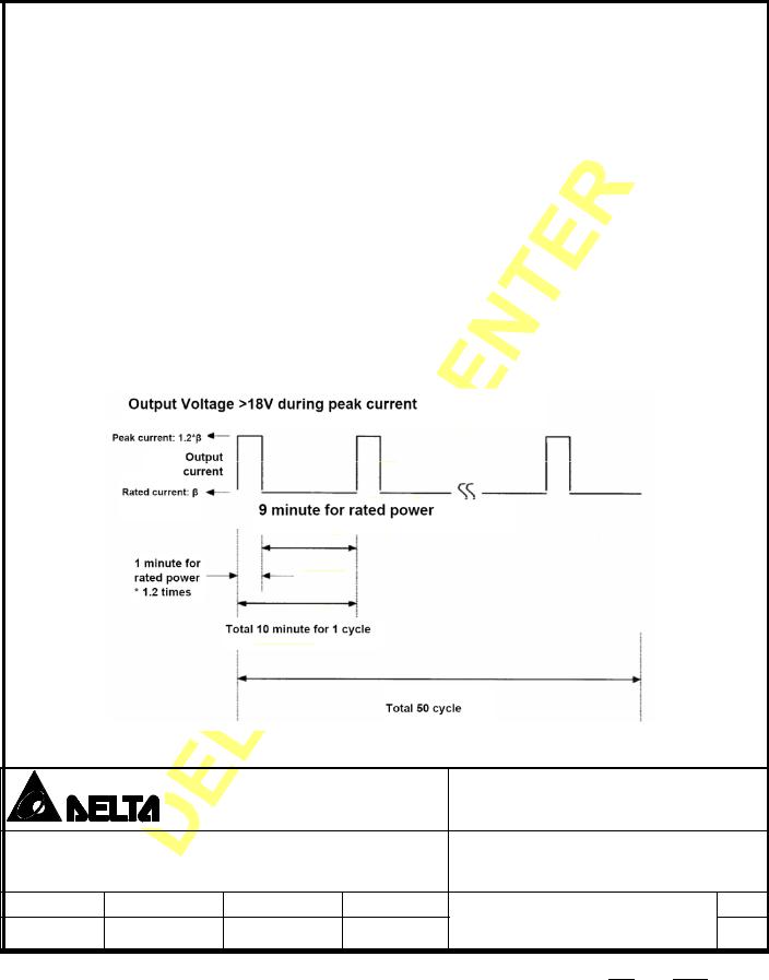
1.2.8Surge load:
The adapter shall support a surge load with 120% of maximum load for 1min , maximun load for 9min and Output Voltage more than 18.0V at input voltage is 100-240Vac
|
DESCRIPTION : |
|
||||
|
DELTA ELECTRONICS, INC. (Electrical Specification) |
|||||
THESE DRAWINGS AND SPECIFICATIONS ARE THE PROPERTY OF DELTA |
MODEL NO. : |
|
||||
ELECTRONICS, INC. AND SHALL NOT BE REPRODUCED OR USED AS THE |
|
|||||
ADP-40PH ABW |
||||||
BASIS FOR THE MANUFACTURE OR SELL OF APPARATUSES OR DEVICES |
||||||
WITHOUT PERMISSION. |
|
|
|
|
||
Date |
Drawn |
Design (EE) |
Design (ME) DOCUMENT NAME. : |
REV. |
||
03/23’10 |
|
|
|
ES-40PH ABW |
00 |
|
|
|
|
||||
File Name:DF-PSLA4V-2R00.DOC |
|
SHEET 6 OF |
16 |
|||
1.2.9Load transient response
The adapter must within regulation when applied a step load from 0A to 100% load at
2.5A/us slew rate , 50% Duty cycle , Frequency be operated 10Hz ~ 10KHz
The output voltage will be performed 18.05 ~ 19.95V
1.2.10Protection
1.2.10.1Over Voltage Protection
The output shall be protected to latch off at over-voltage condition, maximum value can’t be over 27V. That might be return to normal state by AC reset .
1.2.10.2Over Current Protection
The maximum constant current shall be more than 2.1A and be less than 4.5A at 90Vac and 264Vac.
The adaptor shall be auto-recovery.
1.2.10.3Short Circuit protection
Output can be shorted without damage. The adaptor shall be auto-recovery. (It will enter into normal condition when the fault condition is removed.)
1.2.10.4Over Temperature Protection
No deformation and no discoloration on case and will be shut down. That will be return to normal state
by ac reset.
2.Environmental
2.1Temperature
2.1.1Operating
The AC Adapter shall be capable of operating at full load with an ambient temperature range of 0
to +40 .
DESCRIPTION :
DELTA ELECTRONICS, INC. (Electrical Specification)
THESE DRAWINGS AND SPECIFICATIONS ARE THE PROPERTY OF DELTA |
MODEL NO. : |
|
ELECTRONICS, INC. AND SHALL NOT BE REPRODUCED OR USED AS THE |
||
|
BASIS FOR THE MANUFACTURE OR SELL OF APPARATUSES OR DEVICES |
ADP-40PH ABW |
|||||||||
WITHOUT PERMISSION. |
|
|
|
|
|
|
|
|
|
|
|
|
|
|
|
|
|
|
|
|
|
Date |
Drawn |
Design (EE) |
Design (ME) DOCUMENT NAME. : |
|
|
REV. |
||||
03/23’10 |
|
|
|
ES-40PH ABW |
|
|
00 |
|||
|
|
|
|
|
|
|
|
|||
|
|
|
|
|
|
|
|
|
|
|
File Name:DF-PSLA4V-2R00.DOC |
|
SHEET 7 OF |
16 |
|
|
|||||
|
|
|
|
|
|
|
|
|
|
|

2.1.2Shipping/Storage
The AC Adapter shall be capable of withstanding ambient temperature from -30 to +80 .
2.2Humidity
2.2.1Operating
The AC Adapter shall be capable of operation in relative humidity of 8% to 90% relative humidity, non-condensing.
2.2.2Shipping/storage
The AC Adapter shall be capable of withstanding ambient relative humidity of 5% to 95% relative humidity, non-condensing.
2.3Immunity
2.3.1Lightning Surge Immunity
This is to follow the norm of IEC-1000-4-5 Level 3 requirements
L-N 1KV/1.2 * 50uS 5 times No function error.
2.3.2Electric Fast Transients(EFT)
This is to follow the norm of IEC-1000-4-4/1995 (EN 61000-4-4) Level 3 requirements
2.4Electrostatic Discharge (ESD)
This Adapter is capable to withstand ESD test voltage at any point around the enclosure as below.
±15KV air discharge No damage.
±8KV contact discharge No damage.
2.5Surface Temperature rise
Output 40W and ambient 25 ; input voltage 100Vac/240Vac case temperature rise 40 .
|
DESCRIPTION : |
|
||||
|
DELTA ELECTRONICS, INC. (Electrical Specification) |
|||||
THESE DRAWINGS AND SPECIFICATIONS ARE THE PROPERTY OF DELTA |
MODEL NO. : |
|
||||
ELECTRONICS, INC. AND SHALL NOT BE REPRODUCED OR USED AS THE |
|
|||||
ADP-40PH ABW |
||||||
BASIS FOR THE MANUFACTURE OR SELL OF APPARATUSES OR DEVICES |
||||||
WITHOUT PERMISSION. |
|
|
|
|
||
Date |
Drawn |
Design (EE) |
Design (ME) DOCUMENT NAME. : |
REV. |
||
03/23’10 |
|
|
|
ES-40PH ABW |
00 |
|
|
|
|
||||
File Name:DF-PSLA4V-2R00.DOC |
|
SHEET 8 OF |
16 |
|||

2.6Dielectric Withstand Voltage (HI – POT)
Between AC input and secondary AC 3KV test time 1 minute; 100% of line products of this Adapter shall be applied 3000Vac for 2 seconds between AC input terminals and output terminals. Cut off current 3mA.
2.7Leakage Current
(1)Y cap no more than 100pF.
(2)Leakage current no more than 50uA (max.) at 240Vac/50Hz. for Delta production line spec.
2.8Insulation Resistance
The insulation resistance shall be not less than 30M ohms after application of 500Vdc/10mA for 1 minute.
2.9Electromagnetic Interference (EMI)
The adapter shall comply with the following national standards.
(a)FCC Class B
(b)CISPR 22 Class B
(c)VCCI Class B
2.10MTBF
2.10.1 MTBF (Mean-Time-Between-Failures) Calculation
The calculated MTBF shall be 150,000 hours of continuous operation at 25 ,
maximum load and normal voltage.
2.10.2 MTBF Verification
The MTBF shall be verified from life testing performed by factory Quality department.
The operating conditions are: 40 ambient temperature, sea level ,both nominal line voltage ranges(110VAC or 220VAC) and a minimum load of 75% of the maximum load.
|
DESCRIPTION : |
|
||||
|
DELTA ELECTRONICS, INC. (Electrical Specification) |
|||||
THESE DRAWINGS AND SPECIFICATIONS ARE THE PROPERTY OF DELTA |
MODEL NO. : |
|
||||
ELECTRONICS, INC. AND SHALL NOT BE REPRODUCED OR USED AS THE |
|
|||||
ADP-40PH ABW |
||||||
BASIS FOR THE MANUFACTURE OR SELL OF APPARATUSES OR DEVICES |
||||||
WITHOUT PERMISSION. |
|
|
|
|
||
Date |
Drawn |
Design (EE) |
Design (ME) DOCUMENT NAME. : |
REV. |
||
03/23’10 |
|
|
|
ES-40PH ABW |
00 |
|
|
|
|
||||
File Name:DF-PSLA4V-2R00.DOC |
|
SHEET 9 OF |
16 |
|||
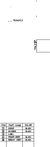
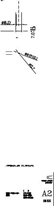
3.Mechanical
3.1Outline Dimension: 85.0*36.0*26.3 mm, Color: BLACK
3.2AC Inlet type: Socket C8 type
3.3DC Cable :
TYPE: UL 1571 20AWG
LENGTH: 1800 mm
3.4 DC Connector Dimension:
OD= 2.5 mm
ID= 0.7 mm
LENGTH= 7.0 mm
|
DESCRIPTION : |
|
||||
|
DELTA ELECTRONICS, INC. (Electrical Specification) |
|||||
THESE DRAWINGS AND SPECIFICATIONS ARE THE PROPERTY OF DELTA |
MODEL NO. : |
|
||||
ELECTRONICS, INC. AND SHALL NOT BE REPRODUCED OR USED AS THE |
|
|||||
ADP-40PH ABW |
||||||
BASIS FOR THE MANUFACTURE OR SELL OF APPARATUSES OR DEVICES |
||||||
WITHOUT PERMISSION. |
|
|
|
|
||
Date |
Drawn |
Design (EE) |
Design (ME) DOCUMENT NAME. : |
REV. |
||
03/23’10 |
|
|
|
ES-40PH ABW |
00 |
|
|
|
|
||||
File Name:DF-PSLA4V-2R00.DOC |
|
SHEET 10 OF |
16 |
|||

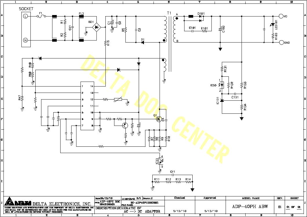
3.Schematic
|
|
FL1 |
|
|
|
6 |
FB101 |
|
|
|
|
|
|
|
|
|
|
|
C103 |
|
|
|
|
|
|
|
1 |
|
|
|
|
|
|
|
|
|
4 |
|
|
ZD31 |
|
|
|
|
|
D32 |
|
|
|
R46 |
|
|
|
|
ZD32 |
|
|
|
|
|
|
|
|
|
|
|
|
||
|
|
|
|
|
|
|
|
|
|
|
|
|
|
|
|
|
3 |
|
|
R40 |
|
|
|
R42 |
NTC31 |
|
|
|
|
|
|
|
|
|
|
|
|
||
|
|
|
|
|
|
|
|
|
|
|
|
|
|
IC32 |
|
|
|
|
|
C41 |
C40 |
C39 |
R41 |
R39 |
R32 |
|
|
|
|
C42 |
Q32 |
R35 |
C31 |
|
|
||||
|
|
|
|||||||
|
|
|
C44 |
C43 |
|
R36 |
|
|
|
|
|
|
|
R38 |
|
|
|
|
|
|
|
|
|
|
|
|
|
|
|

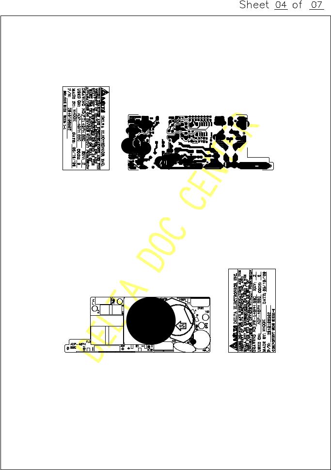
4. PCB Artwork


5.Physical Dimension


 Loading...