


|
COOKERS |
ENGLISH |
|
|
C6N |
|
Instructions for use |
|
Advice for installation |
|
КУХОННЫЕ ПЛИТЫ |
РУССКИЙ |
|
|
СЕРИИ C6N |
|
Инструкция по эксплуатации |
|
Рекомендации по установке |
TG.. 664 GHI TEM.. 664 GHI PG.. 664 GGHI
ENGLISH |
|
• Instructions for use .................................................................................................... |
3 |
• Advice for installation.................................................................................................. |
31 |
РУССКИЙ |
|
• Инструкция по эксплуатации .................................................................................. |
47 |
• Рекомендации по установке..................................................................................... |
75 |
2

ENGLISH
Dear Customer,
Thank you for having purchased and given your preference to our product.
The safety precautions and recommendations reported below are for your own safety and that of others. They will also provide a means by which to make full use of the features offered by your appliance.
Please preserve this booklet carefully. It may be useful in future, either to yourself or to others in the event that doubts should arise relating to its operation.
This appliance must be used only for the task it has explicitly been designed for, that is for
cooking foodstuffs. Any other form of usage is to be considered as inappropriate and therefore dangerous.
The manufacturer declines all responsibility in the event of damage caused by improper, incorrect or illogical use of the appliance.
DECLARATION OF CE CONFORMITY
This cooker has been designed, constructed and marketed in compliance with:
-safety requirements of EEC Directive “Gas” 90/396;
-safety requirements of EEC Directive “Low voltage” 2006/95;
-protection requirements of EEC Directive “EMC” 89/336;
- requirements of EEC Directive 93/68.
3
IMPORTANT SAFEGUARDS AND RECOMMENDATIONS
After removing the appliance from its packing, make sure of its integrity. In case of doubt, please apply to your supplier or to a qualified engineer.
The packing materials (plastic bags, polyfoam, nails, metal strips etc.) must be moved away from the reach of the children as potential sources of danger.
– Do not attempt to alter the technical features of the appliance as this may result very dangerous.
– Do not carry out any operation of cleaning or maintenance without prior disconnection of the appliance from the electric supply.
– Do not line the oven walls with aluminium foil. Do not place baking trays or the drip tray on the base of the oven chamber.
– If you should decide not to use this appliance any longer (or decide to substitute an older model), before disposing of it, it is recommended that it be made inoperative in an appropriate manner in accordance to health and environmental protection regulations, ensuring in particular that all potentially hazardous parts be made harmless, especially in relation to children who could play with old appliances.
– Gas appliances produce heat and humidity in the environment in which they are installed.
Ensure that the cooking area is well ventilated by opening the natural ventilation grilles or by installing an extractor hood connected to an outlet duct.
– If the cooker is used for a prolonged time it may be necessary to provide further ventilation by opening a window or by increasing the suction power of the extractor hood (if fitted).
– Read the instructions carefully before installing and using the appliance.
CAUTION: this apparatus must only be installed in a permanently ventilated room in compliance with the applicable regulations.
4

IMPORTANT INSTRUCTIONS AND ADVICE FOR THE USE OF ELECTRICAL APPLIANCES
The use of any electrical appliance requires the compliance with some basic rules, namely:
–do not touch the appliance with wet or damp hands (or feet)
–do not use the appliance bare feet
–do not allow the appliance to be operated by children or disabled without overseeing.
The manufacturer cannot be deemed responsible for damages caused by wrong or incorrect use.
TIPS FOR THE USER
•During and after use of the cooker, certain parts will become very hot. Do not touch hot parts.
•Keep children away from the cooker when it is in use.
•After use, ensure that the knobs are in position ● (off), and close the main gas delivery valve or the gas cylinder valve.
•In case of difficulty in the gas taps operation, call Service.
FIRST USE OF THE OVEN
It is advised to follow these instructions:
•Furnish the interior of the oven by placing the wire racks as described at chapter “CLEANING AND MAINTENANCE”.
•Insert shelves and tray.
•Turn on the oven, and operate at the maximum temperature in order to eliminate any traces of grease on the heating elements.
•Clean the interior of the oven with cloth soaked in water and detergent (neutral) then dry carefully.
5
1 |
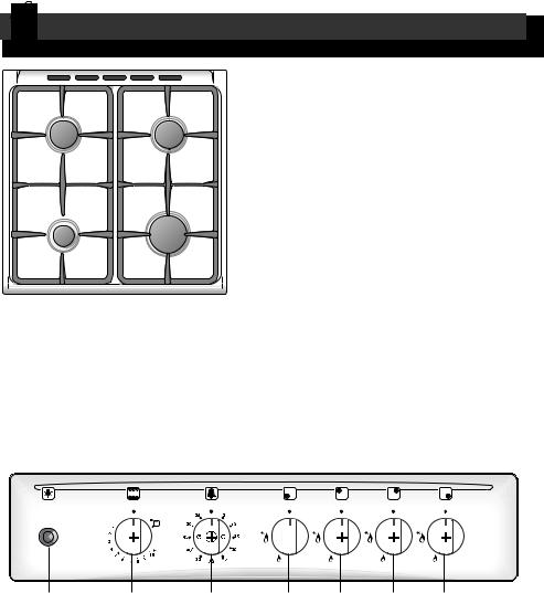
COOKING HOB and CONTROL PANEL |
|
TG.. 664 GHI
2 |
2 |
Important Note: |
The electric ignition is incorporated in the knobs.
The appliance has a safety valve system fitted, the flow of gas will be stopped if and when the flame should accidentally go out.
1 |
The cooker has a gas oven/grill. |
3 |
Fig. 1.1a
TECHNICAL FEATURES - Cooking hob
1. |
Auxiliary burner (A) |
1,00 kW |
2. |
Semi-rapid burner (SR) |
1,75 kW |
3. |
Rapid burner (UR) |
3,00 kW |
Fig. 1.1b
10 9 8 4 5 6 7
CONTROL PANEL |
Pushbutton: |
Controls description |
10. Oven light switch |
4.Front left burner control knob
5.Rear left burner control knob
6.Rear right burner control knob
7.Front right burner control knob
8.Alarm 60’
9.Gas oven/grill control knob
6
|
|
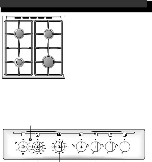
TEM.. 664 GHI |
2 |
2 |
Important Note: |
|
|
The electric ignition is incorporated in |
|
|
the knobs. |
|
|
The appliance has a safety valve |
|
|
system fitted, the flow of gas will be |
|
|
stopped if and when the flame should |
|
|
accidentally go out. |
1 |
3 |
The cooker has an electric fan oven. |
|
||
Fig. 1.2a |
|
|
TECHNICAL FEATURES - Cooking hob |
|
|
1. Auxiliary burner (A) |
1,00 kW |
|
2. Semi-rapid burner (SR) |
1,75 kW |
|
3. Rapid burner (UR) |
3,00 kW |
|
11 |
|
Fig. 1.2b |
10 9 8 4 5 6 7
CONTROL PANEL |
Pilot lamp: |
|
Controls description |
11. Oven thermostat indicator light |
|
4. |
Front left burner control knob |
|
5. |
Rear left burner control knob |
|
6. |
Rear right burner control knob |
|
7. |
Front right burner control knob |
|
8. |
Alarm 60’ |
|
9. |
Oven thermostat knob |
|
10. |
Oven switch knob |
7 |
|
|
|

|
|
PG.. 664 GGHI |
2 |
2 |
Important Note: |
|
|
The electric ignition is incorporated in |
|
|
the knobs. |
|
|
The appliance has a safety valve |
|
|
system fitted, the flow of gas will be |
|
|
stopped if and when the flame should |
|
|
accidentally go out. |
1 |
3 |
The cooker has a gas oven/grill. |
|
||
Fig. 1.3a |
|
|
TECHNICAL FEATURES - Cooking hob |
|
|
1. Auxiliary burner (A) |
1,00 kW |
|
2. Semi-rapid burner (SR) |
1,75 kW |
|
3. Triple-ring burner (TC) |
3,50 kW |
|
Fig. 1.3b
|
|
|
|
|
|
|
|
|
|
|
|
|
|
|
|
|
|
|
|
|
|
|
|
|
|
|
|
|
|
|
|
|
|
|
|
|
|
|
|
|
|
|
|
|
|
|
|
|
|
|
|
|
|
|
|
|
|
|
|
10 |
9 |
8 |
4 |
5 |
6 |
7 |
|||||
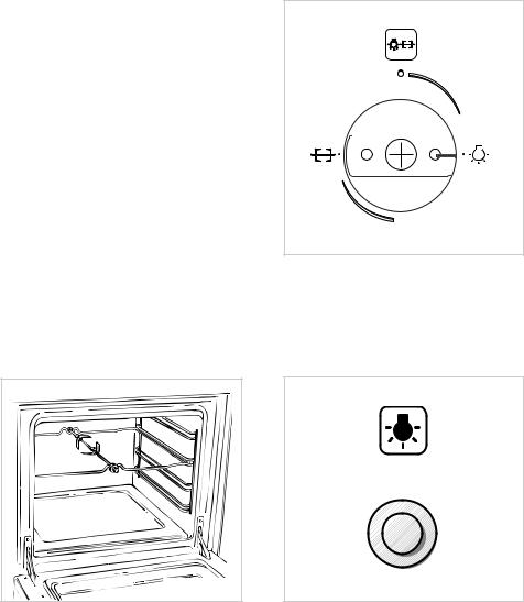
CONTROL PANEL - Controls description
4.Front left burner control knob
5.Rear left burner control knob
6.Rear right burner control knob
7.Front right burner control knob
8.Alarm 60’
9.Oven/grill thermostat knob
10. Rotisserie/oven light switch knob
8
2 |
USE OF COOKING HOB |
|
GAS BURNERS
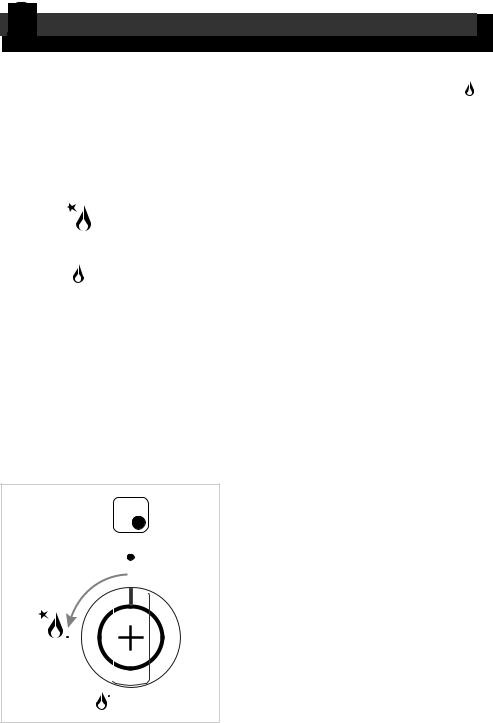
Each burner is controlled by a gas tap which opens and closes the gas supply. Turning the knob so that the indicator line points to the symbols printed on the panel achieves the following functions:
– symbol |
● = off |
– symbol |
= full on |
|
(maximum rate) |
– symbol |
= minimum rate |
The electric ignition is incorporated in
the knobs  symbol beside flame - max. heat/max. gas flow (fig. 2.1).
To reduce the gas flow to minimum, rotate the knob further anti-clockwise to point the indicator towards the small flame symbol.
The maximum aperture position permits rapid boiling of liquids, whereas the minimum aperture position allows slower warming of food or maintaining boiling conditions of liquids.
Other intermediate operating adjustments can be achieved by positioning the indicator between the maximum and minimum aperture positions, and never between the maximum aperture and closed positions.
N.B. When the cooktop is not being used, set the gas knobs to their closed positions and also close the cock valve on the gas bottle or the main gas supply line.
Fig. 2.1
9
LIGHTING GAS BURNERS FITTED WITH SAFETY VALVE DEVICE
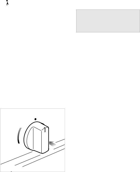
To ignite the burner, the following instructions are to be followed:
1)Press in the corresponding knob and turn counter-clockwise (Fig. 2.2) to the full flame position marked by the
 ) symbol (Fig. 2.1) and hold the knob in until the flame has been lit. In the case of a mains failure light the burner with a match or lighted taper.
2)Wait for about ten seconds after the gas burner has been lit before letting go of the knob (valve activation delay);
3)Adjust the gas valve to the desired position.
If the burner flame should go out for some reason, the safety valve will automatically stop the gas flow.
To re-light the burner, return the knob to the closed ● position, wait for at least 1 minute and then repeat the lighting procedure.
If your local gas supply makes it difficult to light the burner with the knob set to maximum, set the knob to minimum and repeat the operation.
In the case of a mains failure light the burner with a match or lighted taper.
Caution!
The cooking hob becomes very hot during operation.
Keep children well out of reach.
Fig. 2.2 |
10 |
CHOICE OF THE BURNER
On the control panel, near every knob, there is a diagram that indicates which burner is controlled by that knob.
The suitable burner must be chosen according to the diameter and the capacity used.
As an indication, the burners and the pots must be used in the following way:
DIAMETERS OF PANS WHICH MAY BE
USED ON THE HOBS
BURNERS |
MINIMUM |
MAX. |
Auxiliary |
12 cm |
14 cm |
Semirapid |
16 cm |
24 cm |
Rapid |
24 cm |
26 cm |
Triple-ring |
26 cm |
28 cm |
do not use pans with concave or convex bases
It is important that the diameter of the pot be suitable to the potentiality of the burner so as not to compromise the high output of the burners and therefore energy waste.
A small pot on a large burner does not give you a boiling point in a shorten amount of time since the capacity of heat absorption of a liquid mass depends on the volume and the surface of the pot.
GRATE FOR SMALL PANS
This grate is to be placed on top of the (smaller) auxiliary burner when using small diameter pans, in order to prevent them from tipping over.
Fig. 2.4
Fig. 2.3
11
3 |
GAS OVEN - TG.. 664 GHI , PG.. 664 GGHI |
Attention: the oven door becomes very hot during operation.
Keep children away.
(Models with glass lid) Attention: The cooker lid must be kept open when the gas oven is in use.
GENERAL FEATURES
The cooker is furnished completely clean; it is advisable, however, upon first use, to turn the oven on to the maximum
temperature (position  ) to eliminate possible traces of grease from the oven burner.
The gas oven is provided with:
–One gas burner (3700 W), located at the bottom, providing safety device and automatic ignition.
–One gas grill (2500 W), placed on the top, providing self-ignition and safety device.
WARNING:
The door is hot, use the handle.
During use the appliance becomes hot. Care should be taken to avoid touching heating elements inside the oven.
Fig. 3.1
12
OVEN BURNER
It carries out normal “oven cooking”.
The gas flow to the burner is regulated by a thermostat which allow to maintain the oven temperature constant.
The control of the temperature is assured by a thermostatic probe positioned inside the oven.
The probe must be always kept in its housing, in a clean condition, as an incorrect position or encrustment may cause an alteration in the control of the temperature.
Moreover, the thermostat is fitted with a safety valve which automatically shuts off the gas supply when the flame goes out.
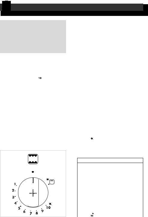
THERMOSTAT
The numbers 1 to 10 printed on the knob (fig. 3.1) indicate the increasing oven temperature value (see table below).
The temperature is constantly maintained on the set value.
Symbol near position 10 indicates that the electric ignition is incorporated in the knob and is activated by the knob itself.
THERMOSTAT GRADE TABLE
Thermostat |
Oven |
indicator |
temperature |
1 |
150 °C |
2 |
165 °C |
3 |
180 °C |
4 |
195 °C |
5 |
210 °C |
6 |
225 °C |
7 |
240 °C |
8 |
255 °C |
9 |
270 °C |
|
285 °C |
IGNITION OF THE OVEN BURNER
To ignite the oven burner:
1 – Open the oven door to the full extent.
WARNING: Risk of explosion! The oven door must be open during this operation.
2 – Lightly press and turn the thermostat knob anti-clockwise to max position
“  ” (fig. 3.1).
Press the knob right down to prime the electric ignition.
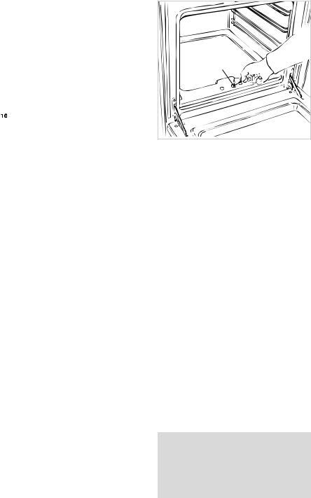
In case of power cut, press the knob and immediately approach a lighted match to the opening “A” (fig. 3.2).
Never continue this operation for more than 15 seconds. If the burner has still not ignited, wait for about 1 minute prior to repeating the ignition.
3 – After lighting the burner, wait a few seconds before releasing the knob (until the safety valve stays open).
4 – Gently close the oven door and set the oven control knob to the required temperature.
If the flame extinguishes for any reason, the safety valve will automatically shut off the gas supply to the burner.
To re-light the burner, first turn the oven control knob to position ●, wait for at least 1 minute and then repeat the lighting procedure.
ATTENTION: Never turn the thermostat before approaching a flame to the hole “A” of the floor of the oven.
A |
Fig. 3.2 |
Remember to keep children away from the appliance when you use the grill or oven, since these parts become very hot.
13
OVEN COOKING
Before introducing the food, preheat the oven to the desired temperature.
For a correct preheating operation, it is advisable to remove the tray from the oven and introduce it together with the food, when the oven has reached the desired temperature.
Check the cooking time and turn off the oven 5 minutes before the theoretical time to recuperate the stored heat.
COOKING EXAMPLES
Temperatures and times are approximate as they vary depending on the quality and amount of food.
Remember to use ovenproof dishes and to adjust the oven temperature during cooking if necessary.
DISHES Temperature
Lasagne |
220° |
Baked pasta |
220° |
Pizza |
225° |
Creole rice |
225° |
Baked onions |
190° |
Spinach crêpes |
185° |
Potatoes baked in milk |
185° |
Stuffed tomatoes |
180° |
Cheese soufflé |
170° |
Roast veal |
180° |
Grilled veal chops |
210° |
Chicken breasts with tomato |
180° |
Grilled chicken - roast chicken |
190° |
Veal loaf |
175° |
Roast beef |
170° |
Fillet of sole |
175° |
Aromatic hake |
170° |
Beignets |
160° |
Ring cake |
150° |
Plum tart |
170° |
Jam tartlets |
160° |
Sponge cake |
170° |
Sweet dough |
160° |
Sweet puffs |
170° |
Plain sponge cake |
170° |
The oven accessories can bear loads up to 6 kg.
Distribute the loads uniformly.
14
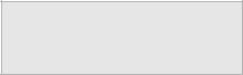
IGNITION OF THE GRILL BURNER
To light the grill burner operate as follows:
ATTENTION: Never turn the thermostat before opening the oven door.
1)Open the oven door to the full extent.
WARNING: Risk of explosion! The oven door must be open during this operation.
2)Lightly press and turn the thermostat knob clockwise to the 
 , position (fig. 3.3).
3)Press the knob firmly until the burner lights.
Never continue this operation for more than 15 seconds. If the burner has still not ignited, wait for about 1 minute prior to repeating the ignition.
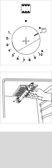
In case of mains failure, press the knob firmly and put a lighted match or taper to the pipe of the burner (fig. 3.4).
4)After lighting the burner, wait a few seconds before releasing the knob (until the safety valve stays open).
Do not close completely the oven door. The grill must always be used with the oven door slightly open (Fig. 3.5).
The oven door must always be kept half-open when the grill is in operation. See specific instructions in the section ‘USE OF THE GRILL’.
If the flame extinguishes for any reason, the safety valve will automatically shut off the gas supply to the burner.
To re-light the burner, first turn the oven control knob to position λ, wait for at least 1 minute and then repeat the lighting procedure.
Fig. 3.3
Fig. 3.4
Very important: the grill must always be used with the oven door ajar and with shield “A” mounted (Fig. 3.5).
Remember to keep children away from the appliance when you use the grill or oven, since these parts become very hot.
15

USE OF THE GRILL
Very important: the grill must always be used with the oven door slightly open and with shield "A” mounted (Fig. 3.5).
Mount shield “A” (fig. 3.5) which serves to protect the control panel from the heat.
Turn on the grill, as explained in the preceding paragraphs and let the oven preheat for about 5 minutes with the door ajar.
Introduce the food to be cooked, positioning the rack as close to the grill as possible.
The dripping pan should be placed under the rack to catch the cooking juices and fats.
Note: It is recommended that you do not grill for longer than 30 minutes at any one time.
Attention: the oven door becomes very hot during operation.
Keep children away
ROTISSERIE
PG.. 664 GGHI models are supplied with the rotisserie.
OPERATING THE ROTISSERIE - PG.. 664 GGHI
The rotisserie motor is operated by a switch knob  (fig. 3.6).
This is used for spit roasting under the grill and comprises:
– an electric motor fitted to the rear of the oven
– a stainless steel skewer provided with slide-out heatless handgrip and two sets of adjustable forks
– a skewer support to be fitted in the middle runner.
The rotation direction of the rotisserie can be either clokwise or counter-clock- wise.
A |
|
ZONE |
|
HOT |
|
Fig. 3.5 |
Fig. 3.6 |
16 |
|
USE OF THE ROTISSERIE
PG.. 664 GGHI - (fig. 3.7):
–Insert the tray into the lowest rack holders of the oven and insert the rod support into the intermediate rack holders.
–Put the meat to be cooked onto the rod, being careful to secure it in the center with the special forks.
–Insert the rod into the motor opening and rest it onto the support of the spit collar; then remove the grip by turning it to the left.
– Fit the heat shield and switch on the grill and turnspit.
The rotation direction of the rotisserie can be either clokwise or counterclockwise.
Very important: the rotisserie must always be used with the oven door ajar and with shield “A” mounted.
Attention: the oven door becomes very hot during operation.
Keep children away.
It is recommended that you do not grill for longer than 30 minutes at any one time.
Fig. 3.7 |
OVEN LIGHT
The cooker is equipped with a light that illuminates the oven to enable visually controlling the food that is cooking.
Models with switch knob (PG.. 664 GGHI)
To light the oven lamp turn the knob fig. fig. 3.8, to the symbol  .
.
Fig. 3.8
Models with push button (TG.. 664 GHI)
The oven lamp is operated by pressing the relative push button  (fig. 3.9).
Fig. 3.9
17

4 |
FAN ASSISTED OVEN - TEM.. 664 GHI |
|
Attention: the oven door becomes very hot during operation.
Keep children away.
Attention: The cooker lid must be kept open when the electric oven is in use.
WARNING: The door is hot, use the handle. During use the appliance becomes hot. Care should be taken to avoid touching heating elements inside the oven.
FAN ASSISTED OVEN
– Lower element |
1400 W |
– Upper element |
1000 W |
– Grill element |
2000 W |
GENERAL FEATURES
As the name implies, this oven features a number of special characteristics from the functional point of view.
4 different thermostatic control functions are available to satisfy all cooking requirements, provided by 3 heating elements.
NOTE:
Upon first use, to eliminate possible traces of grease on the heating elements, it is advisable to operate the oven at the maximum temperature:
-for 60 minutes in the position 
 (thermostat knob on position 250°C);
- for 15 minutes in the position |
(ther- |
mostat knob on position 175°C). |
|
OPERATING PRINCIPLES
Heating and cooking in the 4-function ventilated oven are obtained:
a. by natural convection
The heat is produced by the upper and lower heating elements.
b.by forced convection
The heat produced by the lower and upper heating elements is distributed in the oven by the fan.
Several dishes can be cooked at the same time.
c.by radiation and ventilation
The heat irradiated by the infrared grill resistance is distributed in the oven by the fan.
d.by radiation
The heat is radiated by the infrared grill resistance.
e.by ventilation
The food is defrosted by using the fan only function without heat.
18
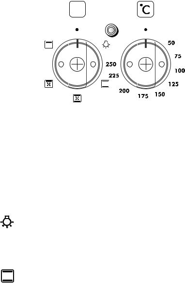
Fig. 4.1 |
Fig. 4.2 |
THERMOSTAT (Fig. 4.2)
To turn on the heating elements of the oven, set the switch knob on the desired program and the thermostat knob onto the desired temperature (from 50° to 250° C).
FUNCTION SELECTOR KNOB (fig. 4.1)
Rotate the knob clockwise to set the oven for one of the following functions:
OVEN LIGHT
By setting the knob to this position, only the oven light comes on.
The light remains on whilst any of the cooking modes are selected.
TRADITIONAL CONVECTION COOKING
The upper and lower heating elements are switched on. The heat is diffused by natural convection and the temperature must be set between 50° C and 250° C.
It is necessary to preheat the oven before adding the foods to be cooked.
Recommended for:
For foods which require the same cooking temperature both internally and externally, i. e. roasts, spare ribs, meringue, etc.
19

CONVECTION COOKING WITH VENTILATION
The upper and lower heating elements and the fan come on. The heat coming from above and below is diffused by forced convection. The temperature must be set to between 50° and 250°C via the thermostat knob.
Recommended for:
Voluminous dishes and large quantities which require the same degree of cooking both inside and out, for example rolled roasts, turkey, roast legs, cakes etc.
DEFROSTING FROZEN FOODS
With the thermostat knob on position “●” only the oven fan is on. The defrosting is done by simple ventilation without heat.
Recommended for:
To rapidly defrost frozen foods; 1 kilogram requires about one hour. The defrosting times vary according to the quantity and type of foods to be defrosted.
VENTILATED GRILL COOKING
The infrared grill and the fan come on.
The heat is diffused mainly by radiation and the fan then distributes it all over the oven. The oven must be used with the door closed and the temperature can be regulated via
the thermostat knob to between 50° and 175 °C.
For cooking hints, see the chapter “GRILLING AND COOKING AU GRATIN”.
It is recommended that you do not grill for longer than 30 minutes at any one time. Attention: the oven door becomes very hot during operation.
Keep children away.
Recommended for:
Grilling where quick browning on the outside is required to keep the juices in. For example: veal fillets, chops etc.
GRILLING
The infra-red heating element is switched on. The heat is diffused by radiation.
Use with the oven door closed and the thermostat knob to position 225°C for 15 minutes,
then to position 175°C.
For correct use see chapter “USE OF THE GRILL”.
Grilling with the oven door closed.
Attention: the oven door becomes very hot during operation. Keep children away. It is recommended that you do not grill for longer than 30 minutes at any one time.
Recommended for:
20 Intense grilling, browning, cooking au gratin and toasting etc.
COOKING ADVICE
STERILIZATION
Sterilization of foods to be conserved, in full and hermetically sealed jars, is done in the following way:
a. Set the switch to position 
b. Set the thermostat knob to position 175 °C and preheat the oven.
c. Fill the dripping pan with hot water.
d. Set the jars onto the dripping pan making sure they do not touch each other and the door and set the thermostat knob to position 130 °C.
When sterilization has begun, that is, when the contents of the jars start to bubble, turn off the oven and let cool.
GRILLING AND “AU GRATIN”
Grilling may be done without the roasting jack on position of the switch, because the hot air completely envelops the food that is to be cooked.
Set the thermostat to position 175 °C and after having preheated the oven, simply place the food on the rack.
Close the door and let the oven operate with the thermostat on position between 50 and 175 °C, until grilling is done.
Adding a few dabs of butter before the end of the cooking time gives the golden “au gratin” effect.Note: It is recommended that you do not grill for longer than 30 minutes at any one time.
Attention: the oven door becomes very hot during operation.
Keep children away.
REGENERATION
Set the switch to position  and the thermostat knob to position 150° C. Bread becomes fragrant again if wet with a few drops of water and put into the oven for about 10 minutes at the highest temperature.
ROASTING
To obtain classical roasting, it is necessary to remember:
–that it is advisable to maintain a temperature between 180 and 200 °C.
–that the cooking time depends on the quantity and the type of foods.
TRADITIONAL GRILLING
Turn on the grill, as explained in the preceding paragraphs and let the oven preheat for about 5 minutes with the door closed.
Introduce the food to be cooked, positioning the rack as close to the grill as possible.
The dripping pan should be placed under the rack to catch the cooking juices and fats.
Grilling with the oven door closed.
Grilling with the oven door closed and do not for longer than 30 minutes at any one time.
Attention: the oven door becomes very hot during operation.
Keep children away.
21
SIMULTANEOUS COOKING OF DIFFERENT FOODS
With the function selector in position
 the ventilated oven allows you to cook different types of food at the same
time.
Fish, cakes and meat can be cooked together without the smells and flavours mixing.
The only precautions required are the following:
– The cooking temperatures must be as close as possible with a maximum difference of 20° - 25°C between the different foods.
– Different dishes must be placed in the oven at different times according to the cooking time required for each one. This type of cooking obviously provides a considerable saving on time and energy.
22
OVEN COOKING
Before introducing the food, preheat the oven to the desired temperature.
For a correct preheating operation, it is advisable to remove the tray from the oven and introduce it together with the food, when the oven has reached the desired temperature.
Check the cooking time and turn off the oven 5 minutes before the theoretical time to recuperate the stored heat.
COOKING EXAMPLES
Temperatures and times are approximate as they vary depending on the quality and amount of food.
Remember to use ovenproof dishes and to adjust the oven temperature during cooking if necessary.
DISHES Temperature
Lasagne |
220° |
Baked pasta |
220° |
Pizza |
225° |
Creole rice |
225° |
Baked onions |
190° |
Spinach crêpes |
185° |
Potatoes baked in milk |
185° |
Stuffed tomatoes |
180° |
Cheese soufflé |
170° |
Roast veal |
180° |
Grilled veal chops |
210° |
Chicken breasts with tomato |
180° |
Grilled chicken - roast chicken |
190° |
Veal loaf |
175° |
Roast beef |
170° |
Fillet of sole |
175° |
Aromatic hake |
170° |
Beignets |
160° |
Ring cake |
150° |
Plum tart |
170° |
Jam tartlets |
160° |
Sponge cake |
170° |
Sweet dough |
160° |
Sweet puffs |
170° |
Plain sponge cake |
170° |
5 |
MINUTE COUNTER |
|
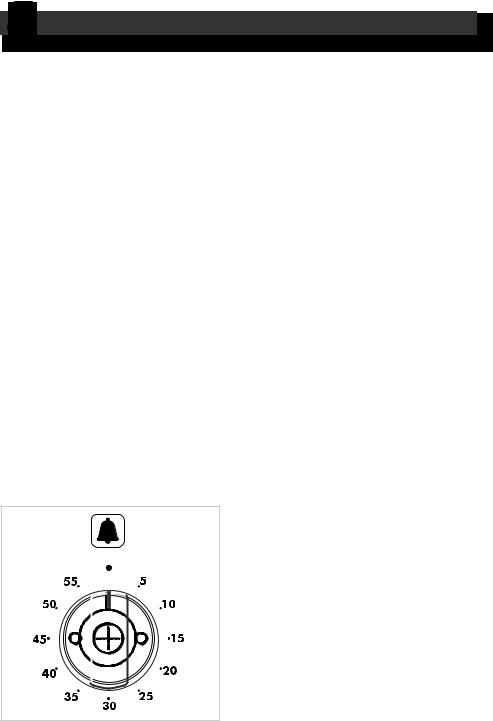
MINUTE COUNTER (Fig. 5.1)
The minute counter is a timed acoustic warning device which can be set for a maximum of 60 minutes.
The knob (Fig. 5.1) must be rotated clockwise as far as the 60 minute position and then set to the required time by rotating it anticlockwise.
Fig. 5.1 |
23 |
|
6 |
CLEANING AND MAINTENANCE |
|
GENERAL ADVICE
–Before any operation of cleaning and maintenance disconnect the appliance from the electrical network.
– When the appliance is not being used, it is advisable to keep the gas tap closed.
– Every now and then check to make sure that the flexible tube that connects the gas line or the gas cylinder to the appliance is in perfect condition and eventually substitute it if it shows signs of wearing or damage.
– Do not use cleaning products with a chlorine or acidic base.
–If a gas tap jams, do not try to force it. Seek technical assistance.
R |
D |
S |
Fig. 6.1 |
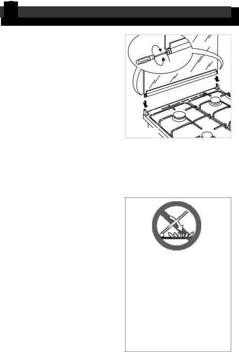
GLASS LID
(Models: TG.. 664 GHI,TEM.. 664 GHI)
For cleaning purposes, the lid can be easily removed upwards once taken to the upright position.
Should the hinges slip off, replace them in their housing being careful that:
– The right housing must receive the hinge marked “D” while the left housing must receive the hinge marked “S” (Fig. 6.1).
REGULATING OF THE BALANCE
Lower the lid and check the correct balance. While opened at 45° it should hang up.
The springs of the hinges can be adjusted if necessary by turning the screws “R” clockwise (fig. 6.1).
24
Do not shut lid when burner alight.
ATTENTION
-Do not lower the glass lid when burners are still hot or when the oven is working or still hot.
-Do not lay on the glass lid hot pans and heavy kitchen utensils.
-Dry off any liquid which may have spilt on the cover before opening it.

ENAMELLED PARTS
All the enamelled parts must be cleaned with a sponge and soapy water or other non-abrasive products.
Dry preferably with a soft cloth.
Acidic substances like lemon juice, tomato sauce, vinegar etc. can damage the enamel if left too long.
Do not use a steam cleaner because the moisture can get into the appliance thus make it unsafe.
STAINLESS STEEL SURFACES
(Model: PG.. 664 GGHI)
CAUTION
The stainless steel front panels on this cooker (facia, oven door, drawer or storage compartment) are protected by a finger-print proof lacquer.
To avoid damaging this lacquer, do not clean the stainless steel with abrasive cleaners or abrasive cloths or scouring pads.
ONLY SOAP/WARM WATER MUST BE USED TO CLEAN THE STAINLESS STEEL SURFACES.
STAINLESS STEEL, ALUMINIUM PARTS AND SILKSCREEN PRINTED SURFACES
Clean using an appropriate product. Always dry thoroughly.
IMPORTANT: these parts must be cleaned very carefully to avoid scratching and abrasion. You are advised to use a soft cloth and neutral soap.
CAUTION:
Do not use abrasive substances or non-neutral detergents.
Note: Regular use could yellow the surfaces around the burners (due to oxidation of the surface of the stainless steel) because of the high flame temperature.
Do not use a steam cleaner because the moisture can get into the appliance thus make it unsafe.
GAS TAPS
In the event of operating faults in the gas taps, call the Service Department.
REPLACING THE OVEN LIGHT BULB
Disconnect the cooker from the electrical network.
When the oven is cool unscrew and replace the bulb with another one resistant to high temperatures (300°C), voltage 230 V (50 Hz), 15 W, E14.
25
BURNERS
They can be removed and washed with soapy water only.
They will remain always perfect if cleaned with products used for silverware.
After cleaning or wash, check that burn- er-caps and burner-heads are dry before placing them in the respective housings.
It is very important to check that the burner flame distributor and the cap has been correctly positioned - failure to do so can cause serious problems.
Note: To avoid damage to the electric ignition do not use it when the burners are not in place.
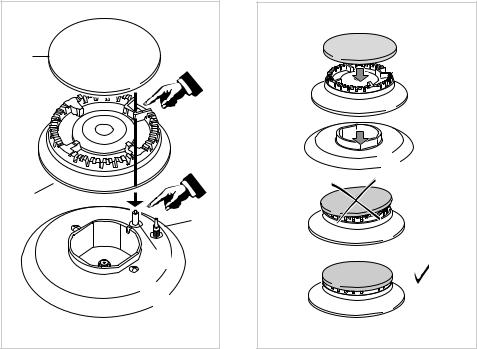
CORRECT REPLACEMENT OF THE BURNERS
It is very important to check that the burner flame distributor F and the cap C has been correctly positioned (see fig. 6.2 - 6.3) - failure to do so can cause serious problems.
Check that the electrode “S” (fig. 6.2) is always clean to ensure trouble-free sparking.
Check that the probe “T” (fig. 6.2) next to each burner is always clean to ensure correct operation of the safety valves.
Both the probe and ignition plug must be very carefully cleaned.
C |
|
F |
|
|
T |
|
S |
Fig. 6.2 |
Fig. 6.3 |
26 |
|
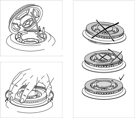
Triple ring burner (models with triple ring burner)
The triple ring burner must be correctly positioned (see fig. 6.4); the burner rib must be enter in their logement as shown by the arrow.
Then position the cap A and the ring B (fig. 6.5 - 6.6). The burner correctly positioned must not rotate (fig. 6.5).
Fig. 6.4
A B
Fig. 6.5 |
Fig. 6.6 |
|
27 |

REMOVING THE OVEN DOOR Type A
The oven door can easily be removed as follows:
–Open the door to the full extent (fig. 6.7A).
–Attach the retaining rings to the hooks on the left and right hinges (fig. 6.7B).
–Hold the door as shown in fig. 6.7.
–Gently close the door and withdraw the lower hinge pins from their location (fig. 6.7C).
–Withdraw the upper hinge pins from their location (fig. 6.7D).
–Rest the door on a soft surface.
–To replace the door, repeat the above steps in reverse order.
28 |
Fig. 6.7 |
|
Fig. 6.7A
Fig. 6.7B
Fig. 6.7C |
Fig. 6.7D
 Loading...