

Dell Latitude 5289 User Manual

Latitude 5289 2-in-1
Owner's Manual
Regulatory Model: P29S
Regulatory Type: P29S001

Notes, cautions, and warnings
NOTE: A NOTE indicates important information that helps you make better use of your product.
CAUTION: A CAUTION indicates either potential damage to hardware or loss of data and tells you how to avoid the problem.
WARNING: A WARNING indicates a potential for property damage, personal injury, or death.
© 2017 Dell Inc. or its subsidiaries. All rights reserved. Dell, EMC, and other trademarks are trademarks of Dell Inc. or its subsidiaries. Other trademarks
may be trademarks of their respective owners.
2017 - 02
Rev. A00

Contents
1 Working on your computer............................................................................................................................. 7
Safety instructions............................................................................................................................................................. 7
Before working inside your computer..............................................................................................................................7
Turning o your computer — Windows 10.....................................................................................................................8
After working inside your computer.................................................................................................................................8
2 Removing and installing components.............................................................................................................9
Screw size list.....................................................................................................................................................................9
Recommended tools..........................................................................................................................................................9
Micro Secure Digital (SD) Card........................................................................................................................................ 9
Removing the Micro Secure Digital (SD) Card....................................................................................................... 10
Installing the Micro Secure Digital (SD) Card..........................................................................................................10
Subscriber Identity Module (SIM) Card.........................................................................................................................10
Removing the micro SIM card or the micro SIM card tray....................................................................................10
Base cover.........................................................................................................................................................................10
Removing the base cover..........................................................................................................................................10
Installing the base cover.............................................................................................................................................11
Battery............................................................................................................................................................................... 12
Lithium-ion battery precautions................................................................................................................................12
Removing the battery................................................................................................................................................ 12
Installing battery..........................................................................................................................................................13
PCIe Solid State Drive (SSD).......................................................................................................................................... 13
Removing the NVMe SSD card................................................................................................................................ 13
Installing the NVMe SSD........................................................................................................................................... 14
WLAN card........................................................................................................................................................................ 14
Removing the WLAN card.........................................................................................................................................14
Installing the WLAN card...........................................................................................................................................15
WWAN card.......................................................................................................................................................................15
Removing the WWAN card....................................................................................................................................... 15
Installing the WWAN card..........................................................................................................................................16
Power board...................................................................................................................................................................... 16
Removing the power board....................................................................................................................................... 16
Installing the power board..........................................................................................................................................17
Speaker.............................................................................................................................................................................. 17
Removing the speaker module..................................................................................................................................17
Installing the speaker module....................................................................................................................................19
Fingerprint Board..............................................................................................................................................................19
Removing the ngerprint reader board....................................................................................................................19
Installing the ngerprint reader board..................................................................................................................... 20
LED Board.........................................................................................................................................................................20
Removing the LED board..........................................................................................................................................20
Installing the LED board.............................................................................................................................................21
Smart Card Cage..............................................................................................................................................................21
Contents
3

Removing the smart card cage................................................................................................................................22
Installing the smart card cage.................................................................................................................................. 23
Heat Sink...........................................................................................................................................................................23
Removing heat sink assembly...................................................................................................................................23
Installing heat sink assembly.....................................................................................................................................24
Display Assembly..............................................................................................................................................................24
Removing the display assembly................................................................................................................................24
Installing the display assembly.................................................................................................................................. 27
Removing dummy SIM card tray....................................................................................................................................27
System Board...................................................................................................................................................................28
Removing system board............................................................................................................................................28
Installing system board...............................................................................................................................................31
Real time clock (RTC)......................................................................................................................................................31
Removing the real time clock (RTC)....................................................................................................................... 32
Installing real time clock (RTC).................................................................................................................................32
Keyboard........................................................................................................................................................................... 33
Removing keyboard assembly.................................................................................................................................. 33
Removing keyboard from the keyboard tray.......................................................................................................... 34
Installing keyboard to the keyboard tray................................................................................................................. 35
Installing keyboard assembly.....................................................................................................................................35
Display Panel.....................................................................................................................................................................36
Removing the display panel...................................................................................................................................... 36
Installing the display panel.........................................................................................................................................38
G-sensor board.................................................................................................................................................................38
Removing the G-sensor board.................................................................................................................................38
Installing the G-sensor board .................................................................................................................................. 39
Camera..............................................................................................................................................................................39
Removing the camera............................................................................................................................................... 39
Installing the camera..................................................................................................................................................40
Palmrest............................................................................................................................................................................40
Replacing palm rest ................................................................................................................................................... 41
3 Technology and components........................................................................................................................43
Power adapter..................................................................................................................................................................43
Processors........................................................................................................................................................................ 43
Identifying processors in Windows 10......................................................................................................................43
Verifying processor usage in task manager............................................................................................................ 44
Verifying processor usage in resource monitor...................................................................................................... 44
Chipset.............................................................................................................................................................................. 45
Identifying chipset in device manager on Windows 10..........................................................................................45
Memory features..............................................................................................................................................................46
Verifying system memory in setup...........................................................................................................................46
Verifying system memory ........................................................................................................................................ 46
Testing memory using ePSA.....................................................................................................................................47
Display................................................................................................................................................................................47
Display options............................................................................................................................................................47
Identifying display adapter.........................................................................................................................................47
Contents
4

Changing the screen resolution................................................................................................................................47
Connecting to external display devices...................................................................................................................48
Camera features...............................................................................................................................................................48
Identifying the camera in Device Manager on Windows 10..................................................................................48
Starting the camera (Windows 7, 8.1 and 10)......................................................................................................... 48
Starting the camera application...............................................................................................................................49
Hard drive......................................................................................................................................................................... 50
Storage options..........................................................................................................................................................50
Identifying the storage device in the BIOS.............................................................................................................50
Identifying storage device in Windows 10...............................................................................................................50
USB features....................................................................................................................................................................50
USB 3.0/USB 3.1 Gen 1 (SuperSpeed USB)...........................................................................................................50
Speed........................................................................................................................................................................... 51
Applications.................................................................................................................................................................52
Compatibility...............................................................................................................................................................52
HDMI 1.4............................................................................................................................................................................52
HDMI 1.4 Features......................................................................................................................................................53
Advantages of HDMI.................................................................................................................................................53
4 System specications..................................................................................................................................54
System specications......................................................................................................................................................54
Processor specications................................................................................................................................................. 54
Memory specications.................................................................................................................................................... 55
Video specications.........................................................................................................................................................55
Display specications...................................................................................................................................................... 55
Audio specications.........................................................................................................................................................55
Storage options................................................................................................................................................................56
Communication specications....................................................................................................................................... 56
Near eld communication (NFC) specications..........................................................................................................56
Fingerprint reader specications....................................................................................................................................56
Ports and connector specications............................................................................................................................... 57
Touchpad specications.................................................................................................................................................. 57
Camera specications..................................................................................................................................................... 57
IR camera specications..................................................................................................................................................57
Display specications.......................................................................................................................................................58
AC adapter specications...............................................................................................................................................58
Battery specications......................................................................................................................................................59
Physical specications.....................................................................................................................................................60
Environmental specications..........................................................................................................................................60
5 System setup...............................................................................................................................................62
Boot menu........................................................................................................................................................................ 62
Navigation keys................................................................................................................................................................63
System setup options......................................................................................................................................................63
General screen options....................................................................................................................................................63
System Conguration screen options........................................................................................................................... 64
Video screen options.......................................................................................................................................................66
Contents
5

Security screen options...................................................................................................................................................66
Secure Boot screen options........................................................................................................................................... 68
Intel software guard extensions screen options...........................................................................................................68
Performance screen options.......................................................................................................................................... 69
Power management screen options..............................................................................................................................69
POST behavior screen options........................................................................................................................................71
Manageability....................................................................................................................................................................72
Virtualization support screen options............................................................................................................................ 72
Wireless screen options...................................................................................................................................................73
Maintenance screen options...........................................................................................................................................73
System logs screen options............................................................................................................................................ 74
Updating the BIOS in Windows .....................................................................................................................................74
System and setup password...........................................................................................................................................74
Assigning a system password and setup password............................................................................................... 75
Deleting or changing an existing system and/or setup password........................................................................75
6 Troubleshooting........................................................................................................................................... 76
Enhanced Pre-Boot System Assessment (ePSA) diagnostics................................................................................... 76
Running the ePSA diagnostics................................................................................................................................. 76
Diagnostic LED................................................................................................................................................................. 76
7 Contacting Dell............................................................................................................................................ 78
6
Contents

Working on your computer
Safety instructions
Use the following safety guidelines to protect your computer from potential damage and to ensure your personal safety. Unless otherwise
noted, each procedure included in this document assumes that the following conditions exist:
• You have read the safety information that shipped with your computer.
• A component can be replaced or, if purchased separately, installed by performing the removal procedure in reverse order.
WARNING: Disconnect all power sources before opening the computer cover or panels. After you nish working inside the
computer, replace all covers, panels, and screws before connecting to the power source.
WARNING: Before working inside your computer, read the safety information that shipped with your computer. For additional
safety best practices information, see the Regulatory Compliance Homepage at www.dell.com/regulatory_compliance
CAUTION: Many repairs may only be done by a certied service technician. You should only perform troubleshooting and simple
repairs as authorized in your product documentation, or as directed by the online or telephone service and support team.
Damage due to servicing that is not authorized by Dell is not covered by your warranty. Read and follow the safety instructions
that came with the product.
1
CAUTION: To avoid electrostatic discharge, ground yourself by using a wrist grounding strap or by periodically touching an
unpainted metal surface that is grounded to ground yourself before you touch the computer to perform any disassembly tasks.
CAUTION: Handle components and cards with care. Do not touch the components or contacts on a card. Hold a card by its
edges or by its metal mounting bracket. Hold a component such as a processor by its edges, not by its pins.
CAUTION: When you disconnect a cable, pull on its connector or on its pull-tab, not on the cable itself. Some cables have
connectors with locking tabs; if you are disconnecting this type of cable, press in on the locking tabs before you disconnect the
cable. As you pull connectors apart, keep them evenly aligned to avoid bending any connector pins. Also, before you connect a
cable, ensure that both connectors are correctly oriented and aligned.
NOTE: The color of your computer and certain components may appear dierently than shown in this document.
Before working inside your computer
1 Ensure that your work surface is at and clean to prevent the computer cover from being scratched.
2 Turn o your computer.
3 If the computer is connected to a docking device (docked), undock it.
4 Disconnect all network cables from the computer (if available).
CAUTION
computer.
5 Disconnect your computer and all attached devices from their electrical outlets.
6 Open the display.
7 Press and hold the power button for few seconds, to ground the system board.
: If your computer has an RJ45 port, disconnect the network cable by rst unplugging the cable from your
CAUTION
CAUTION: To avoid electrostatic discharge, ground yourself by using a wrist grounding strap or by periodically touching an
unpainted metal surface at the same time as touching a connector on the back of the computer.
8 Remove any installed ExpressCards or Smart Cards from the appropriate slots.
: To guard against electrical shock unplug your computer from the electrical outlet before performing Step # 8.
Working on your computer 7

Turning o your computer — Windows 10
CAUTION: To avoid losing data, save and close all open les and exit all open programs before you turn o your computer.
Click or tap .
1
2 Click or tap and then click or tap Shut down.
NOTE: Ensure that the computer and all attached devices are turned o. If your computer and attached devices did not
automatically turn o when you shut down your operating system, press and hold the power button for about 6 seconds to
turn them o.
After working inside your computer
After you complete any replacement procedure, ensure that you connect external devices, cards, and cables before turning on your
computer.
CAUTION: To avoid damage to the computer, use only the battery designed for this particular Dell computer. Do not use batteries
designed for other Dell computers.
1 Connect any external devices, such as a port replicator or media base, and replace any cards, such as an ExpressCard.
2 Connect any telephone or network cables to your computer.
CAUTION
computer.
3 Connect your computer and all attached devices to their electrical outlets.
4 Turn on your computer.
: To connect a network cable, rst plug the cable into the network device and then plug it into the
8
Working on your computer
Removing and installing components
This section provides detailed information on how to remove or install the components from your computer.
Screw size list
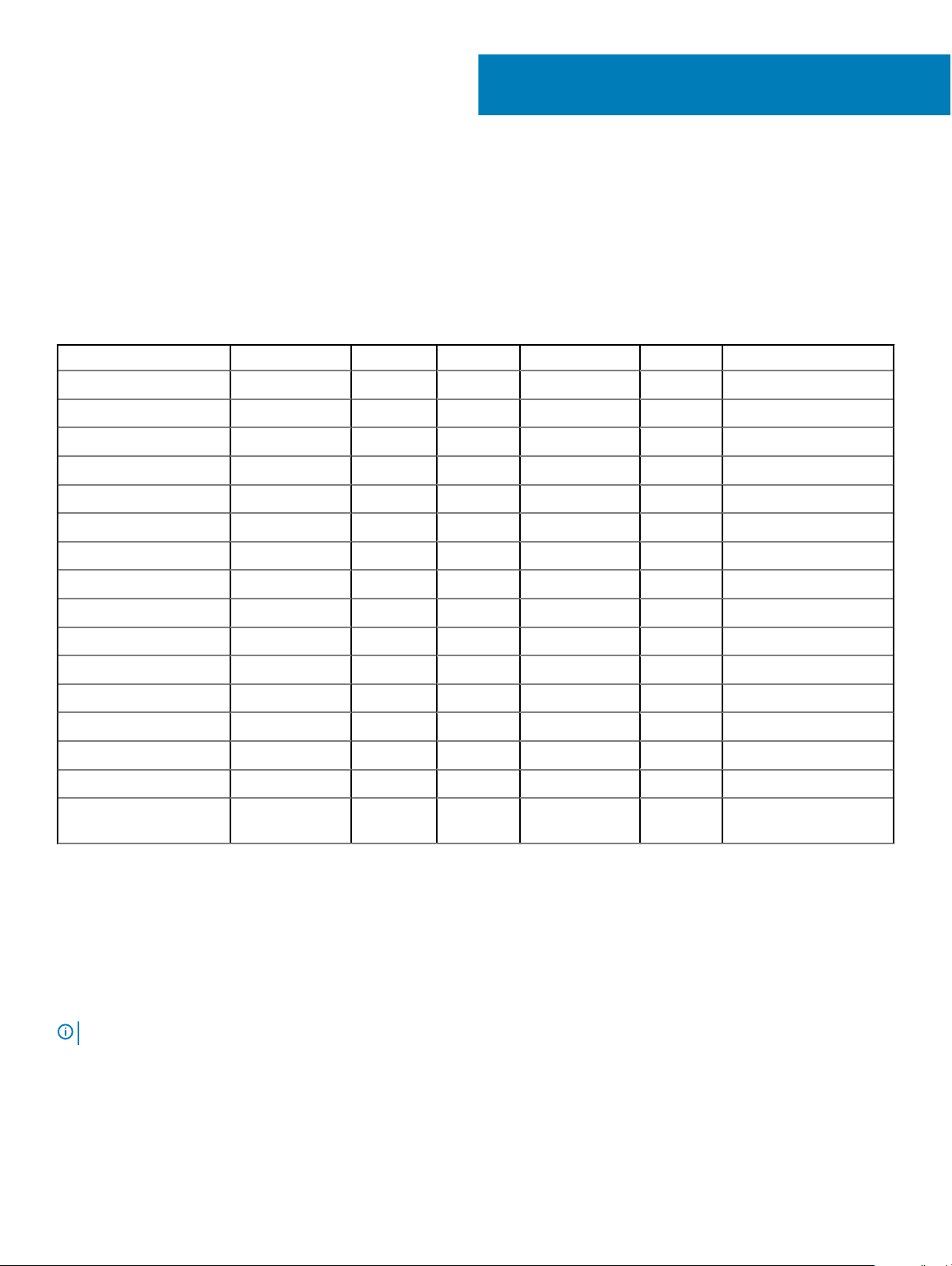
Table 1. Latitude 5289 - Screw size list
Component M2.5 x 5 M2.0 x 2 M2.0 x 3 M2.0 x 4L M 2.0 x 1.7 M 2 2.0 x 2.0
Back cover 8 (captive screw)
Battery 4
Heat sink 4
System fan 1 1
WWAN card 1
WLAN card 1
Power connector port 2
2
EDP bracket 2
Touchpad buttons 2
Fingerprint reader 1
Smart card reader cage 1
LED board 2
Keyboard support plate 13
Keyboard 6
System board 6
SSD bracket 2 (captive
screws)
Recommended tools
The procedures in this document require the following tools:
• Phillips #0 screwdriver
• Phillips #1 screwdriver
• Plastic scribe
: The #0 screw driver is for screws 0-1 and the #1 screw driver is for screws 2-4
NOTE
Micro Secure Digital (SD) Card
Removing and installing components 9

Removing the Micro Secure Digital (SD) Card
1 Follow the procedure in Before working inside your computer.
2 Press in on the Micro SD card to release it from the computer.
3 Slide the Micro SD card out of the computer.
Installing the Micro Secure Digital (SD) Card
1 Slide the Micro SD into the slot until it clicks into place.
2 Follow the procedures in After working inside your computer.
Subscriber Identity Module (SIM) Card
Removing the micro SIM card or the micro SIM card tray
CAUTION: Removing the micro SIM card when the computer is on may cause data loss or damage the card. Ensure that your
computer is turned o or the network connections are disabled.
NOTE: Micro SIM card tray is available only for systems that are shipped with WWAN card.
1 Insert a paperclip or a micro SIM card removal tool into the pinhole on the micro SIM card tray.
2 Use a scribe to pull the micro SIM card tray.
3 If a micro SIM card is available, remove the micro SIM card from the micro SIM card tray.
Base cover
Removing the base cover
1 Follow the procedure in Before working inside your computer.
2 Loosen the M2.5 x 5.0 captive screws that secure the base cover to the computer.
10
Removing and installing components
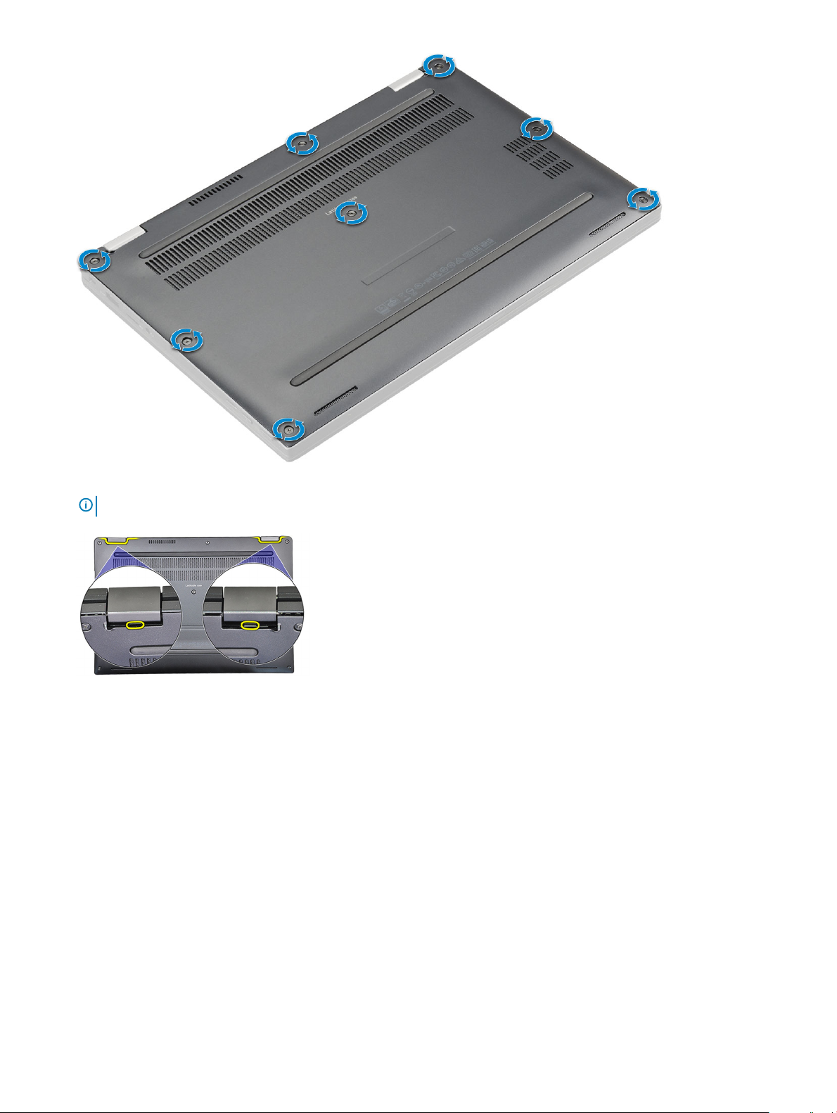
3 Use a plastic scribe to pry the base cover starting from the hinges at the top edge of the base cover and lift it from the computer.
NOTE
: The recesses are located near the hinges at the rear side of the computer.
Installing the base cover
1 Align the base cover tabs to the slots on the edges of the computer.
2 Press the edges of the cover until it clicks into place.
3 Tighten the M2.5 x 5.0 captive screws to secure the base cover to the computer.
4 Follow the procedure in After working inside your computer.
Removing and installing components
11

Battery
Lithium-ion battery precautions
CAUTION:
• Exercise caution when handling Lithium-ion batteries.
• Discharge the battery as much as possible before removing it from the system. This can be done by disconnecting the AC adapter
from the system to allow the battery to drain.
• Do not crush, drop, mutilate, or penetrate the battery with foreign objects.
• Do not expose the battery to high temperatures, or disassemble battery packs and cells.
• Do not apply pressure to the surface of the battery.
• Do not bend the battery.
• Do not use tools of any kind to pry on or against the battery.
• If a battery gets stuck in a device as a result of swelling, do not try to free it as puncturing, bending, or crushing a Lithium-ion
battery can be dangerous. In such an instance, the entire system should be replaced. Contact https://www.dell.com/support for
assistance and further instructions.
• Always purchase genuine batteries from https://www.dell.com or authorized Dell partners and re-sellers.
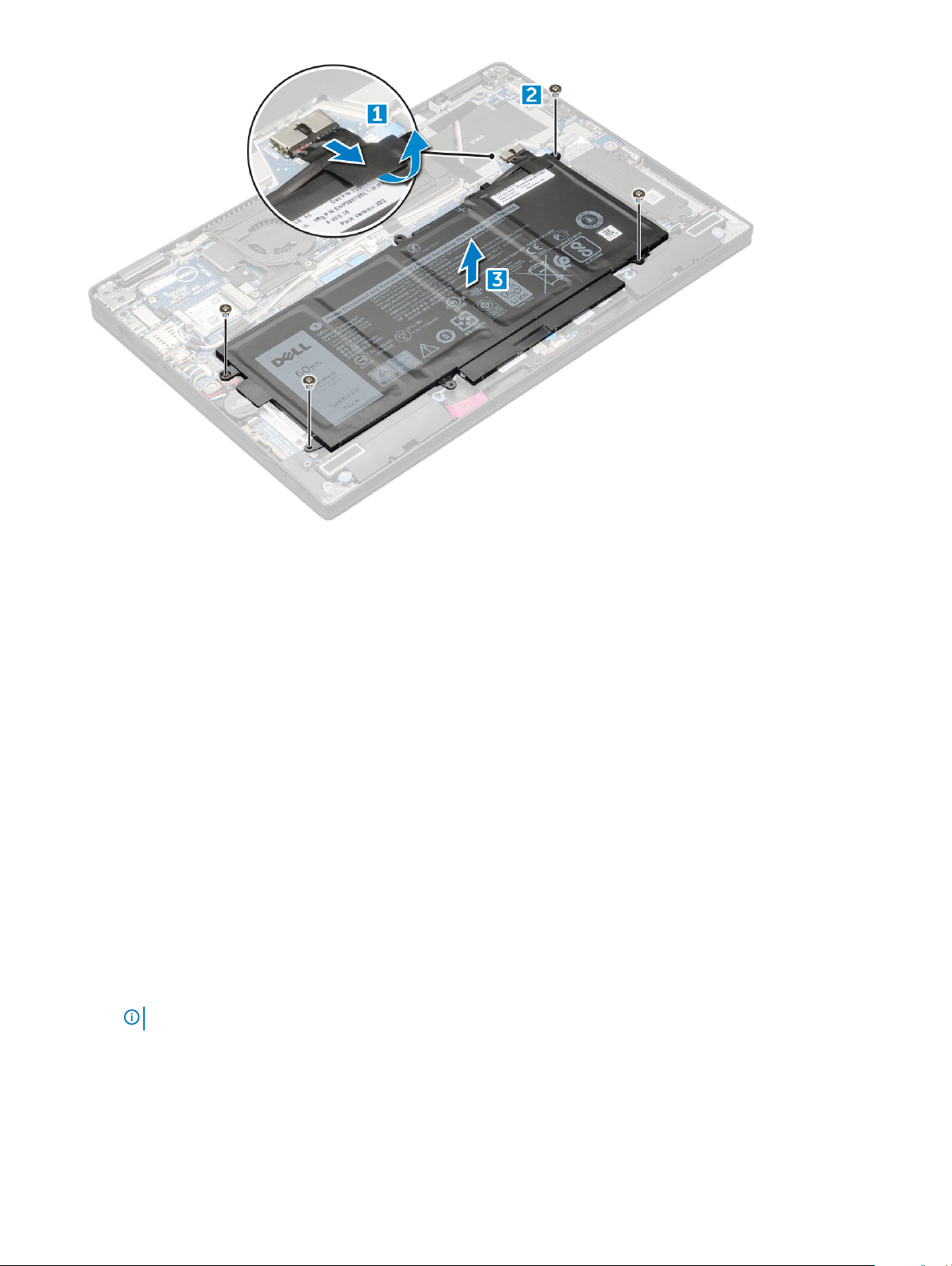
Removing the battery
1 Follow the procedure in Before working inside your computer.
2 Remove:
a MicroSD card
b base cover
3 To remove the battery:
a Lift the ribbon and disconnect the battery cable from the connector on the system board [1].
b Remove the M2.0 x 4L screws that secure the battery to the computer [2].
c Lift the battery from the computer [3].
12
Removing and installing components
Installing battery
1 Insert the battery into the slot on the computer.
2 Connect the battery cable to the connector on the system board.
3 Replace the M 2 x 4L screws to secure the battery to the computer.
4 Install the:
a base cover
b SD card
5 Follow the procedure in After working inside your computer.
PCIe Solid State Drive (SSD)
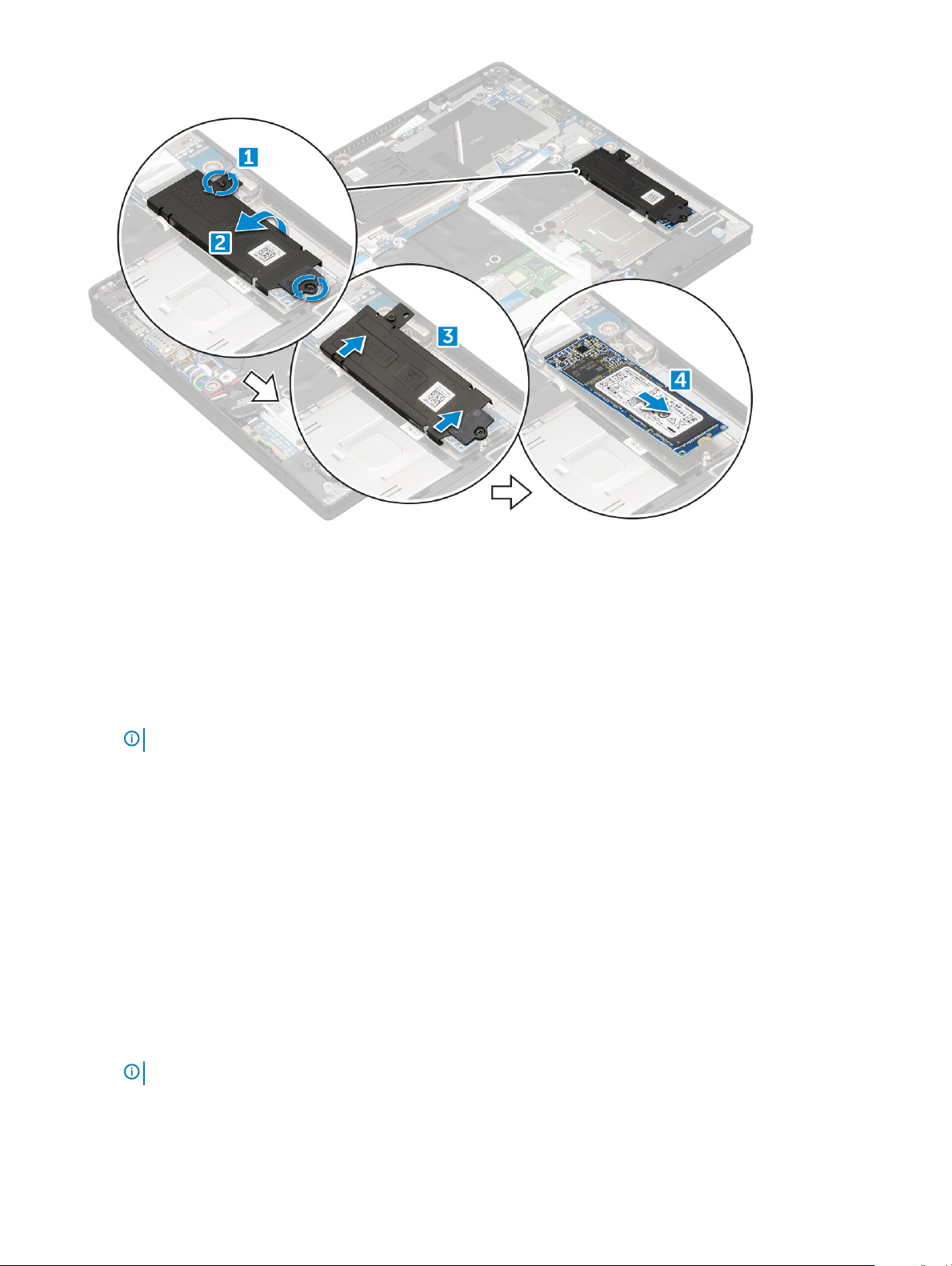
Removing the NVMe SSD card
1 Follow the procedure in Before working inside your computer.
2 Remove:
a MicroSD card
b base cover
c battery
: You need not remove the battery, instead you can disconnect the battery cable from the system board.
NOTE
3 To remove the NVMe SSD card:
a Remove the M2.0 x 3.0 screws that secure SSD thermal bracket and lift the thermal bracket [1].
b Slide the thermal bracket from the SSD card [2].
c Slide and remove the SSD card from the slot on the computer [3].
Removing and installing components
13
Installing the NVMe SSD
1 Insert the NVMe SSD card into the connector.
2 Install the thermal bracket over the SSD card.
3 Replace the M2.0 x 3.0 screws to secure the SSD thermal bracket.
4 Install the:
a battery
NOTE
: If you have not removed the battery, you must connect the battery cable to the system board.
b base cover
c MicroSD card
5 Follow the procedure in After working inside your computer.
WLAN card
Removing the WLAN card
1 Follow the procedure in Before working inside your computer.
2 Remove:
a MicroSD card
b base cover
c battery
: You need not remove battery, instead you can disconnect the battery cable from the system board.
NOTE
3 To remove the WLAN card:
a Remove the M2.0 x 3.0 screw that secures the metal bracket to the WLAN card [1].
b Lift the metal bracket [2].
Removing and installing components
14
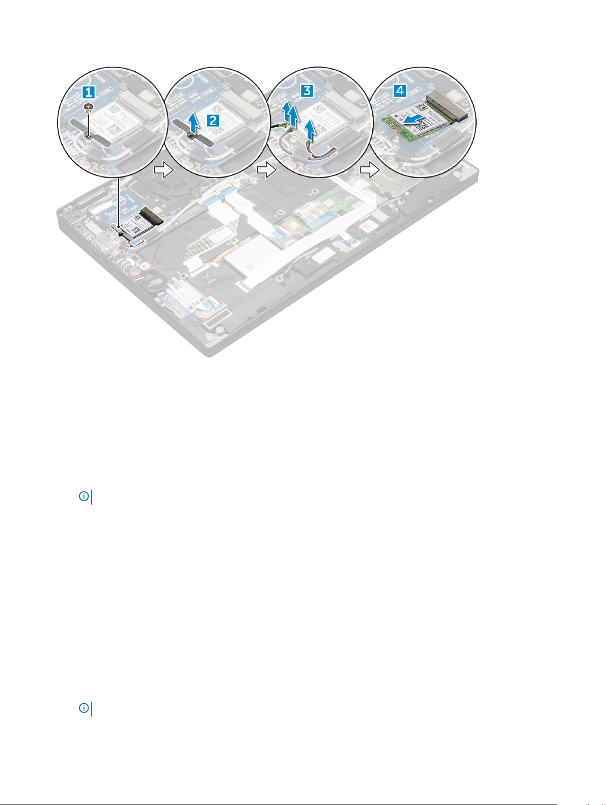
c Disconnect the WLAN cables from the connectors on the WLAN card [3].
d Remove the WLAN card from the computer [4].
Installing the WLAN card
1 Insert the WLAN card into the connector on the system board.
2 Connect the WLAN cables to the connectors on the WLAN card.
3 Place the metal bracket and replace the M2.0 x 3.0 screw to secure WLAN card to the computer.
4 Install the:
a battery
NOTE
: If you have not removed the battery then you must connect the battery cable to the system board.
b base cover
c MicroSD card
5 Follow the procedure in After working inside your computer.
WWAN card
Removing the WWAN card
1 Follow the procedure in Before working inside your computer.
2 Remove:
a MicroSD card
b base cover
c battery
: You need not remove the battery, instead you can disconnect the battery cable from the system board.
NOTE
3 To remove the WWAN card:
Removing and installing components
15

a Remove the M2.0 x 3.0 screw that secures the metal bracket to the WWAN card .
b Lift the metal bracket that secures the WWAN card .
c Disconnect the WWAN cables from the connectors on the WWAN card
d Lift the WWAN card from the computer.
Installing the WWAN card
1 Insert the WWAN card into the connector on the system board.
2 Connect the WWAN cables to the connectors on the WWAN card.
3 Place the metal bracket and replace the M2.0 x 3.0 screw to secure the WLAN card to the computer.
4 Install the:
a battery
NOTE: If you have not removed the battery then you must connect the battery cable to the system board.
b base cover
c MicroSD card
5 Follow the procedure in After working inside your computer.
NOTE: The IMEI number can also be found on the WWAN card.
Power board
Removing the power board
1 Follow the procedure in Before working inside your computer.
2 Remove:
a MicroSD card
b SIM card tray
NOTE
: SIM Card tray is available only if your computer is shipped with a WWAN card.
c base cover
d battery
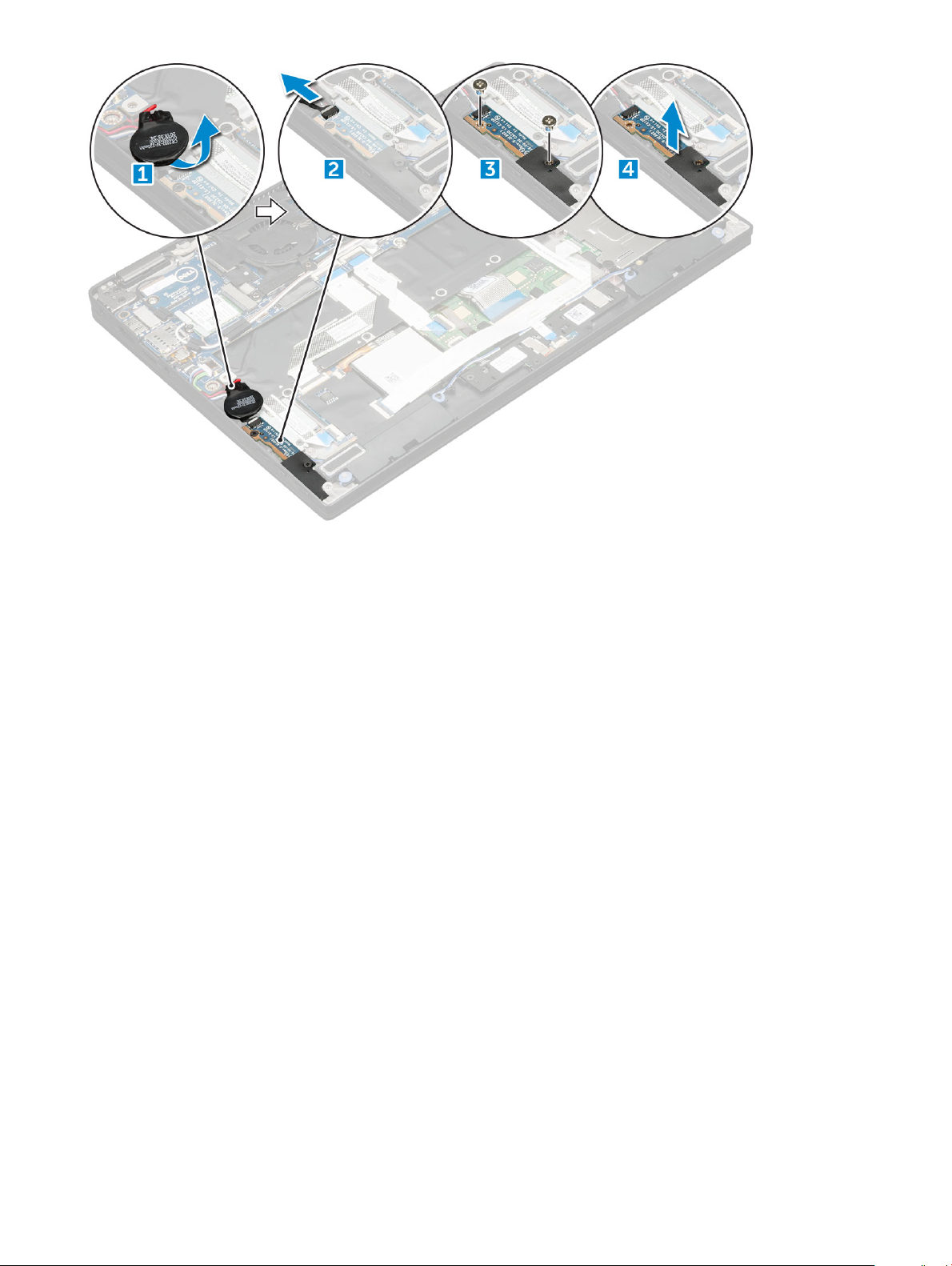
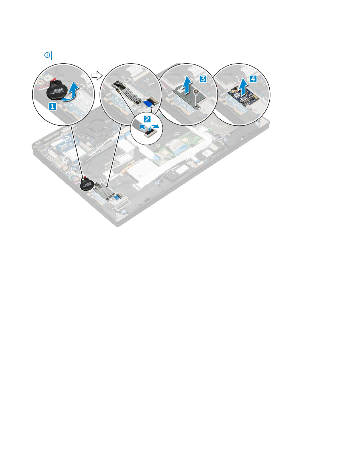
3 To remove the power board:
a Peel the coin cell battery axed to the computer [1].
b Disconnect the power cable from the system board [2].
c Remove the M2.0x3.0 screws to release the power board [3].
d Lift the power board from the computer [4].
16
Removing and installing components
Installing the power board
1 Insert the power board into the slot.
2 Replace the M2.0x3.0 screws to secure the power board to the computer.
3 Connect the power board cable to the connector on the system board.
4 Ax the coin cell battery in the slot on the computer.
5 Install the:
a battery
b base cover
c MicroSD card
6 Follow the procedure in After working inside your computer.
Speaker
Removing the speaker module
1 Follow the procedure in Before working inside your computer.
2 Remove:
a MicroSD card
b base cover
c battery
d power board
3 To disconnect the cables:
a Disconnect the and fold back the smart card cable [1].
b Disconnect and fold back the LED board cable [2].
Removing and installing components
17
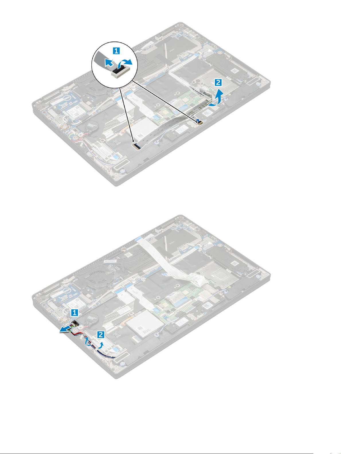
4 To release the speaker module:
a Disconnect the speaker cable from the connector on the system board [1].
b Un route the speaker cable by removing the tapes that secure the cable [2].
5 To remove the speaker module:
a Un route the speaker cable from the routing clips near the palm rest [1].
b Lift the speaker module from the computer.
Removing and installing components
18
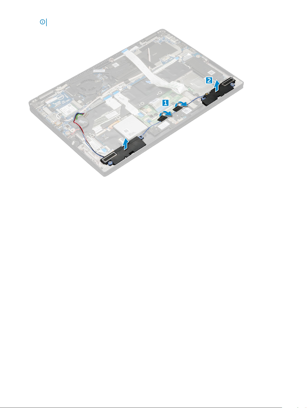
NOTE: You can use a plastic scribe to lift the speaker module from the computer.
Installing the speaker module
1 Place the speaker module into the slots on the computer.
2 Route the speaker cable through the routing channel and secure it with tapes.
3 Connect the speaker cable to the connector on the system board.
4 Connect the LED cable to the connector on the palm rest.
5 Install the:
a power board
b battery
c base cover
d Micro SD
6 Follow the procedure in After working inside your computer.
Fingerprint Board
Removing the ngerprint reader board
1 Follow the procedure in Before working inside your computer.
2 Remove:
a Micro SD
b base cover
c battery
3 To remove the ngerprint reader board:
a Lift the coin cell battery axed to the speaker cables [1].
Removing and installing components
19
b Disconnect the nger print reader cable from the ngerprint reader board and the USH board [2].
c Remove the M2 x 3 screw that secures the ngerprint reader bracket [3].
d Lift the ngerprint reader bracket from the ngerprint reader board [3].
e Lift the ngerprint reader board from the slot on the computer.
NOTE: Fingerprint reader board is axed and you may need a plastic scribe to lift the ngerprint reader board.
Installing the ngerprint reader board
1 Install the ngerprint reader board into the slot.
2 Place the ngerprint reader bracket on the board.
3 Replace the M2 x 3 screw to secure the bracket to the board.
4 Connect the ngerprint reader cable to the ngerprint reader board and the USH board.
5 Ax the coin cell battery on the speaker cable
6 Install the:
a battery
b base cover
c Micro SD
7 Follow the procedure in After working inside your computer.
LED Board
Removing the LED board
1 Follow the procedure in Before working inside your computer.
2 Remove:
Removing and installing components
20

a Micro SD
b base cover
c battery
3 To remove the LED board:
a Disconnect the LED board cable from the LED board [1].
b Remove the tape that secures the LED board to the touchpad panel [2].
c Remove the M2 x 3 screws that secure the LED board [3].
d Lift the LED board from the computer [4].
Installing the LED board
1 Install the LED board into the slot.
2 Replace the M2 x 3 screws to secure the LED board.
3 Ax the tape to secure the LED board.
4 Connect the LED board cable to the LED board.
5 Install the:
a battery
b base cover
c SD card
6 Follow the procedure in After working inside your computer.
Smart Card Cage
Removing and installing components
21
Removing the smart card cage
NOTE: Always remove the smart card from the smart card reader.
1 Follow the procedure in Before working inside your computer.
2 Remove:
a Micro SD
b base cover
c battery
d SSD card
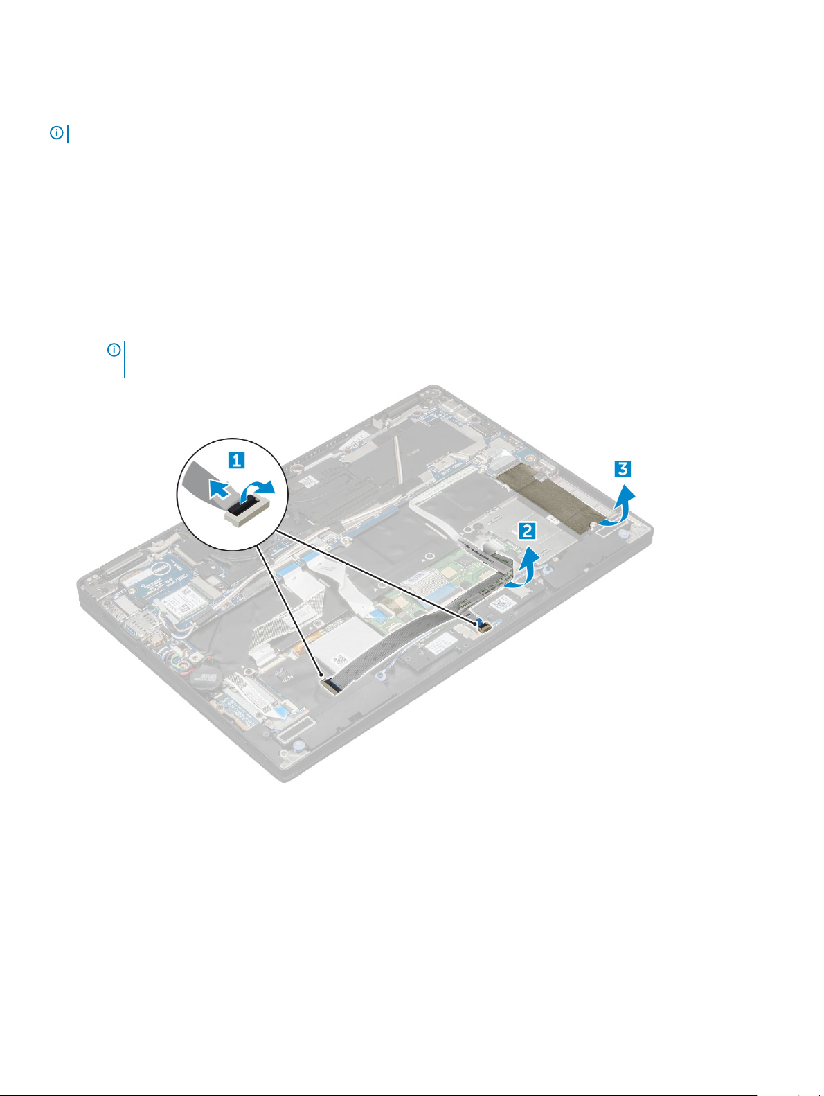
3 To disconnect the cables:
a Disconnect the smart card cable [1] and fold it away from the smart card cage.
b Disconnect the LED board cable [2] and fold it away from the smart card cage.
c Peel the SSD thermal pad from the SSD slot 3].
NOTE: You may need to apply force to peel o the SSD thermal
pad.
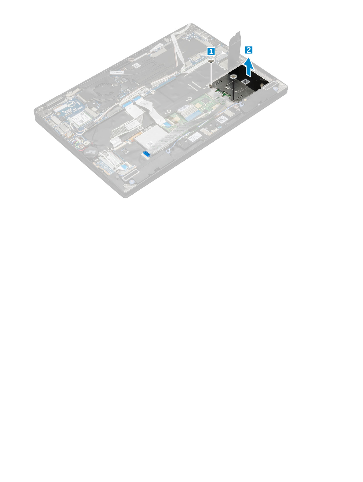
4 To remove the smart card cage:
a Remove the M2.0 x 1.7 screws that secure the smart card cage to the computer [1].
b Lift the smart card cage from the computer [2].
Removing and installing components
22
Installing the smart card cage
1 Slide the smart card cage into the slot to align with the screw holders on the computer.
2 Replace the M2.0 x 1.7 screws to secure the smart card cage to the computer.
3 Ax the thermal pad in the SSD slot.
4 Ax the LED board cable and connect it to the LED board on the computer.
5 Ax the smart card cable and connect it to the USH board on the computer .
6 Install the:
a SSD card
b battery
c base cover
d Micro SD
7 Follow the procedure in After working inside your computer.
Heat Sink
Removing heat sink assembly
1 Follow the procedure in Before working inside your computer.
2 Remove the:
a Micro SD
b base cover
c battery
3 To remove the heat sink assembly:
a Disconnect the fan cable from the system board [1].
Removing and installing components
23
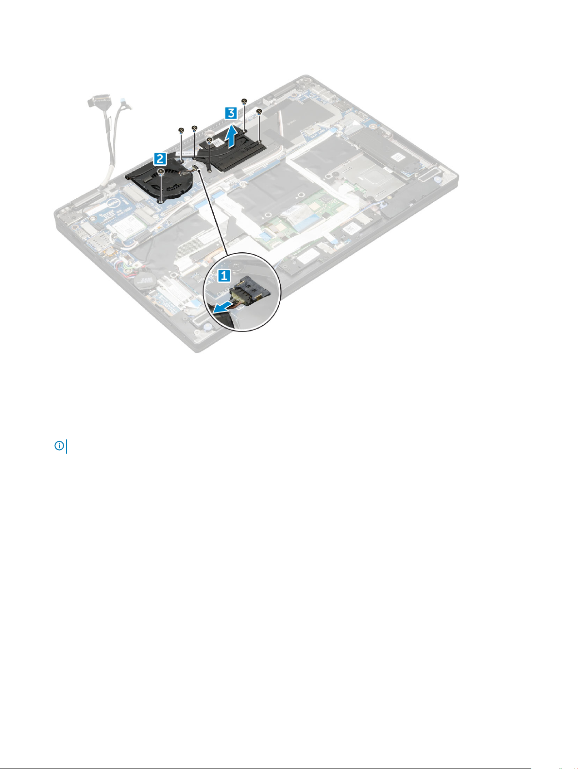
b Remove the M2.0 x 3.0 screws that secure the fan to the system board.
c Remove the M2.0 x 3.0 screws that secure the heat sink to the system board [2].
d Lift the heat sink assembly from the system board.
Installing heat sink assembly
1 Align the heat sink assembly with screw holders on the system board.
2 Replace the M2.0 x 3.0 screws to secure the heat sink to the system board.
NOTE
: Tighten the screws on the system board in the order of the callout numbers [1, 2, 3, 4] as indicated on the heat sink.
3 Replace the M2.0 x 3.0 screws to secure the fan to the system board.
4 Connect the fan cable to the connector on the system board.
5 Install the:
a battery
b base cover
6 Follow the procedure in After working inside your computer.
Display Assembly
Removing the display assembly
1 Follow the procedure in Before working inside your computer.
2 Remove the:
a Micro SD
b base cover
c battery
Removing and installing components
24
 Loading...