

Page 1

Dell PowerEdge C8220
Hardware Owner’s
Manual
Regulatory Model: B05B
Regulatory Type: B05B001
Page 2

Notes, Cautions, and Warnings
NOTE: A NOTE indicates important information that helps you make better use of
your computer.
CAUTION: A CAUTION indicates potential damage to hardware or loss of data if
instructions are not followed.
WARNING: A WARNING indicates a potential for property damage, personal
injury, or death.
____________________
Information in this publication is subject to change without notice.
© 2013 Dell Inc. All rights reserved.
Reproduction of these materials in any manner whatsoever without the written permission of Dell Inc.
is strictly forbidden.
Trademarks used in this text: Dell™, the DELL logo, and PowerEdge™ are trademarks of Dell Inc.
Intel is a registered trademark of Intel Corporation in the U.S. and other countries.
Other trademarks and trade names may be used in this publication to refer to either the entities claiming
the marks and names or their products. Dell Inc. disclaims any proprietary interest in trademarks and
trade names other than its own.
Regulatory Model B05B
Regulatory Type: B05B001
2013 - 09 P/N XXXXX Rev. A02
Page 3

Contents
1 About Your System . . . . . . . . . . . . . . . . . 11
Accessing System Features During Startup. . . . . . . 11
Front-Panel Features and Indicators . . . . . . . . . . 12
NIC Indicator Codes
Power and System Board Indicator Codes
. . . . . . . . . . . . . . . . . . . 14
. . . . . . . 16
BMC Heartbeat Indicator Codes. . . . . . . . . . . . . 17
Service Tag
POST Error Codes
. . . . . . . . . . . . . . . . . . . . . . . . 18
. . . . . . . . . . . . . . . . . . . . 19
Collecting System Event Log for
Investigation
System Event Log
Processor Error
Memory Ecc
PCIe Error
IOH Core Error
SB Error
POST Start Event
POST End Event
POST Error Code Event
BIOS Recovery Event
. . . . . . . . . . . . . . . . . . . . 19
. . . . . . . . . . . . . . . . . . . . . 27
. . . . . . . . . . . . . . . . . . . 27
. . . . . . . . . . . . . . . . . . . . 28
. . . . . . . . . . . . . . . . . . . . . . 30
. . . . . . . . . . . . . . . . . . . 31
. . . . . . . . . . . . . . . . . . . . . . . 32
. . . . . . . . . . . . . . . . . . 33
. . . . . . . . . . . . . . . . . . . 34
. . . . . . . . . . . . . . . 35
. . . . . . . . . . . . . . . . 36
ME Fail Event . . . . . . . . . . . . . . . . . . . . 37
SEL Generator ID
. . . . . . . . . . . . . . . . . . 37
Contents 3
Page 4

BMC . . . . . . . . . . . . . . . . . . . . . . . . . . . 38
Other Information You May Need
. . . . . . . . . . . . 43
2 Using the System Setup Program . . . . . 45
System Setup Menu . . . . . . . . . . . . . . . . . . . 45
System Setup Options at Boot
Using the System Setup Program Navigation
. . . . . . . . . . . . . . . . . . . . . . . . . . . . 46
Keys
General Help
. . . . . . . . . . . . . . . . . . . . . . . 47
Console Redirection . . . . . . . . . . . . . . . . . . . 47
Enabling and Configuring Console
Redirection
. . . . . . . . . . . . . . . . . . . . . 47
Serial Port Connection List
Main Menu
Advanced Menu
. . . . . . . . . . . . . . . . . . . . . . . . 52
Main Screen
System Settings
. . . . . . . . . . . . . . . . . . . . 52
. . . . . . . . . . . . . . . . . . . 53
. . . . . . . . . . . . . . . . . . . . . 55
Power Management
CPU Configuration
Memory Configuration
SATA Configuration
PCI Configuration
USB Configuration
. . . . . . . . . . . . . . 46
. . . . . . . . . . . . . 51
. . . . . . . . . . . . . . . . 56
. . . . . . . . . . . . . . . . . 62
. . . . . . . . . . . . . . . 66
. . . . . . . . . . . . . . . . . 68
. . . . . . . . . . . . . . . . . . 71
. . . . . . . . . . . . . . . . . 78
4 Contents
Security Menu
Server Menu
View System Log
. . . . . . . . . . . . . . . . . . . . . . 80
. . . . . . . . . . . . . . . . . . . . . . . 82
. . . . . . . . . . . . . . . . . . 88
Page 5

Boot Menu . . . . . . . . . . . . . . . . . . . . . . . . 89
Exit Menu
. . . . . . . . . . . . . . . . . . . . . . . . 91
Command Line Interfaces for System Setup
. . . . . . . . . . . . . . . . . . . . . . . . . . 93
Options
IPMI Command List . . . . . . . . . . . . . . . . . . . 118
Power Management Settings
. . . . . . . . . . . . . . 127
3 Installing System Components . . . . . . . 129
Safety Instructions. . . . . . . . . . . . . . . . . . . . 129
About the Illustrations . . . . . . . . . . . . . . . . . . 130
Recommended Tools
Inside the System
Sled Configuration . . . . . . . . . . . . . . . . . . . . 132
. . . . . . . . . . . . . . . . . . . . . . . . . . . . 133
Sled
Removing a Sled
Installing a Sled
. . . . . . . . . . . . . . . . . . . 130
. . . . . . . . . . . . . . . . . . . . 131
. . . . . . . . . . . . . . . . . . 133
. . . . . . . . . . . . . . . . . . . 134
Sled Blank
. . . . . . . . . . . . . . . . . . . . . . . . 134
Removing a Single-Wide Sled Blank
Installing a Single-Wide Sled Blank
Removing a Double-Wide Sled Blank
Installing a Double-Wide Sled Blank
MicroSD Card
. . . . . . . . . . . . . . . . . . . . . . 137
Removing a MicroSD Card
Installing a MicroSD Card
. . . . . . . . 134
. . . . . . . . 135
. . . . . . . 136
. . . . . . . . 136
. . . . . . . . . . . . . 137
. . . . . . . . . . . . . 138
Contents 5
Page 6

Sled Covers. . . . . . . . . . . . . . . . . . . . . . . 138
Removing the Front Cover
Installing the Front Cover
. . . . . . . . . . . . 138
. . . . . . . . . . . . . 139
Removing the Back Cover . . . . . . . . . . . . 140
Installing the Back Cover
. . . . . . . . . . . . . 141
Cooling Shroud
. . . . . . . . . . . . . . . . . . . . . 141
Removing the Cooling Shroud
Installing the Cooling Shroud
Heat Sink
Heat Sink Blank
. . . . . . . . . . . . . . . . . . . . . . . . 143
Removing a Heat Sink
Installing a Heat Sink
. . . . . . . . . . . . . . . . . . . . 145
. . . . . . . . . . . . . . . 143
. . . . . . . . . . . . . . . 144
Removing a Heat Sink Blank
Installing a Heat Sink Blank
Processors
System Memory
. . . . . . . . . . . . . . . . . . . . . . . 147
Removing a Processor
Installing a Processor
. . . . . . . . . . . . . . . . . . . . 150
. . . . . . . . . . . . . . 147
. . . . . . . . . . . . . . . 148
Memory Module Installation Guidelines
Supported DIMM Configuration
Removing Memory Modules
Installing Memory Modules
Expansion Card
. . . . . . . . . . . . . . . . . . . . . 155
Removing the Expansion Card
Installing the Expansion Card
Removing the RAID Controller Card
Installing the RAID Controller Card
. . . . . . . . . . 141
. . . . . . . . . . . 142
. . . . . . . . . . . 145
. . . . . . . . . . . . 146
. . . . . 150
. . . . . . . . . 151
. . . . . . . . . . . 153
. . . . . . . . . . . . 154
. . . . . . . . . . 155
. . . . . . . . . . . 156
. . . . . . . 157
. . . . . . . . 158
6 Contents
Page 7

RAID Battery . . . . . . . . . . . . . . . . . . . . . . . 159
Removing the RAID Battery
Installing the RAID Battery
. . . . . . . . . . . . 159
. . . . . . . . . . . . . 161
Removing the RAID Battery Holder. . . . . . . . . 162
Installing the RAID Battery Holder
. . . . . . . . . 164
Expansion Card Riser
Removing the Expansion Card Riser
Installing the Expansion Card Riser
Mezzanine Cards
Removing the Infiniband Mezzanine Card
Installing the Infiniband Mezzanine Card
Removing the 10 GbE Mezzanine Card
. . . . . . . . . . . . . . . . . . 164
. . . . . . . . 164
. . . . . . . . 165
. . . . . . . . . . . . . . . . . . . . . 166
. . . . . 166
. . . . . 169
. . . . . . . 170
Installing the 10 GbE Mezzanine Card . . . . . . . 172
MicroSD Card Reader . . . . . . . . . . . . . . . . . . 173
Removing the MicroSD Card Reader
. . . . . . . . 173
Installing the MicroSD Card Reader . . . . . . . . 175
Removing the MicroSD Card Reader
Support Bracket
. . . . . . . . . . . . . . . . . . 176
Installing the MicroSD Card Reader
Support Bracket . . . . . . . . . . . . . . . . . . 177
Internal Hard-Drives
Removing a Hard-Drive Carrier
Installing a Hard-Drive Carrier
. . . . . . . . . . . . . . . . . . . 178
. . . . . . . . . . . 178
. . . . . . . . . . . 179
Removing a Hard-Drive From the
Hard-Drive Carrier . . . . . . . . . . . . . . . . . 179
Installing a Hard-Drive Into a Hard-Drive
Carrier
. . . . . . . . . . . . . . . . . . . . . . . . 180
Removing the Hard-Drive Tray . . . . . . . . . . . 181
Installing the Hard-Drive Tray
. . . . . . . . . . . 182
Contents 7
Page 8

Interposer Extender . . . . . . . . . . . . . . . . . . 182
Removing the Interposer Extender
Installing the Interposer Extender
. . . . . . . . 182
. . . . . . . . 184
Node Power Distribution Board
Removing the Node Power Distribution Board
Installing the Node Power Distribution Board
System Battery
. . . . . . . . . . . . . . . . . . . . . 187
Removing the System Battery
Installing the System Battery
System Board
. . . . . . . . . . . . . . . . . . . . . . 189
Removing the System Board
Installing the System Board
. . . . . . . . . . . . 184
. . 184
. . 186
. . . . . . . . . . 187
. . . . . . . . . . . 188
. . . . . . . . . . . 189
. . . . . . . . . . . 193
4 Troubleshooting. . . . . . . . . . . . . . . . . . . 197
Safety First—For You and Your System . . . . . . . . 197
Installation Problems
Troubleshooting System Startup Failure. . . . . . . . 198
Troubleshooting External Connections
Troubleshooting the Video Subsystem
. . . . . . . . . . . . . . . . . 197
. . . . . . . . 198
. . . . . . . . . 198
8 Contents
Troubleshooting a USB Device
Troubleshooting a Serial I/O Device
Troubleshooting a NIC
. . . . . . . . . . . . 198
. . . . . . . . . . 199
. . . . . . . . . . . . . . . . . 200
Troubleshooting a Wet Enclosure . . . . . . . . . . . 201
Troubleshooting a Damaged Enclosure
. . . . . . . . 202
Page 9

Troubleshooting the Power Sled . . . . . . . . . . . . 203
Troubleshooting System Memory
. . . . . . . . . . . . 203
Troubleshooting a Hard-Drive . . . . . . . . . . . . . . 205
Troubleshooting a Storage Controller
Troubleshooting Expansion Cards
. . . . . . . . . . 206
. . . . . . . . . . . . 207
Troubleshooting Processors. . . . . . . . . . . . . . . 208
Identifying System Board Model Number
Troubleshooting the System Board
. . . . . . . . 209
. . . . . . . . . . . 210
Troubleshooting the System Battery. . . . . . . . . . . 210
IRQ Assignment Conflicts
. . . . . . . . . . . . . . . . 211
5 Jumpers and Connectors . . . . . . . . . . . 213
System Board Types . . . . . . . . . . . . . . . . . . . 213
System Board Jumper Settings . . . . . . . . . . . . . 214
System Board V1.0 Jumper Settings
System Board V1.1 Jumper Settings
System Board V1.2 Jumper Settings
. . . . . . . . 214
. . . . . . . . 215
. . . . . . . . 217
System Board Connectors
. . . . . . . . . . . . . . . . 219
System Board V1.0 Connectors
System Board V1.1 Connectors
System Board V1.2 Connectors
Interposer Extender Connectors
Interpose Extender Types
. . . . . . . . . . . . . 224
MicroSD Card Reader Connectors
. . . . . . . . . . 219
. . . . . . . . . . 220
. . . . . . . . . . 222
. . . . . . . . . . . . . 224
. . . . . . . . . . . 226
Contents 9
Page 10

Node Power Distribution Board Connectors . . . . . 227
6 Getting Help . . . . . . . . . . . . . . . . . . . . . . 229
Contacting Dell . . . . . . . . . . . . . . . . . . 229
Index . . . . . . . . . . . . . . . . . . . . . . . . . . . . . . 231
10 Contents
Page 11

1
About Your System
Accessing System Features During Startup
The following keystrokes provide access to system features during startup.
The SAS/SATA card or PXE hotkey support are available only in the BIOS
boot mode. Hotkey function is not available in the Unified Extensible
Firmware Interface (UEFI) boot mode.
Keystroke Description
<F2> Enters the System Setup program. See "System Setup Menu" on
page 45.
<F11> Enters the BIOS Boot Manager or the Unified Extensible
Firmware Interface (UEFI) Boot Manager, depending on the
system's boot configuration.
<F12> Starts Preboot eXecution Environment (PXE) boot.
<Ctrl><C> Enters the LSI 2008 SAS Mezzanine Card Configuration Utility.
For more information, see the SAS adapter documentation.
<Ctrl><H> Enters the LSI 2008 SAS Mezzanine Card Configuration Utility.
For more information, see the documentation for your SAS RAID
card.
<Ctrl><S> Enters the utility to configure onboard NIC settings for PXE boot.
For more information, see the documentation for your integrated
NIC.
<Ctrl><I> Enters the onboard SAS and SATA controller’s configuration
utility.
NOTE: Throughout this manual, the PowerEdge C8000 server enclosure is referred
to as simply the "server enclosure" or the "chassis".
About Your System 11
Page 12
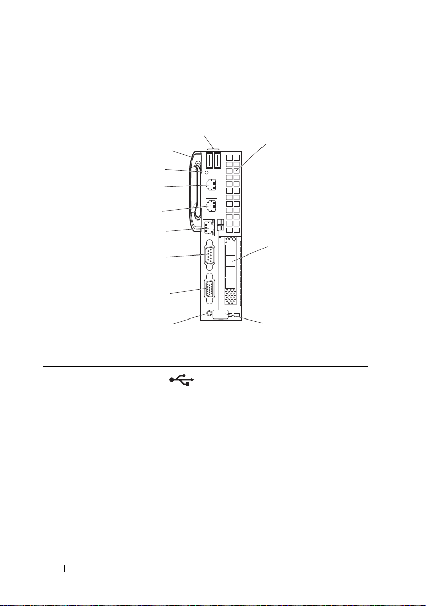
Front-Panel Features and Indicators
1
2
3
4
5
6
7
8
9
10
11
12
Figure 1-1. Front-Panel Features and Indicators
Item Indicator, Button, or
Connector
1 USB connectors Connects USB devices to the system. The
2 Mezzanine card
expansion slot
3 Low profile PCIe
4 Release latch Press to release the sled from the
12 About Your System
expansion slot
Icon Description
ports are USB 2.0 compliant.
Installs an I/O module mezzanine card.
Installs a low profile PCI Express x16 card.
enclosure.
Page 13

Item Indicator, Button, or
Connector
5Power-on indicator/
power button
Icon Description
The power-on indicator lights when the
sled power is on. The power-on indicator
lights amber when the system critical
event occurs.
NOTE: The power-on indicator lights amber
according to critical system error log (SEL)
assertion. If the SEL is full or a deassertion
event occurred while sensor monitoring is
paused (e.g. fan monitoring is paused during
system power off), the power-on indicator
turns amber. To turn off an amber LED and
reset the power-on indicator to normal
condition (solid green), either perform a
BMC cold reset or reseat the sled in the
server enclosure.
The power button turns the compute
sled on.
NOTES:
• When powering on the sled, the video
monitor can take from several seconds to
over 2 minutes to display an image,
depending on the amount of memory
installed in the system.
• On ACPI-compliant operating systems,
turning off the sled using the power
button causes the sled to perform a
graceful shutdown before power to the
sled is turned off.
• To force an ungraceful shutdown, press
and hold the power button for five
seconds.
6 VGA connector Connects a VGA display to the system.
7 Serial connector Connects a serial device to the system.
About Your System 13
Page 14
Item Indicator, Button, or
2
1
Connector
8 BMC management
port
9 Ethernet connector 2 Embedded 10/100/1000 Mbit NIC
10 Ethernet connector 1 Embedded 10/100/1000 Mbit NIC
11 Sled identification
indicator
12 Handle Hold to pull the sled from the enclosure.
Icon Description
Dedicated management port.
connector.
connector.
Lights blue to identify a particular system
and system board.
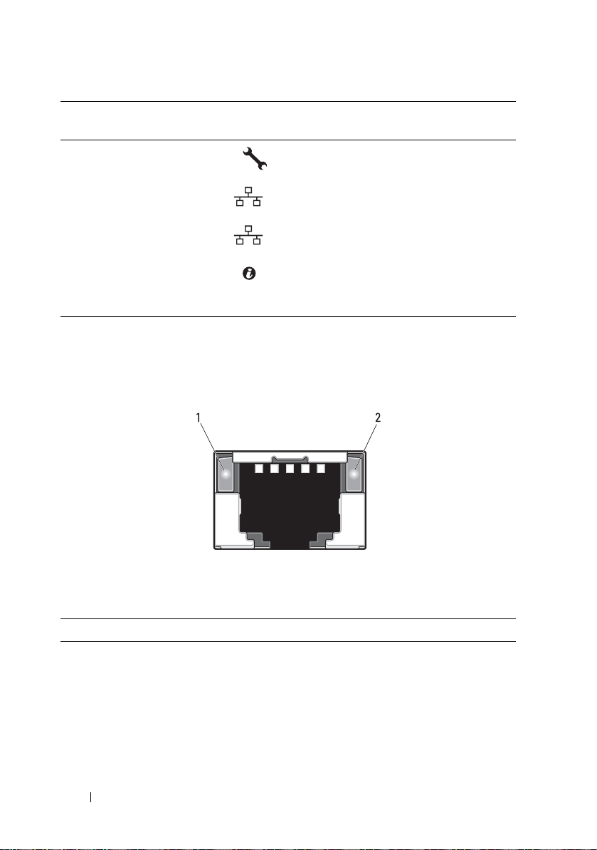
NIC Indicator Codes
Figure 1-2. NIC Indicators
1 link indicator 2 activity indicator
Indicator Status Indicator Code
Link indicator Solid amber Linking at 100 Mbps port speed
Solid green Linking at 1 Gbps port speed (maximum)
14 About Your System
Page 15
Indicator Status Indicator Code
Blinking green Linking at 1 Gbps port speed
Network activity is present
•Pre OS POST
•OS without driver
•OS with driver
Blinks at speed relative to packet density
Off Linking at 10 Mbps port speed
Activity
indicator
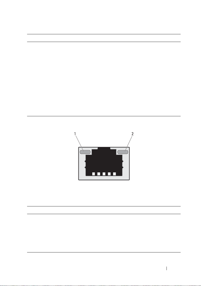
Figure 1-3. NIC Indicators (BMC management port)
Solid green No activity
Blinking green Transmit or receive activity
Off Idle
1 link indicator 2 activity indicator
Indicator Status Indicator Code
Link indicator Blinking amber Linking at 10 Mbps port speed
Blinking green Linking at 100 Mbps port speed (maximum)
Activity
indicator
Solid green No activity
Blinking green Transmit or receive activity
Off Idle
About Your System 15
Page 16

Power and System Board Indicator Codes
The indicators on the front of the sled display status codes during system
startup. For location of the indicators on the front panel, see Figure 1-1.
Table 1-1. Power and System Board Indicator Codes
Indicator Color Status Indicator Code
Power-on
indicator
System
identification
indicator
Green Solid
Amber Off
Green Solid BMC critical condition event in power off
Amber Blinking
Green Off BMC critical condition event in power on
Amber Blinking
Blue Solid The IPMI via Chassis Identify Command On
Blue Blinking Only the IPMI via Chassis Identify Command
Off The IPMI via Chassis Identify Command Off
Sled power is on (S0)
mode (S4/S5)
mode (S0)
or ID Button Press ID On is generated
Blink On is generated
or ID Button Press ID Off is generated
16 About Your System
Page 17
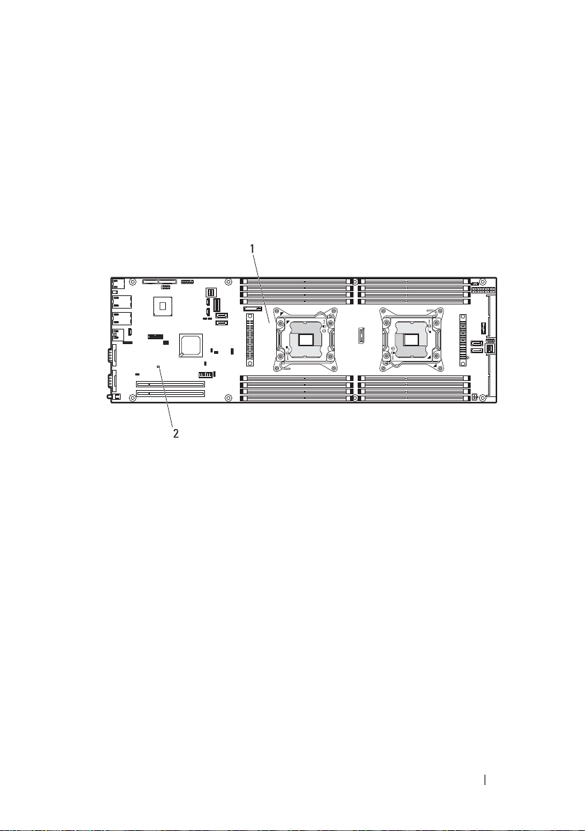
BMC Heartbeat Indicator Codes
The system board includes a BMC heartbeat indicator (LED17) for
debugging the Baseboard Management Controller (BMC). The BMC
heartbeat indicator lights green when power is supplied to the sled and blinks
green when the BMC firmware is ready.
Figure 1-4. BMC Heartbeat Indicator
1 system board 2 BMC heartbeat indicator
About Your System 17
Page 18
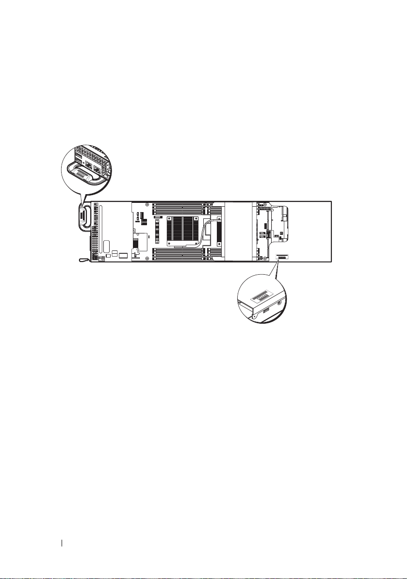
Service Tag
The following illustration provides location of the Service Tag number on the
C8220 single-wide compute sled.
Figure 1-5. Service Tag Location for C8220 Single-Wide Compute Sled
18 About Your System
Page 19

POST Error Codes
Collecting System Event Log for Investigation
Whenever possible, the system BIOS will output the current boot progress
codes on the video screen. Progress codes are 32-bit quantities plus optional
data. The 32-bit numbers include class, subclass, and operation information.
The class and subclass fields point to the type of hardware that is being
initialized. The operation field represents the specific initialization activity.
Based on the data bit availability to display progress codes, a progress code
can be customized to fit the data width. The higher the data bit, the higher
the granularity of information that can be sent on the progress port. The
progress codes may be reported by the system BIOS or option ROMs.
The Response section in the following table may be divided into 3 types:
• Warning or Not an error – The message is displayed on the screen. An error
record is logged to the SEL. The system will continue booting with a
degraded state. The user may want to replace the erroneous unit.
• Pause – The message is displayed on the screen, an error is logged to the
SEL, and user input is required to continue. The user can take immediate
corrective action or choose to continue booting.
• Halt – The message is displayed on the screen, an error is logged to the
SEL, and the system cannot boot unless the error is resolved. The user
needs to replace the faulty part and restart the system.
Error
Code
0010h Local Console
0011h Local Console
Error Message Response Error Cause Corrective Actions
Resource
Conflict
Controller Error
Pau s e Vid e o device
initialization
failed
Pau s e Vid e o device
initialization
failed
See "Troubleshooting the
Video Subsystem" on
page 198.
If the problem persists, see
"Getting Help" on page 229.
See "Troubleshooting the
Video Subsystem" on
page 198.
If the problem persists, see
"Getting Help" on page 229.
About Your System 19
Page 20

Error
Code
0012h Local Console
0013h ISA IO
0014h ISA IO Resource
0015h ISA IO
0016h ISA Floppy
0017h ISA Floppy
0018h ISA Floppy
Error Message Response Error Cause Corrective Actions
Output Error
Controller Error
Conflict
Controller Error
Controller Error
Input Error
Output Error
Pau s e Vid e o device
initialization
failed
Pau s e ISA de v ice
initialization
failed
Pau s e ISA de v ice
initialization
failed
Pau s e ISA de v ice
initialization
failed
Pause Floppy device
initialization
failed
Pause Floppy device
initialization
failed
Pause Floppy device
initialization
failed
See "Troubleshooting the
Video Subsystem" on
page 198.
If the problem persists, see
"Getting Help" on page 229.
See "Troubleshooting
Expansion Cards" on
page 207.
If the problem persists, see
"Getting Help" on page 229.
See "Troubleshooting
Expansion Cards" on
page 207.
If the problem persists, see
"Getting Help" on page 229.
See "Troubleshooting
Expansion Cards" on
page 207.
If the problem persists, see
"Getting Help" on page 229.
See "Troubleshooting a USB
Device" on page 198.
If the problem persists, see
"Getting Help" on page 229.
See "Troubleshooting a USB
Device" on page 198.
If the problem persists, see
"Getting Help" on page 229.
See "Troubleshooting a USB
Device" on page 198.
If the problem persists, see
"Getting Help" on page 229.
20 About Your System
Page 21

Error
Code
0019h USB Read Error Pause USB port
001Ah USB Write Error Pause USB port
001Bh USB Interface
001Ch Mouse Interface
001Eh Keyboard Not
001Fh Keyboard
Error Message Response Error Cause Corrective Actions
initialization
failed
initialization
failed
Pau s e USB po r t
Error
Pau s e Mouse d evice
Error
Pause No keyboard
Detected
Pau se Key boar d
Controller Error
initialization
failed
initialization
failed
detected
controller
initialization
failed
See "Troubleshooting a USB
Device" on page 198.
If the problem persists, see
"Getting Help" on page 229.
See "Troubleshooting a USB
Device" on page 198.
If the problem persists, see
"Getting Help" on page 229.
See "Troubleshooting a USB
Device" on page 198.
If the problem persists, see
"Getting Help" on page 229.
To enable USB device, see
"USB Configuration" on
page 78.
See "Troubleshooting a USB
Device" on page 198.
If the problem persists, see
"Getting Help" on page 229.
To enable USB device, see
"USB Configuration" on
page 78.
See "Troubleshooting a USB
Device" on page 198.
If the problem persists, see
"Getting Help" on page 229.
See "Troubleshooting a USB
Device" on page 198.
If the problem persists, see
"Getting Help" on page 229.
About Your System 21
Page 22

Error
Code
0020h Keyboard Stuck
0021h Keyboard
0023h Memory
0024h Memory
0025h Memory Non-
0026h MP Service Self
0027h PCI IO
Error Message Response Error Cause Corrective Actions
Key Error
Locked Error
Correctable
Error
Uncorrectable
Error
Specific Error
Tes t Er r or
Controller Error
Pau s e Key board key
stuck
Pau se Ke ybo ard
locked
Pau se Me mory
correctable
error detected
Pau se Me mory
uncorrectable
error detected
Pause Memory non-
specific error
detected
Pause MP service self
test error
detected
Pau s e PCI de vice
initialization
failed
Disconnect and reconnect the
keyboard to the compute sled.
If the problem persists, see
"Getting Help" on page 229.
Disconnect and reconnect the
keyboard to the compute sled.
If the problem persists, see
"Getting Help" on page 229.
Remove AC power to the
system for 10 seconds and
restart the system.
See "Troubleshooting System
Memory" on page 203.
If the problem persists, see
"Getting Help" on page 229.
See "Troubleshooting System
Memory" on page 203.
If the problem persists, see
"Getting Help" on page 229.
See "Troubleshooting System
Memory" on page 203.
If the problem persists, see
"Getting Help" on page 229.
See "Troubleshooting
Processors" on page 208.
If the problem persists, see
"Getting Help" on page 229.
See "Troubleshooting
Expansion Cards" on
page 207.
If the problem persists, see
"Getting Help" on page 229.
22 About Your System
Page 23

Error
Code
0028h PCI IO Read
0029h PCI IO Write
002Ah Serial Port Not
002Bh Serial Port
002Ch Serial Port Input
002Dh Serial Port
002Eh Microcode
Error Message Response Error Cause Corrective Actions
Error
Error
Detected
Controller Error
Error
Output Error
Update Error
Pau s e PCI de v ice
initialization
failed
Pau s e PCI de v ice
initialization
failed
Pau s e Seria l device
initialization
failed
Pau s e Seria l device
initialization
failed
Pau s e Seria l device
initialization
failed
Pau s e Seria l device
initialization
failed
Pause Processor
microcode
update error
See "Troubleshooting
Expansion Cards" on
page 207.
If the problem persists, see
"Getting Help" on page 229.
See "Troubleshooting
Expansion Cards" on
page 207.
If the problem persists, see
"Getting Help" on page 229.
See "Troubleshooting a Serial
I/O Device" on page 199.
If the problem persists, see
"Getting Help" on page 229.
See "Troubleshooting a Serial
I/O Device" on page 199.
If the problem persists, see
"Getting Help" on page 229.
See "Troubleshooting a Serial
I/O Device" on page 199.
If the problem persists, see
"Getting Help" on page 229.
See "Troubleshooting a Serial
I/O Device" on page 199.
If the problem persists, see
"Getting Help" on page 229.
Check microcode. A BIOS
update is required.
If the problem persists, see
"Getting Help" on page 229.
About Your System 23
Page 24

Error
Code
002Fh No Microcode
8012h SATA 0 Device
8013h SATA 1 Device
8014h SATA 2 Device
8015h SATA 3 Device
Error Message Response Error Cause Corrective Actions
Be Updated
Not Found
Not Found
Not Found
Not Found
Pause Processor
microcode load
failed
Pause SATA 0 device
not found
Pause SATA 1 device
not found
Pause SATA 2 device
not found
Pause SATA 3 device
not found
Ensure that your processors
match and conform to the
type described in the
processor technical
specifications outlined in
your system’s Getting Started
Guide.
Check if the SATA port 0 is
enabled. See "SATA
Configuration" on page 68.
Install a SATA device to SATA
port 0.
If the problem persists, see
"Getting Help" on page 229.
Check if the SATA port1 is
enabled. See "SATA
Configuration" on page 68.
Install a SATA device to SATA
port 1.
If the problem persists, see
"Getting Help" on page 229.
Check if the SATA port 2 is
enabled. See "SATA
Configuration" on page 68.
Install a SATA device to SATA
port 2.
If the problem persists, see
"Getting Help" on page 229.
Check if the SATA port 3 is
enabled. See "SATA
Configuration" on page 68.
Install a SATA device to SATA
port 3.
If the problem persists, see
"Getting Help" on page 229.
24 About Your System
Page 25

Error
Code
8016h SATA 4 Device
8017h SATA 5 Device
8018h Sparing Mode is
8019h Mirror Mode is
8020h Supervisor and
Error Message Response Error Cause Corrective Actions
Not Found
Not Found
not be
Configured!!,
Please check
Memory
Configuration!!
not be
Configured!!,
Please check
Memory
Configuration!!
User Passwords
have been
cleared
Pause SATA 4 device
not found
Pause SATA 5 device
not found
Pau se Mem ory
Sparing Mode
Failed
Pause Memory Mirror
Mode Failed
Pause Supervisor and
User Passwords
have been
cleared
Check if the SATA port 4 is
enabled. See "SATA
Configuration" on page 68.
Install a SATA device to SATA
port 4.
If the problem persists, see
"Getting Help" on page 229.
Check if the SATA port 5 is
enabled. See "SATA
Configuration" on page 68.
Install a SATA device to SATA
port 5.
If the problem persists, see
"Getting Help" on page 229.
Check if the memory
configuration is set to Sparing
mode. See "Memory
Configuration" on page 66.
If the problem persists, see
"Getting Help" on page 229.
Check if the memory
configuration is set to Sparing
mode. See "Memory
Configuration" on page 66.
If the problem persists, see
"Getting Help" on page 229.
Reset password. See "System
Board Jumper Settings" on
page 214 for more
information.
If the problem persists, see
"Getting Help" on page 229.
About Your System 25
Page 26

Error
Code
8021h CMOS Battery
8100h Memory device
Error Message Response Error Cause Corrective Actions
Error
disabled by
BIOS
Pause No CMOS
battery
Pau se Me mory
Device Error
See "Troubleshooting the
System Battery" on page 210.
See "Troubleshooting System
Memory" on page 203.
If the problem persists, see
"Getting Help" on page 229.
26 About Your System
Page 27

System Event Log
Processor Error
Message: “Processor Sensor, IERR error, Processor 1”
Table 1-2. Processor Error
Byte Field Value Description
1 NetFunLun 10h
2 Platform Event Command 02h
3 Generator ID 01h Generated by BIOS
4 Event Message Format
Ve rs io n
5 Sensor Type 07h Processor
6 Sensor Number 04h Processor Sensor Number
7 Event Direction Event Type 6Fh Bit 7: 0 = Assert Event Bit 6: 0 =
8 Event Data1 AXh 00h: IERR 01h: Thermal Trip
9 Event Data2 XXh 00h: Processor1
10 Event Data3 FFh FFh: Not Present
04h Event Message Format Revision.
04h for this specification
(depends on platform)
Event Type Code
02h: FRB1/BIST Failure
03h: FRB2/Hang in POST Failure
04h: FBR3/Processor
Startup/Initialization Failure
0Ah: Processor Automatically
Throttled
01h: Processor2
02h: Processor3
04h: Processor4
About Your System 27
Page 28

Memory Ecc
Message: “Memory Sensor, Correctable ECC error, SBE warning threshold,
CPU1 DIMM_A1”
Table 1-3. Memory ECC
Byte Field Value Description
1 NetFunLun 10h
2 Platform Event Command 02h
3 Generator ID 01h Generated by BIOS
4 Event Message Format
Ve rs io n
5 Sensor Type 0Ch Memory
6 Sensor Number 60h Memory Sensor Number (depend
7 Event Direction Event Type 6Fh Bit 7: 0 = Assert Event
8 Event Data1 AXh 00h: Correctable ECC Error
04h Event Message Format Revision.
04h for this specification
on platform)
Bit 6: 0 = Event Type Code
01h: Uncorrectable ECC Error
03h: Memory Scrub Failed
04h: Memory Device Disabled
08h: Spare
28 About Your System
Page 29

Table 1-3. Memory ECC
Byte Field Value Description
9 Event Data2 XXh Bit 7:4
0x00: SBE warning threshold
0x01: SBE critical threshold
0x0F: Unspecified
Bit 3:0
0x00: CPU1 DIMM A1-8 slots
(1~8)
0x01: CPU2 DIMM B1-8 slots
(9~16)
0x02: CPU3 DIMM C1-8 slots
(17~24)
0x03: CPU4 DIMM D1-8 slots
(25~32) And so on…
10 Event Data3 XXh DIMM bit-map location of bits
Bit 0=1: DIMM1 error event
Bit 1=1: DIMM2 error event …
Bit7=1: DIMM8 error event
About Your System 29
Page 30

PCIe Error
Message: “Critical Interrupt Sensor, PCI PERR, Device#, Function#,
Bus#”
Table 1-4. PCIe Error
Byte Field Value Description
1 NetFunLun 10h
2 Platform Event Command 02h
3 Generator ID 01h Generated by BIOS
4 Event Message Format
Ve rs io n
5 Sensor Type 13h Critical Interrupt
6 Sensor Number 73h PCI Sensor ID (depend on
7 Event Direction Event Type 6Fh Bit 7: 0 = Assert Event
8 Event Data1 AXh 04h: PCI PERR
9 Event Data2 XXh Bit 7:3Device Number
10 Event Data3 XXh Bit 7:0 Bus Number
04h Event Message Format Revision.
04h for this specification
platform)
Bit 6: 0 = Event Type Code
05h: PCI SERR
07h: Bus Correctable Error
08h: Bus Uncorrectable Error
0Ah: Bus Fatal Error
Bit 2:0Function Number
30 About Your System
Page 31

IOH Core Error
Message: “Critical Interrupt Sensor, Fatal Error, xxxx bit, QPI[0] Error”
Table 1-5. IOH Core Error
Byte Field Value Description
1 NetFunLun 10h
2 Platform Event Command 02h
3 Generator ID 01h Generated by BIOS
4 Event Message Format
Ve rs io n
5 Sensor Type C0h OEM Defined Interrupt
6 Sensor Number XXh 71h: QPI Sensor ID (depend on
7 Event Direction Event Type 6Fh Bit 7: 0 = Assert Event Bit 6: 0 =
8 Event Data1 AXh 07h: Core
9 Event Data2 XXh Local Error Bit
10 Event Data3 XXh 00h: QPI[0] Error
04h Event Message Format Revision.
04h for this specification
platform)
72h: INT Sensor ID (depend on
platform)
Event Type Code
08h: Non-Fatal
0Ah: Fatal
01h: QPI[1] Error
02h: QPI[2] Error
03h: QPI[3] Error
04h: QPI[0] Protocol Error
05h: QPI[1] Protocol Error
06h: QPI[2] Protocol Error
07h: QPI[3] Protocol Error
23h: Miscellaneous Error
24h: IOH Core Error
About Your System 31
Page 32

SB Error
Message: “Critical Interrupt Sensor, Correctable, MCU Parity Error”
Table 1-6. SB Error
Byte Field Value Description
1 NetFunLun 10h
2 Platform Event Command 02h
3 Generator ID 01h Generated by BIOS
4 Event Message Format
Ve rs io n
5 Sensor Type 13h Critical Interrupt
6 Sensor Number 77h SB Sensor ID (depend on
7 Event Direction Event Type 6Fh Bit 7: 0 = Assert Event
8 Event Data1 AXh 07h: Correctable
9 Event Data2 XXh Bit 7:5Reserved Local error bit
10 Event Data3 FFh FFh: Not Present
04h Event Message Format Revision.
04h for this specification
platform)
Bit 6: 0 = Event Type Code
08h: Uncorrectable
number (4 ~ 0)
00000b: HT Periodic CRC Error
00001b: HT Protocol Error
00010b: HT Flow-Control Buffer
Overflow
00011b: HT Response Error
00100b: HT Per-Packet CRC Error
00101b: HT Retry Counter Error
00111b: MCU Parity Error
32 About Your System
Page 33

POST Start Event
Message: “System Event, POST starts with BIOS xx.xx.xx”
Table 1-7. POST Start Event
Byte Field Value Description
1 NetFunLun 10h
2 Platform Event Command 02h
3 Generator ID 01h Generated by BIOS
4 Event Message Format
Ve rs io n
5 Sensor Type 12h System Event
6 Sensor Number 81h POST Start (depend on platform)
7 Event Direction Event Type 6Fh Bit 7: 0 = Assert Event
8 Event Data1 AXh 01h: OEM System Boot Event
9 Event Data2 XXh 7~4: BIOS 1st Field Version
10 Event Data3 XXh 7~6: BIOS 2nd Field Version lower
04h Event Message Format Revision.
04h for this specification
Bit 6: 0 = Event Type Code
(0~15)
3~0: BIOS 2nd Field Version
higher 4bits (0~63)
2bits (0~63)
5~0: BIOS 3rd Field Version
(0~63)
About Your System 33
Page 34

POST End Event
Table 1-8. POST End Event
Byte Field Value Description
1 NetFunLun 10h
2 Platform Event Command 02h
3 Generator ID 01h Generated by BIOS
4 Event Message Format
Ve rs io n
5 Sensor Type 12h System Event
6 Sensor Number 85h POST End (depend on platform)
7 Event Direction Event Type 6Fh Bit 7: 0 = Assert Event
8 Event Data1 AXh 01h: OEM System Boot Event
9 Event Data2 XXh Bit 7 = Boot Type
10 Event Data3 FFh FFh: Not Present
04h Event Message Format Revision.
04h for this specification
Bit 6: 0 = Event Type Code
0b: PC Compatible Boot
(Legacy) 1b: uEFI Boot
Bit 3:0 = Boot Device
0001b: Force PXE Boot
0010b: NIC PXE Boot
0011b: Hard Disk Boot
0100b: RAID HDD Boot
0101b: USB Storage Boot
0111b: CD/DVD ROM Boot
1000b: iSCSI Boot
1001b: uEFI Shell
1010b: ePSA Diagnostic Boot
34 About Your System
Page 35

POST Error Code Event
Message: “System Firmware Progress, POST error code: UBLBh.”
Table 1-9. POST Error Code Event
Byte Field Value Description
1 NetFunLun 10h
2 Platform Event Command 02h
3 Generator ID 01h Generated by BIOS
4 Event Message Format
Ve rs io n
5 Sensor Type 0Fh System Firmware Progress
6 Sensor Number 86h POST Error (depend on platform)
7 Event Direction Event Type 6Fh Bit 7: 0 = Assert Event
8 Event Data1 AXh 00: System Firmware Error (POST
9 Event Data2 XXh Upper Byte
10 Event Data3 XXh Lower Byte
04h Event Message Format Revision.
04h for this specification
Bit 6: 0 = Event Type Code
Error)
About Your System 35
Page 36

BIOS Recovery Event
Table 1-10. BIOS Recovery Event
Byte Field Value Description
1 NetFunLun 10h
2 Platform Event Command 02h
3 Generator ID 01h Generated by BIOS
4 Event Message Format
Ve rs io n
5 Sensor Type 12h System Event
6 Sensor Number 89h BIOS Recovery fail (depend on
7 Event Direction Event Type 6Fh Bit 7: 0 = Assert Event Bit 6: 0 =
8 Event Data1 AXh 01h: OEM BIOS recovery Event
9 Event Data2 XXh 01h:Start Recovery
10 Event Data3 FFh FFh: Not Present
04h Event Message Format Revision.
04h for this specification
platform)
Event Type Code
02h:Recovery Success
03h:Load Image Fail
04h:Signed Fail
36 About Your System
Page 37

ME Fail Event
Table 1-11. BIOS Recovery Event
Byte Field Value Description
1 NetFunLun 10h
2 Platform Event Command 02h
3 Generator ID 01h Generated by BIOS
4 Event Message Format
Ve rs io n
5 Sensor Type 12h System Event
6 Sensor Number 8Ah ME fail (depend on platform)
7 Event Direction Event Type 6Fh Bit 7: 0 = Assert Event
8 Event Data1 AXh 01h: OEM ME fail Event
9 Event Data2 XXh 01h:ME fail
10 Event Data3 FFh FFh: Not Present
04h Event Message Format Revision.
04h for this specification
Bit 6: 0 = Event Type Code
SEL Generator ID
Table 1-12. SEL Generator ID
Generator ID
BIOS 0x0001
BMC 0x0020
ME 0x002C
Windows 2008 0x0137
About Your System 37
Page 38

BMC
The following table includes an overview of the system sensors.
In the Offset column:
• SI = Sensor Initialization
• SC = Sensor Capabilities
• AM = Assertion Mask
• DM = Deassertion Mask
• RM = Reading Mask
• TM = Settable/Readable Threshold Mask
Table 1-13. Sensor Summary
Sensor
Number
01h SEL Fullness Event Logging
02h P1 Thermal Trip Processor (07h) Sensor-specific
03h P2 Thermal Trip Processor (07h) Sensor-specific
Sensor Name Sensor Type Event/Reading Type Offset
Sensor-specific
Disabled (10h)
(6Fh)
(6Fh)
(6Fh)
SI: 67h
SC: 40h
AM: 0035h
DM: 0000h
RM: 0035h
SI: 01h
SC: 40h
AM: 0002h
DM: 0000h
RM: 0002h
SI: 01h
SC: 40h
AM: 0002h
DM: 0000h
RM: 0002h
38 About Your System
Page 39

Table 1-14. Sensor Summary (continued)
Sensor
Number
04h CPU ERR2 Processor (07h) Sensor-specific
05h 12V Standby Voltage (02h) Threshold (01h) SI: 7Fh
06h 5V Voltage (02h) Threshold (01h) SI: 7Fh
07h 5V Standby Voltage (02h) Threshold (01h) SI: 7Fh
08h 3.3V Voltage (02h) Threshold (01h) SI: 7Fh
Sensor Name Sensor Type Event/Reading Type Offset
SI: 01h
(6Fh)
SC: 40h
AM: 0001h
DM: 0000h
RM: 0001h
SC: 59h
AM: 7A95h
DM: 7A95h
TM: 3F3Fh
SC: 59h
AM: 7A95h
DM: 7A95h
TM: 3F3Fh
SC: 59h
AM: 7A95h
DM: 7A95h
TM: 3F3Fh
SC: 59h
AM: 7A95h
DM: 7A95h
TM: 3F3Fh
About Your System 39
Page 40

Table 1-15. Sensor Summary (continued)
Sensor
Number
09h 3.3V Standby Voltage (02h) Threshold (01h) SI: 7Fh
0Ah Battery low Battery (29h) Sensor-specific
41h MEZZ1 TEMP Temperature (01h) Threshold (01h) SI: 7Fh
41h CPU1 Temp Temperature (01h) Threshold (01h) SI: 7Fh
42h CPU2 Temp Temperature (01h) Threshold (01h) SI: 7Fh
Sensor Name Sensor Type Event/Reading Type Offset
SC: 59h
AM: 7A95h
DM: 7A95h
TM: 3F3Fh
SI: 67h
(6Fh)
SC: 40h
AM: 0001h
DM: 0000h
RM: 0001h
SC: 68h
AM: 0A80h
DM: 0A80h
TM: 3838h
SC: 68h
AM: 0A80h
DM: 0A80h
TM: 3838h
SC: 68h
AM: 0A80h
DM: 0A80h
TM: 3838h
40 About Your System
Page 41

Table 1-16. Sensor Summary (continued)
Sensor
Number
43h DIMM ZONE 1
44h DIMM ZONE 1
45h PCH Temp Temperature (01h) Threshold (01h) SI: 7Fh
60h Memory Memory (0Ch) Sensor-specific
A0h Watchdog Watchdog 2 (23h) Sensor-specific
Sensor Name Sensor Type Event/Reading Type Offset
Temperature (01h) Threshold (01h) SI: 7Fh
Te mp
Temperature (01h) Threshold (01h) SI: 7Fh
Te mp
(6Fh)
(6Fh)
SC: 68h
AM: 0A80h
DM: 0A80h
TM: 3838h
SC: 68h
AM: 0A80h
DM: 0A80h
TM: 3838h
SC: 68h
AM: 0A80h
DM: 0A80h
TM: 3838h
SI: 01h
SC: 40h
AM: 0023h
DM: 0000h
RM: 0023h
SI: 67h
SC: 40h
AM: 000Fh
DM: 0000h
RM: 000Fh
About Your System 41
Page 42

Table 1-17. Sensor Summary (continued)
Sensor
Number
A1h Soft Reset System Boot/
A2h AC lost Power Unit (09h) Sensor-specific
A3h Power off Power Unit (09h) Sensor-specific
Sensor Name Sensor Type Event/Reading Type Offset
Sensor-specific
Restart Initiated
(1Dh)
(6Fh)
(6Fh)
(6Fh)
SI: 01h
SC: 40h
AM: 0004h
DM: 0000h
RM: 0004h
SI: 01h
SC: 40h
AM: 0010h
DM: 0000h
RM: 0010h
SI: 01h
SC: 40h
AM: 0002h
DM: 0000h
RM: 0002h
42 About Your System
Page 43

Other Information You May Need
WARNING: See the safety and regulatory information that shipped with your
system. Warranty information may be included within this document or as a
separate document.
• The Getting Started Guide provides an overview of rack installation,
system features, setting up your system, and technical specifications.
• The PowerEdge C8000 Hardware Owner’s Manual for information about
the server enclosure features, troubleshooting, and component
replacement. This document is available at
• The Baseboard Management Controller Guide provides information about
installing and using the systems management utility. See Using the
Baseboard Management Controller Guide at
NOTE: Always check for updates on dell.com/support/manuals and read the
updates first because they often supersede information in other documents.
dell.com/support/manuals
dell.com/support/manuals
.
.
About Your System 43
Page 44

44 About Your System
Page 45

2
Using the System Setup Program
The System Setup program is the BIOS program that enables you to manage
your system hardware and specify BIOS-level options. From the System Setup
program, you can:
• Change the NVRAM settings after you add or remove hardware
• View the system hardware configuration
• Enable or disable integrated devices
• Set performance and power management thresholds
• Manage system security
System Setup Menu
The system employs the latest Insyde® BIOS, which is stored in Flash
memory. The Flash memory supports the Plug and Play specification, and
contains a System Setup program, the Power On Self Test (POST) routine,
and the PCI auto-configuration utility.
This system supports system BIOS shadowing which enables the BIOS to
execute from 64-bit onboard write-protected DRAM.
You can configure items such as:
• Hard-drives, diskette drives, and peripherals
• Password protection
• Power management features
The Setup utility should be executed under the following conditions:
• When changing the system configuration
• When a configuration error is detected by the system and you are
prompted to make changes to the Setup utility
• When redefining the communication ports to prevent any conflicts
Using the System Setup Program 45
Page 46

• When changing the password or making other changes to the security
setup
NOTE: Only items in brackets [ ] can be modified, Items that are not in brackets are
display only.
NOTE: PowerEdge C8000 server enclosure is referred to as simply the "server
enclosure" or the "chassis" in this manual.
System Setup Options at Boot
You can initiate Setup by pressing the respective key during the POST:
Keystroke Description
<F2> Enter the System Setup
<F8> Load customized defaults
<F9> Load optimal defaults in Setup menu
<F10> Save and exit Setup
Using the System Setup Program Navigation Keys
The following table lists the keys found in the legend bar with their
corresponding alternates and functions:
Keys Function
F1 General Help
or Select Screen
or Select Item
Change Option/Field
Tab Select Field
Esc Exit
Enter Go to Sub Screen
Home Go to Top of Screen
End Go to Bottom of Screen
46 Using the System Setup Program
Page 47

General Help
In addition to the Item Specific Help window, the Setup Utility also provides
a General Help screen. This screen can be called up from any menu by
pressing <F1>. The General Help screen lists the legend keys with their
corresponding alternates and functions. To exit the help window, press
<Enter> or <Esc>.
Console Redirection
The console redirection allows a remote user to diagnose and fix problems on
a server, which has not successfully booted the operating system (OS). The
centerpiece of the console redirection is the BIOS Console. The BIOS
Console is a Flash ROM-resident utility that redirects input and output over
a serial or modem connection.
The BIOS supports console redirection to a serial port. If serial port based
headless server support is provided by the system, the system must provide
support for redirection of all BIOS driven console I/O to the serial port. The
driver for the serial console must be capable of supporting the functionality
documented in the ANSI Terminal Definition.
The console redirection behavior shows a change of string displays that
reduce the data transfer rate in the serial port and cause the absence or an
incomplete POST screen. If you see an abnormal POST screen after you
connect to the console, it is recommended to press <Ctrl><R> to reflash
the screen.
Enabling and Configuring Console Redirection
Console redirection is configured through the System Setup program. There
are three options available to establish console redirection on the system.
• External serial port
• Internal serial connector as Serial Over LAN (SOL)
•BMC SOL
Using the System Setup Program 47
Page 48

Enabling and Configuring Console Redirection Via COM1
To activate console redirection via COM1, you must configure the following
settings:
1
Connect the serial cable to the serial port and host system. See
Figure 1-1
for the location of the serial port on the sled.
2
Press <F2> immediately after a power-on or reboot to enter System
Setup.
3
In the System Setup screen, select the
4
In the Server screen, select
Remote Access Configuration
Server
menu and press <Enter>.
and press
<Enter>.
5
In the Remote Access Configuration screen, verify the following settings:
• Remote Access: Enabled
• Serial port number: COM1
• Serial Port Mode: 115200 8,n,1
• Flow Control: None
• Redirection After BIOS POST: Always
• Terminal Type: ANSI
See "Remote Access Configuration" on page 86 for details. Make sure the
last four options syncs with the host and client.
6
Press <Esc> to return to the System Setup screen. Press <Esc> again,
and a message prompts you to save the changes.
Enabling and Configuring Console Redirection Via COM2 SOL
To activate console redirection via COM2 SOL, you must configure the
following settings:
1
Connect the serial cable to the serial port and host system. See
Figure 1-1
for the location of the serial port on the sled.
2
Press <F2> immediately after a power-on or reboot to enter System
Setup.
3
In the System Setup screen, select the
4
In the Server screen, select
Remote Access Configuration
Server
menu and press <Enter>.
and press
<Enter>.
48 Using the System Setup Program
Page 49

5
In the Remote Access Configuration screen, verify the following settings:
• Remote Access: Enabled
• Serial port number: COM2 as SOL
• Serial Port Mode: 115200 8,n,1
• Flow Control: None
• Redirection After BIOS POST: Always
•Terminal Type: ANSI
See "Remote Access Configuration" on page 86 for details. Make sure the
host and client are on the same network.
6
Press <Esc> to return to the System Setup screen. Press <Esc> again,
and a message prompts you to save the changes.
Enabling and Configuring Console Redirection Via BMC SOL
When using the BMC management port, you have two options for
connecting and managing servers: Dedicated-NIC mode and Shared-NIC
mode. The following procedures show the setup option of the BMC
management port through a Dedicated-NIC or Shared-NIC.
To activate console redirection via a dedicated BMC management port, you
must configure the following settings:
1
Connect the sled system board and node power distribution board with a
BMC cable.
2
Connect the network cable to the BMC management port. See
Figure 1-1
for the location of the BMC management port on the sled.
3
Press <F2> immediately after a power-on or reboot to enter System
Setup.
4
In the System Setup screen, select the
5
In the Server screen, select
Remote Access Configuration
Server
menu and press <Enter>.
and press
<Enter>.
6
In the Remote Access Configuration screen, verify the following settings:
• Remote Access: Enabled
• Serial port number: COM2 as SOL
• Serial Port Mode: 115200 8,n,1
Using the System Setup Program 49
Page 50

• Flow Control: None
• Redirection After BIOS POST: Always
• Terminal Type: ANSI
See "Remote Access Configuration" on page 86 for details. Make sure the
last four options syncs with the host and client.
7
In the Server screen, select
8
In the BMC LAN Configuration screen, verify the following settings:
• BMC LAN Port Configuration: Dedicated-NIC
• BMC NIC IP Source: DHCP or Static (Use DHCP if your network
servers are using automatic assignment of IP addresses)
• IP Address: 192.168.001.003
• Subnet Mask: 255.255.255.000
• Gateway Address: 000.000.000.000
See "Set BMC LAN Configuration" on page 84 for details. Make sure the
host and client are on the same network
9
Press <Esc> to return to the System Setup screen. Press <Esc> again,
and a message prompts you to save the changes.
To activate console redirection via a shared BMC management port, you must
configure the following settings:
1
Connect the sled system board and node power distribution board with a
BMC cable.
2
Connect the network cable to the Ethernet connector 1. See
the location of the Ethernet connector 1 on the sled.
3
Press <F2> immediately after a power-on or reboot to enter System
Setup.
4
In the System Setup screen, select the
5
In the Server screen, select
<Enter>.
6
In the Remote Access Configuration screen, verify the following settings:
• Remote Access: Enabled
• Serial port number: COM2
BMC LAN Configuration
Server
menu and press <Enter>.
Remote Access Configuration
and press <Enter>.
Figure 1-1 for
and press
50 Using the System Setup Program
Page 51

• Serial Port Mode: 115200 8,n,1
• Flow Control: None
• Redirection After BIOS POST: Always
•Terminal Type: ANSI
See "Remote Access Configuration" on page 86 for details. Make sure the
last four options syncs with the host and client.
7
In the Server screen, select
8
In the BMC LAN Configuration screen, verify the following settings:
BMC LAN Configuration
and press <Enter>.
• BMC LAN Port Configuration: Shared-NIC
• BMC NIC IP Source: DHCP or Static (Use DHCP if your network
servers are using automatic assignment of IP addresses)
• IP Address: 192.168.001.003
• Subnet Mask: 255.255.255.000
• Gateway Address: 000.000.000.000
See "Set BMC LAN Configuration" on page 84 for details. Make sure the
host and client are on the same network
9
Press <Esc> to return to the System Setup screen. Press <Esc> again,
and a message prompts you to save the changes.
Serial Port Connection List
Signal Type Setup Option OS
Setting
Serial Console
Redirection
BMC Serial
Over LAN
Remote
Access
Enabled COM1 3F8h/2F8h ttyS0 Serial Port
Enabled COM1 2F8h/3F8h ttyS1
Enabled COM2 as SOL 3F8h/2F8h ttyS1 Management
Enabled COM2 as SOL 2F8h/3F8h ttyS0
Serial Port
Number
Serial Port
Address
Using the System Setup Program 51
Output
Port
Page 52

Main Menu
The main menu displays information about your system boards and BIOS.
Main Screen
NOTE: Press <Alt><H> to enter the BIOS debug mode and reset the BIOS to default
settings.
NOTE: The options for the System Setup program change based on the system
configuration.
NOTE: The System Setup program defaults are listed under their respective
options in the following sections, where applicable.
52 Using the System Setup Program
Page 53

System Settings
Option Description
System Date Scroll to this item to adjust the date. Use <Enter>,
<Tab> or <Shift><Tab> to select a field. Use [+] or
[-] to configure system date.
System Time Scroll to this item to adjust the time. Use <Enter>,
<Tab> or <Shift><Tab> to select a field. Use [+] or
[-] to configure system time.
Product Name Displays the system product name.
BIOS Version Displays the BIOS version.
NOTE: Check this version number when updating BIOS from
the manufacturer.
BIOS Build Date Displays the date the BIOS was created.
Service Tag Displays the system service tag number. The service tag
field should match what is physically on the service tag of
the system.
Asset Tag Displays the system asset tag number.
MRC Version Displays the Memory Reference Code (MRC) firmware
version.
ME Version Displays the Manageability Engine (ME) firmware version.
BMC Version Displays the Baseboard Management Controller (BMC)
firmware version.
FAN Control Board FW Displays the Fan Controller Board (FCB) firmware version.
ePPID Displays the information from Electronic Piece Part
Identification (ePPID) label.
NIC1 MAC Address Displays the Media Access Control (MAC) address for the
NIC1 connector.
NIC2 MAC Address Displays the MAC address for the NIC2 connector.
BMC NIC MAC
Address
Processor Type Displays the processor type.
Processor Speed Displays the current speed of the processor.
Displays the MAC address of the BMC management port.
Using the System Setup Program 53
Page 54

Option Description
Processor Core Displays the processor core.
System Memory Size Displays total memory size installed on the system board.
System Memory Speed Displays the maximum speed of your system memory.
System Memory Voltage Displays the maximum voltage of your system memory.
54 Using the System Setup Program
Page 55

Advanced Menu
The advanced menu displays a table of items that defines advanced
information about your system. Scroll to this item and press <Enter> to view
the following screen.
CAUTION: Making incorrect settings to items on these pages may cause the
system to malfunction. Unless you have experience adjusting these items, it is
recommended that you leave these settings at the default values. If making
settings to items on these pages causes your system to malfunction or prevents the
system from booting, open BIOS and choose "Load Optimal Defaults" in the Exit
menu to boot up normally.
Using the System Setup Program 55
Page 56

Power Management
Scroll to this item and press <Enter> to view the following screen.
Power Management
Option Description
Power Management
(OS Control default)
Select a system power management mode.
• Maximum Performance: Sets the system power
management to maximum performance.
• OS Control: Allows the operating system to control the
power management.
• Node Manager: Enables Node Manager to moderate
power consumption and performance of the processors in
the compute sled. Node manager delivers power reporting
and power capping functionality for individual compute
sleds.
56 Using the System Setup Program
Page 57

Option Description
CPU Power Capping
(P-Stat e 0 default)
Select a processor performance state (P-state). Options are
[P-State 0], [P-State 1], [P-State 2], [P-State 3] and
[P-state 4].
NOTE: This option is enabled when Power Management is
set to OS Control mode.
Chassis Power
Management
Energy Efficient Policy
Balanced
(
default)
Press <Enter> to set the different power management
options that must be provided to support throttling and
capping.
Select a power policy option.
• Max Performance: Sets the processors at the highest
performance state at all times.
• Balanced: Offers full performance and saves power by
reducing system power consumption during periods of
inactivity.
• Low Power: Use different processor power saving modes
(C-states) to reduce system power consumption.
NOTE: This option works when the OS does not support
power management control of processor.
Using the System Setup Program 57
Page 58

Chassis Power Management
Scroll to this item and press <Enter> to view the following screen.
Chassis Power Management
Option Description
Chassis PSU
Configuration
Power Capping Press <Enter> to set PSU power and server loading
Press <Enter> to configure the chassis power supply.
This option provides management and monitoring of the
PSUs and allows you to set the minimum PSU
requirements for the server.
limited in selected watts.
NOTE: The sled’s total power consumption does not include
enclosure fan power energy use. The enclosure fan operates
at a maximum of 280 W of power.
Emergency Throttling Press <Enter> to set sled level policy when emergency
throttling event is triggered.
58 Using the System Setup Program
Page 59

Chassis PSU Configuration
Scroll to this item and press <Enter> to view the following screen.
Chassis PSU Configuration
Option Description
Required Power Supplies
(1 default)
Redundant Power
Supplies (1 default)
Select the number of power supplies to provide load-shared
power to run the sleds in the enclosure. Options are [1],
[2], [3], and [4].
Select the number of power supplies to provide power
redundancy to the enclosure. Options are [0], [1], and [2].
Using the System Setup Program 59
Page 60

Power Capping
Scroll to this item and press <Enter> to view the following screen.
Power Capping
Option Description
Chassis Level Capping
(Disabled default)
Sled Power Capping
(0 default)
Enables or disables chassis level capping.
Specify the maximum amount of power to be consumed by
the sled. Settings range from 0 or 100 to 1000 W.
60 Using the System Setup Program
Page 61

Emergency Throttling
Scroll to this item and press <Enter> to view the following screen.
Emergency Throttling
Option Description
Sled Level Policy
(Chassis Level default)
Select a sled level policy when an emergency throttle event
is triggered.
•
Chassis Level
specific server.
• Throttling: Allows compute sled throttling when an
emergency throttle event is triggered.
Power Off
•
emergency throttle event is triggered.
Do Nothing
•
emergency throttle event is triggered.
: Overrides the chassis level policy for a
: Turns off the compute sled when an
: The compute sled will do nothing when an
Using the System Setup Program 61
Page 62

Option Description
Chassis Level Policy
(Throttling default)
Select a chassis level policy when an emergency throttle
event is triggered. This option can be configured when the
Sled Level Policy is set as Chassis Level.
• Throttling: Allows chassis sled throttling when an
emergency throttle event is triggered.
Power Off
•
throttle event is triggered.
: The server power turns off when an emergency
CPU Configuration
Scroll to this item and press <Enter> to view the following screen.
62 Using the System Setup Program
Page 63

CPU Configuration
Option Description
Active Processor Cores
(All Cores default)
Frequency Ratio
(Auto default)
Max CPUID Value
Limit
(Disabled default)
Virtualization
Te ch n ol o gy
(Disabled default)
QPI Frequency
(Auto default)
Tu r bo Mo de
(Enabled default)
C-States
(Enabled default)
C1E State
(Enabled default)
C6 State
(Enabled default)
Allows you to control the number of enabled core in each
processor. Options are [1], [2], [4], [6], [8], [10]and [All
Cores]. (Option depends on processor core.)
Sets the frequency multipliers as maximum level.
Some OS, which is (NT4), fails if the value returned in
EAX is >3 when CPUID instruction is executed with
EAX=0.
When enabled, this setting limits CPUID function to 3.
When disabled, this setting disables the 3 or less.
Allows you to set the Virtualization Technology in
applicable CPUs.
Enabled (applicable CPUs)/Disabled (unusable in any
OS).
Select the link speed. Options are [6.4GTs], [7.2GTs], and
[8.0GTs].
Enables or disables processor Turbo mode.
When enabled, the processor(s) can operate in all available
power C states.
When disabled, the user power C states are not available
for the processor.
Enables or disables the Enhanced Halt (C1E) state.
NOTE: Disable this option at your own risk. When you disable
this option, pop up message appears on the screen and
warning appears in the System Setup Help.
Enables or disables the processor C6 state.
NOTE: Disable this option at your own risk. When you disable
this option, pop up message appears on the screen and
warning appears in the System Setup Help.
Using the System Setup Program 63
Page 64

Option Description
C7 State
(Enabled default)
Enables or disables the processor C7 state.
NOTE: This feature is visible only when the processor
supports C7 state.
NOTE: Disable this option at your own risk. When you disable
this option, pop up message appears on the screen and
warning appears in the System Setup Help.
XD Bit Capability
(Enabled default)
Direct Cache Access
(Enabled default)
Hyper-Threading
Te ch n o lo g y
(Enabled default)
Prefetch Configuration Press <Enter> to configure the prefetch settings.
Enables or disables the processor’s Execute Disable (XD)
Memory Protection Technology feature.
Enables or disables the direct cache access.
Enables or disables the Hyper-Threading technology.
NOTE: This feature is available when supported by the
processor.
64 Using the System Setup Program
Page 65

Prefetch Configuration
Scroll to this item and press <Enter> to view the following screen.
Prefetch Configuration
Option Description
Adjacent Cache Line
Prefetch
(Enabled default)
Hardware Prefetcher
(Enabled default)
DCU Streamer
Prefetcher
(Enabled default)
Enables or disables system optimization for sequential
memory access.
Enables or disables the speculative unit within the
processor(s).
Enables or disables Data Cache Unit (DCU) streamer
prefetcher.
NOTE: This feature is available when supported by the
processor.
Using the System Setup Program 65
Page 66

Option Description
DCU IP Prefetcher
(Enabled default)
Enables or disables DCU IP prefetcher.
NOTE: This feature is available when supported by the
processor.
Memory Configuration
Scroll to this item and press <Enter> to view the following screen.
Memory Configuration
Option Description
Memory Frequency
(Auto default)
Memory Turbo Mode
(Disabled default)
Select an operating memory frequency. Options are
[Auto], [800], [1066], [1333], [1600], and [1866].
Enables or disables the memory turbo mode.
NOTE: This feature is not available for Intel Xeon
E5-2600 v2 processors.
66 Using the System Setup Program
Page 67

Option Description
Memory Throttling Mode
(Enabled default)
Memory Operating Mode
(Optimizer Mode default)
Demand Scrubbing
(Enabled default)
Patrol Scrubbing
(Enabled default)
Memory Operating Voltage
(Auto default)
Enables or disables the memory to run in closed-loop
thermal throttling mode.
Select the type of memory operation if a valid memory
configuration is installed.
• Optimizer Mode: The two memory controllers run in
parallel 64-bit mode for improved memory
performance.
• Spare Mode: Enables memory sparing
• Mirror Mode: Enables memory mirroring
• Advanced ECC Mode: Controllers are joined in
128-bit mode running multi-bit advanced ECC.
Enables or disables DRAM scrubbing.
DRAM scrubbing is the ability to write corrected data
back to the memory once a correctable error is detected
on read transaction.
Enables or disables patrol scrubbing.
Patrol scrubbing proactively searches the system
memory, repairing correctable errors.
If set to Auto, the system sets the voltage to an optimal
value based on the capacity of the installed memory
modules. You can also set the voltage of the memory
module to a higher value (1.5 V) provided that the
modules support multiple voltages. Options are [Auto],
[1.5 volts], and [1.35 volts].
NOTE: BIOS will auto restrict selection if DIMM is not
supporting low voltage.
NUMA Support
(Enabled default)
Enables or disables Non-Uniform Memory Access
(NUMA) support to improve processor performance.
NOTE: This option is available for NUMA systems that
allow memory interleaving across all processor nodes.
Memory Mapped I/O
(Auto default)
Memory Refresh Rate
(X1 default)
Select the base address register for the PCIe memory
space. Options are [Auto], [32-bit], and [64-bit].
Enables or disables the 2X memory refresh rate.
Using the System Setup Program 67
Page 68

SATA Configuration
Scroll to this item and press <Enter> to view the following screen.
68 Using the System Setup Program
Page 69

SATA Configuration
Option Description
Embedded SATA
Controller
(AHCI default)
Embedded SATA Link
Rate (Auto default)
SATA Port 0
(Auto default)
SATA Port 1
(Auto default)
Select an operation mode for the onboard SATA controller.
• Off: Disables the SATA controller. This token applies to
the first onboard SATA controller.
• IDE: Enables the SATA controller to run in IDE mode.
Sets the device class code as IDE and uses PCI IRQ
(referred as Native mode). This token applies to the first
onboard SATA controller.
• AHCI: Enables the SATA controller to run in AHCI
mode. Sets the device class code as SATA and sets up the
AHCI BARs and registers. This token applies to the first
onboard SATA controller.
• RAID: Enables the SATA controller to run in RAID mode.
Sets the device class code as RAID and executes the RAID
Option ROM. This token applies to the first onboard
SATA controller. This provides access to the RAID setup
utility during system bootup.
Select a SATA link speed.
• Auto: Sets the SATA link speed at maximum 6.0 Gbps.
• 1.5 Gbps: Sets the SATA link speed to 1.5 Gbps. For
power consumption.
• 3.0 Gbps: Sets the SATA link speed to 3.0 Gbps.
When set to off, turns off the 1st Serial ATA drive
controller.
When set to auto, enables BIOS support for the 1st Serial
ATA drive controller (enabled if present, POST error if not
present).
When set to off, turns off the 2nd Serial ATA drive
controller.
When set to auto, enables BIOS support for the 2nd Serial
ATA drive controller (enabled if present, POST error if not
present).
Using the System Setup Program 69
Page 70

Option Description
SATA Port 2
(Auto default)
SATA Port 3
(Auto default)
SATA Port 4
(Auto default)
SATA Port 5
(Auto default)
Power Saving Features
(Auto default)
HDD Security Erase
(Disabled default)
When set to off, turns off the 3rd Serial ATA drive
controller.
When set to auto, enables BIOS support for the 3rd Serial
ATA drive controller (enabled if present, POST error if not
present).
When set to off, turns off the 4th Serial ATA drive
controller.
When set to auto, enables BIOS support for the 4th Serial
ATA drive controller (enabled if present, POST error if not
present).
When set to off, turns off the 5th Serial ATA drive
controller.
When set to auto, enables BIOS support for the 5th Serial
ATA drive controller (enabled if present, POST error if not
present).
When set to off, turns off the 6th Serial ATA drive
controller.
When set to auto, enables BIOS support for the 5th Serial
ATA drive controller (enabled if present, POST error if not
present).
Enables or disables the feature that allows SATA harddrives to initiate link power management transitions.
Enables or disables the hard-drive security freeze lock
feature.
70 Using the System Setup Program
Page 71

PCI Configuration
Scroll to this item and press <Enter> to view the following screen.
PCI Configuration
Option Description
Embedded Network Devices Press <Enter> to configure available network drives.
NIC Enumeration
(Onboard default)
Active State Power
Management Configuration
Select a LAN boot ROM option.
• Onboard: Uses the PXE boot on NICs to boot the
system.
• Add-in: Use the PXE boot on add-in network adapters
to boot the system.
Press <Enter> to configure power management for
PCI Express devices.
Using the System Setup Program 71
Page 72

Option Description
PCI Slot Configuration Press <Enter> to configure PCI Express devices.
NOTE: When you install an Intel Xeon Phi card in the
C8220X sled, BIOS automatically enables the PCI memory
64-bit decode option.
PCIe Generation
(Gen3 default)
VT for Direct I/O
(Disabled default)
SR-IOV Global Enable
(Disabled default)
I/OAT DMA Engine
(Disabled default)
Maximum Payload Size
(Auto default)
Embedded Video Controller
(Enabled default)
Video Enumeration
(Onboard default)
WHEA Support
(Disabled default)
Perfmon and DFX Devices
(Disabled default)
Select a PCI signaling rate.
• Gen1: 2.5 GT/s
•Gen2: 5 GT/s
•Gen3: 8 GT/s
Enables or disables Intel hardware virtualization
support.
Enables or disables BIOS configuration of Single Root
I/O Virtualization (SR-IOV) devices.
If set to Enabled, the I/O Acceleration Technology
(I/OAT) feature is enabled for network controllers that
support this technology.
Sets the maximum payload size of the PCI Express
controller. Options are Auto, 128 bytes, and 256 bytes.
Enables or disables the onboard video controller.
NOTE: This option should always be set to Enabled. The
remote KVM function cannot function if set to disabled.
Select video controller enumeration type.
• Onboard - The onboard video controller is used for
boot-time messages.
• Add-in - The first add-in video controller is used for
boot-time messages. Depending on the BIOS search
order and system slot layout.
Enables or disables the Windows Hardware Error
Architecture (WHEA) feature.
Enables or disables the Perfmon devices (e.g. disk
usage, memory consumption, and CPU load) DFX
devices (such as a USB adaptor) installed in the system.
72 Using the System Setup Program
Page 73

Option Description
Reboot on WOL (ROW)
(Disabled default)
Enables or disables reboot on wake-on-LAN feature.
Reboot On WOL targets network controllers when the
network controller receives a magic packet. This option
displays when the network chip supports Reboot on
WOL feature.
Embedded Network Devices
Scroll to this item and press <Enter> to view the following screen.
Using the System Setup Program 73
Page 74

Embedded Network Devices
Option Description
Embedded NIC1
(Enabled with PXE
default)
Embedded NIC2
(Enabled without PXE
default)
Enables or disables the onboard NIC1 controller.
• Enabled with PXE: Allows you to enable the system’s
primary embedded NIC (full function), including its PXE
boot-ROM.
• Enabled without PXE: Allows you to enable the system’s
primary embedded NIC only. The NIC associated PXE or
RPL boot-ROM are disabled in this option.
• iSCSI Remote Boot: Allows you to configure the iSCSI
target and initiator variables to support iSCSI Remote
Boot. Changes take effect after the system reboots.
• Disabled: Allows you to disable the system’s primary
embedded NIC.
Enables or disables the onboard NIC2 controller.
• Enabled with PXE: Allows you to enable the system’s
secondary embedded NIC (full function), including its
PXE boot-ROM.
• Enabled without PXE: Allows you to enable the system’s
secondary embedded NIC only. The NIC associated PXE
or RPL boot-ROM are disabled in this option.
• iSCSI Remote Boot: Allows you to configure the iSCSI
target and initiator variables to support iSCSI Remote
Boot. Changes take effect after the system reboots.
• Disabled: Allows you to disable the system’s primary
embedded NIC.
74 Using the System Setup Program
Page 75

iSCSI Remote Boot
Select iSCSI Remote Boot in the Embedded NIC1/NIC2 option and press
<Enter> to view the following screen.
iSCSI Remote Boot
Option Description
iSCSI Initiator Name Displays the worldwide unique name of the initiator. Only
iqn format is accepted.
Enable DHCP
(Disabled default)
Initiator IP Address Sets the initiator’s static IP address.
Initiator Subnet Mask Sets the subnet mask for the static IP address.
Gateway Sets the IP gateway for the static IP address.
Target Name Sets the name for the target IP.
Target IP Address Sets the target’s IP address.
Enables or disables the DHCP network settings.
Using the System Setup Program 75
Page 76

Option Description
Target Port Sets the target port.
Boot LUN Sets the hexadecimal representation of LU number.
CHAP Type
(None default)
Select CHAP type. Options are [None], [One Way
CHAP], and [Mutual CHAP].
Active State Power Management Configuration
Scroll to this item and press <Enter> to view the following screen.
Active State Power Management Configuration
Option Description
PCIe Slot ASPM
(Disabled default)
Onboard LAN ASPM
(Disabled default)
Select an active state power management (ASPM)
protocol for the PCI Express slot. Options are
[Disabled] and [L1].
Select an ASPM protocol for the onboard network
controller. Options are [Disabled] and [L1].
76 Using the System Setup Program
Page 77

Option Description
Mezzanine Slot ASPM
(Disabled default)
NB-SB Link ASPM
(L1 default)
Select an ASPM protocol for the mezzanine slot.
Select an ASPM protocol for the northbridge and
southbridge chipsets.
PCI Slot Configuration
Scroll to this item and press <Enter> to view the following screen.
Using the System Setup Program 77
Page 78

PCI Slot Configuration
Option Description
PCIe Slot1
(Enabled default)
Enables or disables the PCIe slot1. Options are
[Disabled], [Enabled], [Enabled without OPROM].
NOTE: When you install an Intel Xeon Phi card in the
C8220X sled, BIOS automatically enables the PCI memory
64-bit decode option. You can set the GPGPU information
using IPMI commands. See Table 2-18 for more
information.
USB Configuration
Scroll to this item and press <Enter> to view the following screen.
78 Using the System Setup Program
Page 79

USB Configuration
Option Description
Embedded USB
Controller
(Enabled default)
USB Port with BMC
(Enabled default)
External USB Port1
(Enabled default)
External USB Port2
(Enabled default)
Internal USB Connector
(Enabled default)
Enables or disables the onboard USB controller at system
startup.
Enables or disables internal USB port with BMC support.
Enables or disables the external USB port1.
Enables or disables the external USB port2.
Enables or disables the internal USB port.
Using the System Setup Program 79
Page 80

Security Menu
The security menu enables you to set the security parameters. Scroll to this
item and press <Enter> to view the following screen.
Security Settings
Option Description
Supervisor Password Indicates whether a supervisor password has been set. If
the password has been installed, Installed displays. If not,
Not Installed displays.
User Password Indicates whether a supervisor password has been set. If
the password has been installed, Installed displays. If not,
Not Installed displays.
80 Using the System Setup Program
Page 81

Option Description
Change Supervisor You can install a Supervisor password, and if you install a
supervisor password, you can then install a user password.
A user password does not provide access to many of the
features in the Setup utility. Note, the Change User
Password option only appears after a Supervisor password
has been set.
Select this option and press <Enter> to access the sub
menu, a dialog box appears which lets you enter a
password. You can enter no more than six letters or
numbers. Press <Enter> after you have typed in the
password. A second dialog box asks you to retype the
password for confirmation. Press <Enter> after you have
retyped it correctly. If the password confirmation is
incorrect, an error message appears. The password is stored
in NVRAM after ezPORT completes. The password is
required at boot time, or when the user enters the Setup
utility.
Change User Password Installs or changes the User password.
Using the System Setup Program 81
Page 82

Server Menu
The server menu enables you to configure compute sled parameters. Scroll to
this item and press <Enter> to view the following screen.
Server Settings
Option Description
Status of BMC Displays BMC status.
IPMI Specification Version Displays the Intelligent Platform Management
Interface (IPMI) firmware version number.
BMC Firmware Version Displays the BMC firmware version number.
NIC1 MAC Address Displays the MAC address for the NIC1 connector.
NIC2 MAC Address Displays the MAC address for the NIC2 connector.
BMC NIC MAC Address Displays the MAC address for the BMC NIC
connector.
82 Using the System Setup Program
Page 83

Option Description
ACPI SPMI Table
(Enabled default)
Set BMC LAN
Configuration
Remote Access
Configuration
Restore on AC Power Loss
(Power On default)
Power Staggering AC
Recovery
(Immediate default)
Power Button
(Enabled default)
View System Event Log Press <Enter> to view the BMC system event log.
Event Logging
(Enabled default)
NMI on Error
(Enabled default)
When enabled, BIOS enables Advanced Configuration
and Power Interface (ACPI) Service Processor
Management Interface (SPMI) table for IPMI driver
installation.
When disabled, BIOS disables the ACPI SPMI table
for BMC ROM update.
Press <Enter> to set the BMC network.
Press <Enter> to configure serial port settings related
to console redirection.
Select the power state when the AC power is back.
• Power Off: System remains off until the power button
is pressed.
• Last State: System reverts to the last power state
before power loss.
• Power On: System switches back on after the AC
power loss.
Set the time period for the system to turn back on from
an AC power loss once power is resumed.
• Immediate: Power On (No Delay)
•Random: Auto
• User Defined: User defined delay time.
When enabled, the power button can turn the system's
power off.
When disabled, the power button can only turn on
system power.
Enables or disables BIOS to log system events.
Enables or disables BIOS to generate an Non-masked
Interrupt (NMI) when an uncorrectable PCI Express
error occurs.
Using the System Setup Program 83
Page 84

Set BMC LAN Configuration
Scroll to this item and press <Enter> to view the following screen.
Set BMC LAN Configuration
Option Description
Channel Number Displays the channel number used for BMC LAN.
Channel Number Status Displays the BMC channel number status.
BMC LAN Port
Configuration
(Shared-NIC default)
BMC NIC IP Source
(DHCP default)
IP Address Sets the static IP address.
Subnet Mask Sets the subnet mask for the static IP address.
Gateway Address Sets the IP gateway for the static IP address.
Set the BMC management port to dedicated or shared
NIC port. Options are [Dedicated NIC] and [Shared NIC].
Set BMC to obtain its IP address using DHCP or establish
a static IP address.
84 Using the System Setup Program
Page 85

Option Description
Gateway MAC Address Sets the MAC address for the static IP address.
BMC NIC MAC
Address
IPv6 Mode
(Disabled default)
Sets the MAC address for the BMC management port.
Enables or disables the IPv6 internet protocol support.
If set to enabled, configure the IPv6 prefix, IP, and gateway
addresses.
IPv6 Mode
Select Enabled in the IPv6 Mode option and press <Enter> to view the
following screen.
IPv6 Mode
Option Description
IPv6 AutoConfig Enables or disables IPv6 auto configuration.
Using the System Setup Program 85
Page 86

Option Description
IPv6 Prefix Length Sets prefix length of the IPv6 address.
IPv6 IP Address Set the BMC management port to dedicated or shared
NIC port. Options are [Dedicated NIC] and [Shared NIC].
IPv6 IP Address Sets the BMC IPv6 address.
IPv6 Gateway Address Sets the MAC address for the static IPv6 address.
Remote Access Configuration
Scroll to this item and press <Enter> to view the following screen.
Remote Access Configuration
Option Description
Remote Access
(Enabled default)
Enables or disables serial console redirection.
86 Using the System Setup Program
Page 87

Option Description
Serial port number
(COM1 default)
Serial Port Address
(3F8h/2F8h default)
Serial Port Mode
(115200 8,n,1 as default)
Flow Control
(None default)
Redirection After BIOS
POST (Always default)
Term i n al Typ e
(ANSI default)
VT-UTF8 Combo Key
Support (Enabled default)
Select a serial port for console redirection.
• COM1: Enables console redirection via COM1.
See token D7h.
• COM2 as SOL: Enables console redirection via
COM2.
Specifies the base I/O port address of the serial port.
•
3F8h/2F8h
and internal serial port address as 0x2F8.
• COM2 as SOL: Sets the front serial port address as
0x2F8 and internal serial port address as 0x3F8.
Select a baud rate for the serial port. Options are
[115200 8,n,1], [57600 8,n,1], [38400 8,n,1],
[192008,n,1], and [9600 8,n,1].
Select a flow control for console redirection. Options
are [None] and [Software].
If set to Always, the console redirection is always active.
When Disabled, console redirection is turned off after
POST.
Select a target terminal type for console redirection.
Options are [ANSI], [VT100], and [VT-UTF8].
Enables or disables the VT-UTF8 Combination Key
support for ANSI/VT100 terminals.
: Sets the front serial port address as 0x3F8
Using the System Setup Program 87
Page 88

View System Log
Scroll to this item and press <Enter> to view the following screen.
View System Log
Option Description
View BMC SEL Event
Log
Clear BMC SEL Event
Log
View all events in the BMC system event log.
Deletes all records in the BMC system event log.
88 Using the System Setup Program
Page 89

Boot Menu
The boot menu enables you to set POST boot parameters. Scroll to this item
and press <Enter> to view the following screen.
Boot Settings
Option Description
Quiet Boot
(Enabled default)
Pause on Errors
(Disabled default)
Force PXE Boot only
(Disabled default)
Enable this item to display the splash or summary
screen, rather than the detail of the POST flow. When
disabled, normal POST messages appear.
Enables or disables BIOS to prompt you to press <F1>
or <F2> keys on errors during POST.
Enables or disables PXE to be the only boot device.
Using the System Setup Program 89
Page 90

Option Description
Boot Mode (BIOS default) Select a system boot mode.
•
BIOS
: The
standard BIOS-level boot interface
•UEFI: A
Unified Extensible Firmware Interface (UEFI)
specifications that overlays the system BIOS.
Boot Type Order Press <Enter> to set the preferred boot sequence from
the available devices.
Legacy Boot Device Press <Enter> to set the preferred boot sequence from
the available legacy USB devices.
n enhanced 64-bit boot interface based on
90 Using the System Setup Program
Page 91

Exit Menu
Scroll to this item and press <Enter> to view the following screen.
Exit Options
Option Description
Save Changes and Exit Highlight this item and press <Enter> to save any
changes that you have made in the Setup utility and
exit the Setup utility. When the Save Changes and Exit
dialog box appears, press <Y> to save the changes and
exit, or press <N> to return to the setup main menu.
Discard Changes and Exit Highlight this item and press <Enter> to discard any
changes that you have made in the Setup utility and
exit the Setup utility. When the Discard Changes and
Exit dialog box appears, press <Y> to discard changes
and exit, or press <N> to return to the setup main
menu.
Using the System Setup Program 91
Page 92

Option Description
Save Changes Select this item and press <Enter> to save changes
you have made without leaving the setup utility.
Discard Changes Select this item and press <Enter> to discard any
changes you have made without leaving the setup
utility.
Load Optimal Defaults If you highlight this item and press <Enter>, a dialog
box asks if you want to install optimal settings for all
the items in the Setup utility. Press the <Y> key to
indicate Yes, and then press <Enter> to install the
optimal settings.
The optimal settings default values are quite
demanding and your system might not function
properly if you are using slower memory chips or other
kinds of low-performance components.
Load Customized Defaults Load 2nd default values from NVRAM for all the setup
parameters.
Save Customized Defaults Save all the setup parameters to NVRAM as 2nd
default values.
92 Using the System Setup Program
Page 93

Command Line Interfaces for System Setup Options
The options in the System Setup menu allows you to control the System
Configuration Utility (syscfg). This utility is included in the Dell
OpenManage Deployment Toolkit (DTK).
See the Deployment Toolkit Version 1.3 User's Guide for additional
information about installing and using the DTK utilities, and the
Deployment Toolkit Version 1.3 Command Line Interface Reference Guide
for a complete list of all valid options, suboptions, and arguments for using
the BMCCFG.EXE to configure and manage your BMC.
You can use the system configuration utility for the following conditions:
• To change the System Setup option by D4 token:
./syscfg –t=D4_token_id
(Example: ./syscfg -t=0x002D to enable NIC1 Option ROM)
• To check token activity status:
./syscfg --istokenactive=D4_token_id
(Example: ./syscfg --istokenactive=0x002D to check the token active
status of NIC1 Option ROM)
• To directly change the System Setup option through BMC memory:
./ipmitool raw <command> <data>
(Example: ./ipmitool raw 0xc 1 1 3 10 106 42 120 to set IP address of BMC
management port as 10.106.42.120)
Table 2-1. D4 Token Table
Token Setup Option Description
002D Embedded NIC1 Enables the onboard NIC1 controller (full-function),
including its PXE boot-ROM.
002E Embedded NIC1 Disables the onboard NIC1 controller.
0051 N/A For the next system boot, set the IPL priority to: USB
storage, hard disk, CD/DVD-ROM, RAID, Network (if
the devices are available).
Using the System Setup Program 93
Page 94

Table 2-1. D4 Token Table
Token Setup Option Description
0052 N/A For the next system boot, set the IPL priority to: hard
0053 N/A For the next system boot, set the IPL priority to:
0054 N/A For the next system boot, set the IPL priority to:
005C N/A Enables BIOS remote update on the next reboot, to
005D N/A Disables BIOS remote update on the next reboot, to
006E Embedded NIC1 Enables the onboard NIC1 controller, but disables the
0087 Video
Enumeration
0088 Video
Enumeration
008C Embedded USB
Controller
008D Embedded USB
Controller
00A1 Restore on AC
Power L oss
00A2 Restore on AC
Power L oss
00A3 Restore on AC
Power L oss
00BA Embedded NIC2 Disables the onboard NIC2 controller.
(continued)
disk then option ROMs (if the devices are available).
Network, hard disk, RAID,USB storage, CD/DVDROM (if the devices are available).
CD/DVD-ROM, USB Storage, hard disk, RAID,
Network (if the devices are available).
search for an operating-system initiated BIOS update
image.
search for an operating-system initiated BIOS update
image.
NIC associated PXE or RPL boot-ROM.
Allows BIOS to use the onboard video controller for
boot-time messages.
Allows BIOS to use the first add-in video controller for
boot-time messages. Depending on the BIOS search
order and system slot layout.
Allows BIOS to enable the built-in USB controller at
system startup.
Allows BIOS to enable the built-in USB controller at
system startup.
System remains off until the power button is pressed.
System reverts to the last power state before power
loss.
System switches back on after the AC power loss.
94 Using the System Setup Program
Page 95

Table 2-1. D4 Token Table
Token Setup Option Description
00BB Embedded NIC2 Enables the onboard NIC2 controller, but disables the
00BC Embedded NIC2 Enables the onboard NIC2 controller (full-function),
00BF Remote Access Disables serial console redirection.
00C0 Serial port
number
00C1 Power Button Enables the power button to turn off the system
00C2 Power Button Disables the power button to turn off the system
00D1 Hyper-Threading
Te ch n o lo g y
00D2 Hyper-Threading
Te ch n o lo g y
00D7 Serial port
number
00D8 Load Optimal
Defaults
00FE Legacy USB
Support
00FF Legacy USB
Support
0117 SATA Port0 Turns off the 1st Serial ATA drive controller.
0118 SATA Port0 Enables BIOS support for the 1st Serial ATA drive
0119 SATA Port1 Turns off the 2nd Serial ATA drive controller.
011A SATA Port1 Enables BIOS support for the 2nd Serial ATA drive
(continued)
NIC associated PXE or RPL boot-ROM.
including its PXE boot-ROM.
Enables console redirection via COM1. See token
D7h.
power. (default)
power.
Enables Hyper-Threading Technology.
Disables Hyper-Threading Technology.
Enables console redirection via COM2.
Install optimal default settings for all the items in the
Setup utility on the next boot.
Disables the system to provide legacy USB support for
the operating system.
Enables the system to provide legacy USB support for
the operating system.
controller (enabled if present, POST error appears if
not present).
controller (enabled if present, POST error appears if
not present).
Using the System Setup Program 95
Page 96

Table 2-1. D4 Token Table
Token Setup Option Description
011B SATA Port2 Turns off the 3rd Serial ATA drive controller.
011C SATA Port2 Enables BIOS support for the 3rd Serial ATA drive
011D SATA Port3 Turns off the 4th Serial ATA drive controller.
011E SATA Port3 Enables BIOS support for the 4th Serial ATA drive
011F SATA Port4 Turns off the 5th Serial ATA drive controller.
0120 SATA Port4 Enables BIOS support for the 5th Serial ATA drive
0121 SATA Port5 Turns off the 6th Serial ATA drive controller.
0122 SATA Port5 Enables BIOS support for the 6th Serial ATA drive
0135 Embedded SATA
Controller
0137 Embedded SATA
Controller
0138 Embedded SATA
Controller
0139 Embedded SATA
Controller
013E Memory
Remapping
(3GB~4GB)
(continued)
controller (enabled if present, POST error appears if
not present).
controller (enabled if present, POST error appears if
not present).
controller (enabled if present, POST error appears if
not present).
controller (enabled if present, POST error appears if
not present).
Disables the SATA controller. This token applies to
the first onboard SATA controller.
Enables the SATA controller to run in IDE mode. Sets
the device class code as IDE and uses PCI IRQ
(referred as Native mode). This token applies to the
first onboard SATA controller.
Enables the SATA controller. Sets the device class
code as SATA and sets up the AHCI BARs and
registers. This token applies to the first onboard SATA
controller.
Enables the SATA controller. Sets the device class
code as RAID and executes the RAID Option ROM.
This token applies to the first onboard SATA
controller.
When disabled, memory remapping relocates memory
space behind PCI hole to the space above 4 GB.
96 Using the System Setup Program
Page 97

Table 2-1. D4 Token Table
Token Setup Option Description
013F Memory
Remapping
(3GB~4GB)
0140 Execute-Disable
(XD) Bit
Capability
0141 Execute-Disable
(XD) Bit
Capability
014A Virtualization
Te ch n o lo g y
014B Virtualization
Te ch n o lo g y
014E External USB
PORT1
014F External USB
PORT1
0168 Max CPUID
Val u e L i mi t
0169 Max CPUID
Val u e L i mi t
016F Embedded SAS
Controller
0170 Embedded SAS
Controller
(continued)
When enabled, memory remapping relocates memory
space (3GB - 4 GB) to the space above 4 GB.
When disabled, the Intel processors supporting the
XD feature reports the support to the operating
system.
When enabled, the Intel processors supporting the
XD feature reports the support to the operating
system. If the operating system supports this extended
paging mechanism, it will provide some protection
against software viruses that exploit buffer overflows.
Allows you to disable the VT technology in applicable
processors. If disabled, the VT feature is unusable in
any OS.
Allows you to enable the VT technology in applicable
processors.
Allows you to electrically disable the external USB
connector 1.
Allow you to electrically enable the external USB
connector 1.
Some OS, which is (NT4), fails if the value returned
in EAX is >3 when CPUID instruction is executed
with EAX=0. This setting disables the 3 or less.
Some OS, which is (NT4), fails if the value returned
in EAX is >3 when CPUID instruction is executed
with EAX=0. This setting limits CPUID function
to 3.
Disables the SAS controller. This token applies to the
onboard SAS controller.
Enables the SAS controller. Sets the device class code
as AHCI/RAID and executes the RAID Option ROM.
This token applies to the onboard SAS controller.
Using the System Setup Program 97
Page 98

Table 2-1. D4 Token Table
Token Setup Option Description
0171 Adjacent Cache
Line Prefetch
0172 Adjacent Cache
Line Prefetch
0173 Hardware
Prefetcher
0174 Hardware
Prefetcher
0178 Remote Access Enables serial console redirection.
0189 External USB
PORT2
018A External USB
PORT2
0199 Power Saving
Fea tu re s
019A Power Saving
Fea tu re s
01C4 NUMA Support Disables the NUMA support to improve processor
01C5 NUMA Support Enables the NUMA support to improve processor
01C4 Node Interleave Disables the node interleave option. This option is
01C5 Node Interleave Enable the node interleave option. This option is
(continued)
Disables system optimization for sequential memory
access. The processor fetches the cache line that
contains the data it currently requires.
Enables system optimization for sequential memory
access. The processor fetches the adjacent cache line
in the other half of the sector.
Disables the processor’s HW prefetcher.
Enables the processor’s HW prefetcher.
Allows you to electrically disable the external USB
connector 2.
Allow you to electrically enable the external USB
connector 2.
Disables the feature that allows SATA hard-drives to
initiate link power management transitions.
Enables the feature that allows SATA hard-drives to
initiate link power management transitions.
performance. This option is available for NUMA
systems that allow memory interleaving across all
processor nodes.
performance. This option is available for NUMA
systems that allow memory interleaving across all
processor nodes.
available for NUMA systems that allow memory
interleaving across all processor nodes.
available for NUMA systems that allow memory
interleaving across all processor nodes.
98 Using the System Setup Program
Page 99

Table 2-1. D4 Token Table
Token Setup Option Description
01CF I/OAT DMA
Engine
01D0 I/OAT DMA
Engine
01DA Embedded NIC1 Enables NIC1 with iSCSI Remote Boot.
01DB Embedded NIC2 Enables NIC2 with iSCSI Remote Boot.
01EA Turbo Mode Disables memory turbo mode. It disables the
01EB Turbo Mode Enables memory turbo mode. It allows the processor
01F0 Embedded NIC3 Enables the onboard NIC3 controller.
01F1 Embedded NIC3 Enables the onboard NIC3 controller, but disables the
01F2 Embedded NIC3 Enables the onboard NIC3 controller (full-function),
01F3 Embedded NIC3 Enables NIC3 with iSCSI Remote Boot.
0204 VT for Direct I/O Disables Intel Virtualization Technology for Direct
0205 VT for Direct I/O Enables Intel Virtualization Technology for Direct I/O
0211 Internal USB
PORT
0212 Internal USB
PORT
021F Maximum
Perfor mance
0221 OS Control Allows the OS to change the P-state.
(continued)
Enables the I/O Acceleration Technology (I/OAT)
DMA Engine feature. Set to enabled only if the
hardware and software support I/OAT.
Disables the I/OAT DMA Engine feature. This option
should be disabled only if the hardware and software
support I/OAT.
processor core to increase its frequency.
core to increase its frequency.
NIC associated PXE or RPL boot-ROM.
including its PXE boot-ROM.
I/O (VT-d) that enhances I/O support (DMA) when
running a Virtual Machine Monitor.
(VT-d) that enhances I/O support (DMA) when
running a Virtual Machine Monitor.
Disables the internal USB connector.
Enables the internal USB connector.
Sets the system power management to maximum
performance.
Using the System Setup Program 99
Page 100

Table 2-1. D4 Token Table
Token Setup Option Description
0224 Embedded Video
Controller
0225 Embedded Video
Controller
022D Boot Mode Enables booting to Unified Extensible Firmware
022E Boot Mode Enables booting to legacy mode, ensures compatibility
0231 Active Processor
Cores
0232 Active Processor
Cores
0233 Active Processor
Cores
024B C States When enabled, the processor can operate in all
024C C States When disabled, there are no C states available for the
024D Pause on Errors Enables the BIOS from prompting for F1/F2 on error.
024E Pause on Errors Disables the BIOS from prompting for F1/F2 on error.
024F Quiet Boot Enables the display of the splash or summary screen,
0250 Quiet Boot Disables the display of the splash or summary screen.
0251 N/A The NIC1 is used for PXE boot, followed by NIC2.
0252 N/A The NIC2 is used for PXE boot, followed by NIC1.
0254 3F8h/2F8h Sets the back serial port address to 0x3F8 and internal
(continued)
Enables the onboard video controller as the primary
video device.
Disables the onboard video controller.
Interface (UEFI) capable operating systems.
with operating systems that do not support UEFI.
Four cores of the processor are enabled This applies to
Quad-core processors only.
Two cores of the processor are enabled. This applies to
Quad-core and Dual-core processors.
Single core of the processor is enabled. This applies to
Quad-core and Dual-Core processors.
available Power C States. (default)
processor.
BIOS pauses at F1/F2 prompt.
BIOS pauses at F1/F2 prompt.
rather than the detail of the POST flow.
The user is able to see the detail of the POST
messages.
serial port address to 0x2F8
100 Using the System Setup Program
 Loading...