

Page 1

Dell PowerEdge C8000
Hardware Owner’s
Manual
Regulatory Model: B10S
Regulatory Type: B10S001
Page 2

Notes, Cautions, and Warnings
NOTE: A NOTE indicates important information that helps you make better use of
your computer.
CAUTION: A CAUTION indicates potential damage to hardware or loss of data if
instructions are not followed.
WARNING: A WARNING indicates a potential for property damage, personal
injury, or death.
____________________
Information in this publication is subject to change without notice.
© 2013 Dell Inc. All rights reserved.
Reproduction of these materials in any manner whatsoever without the written permission of Dell Inc.
is strictly forbidden.
Trademarks used in this text: Dell™, the DELL logo, PowerEdge™ are trademarks of Dell Inc.
Intel is a registered trademark of Intel Corporation in the United State or other countries.
Other trademarks and trade names may be used in this publication to refer to either the entities claiming
the marks and names or their products. Dell Inc. disclaims any proprietary interest in trademarks and
trade names other than its own.
Regulatory Model B10S
Regulatory Type: B10S001
2013 - 10 P/N XXXXX Rev. A05
Page 3

Contents
1 About the System . . . . . . . . . . . . . . . . . . 11
Accessing System Features During Startup. . . . . . . 12
Front-Panel Features and Indicators . . . . . . . . . . 13
Back-Panel Features and Indicators
Server Enclosure Indicator Codes
. . . . . . . . . . 15
. . . . . . . . . . . . 18
NIC Indicator Codes . . . . . . . . . . . . . . . . . . . 20
Sled Bay Numbering
Fan Bay Numbering
. . . . . . . . . . . . . . . . . . . 22
. . . . . . . . . . . . . . . . . . . 23
Sled Module Configuration . . . . . . . . . . . . . . . 24
Sled Features
Compute Sleds
Storage Sleds
Power Sleds
Service Tag
Server Enclosure
Sleds
. . . . . . . . . . . . . . . . . . . . . . 26
. . . . . . . . . . . . . . . . . . . 26
. . . . . . . . . . . . . . . . . . . . 34
. . . . . . . . . . . . . . . . . . . . 36
. . . . . . . . . . . . . . . . . . . . . . . . 38
. . . . . . . . . . . . . . . . . . 38
. . . . . . . . . . . . . . . . . . . . . . . . 39
POST Error Codes . . . . . . . . . . . . . . . . . . . . 42
Collecting System Event Log for Investigation
. . . 42
Contents 3
Page 4

System Event Log. . . . . . . . . . . . . . . . . . . . . 50
Processor Error
Memory Ecc
. . . . . . . . . . . . . . . . . . . 50
. . . . . . . . . . . . . . . . . . . . . 51
PCIe Error . . . . . . . . . . . . . . . . . . . . . . 53
IOH Core Error
SB Error
. . . . . . . . . . . . . . . . . . . 54
. . . . . . . . . . . . . . . . . . . . . . . 55
POST Start Event . . . . . . . . . . . . . . . . . . 56
POST End Event
POST Error Code Event
. . . . . . . . . . . . . . . . . . . 57
. . . . . . . . . . . . . . . 58
BIOS Recovery Event . . . . . . . . . . . . . . . . 59
ME Fail Event
SEL Generator ID
. . . . . . . . . . . . . . . . . . . . . . . . . . . 61
BMC
. . . . . . . . . . . . . . . . . . . . 59
. . . . . . . . . . . . . . . . . . 60
2 Using the System Setup Program . . . . . 67
4 Contents
Other Information You May Need
. . . . . . . . . . . . 66
System Setup Menu . . . . . . . . . . . . . . . . . . . 67
System Setup Options at Boot
Using the System Setup Program Navigation Keys
General Help
Console Redirection
. . . . . . . . . . . . . . . . . . . . . . . 69
. . . . . . . . . . . . . . . . . . . 69
Enabling and Configuring Console Redirection
Main Menu
. . . . . . . . . . . . . . . . . . . . . . . . 74
Main Screen
System Settings
. . . . . . . . . . . . . . . . . . . . 74
. . . . . . . . . . . . . . . . . . . 75
. . . . . . . . . . . . . . 68
. . . 68
. . . 69
Page 5

Advanced Menu . . . . . . . . . . . . . . . . . . . . . 77
Power Management
CPU Configuration
. . . . . . . . . . . . . . . . 78
. . . . . . . . . . . . . . . . . 88
Memory Configuration . . . . . . . . . . . . . . . 92
SATA Configuration
PCI Configuration
. . . . . . . . . . . . . . . . . 95
. . . . . . . . . . . . . . . . . . 98
USB Configuration . . . . . . . . . . . . . . . . . 105
Security Menu . . . . . . . . . . . . . . . . . . . . . . 107
Server Menu
View System Log
Boot Menu
. . . . . . . . . . . . . . . . . . . . . . . 109
. . . . . . . . . . . . . . . . . . 115
. . . . . . . . . . . . . . . . . . . . . . . . 116
Exit Menu . . . . . . . . . . . . . . . . . . . . . . . . 118
Command Line Interfaces for System Setup
. . . . . . . . . . . . . . . . . . . . . . . . . . 120
Options
IPMI Command List
Power Management Settings
. . . . . . . . . . . . . . . . . . . 145
. . . . . . . . . . . . . . 154
SNMP . . . . . . . . . . . . . . . . . . . . . . . . . . 156
About MIB and Traps
. . . . . . . . . . . . . . . . 156
SNMP Support for the Server Enclosure
Fan Controller Board
FCB Firmware Behavior
MIB Tree Diagram for FCB
FCB SNMP MIB
. . . . . . . . . . . . . . . . 156
. . . . . . . . . . . . . . 158
. . . . . . . . . . . . . 160
. . . . . . . . . . . . . . . . . . . 161
SNMP Support for the External PDU
Power Management Controller Board . . . . . . . 167
PMC Firmware Behavior
MIB Tree Diagram for PMC
. . . . . . . . . . . . . . 169
. . . . . . . . . . . . 170
PMC SNMP MIB . . . . . . . . . . . . . . . . . . 171
Contents 5
Page 6

3 Installing System Components . . . . . . . 187
Safety Instructions . . . . . . . . . . . . . . . . . . . 187
About the Illustrations . . . . . . . . . . . . . . . . . 188
Recommended Tools
Inside the System
. . . . . . . . . . . . . . . . . . 188
. . . . . . . . . . . . . . . . . . . . 189
Sled Blank . . . . . . . . . . . . . . . . . . . . . . . 190
Removing a Double-Wide Sled Blank
. . . . . . 190
Installing a Double-Wide Sled Blank . . . . . . . 190
Removing a Single-Wide Sled Blank
Installing a Single-Wide Sled Blank
Compute Sleds
Removing a Compute Sled
Installing a Compute Sled
Storage Sled
Removing a Storage Sled
Installing a Storage Sled
Power Sled
Inside a Power Sled
Removing a Power Sled
Installing a Power Sled
. . . . . . . . . . . . . . . . . . . . . 192
. . . . . . . . . . . . 192
. . . . . . . . . . . . . 194
. . . . . . . . . . . . . . . . . . . . . . 194
. . . . . . . . . . . . . 194
. . . . . . . . . . . . . 195
. . . . . . . . . . . . . . . . . . . . . . . 196
. . . . . . . . . . . . . . . . 198
. . . . . . . . . . . . . . 198
. . . . . . . . . . . . . . 200
Removing the PSU1/3 Module Assembly
Installing the PSU1/3 Module Assembly
Removing the PSU2/4 Module Assembly
Installing the PSU2/4 Module Assembly
Removing the PSU Module
. . . . . . . . . . . . 205
. . . . . . . 191
. . . . . . . 191
. . . . . 201
. . . . . 203
. . . . . 203
. . . . . 204
Installing the PSU Module . . . . . . . . . . . . 206
6 Contents
Page 7

Fan Modules . . . . . . . . . . . . . . . . . . . . . . . 207
Removing a Fan Module
Installing a Fan Module
. . . . . . . . . . . . . . 207
. . . . . . . . . . . . . . . 208
Front Panel Board
Removing the Front Panel Board
Installing the Front Panel Board
Fan Controller Board
Removing the Fan Controller Board
Installing the Fan Controller Board
Backplane/Fan Bay Cage
Removing the Backplane/Fan Bay Cage
Installing the Backplane/Fan Bay Cage
PDU Power Supply
PDU Power Supply Indicator Code
Removing a PDU Power Supply
. . . . . . . . . . . . . . . . . . . . 209
. . . . . . . . . . 209
. . . . . . . . . . 210
. . . . . . . . . . . . . . . . . . . 211
. . . . . . . . 211
. . . . . . . . . 212
. . . . . . . . . . . . . . . . 212
. . . . . . 212
. . . . . . 216
. . . . . . . . . . . . . . . . . . . . 217
. . . . . . . . . 217
. . . . . . . . . . 217
Installing a PDU Power Supply . . . . . . . . . . . 219
4 Rack Mount Configuration . . . . . . . . . . 221
Installation Guidelines . . . . . . . . . . . . . . . . . 221
Recommended Tools
. . . . . . . . . . . . . . . . . . . 222
Installation Tasks
. . . . . . . . . . . . . . . . . . . . 222
Installing the Tool-Less Rail Solution
in the Rack
. . . . . . . . . . . . . . . . . . . . . . . . 223
Removing Sled Modules from the Server
Enclosure
. . . . . . . . . . . . . . . . . . . . . . . . 228
Installing the Server Enclosure into the Rack . . . . . 228
Contents 7
Page 8

Replacing Sled Modules in the Server
Enclosure. . . . . . . . . . . . . . . . . . . . . . . . 230
Installing the External PDU into the Rack
Connecting the Power Cables
. . . . . . . . . . . . . 237
. . . . . . . 231
Connecting the Power Cables to the
Server Enclosure with Internal
Power Source
. . . . . . . . . . . . . . . . . . . 237
Connecting the Power Cable to the
Server Enclosure with External
Power Source. . . . . . . . . . . . . . . . . . . 238
Connecting the Server Enclosure to
a Rack PDU
. . . . . . . . . . . . . . . . . . . . . . . 239
Connecting a Network Switch to
a Rack PDU
Connecting the PDU to the Network
Powering Up the Systems
. . . . . . . . . . . . . . . . . . . . . . . 242
. . . . . . . . . . 243
. . . . . . . . . . . . . . . 246
5 Troubleshooting. . . . . . . . . . . . . . . . . . . 251
Safety First—For You and Your System . . . . . . . . 251
Installation Problems
. . . . . . . . . . . . . . . . . 251
8 Contents
Troubleshooting System Startup Failure
Troubleshooting External Connections
Troubleshooting the Video Subsystem
Troubleshooting a USB Device
. . . . . . . . 252
. . . . . . . . 252
. . . . . . . . . 252
. . . . . . . . . . . . 252
Troubleshooting a Serial I/O Device. . . . . . . . . . 253
Troubleshooting a NIC
. . . . . . . . . . . . . . . . . 254
Page 9

Troubleshooting a Wet Enclosure . . . . . . . . . . . . 255
Troubleshooting a Damaged Enclosure
. . . . . . . . . 256
Troubleshooting Enclosure Fan Modules . . . . . . . . 257
Troubleshooting Cooling Problems
Troubleshooting Sled Components
Troubleshooting System Memory
Troubleshooting a Hard-Drive
Troubleshooting Expansion Cards
. . . . . . . . . . . 262
. . . . . . . . . . . 267
. . . . . . . . . 267
. . . . . . . . . . . 269
. . . . . . . . . 270
Troubleshooting Processors . . . . . . . . . . . . 270
Troubleshooting the System Board
Troubleshooting the System Battery
IRQ Assignment Conflicts
. . . . . . . . . . . . . . . . 273
. . . . . . . . 271
. . . . . . . . 272
6 Updating Firmware Images and
Monitoring the PDU Power
Status . . . . . . . . . . . . . . . . . . . . . . . . . . 275
Verifying and Updating the Fan Controller
Board Firmware Via the Compute Sled
Viewing the Fan Controller Board
Firmware Version Information
Updating the Fan Controller Board
Firmware . . . . . . . . . . . . . . . . . . . . . . 275
. . . . . . . . . 275
. . . . . . . . . . . 275
Verifying and Updating the Fan Controller
Board Firmware Via SNMP
Before You Begin
Checking FCB Indicators
Resetting the FCB Network Connection
. . . . . . . . . . . . . . . 276
. . . . . . . . . . . . . . . . . . 276
. . . . . . . . . . . . . . 277
. . . . . . 277
Viewing or Changing the FCB
Configuration Information . . . . . . . . . . . . . 278
Contents 9
Page 10

Configuring the SNMP Traps . . . . . . . . . . . 278
Updating the FCB Firmware
. . . . . . . . . . . . 279
Viewing the FCB Firmware Version
Information . . . . . . . . . . . . . . . . . . . . 280
Monitoring the External PDU Power Status
and Updating the PDU PMC Firmware
Before You Begin
. . . . . . . . . . . . . . . . . 280
Checking PDU Indicators
. . . . . . . . . 280
. . . . . . . . . . . . . 281
Resetting the PDU Network Connection . . . . . 281
Viewing or Changing the PMC
Configuration Information
. . . . . . . . . . . . . 282
Configuring the SNMP Traps . . . . . . . . . . . 282
Updating the PMC Firmware
. . . . . . . . . . . 283
Viewing the PMC Firmware Version
Information . . . . . . . . . . . . . . . . . . . . 284
7 Jumpers and Connectors. . . . . . . . . . . . 285
Server Enclosure Boards . . . . . . . . . . . . . . . 285
Front Panel Board Connectors
Fan Controller Board Connectors. . . . . . . . . 286
Power Management Board Connectors
. . . . . . . . . . 285
. . . . . 287
8 Getting Help . . . . . . . . . . . . . . . . . . . . . . 289
Index . . . . . . . . . . . . . . . . . . . . . . . . . . . . . . 291
10 Contents
Contacting Dell . . . . . . . . . . . . . . . . . . 289
Page 11

1
About the System
The PowerEdge C8000 server enclosure features ten vertically aligned sled
bays which support a full sled or a mixed sled enclosure. A full sled enclosure
can include up to five C8220X double-wide compute sleds, ten C8220
single-wide compute sleds, or five C8000XD storage sleds. A mixed sled
enclosure can support a mixture of differing sled types. To function as a
system, a compute sled is inserted into the PowerEdge C8000 server enclosure
that supports fans and is connected to an external power source or an internal
power source (power sleds). The redundant system fans are shared resources
of the sleds in the PowerEdge C8000 server enclosure.
NOTE: To ensure proper operation and cooling, all bays in the enclosure must be
populated at all times with either a sled or with a sled blank.
NOTE: Throughout this manual, the PowerEdge C8000 server enclosure is referred
to as simply the "server enclosure" or the "chassis".
About the System 11
Page 12

Accessing System Features During Startup
The following keystrokes provide access to system features during startup.
The SAS/SATA card or PXE hotkey support are available only in the BIOS
boot mode. Hotkey function is not available in the Unified Extensible
Firmware Interface (UEFI) boot mode.
Keystroke Description
<F2> Enters the System Setup program. See "System Setup Menu" on
page 67.
<F11> Enters the BIOS Boot Manager or the Unified Extensible
Firmware Interface (UEFI) Boot Manager, depending on the
system's boot configuration.
<F12> Starts Preboot eXecution Environment (PXE) boot.
<Ctrl><C> Enters the LSI 2008 SAS Mezzanine Card Configuration Utility.
For more information, see the SAS adapter documentation.
<Ctrl><H> Enters the LSI 2008 SAS Mezzanine Card Configuration Utility.
For more information, see the documentation for your SAS RAID
card.
<Ctrl><S> Enters the utility to configure onboard NIC settings for PXE boot.
For more information, see the documentation for your integrated
NIC.
<Ctrl><I> Enters the onboard SAS and SATA controller’s configuration
utility.
12 About the System
Page 13
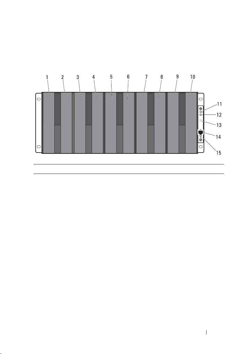
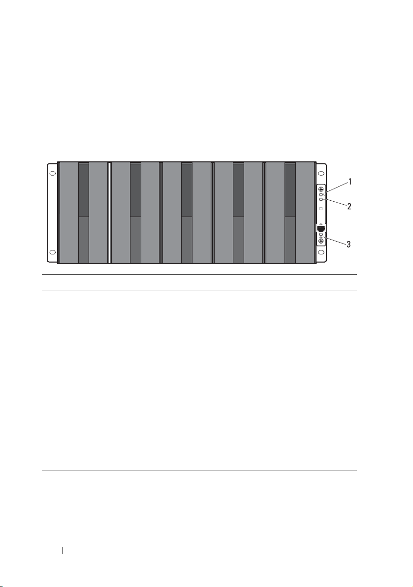
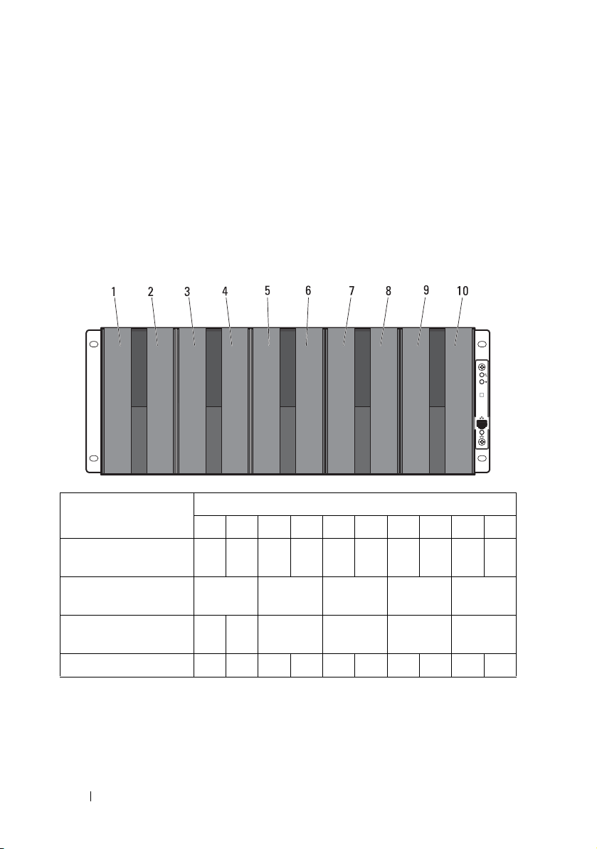
Front-Panel Features and Indicators
Figure 1-1. Front-Panel Features and Indicators
Item Feature Icon Description
1 - 10 Sled bays 1 to 10 Installs up to five C8220X compute sleds,
ten C8220 compute sleds, five C8000XD
storage sleds, or a mixture of differing sled
types.
NOTE: Sled bays 1 and 2 support installation
of two C8220 or one C8220X compute sleds.
For server enclosure with internal power
source, C8000XD storage sleds install in sled
bays 3 to 10 only.
Sled bays 5 and 6 Installs up to two power sleds or two C8220
compute sleds or a combination of the two
sled types.
NOTE: If the enclosure is configured with
only one power sled, a C8220 compute sled
or a power sled blank must be mounted into
the adjacent sled bay.
NOTE: The sled bays must always be
populated with either a sled or a sled blank
to ensure proper system cooling.
About the System 13
Page 14

Item Feature Icon Description
11 Chassis status
indicator
12 Chassis
identification
indicator
13 Thermal sensor Monitors the inlet ambient temperature.
14 Ethernet connector Embedded 10/100 Mbit NIC connector.
Indicates the power and health status of
the whole system.
Lights blue when the chassis ID signal is
generated.
15 NIC link/activity
indicator
Indicates state of the network link and
activity.
14 About the System
Page 15
Back-Panel Features and Indicators
1
22
3
4
5
6
7
8910
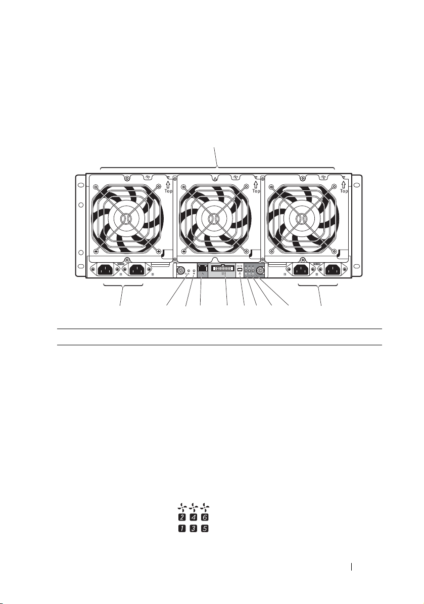
Figure 1-2. Back-Panel Features and Indicators — Server Enclosure with Internal
Power Source
Item Feature Icon Description
1 Fan modules Provides cooling solution to the enclosure.
2 AC power sockets Connect the power cables to these power
sockets. When connected to a power
source, main power is automatically
distributed to the enclosure.
NOTE: Always connect the enclosure's AC
3, 4, 5 Fan fault indicators
1 to 6
power sockets to a single power source,
switch, or PDU.
NOTE: Before installing a compute or
storage sled to the front of the enclosure,
install the power sleds and connect power to
the enclosure.
Indicates the function status of the system
fans.
About the System 15
Page 16
Item Feature Icon Description
1
2
3
4
5
6
789
10
6Service mode
button
Press this button within 4 seconds to enter
service mode.
7External PDU
connector
8 BMC management
port
9Chassis
identification
indicator
10 Power/event
indicator
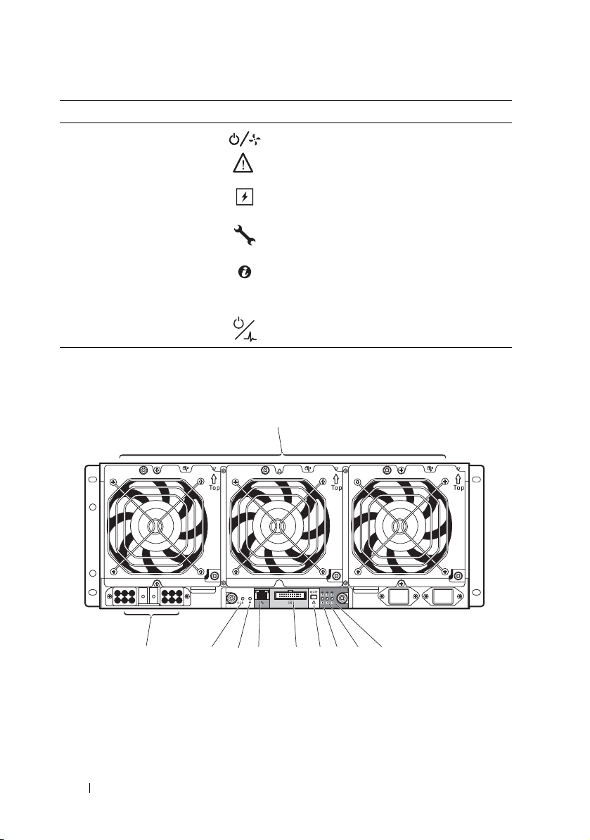
Figure 1-3. Back-Panel Features and Indicators — Server Enclosure with External
Power Source
Connects to a PDU control connector.
Dedicated management port.
Lights blue when the chassis ID signal is
generated.
Indicates the power and health status of the
enclosure.
16 About the System
Page 17
Item Feature Icon Description
1 Fan modules Provides cooling solution to the enclosure.
2, 3, 4 Fan fault indicators
1 to 6
Indicates the function status of the system
fans.
5Service mode
button
6External PDU
connector
7 BMC management
port
8 Chassis
identification
indicator
9Power/event
indicator
10 DC power socket Connect the DC power cable to this power
Press this button within 4 seconds to enter
service mode.
Connects to a PDU control connector.
Dedicated management port.
Lights blue when the chassis ID signal is
generated.
Indicates the power and health status of the
enclosure.
socket. When connected to an external
PDU, main power is automatically
distributed to the enclosure.
NOTE: Always connect the enclosure's DC
power socket to a PDU.
NOTE: Before installing a compute or
storage sled to the front of the enclosure,
connect power to the enclosure.
About the System 17
Page 18
Server Enclosure Indicator Codes
The indicators on the front and back of the server enclosure displays
operational status of the enclosure, fan modules, and chassis controller
boards.
Figure 1-4. Server Enclosure Front-Panel Indicators
Item Indicator Color Status Indicator Code
1 Chassis status
indicator
2 Chassis
identification
indicator
3 NIC link/activity
indicator
Green Solid Indicates a valid power source is
connected to the server enclosure
and that the enclosure is
operational.
Off Off Power is not connected.
Amber Blinking Indicates a fault event occurred.
Blue Blinking Indicates a chassis ID signal is
generated.
Blue Off Chassis ID signal is not generated.
Green Solid Linking at 100 Mbps speed
(maximum).
Green Blinking Transmit or receive activity.
Off Off No activity.
18 About the System
Page 19
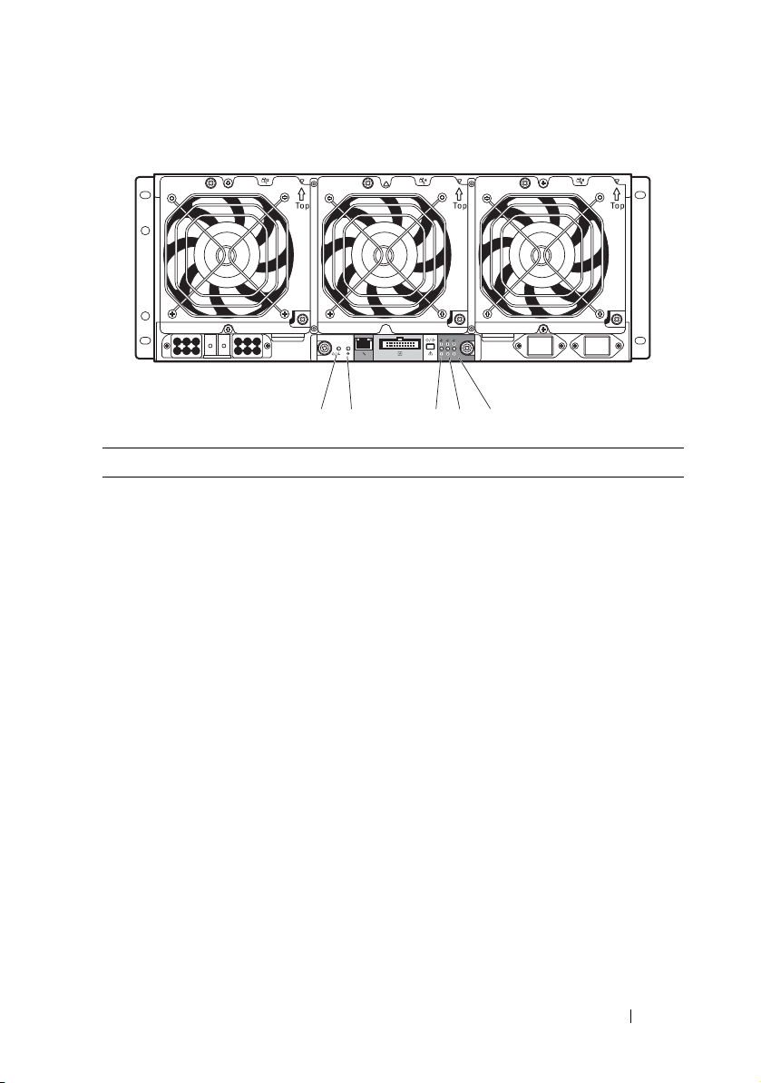
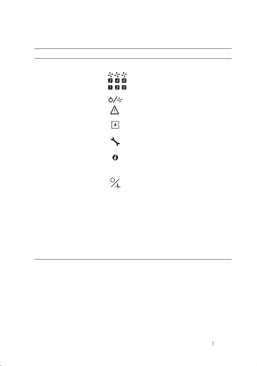
Figure 1-5. Server Enclosure Back-Panel Indicators
5
4
3
21
Item Indicator Color Status Indicator Code
1Power/event
indicator
2Chassis
identification
indicator
3 Fan 1 and 2
fault indicator
4 Fan 3 and 4
fault indicator
Green Solid Indicates a valid power source is
connected to the server enclosure
and that the enclosure is
operational and power is applied to
the fan controller board.
Green Blinking Power is connected to the
enclosure but the managed devices’
or sleds’ power is off.
Amber Blinking Indicates a fault event occurred.
Off Off Power is not connected.
Blue Blinking Indicates a chassis ID signal is
generated.
Blue Off Chassis ID signal is not generated.
Amber Blinking Indicates a fault event occurred in
fans 1 and 2.
Off Off Fans 1 and 2 are operational.
Amber Blinking Indicates a fault event occurred in
fans 3 and 4.
Off Off Fans 3 and 4 are operational.
About the System 19
Page 20
Item Indicator Color Status Indicator Code
5 Fan 5 and 6
fault indicator
Amber Blinking Indicates a fault event occurred in
fans 5 and 6.
Off Off Fans 5 and 6 are operational.
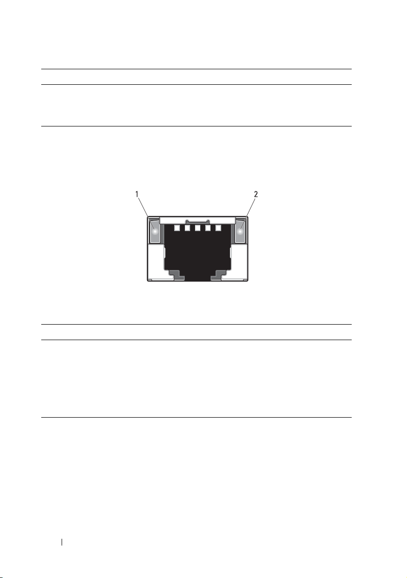
NIC Indicator Codes
Figure 1-6. NIC Indicators (Front-Panel Ethernet Connector)
1 link indicator 2 activity indicator
Indicator Status Indicator Code
Link indicator Solid amber Linking at 10 Mbps port speed
Solid green Linking at 100 Mbps port speed (maximum)
Activity
indicator
Solid green No activity
Blinking green Transmit or receive activity
Off Idle
20 About the System
Page 21
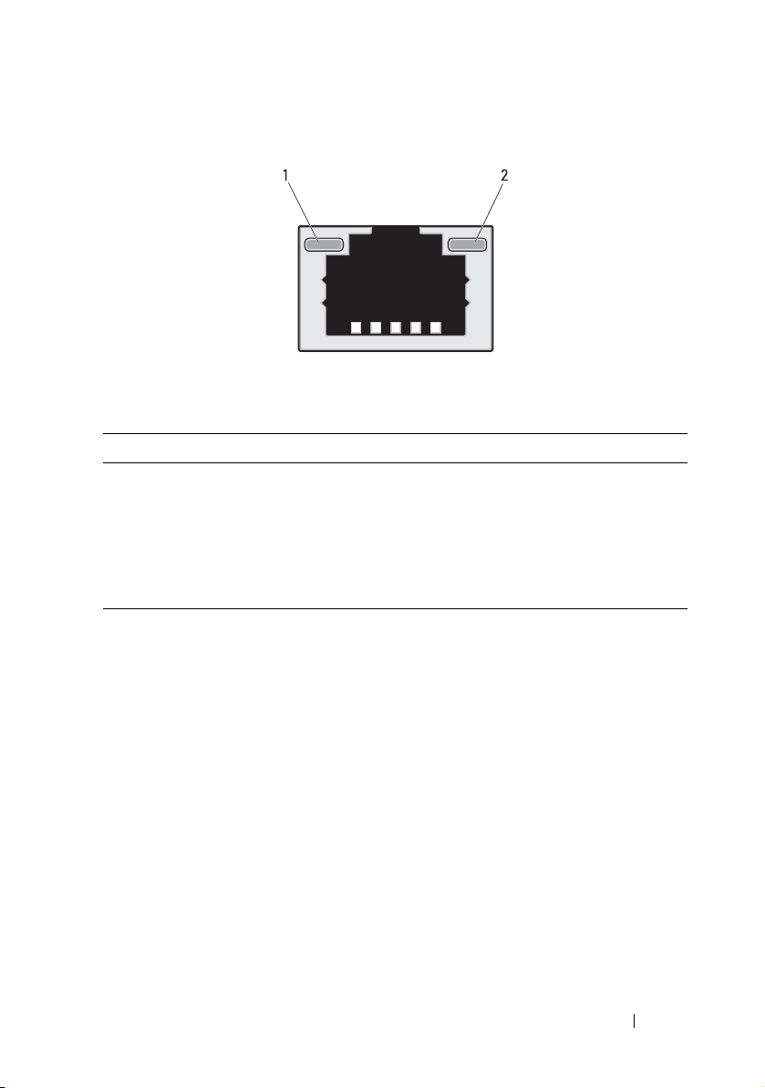
Figure 1-7. NIC Indicators (BMC management port)
1 link indicator 2 activity indicator
Indicator Status Indicator Code
Link indicator Blinking amber Linking at 10 Mbps port speed
Blinking green Linking at 100 Mbps port speed (maximum)
Activity
indicator
Solid green No activity
Blinking green Transmit or receive activity
Off Idle
About the System 21
Page 22
Sled Bay Numbering
The front of the server enclosure is divided into ten vertical bays. A C8220
single-wide compute sled occupies one sled bay in the server enclosure and a
C8220X double-wide compute sled or C8000XD storage sled occupies two
sled bays in the server enclosure. When installing a sled module into the
server enclosure, you should install the sled module in sled bay 1 first, then
work toward the right of the enclosure.
Figure 1-8. Sled Bay Numbering
Sled Bays
Sled module type
C8220 single-wide
12345
compute sled
C8220X double-wide
compute sled
C8000XD storageb
sled
Power sled
a. Sled bays 5 and 6 support installation of two power sleds or two C8220 compute sleds or a
combination of the two sled types.
b. For server enclosure with internal power source, install C8000XD storage sleds in sled bays 3 to 10
only.
c. Install power sleds in sled bays 5 and 6 only.
c
a6a
78910
22 About the System
Page 23
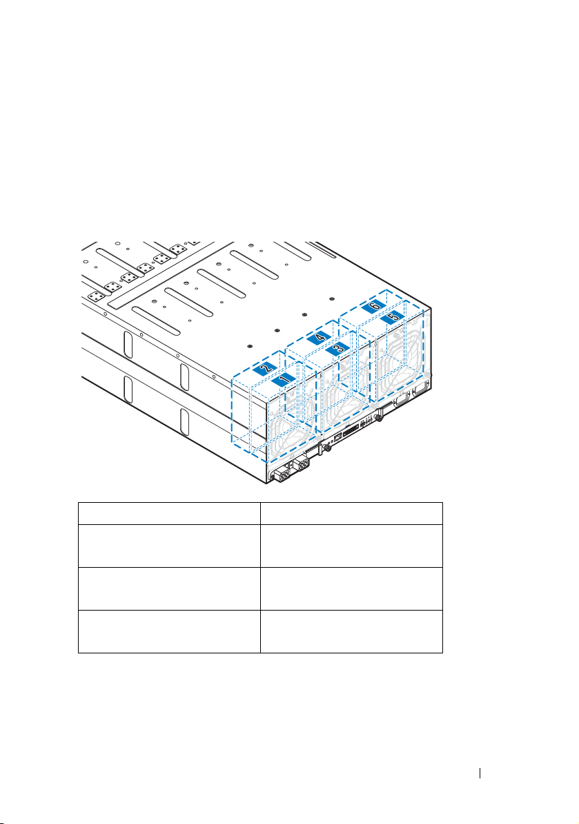
Fan Bay Numbering
The back of the PowerEdge C8000 server enclosure includes three hotswappable fan modules that provide the system with a redundant cooling
source. Each fan module contains two cooling fans. All three fan modules
must be installed at all times to ensure proper cooling.
Figure 1-9. Fan Bay Numbering
Fan Bay Cooling Fans
Fan module 1 Fan 2
Fan 1
Fan module 2 Fan 4
Fan 3
Fan module 3 Fan 6
Fan 5
About the System 23
Page 24
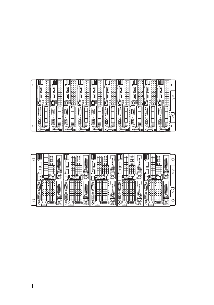
Sled Module Configuration
The following illustrations are sample sled module configurations available on
the PowerEdge C8000 server enclosure.
Figure 1-10. C8220 Single-Wide Compute Sleds
Figure 1-11. C8220X Double-Wide Compute Sleds
24 About the System
Page 25
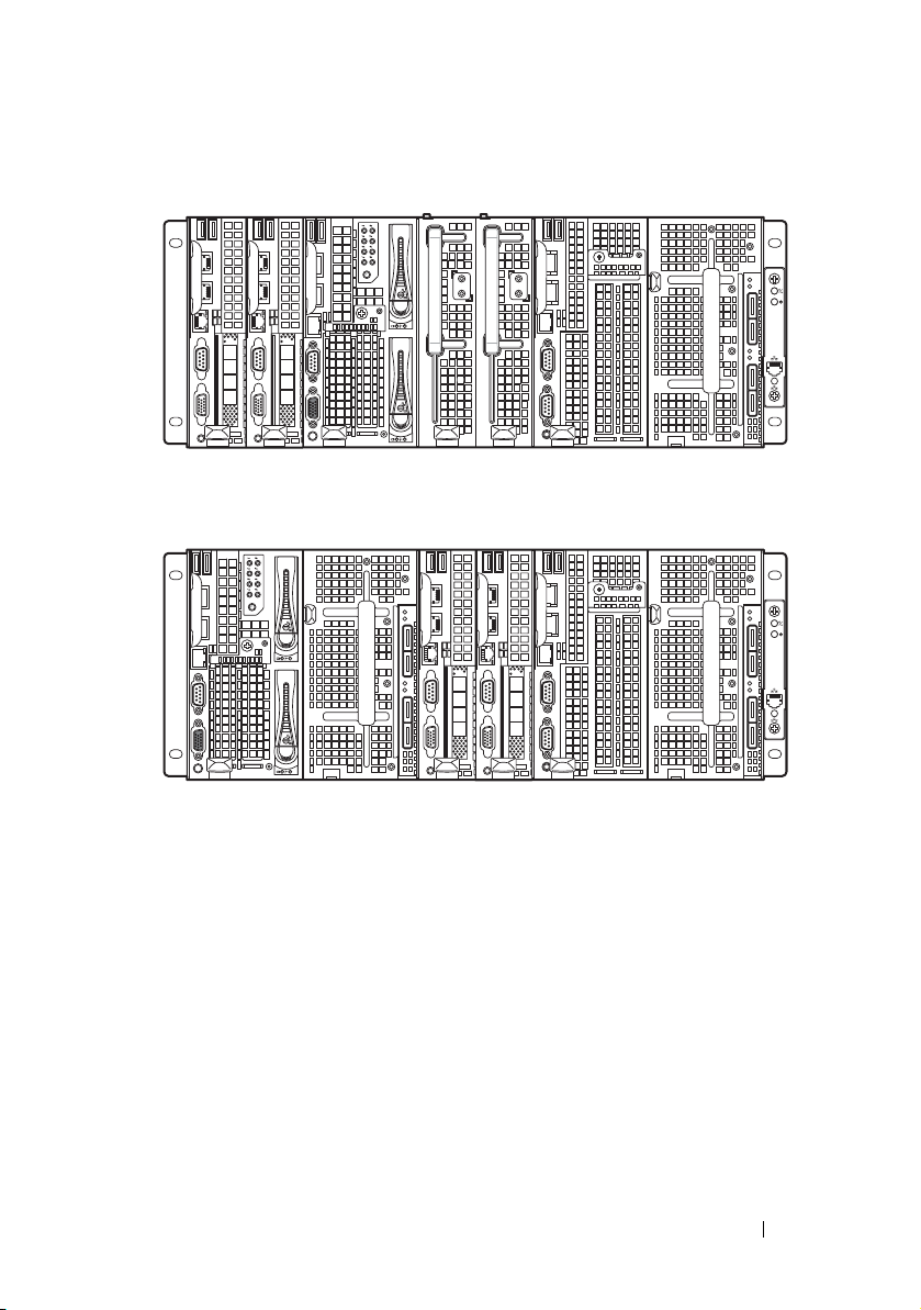
Figure 1-12. Mixed Sleds — Server Enclosure with Internal Power Source
Figure 1-13. Mixed Sleds — Server Enclosure with External Power Source
About the System 25
Page 26
Sled Features
Compute Sleds
The PowerEdge C8000 server enclosure holds up to ten single-wide compute
sleds or five double-wide compute sleds. Each compute sled is equivalent to a
standard server built with a processor(s), memory, network interface,
baseboard management controller, and local hard-drive storage.
Single-Wide Compute Sled
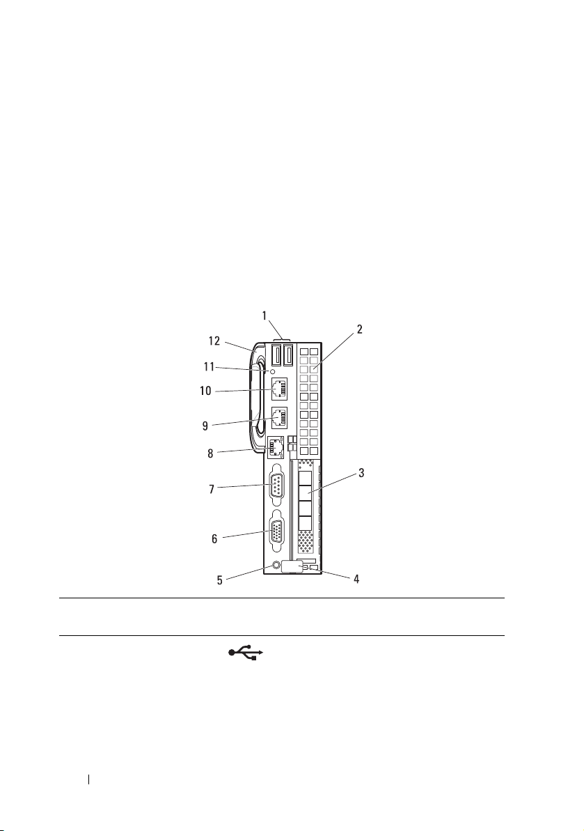
Figure 1-14. Sled Features — C8220 Single-Wide Compute Sled
Item Indicator, Button, or
Connector
1 USB connectors Connects USB devices to the sled. The
2 Mezzanine card
expansion slot
3 Low profile PCIe
expansion slot
Icon Description
ports are USB 2.0 compliant.
Installs an I/O module mezzanine card.
Installs a low profile PCI Express x16 card.
26 About the System
Page 27

Item Indicator, Button, or
Connector
4 Release latch Press to release the sled from the enclosure.
5Power-on indicator/
power button
Icon Description
The power-on indicator lights when the
sled power is on. The power-on indicator
lights amber when the system critical event
occurs.
NOTE: The power-on indicator lights amber
according to critical system error log (SEL)
assertion. If the SEL is full or a deassertion
event occurred while sensor monitoring is
paused (e.g. fan monitoring is paused during
system power off), the power-on indicator
turns amber. To turn off an amber LED and
reset the power-on indicator to normal
condition (solid green), either perform a
BMC cold reset or reseat the sled in the
server enclosure.
The power button turns the compute
sled on.
NOTES:
• When powering on the sled, the video
monitor can take from several seconds
to over 2 minutes to display an image,
depending on the amount of memory
installed in the system.
• On ACPI-compliant operating systems,
turning off the sled using the power
button causes the sled to perform a
graceful shutdown before power to the
sled is turned off.
• To force an ungraceful shutdown, press
and hold the power button for five
seconds.
About the System 27
Page 28
Item Indicator, Button, or
2
1
Connector
6 VGA connector Connects a VGA display to the system.
7 Serial connector Connects a serial device to the system.
Icon Description
8 BMC management
port
9 Ethernet connector 2 Embedded 10/100/1000 Mbit NIC
10 Ethernet connector 1 Embedded 10/100/1000 Mbit NIC
11 Sled identification
indicator
12 Handle Hold to pull the sled from the enclosure.
Dedicated management port.
connector.
connector.
Lights blue to identify a particular sled and
system board.
28 About the System
Page 29
Double-Wide Compute Sled
The C8220X double-wide compute sled includes two types of configuration,
a double-wide compute sled with front-access 2.5-inch hot-plug hard-drives
and a double-wide compute sled with general-purpose graphics processing
unit (GPGPU).
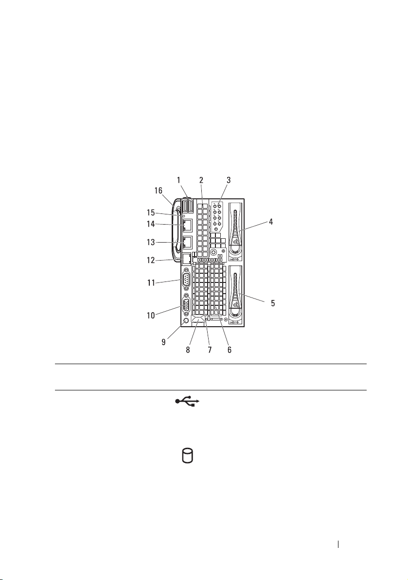
Figure 1-15. Sled Features — C8220X Double-Wide Compute Sled with Front-Access
Hot-Plug Hard-Drives
Item Indicator, Button, or
Connector
1 USB connectors Connects USB devices to the sled. The
2 Mezzanine card
expansion slot
3 Hard-drive indicators
0 to 7
4, 5 Hard-drive bay Installs two 2.5-inch hot-plug hard-drives.
6, 7 Low profile PCIe
expansion slots
Icon Description
ports are USB 2.0 compliant.
Installs an I/O module mezzanine card.
Indicates drive activity and status.
Installs up to two low profile PCI Express
x8 card when plugged into horizontal
expansion card connectors.
About the System 29
Page 30

Item Indicator, Button, or
Connector
8 Sled release latch Press to release the sled from the
9Power-on indicator/
power button
Icon Description
enclosure.
The power-on indicator lights when the
sled power is on.The power-on indicator
lights amber when the system critical
event occurs.
NOTE: The power-on indicator lights amber
according to critical system error log (SEL)
assertion. If the SEL is full or a deassertion
event occurred while sensor monitoring is
paused (e.g. fan monitoring is paused during
system power off), the power-on indicator
turns amber. To turn off an amber LED and
reset the power-on indicator to normal
condition (solid green), either perform a
BMC cold reset or reseat the sled in the
server enclosure.
The power button turns the compute sled
on.
NOTES:
• When powering on the sled, the video
monitor can take from several seconds
to over 2 minutes to display an image,
depending on the amount of memory
installed in the system.
• On ACPI-compliant operating
systems, turning off the sled using the
power button causes the sled to
perform a graceful shutdown before
power to the sled is turned off.
• To force an ungraceful shutdown, press
and hold the power button for five
seconds.
10 VGA connector Connects a VGA display to the system.
11 Serial connector Connects a serial device to the system.
30 About the System
Page 31

Item Indicator, Button, or
2
1
1
3
4
5
6
7
8
9
10
11
2
12
Connector
12 BMC management
port
13 Ethernet connector 2 Embedded 10/100/1000 Mbit NIC
14 Ethernet connector 1 Embedded 10/100/1000 Mbit NIC
15 Sled identification
indicator
16 Handle Hold to pull the sled from the enclosure.
Figure 1-16. Sled Features — C8220X Double-Wide Compute Sled with GPGPU
Icon Description
Dedicated management port.
connector.
connector.
Lights blue to identify a particular sled
and system board.
Item Indicator, Button, or
1 USB connectors Connects USB devices to the sled. The ports
2 Mezzanine card
Connector
expansion slot
Icon Description
are USB 2.0 compliant.
Installs an I/O module mezzanine card.
About the System 31
Page 32

Item Indicator, Button, or
Connector
3 Sled cover/ GPGPU
card assembly
4 Sled release latch Press to release the sled from the enclosure.
5Power-on indicator/
power button
Icon Description
Installs up to two GPGPU cards when
plugged into horizontal GPGPU card risers.
The power-on indicator lights when the sled
power is on.The power-on indicator lights
amber when the system critical event occurs.
NOTE: The power-on indicator lights amber
according to critical system error log (SEL)
assertion. If the SEL is full or a deassertion
event occurred while sensor monitoring is
paused (e.g. fan monitoring is paused during
system power off), the power-on indicator turns
amber. To turn off an amber LED and reset the
power-on indicator to normal condition (solid
green), either perform a BMC cold reset or
reseat the sled in the server enclosure.
The power button turns the compute sled on.
NOTES:
• When powering on the sled, the video
monitor can take from several seconds to
over 2 minutes to display an image,
depending on the amount of memory
installed in the system.
• On ACPI-compliant operating systems,
turning off the sled using the power
button causes the sled to perform a
graceful shutdown before power to the
sled is turned off.
• To force an ungraceful shutdown, press
and hold the power button for five
seconds.
6 VGA connector Connects a VGA display to the system.
7 Serial connector Connects a serial device to the system.
32 About the System
Page 33

Item Indicator, Button, or
2
1
Connector
8 BMC management
port
9 Ethernet connector
2
10 Ethernet connector
1
11 Sled identification
indicator
12 Handle Hold to pull the sled from the enclosure.
Icon Description
Dedicated management port.
Embedded 10/100/1000 Mbit NIC connector.
Embedded 10/100/1000 Mbit NIC connector.
Lights blue to identify a particular sled and
system board.
About the System 33
Page 34
Storage Sleds
1
2
3
4
5
6
7
8
910
11
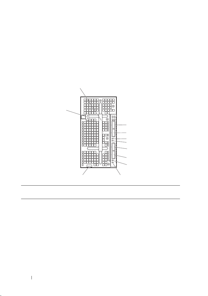
The C8000XD storage sled is a direct attached storage for the server
enclosure. The storage sled provides dedicated data storage to a C8220X sled
or C8220 sled. Each storage sled supports up to a maximum of 12 x 3.5-inch/
2.5-inch hard-drives or 24 x 2.5-inch SSD hard-drives.
Figure 1-17. Sled Features — C8000XD Storage Sled
Item Indicator, Button, or
Connector
1 Handle Hold to pull the hard-drive cage from the
2 Mini-SAS connector A2 Connects to a compute sled’s host bus
3 Mini-SAS connector A1 Connects to a compute sled’s HBA or
34 About the System
Icon Description
sled.
adapter (HBA) or RAID controller card.
RAID controller card.
Page 35

Item Indicator, Button, or
Connector
4, 8 Sled power/status
indicator
5, 9 Sled identification
indicator
6 Mini-SAS connector B2 Connects to a compute sled’s HBA or
7 Mini-SAS connector B1 Connects to a compute sled’s HBA or
10 Sled release tab Press to release the sled from the
11 Hard-drive cage release
latch
Icon Description
The power-on indicator lights green
when the sled power is on and power is
applied to the SAS expander board.
The power-on indicator alternately lights
green and blinks amber when a critical
event occurs.
Lights blue to identify a particular miniSAS connector and sled.
RAID controller card.
RAID controller card.
enclosure.
Press to release the hard-drive cage from
the sled.
About the System 35
Page 36

Power Sleds
You can install up to two hot-swappable power sleds in the server enclosure
that supports internal power source. Each power sled installs up to two
1400 W power supply modules that are capable of delivering 2800 W power
to the server enclosure at an input range of 200-240 V.
Figure 1-18. Sled Features — Power Sled
36 About the System
Page 37

Item Indicator, Button, or
Connector
1 PSU1/3 status
indicator
2 PSU2/4 status
indicator
3 Handle Hold to pull the sled from the enclosure.
4 Release latch Press to release the sled from the enclosure.
Icon Description
The PSU1/3 status indicator lights green
indicating that a valid power source is
connected to the power supply and that
power supply is operational.
The PSU1/3 status indicator lights amber
indicating a problem with the PSU module.
• PSU module fan locked (15 s)
• PSU module over temperature protection
(OTP)
• PSU module over current protection
(OCP)
• PSU module over voltage protection
(OVP)
• PSU module under voltage protection
(UVP)
The PSU2/4 status indicator lights green
indicating that a valid power source is
connected to the power supply and that
power supply is operational.
The PSU2/4 status indicator lights amber
indicating a problem with the PSU module.
• PSU module fan locked (15 s)
• PSU module over temperature protection
(OTP)
• PSU module over current protection
(OCP)
• PSU module over voltage protection
(OVP)
• PSU module under voltage protection
(UVP)
About the System 37
Page 38

Service Tag
The following illustrations provide location of the Service Tag number on the
server enclosure, compute sleds, and storage sleds.
Server Enclosure
Figure 1-19. Service Tag Location for Server Enclosure
38 About the System
Page 39

Sleds
Figure 1-20. Service Tag Location for C8220 Single-Wide Compute Sled
Figure 1-21. Service Tag Location for C8220X Double-Wide Compute Sled with 3.5-inch
(4-Drive Bay) Hard-Drives
About the System 39
Page 40

Figure 1-22. Service Tag Location for C8220X Double-Wide Compute Sled with 2.5-inch
(8-Drive Bay) Hard-Drives
Figure 1-23. Service Tag Location for C8220X Double-Wide Compute Sled with GPGPU
40 About the System
Page 41

Figure 1-24. Service Tag Location for C8000XD Storage Sled
About the System 41
Page 42

POST Error Codes
Collecting System Event Log for Investigation
Whenever possible, the system BIOS will output the current boot progress
codes on the video screen. Progress codes are 32-bit quantities plus optional
data. The 32-bit numbers include class, subclass, and operation information.
The class and subclass fields point to the type of hardware that is being
initialized. The operation field represents the specific initialization activity.
Based on the data bit availability to display progress codes, a progress code
can be customized to fit the data width. The higher the data bit, the higher
the granularity of information that can be sent on the progress port. The
progress codes may be reported by the system BIOS or option ROMs.
The Response section in the following table may be divided into 3 types:
• Warning or Not an error – The message is displayed on the screen. An error
record is logged to the SEL. The system will continue booting with a
degraded state. The user may want to replace the erroneous unit.
• Pause – The message is displayed on the screen, an error is logged to the
SEL, and user input is required to continue. The user can take immediate
corrective action or choose to continue booting.
• Halt – The message is displayed on the screen, an error is logged to the
SEL, and the system cannot boot unless the error is resolved. The user
needs to replace the faulty part and restart the system.
Error
Code
0010h Local Console
0011h Local Console
Error Message Response Error Cause Corrective Actions
Resource
Conflict
Controller Error
42 About the System
Pau s e Video d evice
initialization
failed
Pau s e Video d evice
initialization
failed
See "Troubleshooting the
Video Subsystem" on
page 252.
If the problem persists, see
"Getting Help" on page 289.
See "Troubleshooting the
Video Subsystem" on
page 252.
If the problem persists, see
"Getting Help" on page 289.
Page 43

Error
Code
0012h Local Console
0013h ISA IO
0014h ISA IO Resource
0015h ISA IO
0016h ISA Floppy
0017h ISA Floppy
0018h ISA Floppy
Error Message Response Error Cause Corrective Actions
Output Error
Controller Error
Conflict
Controller Error
Controller Error
Input Error
Output Error
Pau s e Video d evice
initialization
failed
Pau s e ISA devi c e
initialization
failed
Pau s e ISA devi c e
initialization
failed
Pau s e ISA devi c e
initialization
failed
Pause Floppy device
initialization
failed
Pause Floppy device
initialization
failed
Pause Floppy device
initialization
failed
See "Troubleshooting the
Video Subsystem" on
page 252.
If the problem persists, see
"Getting Help" on page 289.
See "Troubleshooting
Expansion Cards" on
page 270.
If the problem persists, see
"Getting Help" on page 289.
See "Troubleshooting
Expansion Cards" on
page 270.
If the problem persists, see
"Getting Help" on page 289.
See "Troubleshooting
Expansion Cards" on
page 270.
If the problem persists, see
"Getting Help" on page 289.
See "Troubleshooting a USB
Device" on page 252.
If the problem persists, see
"Getting Help" on page 289.
See "Troubleshooting a USB
Device" on page 252.
If the problem persists, see
"Getting Help" on page 289.
See "Troubleshooting a USB
Device" on page 252.
If the problem persists, see
"Getting Help" on page 289.
About the System 43
Page 44

Error
Code
0019h USB Read Error Pause USB port
001Ah USB Write Error Pause USB port
001Bh USB Interface
001Ch Mouse Interface
001Eh Keyboard Not
001Fh Keyboard
Error Message Response Error Cause Corrective Actions
initialization
failed
initialization
failed
Pau s e USB port
Error
Pau s e Mouse de vice
Error
Pause No keyboard
Detected
Pau se Key board
Controller Error
initialization
failed
initialization
failed
detected
controller
initialization
failed
See "Troubleshooting a USB
Device" on page 252.
If the problem persists, see
"Getting Help" on page 289.
See "Troubleshooting a USB
Device" on page 252.
If the problem persists, see
"Getting Help" on page 289.
See "Troubleshooting a USB
Device" on page 252.
If the problem persists, see
"Getting Help" on page 289.
To enable USB device, see
"USB Configuration" on
page 105.
See "Troubleshooting a USB
Device" on page 252.
If the problem persists, see
"Getting Help" on page 289.
To enable USB device, see
"USB Configuration" on
page 105.
See "Troubleshooting a USB
Device" on page 252.
If the problem persists, see
"Getting Help" on page 289.
See "Troubleshooting a USB
Device" on page 252.
If the problem persists, see
"Getting Help" on page 289.
44 About the System
Page 45

Error
Code
0020h Keyboard Stuck
0021h Keyboard
0023h Memory
0024h Memory
0025h Memory Non-
0026h MP Service Self
0027h PCI IO
Error Message Response Error Cause Corrective Actions
Key Error
Locked Error
Correctable
Error
Uncorrectable
Error
Specific Error
Tes t Er r or
Controller Error
Pau s e Keybo ard ke y
stuck
Pau se Key board
locked
Pau se Memor y
correctable
error detected
Pau se Memor y
uncorrectable
error detected
Pause Memory non-
specific error
detected
Pause MP service self
test error
detected
Pau s e PCI devi c e
initialization
failed
Disconnect and reconnect the
keyboard to the compute sled.
If the problem persists, see
"Getting Help" on page 289.
Disconnect and reconnect the
keyboard to the compute sled.
If the problem persists, see
"Getting Help" on page 289.
Remove AC power to the
system for 10 seconds and
restart the system.
See "Troubleshooting System
Memory" on page 267.
If the problem persists, see
"Getting Help" on page 289.
See "Troubleshooting System
Memory" on page 267.
If the problem persists, see
"Getting Help" on page 289.
See "Troubleshooting System
Memory" on page 267.
If the problem persists, see
"Getting Help" on page 289.
See "Troubleshooting
Processors" on page 270.
If the problem persists, see
"Getting Help" on page 289.
See "Troubleshooting
Expansion Cards" on
page 270.
If the problem persists, see
"Getting Help" on page 289.
About the System 45
Page 46

Error
Code
0028h PCI IO Read
0029h PCI IO Write
002Ah Serial Port Not
002Bh Serial Port
002Ch Serial Port Input
002Dh Serial Port
002Eh Microcode
Error Message Response Error Cause Corrective Actions
Error
Error
Detected
Controller Error
Error
Output Error
Update Error
Pau s e PCI devi c e
initialization
failed
Pau s e PCI devi c e
initialization
failed
Pau s e Serial de v ice
initialization
failed
Pau s e Serial de v ice
initialization
failed
Pau s e Serial de v ice
initialization
failed
Pau s e Serial de v ice
initialization
failed
Pause Processor
microcode
update error
See "Troubleshooting
Expansion Cards" on
page 270.
If the problem persists, see
"Getting Help" on page 289.
See "Troubleshooting
Expansion Cards" on
page 270.
If the problem persists, see
"Getting Help" on page 289.
See "Troubleshooting a Serial
I/O Device" on page 253.
If the problem persists, see
"Getting Help" on page 289.
See "Troubleshooting a Serial
I/O Device" on page 253.
If the problem persists, see
"Getting Help" on page 289.
See "Troubleshooting a Serial
I/O Device" on page 253.
If the problem persists, see
"Getting Help" on page 289.
See "Troubleshooting a Serial
I/O Device" on page 253.
If the problem persists, see
"Getting Help" on page 289.
Check microcode. A BIOS
update is required.
If the problem persists, see
"Getting Help" on page 289.
46 About the System
Page 47

Error
Code
002Fh No Microcode
8012h SATA 0 Device
8013h SATA 1 Device
8014h SATA 2 Device
8015h SATA 3 Device
Error Message Response Error Cause Corrective Actions
Be Updated
Not Found
Not Found
Not Found
Not Found
Pause Processor
microcode load
failed
Pause SATA 0 device
not found
Pause SATA 1 device
not found
Pause SATA 2 device
not found
Pause SATA 3 device
not found
Ensure that your processors
match and conform to the
type described in the
processor technical
specifications outlined in
your system’s Getting Started
Guide.
Check if the SATA port 0 is
enabled. See "SATA
Configuration" on page 95.
Install a SATA device to SATA
port 0.
If the problem persists, see
"Getting Help" on page 289.
Check if the SATA port1 is
enabled. See "SATA
Configuration" on page 95.
Install a SATA device to SATA
port 1.
If the problem persists, see
"Getting Help" on page 289.
Check if the SATA port 2 is
enabled. See "SATA
Configuration" on page 95.
Install a SATA device to SATA
port 2.
If the problem persists, see
"Getting Help" on page 289.
Check if the SATA port 3 is
enabled. See "SATA
Configuration" on page 95.
Install a SATA device to SATA
port 3.
If the problem persists, see
"Getting Help" on page 289.
About the System 47
Page 48

Error
Code
8016h SATA 4 Device
8017h SATA 5 Device
8018h Sparing Mode is
8019h Mirror Mode is
8020h Supervisor and
Error Message Response Error Cause Corrective Actions
Not Found
Not Found
not be
Configured!!,
Please check
Memory
Configuration!!
not be
Configured!!,
Please check
Memory
Configuration!!
User Passwords
have been
cleared
Pause SATA 4 device
not found
Pause SATA 5 device
not found
Pau se Memo ry
Sparing Mode
Failed
Pause Memory Mirror
Mode Failed
Pau s e Supervi s or and
User Passwords
have been
cleared
Check if the SATA port 4 is
enabled. See "SATA
Configuration" on page 95.
Install a SATA device to SATA
port 4.
If the problem persists, see
"Getting Help" on page 289.
Check if the SATA port 5 is
enabled. See "SATA
Configuration" on page 95.
Install a SATA device to SATA
port 5.
If the problem persists, see
"Getting Help" on page 289.
Check if the memory
configuration is set to Sparing
mode. See "Memory
Configuration" on page 92.
If the problem persists, see
"Getting Help" on page 289.
Check if the memory
configuration is set to Sparing
mode. See "Memory
Configuration" on page 92.
If the problem persists, see
"Getting Help" on page 289.
Reset password. See the
compute sled’s
documentation for more
information.
If the problem persists, see
"Getting Help" on page 289.
48 About the System
Page 49

Error
Code
8021h CMOS Battery
8100h Memory device
Error Message Response Error Cause Corrective Actions
Error
disabled by
BIOS
Pause No CMOS
battery
Pau se Memor y
Device Error
See the compute sled’s
documentation for more
information.
See "Troubleshooting System
Memory" on page 267.
If the problem persists, see
"Getting Help" on page 289.
About the System 49
Page 50

System Event Log
Processor Error
Message: “Processor Sensor, IERR error, Processor 1”
Table 1-1. Processor Error
Byte Field Value Description
1 NetFunLun 10h
2 Platform Event Command 02h
3 Generator ID 01h Generated by BIOS
4 Event Message Format
Ve rs io n
5 Sensor Type 07h Processor
6 Sensor Number 04h Processor Sensor Number
7 Event Direction Event Type 6Fh Bit 7: 0 = Assert Event Bit 6: 0 =
8 Event Data1 AXh 00h: IERR 01h: Thermal Trip
9 Event Data2 XXh 00h: Processor1
10 Event Data3 FFh FFh: Not Present
04h Event Message Format Revision.
04h for this specification
(depends on platform)
Event Type Code
02h: FRB1/BIST Failure
03h: FRB2/Hang in POST Failure
04h: FBR3/Processor
Startup/Initialization Failure
0Ah: Processor Automatically
Throttled
01h: Processor2
02h: Processor3
04h: Processor4
50 About the System
Page 51

Memory Ecc
Message: “Memory Sensor, Correctable ECC error, SBE warning threshold,
CPU1 DIMM_A1”
Table 1-2. Memory ECC
Byte Field Value Description
1 NetFunLun 10h
2 Platform Event Command 02h
3 Generator ID 01h Generated by BIOS
4 Event Message Format
Ve rs io n
5 Sensor Type 0Ch Memory
6 Sensor Number 60h Memory Sensor Number (depend
7 Event Direction Event Type 6Fh Bit 7: 0 = Assert Event
8 Event Data1 AXh 00h: Correctable ECC Error
04h Event Message Format Revision.
04h for this specification
on platform)
Bit 6: 0 = Event Type Code
01h: Uncorrectable ECC Error
03h: Memory Scrub Failed
04h: Memory Device Disabled
08h: Spare
About the System 51
Page 52

Table 1-2. Memory ECC
Byte Field Value Description
9 Event Data2 XXh Bit 7:4
0x00: SBE warning threshold
0x01: SBE critical threshold
0x0F: Unspecified
Bit 3:0
0x00: CPU1 DIMM A1-8 slots
(1~8)
0x01: CPU2 DIMM B1-8 slots
(9~16)
0x02: CPU3 DIMM C1-8 slots
(17~24)
0x03: CPU4 DIMM D1-8 slots
(25~32) And so on…
10 Event Data3 XXh DIMM bit-map location of bits
Bit 0=1: DIMM1 error event
Bit 1=1: DIMM2 error event …
Bit7=1: DIMM8 error event
52 About the System
Page 53

PCIe Error
Message: “Critical Interrupt Sensor, PCI PERR, Device#, Function#,
Bus#”
Table 1-3. PCIe Error
Byte Field Value Description
1 NetFunLun 10h
2 Platform Event Command 02h
3 Generator ID 01h Generated by BIOS
4 Event Message Format
Ve rs io n
5 Sensor Type 13h Critical Interrupt
6 Sensor Number 73h PCI Sensor ID (depend on
7 Event Direction Event Type 6Fh Bit 7: 0 = Assert Event
8 Event Data1 AXh 04h: PCI PERR
9 Event Data2 XXh Bit 7:3Device Number
10 Event Data3 XXh Bit 7:0 Bus Number
04h Event Message Format Revision.
04h for this specification
platform)
Bit 6: 0 = Event Type Code
05h: PCI SERR
07h: Bus Correctable Error
08h: Bus Uncorrectable Error
0Ah: Bus Fatal Error
Bit 2:0Function Number
About the System 53
Page 54

IOH Core Error
Message: “Critical Interrupt Sensor, Fatal Error, xxxx bit, QPI[0] Error”
Table 1-4. IOH Core Error
Byte Field Value Description
1 NetFunLun 10h
2 Platform Event Command 02h
3 Generator ID 01h Generated by BIOS
4 Event Message Format
Ve rs io n
5 Sensor Type C0h OEM Defined Interrupt
6 Sensor Number XXh 71h: QPI Sensor ID (depend on
7 Event Direction Event Type 6Fh Bit 7: 0 = Assert Event Bit 6: 0 =
8 Event Data1 AXh 07h: Core
9 Event Data2 XXh Local Error Bit
10 Event Data3 XXh 00h: QPI[0] Error
04h Event Message Format Revision.
04h for this specification
platform)
72h: INT Sensor ID (depend on
platform)
Event Type Code
08h: Non-Fatal
0Ah: Fatal
01h: QPI[1] Error
02h: QPI[2] Error
03h: QPI[3] Error
04h: QPI[0] Protocol Error
05h: QPI[1] Protocol Error
06h: QPI[2] Protocol Error
07h: QPI[3] Protocol Error
23h: Miscellaneous Error
24h: IOH Core Error
54 About the System
Page 55

SB Error
Message: “Critical Interrupt Sensor, Correctable, MCU Parity Error”
Table 1-5. SB Error
Byte Field Value Description
1 NetFunLun 10h
2 Platform Event Command 02h
3 Generator ID 01h Generated by BIOS
4 Event Message Format
Ve rs io n
5 Sensor Type 13h Critical Interrupt
6 Sensor Number 77h SB Sensor ID (depend on
7 Event Direction Event Type 6Fh Bit 7: 0 = Assert Event
8 Event Data1 AXh 07h: Correctable
9 Event Data2 XXh Bit 7:5Reserved Local error bit
10 Event Data3 FFh FFh: Not Present
04h Event Message Format Revision.
04h for this specification
platform)
Bit 6: 0 = Event Type Code
08h: Uncorrectable
number (4 ~ 0)
00000b: HT Periodic CRC Error
00001b: HT Protocol Error
00010b: HT Flow-Control Buffer
Overflow
00011b: HT Response Error
00100b: HT Per-Packet CRC Error
00101b: HT Retry Counter Error
00111b: MCU Parity Error
About the System 55
Page 56

POST Start Event
Message: “System Event, POST starts with BIOS xx.xx.xx”
Table 1-6. POST Start Event
Byte Field Value Description
1 NetFunLun 10h
2 Platform Event Command 02h
3 Generator ID 01h Generated by BIOS
4 Event Message Format
Ve rs io n
5 Sensor Type 12h System Event
6 Sensor Number 81h POST Start (depend on platform)
7 Event Direction Event Type 6Fh Bit 7: 0 = Assert Event
8 Event Data1 AXh 01h: OEM System Boot Event
9 Event Data2 XXh 7~4: BIOS 1st Field Version
10 Event Data3 XXh 7~6: BIOS 2nd Field Version lower
04h Event Message Format Revision.
04h for this specification
Bit 6: 0 = Event Type Code
(0~15)
3~0: BIOS 2nd Field Version
higher 4bits (0~63)
2bits (0~63)
5~0: BIOS 3rd Field Version
(0~63)
56 About the System
Page 57

POST End Event
Table 1-7. POST End Event
Byte Field Value Description
1 NetFunLun 10h
2 Platform Event Command 02h
3 Generator ID 01h Generated by BIOS
4 Event Message Format
Ve rs io n
5 Sensor Type 12h System Event
6 Sensor Number 85h POST End (depend on platform)
7 Event Direction Event Type 6Fh Bit 7: 0 = Assert Event
8 Event Data1 AXh 01h: OEM System Boot Event
9 Event Data2 XXh Bit 7 = Boot Type
10 Event Data3 FFh FFh: Not Present
04h Event Message Format Revision.
04h for this specification
Bit 6: 0 = Event Type Code
0b: PC Compatible Boot
(Legacy) 1b: uEFI Boot
Bit 3:0 = Boot Device
0001b: Force PXE Boot
0010b: NIC PXE Boot
0011b: Hard Disk Boot
0100b: RAID HDD Boot
0101b: USB Storage Boot
0111b: CD/DVD ROM Boot
1000b: iSCSI Boot
1001b: uEFI Shell
1010b: ePSA Diagnostic Boot
About the System 57
Page 58

POST Error Code Event
Message: “System Firmware Progress, POST error code: UBLBh.”
Table 1-8. POST Error Code Event
Byte Field Value Description
1 NetFunLun 10h
2 Platform Event Command 02h
3 Generator ID 01h Generated by BIOS
4 Event Message Format
Ve rs io n
5 Sensor Type 0Fh System Firmware Progress
6 Sensor Number 86h POST Error (depend on platform)
7 Event Direction Event Type 6Fh Bit 7: 0 = Assert Event
8 Event Data1 AXh 00: System Firmware Error (POST
9 Event Data2 XXh Upper Byte
10 Event Data3 XXh Lower Byte
04h Event Message Format Revision.
04h for this specification
Bit 6: 0 = Event Type Code
Error)
58 About the System
Page 59

BIOS Recovery Event
Table 1-9. BIOS Recovery Event
Byte Field Value Description
1 NetFunLun 10h
2 Platform Event Command 02h
3 Generator ID 01h Generated by BIOS
4 Event Message Format
Ve rs io n
5 Sensor Type 12h System Event
6 Sensor Number 89h BIOS Recovery fail (depend on
7 Event Direction Event Type 6Fh Bit 7: 0 = Assert Event Bit 6: 0 =
8 Event Data1 AXh 01h: OEM BIOS recovery Event
9 Event Data2 XXh 01h:Start Recovery
10 Event Data3 FFh FFh: Not Present
04h Event Message Format Revision.
04h for this specification
platform)
Event Type Code
02h:Recovery Success
03h:Load Image Fail
04h:Signed Fail
ME Fail Event
Table 1-10. BIOS Recovery Event
Byte Field Value Description
1 NetFunLun 10h
2 Platform Event Command 02h
3 Generator ID 01h Generated by BIOS
4 Event Message Format
Ve rs io n
5 Sensor Type 12h System Event
6 Sensor Number 8Ah ME fail (depend on platform)
04h Event Message Format Revision.
04h for this specification
About the System 59
Page 60

Table 1-10. BIOS Recovery Event
Byte Field Value Description
7 Event Direction Event Type 6Fh Bit 7: 0 = Assert Event
Bit 6: 0 = Event Type Code
8 Event Data1 AXh 01h: OEM ME fail Event
9 Event Data2 XXh 01h:ME fail
10 Event Data3 FFh FFh: Not Present
SEL Generator ID
Table 1-11. SEL Generator ID
Generator ID
BIOS 0x0001
BMC 0x0020
ME 0x002C
Windows 2008 0x0137
60 About the System
Page 61

BMC
The following table includes an overview of the system sensors.
In the Offset column:
• SI = Sensor Initialization
•SC = Sensor Capabilities
• AM = Assertion Mask
• DM = Deassertion Mask
• RM = Reading Mask
• TM = Settable/Readable Threshold Mask
Table 1-12. Sensor Summary
Sensor
Number
01h SEL Fullness Event Logging
02h P1 Thermal Trip Processor (07h) Sensor-specific
03h P2 Thermal Trip Processor (07h) Sensor-specific
Sensor Name Sensor Type Event/Reading Type Offset
Sensor-specific
Disabled (10h)
(6Fh)
(6Fh)
(6Fh)
SI: 67h
SC: 40h
AM: 0035h
DM: 0000h
RM: 0035h
SI: 01h
SC: 40h
AM: 0002h
DM: 0000h
RM: 0002h
SI: 01h
SC: 40h
AM: 0002h
DM: 0000h
RM: 0002h
About the System 61
Page 62

Table 1-13. Sensor Summary (continued)
Sensor
Number
04h CPU ERR2 Processor (07h) Sensor-specific
05h 12V Standby Voltage (02h) Threshold (01h) SI: 7Fh
06h 5V Voltage (02h) Threshold (01h) SI: 7Fh
07h 5V Standby Voltage (02h) Threshold (01h) SI: 7Fh
08h 3.3V Voltage (02h) Threshold (01h) SI: 7Fh
Sensor Name Sensor Type Event/Reading Type Offset
SI: 01h
(6Fh)
SC: 40h
AM: 0001h
DM: 0000h
RM: 0001h
SC: 59h
AM: 7A95h
DM: 7A95h
TM: 3F3Fh
SC: 59h
AM: 7A95h
DM: 7A95h
TM: 3F3Fh
SC: 59h
AM: 7A95h
DM: 7A95h
TM: 3F3Fh
SC: 59h
AM: 7A95h
DM: 7A95h
TM: 3F3Fh
62 About the System
Page 63

Table 1-14. Sensor Summary (continued)
Sensor
Number
09h 3.3V Standby Voltage (02h) Threshold (01h) SI: 7Fh
0Ah Battery low Battery (29h) Sensor-specific
41h MEZZ1 TEMP Temperature (01h) Threshold (01h) SI: 7Fh
41h CPU1 Temp Temperature (01h) Threshold (01h) SI: 7Fh
42h CPU2 Temp Temperature (01h) Threshold (01h) SI: 7Fh
Sensor Name Sensor Type Event/Reading Type Offset
SC: 59h
AM: 7A95h
DM: 7A95h
TM: 3F3Fh
SI: 67h
(6Fh)
SC: 40h
AM: 0001h
DM: 0000h
RM: 0001h
SC: 68h
AM: 0A80h
DM: 0A80h
TM: 3838h
SC: 68h
AM: 0A80h
DM: 0A80h
TM: 3838h
SC: 68h
AM: 0A80h
DM: 0A80h
TM: 3838h
About the System 63
Page 64

Table 1-15. Sensor Summary (continued)
Sensor
Number
43h DIMM ZONE 1
44h DIMM ZONE 1
45h PCH Temp Temperature (01h) Threshold (01h) SI: 7Fh
60h Memory Memory (0Ch) Sensor-specific
A0h Watchdog Watchdog 2 (23h) Sensor-specific
Sensor Name Sensor Type Event/Reading Type Offset
Temperature (01h) Threshold (01h) SI: 7Fh
Te mp
Temperature (01h) Threshold (01h) SI: 7Fh
Te mp
(6Fh)
(6Fh)
SC: 68h
AM: 0A80h
DM: 0A80h
TM: 3838h
SC: 68h
AM: 0A80h
DM: 0A80h
TM: 3838h
SC: 68h
AM: 0A80h
DM: 0A80h
TM: 3838h
SI: 01h
SC: 40h
AM: 0023h
DM: 0000h
RM: 0023h
SI: 67h
SC: 40h
AM: 000Fh
DM: 0000h
RM: 000Fh
64 About the System
Page 65

Table 1-16. Sensor Summary (continued)
Sensor
Number
A1h Soft Reset System Boot/
A2h AC lost Power Unit (09h) Sensor-specific
A3h Power off Power Unit (09h) Sensor-specific
Sensor Name Sensor Type Event/Reading Type Offset
Sensor-specific
Restart Initiated
(1Dh)
(6Fh)
(6Fh)
(6Fh)
SI: 01h
SC: 40h
AM: 0004h
DM: 0000h
RM: 0004h
SI: 01h
SC: 40h
AM: 0010h
DM: 0000h
RM: 0010h
SI: 01h
SC: 40h
AM: 0002h
DM: 0000h
RM: 0002h
About the System 65
Page 66

Other Information You May Need
WARNING: See the safety and regulatory information that shipped with your
system. Warranty information may be included within this document or as a
separate document.
• The Getting Started Guide provides an overview of rack installation,
system features, setting up your system, and technical specifications.
• The compute or storage sleds’ documentation provides information about
the sled features, configuring and managing the sled. This document is
available online at
• The Baseboard Management Controller Guide provides information about
installing and using the systems management utility. This document is
available online at
NOTE: Always check for updates on dell.com/support/manuals and read the
updates first because they often supersede information in other documents.
dell.com/support/manuals
dell.com/support/manuals
.
.
66 About the System
Page 67

2
Using the System Setup Program
The System Setup program is the BIOS program that enables you to manage
your system hardware and specify BIOS-level options. From the System Setup
program, you can:
• Change the NVRAM settings after you add or remove hardware
• View the system hardware configuration
• Enable or disable integrated devices
• Set performance and power management thresholds
• Manage system security
System Setup Menu
The system employs the latest Insyde® BIOS, which is stored in Flash
memory. The Flash memory supports the Plug and Play specification, and
contains a System Setup program, the Power On Self Test (POST) routine,
and the PCI auto-configuration utility.
This system supports system BIOS shadowing which enables the BIOS to
execute from 64-bit onboard write-protected DRAM.
You can configure items such as:
• Hard-drives and peripherals
• Password protection
• Power management features
The Setup utility should be executed under the following conditions:
• When changing the system configuration
• When a configuration error is detected by the system and you are
prompted to make changes to the Setup utility
• When redefining the communication ports to prevent any conflicts
Using the System Setup Program 67
Page 68

• When changing the password or making other changes to the security
setup
NOTE: Only items in brackets [ ] can be modified, Items that are not in brackets are
display only.
NOTE: PowerEdge C8000 server enclosure is referred to as simply the "server
enclosure" or the "chassis" in this manual.
System Setup Options at Boot
You can initiate Setup by pressing the following keys during POST:
Keystroke Description
<F2> Enter the System Setup
<F8> Load customized defaults
<F9> Load optimal defaults in Setup menu
<F10> Save and exit Setup
Using the System Setup Program Navigation Keys
The following table lists the keys found in the legend bar with their
corresponding alternates and functions:
Keys Function
F1 General Help
or Select Screen
or Select Item
Change Option/Field
Tab Select Field
Esc Exit
Enter Go to Sub Screen
Home Go to Top of Screen
End Go to Bottom of Screen
F10 Save and Exit
68 Using the System Setup Program
Page 69

General Help
In addition to the Item Specific Help window, the Setup Utility also provides
a General Help screen. This screen can be called up from any menu by
pressing <F1>. The General Help screen lists the legend keys with their
corresponding alternates and functions. To exit the help window, press
<Enter> or <Esc>.
Console Redirection
The console redirection allows a remote user to diagnose and fix problems on
a server, which has not successfully booted the operating system (OS). The
centerpiece of the console redirection is the BIOS Console. The BIOS
Console is a Flash ROM-resident utility that redirects input and output over
a serial or modem connection.
The BIOS supports console redirection to a serial port. If serial port based
headless server support is provided by the system, the system must provide
support for redirection of all BIOS driven console I/O to the serial port. The
driver for the serial console must be capable of supporting the functionality
documented in the ANSI Terminal Definition.
The console redirection behavior shows a change of string displays that
reduce the data transfer rate in the serial port and cause the absence or an
incomplete POST screen. If you see an abnormal POST screen after you
connect to the console, it is recommended to press <Ctrl><R> to reflash
the screen.
Enabling and Configuring Console Redirection
Console redirection is configured through the System Setup program. There
are three options available to establish console redirection on the system.
• External serial port
• Internal serial connector as Serial Over LAN (SOL)
•BMC SOL
Using the System Setup Program 69
Page 70

Enabling and Configuring Console Redirection Via COM1
To activate console redirection via COM1, you must configure the following
settings:
1
Connect the serial cable to the serial port and host system. See
"Compute
Sleds" on page 26 for the location of the serial port on the sled.
2
Press <F2> immediately after a power-on or reboot to enter System
Setup.
3
In the System Setup screen, select the
4
In the Server screen, select
Remote Access Configuration
Server
menu and press <Enter>.
and press
<Enter>.
5
In the Remote Access Configuration screen, verify the following settings:
• Remote Access: Enabled
• Serial port number: COM1
• Serial Port Mode: 115200 8,n,1
• Flow Control: None
• Redirection After BIOS POST: Always
• Terminal Type: ANSI
See "Remote Access Configuration" on page 113 for details. Make sure the
last four options syncs with the host and client.
6
Press <Esc> to return to the System Setup screen. Press <Esc> again,
and a message prompts you to save the changes.
Enabling and Configuring Console Redirection Via COM2 SOL
To activate console redirection via COM2 SOL, you must configure the
following settings:
1
Connect the serial cable to the serial port and host system. See
"Compute
Sleds" on page 26 for the location of the serial port on the sled.
2
Press <F2> immediately after a power-on or reboot to enter System
Setup.
3
In the System Setup screen, select the
4
In the Server screen, select
Remote Access Configuration
Server
menu and press <Enter>.
and press
<Enter>.
70 Using the System Setup Program
Page 71

5
In the Remote Access Configuration screen, verify the following settings:
• Remote Access: Enabled
• Serial port number: COM2 as SOL
• Serial Port Mode: 115200 8, n,1
• Flow Control: None
• Redirection After BIOS POST: Always
•Terminal Type: ANSI
See "Remote Access Configuration" on page 113 for details. Make sure the
host and client are on the same network.
6
Press <Esc> to return to the System Setup screen. Press <Esc> again,
and a message prompts you to save the changes.
Enabling and Configuring Console Redirection Via BMC SOL
When using the BMC management port, you have two options for
connecting and managing servers: Dedicated-NIC mode and Shared-NIC
mode. The following procedures show the setup option of the BMC
management port through a Dedicated-NIC or Shared-NIC.
To activate console redirection via a dedicated BMC management port, you
must configure the following settings:
1
Connect the sled system board and node power distribution board with a
BMC cable.
2
Connect the network cable to the BMC management port. See
"Compute
Sleds" on page 26 for the location of the BMC management port on the
sled.
3
Press <F2> immediately after a power-on or reboot to enter System
Setup.
4
In the System Setup screen, select the
5
In the Server screen, select
Remote Access Configuration
Server
menu and press <Enter>.
and press
<Enter>.
6
In the Remote Access Configuration screen, verify the following settings:
• Remote Access: Enabled
• Serial port number: COM2 as SOL
Using the System Setup Program 71
Page 72

• Serial Port Mode: 115200 8, n, 1
• Flow Control: None
• Redirection After BIOS POST: Always
• Terminal Type: ANSI
See "Remote Access Configuration" on page 113 for details. Make sure the
last four options syncs with the host and client.
7
In the Server screen, select
8
In the BMC LAN Configuration screen, verify the following settings:
• BMC LAN Port Configuration: Dedicated-NIC
• BMC NIC IP Source: DHCP or Static (Use DHCP if your network
servers are using automatic assignment of IP addresses)
• IP Address: 192.168.001.003
• Subnet Mask: 255.255.255.000
• Gateway Address: 000.000.000.000
See "Set BMC LAN Configuration" on page 111 for details. Make sure the
host and client are on the same network
9
Press <Esc> to return to the System Setup screen. Press <Esc> again,
and a message prompts you to save the changes.
To activate console redirection via a shared BMC management port, you must
configure the following settings:
1
Connect the sled system board and node power distribution board with a
BMC cable.
2
Connect the network cable to the Ethernet connector 1. See
Sleds" on page 26 for the location of the Ethernet connector 1 on the
sled.
3
Press <F2> immediately after a power-on or reboot to enter System
Setup.
4
In the System Setup screen, select the
5
In the Server screen, select
<Enter>.
BMC LAN Configuration
Server
menu and press <Enter>.
Remote Access Configuration
and press <Enter>.
"Compute
and press
72 Using the System Setup Program
Page 73

6
In the Remote Access Configuration screen, verify the following settings:
• Remote Access: Enabled
• Serial port number: COM2
• Serial Port Mode: 115200 8, n, 1
• Flow Control: None
• Redirection After BIOS POST: Always
•Terminal Type: ANSI
See "Remote Access Configuration" on page 113 for details. Make sure the
last four options syncs with the host and client.
7
In the Server screen, select
8
In the BMC LAN Configuration screen, verify the following settings:
BMC LAN Configuration
and press <Enter>.
• BMC LAN Port Configuration: Shared-NIC
• BMC NIC IP Source: DHCP or Static (Use DHCP if your network
servers are using automatic assignment of IP addresses)
• IP Address: 192.168.001.003
• Subnet Mask: 255.255.255.000
• Gateway Address: 000.000.000.000
See "Set BMC LAN Configuration" on page 111 for details. Make sure the
host and client are on the same network
9
Press <Esc> to return to the System Setup screen. Press <Esc> again,
and a message prompts you to save the changes.
Serial Port Connection List
Signal Type Setup Option OS
Setting
Serial Console
Redirection
BMC Serial
Over LAN
Remote
Access
Enabled COM1 3F8h/2F8h ttyS0 Serial Port
Enabled COM1 2F8h/3F8h ttyS1
Enabled COM2 as SOL 3F8h/2F8h ttyS1 Management
Enabled COM2 as SOL 2F8h/3F8h ttyS0
Serial Port
Number
Serial Port
Address
Using the System Setup Program 73
Output
Port
Page 74

Main Menu
The main menu displays information about your system boards and BIOS.
Main Screen
NOTE: Press <Alt><H> to enter the BIOS debug mode and reset the BIOS to default
settings.
NOTE: The options for the System Setup program change based on the system
configuration.
NOTE: The System Setup program defaults are listed under their respective
options in the following sections, where applicable.
74 Using the System Setup Program
Page 75

System Settings
Option Description
System Date Scroll to this item to adjust the date. Use <Enter>,
<Tab> or <Shift><Tab> to select a field. Use [+] or
[-] to configure system date.
System Time Scroll to this item to adjust the time. Use <Enter>,
<Tab> or <Shift><Tab> to select a field. Use [+] or
[-] to configure system time.
Product Name Displays the system product name.
BIOS Version Displays the BIOS version.
NOTE: Check this version number when updating BIOS from
the manufacturer.
BIOS Build Date Displays the date the BIOS was created.
Service Tag Displays the system service tag number. The service tag
field should match what is physically on the service tag of
the system.
Asset Tag Displays the system asset tag number.
MRC Version Displays the Memory Reference Code (MRC) firmware
version.
ME Version Displays the Manageability Engine (ME) firmware
version.
BMC Version Displays the Baseboard Management Controller (BMC)
firmware version.
FAN Control Board FW Displays the Fan Controller Board (FCB) firmware
version.
ePPID Displays the information from Electronic Piece Part
Identification (ePPID) label.
NIC1 MAC Address Displays the Media Access Control (MAC) address for the
NIC1 connector.
NIC2 MAC Address Displays the MAC address for the NIC2 connector.
BMC NIC MAC Address Displays the MAC address of the BMC management port.
Processor Type Displays the processor type.
Processor Speed Displays the current speed of the processor.
Using the System Setup Program 75
Page 76

Option Description
Processor Core Displays the processor core.
System Memory Size Displays total memory size installed on the system board.
System Memory Speed Displays the maximum speed of your system memory.
System Memory Voltage Displays the maximum voltage of your system memory.
76 Using the System Setup Program
Page 77

Advanced Menu
The advanced menu displays a table of items that defines advanced
information about your system. Scroll to this item and press <Enter> to view
the following screen.
CAUTION: Making incorrect settings to items on these pages may cause the
system to malfunction. Unless you have experience adjusting these items, it is
recommended that you leave these settings at the default values. If making
settings to items on these pages causes your system to malfunction or prevents the
system from booting, open BIOS and choose "Load Optimal Defaults" in the Exit
menu to boot up normally.
Using the System Setup Program 77
Page 78

Power Management
Scroll to this item and press <Enter> to view the following screen.
Power Management
Option Description
Power Management
(OS Control default)
Select a system power management mode.
• Maximum Performance: Sets the system power
management to maximum performance.
• OS Control: Allows the operating system to control the
power management.
• Node Manager: Enables Node Manager to moderate
power consumption and performance of the processors in
the compute sled. Node manager delivers power reporting
and power capping functionality for individual compute
sleds.
78 Using the System Setup Program
Page 79

Option Description
CPU Power Capping
(P-Stat e 0 default)
Select a processor performance state (P-state). Options are
[P-State 0], [P-State 1], [P-State 2], [P-State 3], and
[P-state 4].
NOTE: This option is enabled when Power Management is
set to OS Control mode.
Chassis Power
Management
Energy Efficient Policy
Balanced
(
default)
Press <Enter> to set chassis power management.
This option indicates the different power management
options that control the system power consumption by
processor throttling and power capping.
Select a power policy option.
• Max Performance: Sets the processors at the highest
performance state at all times.
• Balanced: Offers full performance and saves power by
reducing system power consumption during periods of
inactivity.
• Low Power: Use different processor power saving modes
(C-states) to reduce system power consumption.
NOTE: This option works when the OS does not support
power management control of the processor.
Using the System Setup Program 79
Page 80

Chassis Power Management
Scroll to this item and press <Enter> to view the following screen.
Chassis Power Management
Option Description
Chassis PSU
Configuration
Power Capping Press <Enter> to set power capping values.
Press <Enter> to configure the chassis power supply.
This option provides management and monitoring of the
power supplies and the minimum set of requirements that
this server must satisfy.
This option controls system power by node manager
through the processor to limit power consumption in watts
for a sled.
NOTE: The sled’s total power consumption does not include
enclosure fan power energy use. The enclosure fan operates
at a maximum of 280 W of power.
80 Using the System Setup Program
Page 81

Option Description
Emergency Throttling Press <Enter> to configure the compute sled and chassis
emergency throttle functions.
This option sets the policy to take effect when the sled
detects a system emergency failure (such as fan error,
chassis critical power events, PSU critical power events,
abnormal ambient temperature, etc.).
NOTE: The FCB initiates emergency throttling when active
power supplies do not meet the maximum PSU configurations
or when the exhaust temperature control PWM output is
above 100%.
Using the System Setup Program 81
Page 82

Chassis PSU Configuration
Scroll to this item and press <Enter> to view the following screen.
Chassis PSU Configuration
Option Description
Required Power Supplies
(1 default)
Redundant Power
Supplies (1 default)
Select the number of power supplies to provide load-shared
power to run the sleds in the enclosure. Options are [1],
[2], [3], and [4].
Select the number of power supplies to provide power
redundancy to the enclosure. Options are [0], [1], and [2].
Refer to the Boundaries of PSU Configuration table on page 83 when
changing the configuration of the power supplies to load-shared or redundant
power.
82 Using the System Setup Program
Page 83

Boundaries of PSU Configuration
PSU Number Required PSU (X) Redundant PSU (N)
44 0
31
22
32 1
22 0
11
The number of power supplies required for PSU configuration is determined by the following formula:
X + N, where X is the required PSU and N is the redundant PSU.
Using the System Setup Program 83
Page 84

Power Capping
Scroll to this item and press <Enter> to view the following screens.
Power Capping
Option Description
Power Budget Displays the enclosure available power wattage.
It is the summary of each PSU’s capacity (i.e. based on the
number of PSUs and the maximum capacity of each PSU).
Each PSU supports a maximum output wattage of 1100 W
or 1400 W. Power budget in the enclosure must not exceed
2660 W.
The power budget is determined by the following formula,
power budget = (maximum output wattage of the
installed PSU x sum of the PSUs in the enclosure) x 0.95.
For example, in an enclosure with two PSUs the power
budget is (1400 W x 2 PSU) x 0.95 = 2660 W.
84 Using the System Setup Program
Page 85

Option Description
Chassis Level Capping
(Disabled default)
Sled Power Capping
(0 default)
Set as chassis level or sled level power capping. (The
default setting is referred from BMC). The system
determines the power consumption of the enclosure and
sleds, and constantly attempts to maintain the enclosure’s
power consumption below the cap.
NOTE: This option is enabled when the Chassis Level
Capping is set to Disabled.
The sled’s own power capping infrastructure is able to
determine power consumption of the sleds. When set to 0,
the power capping function is disabled. The minimum
wattage rating should not less than 100 W and the
maximum wattage rating should not be more than the
power budget value. Settings range from 100 to 1000 W.
Using the System Setup Program 85
Page 86

Power Capping
Option Description
Power Budget Displays the enclosure available power wattage.
It is the summary of each PSU’s capacity (i.e. based on the
number of PSUs and the maximum capacity of each PSU).
Each PSU supports a maximum output wattage of 1100 W
or 1400 W. Power budget in the enclosure must not exceed
2660 W.
The power budget is determined by the following formula,
power budget = (maximum output wattage of the
installed PSU x sum of the PSUs in the enclosure) x 0.95.
For example, in an enclosure with two PSUs the power
budget is (1400 W x 2 PSU) x 0.95 = 2660 W.
Chassis Level Capping
(Disabled default)
Chassis Power Capping
(0 default)
Set as chassis level or sled level power capping. (The
default setting is referred from BMC). The system
determines the power consumption of the enclosure and
sleds, and constantly attempts to maintain the enclosure’s
power consumption below the cap.
NOTE: This option is enabled when the Chassis Level
Capping is set to Enabled.
Determines the power consumption of the chassis. The
minimum wattage rating should not less than 1500 W and
the maximum wattage rating should not be more than the
power budget value. Settings range from 1500 to 9000 W.
86 Using the System Setup Program
Page 87

Emergency Throttling
Scroll to this item and press <Enter> to view the following screen.
Emergency Throttling
Option Description
Sled Level Policy
(Chassis Level default)
Select a sled level policy when an emergency throttle event
is triggered.
•
Chassis Level
specific server.
• Throttling: Allows compute sled throttling when an
emergency throttle event is triggered.
Power Off
•
emergency throttle event is triggered.
Do Nothing
•
emergency throttle event is triggered.
: Overrides the chassis level policy for a
: Turns off the compute sled when an
: The compute sled will do nothing when an
Using the System Setup Program 87
Page 88

Option Description
Chassis Level Policy
(Throttling default)
Select a chassis level policy when an emergency throttle
event is triggered. This option can be configured when the
Sled Level Policy is set to Chassis Level policy.
• Throttling: Allows server throttling when an emergency
throttle event is triggered.
Power Off
•
throttle event is triggered.
: Turns off the server power when an emergency
CPU Configuration
Scroll to this item and press <Enter> to view the following screen.
88 Using the System Setup Program
Page 89

CPU Configuration
Option Description
Active Processor Cores
(All Cores default)
Frequency Ratio
(Auto default)
Max CPUID Value
Limit
(Disabled default)
Virtualization
Te ch n ol o gy
(Disabled default)
QPI Frequency
(Auto default)
Tu r bo Mo de
(Enabled default)
C-States
(Enabled default)
C1E State
(Enabled default)
C6 State
(Enabled default)
Allows you to control the number of enabled cores in each
processor. Options are [1], [2], [4], [6], [8], [10]and [All
Cores]. (Option depends on processor core.)
Sets the frequency multipliers as maximum level.
Some OS, which is (NT4), fails if the value returned in
EAX is > 3 when CPUID instruction is executed with
EAX=0.
When enabled, this setting limits CPUID function to 3.
When disabled, this setting disables the 3 or less.
Allows you to set the Virtualization Technology in
applicable CPUs.
Enabled (applicable CPUs)/Disabled (unusable in any
OS).
Select the link speed. Options are [6.4GTs], [7.2GTs], and
[8.0GTs].
Enables or disables processor Turbo mode.
When enabled, the processor(s) can operate in all available
power C states.
When disabled, the user power C states are not available
for the processor.
Enables or disables the Enhanced Halt (C1E) state.
NOTE: Disable this option at your own risk. When you disable
this option, pop up message appears on the screen and
warning appears in the System Setup Help.
Enables or disables the processor C6 state.
NOTE: Disable this option at your own risk. When you disable
this option, pop up message appears on the screen and
warning appears in the System Setup Help.
Using the System Setup Program 89
Page 90

Option Description
C7 State
(Enabled default)
Enables or disables the processor C7 state.
NOTE: This feature is available when the processor supports
C7 state.
NOTE: Disable this option at your own risk. When you disable
this option, a pop up message appears on the screen and
warning appears in the System Setup Help.
XD Bit Capability
(Enabled default)
Direct Cache Access
(Enabled default)
Hyper-Threading
Te ch n o lo g y
(Enabled default)
Prefetch Configuration Press <Enter> to configure the prefetch settings.
Enables or disables the processor’s Execute Disable (XD)
Memory Protection Technology feature.
Enables or disables the direct cache access.
Enables or disables the Hyper-Threading technology.
NOTE: This feature is available when supported by the
processor.
90 Using the System Setup Program
Page 91

Prefetch Configuration
Scroll to this item and press <Enter> to view the following screen.
Prefetch Configuration
Option Description
Adjacent Cache Line
Prefetch
(Enabled default)
Hardware Prefetcher
(Enabled default)
DCU Streamer
Prefetcher
(Enabled default)
Enables or disables system optimization for sequential
memory access.
Enables or disables the speculative unit within the
processor(s).
Enables or disables Data Cache Unit (DCU) streamer
prefetcher.
NOTE: This feature is available when supported by the
processor.
Using the System Setup Program 91
Page 92

Option Description
DCU IP Prefetcher
(Enabled default)
Enables or disables DCU IP prefetcher.
NOTE: This feature is available when supported by the
processor.
Memory Configuration
Scroll to this item and press <Enter> to view the following screen.
Memory Configuration
Option Description
Memory Frequency
(Auto default)
Memory Turbo Mode
(Disabled default)
Select an operating memory frequency. Options are
[Auto], [800], [1066], [1333], [1600], and [1866].
Enables or disables the memory turbo mode.
NOTE: This feature is not available for Intel Xeon
E5-2600 v2 processors.
92 Using the System Setup Program
Page 93

Option Description
Memory Throttling Mode
(Enabled default)
Memory Operating Mode
(Optimizer Mode default)
Demand Scrubbing
(Enabled default)
Patrol Scrubbing
(Enabled default)
Enables or disables the memory to run in closed-loop
thermal throttling mode.
Select the type of memory operation if a valid memory
configuration is installed.
• Optimizer Mode: The two memory controllers run in
parallel 64-bit mode for improved memory
performance.
• Spare Mode: Enables memory sparing. In this mode,
one rank per channel is reserved as a spare.
If persistent correctable errors are detected on a rank,
the data from this rank is copied to the spare rank and
the failed rank is disabled.
With memory sparing enabled, the system memory
available to the operating system is reduced by one
rank per channel.
For example, in a dual-processor configuration with
sixteen 32 GB quad-rank DIMMs, the available
system memory is: 32 GB x 16(DIMMs) – 32/4 (rank
size) x 8 (channels) = 448 GB.
With sixteen 64 GB 8-rank LRDIMMs which use
Rank Multiplication(RM)=4, the available system
memory is: 64 GB x 16(DIMMs) – 64/8x4 (rank size)
x 8 (channels) = 768 GB.
• Mirror Mode: Enables memory mirroring
• Advanced ECC Mode: Controllers are joined in
128-bit mode running multi-bit advanced ECC.
Enables or disables DRAM scrubbing.
DRAM scrubbing is the ability to write corrected data
back to the memory once a correctable error is detected
on read transaction.
Enables or disables patrol scrubbing.
Patrol scrubbing proactively searches the system
memory, repairing correctable errors.
Using the System Setup Program 93
Page 94

Option Description
Memory Operating Voltage
(Auto default)
If set to Auto, the system sets the voltage to an optimal
value based on the capacity of the installed memory
modules. You can also set the voltage of the memory
module to a higher value (1.5 V) provided that the
modules support multiple voltages. Options are [Auto],
[1.5 volts], and [1.35 volts].
NOTE: BIOS will auto restrict selection if DIMM is not
supporting low voltage.
NUMA Support
(Enabled default)
Enables or disables Non-Uniform Memory Access
(NUMA) support to improve processor performance.
NOTE: This option is available for NUMA systems that
allow memory interleaving across all processor nodes.
Memory Mapped I/O
(Auto default)
Memory Refresh Rate
(X1 default)
Select the base address register for the PCIe memory
space. Options are [Auto], [32-bit], and [64-bit].
Enables or disables the 2X memory refresh rate.
94 Using the System Setup Program
Page 95

SATA Configuration
Scroll to this item and press <Enter> to view the following screen.
Using the System Setup Program 95
Page 96

SATA Configuration
Option Description
Embedded SATA
Controller
(AHCI default)
Embedded SATA Link
Rate (Auto default)
SATA Port 0
(Auto default)
SATA Port 1
(Auto default)
Select an operation mode for the onboard SATA controller.
• Off: Disables the SATA controller. This token applies to
the first onboard SATA controller.
• IDE: Enables the SATA controller to run in IDE mode.
Sets the device class code as IDE and uses PCI IRQ
(referred as Native mode). This token applies to the first
onboard SATA controller.
• AHCI: Enables the SATA controller to run in AHCI
mode. Sets the device class code as SATA and sets up the
AHCI BARs and registers. This token applies to the first
onboard SATA controller.
• RAID: Enables the SATA controller to run in RAID mode.
Sets the device class code as RAID and executes the RAID
Option ROM. This token applies to the first onboard
SATA controller. This provides access to the RAID setup
utility during system bootup.
Select a SATA link speed.
• Auto: Sets the SATA link speed at maximum 6.0 Gbps.
• 1.5 Gbps: Sets the SATA link speed to 1.5 Gbps. For
power consumption.
• 3.0 Gbps: Sets the SATA link speed to 3.0 Gbps.
When set to off, turns off the 1st Serial ATA drive
controller.
When set to auto, enables BIOS support for the 1st Serial
ATA drive controller (enabled if present, POST error if not
present).
When set to off, turns off the 2nd Serial ATA drive
controller.
When set to auto, enables BIOS support for the 2nd Serial
ATA drive controller (enabled if present, POST error if not
present).
96 Using the System Setup Program
Page 97

Option Description
SATA Port 2
(Auto default)
SATA Port 3
(Auto default)
SATA Port 4
(Auto default)
SATA Port 5
(Auto default)
Power Saving Features
(Auto default)
HDD Security Erase
(Disabled default)
When set to off, turns off the 3rd Serial ATA drive
controller.
When set to auto, enables BIOS support for the 3rd Serial
ATA drive controller (enabled if present, POST error if not
present).
When set to off, turns off the 4th Serial ATA drive
controller.
When set to auto, enables BIOS support for the 4th Serial
ATA drive controller (enabled if present, POST error if not
present).
When set to off, turns off the 5th Serial ATA drive
controller.
When set to auto, enables BIOS support for the 5th Serial
ATA drive controller (enabled if present, POST error if not
present).
When set to off, turns off the 6th Serial ATA drive
controller.
When set to auto, enables BIOS support for the 5th Serial
ATA drive controller (enabled if present, POST error if not
present).
Enables or disables the feature that allows SATA harddrives to initiate link power management transitions.
Enables or disables the hard-drive security freeze lock
feature.
Using the System Setup Program 97
Page 98

PCI Configuration
Scroll to this item and press <Enter> to view the following screen.
PCI Configuration
Option Description
Embedded Network Devices Press <Enter> to configure available network drives.
NIC Enumeration
(Onboard default)
Active State Power
Management Configuration
Select a LAN boot ROM option.
• Onboard: Uses the PXE boot on NICs to boot the
system.
• Add-in: Use the PXE boot on add-in network adapters
to boot the system.
Press <Enter> to configure power management for
PCI Express devices.
98 Using the System Setup Program
Page 99

Option Description
PCI Slot Configuration Press <Enter> to configure PCI Express devices.
NOTE: When you install a Intel Xeon Phi card in the
C8220X sled, BIOS automatically enables the PCI memory
64-bit decode option.
PCIe Generation
(Gen3 default)
VT for Direct I/O
(Disabled default)
SR-IOV Global Enable
(Disabled default)
I/OAT DMA Engine
(Disabled default)
Maximum Payload Size
(Auto default)
Embedded Video Controller
(Enabled default)
Video Enumeration
(Onboard default)
WHEA Support
(Disabled default)
Perfmon and DFX Devices
(Disabled default)
Select a PCI signaling rate.
• Gen1: 2.5 GT/s
•Gen2: 5 GT/s
•Gen3: 8 GT/s
Enables or disables Intel hardware virtualization
support.
Enables or disables BIOS configuration of Single Root
I/O Virtualization (SR-IOV) devices.
If set to Enabled, the I/O Acceleration Technology
(I/OAT) feature is enabled for network controllers that
support this technology.
Sets the maximum payload size of the PCI Express
controller. Options are Auto, 128 bytes, and 256 bytes.
Enables or disables the onboard video controller.
NOTE: This option should always be set to Enabled. The
remote KVM function cannot function if set to disabled.
Select video controller enumeration type.
• Onboard - The onboard video controller is used for
boot-time messages.
• Add-in - The first add-in video controller is used for
boot-time messages. Depending on the BIOS search
order and system slot layout.
Enables or disables the Windows Hardware Error
Architecture (WHEA) feature.
Enables or disables the Perfmon devices (e.g. disk
usage, memory consumption, and CPU load) DFX
devices (such as a USB adaptor) installed in the system.
Using the System Setup Program 99
Page 100

Option Description
Reboot on WOL (ROW)
(Disabled default)
Enables or disables reboot on wake-on-LAN feature.
Reboot On WOL targets network controllers when the
network controller receives a magic packet. This option
displays when the network chip supports Reboot on
WOL feature.
Embedded Network Devices
Scroll to this item and press <Enter> to view the following screen.
100 Using the System Setup Program
 Loading...