

Page 1
Dell™ Lati tude™ C800
SERVICE MANUAL
www .dell.com
support.dell.com
Page 2

Page 3

Dell™ Latitude™ C800
SERVICE MANUAL
www .dell.com
support.dell.com
Page 4
Notes, Notices, and Cautions
NOTE: A NOTE indicates important information that helps you make better
use of your computer.
NOTICE: A NOTICE indicates either potential damage to hardware or loss of
data and tells you how to avoid the problem.
CAUTION: A CAUTION indicates a potentially hazardous situation
which, if not avoided, may result in minor or moderate injury.
____________________
Information in this doc ument is subject to change without notice.
© 2000–2001 Dell Computer Corporation. All rights reserved.
Reproduction in any manner whatsoever without the written permission of Dell Computer
Corporation is strictly forbidden.
Trademarks used in this text:
Corporation.
Other trademarks and trade names may be used in this document to refer to either the entities
claiming the marks and names or their products. Dell Computer Corporation disclaims any
proprietary interest in trademarks and trade names other than its own.
January 2001 P/N 64MC W Rev. A01
Dell
, the
DELL
logo, and
Latitude
are trademarks of Dell Computer
Page 5

Contents
1 Before You Begin
Preparing to Work Inside the Computer . . . . . . . . . . . . . . 8
Recommended Tools . . . . . . . . . . . . . . . . . . . . . . . . 9
Screw Identification . . . . . . . . . . . . . . . . . . . . . . . . 10
2 Removing and Replacing Parts
System Components . . . . . . . . . . . . . . . . . . . . . . . . 14
Hard Drive . . . . . . . . . . . . . . . . . . . . . . . . . . . . . 15
Removing the Hard Drive . . . . . . . . . . . . . . . . . . . . 16
Replacing the Hard Drive . . . . . . . . . . . . . . . . . . . . 16
Fixed Optical Drive . . . . . . . . . . . . . . . . . . . . . . . . . 16
Removing the Fixed Optical Drive . . . . . . . . . . . . . . . . 17
Memory Module . . . . . . . . . . . . . . . . . . . . . . . . . . 17
Removing the Memory Module Cove r . . . . . . . . . . . . . . 17
Removing the Memory Modules . . . . . . . . . . . . . . . . . 18
Replacing the Memory Modules . . . . . . . . . . . . . . . . . 18
Mini PCI Card Assembly . . . . . . . . . . . . . . . . . . . . . . 19
Removing the Mini PCI Card Assembly . . . . . . . . . . . . . 20
Replacing the Mini PCI Card Assembly . . . . . . . . . . . . . 21
Keyboard Assembly . . . . . . . . . . . . . . . . . . . . . . . . . 22
Removing the Keyboard Assembly . . . . . . . . . . . . . . . . 23
Replacing the Keyboard Assembly . . . . . . . . . . . . . . . . 25
3
Page 6

Display and Bezel Assemblies . . . . . . . . . . . . . . . . . . . 26
Removing the Hinge Cover . . . . . . . . . . . . . . . . . . . 27
Removing the Display Assembly . . . . . . . . . . . . . . . . 28
Removing the Display Assembly Bezel . . . . . . . . . . . . . 30
Removing the Display Panel . . . . . . . . . . . . . . . . . . 31
Replacing the Display Panel . . . . . . . . . . . . . . . . . . 32
Removing the Display Latch . . . . . . . . . . . . . . . . . . 33
Microprocessor Thermal Cooling Assembly . . . . . . . . . . . . 34
Removing the Microprocessor Thermal Cooling Assembly . . . 34
Microprocessor Module . . . . . . . . . . . . . . . . . . . . . . 35
Removing the Microprocessor Module . . . . . . . . . . . . . 36
Replacing the Microprocessor Module . . . . . . . . . . . . . 37
Video Graphics Board . . . . . . . . . . . . . . . . . . . . . . . 38
Removing the Video Graphics Board . . . . . . . . . . . . . . 39
Replacing the Video Graphics Board . . . . . . . . . . . . . . 39
Palmrest Assembly . . . . . . . . . . . . . . . . . . . . . . . . 40
Removing the Palmrest Assembly . . . . . . . . . . . . . . . 41
Reserve Battery . . . . . . . . . . . . . . . . . . . . . . . . . . 42
Removing the Reserve Batter y . . . . . . . . . . . . . . . . . 43
Replacing the Reserve Battery . . . . . . . . . . . . . . . . . 44
System Board Assembl y . . . . . . . . . . . . . . . . . . . . . . 44
Removing the System Board . . . . . . . . . . . . . . . . . . 46
Battery and Modular Bay Latch Assemblies . . . . . . . . . . . 47
Removing and Replacing the Battery and
Modular Bay Latch Assemblies . . . . . . . . . . . . . . . . 48
Battery Charger Board . . . . . . . . . . . . . . . . . . . . . . 49
Removing the Battery Charger Board . . . . . . . . . . . . . 50
Replacing the Battery Charger Board . . . . . . . . . . . . . 50
LED Board . . . . . . . . . . . . . . . . . . . . . . . . . . . . . 51
Removing the LED Board . . . . . . . . . . . . . . . . . . . 51
4
Page 7

Replacing the LED Board . . . . . . . . . . . . . . . . . . . . 52
Fan Assembly . . . . . . . . . . . . . . . . . . . . . . . . . . . . 52
Removing the Fan Assembly . . . . . . . . . . . . . . . . . . . 52
RJ-11/RJ-45 Board . . . . . . . . . . . . . . . . . . . . . . . . . 53
Removing the Protective Covers From the RJ-11 and
RJ-45 Connectors . . . . . . . . . . . . . . . . . . . . . . . . 53
Removing the RJ-11/RJ-45 Board . . . . . . . . . . . . . . . 54
Index . . . . . . . . . . . . . . . . . . . . . . . . . . . . . . . . . . . . 57
5
Page 8

6
Page 9
SECTION 1
Before You Begin
Preparing to Work Inside the Computer
Recommended Tools
Screw Identification
1
www.dell.com | support.dell.com
Page 10

Preparing to Work Inside the Computer
NOTICE: Only a certified service technician should perform repairs on your
computer . D amage due to servicing that is not authorized by Dell is not covered
by your warranty.
NOTICE: T o avoid damaging the computer , perform the following steps before
you begin working inside the computer.
1
Make sure that the work surface is flat and clean to prevent scratching
the computer cover.
www.dell.com | support.dell.com
2 Save any work in progress and close all open application programs.
3 Turn off the computer and all attached devices.
NOTE: Befo re turning off the computer, make sure the computer is not in
a power-management mode.
4
Make sure the computer is undocked.
5 Disconnect the computer from the electrical outlet.
6 To avoid possible damage to the system board, wait 10 to 20 seconds
and then disconnect any attached devices.
7 Disconnect all other external cables from the computer.
8 Remove any installed PC Cards or plastic blanks from the PC Card
slot.
9 Close the display and turn the computer upside down on a flat work
surface.
10 Remove the battery from the battery bay.
NOTICE: To avoid component damage, always remove any installed batteries
before you service the computer.
11
Remove any device installed in the modular bay.
12 To dissipate static electricity while you work, periodically touch an
unpainted metal surface on the computer chassis.
8 Before You Begin
13 Handle components and cards by their edges, and avoid touching pins
and contacts.
Page 11
Recommended Tools
The procedures in this manual require the following tools:
• #1 magnetized Phillips screwdriver
• Small flat-blade screwdriver
• Small plastic scribe
• Microprocessor extractor
•Nonmarring tool
• Flash BIOS upgrade program diskette or CD (provided when needed
to upgrade the system BIOS)
Sys tem Or ien tat ion
back of computer
left
right
front of computer
Before You Begin 9
Page 12
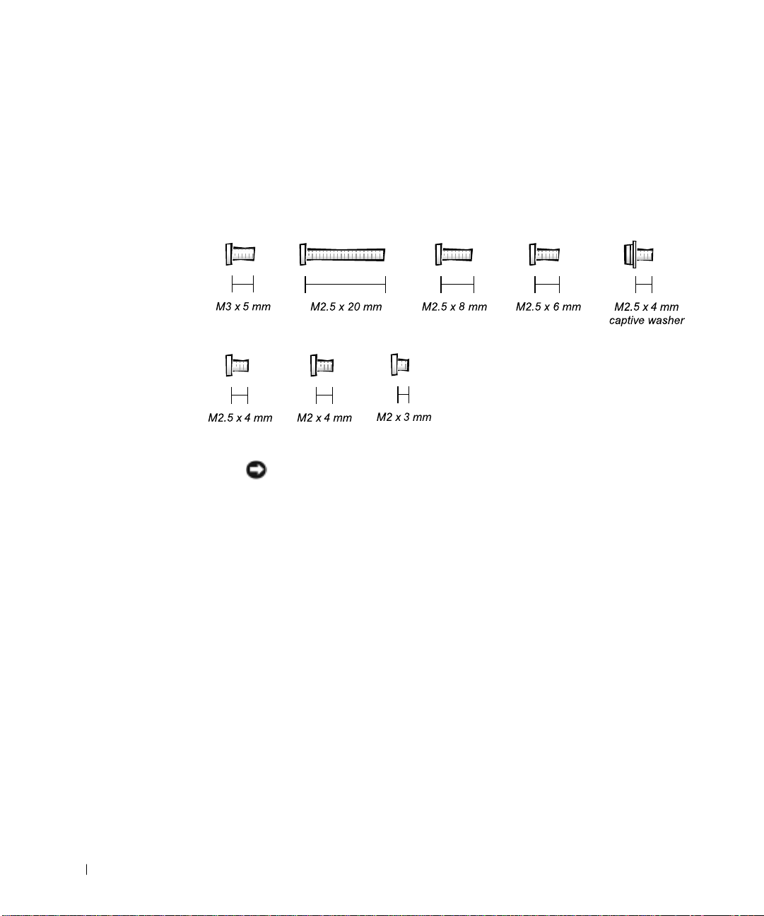
Screw Identification
When you are removing and replacing components, photocopy the
placemat as a tool to lay out and keep track of the component screws.The
placemat provides the number of screws and the sizes.
Screw Identification
www.dell.com | support.dell.com
NOTICE: When reinstalling a screw, you must use a screw of the correct
diameter and length. Make sure that the screw is properly aligned with its
corresponding hole, and avoid overtightening.
10 Before You Begin
Page 13
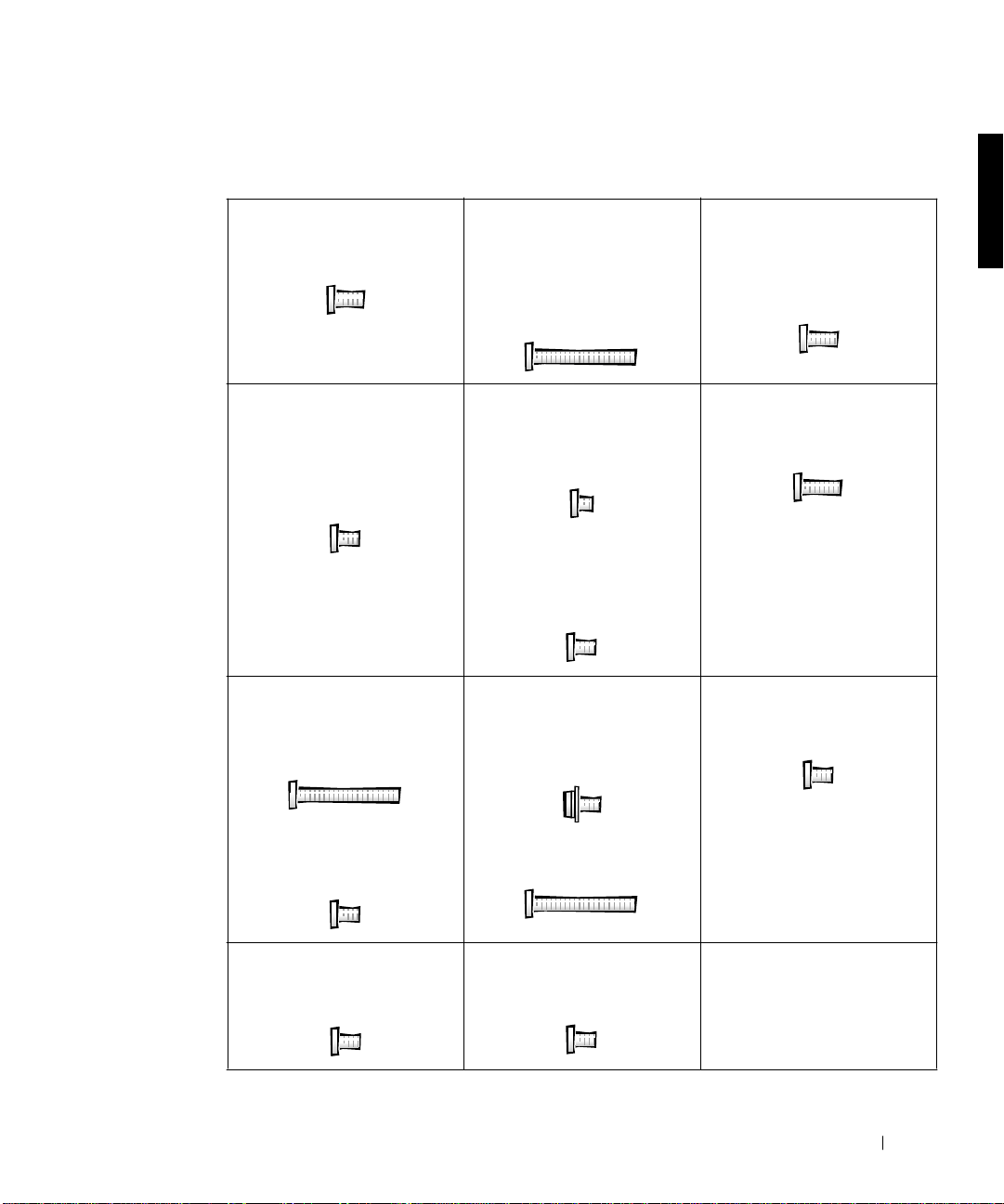
Screw Placement Map
Hard Drive Doo r Security:
M3.0 x 5 mm (1 each)
Display Bezel:
Rubber screw covers (4 each)
Plastic screw covers (2 each)
M2.5 x 4 mm (6 each)
Palmre st to
Bottom Case Assembly:
M2.5 x 20 mm (9 each)
Keyboar d to Bottom Cas e
Assembly:
M2.5 x 20 mm (4 each; one in
memory door and one in miniPCI door)
Display Panel to Disp l ay
Mounting Bracket:
M2.0 x 3 mm(6 each)
Fl ex C abl e Mo un ti ng B rack e t to
To p Co ver:
M2.5 x 4 mm (1 each)
System Board:
M2 .5 x 4 mm c aptive w a sh er
(3 each)
Display to Base:
M2.5 x 6 mm (3 each; 2 at back
of system; 1 at flex cable strai n
relief)
Video Graphics Board:
M2.5 x 8 (3 each)
LED B oa r d :
M2.0 x 4 mm (2 each)
Palmre st Bracke t:
M2.5 x 4 mm (2 each)
Fan Assembly :
M2.0 x 4 mm (3 each)
M2.5 x 20 mm (1 each)
RJ-11/RJ-45 Board Assembly:
M2.5 x 4 mm (1 each)
Before You Begin 11
Page 14

www.dell.com | support.dell.com
12 Before You Begin
Page 15
SECTION 2
Removing and Replacing Parts
System Components
Hard Drive
Fixed Optical Drive
Memory Module
2
Mini PCI Card Assembly
Keyboard Assembly
Display and Bezel Assemblies
Microprocessor Thermal Cooling Assembly
Microprocessor Module
Video Graphics Board
Palmrest Assembly
Reserve Battery
System Board Assembly
Battery and Modular Bay Latch Assemblies
Battery Charger Board
LED Board
Fan Assembly
RJ-11/RJ-45 Board
www.dell.com | support.dell.com
Page 16
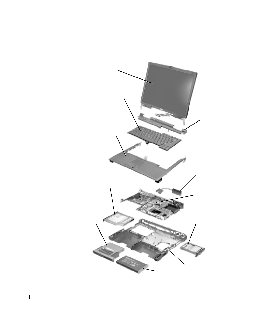
System Components
Exploded View
display
assembly
keyboard
www.dell.com | support.dell.com
hinge cover
palmrest
assembly
thermal cooling
assembly
fixed optical drive
system board
modular device
14 Removing and Replacing Parts
hard drive
bottom case assembly
main battery
Page 17
NOTICE: Only a certified service technician should perform repairs on your
computer . Damage due to servicing that is not authorized by Dell is not covered
by your warranty.
NOTICE: Unless otherwise noted, each procedure in this manual assumes that
a part can be replaced by performing the removal procedure in reverse order.
Hard Drive
NOTICE: Disconnect the computer and attached devices from the electrical
outlet and remove any installed batteries.
NOTICE: To avoid ESD, ground yourself by using a wrist grounding strap or
by periodically touching unpainted metal on the computer.
NOTICE: The hard drive is very sensitive to shock. Handle it by its edges (do
not squeeze the top of the case), and avoid dropping it.
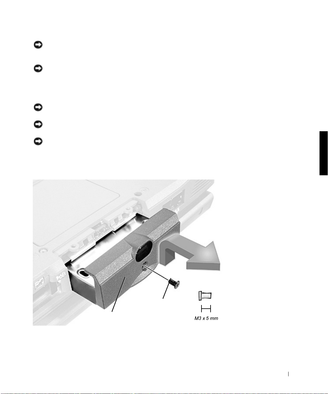
Hard Drive
bottom of computer
hard drive door
hard drive door
5-mm screw
Removing and Replacing Parts 15
Page 18
Removing the Hard Drive
1 Follow the instructions in “Preparing to Work Inside the Computer.”
2 Remove the drive door screw.
3 Pull the hard drive out.
Replacing the Hard Drive
1 Gently push the hard drive into the drive bay until the drive door is
flush with the computer case.
2 Push down on the drive until it snaps into place.
www.dell.com | support.dell.com
3 Replace the screw in the hard drive door.
Fixed Optical Drive
NOTICE: Disconnect the computer and attached devices from the electrical
outlet and remove any installed batteries.
NOTICE: To avoid ESD, ground yourself by using a wrist grounding strap or
by periodically touching unpainted metal on the computer.
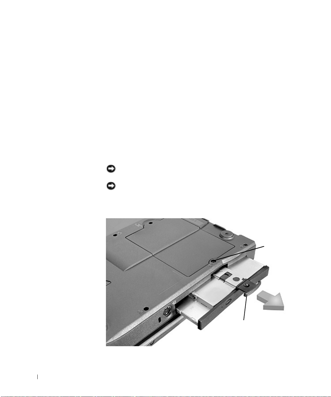
Fi xed Op tical Drive
16 Removing and Replacing Parts
captive
screw
pull tab
Page 19
Removing the Fixed Optical Drive
1 Follow the instructions in “Preparing to Work Inside the Computer.”
2 Loosen the captive screw on the bottom of the computer.
NOTICE: To keep the pull tab from catching on the captive screw, turn the
computer over before removing the fixed optical drive.
3
Turn the computer over, pull out the pull tab, and use the pull tab to
remove the fixed optical drive.
Memory Module
NOTICE: Disconnect the computer and any attached devices from electrical
outlets and remove any installed batteries.
NOTICE: To avoid ESD, ground yourself by using a wrist grounding strap or
by periodically touching unpainted metal on the computer.
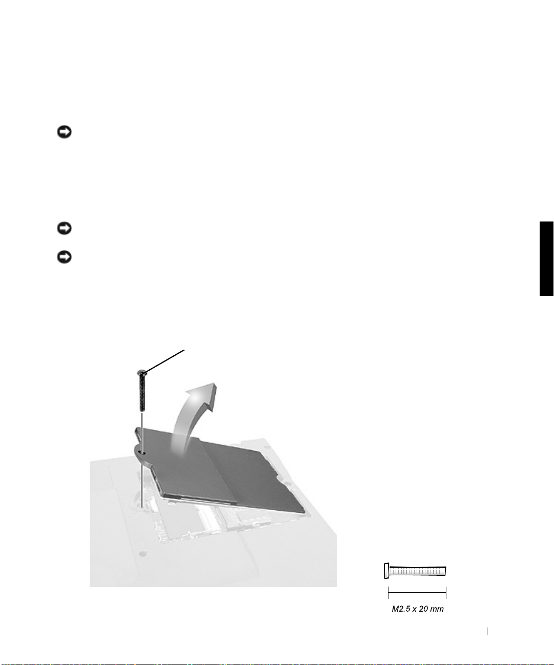
Removing the Memory Module Cover
Memory Module Cover
20-mm screw
Removing and Replacing Parts 17
Page 20

1 Follow the instructions in “Preparing to Work Inside the Computer.”
2 Remove the screw.
3 Disengage the metal tabs at the opposite end of the cover.
Memo ry Module s
DIMM B
www.dell.com | support.dell.com
tabs (2 per
socket)
memory
module sockets (2)
DIMM A
Removing the Memory Modules
1 Remove the memory module cover.
2 To release a memory module from its socket, spread apart the tabs at
each side of the module until the module pops up slightly.
3 Lift the memory module out of its socket.
Replacing the Memory Modules
1 If you only have one memory module, install it in the socket labeled
“DIMM A.” Install a second memory module in the socket labeled
“DIMM B.”
18 Removing and Replacing Parts
Page 21

NOTE: Memory modules are keyed to fit into their sockets in only one
direction.
Insert the memory module’s edge connector into the socket slot at a
2
45-degree angle and press the module firmly into the slot.
3 Pivot the module down until it clicks into place. If you do not hear a
click, remove the module and reinstall it.
4 Insert the metal tabs on the memory module cover into the bottom
case assembly, rotate the cover down, and replace the screw.
Mini PCI Card Assembly
You must remove the optional Mini PCI Card assembly before the system
board a ssembly can be remove d. A Mini PC I Card assembly ma y consist of a
modem, a NIC, a modem and NIC combination, or a wireless NIC. A
modem, NIC, or modem and NIC combination must be connected to the
wiring harness as appropriate; a wireless NIC must be connected to the
system’s internal antenna.
NOTICE: Disconnect the computer and attached devices from electrical
outlets and remove any installed batteries.
NOTICE: To avoid ESD, ground yourself by using a wrist grounding strap or
by periodically touching unpainted metal on the computer.
Removing and Replacing Parts 19
Page 22

Mini PCI Card Cover
20-mm screw
www.dell.com | support.dell.com
Removing the Mini PCI Card Assembly
1 Follow the instructions in “Preparing to Work Inside the Computer.”
2 Remove the Mini PCI Card cover.
3 To release the Mini PCI Card assembly, spread the metal securing tabs
until the assembly pops up slightly.
4 Disconnect the assembly from the wiring harness or internal antenna.
5 Lift out the assembly and disconnect any attached cables.
20 Removing and Replacing Parts
Page 23

Replacing the Mini PCI Card Assembly
1 Align the Mini PCI Card assembly with the socket at a 45-degree
angle, and press the Mini PCI Card into the socket.
2 Depending on what type of Mini PCI Card you are installing, either
connect the wiring harness to the Mini PCI Card assembly, or connect
the mini-coax antenna cable from the Mini PCI Card assembly to the
internal antenna.
NOTICE: The connectors are keyed for correct insertion; do not force the
connections.
Mini PCI Card Assembly Using Wiring Harness
wiring
harness
Removing and Replacing Parts 21
Page 24

Mini-PCI Wireless NIC Assembly Using Antenna Cable
connection to internal
system antenna
www.dell.com | support.dell.com
mini-coax
antenna cable
wiring harness
NOTICE: If a wireless NIC card contains two mini-coax antenna connectors,
connect the mini-coax antenna cable to the
the card as shown.
NOTICE: If you are installing a wireless NIC, fold and tuck the unused wiring
harness into the slot so it does not interfere with the cover.
3
Pivot the Mini PCI Card assembly down until it clicks into place.
4 Replace the Mini PCI Card assembly cover.
outermost
outermost
antenna connector
on card
antenna connector on
Keyboard Assembly
NOTICE: Disconnect the computer and attached devices from electrical
outlets and remove any installed batteries.
NOTICE: To avoid ESD, ground yourself by using a wrist grounding strap or
by periodically touching unpainted metal on the computer.
22 Removing and Replacing Parts
Page 25

Keyb oard Scre ws
20-mm screws (4)
Removing the Keyboard Assembly
1 Follow the instructions in “Preparing to Work Inside the Computer.”
2 Turn the computer over and remove the four screws labeled with a
“circle K.”
3 Turn the computer over and open the display.
NOTICE: Be careful when handling the keyboard. The keycaps are fragile,
easily dislodged, and time-consuming to replace.
4
Use a nonmarring tool under the blank key to pry up the keyboard.
Removing and Replacing Parts 23
Page 26

Keyboard Removal
scalloped edge
of blank key
keyboard
www.dell.com | support.dell.com
Lift the right end of the keyboard and slide it slightly toward the right
5
side of the computer to disengage the tabs at the left end.
6 Pivot the keyboard and balance it upright on the left side of the
computer.
24 Removing and Replacing Parts
right side of
computer
Page 27

Keyb oard Cabl e
keyboard cable
Disconnect the keyboard cable and lay the keyboard assembly aside.
7
Replacing the Keyboard Assembly
1 While bracing the keyboard assembly upright on its left end, connect
the keyboard cable to the interface connector on the system board.
NOTICE: Position the keyboard/track stick flex cable so it is not pinched
when you replace the keyboard in the bottom case assembly.
2
Insert the metal tabs at the left end of the keyboard under the edge of
the bottom case assembly, and fit the keyboard into place.
3 Check that the keyboard is correctly installed. The keys should be flush
with the left and right surfaces of the palmrest.
4 Reinstall the four screws in the holes labeled “circle K.”
Removing and Replacing Parts 25
Page 28

Display and Bezel Assemblies
NOTICE: Disconnect the computer and attached devices from electrical
outlets and remove any installed batteries.
NOTICE: To avoid ESD, ground yourself by using a wrist grounding strap or
by periodically touching unpainted metal on the computer.
Disp lay Assembly
www.dell.com | support.dell.com
display
display
flex cable
hinge cover
bottom case assembly
26 Removing and Replacing Parts
6-mm screws (3)
Page 29

Removing the Hinge Cover
Hinge Cover
hinge cover
Follow the instructions in “Preparing to Work Inside the Computer.”
1
2 Use a nonmarring tool to loosen the hinge cover at the back and at
each side of the computer.
3 Open the display and lift off the hinge cover.
Removing and Replacing Parts 27
Page 30

Removing the Display Assembly
Disp lay Assembly
www.dell.com | support.dell.com
Remove the hinge cover.
1
NOTICE: Make sure you remove the flex cable before you remove the display
assembly.
28 Removing and Replacing Parts
6-mm screws (2)
Page 31

Flex Cable
6-mm screw
pull loop
flex cable
strain relief
Remove the 6-mm screw that secures the display flex cable to the
2
strain relief, and then use the pull loop to remove the display flex cable
from the graphics card.
NOTICE: When reconnecting the flex cable, press down on both ends of the
connector, not in the middle. Pressing the middle of the connector can damage
fragile components.
3
Open the display and, from the back of the computer, remove the two
screws labeled with a “circle D” that secure the display assembly to the
bottom case assembly.
4 With the display in an upright position, lift the display assembly from
the bottom case assembly.
Removing and Replacing Parts 29
Page 32

Display Assembly Bezel and Panel
4-mm screws (6)
plastic screw
covers (2)
www.dell.com | support.dell.com
display panel
flex cable
hinge cover
rubber screw covers (4)
display assembly bezel
plastic
tabs (6)
4-mm
screw
flex cable
mounting
bracket
display
latch
Removing the D i splay Assembly Bezel
1 Use a scribe to pry out the four rubber screw covers located across the
top of the bezel.
30 Removing and Replacing Parts
top cover
3-mm screws (6)
Page 33

2 Remove the four 4-mm screws located across the top of the bezel.
3 Use a scribe at the indentations to pry out the two plastic screw covers
located at the bottom of the bezel.
4 Remove the two 4-mm screws located at the bottom of the bezel.
5 Separate the bezel from the display-assembly top cover.
The bezel is secured to the d isplay assembly top cover with plastic tabs
around the sides. Use a plastic scribe to help separate the bezel from
the top cover.
Removing the Display Panel
1 Remove the hinge cover.
2 Detach the display flex cable from the strain relief and the graphics
card.
3 Remove the display assembly bezel.
4 Remove the 4-mm screw securing the plastic flex cable mounting
bracket to the top cover assembly.
5 Remove the six 3-mm screws (three on each side) from the right and
left sides of the panel.
6 Lift the display panel and flex cable out of the top cover assembly.
7 Disconnect the flex cable from the two connectors (a ZIF and a
standard connector) on the display panel assembly.
Removing and Replacing Parts 31
Page 34

Flex Cable Connectors on Display Panel
ZIF connector
www.dell.com | support.dell.com
standard connector
Replacing the Display Panel
NOTE: Use a magnetic screwdriver to reassemble the display panel in the
display.
1
Connect the flex cable to the two connectors on the back of the
display panel.
2 Place the display panel assembly in the top cover, taking care that the
flex cable is in place and is not crushed or crimped.
32 Removing and Replacing Parts
Page 35

3 Reinstall the 4-mm screw that secures the flex cable mounting bracket
to the top cover.
4 Starting on the left side, use a magnetic screwdriver to reinstall the six
3-mm screws that secure the display panel in the top cover.
5 Reinstall the display flex cable strain-relief screw and reconnect the
flex cable to the graphics card.
6 Reinstall the display assembly bezel.
Removing the Display Latch
Removing the Display Latch
1
Remove the hinge cover.
2 Detach the display flex cable from the strain relief and the graphics
card.
3 Remove the display assembly bezel.
4 Remove the display panel from the top cover.
5 Remove the display latch by unsnapping the latch and captive spring.
Removing and Replacing Parts 33
Page 36

Microprocessor Thermal Cooling Assembly
NOTICE: Disconnect the computer and attached devices from electrical
outlets and remove any installed batteries.
NOTICE: To avoid ESD, ground yourself by using a wrist grounding strap or
by periodically touching unpainted metal on the computer.
Retaining Clip
www.dell.com | support.dell.com
microprocessor
retaining clip
microprocessor thermal
cooling assembly
Removing the Microprocessor Thermal Cooling Assembly
1 Follow the instructions in “Preparing to Work Inside the Computer.”
2 Remove the keyboard.
3 Remove the hinge cover.
34 Removing and Replacing Parts
Page 37

4 Insert a flat-blade screwdriver into the latc h mechanism at the left side
of the microprocessor retaining clip. Pry open the clip by pivoting the
top of the screwdriver toward the right side of the computer.
Microprocessor Thermal Cooling Assembly
microprocessor
thermal cooling
assembly
NOTICE: To ensure maximum cooling for the microprocessor, do not touch
the heat transfer areas on the microprocessor thermal cooling assembly. The
oils in your skin reduce the heat transfer capability of the thermal pads.
5
Lift out the thermal cooling assembly.
Microprocessor Module
NOTICE: Disconnect the computer and attached devices from electrical
outlets and remove any installed batteries.
NOTICE: To avoid ESD, ground yourself by using a wrist grounding strap or
by periodically touching unpainted metal on the computer.
Removing and Replacing Parts 35
Page 38

Microprocessor Module
www.dell.com | support.dell.com
Removing the Microprocessor Module
1 Follow the instructions in “Preparing to Work Inside the Computer.”
2 Remove the keyboard.
3 Remove the hinge cover.
NOTICE: To ensure maximum cooling for the microprocessor, do not touch
the heat transfer areas on the thermal cooling assembly. The oils in your skin
reduce the heat transfer capability of the thermal pads.
4
Remove the microprocessor thermal cooling assembly.
NOTICE: When removing the microprocessor module, pull the module
straight up. Do not bend the pins.
5
Remove the microprocessor module.
NOTICE: To avoid damage to the microprocessor, hold the screwdriver so that
it is perpendicular to the microprocessor when removing the cam lock screw
(see “Microprocessor Cam Lock Screw”).
a Loosen the microprocessor socket cam lock screw. The location of
36 Removing and Replacing Parts
the screw and the rotation direction may vary with the socket
manufacturer; look for small icons indicating open and locked
positions.
Page 39

Microprocessor Cam Lock Screw (Example)
NOTICE: Hold the microprocessor down while turning the cam lock screw to
prevent intermittent contact between the cam lock screw and microprocessor.
perpendicular
screwdriver
processor die
cam lock screw
b Use the microprocessor extraction tool to remove the
(do not touch)
microprocessor module.
Replacing the Microprocessor Module
NOTICE: If you received a flash BIOS update program diskette or CD with
the replacement microprocessor, you must update the BIOS after replacing the
microprocessor module. For instructions on updating or reflashing the BIOS,
see the
Dell Portable Computer BIOS Update Guide
NOTICE: Proper seating of the microprocessor module does not require force.
NOTICE: A microprocessor module that is not properly seated can result in
an intermittent connection and subsequent failures.
1
Align the pin-1 triangle on the microprocessor toward the pin-1
triangle in the socket, insert the microprocessor into the socket, and
move it around slightly until you feel it settle into the socket.
When the microprocessor module is correctly seated, all four corners
are aligned to the same height. If one or more corners of the module
are higher than the others, the module is not seated correctly.
.
Removing and Replacing Parts 37
Page 40

NOTICE: Hold the microprocessor down while turning the cam lock screw to
prevent intermittent contact between the cam lock screw and microprocessor
(see “Microprocessor Cam Lock Screw”).
Tighten the cam lock screw.
2
NOTICE: Do not over- or undertighten the screw. Tighten it until the screw
indicator points to the “closed” or “locked” indicator on the socket.
3
Replace the microprocessor thermal cooling assembly.
Closing the Microprocessor Retaining Clip
www.dell.com | support.dell.com
4
While pressing lightly down on the center of the retaining clip, insert a
flat-blade screwdriver into the latch mechanism and pivot the top of
the screwdriver away from the clip to close the latch.
Video Graphics Board
NOTICE: Disconnect the computer and attached devices from electrical
outlets and remove any installed batteries.
38 Removing and Replacing Parts
Page 41

NOTICE: To avoid ESD, ground yourself by using a wrist grounding strap or
by periodically touching unpainted metal on the computer.
Video Graphics Board
8-mm screws (3)
Removing the Video Graphics Board
1 Follow the instructions in “Preparing to Work Inside the Computer.”
2 Remove the keyboard.
3 Remove the hinge cover.
4 Detach the display flex cable from the strain relief and the graphics
card.
5 Remove the three 8-mm screws that secure the video graphics board.
6 Separate the video graphics board from the system board connector.
Replacing the Video Graphics Board
1 Align the three screw holes and press down firmly on the word “Dell”
to seat the board in its connector.
Removing and Replacing Parts 39
Page 42

NOTICE: Make sure the board is correctly and firmly seated before
continuing. Failure to do so will cause intermittent video failures.
Replace the three screws.
2
Palmrest Assembly
NOTICE: Disconnect the computer and attached devices from electrical
outlets and remove any installed batteries.
NOTICE: To avoid ESD, ground yourself by using a wrist grounding strap or
by periodically touching unpainted metal on the computer.
www.dell.com | support.dell.com
Palmrest Assembly
pull loop
NOTICE: The reserve battery provides power to the computer’s time RTC and
NVRAM when the computer is turned off. Removing the palmrest disconnects
the reserve battery and causes the computer to lose the date and time
information as well as all user-specified parameters in NVRAM. If possible,
make a copy of this information before you disconnect the reserve battery.
40 Removing and Replacing Parts
Page 43

Removing the Palmrest Assembly
1 Follow the instructions in “Preparing to Work Inside the Computer.”
2 Remove the hard drive and the fixed optical drive.
3 Remove the keyboard.
4 Remove the hinge cover.
5 Remove the display assembly.
NOTICE: To avoid damaging the palmrest assembly, you must first remove
the display assembly.
6
Turn the computer over.
7 Remove the nine 20-mm screws (labeled with a “circle P”) that secure
the palmrest to the computer.
Palmrest Screws
20-mm screw (9)
Removing and Replacing Parts 41
Page 44

8 Turn the computer over.
9 Use the pull loop to disconnect the palmrest flex cable from the touch-
pad connector on the system board.
10 Carefully lift out the palmrest assembly.
Reserve Battery
NOTICE: Disconnect the computer and attached devices from electrical
outlets and remove any installed batteries.
NOTICE: To avoid ESD, ground yourself by using a wrist grounding strap or
www.dell.com | support.dell.com
by periodically touching unpainted metal on the computer.
Reserve Battery
reserve battery cable
NOTICE: The reserve battery provides power to the computer’s RTC and
NVRAM when the computer is turned off. Removing the battery causes the
computer to lose the date and time information as well as all user-specified
parameters in NVRAM. If possible, make a copy of this information before you
remove the reserve battery.
42 Removing and Replacing Parts
reserve battery
palmrest bracket
Page 45

Removing the Reserve Battery
1 Follow the instructions in “Preparing to Work Inside the Computer.”
2 Remove the keyboard.
3 Remove the hinge cover.
4 Remove the display assembly.
5 Remove the palmrest assembly.
6 On the underside of the palmrest, disconnect the flex cable from the
ZIF connector.
Palmrest Flex Cable and Bracket
4-mm screw (2)
palmrest bracket
palmrest flex cable
7
Remove the two 4-mm screws securing the palmrest bracket.
8 While sup porting the palmrest flex cable, lift out the palmrest bracket
and turn it over.
9 Disconnect the reserve battery cable.
10 Remove the reserve battery:
a Pry the reserve battery free from the metal palmrest bracket.
b Remove the foam-pad remnants from the palmrest bracket.
Removing and Replacing Parts 43
Page 46

Replacing the Reserve Battery
1 Seat the reserve battery and press it into place.
2 Connect the reserve battery cable.
3 Place the palmrest bracket loosely in the palmrest, and connect the
palmrest flex cable to the ZIF connector.
4 Replace the two 4-mm screws that secure the palmrest bracket to the
palmrest.
System Board Assembly
www.dell.com | support.dell.com
NOTICE: Disconnect the computer and attached devices from electrical
outlets and remove any installed batteries.
NOTICE: To avoid ESD, ground yourself by using a wrist grounding strap or
by periodically touching unpainted metal on the computer.
System Board Screws
4-mm captivewasher screws (3)
20-mm screw
system board assembly
bottom case assembly
44 Removing and Replacing Parts
Page 47

The system board’s BIOS chip contains the system service tag number,
which is also visible on a bar-code label on the bottom of the computer.
Removing and Replacing Parts 45
Page 48

The replacement kit for the system board assembly includes a diskette or
CD that provides a utility for transferring the service tag number to the
replacement system board assembly.
NOTICE: If you received a flash BIOS update program diskette or CD with
the replacement microprocessor, you must update the BIOS after replacing the
microprocessor module. For instructions on updating or reflashing the BIOS,
see the
Dell Portable Computer BIOS Update Guide
.
Removing the S ystem Board
1 Follow the instructions in “Preparing to Work Inside the Computer.”
www.dell.com | support.dell.com
2 Remove the hard drive and the fixed optical drive.
3 Remove any installed Mini PCI Cards.
4 If migrating the memory, remove all installed memory modules.
5 Remove the keyboard.
6 Remove the hinge cover.
7 Remove the display assembly.
8 Remove the palmrest assembly.
9 Remove the video graphics board.
10 Remove the microprocessor thermal cooling assembly.
11 If migrating the microprocessor, remove the microprocessor module.
12 Remove the three 4-mm captive-washer screws from the system board.
13 Remove the 20-mm screw from the center of the LED board.
14 Lift the front of the system board and work it out of the back panel.
46 Removing and Replacing Parts
Page 49

System Board
Battery and Modular Bay Latch Assemblies
NOTICE: Disconnect the computer and attached devices from electrical
outlets and remove any installed batteries.
NOTICE: To avoid ESD, ground yourself by using a wrist grounding strap or
by periodically touching unpainted metal on the computer.
Removing and Replacing Parts 47
Page 50

Battery and Modular Bay Latch Assemblies
bumps
slider
www.dell.com | support.dell.com
location of
snap tabs (2)
latch buttons (2)
wear ribs
(2 on underside)
spring
bottom case assembly
Removing and Replacing the Battery and Modul ar Bay Latch Assemblies
1 Follow the instructions in “Preparing to Work Inside the Computer.”
2 Remove the keyboard.
3 Remove the hinge cover.
4 Remove the display assembly.
5 Remove the palmrest assembly.
48 Removing and Replacing Parts
Page 51

6 Remove a latch button from the bottom case assembly by squeezing
the snap tabs in the center of the latch.
Apply downward pressure to the tabs while squeezing them together
(tweezers work well) to eject the latch button from the bottom of the
case without loosening the upper latch assembly (spring and slider). If
the upper latch assembly does come loose:
a Reinsert the spring onto the slider, and reinstall both pieces in the
latch housing on the inside of the case.
b Ensure that the slider is inserted so that the side with the two
bumps is facing the back of the case, and t he surfa ce with the wear
ribs is facing the bottom of the case.
7 Hold the upper latch assembly in place while you snap the new latch
button in from underneath the base, making certain the snap tabs are
fully engaged in the slider.
8 Ensure that the newly installed latch assembly moves smoothly and
freely when pushed and released.
Battery Charger Board
NOTICE: Disconnect the computer and attached devices from electrical
outlets and remove any installed batteries.
NOTICE: To avoid ESD, ground yourself by using a wrist grounding strap or
by periodically touching unpainted metal on the computer.
Removing and Replacing Parts 49
Page 52

Battery Charger Board
www.dell.com | support.dell.com
Removing the Battery Charger Board
1 Follow the instructions in “Preparing to Work Inside the Computer.”
2 Remove the keyboard.
3 Remove the hinge cover.
4 Remove the display assembly.
5 Remove the palmrest assembly.
6 Remove the video graphics board.
7 Lift the battery charger board out of the system board connector.
Replacing the Battery Charger Board
Align the screw holes on the battery charger board with the screw holes on
the bottom case assembly (see Battery Charger Board), and then press the
battery charger board down into its connector.
50 Removing and Replacing Parts
Page 53

LED Board
NOTICE: Disconnect the computer and attached devices from electrical
outlets and remove any installed batteries.
NOTICE: To avoid ESD, ground yourself by using a wrist grounding strap or
by periodically touching unpainted metal on the computer.
LED Board
4-mm screws (2)
Removing the LED Board
1 Follow the instructions in “Preparing to Work Inside the Computer.”
2 Remove the hinge cover.
3 Remove the two 4-mm screws.
4 Lift the LED board away from its connector.
Removing and Replacing Parts 51
Page 54

Replacing the LED Board
1 Align the two screw holes with the two mounting holes on the bottom
case assembly, and press the board into its connector.
2 Replace the two 4-mm screws.
Fan Assembly
NOTICE: Disconnect the computer and attached devices from electrical
outlets and remove any installed batteries.
NOTICE: To avoid ESD, ground yourself by using a wrist grounding strap or
www.dell.com | support.dell.com
by periodically touching unpainted metal on the computer.
Fan Assem bly
fan cables
4-mm screws (3)
Removing the Fan Assembly
1 Follow the instructions in “Preparing to Work Inside the Computer.”
2 Remove the system board.
3 Remove the three 4-mm screws from the fan assembly.
4 Disconnect the two fan cables from the system board.
52 Removing and Replacing Parts
Page 55

5 Pull the fan assembly away from the back-panel bracket.
NOTICE: When reconnecting the fan cables, connect the shorter cable to the
connector closest to the fan assembly. R oute both cables so that they will not be
pinched by the thermal cooling assembly.
RJ-11/RJ-45 Board
NOTICE: Disconnect the computer and attached devices from electrical
outlets and remove any installed batteries.
NOTICE: To avoid ESD, ground yourself by using a wrist grounding strap or
by periodically touching unpainted metal on the computer.
RJ-11 and RJ-45 Connector Covers
connector covers (2)
Removing the Protective Covers Fr om t he RJ-11 and RJ-45 Connectors
Remove a plastic connector cover (if necessary) by slipping a nonmarring
tool into the cutout at the top and pivoting the tool up to disengage the
inner securing tab.
Removing and Replacing Parts 53
Page 56

T o replace a connector cover , orient the cover notch-side- up and snap i t into
the connector cutout.
RJ-11/RJ-45 Board
4-mm screw
www.dell.com | support.dell.com
Removing the RJ-11/R J-45 Boar d
1 Follow the instructions in “Preparing to Work Inside the Computer.”
2 Remove the system board.
3 Remove the 4-mm screw from the RJ-11/RJ-45 board.
NOTICE: The plastic tab is fragile; pull it back only far enough to remove the
board assembly.
4
Reach into the enclosure and, while pulling the tall plastic tab away
from the board assembly to release it, lift out the assembly.
When replacing the RJ-11/RJ-45 board assembly, protect the wiring harness
by routing it between the plastic posts.
54 Removing and Replacing Parts
Page 57

RJ-11/RJ-45 Board Harness Routing
posts
Removing and Replacing Parts 55
Page 58

www.dell.com | support.dell.com
56 Removing and Replacing Parts
Page 59

Index
B
battery charger board
removing, 50
replacing, 50
D
display and bezel assemblies
(illustrated), 26
display assembly, 28
bezel, removal, 30
display assembly bezel, 30
display assembly bezel and
panel (illustrated), 30
display flex cable, 29, 32
display latch, 33
display panel
removing, 31
replacing, 32
F
fan assembly, 52
fixed optical drive, 16
flex cable
display, 29, 32
palmrest, 43
H
hard drive
removing, 16
replacing, 16
hinge cover, 27
K
keyboard assembly
removing, 23
replacing, 25
L
latch assemblies, battery and
modular bay, 47
LED board
removing, 51
replacing, 52
M
memory module
removing modules , 18
removing the cover, 17
replacing modules, 18
microprocessor module
removing, 36
replacing, 37
microprocessor thermal
cooling assembly, 34
mini-PCI card assembly
removing, 20
replacing, 21
P
palmrest assembly, 40
palmrest flex cable, 43
preparing to work inside the
computer, 8
R
reserve battery
removing, 43
replacing, 44
RJ-11 and RJ-45 board
assembly
removing and replacing , 54
removing the covers, 53
S
screws
identification, 10
placement map, 11
system board assembly, 44
system components, 14
Index 57
Page 60

58 Index
T
tools, recommended, 9
V
video graphics board
removing, 39
replacing, 39
58 Index
Page 61

Page 62

064MCW A01
P/N 64MCW Rev. A01
Printed in the U.S.A.
www .dell.com
support.dell.com
 Loading...