

Page 1
S/5
Datex-Ohmeda
TM
Light Monitor, F-LM1, F-LMP1
Technical Reference Manual
CAUTION: U.S. Federal law restricts this device to sale by or on the order of a licensed medical practitioner.
Datex-Ohmeda, Inc.
P.O. Box 7550
Madison, WI 53707-7550, USA
Tel. +1-608-221-1551
Fax +1-608-222-9147
All specifications are subject to change without notice.
Outside the USA, check local laws for any restriction that may apply.
Order Code M1037863
October 2005
Healthcare Finland Oy
Helsinki, Finland
P.O. Box 900
FIN-00031 GE, FINLAND
Tel: +358 10 39411
Fax : +358 9 146 3310
www.datex-ohmeda.com www.gehealthcare.com
© 2005 Copyright General Electric Company
Page 2

Intended purpose
Datex-Ohmeda S/5 Light Monitor, F-LM1, F-LMP1 is intended for stationary and mobile monitoring of
patient’s ECG, SpO2, body temperature, invasive and non-invasive blood pressures as well as respiration
and CO2 in hospitals and ambulances. When used outdoors, the monitor must be in the protective case. The
monitor is intended for use by qualified medical personnel only. The S/5 Light Monitor is intended for
patients with weight from 5 kg (11 lb.) up. Respiration monitoring is intended for patients three years old and
up.
Classification according to IEC 60601-1
• CLASS I EQUIPMENT and INTERNALLY POWERED EQUIPMENT according to the type of protection against
electrical shock.
• TYPE BF or CF equipment according to the degree of protection against electric shock is indicated with a
symbol beside each patient connector.
• Degree of protection against harmful ingress of water as detailed in the IEC 60529: Monitor: IPX1,
vertically falling water drops shall have no harmful effects (applicable when the monitor is in upright
position, or tilted backwards). In the protective case IPX4, splash proof, when the case is closed
properly, the monitor is intact and operates on battery power. Power adapter: IPX0, ordinary equipment.
• EQUIPMENT not suitable for use in the presence of a FLAMMABLE ANESTHETIC MIXTURE with air or with
oxygen or nitrous oxide.
• CONTINUOUS OPERATION according to the mode of operation.
• CSPR 11: Group 1, Class A
Classification according to EU Medical Device Directive
• The monitor is classified as IIb.
Responsibility of the manufacturer
GE Healthcare Finland Oy (GE) is responsible for the safety, reliability and performance of the equipment only
if:
• assembly, operations, extensions, readjustments, modifications, service and repairs are carried out by
authorized personnel.
• the electrical installation of the relevant room complies with appropriate requirements.
• the equipment is used in accordance with the User’s Reference Manual and serviced and maintained in
accordance with the Technical Reference Manual.
The CO2 measuring option (N-LCM) is manufactured for GE Healthcare Finland Oy by
Welch Allyn OEM Technologies, 8500 SW Creekside Place, Beaverton, OR 97008 USA.
Trademarks
Trademarks Datex, Ohmeda, S/5, MemCard, ComWheel and Oxytip+ are property of GE Healthcare Finland
Oy. All other product and company names are property of their respective owners.
Page 3

Master table of contents
Datex-Ohmeda S/5TM Light Monitor
Technical Reference Manual, M1037863
PART I, General Service Guide
Document
No.
M1051339
8001934-2
M1051339
8000060-1
8000060-1
8000060-1
8000060-1
890201-5
M1051340
890200-5
896192-1
8000060-1
M1051358
896551-2
896552-2
896553-2
896554-2
-
Updated Updated
Description
Introduction, Safety, Architecture, Functional check, Service check, General
troubleshooting, Service Menu, General specifications
Planned Maintenance Instructions
PART II, Product Service Guide
CPU
Power Supply Unit
Hemodynamic Unit
CO2 Unit
Isolation Power Supply Unit for CO2 Unit
Datex-Ohmeda Light Monitor Recorder, N-LREC
Datex-Ohmeda Light Monitor Power Adapter, N-LPOW
Datex-Ohmeda Light Monitor Battery Module, F-LBAT
Datex-Ohmeda Light External Battery Charger, N-LCHGR
DataCard and Network Options, N-LDATA, N-LNET, N-LDNET
Spare Parts, Upgrade Kits and Exploded Views
Optional N-LCM Upgrade for Light Monitor
Optional N-LDNET Upgrade for Light Monitor
Optional N-LDATA Upgrade for Light Monitor
Optional N-LNET Upgrade for Light Monitor
Method of Replacing the Lamp Unit (LCD Backlight)
1
2
1
2
3
4
5
6
7
8
9
10
11
12
Document No. M1037863
Page 4

Datex-Ohmeda S/5 Light Monitor
2
Document No. M1037863
Page 5

Table of contents
TABLE OF CONTENTS
PART 1 - GENERAL SERVICE GUIDE
TABLE OF CONTENTS i
Part 1 - General Service Guide i
TABLE OF FIGURES iii
1 INTRODUCTION 1
1.1 Notes to the reader............................................................................................................................... 2
1.2 About this manual................................................................................................................................ 2
1.3 Related documents .............................................................................................................................. 2
1.4 Installation .......................................................................................................................................... 3
1.4.1 Choosing the location .................................................................................................................. 3
1.4.2 Warnings.....................................................................................................................................3
1.5 Symbols .............................................................................................................................................. 4
1.5.1 Symbols on equipment ................................................................................................................ 4
1.5.2 Symbols on transport packaging................................................................................................... 6
2 SAFETY 8
2.1 Safety precautions ...............................................................................................................................8
2.1.1 Warnings.....................................................................................................................................8
2.1.2 Cautions....................................................................................................................................11
2.2 ESD precautionary procedures............................................................................................................ 12
2.3 Safety test ......................................................................................................................................... 13
3 ARCHITECTURE 14
3.1 Monitor structure................................................................................................................................ 14
3.2 Power supply unit...............................................................................................................................16
3.3 CPU...................................................................................................................................................16
3.4 NIBP unit ...........................................................................................................................................17
3.5 ECG unit ............................................................................................................................................ 17
3.6 STP unit .............................................................................................................................................17
3.7 CO2 unit............................................................................................................................................. 17
3.8 Display unit........................................................................................................................................ 18
3.8.1 Slave display.............................................................................................................................18
3.9 Power adapters..................................................................................................................................18
3.9.1 N-LPOW..................................................................................................................................... 18
3.10 Host serial communications ...........................................................................................................18
3.10.1 Module bus ........................................................................................................................... 18
3.10.2 Computer interface (RS-232) ................................................................................................. 18
3.10.3 CO2 module........................................................................................................................... 19
3.10.4 Power board .......................................................................................................................... 19
3.10.5 Recorder ...............................................................................................................................19
4 CLEANING 20
5 FUNCTIONAL CHECK 21
5.1 General functional inspection .............................................................................................................21
5.1.1 Recorder test.............................................................................................................................23
5.1.2 PCMCIA card test.......................................................................................................................23
5.1.3 Network test .............................................................................................................................. 24
Document No. M1051339
i
Page 6

Datex-Ohmeda S/5 Light Monitor
ECG board tests......................................................................................................................... 25
5.1.4
5.1.5 STP board tests ......................................................................................................................... 25
5.1.6 NIBP board test ......................................................................................................................... 26
5.1.7 Mainstream CO2 test.................................................................................................................. 26
5.2 Performance checks........................................................................................................................... 27
6 SERVICE CHECK 30
6.1 General service information................................................................................................................ 30
6.2 Service check procedure .................................................................................................................... 30
6.2.1 Visual inspection ....................................................................................................................... 31
6.2.2 Recorder test............................................................................................................................. 35
6.2.3 PCMCIA card test....................................................................................................................... 35
6.2.4 Network test.............................................................................................................................. 35
6.2.5 ECG measurement..................................................................................................................... 36
6.2.6 Respiration measurement.......................................................................................................... 37
6.2.7 Temperature measurement ........................................................................................................ 39
6.2.8 Invasive blood pressure measurement........................................................................................ 39
6.2.9 SpO2 measurement ................................................................................................................... 40
6.2.10 Non Invasive Blood Pressure measurement ............................................................................ 41
6.2.11 Mainstream CO2 measurement .............................................................................................. 43
6.2.12 For Light Monitor.................................................................................................................... 44
7 ADJUSTMENTS AND CALIBRATIONS 45
7.1 Pressure safety level detection “OFFSET”............................................................................................. 45
7.2 NIBP calibrations ............................................................................................................................... 45
7.2.1 Calibration check....................................................................................................................... 45
7.2.2 Calibration ................................................................................................................................ 46
7.3 Temperature calibration ..................................................................................................................... 47
7.4 Invasive pressure calibration .............................................................................................................. 48
8 GENERAL TROUBLESHOOTING 49
8.1 Troubleshooting flowchart .................................................................................................................. 49
9 SERVICE MENU 50
9.1 SW version / unit ID ........................................................................................................................... 50
9.2 Language selection ............................................................................................................................ 51
9.3 Monitor configuration......................................................................................................................... 51
10 GENERAL SPECIFICATIONS 52
10.1 Parameter specifications................................................................................................................ 52
10.1.1 ECG ...................................................................................................................................... 52
10.1.2 Impedance respiration...........................................................................................................52
10.1.3 Pulse oximetry (SpO2)/Pleth.................................................................................................. 53
10.1.4 Temperature.......................................................................................................................... 53
10.1.5 Non-invasive blood pressure.................................................................................................. 54
10.1.6 Invasive blood pressure (LMP1 models only)........................................................................... 54
10.1.7 CO2 (option N-LCM) ............................................................................................................... 55
10.2 General ......................................................................................................................................... 55
10.2.1 Environmental conditions ...................................................................................................... 56
10.3 Option codes ................................................................................................................................. 56
10.4 Display .......................................................................................................................................... 56
10.4.1 Slave display......................................................................................................................... 56
10.4.2 Trends................................................................................................................................... 57
10.4.3 Alarms .................................................................................................................................. 57
10.5 Light Monitor battery module (optional) (w/2 battery slots) .............................................................. 57
10.6 Light Monitor backup battery (optional)........................................................................................... 57
ii
Document No. M1051339
Page 7

Table of contents
External power adapter...................................................................................................................57
10.7
10.8 Light External Battery Charger (optional) .......................................................................................... 58
10.9 Output specifications .....................................................................................................................58
10.9.1 Nurse Call and Defibrillator Synchronization Signals ................................................................ 58
APPENDICES 59
FUNCTIONAL CHECK form A-1
SERVICE CHECK form B-1
EMC Guidance C-1
TABLE OF FIGURES
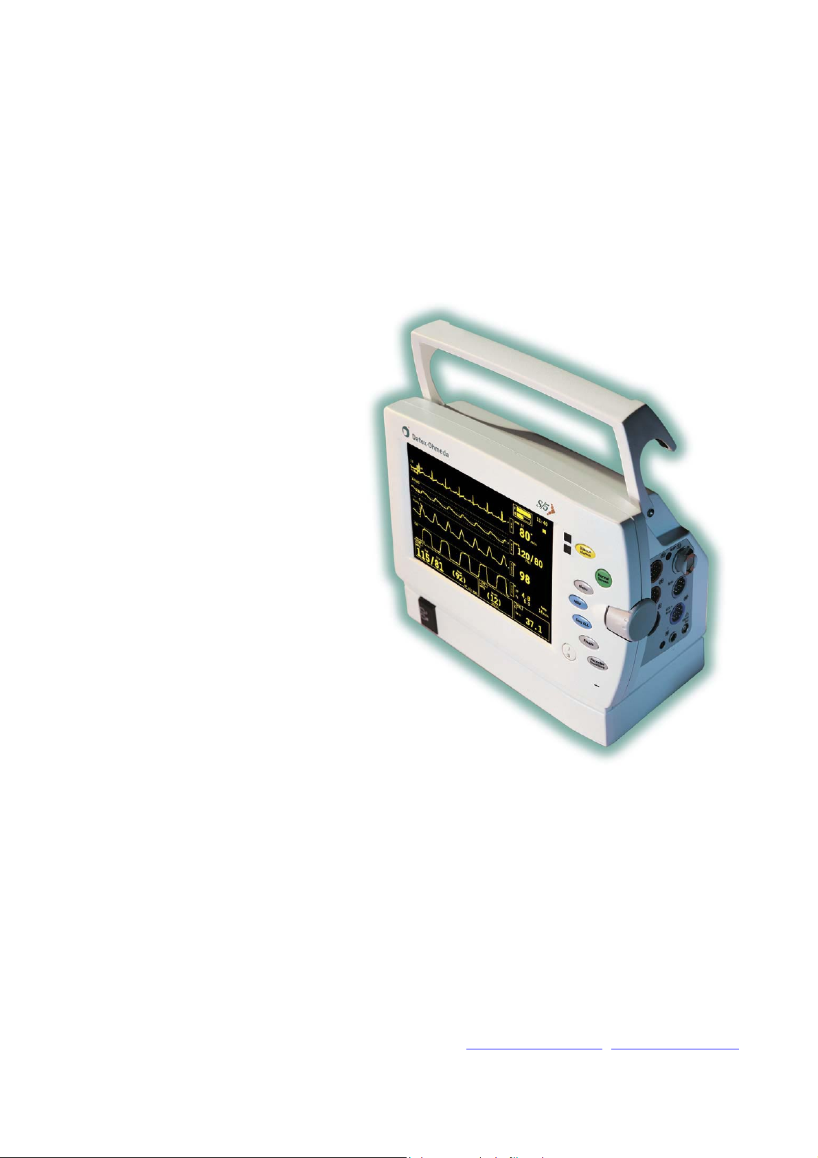
Figure 1 S/5 Light Monitor with battery module and power adapter ..................................................................... 1
Figure 2 Main block diagram of Light Monitor, revision 03 .................................................................................14
Figure 3 General troubleshooting chart............................................................................................................. 49
Document No. M1051339
iii
Page 8

Datex-Ohmeda S/5 Light Monitor
v
i
Document No. M1051339
Page 9

1 INTRODUCTION
The S/5 Light Monitor is a portable factory configurated compact monitor designed for stationary
and mobile indoor monitoring of a patient’s vital signs. The monitor is available in two
configurations; F-LM1 and F-LMP1. The difference between the configurations is illustrated in
table 1. Additionally, the monitor can be equipped with an optional recorder and battery module.
An external power adapter is provided for power supply. The Light Monitor has also data card
option and Ethernet interface which enables connecting the monitor to the network for remote
monitoring the patient and data collection.
Introduction
l
ll
Figure 1 S/5 Light Monitor with battery module and power adapter
Table 1 Basic parameter configurations
ECGR NIBP SpO2 TEMP InvBP
F-LM1
F-LMP1
1)
number of channels
• • •
• • •
Parameters
1)
1
1)
1
-
1)
2
Parameter explanations:
ECGR ECG and respiration
NIBP Non-invasive blood pressure
Pulse oximetry
SpO
2
TEMP Temperature
InvBP Invasive blood pressure
Document No. M1051339
1
Page 10

Datex-Ohmeda S/5 Light Monitor
The following factory configurable parameters and functions are available:
• N-LNET; Network option
• N-LDATA; DataCard option
• N- LDNET; Network and DataCard options
• N-LCM; Mainstream CO
To all monitors following options are available:
• N-LREC; Thermal printer
• N-LPOW; External power supply, input: 110/230 VAC
• F-LBAT; Battery Module w/ two batteries
• N-LCHGR; External battery charger w/ two batteries
• N-LBB; Rechargeable built-in backup battery
1.1 Notes to the reader
GE Healthcare reserves the right to make changes in product specifications without prior notice.
The information in this manual is believed to be accurate and reliable; however, the manufacturer
assumes no responsibility for its use.
GE Healthcare assumes no responsibility for the use or reliability of its software on equipment that
is not furnished by GE Healthcare.
1.2 About this manual
This technical reference manual is intended for service personnel who will perform service and
maintenance procedures on the Light Monitor.
option
2
This technical reference manual is divided into two parts:
• Part I contains a general description of the monitor and service procedures.
• Part II contains detailed descriptions of the component parts of the monitor.
1.3 Related documents
S/5 Light Monitor User's Reference Manual
The User’s Reference Manual provides detailed instructions and references for the operation and
configuration of the monitor. Everyday service, maintenance procedures and troubleshooting hints
are also included.
Patient Monitor Supplies and Accessories
The Patient Monitor Supplies and Accessories Catalogue provides information on all supplies and
accessories available for the monitor.
2
Document No. M1051339
Page 11

Introduction
1.4 Installation
1.4.1 Choosing the location
The monitor can be placed on a flat surface or hung with the handle from the bed or wall rails. Make
sure that the surface or rail holds up to at least 10 kg/22 lb.
1.4.2 Warnings
WARNING The monitor or its components should not be used adjacent to or stacked with
other equipment. If adjacent or stacked use is necessary, the monitor and its
components should be observed to verify normal operation in the configuration
in which it will be used.
When choosing the location, refer to the appendix C later in this document.
Document No. M1051339
3
Page 12

Datex-Ohmeda S/5 Light Monitor
1.5 Symbols
1.5.1 Symbols on equipment
on the rear panel
indicates the
warning:
Attention, consult accompanying documents.
Electric shock hazard. Do not open monitor frame. Refer servicing to qualified personnel.
Do not touch any part of monitor or patient connections during defibrillation procedure.
Disconnect power supply before servicing. Use only external power adapter N-LPOW.
on the rear panel dust
filter indicates the
reminder:
on the patient
connector panel
indicates the
cautions:
on the external power
adapter indicates the
cautions:
on the battery unit
indicates the
warnings and
cautions:
on the CPU board
indicates the caution:
Check rear panel dust filter regularly, and clean at least once a month.
Use only the specified cables and accessories.
Ensure proper contact of the return electrode of the electrosurgery unit to your patient to
avoid possible burns at ECG electrode or other probe sites.
For continued protection against fire hazard, replace only with same type and rating of fuse.
Make sure voltage selector is set according to local voltage.
For indoor use only. For patient transport outdoors use the monitor in protective case and
battery powered.
Do not immerse in liquid or allow any liquid to enter the interior.
Do not put in fire.
Do not short-circuit any terminals.
Do not disassemble or mutilate.
Use only with Battery Module or External Battery Charger.
Discharge and charge batteries fully every 3 months or more often, if required, to restore full
capacity.
Sealed NiCd battery must be recycled or disposed of properly. Discharge before disposing.
There is a lithium battery on the CPU board. Discard useless battery according to local
regulations.
on the CO
4
Document No. M1051339
sensor Do not immerse the sensor in liquids or autoclave it.
2
Page 13
Introduction
d
SpO
: Type BF (IEC-60601-1) protection against electrical shock, not defibrillation proof.
2
: Type CF (IEC-60601-1) protection against electrical shock, not defibrillation proof.
T
1
NIBP: Type BF (IEC-60601-1) defibrillator-proof protection against electrical shock.
ECG, P
, P2: Type CF (IEC-60601-1) defibrillator-proof protection against electrical shock.
1
Battery packs contain heavy metal cadmium (chemical symbol Cd) and, in case of
disposal, must be separated from other waste according to local regulations.
Ni-Cd
Ni-C
This symbol indicates that the waste of electrical and electronic equipment must not be
disposed as unsorted municipal waste and must be collected separately. Please contact
an authorized representative of the manufacturer for information concerning the
decommissioning of your equipment.
Battery packs contain Ni-Cd and they can be recycled.
Protective earth terminal
Input voltage
Output voltage
Power ON/STANDBY
IPX-class:
IPX0
Alternating current
Direct current
Degree of protection against harmful ingress of water as detailed in the IEC 60529:
– ordinary equipment
Document No. M1051339
5
Page 14

Datex-Ohmeda S/5 Light Monitor
IPX1
IPX4
– vertically falling water drops shall have no harmful effects.
– splash proof
SN, S/N Serial number
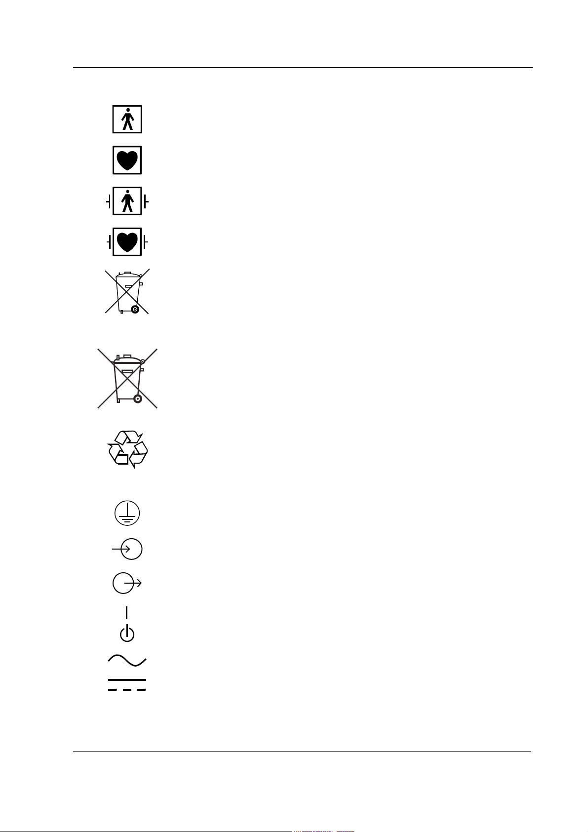
Battery charging LEDs: LEDs will blink while batteries are being charged, and will stay
illuminated when batteries are fully charged and the monitor is connected to mains.
The monitor is connected to the network (optional).
The DataCard (option) is inserted. If symbol is blinking the card is faulty, or it is not
inserted properly.
A blinking heart next to the heart rate or pulse rate value indicates the beats detected
A lung next to the respiration rate value indicates that respiration rate is calculated from
the impedance respiration measurement.
Silence alarm indicator. When displayed on the upper left corner of the screen, indicates
that all the alarms are silenced. When in the menu or digit fields, indicates that the
alarm source has been turned off.
Ethernet connectors
Printer connector
Sample gas outlet
Do not immerse the sensor in liquids.
ESD warning symbol for electrostatic sensitive devices. Pins of connectors identified
with the ESD warning symbol should not be touched. Connections should not be made
to these connectors unless ESD precautionary procedures are used. See section ”
ESD precautionary procedures“ in this Technical Reference Manual for details.
Symbol for non-ionizing electromagnetic radiation. Interference may occur in the vicinity
of equipment marked with this symbol.
1.5.2 Symbols on transport packaging
The contents of the transport package are fragile and have to be handled with care.
This symbol indicates the correct upright position of the transport package.
2.2
6
Document No. M1051339
The transport package must be kept in a dry environment.
Page 15

Introduction
This symbol is to indicate the temperature limitations within which the transport package
should be kept and handled.
Document No. M1051339
7
Page 16

Datex-Ohmeda S/5 Light Monitor
2 SAFETY
2.1 Safety precautions
2.1.1 Warnings
WARNING Indicates situations in which the user or the patient may be in danger of injury
or death.
Explosion hazard
• Do not use the monitor in presence of flammable anesthetics.
Electrical shock hazard
• Use only hospital grade grounded electrical outlets and power cord. Grounding reliability
can only be achieved when the equipment is connected to a receptacle marked ‘hospital
grade’.
• Do not remove cover. Refer servicing to qualified service personnel.
• Avoid any conductive contact to the probes and sensors.
• Disconnect the monitor from the electrical outlet before cleaning. Let it dry completely
before reconnecting it to the electrical outlet.
• Do not autoclave any part of the monitor with steam or ethylene oxide. Do not immerse in
liquid or allow liquid to enter the interior of any part.
• Make sure that external equipment is hospital grade grounded before connecting it to the
monitor. Do not connect any external equipment to the monitor, except that specified by GE
Healthcare.
• When connecting external equipment to the monitor, make sure that the whole combination
complies with safety standard IEC 60601-1-1 for the medical electrical systems and with
the requirements of local authorities. Non-medical electrical equipment connected to the
monitor shall be supplied from an extra isolating transformer which has a protectively
earthed outlet.
• Do not leave loose any sensor cables connected to patient. Either connect them to the
monitor or detach them from the patient.
• Do not use the monitor, any parts thereof or any accessories, if they have become wet or
exposed to liquid.
• Where the integrity of the external protective conductor installation or arrangement is in
doubt, equipment shall be operated from its internal power source.
8
Document No. M1051339
Page 17

Patient safety
Safety
• Always make sure that necessary alarm limits are set and operative when you start
monitoring.
• When the alarms are suppressed, observe the patient frequently.
• Connect only one patient to one monitor at a time.
• Constant attention by a qualified professional is needed whenever a patient is under
anesthesia or connected to a ventilator. Some equipment malfunctions may pass
unnoticed in spite of the monitor alarm.
• Do not use antistatic or electrically conductive breathing tubes. They may increase the risk
of burns when electrosurgery unit is utilized.
• Do not use the monitor during magnetic resonance imaging (MRI).
• ECG, Impedance Respiration, InvBP: Ensure proper contact of the return electrode of the
electrosurgery unit to your patient to avoid possible burns at sensor sites.
• ECG, Impedance Respiration, InvBP: Make sure that no part of the patient connections
touches any electrically conductive material including earth.
• Impedance Respiration: In obstructive apnea, thoracic movements and impedance
variations may continue.
• NIBP: The monitor sets the inflation pressure automatically according to the first
measurement. Reset the case to reset the inflation limit before measuring a new patient.
• PATIENTS WITH PACEMAKERS OR ARRHYTHMIAS: Monitor may count the pacemaker pulses
as heart beats during cardiac arrest, some arrhythmias, and with certain types of
pacemakers particularly in ON R mode. Do not rely entirely upon rate meter alarms. Keep
patients with pacemakers and arrhythmias under close surveillance.
• PACEMAKER PATIENTS: The impedance respiration measurement may cause rate changes
in Minute Ventilation Rate Responsive Pacemakers. Set the pacemaker rate responsive
mode off or turn off the impedance respiration measurement on the monitor.
• SpO
: A damaged sensor, or a sensor soaked in liquid, may cause burns during
2
electrosurgery.
• SpO
: Change measuring site frequently. Change sensor site and check skin and circulatory
2
status every 2-4 hours with adults, and every hour with small children.
• The output signals are not floating and they must not be connected directly to a patient.
• Do not use delayed analog signals for defibrillator or intra-aortic balloon bump
synchronization.
• The monitor is intended for use by qualified medical personnel only.
• InvBP: All invasive procedures involve risks to the patient. Use aseptic technique. Follow
catheter manufacturer’s instructions.
• InvBP: Use only defibrillator proof cables and transducers.
• Operation of the monitor outside the specified values may cause inaccurate results.
• The monitor or its components should not be used adjacent to or stacked with other
equipment. If adjacent or stacked use is necessary, the monitor and its components should
be observed to verify normal operation in the configuration in which it will be used.
Document No. M1051339
9
Page 18

Datex-Ohmeda S/5 Light Monitor
WARNING Use only approved accessories, mounts and defibrillator-proof cables and
invasive pressure transducers. For a list of approved supplies and accessories,
see the Supplies and Accessories catalog. Other cables, transducers and
accessories may cause a safety hazard, damage the equipment or system,
result in increased emissions or decreased immunity of the equipment or
system or interfere with the measurement. Protection against cardiac
defibrillator discharge is due in part to the accessories for pulse oximetry
), temperature (T) and invasive pressure (P) measurement.
(SpO
2
Single-use accessories are not designed to be re-used. Re-use may cause a risk
of contamination and affect the measurement accuracy.
Service
• Only trained personnel with proper tools and test equipment should perform the tests and
repairs described in this manual. Unauthorized service may void the monitor warranty.
• Switch the power off, unplug the power cord, and remove the batteries before service.
• The monitor is always energized with 12 V when the batteries are connected, even though
the power cord is removed and ON/STBY switch is in STBY position.
• Do not touch any exposed wire or conductive surface while covers are off and the monitor is
energized. The voltages present can cause injury or death.
• Electrostatic discharge through the PC boards may damage the components. Before
replacing PC boards, wear a static control wrist strap. Handle all PC boards by their nonconductive edges and use anti static containers when transporting them.
• Do not break or bypass the patient isolation barrier when testing LM-STP and LM-ECG
boards.
• Do not perform any testing or maintenance on the monitor while they are being used on a
patient.
• There are special components used in this monitor, which are vital to assure reliability and
safety. GE Healthcare assumes no responsibility for damage if replacement components
not approved by GE Healthcare are used.
• Replace the fuse with a fuse of the same type and the same rating.
• Perform electrical safety checks and current leakage tests to the monitor after service.
10
Document No. M1051339
Page 19

2.1.2 Cautions
CAUTION Indicates situations in which the unit or devices connected to it may be
damaged.
• Use licensed patient cables and accessories only, see Datex-Ohmeda Catalogue Patient
Monitor Supplies and Accessories. Other cables and accessories may damage the system
or interfere with measurement.
• Before connecting power cord, ensure that the input voltage selector is set correctly in the
external power adapter.
• Use the monitor outdoors with the battery power only.
• Do not store the monitor beyond the specified temperature range.
• Do not use hypochlorite, ammonia-, phenol- or acetone-based cleaners. They may damage
the monitor.
• Clean rear panel fan dust filter once a month or whenever needed.
• Leave space around the monitor for ventilation to prevent the monitor from overheating.
• Do not apply pressurized air to any outlet, or tubing connected to the monitor. Pressure may
destroy sensitive elements.
Safety
Battery cautions
• When used in moving vehicle mount the monitor properly.
• Dispose of the device and parts thereof in accordance with local regulations.
• Vibrations during transport may disturb SpO
, ECG, impedance respiration and NIBP
2
measurements.
• CO
• CO
• DataCards: Do not subject cards to excessive heat, bending, or magnetic fields.
• InvBP: Mechanical shock to invasive blood pressure transducer may cause severe shifts in
, SpO2: Do not apply force to sensors or sensor cables.
2
: Do not force the water-trap into place.
2
zero balance and calibration, and produce erroneous readings.
• Electromagnetic interference from radio-frequency transmitting devices in ambulances may
affect the performance of this medical device.
• Do not put in fire.
• Do not short-circuit any terminals.
• Do not use damaged or leaking batteries.
• Do not disassemble or break the batteries.
• Use only with Battery Module.
• Charge and discharge batteries fully every 3 months or more often, if required, to restore full
capacity.
• Sealed NiCd battery must be recycled or disposed properly. Discharge before disposing.
11
Document No. M1051339
Page 20

Datex-Ohmeda S/5 Light Monitor
Storage and transport
• For allowed storage and transport conditions refer to the documentation delivered with the monitor.
Points to note
• Medical electrical equipment needs special precautions regarding electromagnetic compatibility and
needs to be installed and put into service by qualified personnel according to the electromagnetic
compatibility information provided in the Appendix C.
• Portable and mobile RF communications equipment can affect the medical electrical equipment.
• The allowed cables, transducers and accessories for the system are listed in the Supplies and
Accessories catalog delivered with the monitor.
• The equipment is suitable for use in the presence of electrosurgery. Please notice the possible
limitations in the parameter sections and in the "Safety precautions" section.
• Service and reparations are allowed for authorized service personnel only.
• CISPR 11 classifications:
− Group 1 contains all ISM (Industrial, scientific and medical) equipment in which there is
intentionally generated and/or used conductively coupled radio-frequency energy which is
necessary for the internal functioning of the equipment itself.
− Class A equipment is suitable for use in all establishments other than domestic and those directly
connected to the public low-voltage power supply network that supplies buildings used for domestic
purposes.
2.2 ESD precautionary procedures
• To avoid electrostatic charges to build up, it is recommended to store, maintain and use the
equipment at a relative humidity of 30% or greater. Floors should be covered by ESD
dissipative carpets or similar. Non-synthetic clothing should be used when working with the
component.
• To prevent applying a possible electrostatic discharge to the ESD sensitive parts of the
equipment, one should touch the metallic frame of the component or a large metal object
located close to the equipment. When working with the equipment and specifically when the
ESD sensitive parts of the equipment may be touched, a grounded wrist strap intended for use
with ESD sensitive equipment should be worn. Refer to the documentation provided with the
wrist straps for details of proper use.
ESD precautionary procedure training
It is recommended that all potential users receive an explanation of the ESD warning symbol and
training in ESD precautionary procedures.
The minimum contents of ESD precautionary procedure training should include an introduction to
the physics of electrostatic charge, the voltage levels that can occur in normal practice and the
damage that can be done to electronic components if they are touched by an operator who is
electrostatically charged. Further, an explanation should be given of methods to prevent build-up of
electrostatic charge and how and why to discharge one’s body to earth or to the frame of the
equipment or bond oneself by means of a wrist strap to the equipment or the earth prior to making
a connection.
12
Document No. M1051339
Page 21

2.3 Safety test
Measure leakage current according to following procedures:
• Connect the GND electrode of the test device to the body of the 9-pin D-connector of the Light
Monitor. The nuts that are for locking the male cable connector can be used as well.
Safety
Document No. M1051339
13
Page 22

Datex-Ohmeda S/5 Light Monitor
3 ARCHITECTURE
The Light Monitor is a compact patient monitor with fixed configuration. The monitor is designed for
stationary and mobile indoor monitoring of a patient’s vital signs. The monitor can be equipped
with an optional recorder and battery module. An external power adapter is provided for power
supply.
3.1 Monitor structure
Keyboard
Patient
connector
panel
NIBP
ECG &
Respiration
InvBP(S),
TEMP(S) &
SpO2
MS-CO2
NESTPR
NIBP UNIT
Pwr data
ECG UNIT
STP UNIT
CO2 UNIT
Buttons &
ComWheel
POWER SUPPLY
Alarm leds
BOARD
Data buffers
Module bus
ECG
direct output
CO2 data
DSYNC,
NCALL
RS-232
Backlight
Inverter
CPU
BOARD
Display
Slave
Display
Speaker
Recorder
PCMCIA
ISA bus
Ethernet
Patient
isolated
14
Document No. M1051339
Battery data (12C)
Battery module
ECG Direct,
DSYNC, NCALL
Computer
Interface
Ext. power
supply: mains
or DC/DC
Battery #1
Battery #2
Figure 2 Main block diagram of Light Monitor, revision 03
The monitor can be divided into the following parts:
1. CPU board
The CPU board controls display and slave display, loudspeaker and recorder according the
data collected from the other units.
LM_blck_rev03_dgrm.vsd
Page 23

2. STP unit
The STP unit is a parameter board that measures invasive blood pressure(s), body
temperature and oxygen saturation of the blood (SpO2).
3. ECG unit
The ECG unit is a parameter board that measures 3-lead ECG.
4. NIBP unit
The NIBP unit is a parameter board that measures non-invasive blood pressure.
Architecture
5. CO
unit
2
The CO
unit measures carbon dioxide consentration of the respiration gases. Measurement
2
is performed by an OEM product manufactured by Welch Allyn.
6. Network unit
The unit enables connecting the Light Monitor to the network for remote monitoring the
patient and data collection.
7. Memory unit
The memory unit is an optional data storage module. It is used for storing patient related
physiological data by removable PC-card.
8. Power supply board
Board delivers power from one of the power sources, external power supply or one of the
two batteries. The other operations are:
• battery management: secondary battery charge/discharge control and capacity
gauge
• keyboard and ComWheel reading
• alarm and charge led control/drive
• buffering serial communication
9. Display
The display is 8.4” Active Matrix Color TFT LCD. The resolution is 640 x 480 pixels.
10. Printer
The built-in thermal printer provides a real time waveform printing, numerical data and trend
data printout up to 24 hours.
11. Battery module
Two rechargeable and removable secondary batteries are located in the separate battery
module.
12. Keyboard and Comwheel
Keyboard and ComWheel actions are read by the power supply board.
13. Backup Battery
Built-in NiCd battery is located inside the monitor. It provides typically up to 30 min
operation time to the monitor.
Document No. M1051339
15
Page 24

Datex-Ohmeda S/5 Light Monitor
3.2 Power supply unit
The power supply board functions can be summarized as follows:
• Charge the batteries.
• Choose between battery and mains operation.
3.3 CPU
• Distribute power to the CPU, CO
• Control the alarm LEDs.
• Read the input from the keyboard and ComWheel.
The CPU, CO
, STP, ECG, and NIBP boards are connected to the power supply board for centrally
2
, STP, ECG, and NIBP boards.
2
distributed power. Thus all signals transmitted between these boards are transmitted via the power
supply board. The power supply board controls the reset of the CPU board via the startup key.
The CPU board functions can be summarized as follows:
• Process the data transmitted from the CO
• Control the CO
• Control the display, loudspeaker and recorder.
• Generate alarm signals.
• Generate nurse call signal.
, STP, ECG, and NIBP boards.
2
, STP, ECG, NIBP and power supply boards.
2
The display, the loudspeaker and the recorder, are all connected directly to the CPU board. The
CPU board includes the circuitry required to control these units. The CPU board communicates with
the power supply board over a 9600 baud serial communication channel. The ECG, STP and NIBP
boards are connected to the CPU board via the power supply board. The CPU board communicates
with these boards over a 500 kbaud serial communications channel. The reset of the ECG, STP and
NIBP boards is controlled separately.
16
Document No. M1051339
The CPU board generates a nurse call signal in the event of an alarm situation. The signal is
transmitted via the power supply board to the serial I/O connector on the monitor rear panel.
Page 25

3.4 NIBP unit
The NIBP unit consists of the NIBP board, an air pump, and pneumatic valves. The NIBP board
functions can be summarized as follows:
• Control the function of the air pump and the pneumatic valves.
• Measure the pressure variation of the NIBP cuff.
The pressure variation of the NIBP cuff is analyzed on the NIBP board and transmitted to the CPU
board over a serial communication channel.
3.5 ECG unit
The ESTP board functions can be summarized as follows:
• Measure ECG
• Generate defibrillation synchronization signal
The ECG signal is monitored and analyzed on the ECG board and transmitted to the CPU board over
a serial communication channel.
The ECG board is electrically patient isolated. The operating voltage 10...16 V is generated from the
+ 12 V received from the power supply board. The ECG board is reset by the CPU board.
Architecture
The ECG board generates a defibrillation synchronization signal. The signal is transmitted via the
CPU and power supply board to the serial I/O connector on the monitor rear panel. The
defibrillation synchronization signal is available also on the patient connector on the patient
connector panel.
3.6 STP unit
The STP board functions can be summarized as follows:
• Measure SpO
The signals from the parameters being monitored are analyzed on the STP board and transmitted to
the CPU board over a serial communication channel.
The STP board is patient isolated. The operating voltage is generated from the +12 V voltage
received from the power supply board. The STP board is reset by the CPU board.
3.7 CO2 unit
The CO2 unit consists of the CO2 board, an isolated power supply, and a pump. The CO2 board
functions can be summarized as follows:
• Process the CO
• Generate end tidal and inspiratory CO
• Control the Mainstream CO
The waveform data is processed on the CO
communication channel.
, temperature and invasive blood pressure.
2
waveform generated by the mainstream CO2 sensor.
2
values, and breaths per minute data.
2
sensor motor and heater.
2
board and transmitted to the CPU board over a serial
2
Document No. M1051339
17
Page 26

Datex-Ohmeda S/5 Light Monitor
3.8 Display unit
The main CPU directly controls the monitor display, an 8.4 inch color LCD. Supply voltages for the
display are connected via the CPU board. The inverter board provides high voltage for the display
backlights. The CPU controls the display brightness by adjusting the backlight voltage.
NOTE: The LCD display backlight circuit runs on a high voltage. Do not touch the inverter
board or the backlight tube leads when powered.
3.8.1 Slave display
Internal VGA compatible display controller with 640 × 480 resolution. The slave display can be
connected to external VGA connector, X7.
3.9 Power adapters
3.9.1 N-LPOW
The external power adapter N-LPOW is connected to the power connector on the monitor rear panel. The adapter includes a switch for the voltage range and a LED indicating energization. The power adapter supplies 12.5 V to operate the monitor and 18.5 V to charge the batteries. Fuses are located on the primary side of the adapter for overvoltage protection. See the part II/7 for more information.
3.10 Host serial communications
3.10.1 Module bus
The module bus is an asynchronous, CMOS-level serial communication between host processor
and Datex-Ohmeda based parameter modules and CO
and RXDM signals are used. The TXDM signal is module bus transmit line from host to modules and
the RXDM signal is a receive line from modules to host. Modules are wired-OR connected to RXDM
line.
The module communication link is also provided in the D15 male connector on the rear panel.
3.10.2 Computer interface (RS-232)
The computer interface is an asynchronous, RS-232-level serial communication between the Light
Monitor and external device e.g. PC. External device is connected to the D15 male connector on
rear panel.
measurement by Welch Allyn. Only TXDM
2
18
Document No. M1051339
Page 27

3.10.3 CO2 module
The CO2 module, manufactured by Welch Allyn is used in the Light Monitor for CO2 mainstream
measurement. Communication with the host is provided by an asynchronous serial link. Signals
used in the communication are TXDC, RXDC. The TXDC signal is transmit line from host to CO
module and the RXDC signal is a receive line from CO
3.10.4 Power board
Host communicates with the power board on an asynchronous serial link. TXDP and RXDP signals
are used. The TXDP signal is transmit line from host to power board and the RXDP signal is a receive
line from power board to host.
3.10.5 Recorder
The host sends data to the printer via an asynchronous serial link. TXDR, RXDR, CTSR and RTSR
signals are used. The TXDR signal is transmit line from host to recorder and the RXDR signal is a
receive line from recorder to host CTSR and RTSR lines are used for handshaking.
module to host.
2
Architecture
2
Document No. M1051339
19
Page 28

Datex-Ohmeda S/5 Light Monitor
4 CLEANING
Before cleaning:
• Turn the power to Standby
• Disconnect the power cord from the mains power supply
After cleaning:
• Let dry completely
• Reconnect the power cord and turn the power ON
CLEANING CASING /
SURFACE
when needed
Wipe gently with a cloth, moistured
with a mild detergent.
Let dry completely before
reconnecting the power cord.
CLEANING DUST
FILTER
at least once a month
Pull out the filter frame on the rear
panel. Do not remove any screws!
Shake the filter and blow out the
dust.
If the filter is damaged, replace it
with a new one (p/n 888260).
PERMITTED CLEANERS PERMITTED DISINFECTANTS
Datex-Ohmeda cleaning fluid
Other mild detergents
For more detailed information see User’s Reference Manual.
Ethanol
Isopropyl alcohol
Chlorite compounds
Glutaraldehyde
CLEANING PATIENT
ACCESSORIES
See the instructions delivered with
the accessory.
NOT ALLOWED
Do not use Hypochlorite, acetone-,
phenol- or ammonia based cleaners.
Do not autoclave the device.
Do not immerse the device in liquids
or allow liquids to enter the interior of
any part.
20
Document No. M1051339
Page 29

5 FUNCTIONAL CHECK
These instructions include complete procedures for functional check (FC) for Datex-Ohmeda Light
Monitors. The functional check is recommended to be performed after monitor installation and
after long storage.
The first part of the instructions contains check procedures that are done through the service menu.
These checks are especially recommended if the monitor has been stored for a long time without
using it.
When installing a new monitor, the performance checks with a simulator and accessories are
typically enough to ensure the correct function of the monitor. We recommend however always
performing the complete check to confirm that no hardware failures occurred during transportation.
The instructions are planned for the maximum functional configuration. Perform the procedures in
the ascending order and skip the items that do not correspond to your monitor configuration.
The instructions include a check form (Appendix A) to be filled in when performing the
corresponding procedures.
Functional check
The symbol
checklist.
All menu selections related to
Monitor Setup - Install/Service (password 16-4-34) -
Service (password 26-23-8) – Modules - ESTP - ECG
Menu selections related to other products e.g. simulators are written in following typeface:
" in the instructions means that the performed procedure should be signed in the
Datex-Ohmeda products are written in following typeface:
RESP - WAVE - NORM
- RATE - 20
Recommended tools:
Tool Order No.
Simulator capable of simulating ECG, RESP and invBP -
SpO2 finger probe SAS-F4
Adult NIBP cuff 572435
Adult NIBP hose 877235
MemCard- Data (only for monitors with data card option)
Temperature test plug set 884515
Mainstream CO2 sensor (only for monitors with CO2 option) 902300
Mainstream CO2 airway adapter (only for monitors with CO2 option) 902301/902302/902303
5.1 General functional inspection
1. Connect the power cord to the power adapter and the power adapter cable to the Light
Monitor.
Check that the green LED turns on in the power adapter and the LED in the lower right-hand
corner of the monitor turns on or starts flashing.
If the monitor contains a battery module, check that both battery charge status LEDs turn on
or start flashing.
Document No. M1051339
21
Page 30

Datex-Ohmeda S/5 Light Monitor
2. Switch the monitor on. Check that the monitor starts up properly, i.e.
− both alarm LED’s turn on and off
− the fan starts running
− the start-up sound is heard from the loudspeaker
− the normal monitoring screen appears
− no error messages appear on the screen *)
− If the monitor contains a recorder, two lines of start-up information should be
− check that the time and date are correct, adjust if necessary
− if the monitor contains an F-LBAT or N-LBB, check that the battery symbol is
3. Check the loudspeaker by adjusting the alarm volume in the Alarms Setup menu:
Press the
Select Alarms Setup - Alarm Volume
Test the whole volume scale from 1 to 10 by turning the ComWheel and check that the
alarm volume changes correspondingly. The alarm sound should be clear and audible at all
settings.
Select Main Menu
recorded
displayed
*) NOTE: “Check network connectors” will appear if the N-LNET or N-LDNET option is
installed.
Menu button.
4. Select Service View – Keyboard - Dummy Press.
Press the function keys one by one. Check that each key generates a sound from the
loudspeaker and the corresponding text.
5. Check that the time and date are correct, adjust if necessary.
Select Monitor Setup – Set Time and Date
NOTE: You cannot change the monitor’s time settings after a case has started. This prevents
losing the trend data.
NOTE: If the clock shows time 0:00 continuously after start-ups, the SRAM/Timekeeper’s
battery on the CPU board needs to be replaced.
Return to Main Menu by selecting Previous Menu - Main Menu
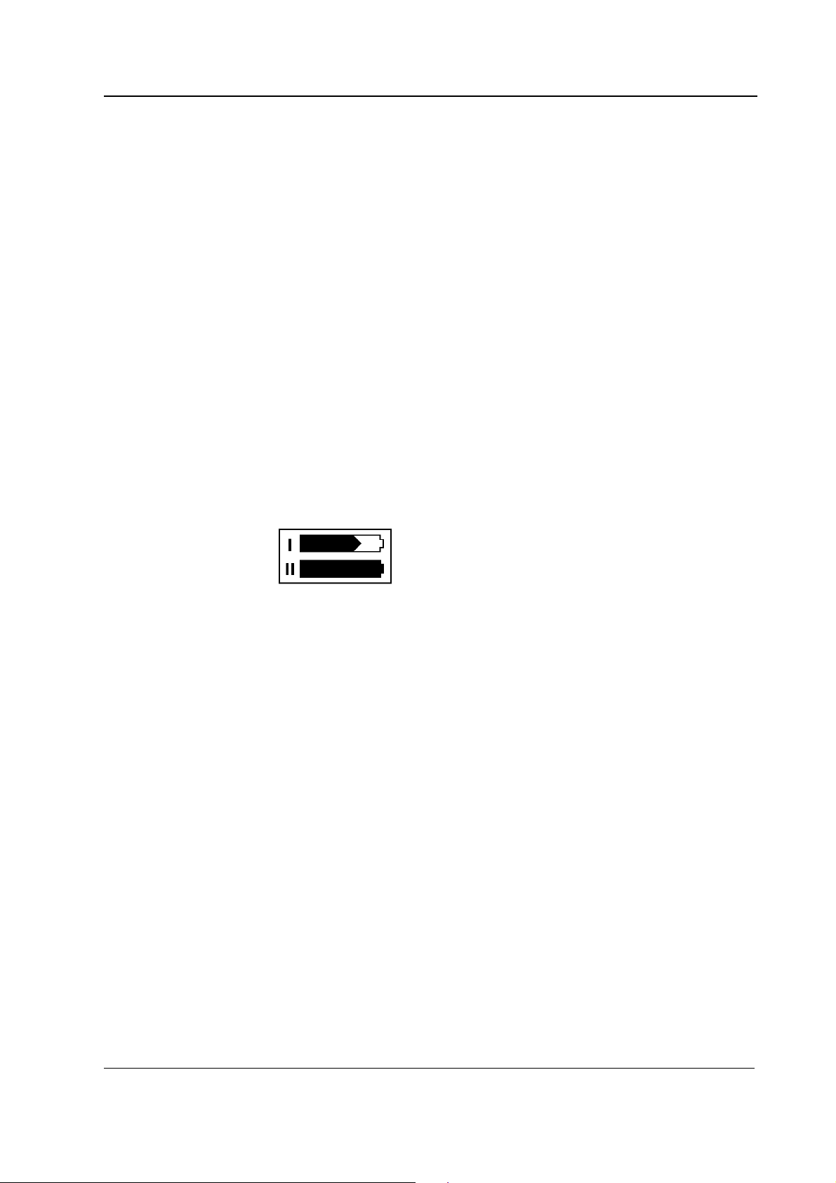
6. Check the battery (If F-LBAT or N-LBB option included):
Disconnect the power cord (without switching the monitor to standby).
Check that the monitor continues to run normally with battery. The battery indicator should
appear in the upper right hand corner of the screen:
22
Document No. M1051339
Page 31

"
5.1.1 Recorder test
7. Open the paper compartment cover. Check that the message “Recorder: Cover open”
8. Select Main Menu - Record/Print- Record Wave
Functional check
Reconnect the power cord and check that during charging, the charging symbol is displayed
and the Battery charge status LED starts flashing:
appears on the screen, then close the cover.
and check that the recorder starts recording. Select Stop Wave to stop recording.
Check that the quality of the recordings is acceptable.
"
5.1.2 PCMCIA card test
9. Insert the Memory card labeled “Data” in the DataCard slot. Check that the message “Data
Card inserted” appears in the message field and the white data card symbol in the upper
right hand corner of the screen appears within one minute.
"
Document No. M1051339
23
Page 32

Datex-Ohmeda S/5 Light Monitor
5.1.3 Network test
10. Connect the Mon-Net cable and the Identification plug to the monitor.
11. Check that the monitor connects to the Datex-Ohmeda Network, i.e. the network symbol
A message regarding the connection to Datex-Ohmeda Information Center should appear in
the message field on the screen.
12. Press the Menu button to enter the Network service menu:
Monitor Setup - Install/Service (Password 16-4-34) -
Service View (Password 26-23-8) - Monitor - Communication
Check that:
− the “location ID number” matches with the ID plug connected to X3
− the packets and bytes IN is increasing slowly
− the packets and bytes OUT is increasing quickly.
− the “connections” shows the names of the connected networks
− the counters for data errors (“CRC”, “Frame”, “Transm.”) are stable
NOTE: The counters may show values greater than 0. However, any values increasing
continuously indicate a problem.
is displayed on the upper right-hand corner of the screen.
13. Check that the counters for hardware errors (“Intern.”, “Missed”, “FIFO”, “Overrun”) all
show 0. If any of the counters show a value greater than 0, it indicates a problem on the
CPU board.
Return to the Monitor Setup menu by selecting Previous Menu repeatedly.
"
24
Document No. M1051339
Page 33

5.1.4 ECG board tests
14. Enter the ESTP : ECG service menu:
Press the
Monitor Setup - Install/Service (Password 16-4-34) -
Service View (Password 26-23-8) - Modules - ESTP : ECG
Check from the Service Data that:
− the “Timeouts”, “Bad checksums” and “Bad c-s by mod” values are not increasing
− the ECG/RESP board memories have passed the internal memory test, i.e. “RAM”,
15. Check that the module mains power frequency “Power Freq” value has been set according
to the supply frequency. If necessary, change the setting by selecting Power Freq.
16. Check that the “Resp Available” and “Resp measurement” both show ON.
NOTE: The Resp measurement shows OFF, if Resp is not selected to the screen setup. To
setup the screen, press the
Digit Fields.
Functional check
Menu button and select:
faster than by 50 per second.
“ROM” and “EEPROM” all state OK.
Menu key and select: Monitor Setup - Waveform Fields or
"
5.1.5 STP board tests
17. Enter the ESTP : STP service menu:
− Check that the “Timeouts”, “Bad checksums” and “Bad c-s by mod” values are not
increasing faster than by 50 per second.
− Check that the STP board memories have passed the internal memory test, i.e. “RAM”,
“ROM” and “EEPROM” all show OK.
18. Check that the protection for temperature calibration is on:
“Protect key” text in the menu should state OFF.
“Protect mode” text should state ON.
If necessary, change the protection mode in the Calibrations menu.
"
Document No. M1051339
25
Page 34

Datex-Ohmeda S/5 Light Monitor
5.1.6 NIBP board test
19. Enter the NIBP service menu:
Check that the “Timeouts”, “Bad checksums” and “Bad c-s by mod” values are not
increasing faster than by 50 per second.
Check that the NIBP board memories have passed the internal memory test, i.e. “RAM”,
“ROM” and “EEPROM” all show OK.
"
5.1.7 Mainstream CO2 test
20. Enter the CO2 service menu:
Press the
Monitor Setup - Install/Service (Password 16-4-34) -
Service View (Password 26-23-8) - Modules – CO2
Check from the Service Data that: “Timeouts”, “Bad checksums” and “send queue full”
values are not increasing faster than by 50 per second.
A value increasing faster than this indicates a failure in Module Bus communication.
"
Menu button and select:
26
Document No. M1051339
Page 35

5.2 Performance checks
1. Connect a 5-lead cable to the monitor. Configure the monitor screen so that all parameter
information is displayed, for example for the maximum configuration:
Press the
Monitor Setup - Waveform Fields/Digit Fields
Waveform Fields Digit Fields
Field 1 - ECG1 Field 1 -Temp
Field 2 - P1 Field 2 – NIBP
Field 3 – P2 Field 3 – Pleth
Menu button to enter the Main Menu and select:
Functional check
Field 4 - Resp Field 4 - CO
Return to
Connect the patient simulator and check that all parameter information is displayed as
configured on the screen.
NOTE: InvBP waveforms are not shown without a patient simulator.
Preset measurement settings for parameters, for example as follows:
Normal Screen.
2
ECG & Resp - ECG Setup - HR Source – AUTO
- Resp Setup - Size - 1.0
- Resp Rate Source - AUTO
- Detection Limit - AUTO
NOTE: The RESP waveform or Digit Field has to be selected on the screen before the
respiration measurement can be turned on.
NIBP & Inv. Press - P1 Setup&Alarm - Label - ART
- P2 Setup&Alarm - Label - CVP
Press the
- Pleth Scale - AUTO
Menu button to enter the SpO2 & Temp and select
"
Document No. M1051339
27
Page 36

Datex-Ohmeda S/5 Light Monitor
2. Connect the patient simulator to the ECG and InvBP connectors, SpO
connector and temperature test plug to the Temp connector. Attach the SpO
finger and check that:
− the simulated waveforms are good
− the SpO
− the Pleth waveform is normal.
"
3. Set the InvBP simulator to +100 mmHg static pressure. Push the Zero All button and
check that:
− the InvBP waveforms set on the baseline
− the digital values go to zero
Set the simulator to 0 mmHg and press
the zeroing, turn the simulator to dynamic mode and check that the waveform is normal.
"
4. Check that the message “No probe” is displayed when there is no SpO
Connect a SpO
displayed when the probe is not connected to finger.
value is in expected range
2
Zero All button. After the monitor has completed
finger probe to the monitor and check that the message “Probe off” is
2
probe to the SpO2
2
probe on your
2
sensor connected.
2
"
5. Attach the SpO
pleth waveform is displayed and the SpO
Check that the HR value is calculated from SpO
connected.
sensor to your finger and check that after the message “Pulse search” the
2
value is in the expected range (95-99 %).
2
when ECG and InvBP (P1) cables are not
2
"
6. Remove the SpO2 sensor from your finger and check that the message “Probe off” is
displayed. Disconnect the sensor from the monitor and check that “No probe” message is
displayed.
"
7. Attach an adult NIBP cuff onto your arm and perform one NIBP measurement. Check that
the module identifies the cuff, i.e. the text “Adult” appears in the NIBP digit field for a short
time.
Check that the module gives a reasonable measurement result.
"
28
Document No. M1051339
Page 37

Functional check
8. Check that the message “No CO2 sensor” is displayed when there is no CO
connected. Connect a CO
displayed.
"
9. Wait until the “warming” message disappears and the CO
Breathe at least 5 times to the CO
are reasonable and the Respiratory value is calculated.
"
• Fill in all necessary documents.
sensor to the monitor and check that the message “warming” is
2
value appears on the screen.
2
sensor adapter and make sure that the measured values
2
sensor
2
Document No. M1051339
29
Page 38

Datex-Ohmeda S/5 Light Monitor
6 SERVICE CHECK
6.1 General service information
Field service of the Light Monitor is limited to replacing faulty printed circuit boards or mechanical
parts. Faulty printed circuit boards should be returned to GE Healthcare for repair.
GE Healthcare is always available for service advice. Please provide the unit serial number, full type
designation, and a detailed description of the fault.
The instructions are planned for the maximum functional configuration. Perform the procedures in
the ascending order and skip the items that do not correspond to your monitor configuration.
CAUTION Only trained personnel with appropriate equipment should perform the tests and
repairs outlined in this section. Unauthorized service may void warranty of the unit.
6.2 Service check procedure
These instructions include complete procedures for service check. The service check is
recommended to be performed after any service repair, however, the service check procedures
can be used also for determining possible failures.
The procedures should be performed in ascending order.
The instructions include a check form (Appendix B) which should be filled in when performing the
procedures.
Names of the keys are written in bold Helvetica typeface, for example
Selectable menu items are written in bold and italic typeface, for example Previous Menu.
Informative messages displayed on the screen are written in normal typeface, but separated with
quotation mark, for example ‘Please wait’.
The mark
check form.
The procedures are designed for monitors with monitor software of level 894727-4.1. However, for
the most part they apply to monitors with older monitor software as well.
Recommended tools
Tool Order No.
Patient simulator for ECG, Impedance Resp and BP -
Pressure manometer -
Temperature test set 884515
3- and 5-lead ECG cable -
SpO2 finger probe OXY-F4-N
InvBP transducer 78000
Adult NIBP cuff 572435
Adult NIBP hose 877235
Infant NIBP hose 877514
Infant NIBP cuff 877407
Mainstream CO2 sensor (only for monitors with 902300
Normal Screen.
" in the instructions means that the performed procedure should be signed in the
30
Document No. M1051339
Page 39

Tool Order No.
CO2 option)
Mainstream CO2 airway adapter (only for monitors
with CO2 option)
Screwdriver -Pozidrive- type
MemCard- Data (only for monitors with data card
option)
Recommended parts
Service check
902301/902302/
902303
Part Order No.
Fan filter 886841
Recorder paper 74205 if N-LREC option
6.2.1 Visual inspection
• Switch the monitor to standby
• Disconnect all the connection cables from the monitor’s rear panel.
1. Check internal parts:
− Make visual inspection for all external parts of the monitor. Check e.g. that the power
− Connect the power cord to the power adapter and check the supply voltage from the
Pin Signal
2
4
3
1
Notes
installed
cord receptacle is intact in the power adapter.
power adapter’s connector. PIN 1 voltage must be 12.7 V without load (Figure 1). If
necessary, adjust the 12.7 V with trimmer R23 (Figure 2).
1
2
3
4
12.7 V
GND
18.5 V
GND
Figure 1 Power adapter’s voltages
Document No. M1051339
31
Page 40

Datex-Ohmeda S/5 Light Monitor
Figure 2 Adjustment trimmer R23 in N-LPOW
− Clean or replace the fan filter.
− Clean the recorder unit, if necessary.
− Check that all shielding flaps (6 pcs) are properly closed. (Figure 3)
R23
Shielding Flaps
(6 pcs)
Figure 3 LM1-STP board EMC covers
"
2. Check external parts:
32
Document No. M1051339
− the patient panel sticker is intact
− all connectors are intact and attached properly
Page 41
− both screws on the patient panel are tightened properly
"
3. General functional inspection
− Connect the power cord to the Power Adapter and the Power Adapter cable to the Light
Monitor.
Check that the green LED turns on in the power adapter and the LED on the lower right-hand
corner of the monitor turns on or starts flashing.
Check that both Battery charge status LEDs turn on or start flashing.
− Switch the monitor on. Check that the monitor starts up properly, i.e.
− both alarm LEDs turn on and off
− the fan starts running
− the start-up sound is heard from the loudspeaker
− the normal monitoring screen appears
− no error messages appear on the screen *)
− if the monitor contains a recorder, two lines of start-up information should be recorded
Service check
− check that the time and date are correct, adjust if necessary
− if the monitor contains an F-LBAT or N-LBB, check that the battery symbol is displayed:
*) NOTE: ”Check network connectors" will appear if the N-LNET or N-LDNET option is installed.
− Enter the service menu and select Dummy Press.
Press the function keys one by one. Check that each key generates a sound from the
loudspeaker and the corresponding text.
"
4. Screen setup
− Configure the monitor screen according to the monitor configuration so that all necessary
parameter information is displayed, for example as follows:
Menu - Monitor Setup- Waveform Fields - Field 1 - ECG1
- Field 2 – P1
- Field 3 – P2
- Field 4 - Resp
- Digit Fields - Lower Field 1 - NIBP
- Lower Field 2 – CO2
- Lower Field 3 – Pleth
- Lower Field 4 – Temp
− Connect the patient simulator to the monitor and check that all needed parameter
information is shown on the screen.
NOTE: The RESP waveform or Digit Field has to be selected on the screen before the respiration
measurement can be turned on.
Document No. M1051339
33
Page 42
Datex-Ohmeda S/5 Light Monitor
5. Preset ECG, Respiration, InvBP and SpO
measurement settings:
2
ECG & Resp - ECG Setup - Hr Source - Auto
- Pacemaker - Show
- Resp Setup - Size - 1.0
- Resp Rate Source - Auto
- Measurement - On
- Detection Limit - Auto
NIBP & Inv. Press - P1 Setup&Alarm - Label - Art
P2 Setup&Alarm - Label - Cvp
SpO2 & Temp - Pleth Scale – Auto
6. Press the Menu button and check the loudspeaker by adjusting the alarm volume in the
Alarms Setup menu:
− Test the whole volume scale from 1 to 10 by turning the ComWheel and check that the
alarm volume changes correspondingly. The alarm sound should be clear and audible at
all settings.
7. Select Service View – Keyboard – Dummy Press.
Press the function keys one by one. Check that each key generates a sound from the
loudspeaker and the corresponding text.
"
8. Check that the time and date are correct, adjust if necessary:
Menu – Monitor Setup – Set Time and Date
− NOTE: You cannot change the monitor’s time settings after a case has started. This
prevents losing the trend data.
− NOTE: If the clock shows time 0:00 continuously after start-ups, the SRAM/Timekeeper’s
battery on the CPU board needs to be replaced.
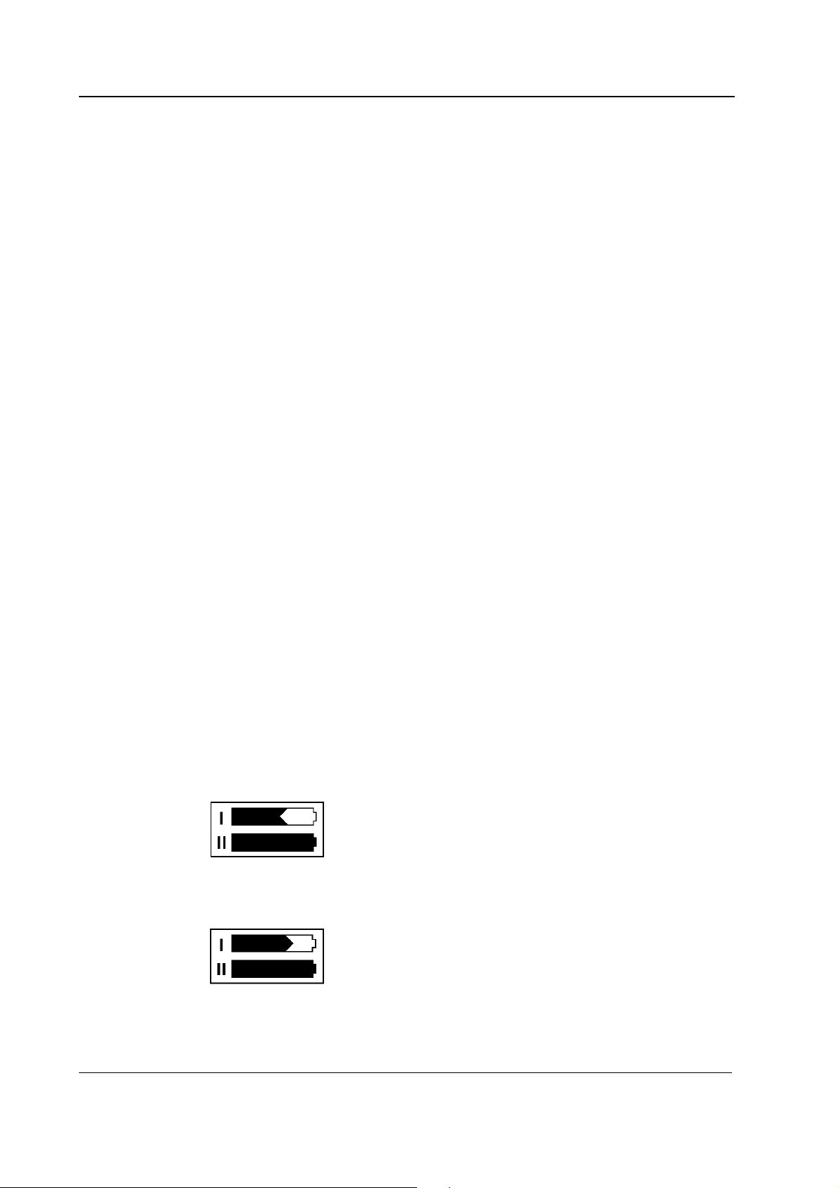
9. Check the battery (If F-LBAT or N-LBB option included):
Disconnect the power cord (without switching the monitor to standby).
Check that the monitor continues to run normally with battery. The battery indicator should
appear in the upper right hand corner of the screen:
Reconnect the power cord and check that during charging, the charging symbol is displayed
and the Battery charge status LED starts flashing:
34
Document No. M1051339
Page 43

6.2.2 Recorder test
10. Open the paper compartment cover. Check that the message “Recorder: Cover open”
appears on the screen, then close the cover.
11. Select Main Menu - Record/Print- Record Wave
and check that the recorder starts recording. Select Stop Wave to stop recording.
Check that the quality of the recordings is acceptable.
"
6.2.3 PCMCIA card test
12. Insert the Memory card labeled “Data” in the DataCard slot. Check that the message “Data
Card inserted” appears in the message field and the white data card symbol in the upper
right hand corner of the screen appears within one minute.
"
6.2.4 Network test
Service check
13. Connect the Mon-Net cable and the Identification plug to the monitor.
14. Check that the monitor connects to the Datex-Ohmeda Network, i.e. the network symbol
is displayed on the upper right-hand corner of the screen.
A message regarding the connection to Datex-Ohmeda Information Center should appear in
the message field on the screen.
15. Press the Menu button to enter the Network service menu:
Monitor Setup - Install/Service (Password 16-4-34) -
Service View (Password 26-23-8) - Monitor - Communication
Check that:
− the “location ID number” matches with the ID plug connected to X3
− the packets and bytes IN is increasing slowly
− the packets and bytes OUT is increasing quickly.
− the “connections” shows the names of the connected networks
− the counters for data errors (“CRC”, “Frame”, “Transm.”) are stable
NOTE: The counters may show values greater than 0. However, any values increasing
continuously indicate a problem.
16. Check that the counters for hardware errors (“Intern.”, “Missed”, “FIFO”, “Overrun”) all show
0. If any of the counters show a value greater than 0, it indicates a problem on the CPU
board.
Return to the Monitor Setup menu by selecting Previous Menu repeatedly.
"
Document No. M1051339
35
Page 44

Datex-Ohmeda S/5 Light Monitor
6.2.5 ECG measurement
17. Enter the service menu:
Menu - Monitor Setup - Install/Service (Password 16-4-34) -
Service View (Password 26-23-8)
Take down the information regarding monitor software and unit id by selecting Scroll Vers
and turning the ComWheel or choose Record Vers if the recorder is installed.
"
18. Enter the ESTP : ECG service menu:
Menu - Monitor Setup - Install/Service (Password 16-4-34) -
Service View (Password 26-23-8) - Modules - ESTP : ECG
Check that the “Timeouts”, “Bad checksums” and “Bad c-s by mod” values are not
increasing faster than by 50 per second. Check also that the ECG/RESP board memories
have passed the internal memory test, i.e. the “RAM”, “ROM” and “EEPROM” state all OK.
19. Check that the power frequency value has been set according to the current mains power
frequency. Change the setting by selecting Power Freq, if necessary.
20. Connect a 5-lead ECG cable to the module. Check that the “Cable type” shows 5 lead. If it
shows 3 lead, make sure the used 5-lead ECG cable contains the necessary wiring for cable
recognition (pins 0, 8 and 9 connected together).
21. Check that all the electrodes show OFF in the service menu and the message “Leads Off” is
shown on the screen.
Connect all the leads together, for example to a suitable screwdriver. Check that all the
electrodes show ON and the message “Asystole” appears.
Disconnect one of the leads and check that the corresponding electrode in the service
menu shows OFF within 10 seconds from the disconnection, then reconnect the lead. Check
the rest of the leads using the same method.
NOTE: When the ground lead (black) is disconnected all the electrodes should show OFF.
NOTE: The asystole and different leads off -messages are shown using certain priority, so
even if only
appear on the screen.
one of the leads is disconnected, the lead related leads off -message may not
36
Document No. M1051339
"
22. Connect a 3-lead cable to the monitor.
Connect the leads together (e.g. to a screwdriver).
Select one lead (I, II or III) for display.
Detach a lead from the screwdriver, and see that the monitor responds as described in the
table below. Connect the lead again and check that “Leads off” message disappears.
Page 45

Lead selection Lead to be detached Message
Lead I L/LA
R/RA
N/LL
Lead II L/LA
R/RA
N/LL
Lead III L/LA
R/RA
N/LL
Leads off
Leads off
Leads off
Leads off
Leads off
Leads off
Leads off
Leads off
Leads off
Check that in any case the correspondence electrode (RA, LA or LL) shows off. Electrodes V
and RL show off all the time. In cases I and N, II and R, III and L all electrodes show off.
23. Connect the leads to a patient simulator.
The settings and checks with Dynatech NevaIIda MedSim 300 Patient Simulator:
ECG - BASE - BPM - 160
PACE - WAVE – NSR
Service check
Check that normal ECG waveform is shown, the HR value is 160 (±5) and the “Pacer count”
value is not increasing in the service menu
ECG - PACE - WAVE – ASNC
Check that pacemaker spikes are shown on the ECG waveform, the HR value changes to 75
(±5) and the “Pacer count” value is increasing according to shown pacemaker spikes.
Set the pacemaker option off:
ECG - PACE - WAVE - NSR
"
6.2.6 Respiration measurement
24. Check that the “Resp Available” and “RESP Measurement” show both ON in the ESTP : ECG
service menu.
Do the following settings:
Menu - ECG & Resp – ECG Lead – II
and use a 3-lead ECG cable.
25. Check the respiration measurement with a patient simulator.
The settings and checks with Dynatech Nevada MedSim 300 Patient Simulator:
BASELINE IMPEDANCE LEAD SELECT-
switch - II/RL-LL
switch - 500
RESP - WAVE - NORM
RATE - 20
OHMS - 1.0
Document No. M1051339
37
Page 46

Datex-Ohmeda S/5 Light Monitor
RATIO - 1/1
APNEA - OFF
SHIFT – OFF
Check that the Resp waveform is shown and the RR value is 20 (±5). Change the position of
the BASELINE IMPEDANCE -switch and check that appropriate RESP waveform and RR
value are shown again within 30 seconds.
RESP - APNEA - 32 S
Check that the monitor gives the APNEA alarm.
NOTE: Make sure that only the ECG leads are connected to the simulator during the apnea
test. If other cables are connected at the same time, the respiration signal from the
simulator may be disturbed, and therefore, the APNEA alarm may not be activated.
NOTE: When you have the ECG service menu open, spikes will appear on the respiration
waveform. These spikes represent the threshold level for detecting inspiration and
expiration.
"
38
Document No. M1051339
Page 47

6.2.7 Temperature measurement
26. Enter the ESTP : STP service menu:
Modules - ESTP : STP
Check that the “Timeouts”, “Bad checksums” and “Bad c-s by mod” values are not
increasing faster than by 50 per second. Check also that the STP board memories have
passed the internal memory test, i.e. the “RAM”, “ROM” and “EEPROM” show all OK.
27. Check that the “Cable” and “Probe” show OFF for channel T1 when no probe is connected.
Connect a temperature test plug into the connector T1. Check that the “Cable” and “Probe”
for T1 show ON and the corresponding temperature value appears on the monitor screen.
28. Check the temperature calibrations using temperature test plugs. If the deviation on a
temperature reading on the screen is more than 0.1 °C, calibrate the temperature channels
according to the instructions in the Technical Reference Manual.
Service check
29. Activate the temperature test by selecting Temp Test from the menu and pressing the
ComWheel twice. When the message “Performing temp test” disappears from the digit field,
check that no error messages appear and “Temp error” shows OFF for both channels in the
service menu.
30. Check that the module configuration has been set correctly. The configuration in use is
shown beside the text “Configuration” in the service menu and it can be either STP, ST or TP.
Change the configuration in the Calibrations menu, if necessary.
6.2.8 Invasive blood pressure measurement
31. Check that the “Cable” and “Probe” for P1 show OFF. Plug a cable with an invasive blood
pressure transducer into the front panel connector P1 and check that the “Cable” and
“Probe” show ON and the corresponding pressure waveform appears on the screen.
Perform the same check also for the InvBP channel P2.
32. Calibrate the InvBP channels P1 and P2 according to the instructions in the Technical
Reference Manual.
Document No. M1051339
39
Page 48

Datex-Ohmeda S/5 Light Monitor
33. Check the InvBP channels with a patient simulator.
The settings and checks with Dynatech Nevada MedSim 300 Patient Simulator:
SENSITIVITY -
ECG - BASE - BPM - 60 - BP - 1 - WAVE - ATM
2 - WAVE - ATM
switch - 5 µV/V/mmHg
Restore the normal monitoring screen by pressing the key
Connect cables from the channels BP1 and BP2 to the patient connectors P1 and P2. Zero
the InvBP channels by pressing the ZERO ALL button on the monitor front panel.
Check that appropriate InvBP waveforms are shown and the InvBP values are approximately
120/80 (±3 mmHg) for the channel P1 and 15/10 (±2 mmHg) for the channel P2.
Check that the HR value is calculated from P1 when ECG is not measured (ECG cable
disconnected).
"
6.2.9 SpO2 measurement
34. Check that the message “No probe” is shown when no SpO2 sensor is connected to the
module. Connect an SpO
is shown when the probe is not connected to a finger.
35. Connect the SpO
waveform appear. Check that the HR value is calculated from SpO
(P1) are not measured.
BP - 1 - WAVE - ART
2 - WAVE - CVP
2
probe onto your finger. Check that the reading of 95-99 and SpO2
2
Normal Screen.
finger probe to the module. Check that the message “Probe off”
when ECG and InvBP
2
40
Document No. M1051339
"
Page 49

6.2.10 Non Invasive Blood Pressure measurement
36. Enter the NIBP module service menu:
Monitor Setup - Install/Service (Password 16-4-34) -
Service (Password 26-23-8) - Modules - NIBP
Check that the “Timeouts”, “Bad checksums” and “Bad c-s by mod” values are not
increasing faster than by 50 per second. Check also that the NIBP board memories have
passed the internal memory test, i.e. the “RAM”, “ROM” and “EEPROM” show all OK.
37. Check the pump and valves.
Highlight Pneumatics from the NIBP menu. Connect a pressure manometer to the NIBP
module cuff connector.
Select Start Pump and press the ComWheel. Check that the pump turns on and the
pressure inside the tubing system starts to increase. Stop the pump by pressing the
ComWheel again when the pressure reaches 280 mmHg.
Highlight Open Exh1. Press the ComWeel and check that the pressure inside the tubing
system starts to drop, then press the ComWheel again. Check the other exhaust valve in the
same way by selecting Open Exh2 from the menu.
If necessary, turn the pump on again for a moment to increase the pressure inside the
tubing system.
Highlight SET VALVE. Press the ComWheel and set the value under the text “Pulse Valve” to
number 120 by turning the ComWheel. Press the ComWheel again and check that the
pressure inside the tubing system starts to drop. Finish the test by selecting Previous Menu.
Service check
38. Check the NIBP tubing system for leakages.
Select Calibrations from the NIBP service menu.
Connect the pressure manometer to the NIBP module cuff connector. Start the active leak
test from the menu by pressing the ComWheel. The module pumps a pressure of about 265
mmHg and then the pump stops.
Wait for 15 seconds for the pressure to stabilize, then check that the pressure does not drop
more than 6 mmHg per one minute. Release the pressure by pressing the ComWheel once
more.
39. Calibration check.
Recalibrate the NIBP measurement. Remember to set the calibration protection back on
after calibration.
Disconnect the pressure manometer. Select Calibrations and then highlight Calibration
Check. Press the ComWheel and take down the zero offset values for both pressure
transducers, B1 and B2. The values should be within ±10 mmHg.
Connect the pressure manometer to the cuff connector and check the calibration with
pressures 100 mmHg, 200 mmHg and 260 mmHg. The zero offset value must be added to
Document No. M1051339
41
Page 50

Datex-Ohmeda S/5 Light Monitor
the displayed pressure value in order to determine the real pressure.
40. Check the watchdog timer activation pressure.
Select Pneumatics from the NIBP service menu.
Keep the pressure manometer connected to the cuff connector. Pump up the pressure very
slowly and note the value on the manometer when you hear a signal from the loudspeaker.
The pressure at where the watchdog timer should activate with an audible signal is
13 mmHg (11…15 mmHg).
Adjust the limit with the trimmer on the NIBP board, if necessary.
41. Check the watchdog timer.
Select Watchdog from the NIBP service menu.
Check the watchdog timer in the adult mode. Activate the timer by highlighting Test Adult
and then pressing the ComWheel. Check that the time beside the text “Watchdog Interval”
starts to run. Wait until you hear a signal from the loudspeaker and then check the time
again. The time from the adult test should fall within 120-140 seconds.
Check the watchdog timer also in the infant mode by first selecting Test Infant from the
menu. The time from the infant test should fall within 60-70 seconds.
42. Check the safety valve.
Select Safety Valve from the NIBP service menu.
Keep the pressure manometer connected to the cuff connector.
NOTE: Make sure your pressure manometer can be used to measure pressures over 300
mmHg. If such a pressure manometer is not available, perform the check with an adult cuff
that is connected around some round object, for example a calibration gas bottle.
Highlight Start Test. Start the adult safety valve test by pressing the ComWheel. Wait until
the pump stops and the pressure is deflated. Check the pressure values “Max press” and “2
s after stop” for both transducers. All the values should be within 290 - 330 mmHg.
Highlight Adult. Press the ComWheel and check that the text changes now to INFANT. Select
Start Test and wait until the pump stops and the pressure values on the screen have been
updated. Check that the values “Max press” and “2 s after stop” are all now within
154...165 mmHg.
Return to the normal monitoring mode by pressing
Normal Screen.
43. Connect an adult NIBP cuff to the cuff connector and disconnect one of its hoses.
Start NIBP measurement by pressing the key
NIBP, highlight Start Manual and press the
ComWheel and check that the message “Cuff loose” appears on the screen within 30
seconds.
Reconnect the hose and then bend it with your fingers. Restart the measurement and check
42
Document No. M1051339
Page 51

Service check
that the message “Cuff occlusion” appears on the screen within 30 seconds.
Check that automatic inflation limits are in use:
Menu – NIBP & Inv.Press - NIBP Setup&Alarm - Inflation Limits – Auto
Previous Menu
44. Connect the cuff onto your arm, highlight START VEN.STASIS in the NIBP & Inv.Press menu
and press the ComWheel. Check the module identifies the cuff, i.e. the text “Adult” appears
in the NIBP digit field for a short moment.
Keep the pressure inside the cuff for about half a minute in order to see that the cuff is not
leaking, then press the ComWheel again. Select
45. Keep the cuff on your arm and perform one NIBP measurement. Check that the monitor
gives a reasonable measuring result.
46. Connect an infant cuff to cuff connector and wrap it around your fingers.
Start NIBP measurement and check that the module identifies the cuff, i.e. the text “Infant”
appears in the NIBP digit field. Cancel the measurement after the cuff identification.
Normal Screen.
"
6.2.11 Mainstream CO2 measurement
47. Enter the CO2 service menu and check that the “Timeouts”, “Bad checksums” and “send
queue full” values are not increasing faster than by 50 per second.
48. Check that the message “No CO2 sensor” is displayed when there is no CO2 sensor
connected. Connect a CO2 sensor to the monitor and check that the message “warming” is
displayed.
49. Wait until the “warming” message disappears and the CO2 value appears on the screen.
Breathe at least 5 times to the CO2 sensor adapter and make sure that the measured
values are reasonable and the Respiratory value is calculated.
50. Perform the CO2 calibration check, if necessary.
"
Document No. M1051339
43
Page 52

Datex-Ohmeda S/5 Light Monitor
6.2.12 For Light Monitor
51. Perform electrical safety check and leakage current test.
"
52. Check that the monitor functions normally after the performed electrical safety check.
"
53. Clean the monitor with suitable detergent.
"
• Fill in all necessary documents.
44
Document No. M1051339
Page 53

7 ADJUSTMENTS AND CALIBRATIONS
7.1 Pressure safety level detection “OFFSET”
Check from the service view (Modules - NIBP) that AD0 = 0 ±1. If it is not: remove the back panel
and adjust the trimmer located NIBP boards upper edge AD0 to zero. Pump up the pressure very
slowly and check that the value of AD5 changes from negative value to positive value under
pressure 11..15 mmHg.
7.2 NIBP calibrations
The electronics of NIBP pressure measurement is calibrated at the factory. Zeroing pressure is
automatically maintained by the processor. If the zero point of the pressure transducer drifts more
than specified, an error message is given and the NIBP board should be recalibrated or replaced.
The calibration can be checked and recalibrated in the NIBP service menu.
The calibration of the primary pressure channel can also be checked from the NIBP setup menu
(NIBP, NIBP Setup, Calibration Check). In this case the auto zeroing is performed at start - remove
hose before entering to ensure atmospheric pressure to the pressure transducers - the primary
pressure is displayed. The zero-offset value should then be zero.
Adjustments and calibrations
7.2.1 Calibration check
1. Enter Calibration menu.
2. Select Calibration Check and press the ComWheel.
3. Connect an external precision manometer to the monitor.
Document No. M1051339
45
Page 54

Datex-Ohmeda S/5 Light Monitor
4. Pump the following pressures to manometer and check the difference between the
manometer and monitor pressure display:
Table 2 NIBP calibration check pressures
Pressure Max. error Example
0 mmHg
100 mmHg
200 mmHg
If the error of pressure channel B1 is larger than specified above, the module should be
recalibrated. The error of B2 is allowed to be even twice as large because it has no effect on blood
pressure measurement accuracy. However, it is recommended to recalibrate the module also when
the error of B2 is larger than specified above to ensure best possible operation.
7.2.2 Calibration
1. Enter Calibration menu.
2. Remove hoses from front panel connector to enable proper zeroing.
3. Select Calibration. If it is not available, perform the steps A, B, and C.
NOTE: If there is the battery module in the monitor, remove it before calibration.
±9 mmHg (=zero offset)
100 + zero offset ±2 mmHg 98 ±2
200 + zero offset ±3 mmHg 198 ±2
-2
46
Document No. M1051339
A) Push the switch at the bottom (marked with the N letter) of the device to enable the
calibration. This enables menu selection “Protection”. The message “Calibration switch
ON!” appears.
B) Select Protection OFF in the Calibration menu and push the ComWheel while pressing the
calibration switch.
C) Release the switch. Menu selection “Calibration” is now enabled, and “Protection” is
disabled. When the calibration is enabled, a message “Calibration not protected” appears.
• Start Calibration by pressing the ComWheel. Messages “ZEROING” and “ZEROED” will
appear in the NIBP message field. After this a pressure bar will appear.
Page 55

• Connect an external mercury manometer with pump to device through the both tubes of the
hose - both transducers B1 and B2 must be calibrated simultaneously. Pump up to a
pressure about 200 mmHg according to the manometer. Calibration is possible in the range
150 to 300 mmHg.
• Verify that both pressure values in the prompt field match the manometer reading. If not,
adjust by turning the ComWheel. When the values of the pressure bar and the manometer
are equal, press the ComWheel to confirm the calibration. The message “Calibrating” will
appear in the NIBP digit field. After a few seconds it is followed by “Calibrated”, which
means that the calibration has succeeded, and the new calibration data has been saved
into EEPROM.
− To set the protection on:
Push the calibration switch to the bottom and keep it at the bottom. Select
“Protection” ON, push the ComWheel and release the switch.
• Switch off the monitor and then turn it on. Then perform Calibration Check (see the
preceding page) to verify the new calibration.
7.3 Temperature calibration
NOTE: For the temperature calibration, separate, accurate test plugs (25 °C and 45 °C) are
needed. A test set of two plugs is available from GE Healthcare, order code 884515.
Adjustments and calibrations
Calibrate temperature when measured test values deviate more than ±0.1 °C, and always after
LM-STP board replacement.
1. Enter ESTP : STP service menu.
(Monitor Setup - Install/Service (password 16-4-34), Service (password 26-23-8),
Modules).
2. Enter Calibrations menu.
3. Press the protect button at the bottom of the monitor and choose OFF in protect mode.
Release the button.
4. Select Calibrate T1 in the service view.
5. Insert calibration plug (25 °C) into Temp connector.
6. Press the ComWheel two times.
7. Insert calibration plug (45 °C) into Temp connector.
Document No. M1051339
47
Page 56

Datex-Ohmeda S/5 Light Monitor
8. Press the ComWheel two times.
9. Press in the protect button at the bottom of the module and choose ON in protect mode.
Release the button.
7.4 Invasive pressure calibration
Calibrate invasive pressure when the pressure transducer (probe) is replaced with a different type
of transducer, and when LM-STP board is replaced.
1. Enter ESTP : STP service menu.
(Monitor Setup
Modules).
2. Enter Calibrations menu.
3. Connect a pressure transducer with a pressure manometer to the P1/P2 connector. Choose
Calibrate P1 or Calibrate P2. Leave the transducer to room air pressure.
4. Press the ComWheel to start zeroing.
5. Supply a pressure of 100 mmHg to 300 mmHg to the transducer. The recommended
pressure is 200 mmHg.
- Install/Service (password 16-4-34) - Service (password 26-23-8) -
6. Set the pressure on the display to match the pressure reading on the manometer and press
the ComWheel. A tolerance of ±1 mmHg is allowed.
The text “Calibrated” will appear in the display.
48
Document No. M1051339
Page 57

8 GENERAL TROUBLESHOOTING
8.1 Troubleshooting flowchart
Monitor does not start
Remove mains cable and
batteries and switch
monitor OFF
Connect mains cable
back and switch monitor
ON
General troubleshooting
Power/CPU board may be
Yes
faulty. See power/CPU
board troubleshooting.
Backlight may be faulty.
Replace the backlights.
OK?
No
Fan is
running?
Yes
Yes
Over voltage or over
current protector triggered
Is
MAINS led
lit?
Yes
Try with full
batteries
OK?
NoNo
Yes
Check mains
cable
Faulty external power
supply, check fuses
No
Power
adapter output voltage
> 12.3 V?
Yes
No
Is
MAINS led
lit?
Yes
Now OK?
No
Faulty power supply board
(check connectors)
No
LM_troublesh.vsd
Figure 3 General troubleshooting chart
Document No. M1051339
49
Page 58

Datex-Ohmeda S/5 Light Monitor
9 SERVICE MENU
9.1 SW version / unit ID
Software version and Unit ID are shown in the Service View menu.
1. Press
2. Enter Monitor Setup - Install/Service (password 16-4-34) - Service View
Software strings have the following format:
XXXX SW PPPPPP-N.N YYYY-MM-DD
Menu key.
(password 26-23-8).
50
Document No. M1051339
where:
XXXX = [MAIN] / [ESTP] / [NIBP] / [BOOT] / [PWR]
PPPPPP = Program code
N.N = Program version
YYYY = Year
MM = Month
DD = Day
Hardware strings have the following format:
XXXXXXXX YYYY-MM-DD NNNNNNNN LLL
where:
XXXXXXXX = Control number of the board
YYYY = Year
MM = Month
DD = Day
NNNNNNNN = Code of the board
LLL = Level
Page 59

9.2 Language selection
Language can be selected in the Monitor menu.
Service menu
1. Press
2. Enter Monitor Setup - Install/Service (password 16-4-34) - Service View
Menu key.
(password 26-23-8) - Monitor.
9.3 Monitor configuration
Monitor configuration can be selected in the Monitor menu.
1. Press
2. Enter Monitor Setup - Install/Service (password 16-4-34) - Service View
NOTE: MS+SS- CO
Menu key.
(password 26-23-8) - Monitor.
should always be set to “NO”.
2
Document No. M1051339
51
Page 60

Datex-Ohmeda S/5 Light Monitor
10 GENERAL SPECIFICATIONS
Safety standards
Designed to meet IEC 60601-1 and CAN/CSA C22.2 No 601.1
10.1 Parameter specifications
10.1.1 ECG
Measured leads: I, II or III
Frequency response: 0.5...30 Hz (-3 dB, with 50 Hz reject filter)
0.5...40 Hz (-3 dB, with 60 Hz reject filter)
Sweep speed: 12.5, 25, or 50 mm/s
Heart rate/Pulse rate
Measurement range: 30...250 bpm
Measurement accuracy:
Display resolution: 1 bpm
Averaging time: 10 s
Display update time: 5 s
Alarms: asystole, leads-off detection, adjustable high and low alarm limits for heart
Gain range: 0.2...5.0 cm/mV
Allowable DC differential offset:
Pacemaker pulse detection: detection level: 5...500 mV, pulse duration: 0.5...2 ms
± 5 % or ± 5 bpm whichever is greater
rate
± 300 mV
10.1.2 Impedance respiration
Measuring range: impedance, 0.2...6 ohm
Max. base impedance: 5 kOhm
Respiration range: 4...120 resp/min
Accuracy:
± 5% or ± 5 resp/min whichever is greater
Averaging: 30 s
Update interval: 10 s
Display resolution: 1 resp/min
Sweep speed (trace): slow 0.62 mm/s, fast 6.25 mm/s
Alarms: apnea, adjustable high and low alarm limits for respiration rate
Gain range: 0.1...5 cm/ohm
52
Document No. M1051339
Page 61

General specifications
10.1.3 Pulse oximetry (SpO2)/Pleth
Measurement method: red and infrared light absorption SpO2
Measurement range: 40...100%
Calibration range: 50...100 %; calibrated against functional oxygen saturation
Display resolution: 1 digit (1 % of SpO
*)
Measurement accuracy
:
100...80 %, ± 2 digits (± 1SD)
)
2
80...50 %, ± 3 digits (± 1SD)
50...40%, unspecified
Display averaging time: adjustable 20 s, 10 s, or beat-to-beat
Display update time: 1 second
Display range: 40 to 100%
Wavelength of SpO2 probe LEDs:
Infrared LED: 900 nm
Red LED: 660 nm
Maximum energy of SpO2 probe LEDs
Infrared LED: 42 µJ/pulse
Red LED: 62 µJ/pulse
Alarms: probe off, no probe, no pulse, adjustable high and low, alarm limits for
SpO
2
Pulse rate
Measurement range: 30...250 bpm
Display resolution: 1 digit (1 bpm)
Measurement accuracy:
± 5 % or ± 5 bpm
Alarms: adjustable high and low alarm limits for pulse rate
Plethysmographic pulse waveform
Scales: proportional scaling: 2, 5, 10, 20, 50 mod % or automatic scaling
*)
Accuracy is based on deep hypoxia studies using Datex-Ohmeda Finger Sensors on volunteered subjects. Arterial
blood samples have been analyzed by a Radiometer OSM Co-oximeter. Refer to Datex-Ohmeda Sat Sensor directions
for specific SpO
accuracy.
2
10.1.4 Temperature
Measurement units:
Measurement range:
Measurement resolution:
Measurement accuracy:
Probe type: Compatible with YSI 400 series
°C or °F
10...45 °C (50...113 °F)
0.1°C (0.1°F)
±0.1 °C (25...45.0 °C) ±0.2 °C (10...24.9 °C)
Document No. M1051339
53
Page 62

Datex-Ohmeda S/5 Light Monitor
10.1.5 Non-invasive blood pressure
Measurement principle: Oscillometric with linear deflation
Deflation speed: Heart rate dependent, 5...13 mmHg/s
Measurement range: Adult 25...260 mmHg
child 25...190 mmHg
infant 15...140 mmHg
Pulse rate range: 30...250 bpm
Measurement intervals: manual and selectable intervals 1, 2.5, 3, 5, 10, 15, 30, 60 min or
continuous STAT mode
Numeric display: systolic, diastolic and mean arterial pressure
Alarms: cuff loose, cuff occlusion, adjustable high and low alarm limits for systolic,
diastolic, mean or off
Typical measurement time: adult 23 s and infant 20 s
Safety features: adult child infant
Initial inflation pressure (mmHg): 185 150 120
Max. inflation pressure (mmHg): 280 200 150
Overpressure limit (max. 2 s; mmHg): 320 220 165
Max. inflation time
(>15 mmHg, min):
Safety valve (mmHg): 320 220 165
2 2 1
10.1.6 Invasive blood pressure (LMP1 models only)
Measurement range: -40...320 mmHg
Measurement accuracy:
Numeric display
Range: 40...320 mmHg
Resolution: 1 mmHg
Averaging: over 5 s or end-expiratory filtering
Display update: every 5 s
Alarms: adjustable high and low alarm limits for systolic, diastolic and mean
Waveform display
Range: -30...300 mmHg
Scales: adjustable in 10 mmHg increments
Pulse rate
Measurement range: 30...250 bpm
Resolution: 1 bpm
± 5 % or ± 2 mmHg
pressures, or off
Accuracy:
54
Document No. M1051339
± 5 % or 5 bpm
Page 63

General specifications
Transducer sensitivity:
5 µV/V/mmHg, 5 Vdc, max.20 mA
Pressure filter: 22 Hz (-3 dB) for P1, Art
9 Hz (-3dB) for P2, CVP, PA, ICP
10.1.7 CO2 (option N-LCM)
Principle of operation: Mainstream, non-dispersive infrared, single beam, single frequency, fully
chopped, ratiometric
Measurement range: 0-99 mmHg / 0-13 vol-% / 0-13 kPa
Measurement rise time: 100 ms
Accuracy
Respiration rate measurement
range:
Pressure compensation: automatic, continuous
Gas compensations: User selectable O
Calibration: No routine calibration required; automatic self-calibration every 30 ms
Alarms: adjustable high and low alarm limits for Et/Fi CO
CO
Cable length: 3 meters
Warm-up time: < 80 seconds from 25°C
Response time: 100 ms
**) typical value in conditions 22.5°C, 760 mmHg, CO2 in balance air.
**)
0-40 mmHg /0-5.3 vol-%: ± 2 mmHg / ±0.3 vol-%
41-76 mmHg /5.3-10%: ± 5% of reading
77-99 mmHg /10-13%: ± 10% of reading
4-150 breaths/minute
, N2O or OFF
2
sensor weight: < 18,5 g (excluding cable)
2
and respiration rate
2
10.2 General
Monitor (WxDxH): 325 x 160 x 210 mm / 12.8 x 6.3 x 8.3”
Battery module (WxDxH): 290 x150 x 40 mm / 11.4 x 5.9 x 1.6”
Weight w/o batteries: 4.2 kg/9.3 lb.
Weight w/ batteries: 6.1 kg/13.5 lb.
Input voltage: 12.5 V DC
Power consumption 17.5 ... 37 W depending on the options used
Safety standards: Designed to meet IEC 60601-1, CAN/CSA C22.2 No. 601.1-M90 and UL
2601-1, CE-marking according to Directive 93/42/EEC
Output specifications: RS-232 computer serial output
Defibrillation synchronization signal (According to ANSI/AAMI EC13-1992.
Time interval from R peak to sync pulse output
Nurse Call
Analog output, 2 fixed and 2 freely configurable outputs
Printing: Local printing with laser printer (PCL5), or via network.
Recorder option: Built-in three channel thermal array recorder.
< 35 ms.)
Document No. M1051339
55
Page 64

Datex-Ohmeda S/5 Light Monitor
10.2.1 Environmental conditions
Operating temperature:
0...40 °C (32...104 °F),
CO2 option +5…40 °C (41…104 °F)
mainstream sensor +10...40 °C (50...104 °F)
Battery charging temperature 10...40 °C (50...104 °F),
Storage and transport temperature:
-30...70 °C (-22...158 °F),
-30...70 °C (-22...158 °F) with CO
2
-30...50 °C (-22...122 °F) for batteries
Relative humidity: 5...95 % non-condensing
Atmospheric pressure: 660 to 1060 mbar (500 to 800 mmHg)
For accessories, please refer to the Supplies and Accessories catalogue.
Specifications subject to change without notice.
10.3 Option codes
Description Order code
S/5 Light Monitor F-LM1 w/ ECG, Resp, NIBP, SpO2, Temp
S/5 Light Monitor F-LMP1 w/ ECG, Resp, NIBP, SpO
Light Monitor Power Adapter N-LPOW Power adapter, 110/220 V
Light Monitor Battery Module F-LBAT Battery module w/ two batteries
Light Monitor Recorder N-LREC Built-in 3-channel thermal array recorder
S/5 Light Monitor CO
Mainstream CO
Option N-LCM Mainstream CO2
2
sensor 902300
2
DataCard Option N-LDATA
Network Option N-LNET
DataCard & Network Option N-LDNET
External Battery Charger w/two batteries N-LCHGR
, Temp, 2xIBP
2
10.4 Display
Display size and type: 8.4” Active Matrix Color TFT LCD
Number of traces: Up to 4
Display resolution: 640 x 480
Display layout: User-configurable
Backlight: 2 x CCFT, Backlight lifetime 50,000 h
TM
Integrated direct function keys, menu key and ComWheel
10.4.1 Slave display
Type VGA
Display resolution: 640 x 480
Dot clock 25 MHz. Black level 0 V, full intensity 0.7 V
56
Document No. M1051339
for selections and adjustments in menus.
Page 65

General specifications
10.4.2 Trends
Graphical: 2, 4, 12 and 24 h
Numerical: all parameters, sampled every 5 min and after NIBP measurement
Trend cursor: Both in graphical and numerical trends
10.4.3 Alarms
• Adjustable high and low alarms for HR, Resp, NIBP, SpO2, Temp, CO2 (Et/Fi) and Invasive
Pressures Alarm system classified according to priority; visually with color and audio tone
coded
• Central alarm display and adjustment page
• 10 min graphical mini trends referenced to set alarm limits
• Automatic alarm limits function; alarm limits automatically calculated from current
parameter reading when selected.
• Alarms history displaying 10 latest alarms
• The maximum alarm delay of the alarm at the monitor signal output to network is 1.1
seconds.
• The invasive pressure alarm delay does not comply with the requirements of the invasive
pressure standard IEC 60601-2-34.
10.5 Light Monitor battery module (optional) (w/2 battery slots)
Type: NiCd battery
Capacity:
Recharging: When connected to line power or DC (N-LPOW)
Charging time: 3.5 h / battery to full capacity
Up to 2 hours (1 h/batt) typical on full charge at 23 °C /73 °F
10.6 Light Monitor backup battery (optional)
Type: NiCd battery
Capacity:
Recharging: When connected to line power or DC (N-LPOW)
Charging time: 1.5 h / battery to full capacity
Up to 30 min typical on full charge at 23 °C /73 °F
10.7 External power adapter
AC voltage range:
Allowed AC voltage fluctuations: 100 V -10%...120 V +10%, 220 V -10%...240 V +10%
DC output voltage: 12.5 V and 18.5 V
Protection class: Class I
Grounding: Hospital grade
220-240 V /100-120 V ∼ 50/60 Hz
Document No. M1051339
57
Page 66

Datex-Ohmeda S/5 Light Monitor
10.8 Light External Battery Charger (optional)
Mains voltage 100...240 VAC
Max. input power 90 VA
Mains frequency 50...60 Hz
Charge current
Discharge current
Typical charging time 1 h per battery / 1.8 Ah
1.7 A, ± 10 %
0.6 A, ± 10 %
1.5 h per battery / 2.8 Ah
10.9 Output specifications
WARNING Use only cables with shielding against electromagnetic interference.
10.9.1 Nurse Call and Defibrillator Synchronization Signals
The nurse call signal is generated when the alarm is activated. Alarm silencing suppresses the
nurse call signal.
The defibrillator synchronization digital signal is generated by ECG. The pulse will be given on each
rising R-wave edge on QRS-complex. The pulse amplitude is 5 V and width is 10 ms. When the def
sync signal is active, the signal is set to state 1. After 10 ms the state is set to 0. A new pulse will
not be generated before the previous pulse is deactivated.
58
Document No. M1051339
Page 67

APPENDICES A-C
APPENDICES
APPENDIX A, Functional check form
APPENDIX B, Service check form
APPENDIX C, EMC Guidance
Document No. M1051339
59
Page 68

Datex-Ohmeda S/5 Light Monitor
60
Document No. M1051339
Page 69

FUNCTIONAL CHECK FORM
APPENDIX A, Functional check form
Datex Ohmeda S/5
Customer
Service
Service engineer
Light Monitor
Date
Monitor configuration
TM
Monitor model:
F-LM1
Parameter measurement options Data collecting and data management options
N-LCM Mainstream CO
2
N-LNET Network
N-LDATA DataCard
N-LDNET DataCard + Network
Model with 2 InvBP measurements, F-LMP1
N-LREC Recorder
OK = Test OK N.A. = Test not applicable Fail = Test Failed
General functional inspection
5.1 General functional inspection
5.1.1 Recorder test
5.1.2 PCMCIA card test
5.1.3 Network test
5.1.4 ECG board test
5.1.5 STP board test
5.1.6 NIBP board test
5.1.7 Mainstream CO2 test
OK N.A. Fail
A-1(2)
Document No. M1051339
Page 70

Datex-Ohmeda S/5 Light Monitor
A
Performance checks
1. Monitor screen configuration
2. SpO2 check
3. InvBP simulation
4. SpO2: No probe and Probe off messages
5. SpO2 value (95-99 %) and HR value
6. SpO2: No probe message
7. NIBP measurement
8. CO2 sensor
9. CO2 check
Notes
OK N.A. Fail
Signature
-2(2)
Document No. M1051339
Page 71
SERVICE CHECK FORM
APPENDIX B, Service Check Form
Datex Ohmeda S/5
Customer
Service
Service engineer
Light Monitor
Date
Monitor configuration
TM
Monitor model:
F-LM1
Parameter measurement options Data collecting and data management options
N-LCM Mainstream CO
2
N-LNET Network
N-LDATA DataCard
N-LDNET DataCard + Network
Model with 2 InvBP measurements, F-LMP1
N-LREC Recorder
OK = Test OK N.A. = Test not applicable Fail = Test Failed
6.2.1 Visual inspection
6.2.2 Recorder test
6.2.3 PCMCIA card test
6.2.4 Network test
6.2.5 ECG measurement
6.2.6 Respiration measurement
6.2.7 Temperature measurement
6.2.8 InvBP measurement
6.2.9 SpO2 measurement
6.2.10 NIBP measurement
OK N.A. Fail
B-1(2)
Document No. M1051339
Page 72

Datex-Ohmeda S/5 Light Monitor
6.2.11 Mainstream CO2 measurement
OK N.A. Fail
6.2.12 For Light Monitor
Electrical safety check and leakage current test
Monitor functions after electrical safety check and leakage current test
Cleaning
Notes
Signature
B-2(2)
Document No. M1051339
Page 73

APPENDIX C, EMC Guidance
EMC GUIDANCE
Guidance and manufacturer’s declaration – electromagnetic emissions
Guidance and manufacturer’s declaration – electromagnetic emissions
The S/5 Light Monitor is intended for use in the electromagnetic environment specified below. The
customer or the user of the S/5 Light Monitor should assure that it is used in such an environment.
Emissions test Compliance Electromagnetic environment - guidance
RF emissions
CISPR 11
RF emissions
CISPR 11
Harmonic emissions
IEC 61000-3-2
Voltage fluctuations/
flicker emissions
IEC 61000-3-3
Group 1
Class A
Class A
Complies
The S/5 Light Monitor uses RF energy only for its
internal function. Therefore, its RF emissions are very
low and are not likely to cause any interference in
nearby electronic equipment.
The S/5 Light Monitor is suitable for use in all
establishments other than domestic and those directly
connected to the public low-voltage power supply
network that supplies buildings used for domestic
purposes.
C -1(4)
Document No. M1051339
Page 74

Datex-Ohmeda S/5 Light Monitor
Guidance and manufacturer’s declaration – electromagnetic immunity
Guidance and manufacturer’s declaration – electromagnetic immunity
The S/5 Light Monitor is intended for use in the electromagnetic environment specified below. The
customer or the user of the S/5 Light Monitor should assure that it is used in such an environment.
Immunity test IEC 60601 test
level
Electrostatic
discharge (ESD)
IEC 61000-4-2
Electrical fast
transients/bursts
IEC 61000-4-4
±6 kV contact
±8 kV air
±2 kV for power
supply lines
±1 kV for
input/output lines
Surge
IEC 61000-4-5
±1 kV differential
mode
±2 kV common
mode
Voltage dips,
short
interruptions and
voltage variations
on power supply
lines
IEC 61000-4-11
<5 % U
(>95 % dip in U
for 0.5 cycle
40 % U
(60 % dip in U
for 5 cycles
T
T
70 % U
T
(30 % dip in U
for 25 cycles
<5 % U
T
(>95 % dip in U
for 5 sec
Compliance level Electromagnetic environment -
guidance
±6 kV contact
±8 kV air
Floors should be wood, concrete or
ceramic tile. If floors are covered
with synthetic material, the relative
humidity should be at least 30 %.
±2 kV or ±1 kV
power supply lines
±1 kV for
input/output lines
1)
for
Mains power quality should be that of a
typical commercial or hospital
environment. In case of disturbance
it is recommended to use transient
filter on power input lines.
±1 kV differential
mode
±2 kV common
Mains power quality should be that
of a typical commercial or hospital
environment.
mode
<5 % U
)
(>95 % dip in U
T
T
T
for 0.5 cycle
40 % U
)
T
(60 % dip in U
T
)
T
for 5 cycles
70 % U
(30 % dip in U
)
T
T
)
T
Mains power quality should be that
of a typical commercial or hospital
)
environment. If user of the S/5 Light
Monitor requires continued operation
during power mains interruptions, it
is recommended that the S/5 Light
Monitor be powered from an
uninterruptible power supply or a
battery.
for 25 cycles
<5 % U
)
(>95 % dip in U
T
T
)
T
for 5 sec
Power frequency
(50/60 Hz)
magnetic field
IEC 61000-4-8
3 A/m 3 A/m
Power frequency magnetic field
should be at levels characteristic of
a typical location in a typical
commercial or hospital environment.
NOTE UT is the a.c. mains voltage prior to application of the test level.
1)
±1 kV for mainstream CO2 measurement
C-2(4)
Document No. M1051339
Page 75

APPENDIX C, EMC Guidance
Guidance and manufacturer’s declaration – electromagnetic immunity
Guidance and manufacturer’s declaration – electromagnetic immunity
The S/5 Light Monitor is intended for use in the electromagnetic environment specified below. The customer or
the user of the S/5 Light Monitor should assure that it is used in such an environment.
Immunity test IEC 60601 test
level
Compliance
level
Electromagnetic environment - guidance
Portable and mobile RF communications
equipment should be used no closer to any part
of the S/5 Light Monitor, including cables, than
the recommended separation distance calculated
from the equation applicable to the frequency of
the transmitter.
Recommended separation distance
Conducted RF
IEC 61000-4-6
Radiated RF
IEC 61000-4-3
3 V
rms
3 Vrms
d = 1.2
150 kHz to 80 MHz
3 V/m
3 V/m
d = 1.2
80 MHz to 2.5 GHz
d = 2.3
where P is the maximum output power rating of
P
P 80 MHz to 800 MHz
P 800 MHz to 2.5 GHz
the transmitter in watts (W) according to the
transmitter manufacturer and d is the
recommended separation distance in metres (m).
Field strengths from fixed RF transmitters, as
determined by an electromagnetic site survey,
should be less than the compliance level in each
frequency range.
b
Interference may occur in the vicinity of
equipment marked with the following symbol:
NOTE 1 At 80 MHz and 800 MHz, the higher frequency range applies.
NOTE 2 These guidelines may not apply in all situations. Electromagnetic propagation is affected by
absorption and reflection from structures, objects and people.
a
a
Field strengths from fixed transmitters, such as base stations for radio (cellular/cordless) telephones and land
mobile radios, amateur radio, AM and FM radio broadcast and TV broadcast cannot be predicated
theoretically with accuracy. To assess the electromagnetic environment due to fixed RF transmitters, an
electromagnetic site survey should be considered. If the measured field strength in the location in which the
S/5 Light Monitor is used exceeds the applicable RF compliance level above, the S/5 Light Monitor should be
observed to verify normal operation. If abnormal performance is observed, additional measures may be
necessary, such as reorienting or relocating the S/5 Light Monitor.
b
Over the frequency range 150 kHz to 80 MHz, field strengths should be less than 3 V/m.
C -3(4)
Document No. M1051339
Page 76

Datex-Ohmeda S/5 Light Monitor
Recommended separation distances between portable and mobile RF communications
equipment and the S/5 Light Monitor.
Recommended separation distances between portable and mobile RF communications
equipment and the S/5 Light Monitor.
The S/5 Light Monitor is intended for use in an electromagnetic environment in which radiated RF
disturbances are controlled. The customer or the user of the S/5 Light Monitor can help prevent
electromagnetic interference by maintaining a minimum distance between portable and mobile RF
communications equipment (transmitters) and the S/5 Light Monitor as recommended below,
according to the maximum output power of the communications equipment.
Rated maximum
output power of
transmitter
W
0.01 0.12 0.12 0.23
0.1 0.38 0.38 0.73
1 1.2 1.2 2.3
10 3.8 3.8 7.3
100 12 12 23
For transmitters rated at a maximum output power not listed above, the recommended separation
distance d in meters (m) can be estimated using the equation applicable to the frequency of the
transmitter, where P is the maximum output power rating of the transmitter in watts (W) according to
the transmitter manufacturer.
NOTE 1 At 80 MHz and 800 MHz, the separation distance for the higher frequency range
applies.
NOTE 2 These guidelines may not apply in all situations. Electromagnetic propagation is
affected by absorption and reflection from structures, objects and people.
150 kHz to 80 MHz
Separation distance according to frequency of transmitter
m
d = 1.2
P
80 MHz to 800 MHz
d = 1.2
P
800 MHz to 2.5 GHz
d = 2.3
P
C-4(4)
Document No. M1051339
Page 77

Datex-Ohmeda S/5
TM
Light Monitor
Planned Maintenance Instructions
Datex-Ohmeda, Inc.
P.O. Box 7550, Madison
WI 53707-7550, USA
Tel. +1-608-221-1551
Fax +1-608-222-9147
All specifications are subject to change without notice.
Document No. 8001934-2
September 2005
GE Healthcare Finland Oy
Helsinki, Finland
P.O. Box 900
FIN-00031 GE, FINLAND
Tel: +358 10 39411
Fax : +358 9 146 3310
www.datex-ohmeda.com www.gehealthcare.com
© 2005 General Electric Company. All rights reserved
Page 78

Page 79

Table of contents
TABLE OF CONTENTS
S/5 Light Monitor
Planned Maintenance Instructions
TABLE OF CONTENTS i
1. PLANNED MAINTENANCE 1
1.1 Introduction......................................................................................................................................... 1
1.2 Recommended tools and accessories................................................................................................... 1
1.3 Recommended parts ........................................................................................................................... 1
2. INSTRUCTIONS 2
2.1 Visual inspection .................................................................................................................................2
2.2 General functional inspection............................................................................................................... 3
2.3 Screen setup ....................................................................................................................................... 4
2.4 Hemodynamic tests ............................................................................................................................. 4
2.5 Trend test ............................................................................................................................................6
2.6 Recorder unit test ................................................................................................................................ 6
2.7 Network test ........................................................................................................................................6
2.8 DataCard test ...................................................................................................................................... 7
2.9 Service Log.......................................................................................................................................... 7
2.10 Electric safety check ............................................................................................................................ 7
APPENDIX A 9
Planned maintenance form A-1
Document No. 8001934-2
i
Page 80

Datex-Ohmeda S/5 Light Monitor
ii
Document No. 8001934-2
Page 81

1. PLANNED MAINTENANCE
1.1 Introduction
These instructions include procedures for planned maintenance (PM) for Datex-Ohmeda S/5 Light
Monitor. The planned maintenance is recommended to be performed once a year after the monitor
installation.
The instructions are planned for the maximum functional configuration. Perform the procedures in
the ascending order and skip the items that do not correspond to the monitor configuration.
The instructions include a check form to be filled in when performing the corresponding
procedures.
Planned maintenance
The symbol
" in the instructions means that the performed procedure should be signed in the
check form.
All menu selections related to
Datex-Ohmeda products are written in following typeface:
Monitor Setup - Install/Service (Password 16-4-34) -
Service (Password 26-23-8) – Modules - ESTP - ECG
Menu selections related to other products e.g. simulators are written in following typeface:
1. RESP - WAVE - NORM
- RATE - 20
1.2 Recommended tools and accessories
Tool Order No.
Patient simulator for ECG, Impedance
Resp and BP
Pressure manometer -
Temperature test set 884515
5-lead ECG cable -
SpO2 finger probe OXY-F4-N
InvBP transducer 78000
Adult NIBP cuff 572435
Adult NIBP hose 877235
Infant NIBP hose 877514
Infant NIBP cuff 877407
Screwdriver -Pozidrive- type
-
1.3 Recommended parts
Part Order No. Notes
Fan filter 886841
Recorder paper 74205 if N-LREC option installed
1
Document No. 8001934-2
Page 82

Datex-Ohmeda S/5 Light Monitor
2. INSTRUCTIONS
• Switch the monitor to standby.
• Disconnect all the connection cables from the monitor’s rear panel.
2.1 Visual inspection
1. Make visual inspection for all external parts of the monitor. Check e.g. that the power cord
receptacle is intact in the power adapter.
2. Connect the power cord to the power adapter and check the supply voltage from the power
adapter’s connector. PIN 1 voltage must be 12.7 V without load (Figure 1). If necessary, adjust
the 12.7 V with trimmer R23 (Figure 2).
2
4
3
1
Pin Signal
1
2
3
4
12.7 V
18.5 V
Figure 1 Power adapter’s voltages
R23
Figure 2 Adjustment trimmer R23 in N-LPOW
GND
GND
2
Document No. 8001934-2
3. Clean or replace the fan filter.
4. Clean the recorder unit, if necessary.
5. Check that all shielding flaps (6 pcs) are properly closed. (Figure 3)
Page 83

Shielding Flaps
(6 pcs)
Figure 3 LM1-STP board EMC covers
Planned maintenance
"
2.2 General functional inspection
6. Connect the power cord to the power adapter and the power adapter cable to the Light Monitor.
Check that the green LED turns on in the power adapter and the LED on the lower right-hand
corner of the monitor turns on or starts flashing.
Check that both Battery charge status LEDs turn on or start flashing.
7. Switch the monitor on. Check that the monitor starts up properly, i.e.
− both alarm LEDs turn on and off
− the fan starts running
− the start-up sound is heard from the loudspeaker
− the normal monitoring screen appears
− no error messages appear on the screen *)
− if the monitor contains a recorder, two lines of start-up information should be
recorded
− check that the time and date are correct, adjust if necessary
− if the monitor contains an F-LBAT or N-LBB, check that the battery symbol is
displayed:
*) “Check network connectors” will appear, if the N-LNET or N-LDNET option is installed.
Document No. 8001934-2
3
Page 84

Datex-Ohmeda S/5 Light Monitor
8. Enter the keyboard menu and select Dummy Press.
Monitor Setup - Install/Service (Password 16-4-34) -
Service (Password 26-23-8) –Keyboard – Dummy Press
Press the function keys one by one. Check that each key generates a sound from the
loudspeaker and the corresponding text.
"
2.3 Screen setup
Configure the monitor screen according to the monitor configuration so that all necessary
parameter information is displayed.
NOTE: The RESP waveform or Digit Field has to be selected on the screen before the respiration
measurement can be turned on.
2.4 Hemodynamic tests
ECG measurement tests
9. Enter the ECG service menu and check that the “Timeouts”, “Bad checksums” and “Bad c-s by
mod” values are not increasing faster than by 50 per second and the ECG/RESP board
memories have passed the internal memory test, i.e. “RAM”, “ROM” and “EEPROM” all state
OK.
10. Connect a 5-lead ECG cable to the monitor. Check that the “Cable type” shows 5 lead. If it
shows 3 lead, make sure the 5-lead ECG cable being used contains the necessary wiring for
cable recognition (pins 0, 8 and 9 connected together).
11. Check that all the electrodes show OFF in the service menu and the message “Leads Off” is
shown on the screen.
Connect the patient simulator and check that all parameter information is displayed as
configured on the screen, and that the waveforms correspond to the simulator settings. Switch
off the simulator and check that “Asystole” and “Apnea” are displayed.
"
Temperature measurement tests
12. Enter the STP service menu and check that the STP board memories have passed the internal
memory test, i.e. “RAM”, “ROM” and “EEPROM” all show OK.
13. Check the temperature calibrations with the temperature test plugs. Calibrate if necessary.
14. Check that the protection for temperature calibration is on:
“Protect key” text in the menu should state OFF
“Protect mode” text should state ON.
4
Document No. 8001934-2
"
Page 85

Non invasive blood pressure measurement tests
15. Enter the NIBP service menu and check that the NIBP board memories have passed the internal
memory test, i.e. “RAM”, “ROM” and “EEPROM” all show OK.
16. Check the NIBP tubing system for leakages in Calibrations - Active Leak Test menu. The
pressure must not drop more than 6 mmHg per one minute.
17. Calibrate the NIBP measurement and check the calibration with 200mmHg pressure.
18. Check the Watchdog timer activation pressure in the Pneumatics service menu. The audible
signal must activate at 11..15 mmHg pressure. If necessary, adjust the limit with the trimmer
on the NIBP board.
NOTE: If the limit was adjusted, recalibration is needed.
19. Check the NIBP watchdog timer in the Watchdog service menu in the infant mode. The time for
the infant test should be 60-70 seconds.
20. Check the safety valve functions in the Safety Valve service menu.
NOTE: Make sure the pressure manometer can be used to measure pressures over 300 mmHg.
If such a pressure manometer is not available, perform the check with an adult cuff that is
wrapped around some round object, for example a calibration gas bottle.
The pressure values “Max press” and “2 s after stop” for both transducers should be within 290
- 330 mmHg for Adult and 154 - 165 mmHg for Infant.
21. Connect an infant cuff to the monitor, start the measurement and check that the infant cuff is
identified correctly. Cancel the measurement.
22. Attach an adult NIBP cuff onto your arm and perform one NIBP measurement. Check that the
module identifies the cuff, i.e. the text “Adult” appears in the NIBP digit field for a short time.
Check that the monitor gives a reasonable measurement result.
Planned maintenance
"
SpO2 measurement tests
23. Check that the message “No probe” is displayed when no SpO2 sensor is connected. Connect a
finger probe to the monitor and check that the message “Probe off” is displayed when the
SpO
2
probe is not connected to a finger.
24. Attach the SpO
waveform is displayed and the SpO
Check that the HR value is calculated from SpO
connected.
25. Remove the SpO
Disconnect the sensor from the monitor and check that “No probe” message is displayed.
"
sensor to your finger and check that after the message “Pulse search” the pleth
2
value is in the expected range.
2
when ECG and InvBP (P1) cables are not
2
sensor from your finger and check that the message “Probe off” is displayed.
2
Document No. 8001934-2
5
Page 86

Datex-Ohmeda S/5 Light Monitor
Invasive blood pressure measurement tests
26. Check the InvBP channels with a patient simulator. The values and waveforms should
correspond to the simulator settings.
Note: In case you evaluate the measurement accuracy with the simulator, add simulator's
accuracy specification to the one of the monitor.
"
Mainstream CO2 test
27. Enter the CO2 service menu and check that the “Timeouts”, “Bad checksums” and “send queue
full” values are not increasing faster than by 50 per second.
28. Check that the message “No CO
Connect a CO
29. Wait until the “warming” message disappears and the CO2 value appears on the screen.
Breathe at least 5 times to the CO
reasonable and the Respiratory value is calculated.
30. Perform the CO
sensor to the monitor and check that the message “warming” is displayed.
2
calibration check if necessary.
2
sensor” is displayed when there is no CO2 sensor connected.
2
sensor adapter and make sure that the measured values are
2
"
2.5 Trend test
31. Check that the monitor is capable of storing the trend information and temporary settings over
2 minute standby.
"
2.6 Recorder unit test
32. Open the paper compartment cover. Check that the message ‘Recorder: Cover open’ appears
on the screen, then close the cover.
33. Push the “Recorder Start/Stop” button on the recorder unit and check that the recorder starts
recording the selected waveforms. Push the button again to stop recording.
Check that the quality of the recordings is acceptable.
"
2.7 Network test
34. Check that the Mon-Net cable connector and the Identification plug are clean and intact, then
connect them to the monitor.
6
Document No. 8001934-2
Page 87

Planned maintenance
35. Check that the monitor connects to the Datex-Ohmeda Network, i.e. the network symbol
is displayed on the upper right-hand corner of the screen.
A message regarding the connection to Datex-Ohmeda Central should appear in the message
field on the screen.
36. Check in the Monitor - Communication service menu that:
− the “location ID number” matches with the ID plug connected to X3
− the packets and bytes IN is increasing slowly
− the packets and bytes OUT is increasing fast
− “connections” shows the names of the connected networks
− the counters for data errors (“CRC”, “Frame”, “Transm.”) are stable
NOTE: The counters may show values greater than 0. However, any values increasing
continuously indicate a problem.
37. Check that the counters for hardware errors (“Intern.”, “Missed”, “FIFO”, “Overrun”) all show 0.
"
2.8 DataCard test
Insert a DataCard labeled “Data” in the DataCard slot. Check that the message “Data Card
inserted” appears in the message field and the DataCard symbol
upper right-hand corner of the monitor.
"
2.9 Service Log
38. Check the Service Log for possible problems. If the monitor contains a recorder unit, record the
Service Log onto the recorder by selecting Record Log.
39. Clear the content of the Service Log by selecting Reset Log from the menu.
"
2.10 Electric safety check
40. Perform the electrical safety check and leakage current test.
41. Check that the monitor functions normally after the performed electrical safety check.
42. Switch the monitor to standby, disconnect the power cord and perform final cleaning.
43. Fill in all necessary documents.
is displayed on the
"
7
Document No. 8001934-2
Page 88

Datex-Ohmeda S/5 Light Monitor
8
Document No. 8001934-2
Page 89

Appendix A, Planned maintenance form
APPENDIX A
9
Document No. 8001934-2
Page 90

Datex-Ohmeda S/5 Light Monitor
10
Document No. 8001934-2
Page 91

PLANNED MAINTENANCE FORM
Datex Ohmeda S/5™ Light Monitor
Planned maintenance form
Customer
Service
Service engineer
Date
Monitor configuration
Monitor model:
F-LM1
Parameter measurement options Data collecting and data management options
N-LCM Mainstream CO2
N-LNET Network
N-LDATA DataCard
N-LDNET DataCard + Network
OK = Test OK N.A. = Test not applicable Fail = Test Failed
Model with 2 InvBP measurements, F-LMP1
N-LREC Recorder
2.1. Visual inspection
2.2. General functional inspection
2.3. Screen setup
2.4. Hemodynamic tests
ECG
Temperature
Non Invasive
SpO2
Invasive
CO2
2.5. Trend test
OK N.A. Fail
A-1(2)
Document No. 8001934-2
Page 92

Datex-Ohmeda S/5 Light Monitor
2.6. Recorder unit test
2.7. Network test
2.8. DataCard test
2.9. Service Log
2.10. Electric safety check
Notes
Used spare parts
Fan filter
Recorder paper
OK N.A. Fail
Signature
A-2(2)
Document No. 8001934-2
Page 93

CPU
Datex-Ohmeda, Inc.
P.O. Box 7550, Madison
WI 53707-7550, USA
Tel. +1-608-221-1551
Fax +1-608-222-9147
GE Healthcare Finland Oy
Helsinki, Finland
P.O. Box 900
FIN-00031 GE, FINLAND
Tel: +358 10 39411
Fax : +358 9 146 3310
www.datex-ohmeda.com www.gehealthcare.com
© 2005 General Electric Company. All rights reserved.
Page 94

Page 95

Table of contents
TABLE OF CONTENTS
CPU
TABLE OF CONTENTS i
TABLE OF FIGURES i
1 FUNCTIONAL DESCRIPTION 1
1.1 General................................................................................................................................................ 1
1.1.1 386EX processor (D8) .................................................................................................................. 2
1.1.2 Real time clock and battery back-up RAM (D15)............................................................................ 2
1.1.3 Serial controller, UART (D19) ........................................................................................................ 3
1.1.4 Audio generator (D6, D14, N4) ..................................................................................................... 3
1.1.5 Display controller (D1) ................................................................................................................. 3
1.1.6 ROM (D18, D21) .......................................................................................................................... 3
1.1.7 RAM (D4-D7) ...............................................................................................................................3
1.1.8 Loading a new main software ....................................................................................................... 3
1.2 Connectors and signals ........................................................................................................................ 4
1.2.1 Backlight inverter connector (X1) .................................................................................................. 4
1.2.2 CO2 connector (X2)...................................................................................................................... 4
1.2.3 JTAG connector (X3) ..................................................................................................................... 4
1.2.4 ISA bus connector (X4) ................................................................................................................. 5
1.2.5 Loudspeaker connector (X5)......................................................................................................... 6
1.2.6 Power supply board connector (X6) ...............................................................................................7
1.2.7 Recorder connector (X7) ............................................................................................................... 8
1.2.8 Module bus connector (X8)........................................................................................................... 9
1.2.9 Display connector (X9) ............................................................................................................... 10
2 SERVICE PROCEDURES 11
2.1 General service information ................................................................................................................11
2.2 Replacing the real time clock battery................................................................................................... 11
2.3 Replacing the CPU board .................................................................................................................... 12
3 TROUBLESHOOTING 13
3.1 Troubleshooting flowchart................................................................................................................... 13
3.2 Troubleshooting chart.........................................................................................................................14
3.3 Error messages ..................................................................................................................................14
4 SERVICE MENU 15
TABLE OF FIGURES
Figure 1 CPU board block diagram .....................................................................................................................1
Figure 2 Detaching the battery and the battery location..................................................................................... 11
Figure 3 CPU board troubleshooting chart ........................................................................................................ 13
Document No. M1051339
i
Page 96

Datex-Ohmeda S/5 Light Monitor
ii
Document No. M1051339
Page 97

1 FUNCTIONAL DESCRIPTION
1.1 General
The CPU board performs the central data processing of the Light Monitor.
Functional description
The operating principle of the CPU board is illustrated in
figure 1. The CPU board is based around
an embedded 386EX processor. Additionally, the CPU board includes a real time clock, battery
back-up RAM, serial controller, audio generator, D/A converter and display controller connected to
the external processor bus.
The CPU board includes two flash memory circuits. One of the circuits contains the boot code and
the other contains the main software code. The CPU board also includes 4 MB dynamic RAM.
The display, recorder and loudspeaker are all connected directly to the CPU board. The ESTP and
NIBP board are connected to the CPU board via the power supply board.
There is also an ISA connector for PC/E board (PCMCIA & Ethernet board).
The CPU board uses 3.3 V, 5 V and 12 V operating voltages.
512Kbyte
FLASH
boot&trend
2Mbyte
FLASH
(code)
RTC
& NVRAM
(setup)
Quart
386 ex
DRAM address & ctrl
4Mbyte
DRAM
(code & data)
data bus
address & ctrl
PLD
DRAM & ISA
ctrl signals
&
bus buffers
D/A
converter
VGA
controller
display
memor y
µP
supervisor
E2PROM
(config.)
Audio
attenuator
ISA
connector
Figure 1 CPU board block diagram
1
Document No. M1051339
Page 98

Datex-Ohmeda S/5 Light Monitor
1.1.1 386EX processor (D8)
The 386EX processor is based on a 386SX core. Additionally the processor includes the following
features:
Programmable chip select lines
• Boot block flash
• Code flash
• DRAM
• Real time clock
• Audio generator
• Serial controller
• DAC
Interrupt controller
• Serial controller
• ISA connector
Timer/counter
• Audio generator
I/O lines
• Code Program enable
• Parameter Unit reset
• Nurse call
• Recorder reset
• Defibrillator synchronization
• Watchdog Refresh
• CO
shutdown
2
Serial controller
• Parameter Unit bus
• Recorder
Bus interface unit
Refresh unit
• DRAM refresh
1.1.2 Real time clock and battery back-up RAM (D15)
The real time clock is a surface mounted circuit with a removable battery backup. The clock
integrates 32 kbyte RAM containing the monitor setup. The battery lifetime is approximately 7
years.
2
Document No. M1051339
Page 99

CAUTION Discard lithium battery according to local regulations.
1.1.3 Serial controller, UART (D19)
The serial controller is a four channel UART used for serial communication with the following units:
• Serial I/O
• CO
• Power supply unit
Unit
2
1.1.4 Audio generator (D6, D14, N4)
The audio frequency signal is generated by a timer integrated to the processor. The signal is first
attenuated and then transmitted to the output amplifier.
1.1.5 Display controller (D1)
The display controller is a single chip controller connected directly to the external processor bus. A
256k × 16 DRAM circuit (D2) is used as display memory. The memory is directly connected to the
display controller. Display controller drives the LCD display and the external VGA-CRT connector
simultaneously.
Functional description
1.1.6 ROM (D18, D21)
The ROM consists of two flash memory circuits. One of the circuits contains the boot code and the
nonvolatile trends memory, the other contains the main software code. The main software can be
reloaded through the serial I/O.
1.1.7 RAM (D4-D7)
The RAM consists of 2 × 16 M DRAM circuits controlled by a PLD circuit. The address bus is
multiplexed for the RAS and CAS addresses.
1.1.8 Loading a new main software
The main software is loaded with a PC connected to the serial I/O connector. The main software
code is transmitted from the PC memory to the CPU board. The program is stored into the flash
memory. The loading takes approximately 5 minutes when 115 kbps transfer rate is used.
Document No. M1051339
3
Page 100

Datex-Ohmeda S/5 Light Monitor
1.2 Connectors and signals
1.2.1 Backlight inverter connector (X1)
Pin Signal I/O Description
1 +5V O Supply voltage
2 +5V O Supply voltage
3 GND Ground
4 GND Ground
5 SLEEP 0 Inverter SLEEP mode, fixed value
6 BRITE 0 Brightness control, fixed value
7 SET1 0 Lamp current, fixed value
8 SET2 0 Lamp current, fixed value
1.2.2 CO2 connector (X2)
CO2 connector is for Welch Allyn’s CO2sensor.
Pin Signal I/O Description
1 Shutdown O, TTL Control of the isolation power supply
2 RXDCO2 I, TTL Serial receiving
3 TXDCO2 O, TTL Serial transmission
4 +5V O +5V Supply
5 GND - Ground
6 +12V O +12V Supply
7 WTP# na Water Trap Present
8 GND - Ground
1.2.3 JTAG connector (X3)
Pin Signal I/O Description
1 TDI I Test Data Input
2 TDO O Test Data Output
3 TMS I Test Mode Select
4 TCK I Test Clock Input
5 GND - Ground
6 Test RST I Test Reset
7 +5VD O +5V supply
8 NC - Not connected
4
Document No. M1051339
 Loading...