

Page 1
GE Healthcare
Datex-Ohmeda S/5 FM
Technical Reference Manual
Conformity according to the Council Directive 93/42/EEC concerning Medical Devices amended by 2007/47/EC
CAUTION: U.S. Federal law restricts this device to sale by or on the order of a licensed medical practitioner.
Outside the USA, check local laws for any restriction that may apply.
All specifications subject to change without notice.
Order code M1181261
3rd edition
10 February, 2012
GE Healthcare Finland Oy
Kuortaneenkatu 2
FI-00510 Helsinki, Finland
Tel: +358 10 39411
Fax: +358 9 1463310
www.gehealthcare.com
Copyright 2010, 2012 General Electric Company. All rights reserved.
Page 2

Indications for use
The S/5 FM with L-FICU06 and L-FICU06A and N-FCREC Module are intended for multiparameter patient
monitoring.
The S/5 FM with L-FICU06 or L-FICU06A software is indicated for monitoring of hemodynamics (including
arrhythmia and ST-segment analysis) and respiratory status of all hospital patients.
Extension module N-FCREC (option N-FCREC or N-FC) is indicated for monitoring CO2 and respiration rate
of all hospital patients.
CO2 measurements are indicated for patients weighing over 5kg (11lbs).
The S/5 FM Monitor and N-F(C)(REC) Extension Module are indicated for use by qualified medical personnel
only.
The Datex-Ohmeda S/5 PSM module (consisting of E-PSM, E-PSMP and E-INTPSM Modules) and
accessories is intended for monitoring hemodynamic parameters of hospitalized patients.
The Datex-Ohmeda S/5 PSM module (consisting of E-PSM, E-PSMP and E-INTPSM Modules) and
accessories are indicated for monitoring of hemodynamic parameters of all hospital patients. The
hemodynamic parameters of the module comprise ECG (including ST-segment and arrhythmia),
Impedance respiration, NIBP, Temperature, SpO2 (including monitoring during conditions of clinical
patient motion), and invasive blood pressure.
Impedance Respiration measurement is indicated for patients ages 3 and up.
The NIBP measurement is indicated for patients who weigh 5 kg (11 lbs.) and up.
The device is indicated for use by qualified medical personnel only.
NOTE: E-INTPSM Module is not in use with the S/5 FM.
Classifications
In accordance with IEC 60601-1
CLASS I AND INTERNALLY POWERED EQUIPMENT – the type of protection against electric shock.
TYPE BF or CF equipment. The degree of protection against electric shock is indicated by a symbol on
each parameter module.
EQUIPMENT not suitable for use in the presence of a FLAMMABLE ANESTHETIC MIXTURE WITH AIR OR
WITH OXYGEN OR NITROUS OXIDE.
CONTINUOUS OPERATION according to the mode of operation.
In accordance with IEC 60529
IPX1 - degree of protection against harmful ingress of water.
In accordance with EU Medical Device Directive
The Datex-Ohmeda S/5 FM is classified as IIb.
In accordance with CISPR 11: Group 1, Class A
• Group 1 contains all ISM (Industrial, scientific and medical) equipment in which there is intentionally
generated and/or used conductively coupled radio-frequency energy which is necessary for the
internal functioning of the equipment itself.
• Class A equipment is suitable for use in all establishments other than domestic and those directly
connected to the public low-voltage power supply network that supplies buildings used for domestic
purposes.
Responsibility of the manufacturer
GE Healthcare Finland Oy (GE) is responsible for the effects on safety, reliability and performance of the
equipment only if:
• assembly, extensions, readjustments, modifications, servicing and repairs are carried out by
personnel authorized by GE.
• the electrical installation of the monitor room complies with appropriate requirements.
• the equipment is used in accordance with the “User's Guide.”
Trademarks
S/5, D-lite, D-lite+, Pedi-lite, Pedi-lite+, Mini D-fend, D-fend, D-fend+, MemCard, ComBar, ComWheel,
EarSat, FingerSat, FlexSat, PatientO2, Entropy and Patient Spirometry are trademarks of GE Healthcare
Finland Oy.
Datex, Ohmeda, and OxyTip+ are trademarks of GE Healthcare Finland Oy and Datex-Ohmeda, Inc.
All other product and company names are property of their respective owners.
Product availability
Some of the products mentioned in this manual may not be available in all countries.
Please, consult your local representative for the availability.
Page 3

Technical Reference Manual, Order code: M1181261
Document No. Updated Description
Master Table of Contents
Datex-Ohmeda S/5 FM
3rd edition
Part I, General Service Guide
M1187317-009 Introduction, System description, Installation,
Interfacing, Functional check, General
troubleshooting
M1187318-003 Planned Maintenance Instructions 2
Part II, Product Service Guide
Document No. Updated Description
M1187329-003 S/5 FM Service Menu 1
M1187335-004 Frame for FM 2
M1215098-002 Patient Side Module, E-PSM, E-PSMP 3
M1187338-003 S/5 Extension Module for FM, N-FC, N-FCREC, N-FREC 4
M1187342-004 S/5 Remote Controller, K-REMCO, K-CREMCO 5
M1187344-003 Device Interfacing Solution, N-DIS 6
M1187346-007 S/5 FM Spare Parts 7
1
Document no. M1187317-009
1
Page 4

Datex-Ohmeda S/5 FM
2
Document no. M1187317-009
Page 5

Table of contents
Table of contents
Table of contents i
Table of figures iii
List of tables iv
About this manual 1
1Introduction 3
1.0.1 Compatibility. . . . . . . . . . . . . . . . . . . . . . . . . . . . . . . . . . . . . . . . . . . . . . . . . . . . . . . . . . . . . . . . . . . 3
1.1 Symbols . . . . . . . . . . . . . . . . . . . . . . . . . . . . . . . . . . . . . . . . . . . . . . . . . . . . . . . . . . . . . . . . . . . . . . . . . . . . . . 4
1.1.1 Symbols on transport packaging. . . . . . . . . . . . . . . . . . . . . . . . . . . . . . . . . . . . . . . . . . . . . . . . 4
1.1.2 Symbols on equipment . . . . . . . . . . . . . . . . . . . . . . . . . . . . . . . . . . . . . . . . . . . . . . . . . . . . . . . . . 4
1.1.3 Equipment safety symbols. . . . . . . . . . . . . . . . . . . . . . . . . . . . . . . . . . . . . . . . . . . . . . . . . . . . . . 5
1.1.4 Other symbols . . . . . . . . . . . . . . . . . . . . . . . . . . . . . . . . . . . . . . . . . . . . . . . . . . . . . . . . . . . . . . . . . 6
1.2 Safety . . . . . . . . . . . . . . . . . . . . . . . . . . . . . . . . . . . . . . . . . . . . . . . . . . . . . . . . . . . . . . . . . . . . . . . . . . . . . . . . 9
1.2.1 Safety precautions . . . . . . . . . . . . . . . . . . . . . . . . . . . . . . . . . . . . . . . . . . . . . . . . . . . . . . . . . . . . . 9
1.2.2 ESD precautionary procedures. . . . . . . . . . . . . . . . . . . . . . . . . . . . . . . . . . . . . . . . . . . . . . . . . 13
2 System description 14
2.1 Introduction . . . . . . . . . . . . . . . . . . . . . . . . . . . . . . . . . . . . . . . . . . . . . . . . . . . . . . . . . . . . . . . . . . . . . . . . . 14
2.2 Bus structure . . . . . . . . . . . . . . . . . . . . . . . . . . . . . . . . . . . . . . . . . . . . . . . . . . . . . . . . . . . . . . . . . . . . . . . . 14
2.3 Distributed processing . . . . . . . . . . . . . . . . . . . . . . . . . . . . . . . . . . . . . . . . . . . . . . . . . . . . . . . . . . . . . . . 15
2.4 Module communication . . . . . . . . . . . . . . . . . . . . . . . . . . . . . . . . . . . . . . . . . . . . . . . . . . . . . . . . . . . . . . 15
2.5 Software loading. . . . . . . . . . . . . . . . . . . . . . . . . . . . . . . . . . . . . . . . . . . . . . . . . . . . . . . . . . . . . . . . . . . . . 16
2.6 Parameter modules. . . . . . . . . . . . . . . . . . . . . . . . . . . . . . . . . . . . . . . . . . . . . . . . . . . . . . . . . . . . . . . . . . 17
3 System installation 18
3.1 Unpacking instructions. . . . . . . . . . . . . . . . . . . . . . . . . . . . . . . . . . . . . . . . . . . . . . . . . . . . . . . . . . . . . . . 18
3.2 Choosing location. . . . . . . . . . . . . . . . . . . . . . . . . . . . . . . . . . . . . . . . . . . . . . . . . . . . . . . . . . . . . . . . . . . . 18
3.3 Mounting the S/5 FM . . . . . . . . . . . . . . . . . . . . . . . . . . . . . . . . . . . . . . . . . . . . . . . . . . . . . . . . . . . . . . . . . 18
3.3.1 E-PSM(P) Mounting Accessories . . . . . . . . . . . . . . . . . . . . . . . . . . . . . . . . . . . . . . . . . . . . . . . . 18
3.3.2 Monitor connections. . . . . . . . . . . . . . . . . . . . . . . . . . . . . . . . . . . . . . . . . . . . . . . . . . . . . . . . . . . 20
3.3.3 Connection to mains . . . . . . . . . . . . . . . . . . . . . . . . . . . . . . . . . . . . . . . . . . . . . . . . . . . . . . . . . . 22
3.3.4 Connection to Network . . . . . . . . . . . . . . . . . . . . . . . . . . . . . . . . . . . . . . . . . . . . . . . . . . . . . . . . 22
3.3.5 Connection to Wireless Network . . . . . . . . . . . . . . . . . . . . . . . . . . . . . . . . . . . . . . . . . . . . . . . 22
3.3.6 Inserting and removing the parameter modules . . . . . . . . . . . . . . . . . . . . . . . . . . . . . . . . 23
3.3.7 Downloading Monitor Software F-FM(W)-00 . . . . . . . . . . . . . . . . . . . . . . . . . . . . . . . . . . . . 23
3.3.8 Downloading Monitor Software, F-FM(W)-01 . . . . . . . . . . . . . . . . . . . . . . . . . . . . . . . . . . . . 24
3.3.9 Performing Factory Reset . . . . . . . . . . . . . . . . . . . . . . . . . . . . . . . . . . . . . . . . . . . . . . . . . . . . . . 25
3.3.10 Installing the Datex-Ohmeda Wireless Network Upgrade, U-FMW (F-FM-00). . . . . . 25
3.3.11 Installing the Datex-Ohmeda Wireless Network Service Option,
N-FMWS (F-FM-00) . . . . . . . . . . . . . . . . . . . . . . . . . . . . . . . . . . . . . . . . . . . . . . . . . . . . . . . . . . . . 27
3.3.12 Installing the S/5 Wireless Network Upgrade, U-FMW-01 . . . . . . . . . . . . . . . . . . . . . . . . 28
3.4 Remote Controller, K-CREMCO . . . . . . . . . . . . . . . . . . . . . . . . . . . . . . . . . . . . . . . . . . . . . . . . . . . . . . . . 31
3.5 Visual indicators . . . . . . . . . . . . . . . . . . . . . . . . . . . . . . . . . . . . . . . . . . . . . . . . . . . . . . . . . . . . . . . . . . . . . 31
3.6 Troubleshooting . . . . . . . . . . . . . . . . . . . . . . . . . . . . . . . . . . . . . . . . . . . . . . . . . . . . . . . . . . . . . . . . . . . . . 31
Document no. M1187317-009
i
Page 6

Datex-Ohmeda S/5 FM
4Interfacing 32
4.1 Interfacing external bedside devices via Device Interfacing Solutions, N-DISxxx. . . . . . . . . 32
4.1.1 Device Interfacing Solution components . . . . . . . . . . . . . . . . . . . . . . . . . . . . . . . . . . . . . . . 33
4.1.2 Connections . . . . . . . . . . . . . . . . . . . . . . . . . . . . . . . . . . . . . . . . . . . . . . . . . . . . . . . . . . . . . . . . . . 33
4.1.3 Mounting . . . . . . . . . . . . . . . . . . . . . . . . . . . . . . . . . . . . . . . . . . . . . . . . . . . . . . . . . . . . . . . . . . . . . 34
4.1.4 Selecting the external device . . . . . . . . . . . . . . . . . . . . . . . . . . . . . . . . . . . . . . . . . . . . . . . . . . 34
4.1.5 Functional check . . . . . . . . . . . . . . . . . . . . . . . . . . . . . . . . . . . . . . . . . . . . . . . . . . . . . . . . . . . . . . 35
4.1.6 Selecting the parameter data source. . . . . . . . . . . . . . . . . . . . . . . . . . . . . . . . . . . . . . . . . . . 35
4.2 Interfacing printer . . . . . . . . . . . . . . . . . . . . . . . . . . . . . . . . . . . . . . . . . . . . . . . . . . . . . . . . . . . . . . . . . . . 36
4.2.1 Setting S/5 FM interface for printers . . . . . . . . . . . . . . . . . . . . . . . . . . . . . . . . . . . . . . . . . . . . 36
4.2.2 Connection to serial printers . . . . . . . . . . . . . . . . . . . . . . . . . . . . . . . . . . . . . . . . . . . . . . . . . . . 36
4.2.3 Connection to parallel printers . . . . . . . . . . . . . . . . . . . . . . . . . . . . . . . . . . . . . . . . . . . . . . . . . 36
4.2.4 Installing the Serial-to-Parallel Converter . . . . . . . . . . . . . . . . . . . . . . . . . . . . . . . . . . . . . . . 36
4.2.5 Connection to printer . . . . . . . . . . . . . . . . . . . . . . . . . . . . . . . . . . . . . . . . . . . . . . . . . . . . . . . . . . 37
4.3 Interfacing computer . . . . . . . . . . . . . . . . . . . . . . . . . . . . . . . . . . . . . . . . . . . . . . . . . . . . . . . . . . . . . . . . 37
4.4 Output signals . . . . . . . . . . . . . . . . . . . . . . . . . . . . . . . . . . . . . . . . . . . . . . . . . . . . . . . . . . . . . . . . . . . . . . . 38
4.4.1 Digital outputs . . . . . . . . . . . . . . . . . . . . . . . . . . . . . . . . . . . . . . . . . . . . . . . . . . . . . . . . . . . . . . . . 38
4.4.2 Analog outputs. . . . . . . . . . . . . . . . . . . . . . . . . . . . . . . . . . . . . . . . . . . . . . . . . . . . . . . . . . . . . . . . 38
5 Functional check 40
5.1 Recommended tools . . . . . . . . . . . . . . . . . . . . . . . . . . . . . . . . . . . . . . . . . . . . . . . . . . . . . . . . . . . . . . . . . 41
5.2 Visual inspection. . . . . . . . . . . . . . . . . . . . . . . . . . . . . . . . . . . . . . . . . . . . . . . . . . . . . . . . . . . . . . . . . . . . . 42
5.3 Functional inspection . . . . . . . . . . . . . . . . . . . . . . . . . . . . . . . . . . . . . . . . . . . . . . . . . . . . . . . . . . . . . . . . 42
5.3.1 General . . . . . . . . . . . . . . . . . . . . . . . . . . . . . . . . . . . . . . . . . . . . . . . . . . . . . . . . . . . . . . . . . . . . . . . 42
5.3.2 Display . . . . . . . . . . . . . . . . . . . . . . . . . . . . . . . . . . . . . . . . . . . . . . . . . . . . . . . . . . . . . . . . . . . . . . . 43
5.3.3 Keyboard(s) . . . . . . . . . . . . . . . . . . . . . . . . . . . . . . . . . . . . . . . . . . . . . . . . . . . . . . . . . . . . . . . . . . . 43
5.3.4 Frame unit . . . . . . . . . . . . . . . . . . . . . . . . . . . . . . . . . . . . . . . . . . . . . . . . . . . . . . . . . . . . . . . . . . . . 43
5.3.5 Extension Module with CO
5.3.6 Multiparameter Hemodynamic Modules. . . . . . . . . . . . . . . . . . . . . . . . . . . . . . . . . . . . . . . . 44
5.3.7 Data Card and Menu Card function . . . . . . . . . . . . . . . . . . . . . . . . . . . . . . . . . . . . . . . . . . . . 45
5.3.8 Recorder . . . . . . . . . . . . . . . . . . . . . . . . . . . . . . . . . . . . . . . . . . . . . . . . . . . . . . . . . . . . . . . . . . . . . 45
5.3.9 Network connection . . . . . . . . . . . . . . . . . . . . . . . . . . . . . . . . . . . . . . . . . . . . . . . . . . . . . . . . . . . 45
5.3.10 Wireless Network Option . . . . . . . . . . . . . . . . . . . . . . . . . . . . . . . . . . . . . . . . . . . . . . . . . . . . . . 45
5.3.11 Device Interfacing Solution, N-DISxxx . . . . . . . . . . . . . . . . . . . . . . . . . . . . . . . . . . . . . . . . . . 45
5.3.12 General . . . . . . . . . . . . . . . . . . . . . . . . . . . . . . . . . . . . . . . . . . . . . . . . . . . . . . . . . . . . . . . . . . . . . . . 46
measurement . . . . . . . . . . . . . . . . . . . . . . . . . . . . . . . . . . . . . . 43
2
6 General troubleshooting 47
Appendix A: Functional check form, Datex-Ohmeda S/5 FM A-1
Appendix B: ElectroMagnetic Compatibility B-1
Appendix C: Channel Mask Selections for S/5 FM C-1
ii
Document no. M1187317-009
Page 7

Table of figures
Table of figures
Figure 1 S/5 FM with N-FCREC (1) and E-PSM (2) modules.......................................................................................................... 3
Figure 2 General bus structure of S/5 FM ........................................................................................................................................14
Figure 3 Principle of UPI section operation ......................................................................................................................................15
Figure 4 General structure of parameter modules with patient isolation.........................................................................17
Figure 5 E-PSM(P) mounting accessories ..........................................................................................................................................19
Figure 6 S/5 FM front panel .....................................................................................................................................................................20
Figure 7 Rear panel connections ..........................................................................................................................................................21
Figure 8 Connection cables and LED indicators ............................................................................................................................33
Figure 9 An example of interfacing external devices with Device Interfacing Solution..............................................34
Figure 10 Connecting S/5 FM monitor to printer, converter model PI130-R2....................................................................37
Figure 11 S/5 FM general troubleshooting flowchart ....................................................................................................................47
Document no. M1187317-009
iii
Page 8

Datex-Ohmeda S/5 FM
List of tables
Table 1 DIS modules and interfaced devices............................................................................................................. 32
Table 2 NET ID connector, X8 on Multi I/O adapter ............................................................................................... 38
Table 3 Defib & IABP sync connector, X5 .................................................................................................................... 38
Table 4 Patient simulators’ compatibility with each hemodynamic module.............................................. 41
Table 5 Adapter cables for hemodynamic patient simulators .......................................................................... 42
Table 6 Guidance and manufacturer’s declaration – electromagnetic emissions................................ B-1
Table 7 Guidance and manufacturer’s declaration – electromagnetic immunity................................. B-2
Table 8 Guidance and manufacturer’s declaration – electromagnetic immunity................................. B-3
Table 9 Recommended separation distances between portable and mobile
RF communications equipment and the S/5 FM .................................................................................. B-4
iv
Document no. M1187317-009
Page 9

About this manual
Intended audience
This Technical reference manual is meant for service representatives and technical personnel
who install, configure, maintain, administer, troubleshoot or repair Datex-Ohmeda S/5 FM.
Notes to the reader
As the monitor setup may vary, some functions described may not be available in the monitor
you are using.
• The order code for the entire printed manual is M1181261. The manual includes Technical
Reference Manual Slots and every slot has an individual document number.
• Part I gives the reader an overview of the S/5 FM. It contains the information needed to
install, interface and troubleshoot the monitors. Instructions for functional check and
planned maintenance are also included. Read the manual through and make sure that
you understand the procedures described before the installation of the monitor. To avoid
risks concerning safety or health, strictly observe the warning indications. If you need any
assistance concerning the installation, please do not hesitate to contact your authorized
distributor.
• Part II contains detailed descriptions of each component of the S/5 FM, such as frame
unit, parameter modules Remote Controller and Device Interfacing Solution. Service
check for each product, service menus and all the spare parts information for the Monitor
is included.
The manufacturer reserves the right to change product specifications without prior notice.
Although the information in this manual is believed to be accurate and reliable, the
manufacturer assumes no responsibility for its use.
Installation and service are allowed by authorized service personnel only.
GE Healthcare Finland Oy (GE) assumes no responsibility for the use or reliability of its software
in equipment that is not furnished by GE.
Ordering manuals
A paper copy of this manual will be provided upon request. Contact your local GE
representative and request the part number on the cover page of the manual.
Related documentation
S/5 FM Monitor
For instructions for daily use including cleaning and daily maintenance, clinical aspects and
basic methods of measurement see:
S/5 FM Monitor, User’s Guide
S/5 FM Monitor, User’s Reference Manual
For more information about the iCentral, S/5 Arrhythmia Workstation and anesthesia record
keeping solution, see the “Technical Reference Manuals” and ”User’s Reference Manuals” for
these products.”
Software options and default settings are described in the “Default Configuration Worksheet”
delivered with each monitor.
Available accessories are described in the “Supplies and Accessories” catalog.
Document no. M1187317-009
1
Page 10

Datex-Ohmeda S/5 FM
Conventions used
To help you find and interpret information easily, the manual uses consistent text formats:
Sign the check form after performing the procedure.
Hard Keys Names of the hard keys on the Remote Controller, Command Board, side panel and modules
are written in the following way:
Menu Items Software terms that identify window parts or menu items are written in bold italic: ECG Setup.
Menu access is described from top to bottom. For example, the selection of the
Setup hard key, the Screen 1 Setup menu item and the Waveform Fields menu item would be
shown as
‘Messages’ Messages (alarm messages, informative messages) displayed on the screen are written inside
single quotes: ‘Please wait’.
“Sections” When referring to different sections in this manual or to other manuals, manual names and
section names are enclosed in double quotes:
See section "Cleaning and care."
Please refer to "User's Reference Manual: Alarms."
Hypertext links Hypertext links on PDF versions are written in blue color.
WARNING Warnings are written in the following way:
Monitor Setup - Screen 1 Setup - Waveform Fields.
Others.
Monitor
WARNING This is a WARNING.
CAUTION Cautions are written in the following way:
CAUTION This is a CAUTION.
NOTE Notes are written in the following way:
NOTE: This is a NOTE.
In this manual, the word “select” means choosing and confirming.
Illustrations and names
All illustrations in this manual are only examples, and may not necessarily reflect your system
settings or data displayed in your system. If a particular selection is not available in your
system, the selection is shown grayed.
2
Document no. M1187317-009
Page 11

1 Introduction
2
1
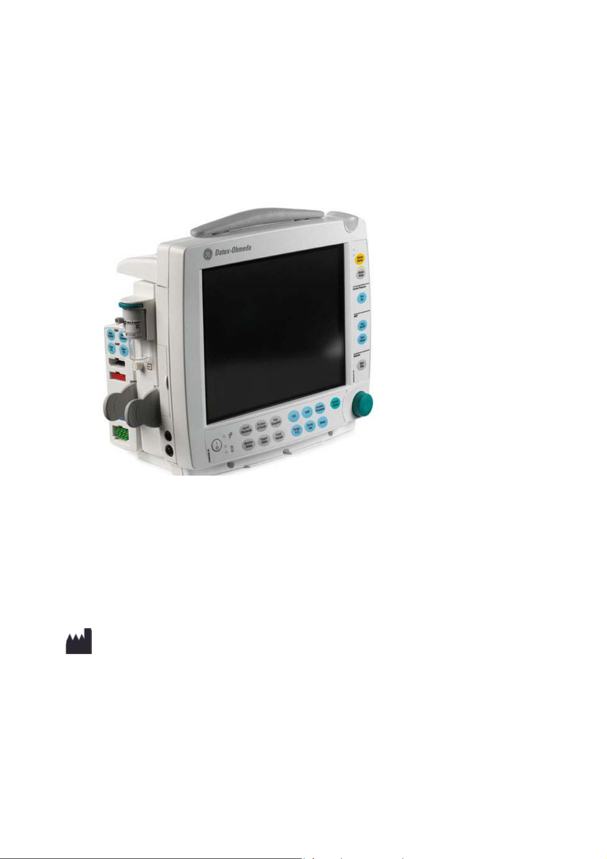
The Datex-Ohmeda S/5 FM is a modular multiparameter patient monitor. The monitor is
especially designed for monitoring in intensive care units. It can also be used during
transportation within the hospital.
The modular design makes the system flexible and easy to upgrade. In addition to patient
parameter modularity and easy upgrades, the monitor can be upgraded to wireless
networking. External devices can be interfaced to the monitor with interface modules.
NOTE: Your system may not include all these components. Consult your local representative for
the available components.
Introduction
Figure 1 S/5 FM with N-FCREC (1) and E-PSM (2) modules
1.0.1 Compatibility
S/5 FM is compatible with:
S/5 L-FICU04/A S/5 L-FICU06/A
Patient Side Modules,
S/5 E-PSM and E-PSMP
Extension Module S/5 F-FC x x
Extension Modules,
S/5 N-FCREC, and N-FREC
Device Interfacing Solution
S/5 N-DISxxx, rev. 01 and later
S/5 Network and iCentral x x
Wireless LAN is available with
WLAN option F-FMW
xx
xx
xx
xx
Document no. M1187317-009
3
Page 12
Datex-Ohmeda S/5 FM
Pb
Pb/Cd/Hg
1.1 Symbols
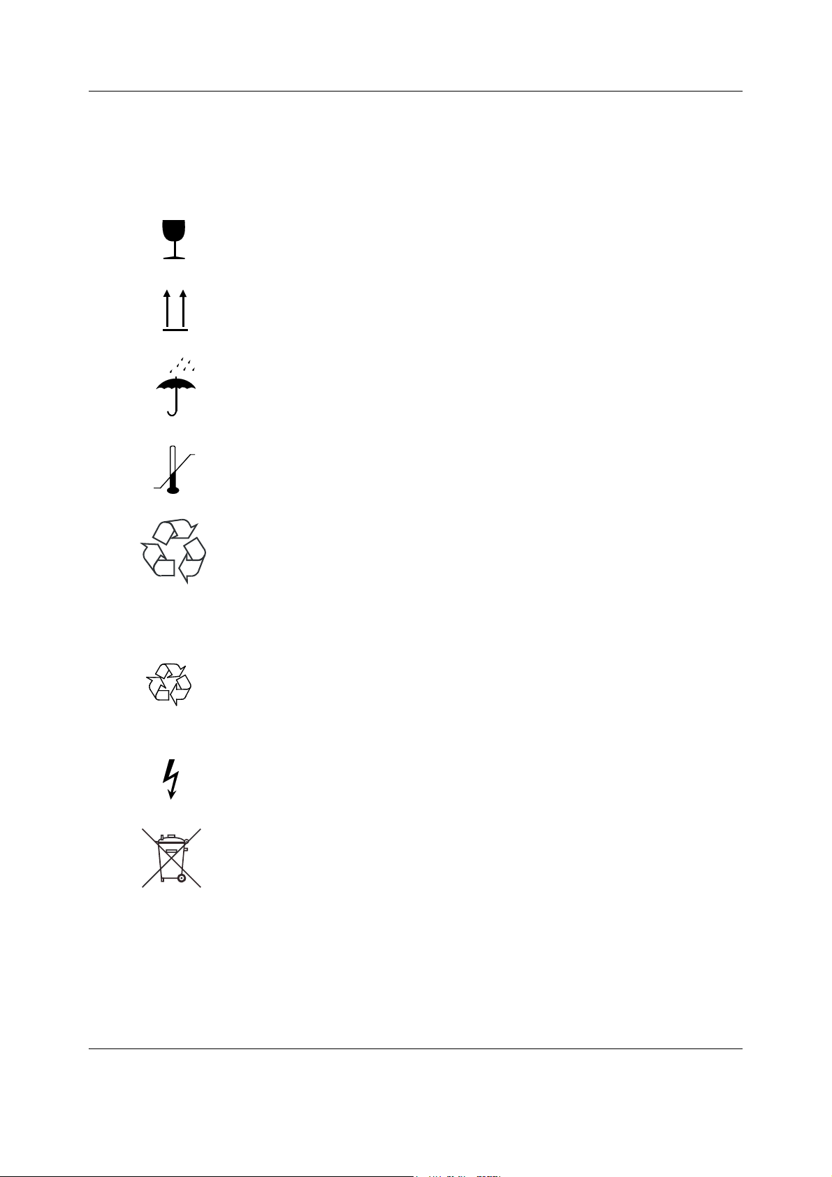
1.1.1 Symbols on transport packaging
The contents of the transport package are fragile and must be handled with
care.
Indicates the correct upright position of the transport package.
The transport package must be kept in a dry environment.
Indicates the temperature limitations within which the transport package
should be stored.
This package can be recycled.
1.1.2 Symbols on equipment
This battery contains lead and can be recycled.
Dangerous voltage.
The separate collection symbol is affixed to a battery, or its packaging, to advise
you that the battery must be recycled or disposed of in accordance with local or
country laws. The letters below the separate collection symbol indicate whether
certain elements (Pb=Lead, Cd=Cadmium, Hg=Mercury) are contained in the
battery. To minimize potential effects on the environment and human health, it is
important that all marked batteries that you remove from the product are properly
recycled or disposed. For information on how the battery may be safely removed
from the device, please consult the technical or service manual, or equipment
instructions. Information on the potential effects on the environment and human
health of the substances used in batteries is available at this url:
http://www.gehealthcare.com/euen/weee-recycling/index.html
4
Document no. M1187317-009
Page 13

1.1.3 Equipment safety symbols
- Attention, consult accompanying documents.
- When displayed next to the HR value, indicates that the pacer is set on R.
- On the N-FC(REC) module indicates that the airway gases should be
calibrated every 6 months in normal use and every two months in
continuous use to ensure that the measurement accuracy remains within
specifications.
- On the E-PSM(P) module:
WARNING Protection against cardiac defibrillator discharge is
- On the rear or bottom panel:
WARNING Electric shock hazard. Do not open the cover or the
WARNING Do not touch the monitor during defibrillation
WARNING Disconnect from the power supply before servicing.
WARNING When using the monitor with mounting attached,
CAUTION For continued protection against fire hazard, replace the
CAUTION Lithium battery on the CPU board. Dispose of the battery
Introduction
due in part to the accessories for pulse oximetry
(SpO
), temperature (T) and invasive pressure (P)
2
measurement.
back. Refer servicing to qualified service personnel.
procedure.
make sure that the mounting is manufacturer
approved.
fuse only with one of the same type and rating.
in accordance with local environmental and waste
disposal regulations.
- On top of the monitor beside the battery cover:
WARNING Use manufacturer recommended batteries only.
Dispose of the batteries in accordance with local
environmental and waste disposal regulations.
Type BF (IEC 60601-1) protection against electric shock.
Type BF (IEC 60601-1) defibrillator-proof protection against electric shock.
Type CF (IEC 60601-1) protection against electric shock.
Document no. M1187317-009
5
Page 14
Datex-Ohmeda S/5 FM
B
B
A
B
B
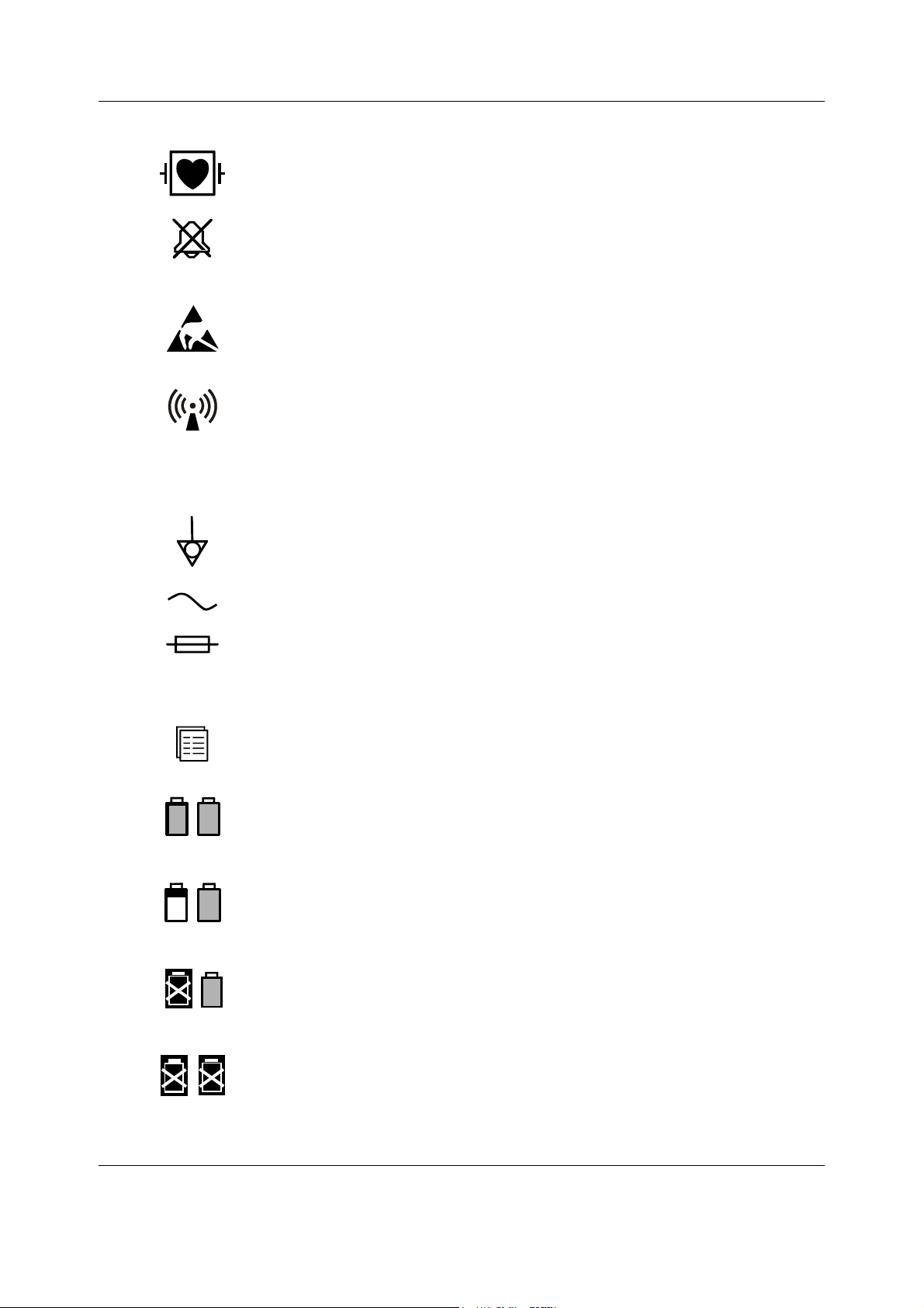
1.1.4 Other symbols
Type CF (IEC 60601-1) defibrillator-proof protection against electric shock.
When displayed in the upper left corner of the screen, indicates that the alarms
are silenced. When displayed in the menu or digit fields, indicates that the alarm
source has been turned off or alarm does not meet the alarm-specific activation
criteria.
ESD warning symbol for electrostatic sensitive devices. Pins of connectors
identified with the ESD warning symbol should not be touched. Connections
should not be made to these connectors unless ESD precautionary procedures
are used. For details, see section “1.2.2. ESD precautionary procedures”.
Symbol for non-ionizing electromagnetic radiation. Interference may occur in
the vicinity of equipment marked with this symbol.
SN, S/N
Equipotentiality. Monitor can be connected to potential equalization
conductor.
Alternating current
Fuse. Replace the fuse only with one of the same type and rating.
Serial Number
Submenu. Selecting an alternative marked with this symbol in a menu opens a
new menu.
Battery operation and remaining capacity. The height of the green bar
indicates the charging level.
Battery (A) charging (white bar)
Battery (A) failure
Both batteries have failed
6
Document no. M1187317-009
Page 15
Introduction
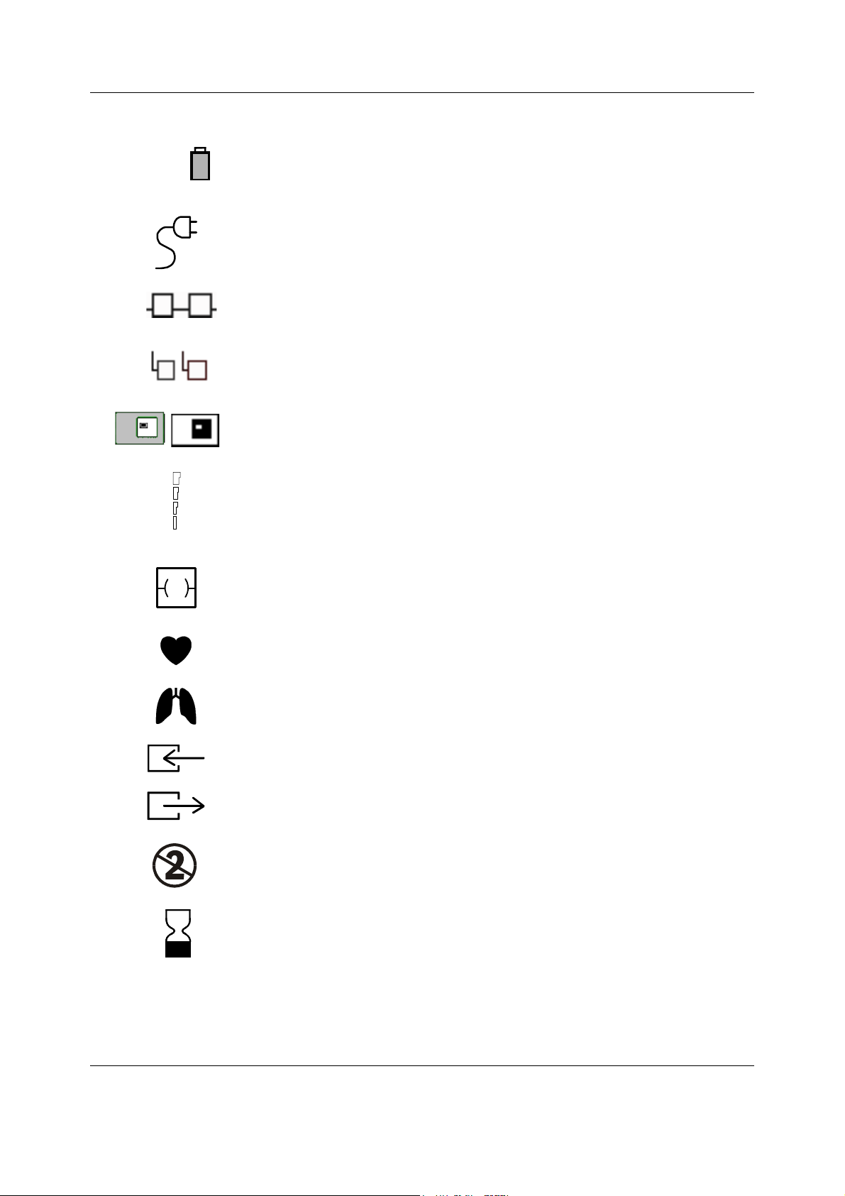
B
Battery (A) is missing
In the front panel: mains or external DC power. (External DC power for future
use.)
The monitor is connected to the Datex-Ohmeda Network (Local Area Network,
LAN).
The monitor is connected to the Datex-Ohmeda S/5 Network (Wireless Local
Area Network, WLAN).
Data Card (green) or Menu Card (white) is inserted.
WLAN signal strength. The number of segments corresponds to the signal
strength: four segments indicate strong signal, one segment weak signal.
When connection to access point is being searched, the segments scroll from
zero to four and back.
Ethernet connector
A blinking heart next to the heart rate or pulse rate value indicates the beats
detected.
A lung next to the respiration rate value indicates that respiration rate is
calculated from the impedance respiration measurement.
Gas inlet
Gas outlet
Do not reuse.
Use by. Indicates the last use day.
7
Document no. M1187317-009
Page 16
Datex-Ohmeda S/5 FM
Date of manufacturer
Manufacturer name and address
Does not contain Latex.
Do not immerse the sensor in liquids.
IPX class:
IPX0
IPX1
IPX2
IPX3
IPX4
IPX7
IPX8
Degree of protection against harmful ingress of water as detailed in the
IEC 60529:
- Ordinary equipment
- Protection against vertically falling water drops.
- Protection against vertically falling water drops when enclosure tilted
up to 15 °.
- Protected against spraying water.
- Protected against splashing water.
- Protected against the effects of temporary immersion in water.
- Protected against the effects of continuous immersion in water.
This symbol indicates that the waste of electrical and electronic equipment
must not be disposed as unsorted municipal waste and must be collected
separately. Please contact an authorized representative of the manufacturer
for information concerning the decommissioning of your equipment.
8
Document no. M1187317-009
Page 17

Introduction
1.2 Safety
The following list contains general warnings and cautions you should know before installing,
maintaining or servicing the system. Warnings and cautions specific to the use of the system
can be found in the User’s Guide and User’s Reference Manual.
1.2.1 Safety precautions
Warnings
WARNING A WARNING indicates a situation in which the user or the patient may be in
danger of injury or death.
• The device is not able to withstand unpacked drops from a height of 1 m. If the device is
dropped, please service the device before taking it back into use.
Power connection
• Always check that the power cord and plug are intact and undamaged.
• Do not use the power cord delivered with this product for any other product or purpose.
• Use only hospital-grade grounded power outlets and power cord. Do not remove the
grounding pin from the power plug.
• Use only an intact and undamaged power cord. Replace the power cord if it is cracked,
frayed, broken or otherwise damaged.
• All system devices must be connected to the same power supply circuit.
• Do not apply tension to the power cord otherwise the cord may get damaged.
• Do not use an additional multiple socket outlet, extension cord or adapters of any kind.
• Before starting to use the system, ensure that the whole combination complies with the
international standard IEC 60601-1-1 and with the requirements of the local authorities.
Do not connect any external devices to the system other than those specified.
• When detaching modules, be careful not to drop them. Always support with one hand
while pulling out with the other.
• If the integrity of the external protective earth conductor arrangement is in doubt, use the
monitor with battery operation.
• To avoid the risk of electric shock, this equipment must only be connected to a supply
mains with protective earth.
Installation
• Do not incinerate a battery or store at high temperatures as it will explode.
• The monitor or its components should not be used adjacent to or stacked with other
equipment. If adjacent or stacked use is necessary, the monitor and its components
should be observed to verify normal operation in the configuration in which it will be
used.
• Pins of connectors identified with the ESD warning symbol should not be touched.
Connections should not be made to these connectors unless ESD precautionary
procedures are used. For details, see section “1.2.2. ESD precautionary procedures.”
• After transferring or reinstalling the monitor, always check that it is properly connected
and all parts are securely attached. Pay special attention to this in case of stacked
mounting.
Document no. M1187317-009
9
Page 18

Datex-Ohmeda S/5 FM
• Do not use the monitor in high electromagnetic fields (for example, during MRI.)
• A printer or computer must be supplied from an additional transformer providing at least
• If you accidentally drop the monitor, modules or frames, have them checked by
• To avoid explosion hazard, do not use the monitor in presence of flammable anesthetics.
• Do not touch the patient, table, instruments, modules or the monitor during defibrillation.
• Other transmitting radio devices using the same radio frequency band (Industrial
External connection
• Do not connect any external devices to the monitor other than those specified.
Explosion hazard
• To avoid explosion hazard do not use the monitor in the presence of flammable
• Do not incinerate a battery or store at high temperatures as it will explode.
basic isolation (isolating or separating transformer).
authorized service personnel prior to clinical use.
Scientific and Medical 2.45 GHz band) may degrade or disturb the wireless network
communication.
anesthetics.
Patient safety
• Do not perform any testing or maintenance on the monitor while it is being used on a
patient.
• PACEMAKER PATIENTS: The impedance respiration measurement may cause rate
changes in Minute Ventilation Rate Responsive Pacemakers. In this case, set the
pacemaker rate responsive mode off or turn the monitor impedance respiration
measurement off.
• Never install the monitor so that it is above the patient.
• When using the monitor with mounting attached, make sure that the mounting is
manufacturer approved.
• Operation of the monitor outside the specified values may cause inaccurate results.
Autoclaving and sterilizing
• Do not autoclave any part of the system with steam or sterilize with ethylene oxide.
Cleaning and service
• Only trained personnel with proper tools and test equipment should perform the tests
and repairs described in this manual. Unauthorized service may void the monitor
warranty.
• Always unplug the monitor before cleaning or service. After cleaning or service ensure
that every part of the monitor is dry before reconnecting it to the power supply.
• Do not touch any exposed wire or conductive surface while any cover is removed and the
monitor is energized. The voltages present can cause injury or death.
• Pins of connectors identified with the ESD warning symbol should not be touched.
Connections should not be made to these connectors unless ESD precautionary
procedures are used. For details, see section “1.2.2. ESD precautionary procedures”.
• NOTE! The monitor is always internally powered when the batteries are connected.
10
Document no. M1187317-009
Page 19

Introduction
• Electrostatic discharge through the PC boards may damage the components. Before
handling PC boards, wear a grounded antistatic wristband. Handle all PC boards by their
non-conductive edges and use antistatic containers when transporting them.
• Do not break or bypass the patient isolation barrier when testing PC boards.
• Always perform an electrical safety check and a leakage current test on the monitor after
service.
• Handle the water trap and its contents as you would any body fluid. Infectious hazard
may be present.
• Do not immerse any part of the device in any liquid, or allow liquid to enter the monitor or
modules.
• If liquid has accidentally entered the system or its parts, disconnect the power cord from
the power supply, remove the batteries from the monitor and have the equipment
serviced by authorized service personnel.
• Since calibration gas contains anesthetic agents, always ensure sufficient ventilation of
the room during calibration.
Accessories
• Use only accessories, including mounts, and batteries, and defibrillator-proof cables and
invasive pressure transducers approved by GE Healthcare. For a list of approved supplies
and accessories, see the “Supplies and Accessories” catalog. Other cables, batteries,
transducers and accessories may cause a safety hazard, damage the equipment or the
system, result in increased emissions or decreased immunity of the equipment or system
or interfere with the measurement. (Protection against cardiac defibrillator discharge is
due in part to the accessories for pulse oximetry (SpO2), temperature (T) and invasive
pressure (P) measurement.)
• Single-use products are not designed to be reused. Reuse may cause a risk of
cross-contamination, affect the measurement accuracy and/or system performance, or
cause a malfunction as a result of the product being physically damaged due to cleaning,
disinfection, re-sterilization and/or reuse.
Special components
Special components are used in these monitors that are vital to assure reliability and safety. GE
Healthcare assumes no responsibility for damage, if replacement components not approved
by GE Healthcare are used.
Batteries
The Lithium Ion batteries are recyclable. Follow your local recycling guidelines.
Refresh the batteries completely every six months.
To replace the batteries safely, please refer to the service instructions in this manual.
• Do not short-circuit the battery terminals, this may produce a very high current, which will
damage the battery.
• Do not dispose of the battery into open flame, nor put the battery near fire, as it may
explode.
• Do not dismantle the battery.
• After replacing a battery, always make sure to close the battery compartment by sliding
the lid back to the right until it clicks.
See also section “Symbols”.
11
Document no. M1187317-009
Page 20

Datex-Ohmeda S/5 FM
Storage and transport
Do not store or transport the monitor outside the specified temperature, pressure and humidity
ranges:
Temperature -20...+60 °C/-4...140 °F
Atmospheric pressure 670...1060 hPa/500...800 mmHg/670...1060 mbar
Relative humidity 10...90% noncondensing
Disposal
• Dispose of the whole device, parts of it and its packing material and manuals in
accordance with local environmental and waste disposal regulations.
• Dispose the calibration gas container in accordance with local environmental and waste
disposal regulations.
Cautions
CAUTION A CAUTION indicates a condition that may lead to equipment damage or
malfunction.
Installation
• Leave space for air circulation to prevent the monitor from overheating.
• Before connecting the power cord to the power supply, check that the local voltage and
frequency correspond with the rating stated on the device plate.
• Turn off the power before making any rear panel connections.
Before use
• Allow two minutes for warm-up and note any error messages or deviations from normal
operation.
Fuse replacement
Replace a fuse only with one of the same type and rating.
Cleaning and service
• Do not use hypochlorite-, acetone-, phenol- or ammonia -based cleaners, abrasive
material or harsh chemicals as they may damage the surfaces of the device.
• Do not use abrasive cleaning compounds, instruments, brushes or rough-surface
materials.
• Do not apply pressurized air to any outlet or tubing connected to the monitor.
Special components
• Lithium battery on the CPU board. Dispose of the battery in accordance with local
environmental and waste disposal regulations.
12
Document no. M1187317-009
Page 21

1.2.2 ESD precautionary procedures
•
To avoid electrostatic charges building up, it is recommended to store, maintain and use
the equipment at a relative humidity of 30% or greater. Floors should be covered by ESD
dissipative carpets or similar. Non-synthetic clothing should be used when working with
the component.
• To prevent applying a possible electrostatic discharge to the ESD sensitive parts of the
equipment, one should touch the metallic frame of the component or a large metal object
located close to the equipment. When working with the equipment and specifically when
the ESD sensitive parts of the equipment may be touched, a grounded antistatic
wristband intended for use with ESD sensitive equipment should be worn. Refer to the
documentation provided with the wristbands for details of proper use.
ESD precautionary procedure training
It is recommended that all potential users receive an explanation of the ESD warning symbol
and training in ESD precautionary procedures.
The minimum contents of an ESD precautionary procedure training should include an
introduction to the physics of electrostatic charge, the voltage levels that can occur in normal
practice and the damage that can be done to electronic components if they are touched by an
operator who is electrostatically charged. Further, an explanation should be given of methods
to prevent build-up of electrostatic charge and how and why to discharge one’s body to earth
or to the frame of the equipment or bond oneself by means of a wristband to the equipment or
the earth prior to making a connection.
Introduction
13
Document no. M1187317-009
Page 22
Datex-Ohmeda S/5 FM
486
Processor
P
CMCIA
Serial Ether
net
Sound UPI
Chip
set
Displ
ay
Controller
486 LOCAL BUS
ISA-BUS
DRAM
Reset
Logic
Non-
Volatile
Memory
Boot
Memory
Code
Memory
Patient
Modules
Fm_p1_gnrl_bus_strctr_cm.vsd
MODULE-BUS
2 System description
2.1 Introduction
Datex-Ohmeda monitors build up a freely configurable modular system. The architecture is
designed to enable different module combinations so that the user is able to get the desirable
parameter and feature set. This modular approach makes it possible to add new features
when they are needed.
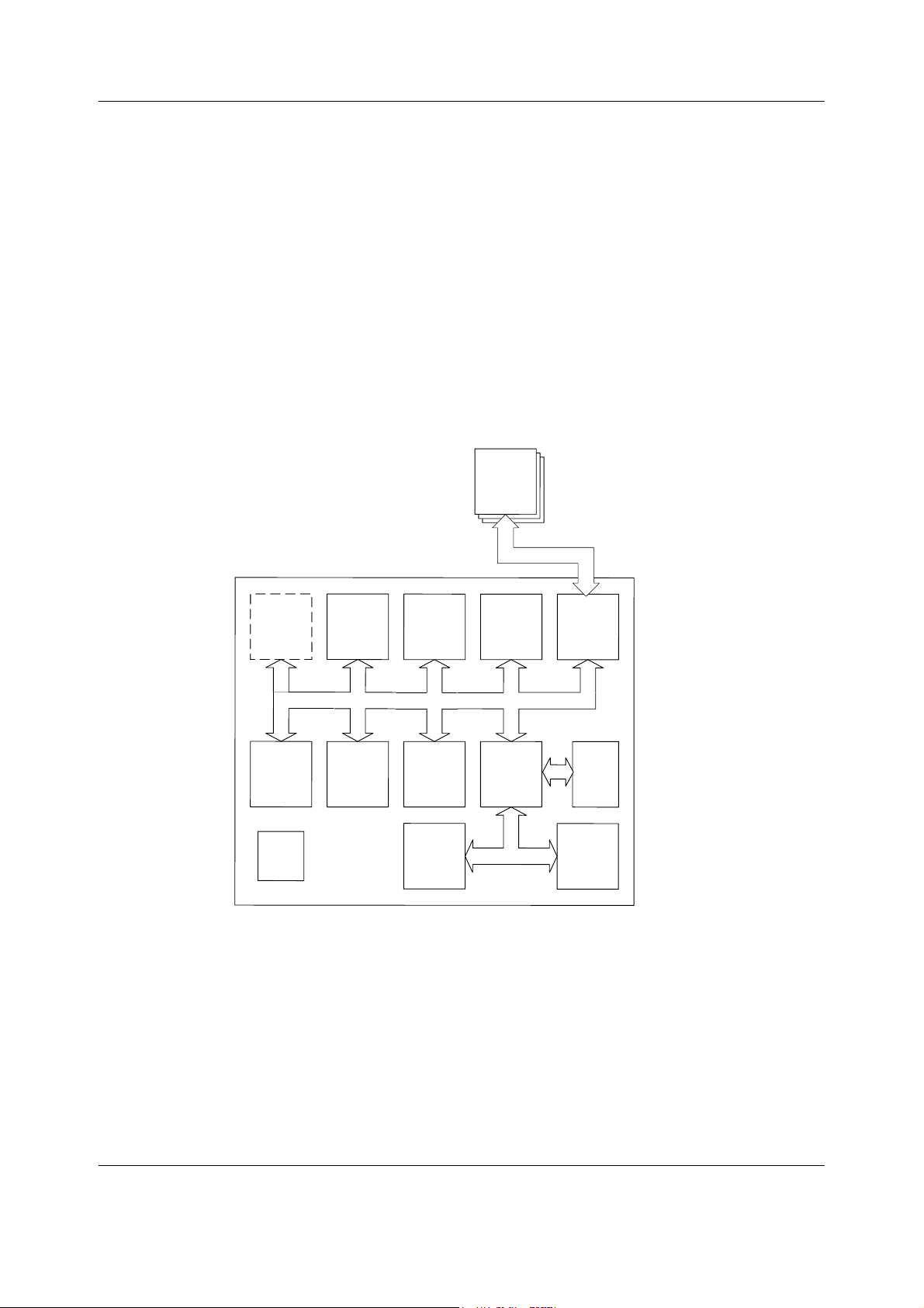
2.2 Bus structure
The operation of Datex-Ohmeda FM is based on two communication channels, the CPU bus
and module bus. All units, including the modules, receive power from the same power supply,
which is an integral part of the monitor frame.
Figure 2 General bus structure of S/5 FM
The CPU bus is a communication channel used only for internal data transfer. It is based on the
ISA bus used in IBM PC computers. Data is transferred on this 16 bit wide bus using the CPU
14
Document no. M1187317-009
clock frequency.
The module bus is for the parameter modules. The bus is based on the industry standard
RS-485, which uses a differential serial method to transfer data. This type of bus is robust and it
allows parameter modules to be inserted or removed while the power is on. The module bus
uses a 500 kbps data transfer rate.
Page 23

The RS-485 type of serial communication supports so-called multidrop or party line
UPI
Processor
Shared
SRAM
Control
Logic
ISA-BUS
Voltage
Meas
Temp
Meas
Keypad Interface
ComWheel I nterface
Module Bus
Analog & Digit al outputs
cam_p1_prncpl_UPI_operation.vsd
connections. This means that all parameter modules connected to the module bus use exactly
the same lines for communication. The advantage of this is that all bus connectors are
identical and the modules can be connected in any order and position.
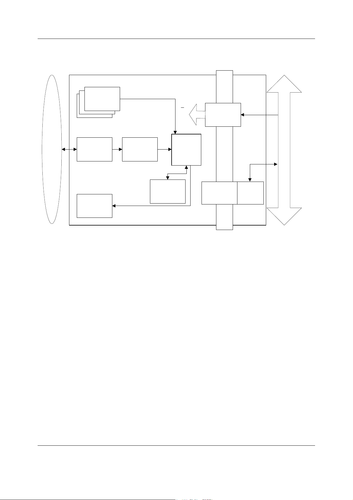
2.3 Distributed processing
A system assembled from Datex-Ohmeda products is a multiprocessor system. All parameter
modules have their own microprocessor, which performs functions such as module key
control, waveform filtering, parameter related computing and pneumatic control, etc. At the
same time the main CPU performs higher level tasks such as trending and alarm control. While
the parameter modules and CPU are performing their tasks, the UPI (Universal Peripheral
Interface) microprocessor handles all functions needed to transfer data between the
parameter modules and the CPU.
This kind of parallel processing gives one major advantage to centralized processing. When
new parameter modules are added to the system, the processing power is increased. As a
result, the system does not slow down when new features are added.
2.4 Module communication
The communication master controlling data transfers between the CPU and parameter
modules is called UPI processor. It sends data to each connected module 100 times a second.
Modules respond to each data request immediately by sending a data package, whose length
depends on the type of the module. This communication protocol ensures that each module
receives and sends data every 10 ms. If a module does not respond to data requests, the UPI
processor presumes that the module is disconnected.
Parameter modules may hold a static (fixed) or dynamic address, which the UPI processor uses
when sending out data. Two parameter modules of the same type must not be fitted onto the
same monitor since they might reply to a data request simultaneously, thus causing
communication errors.
System description
Figure 3 Principle of UPI section operation
15
Document no. M1187317-009
Page 24

Datex-Ohmeda S/5 FM
The UPI processor collects and stores all data that is received from the parameter modules into
a shared SRAM, which is mapped directly to the address space of the main CPU. The main CPU
reads data from the memory while the UPI processor guarantees that the data is up to date.
This operation also works in the other direction. In this the main CPU fills the shared SRAM with
data and the UPI processor distributes it to the parameter modules.
2.5 Software loading
The program memory on the CPU board is loaded with monitor software at the factory. The
software is used for running all the functions that are integrated into the PC board.
F-FM(W)-00
For service and upgrade procedures, the software loading is done by using a PCMCIA card or
the SWDL Tool.
F-FM(W)-01
For service and upgrade procedures, the software loading is done by using the SWDL Tool only.
16
Document no. M1187317-009
Page 25
2.6 Parameter modules
Module Bus
Isolation
transformer
RS485
drivers
Peripheral
drivers
A/D
converter
CPU
Analog
electronics
Opto
isolation
RAM
EEPROM
Patient isolation
PATIENT
Module
keys
Data
+13...16 V
VMOD
+5 V
+12 V
System description
Figure 4 General structure of parameter modules with patient isolation
The detailed structure of a parameter module depends on the specific needs for each
individual parameter. However, some common parts are used in the parameter modules. The
electronics inside the module is usually divided into isolated (floating) and non-isolated
sections. Typically, the non-isolated section consists of buffers to interface the parameter
module to the module bus while the rest of the electronics is located in the isolated section. The
isolated section includes the microcontroller together with memory components, the front-end
analog electronics (amplifiers, etc.) and sensor drivers.
17
Document no. M1187317-009
Page 26

Datex-Ohmeda S/5 FM
3 System installation
3.1 Unpacking instructions
1. Confirm that the packing box is undamaged. If the box is damaged, contact the shipper.
2. Open the top of the box and carefully unpack all components.
3. Confirm that all components are undamaged. If any of the components is damaged,
contact the shipper.
4. Confirm that all components are included. If any of the components is missing, contact
your GE Healthcare distributor.
3.2 Choosing location
Consider the following aspects:
• lighting
• space
• connections
• electromagnetic and radio frequency interference. For details see Appendix B.
ElectroMagnetic Compatibility
• environment
WARNING The monitor or its components should not be used adjacent to or stacked
with other equipment. If adjacent or stacked use is necessary, the monitor
and its components should be observed to verify normal operation in the
configuration in which it will be used.
CAUTION The monitor display is fragile. Ensure that it is not placed near a heat source or
exposed to mechanical shocks, pressure, moisture or direct sunlight.
3.3 Mounting the S/5 FM
Mounting of S/5 FM to the Wall Mount, Rollstand, Wall Mount with standard arm or Counter Top
Mount is described in a separate instruction sheet delivered with each mount.
WARNING After transferring or reinstalling the monitor, always check that it is
properly connected and all parts are securely attached. Pay special
attention to this in case of stacked mounting.
WARNING The monitor must not be used without a manufacturer approved mounting
attached.
WARNING Never install the monitor so that it is above the patient.
3.3.1 E-PSM(P) Mounting Accessories
Intended use
The Module Bus Adapter for PSM is intended for connecting the Pole Mount for PSM to the
Datex-Ohmeda S/5 FM monitor.
With Module Bus Adapter, the Pole Mount for PSM, short or long, can be connected to the
Datex-Ohmeda S/5 FM monitor. The E-PSM(P) module can be removed from the FM monitor
and docked to the Pole Mount for PSM, short or long.
18
Document no. M1187317-009
Page 27
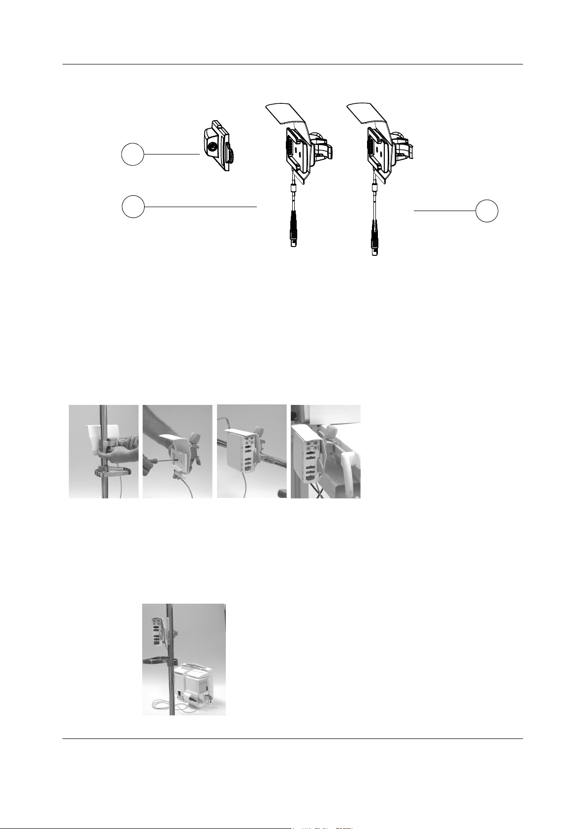
Figure 5 E-PSM(P) mounting accessories
2
1
3
1. M1051025 Module Bus Adapter for PSM
2. M1049197 Pole Mount for PSM, short
3. M1051023 Pole Mount for PSM, long
System installation
WARNING Make sure that the Pole Mount for PSM is always used in vertical position to
prevent water from entering the E-PSM(P) module.
Pole Mount for PSM – Instructions for connecting to an IV pole, vertical
position
Fasten the Pole Mount for PSM
with the fastening screw of the
clamp and tighten properly to an
IV pole.
Pole Mount for PSM - Instructions for installing in horizontal position.
Remove the 2 screws from the clamp, turn the clamp and insert and tighten the screws back.
Fasten the Pole Mount for PSM with the fastening screw of the clamp and tighten properly to a
horizontal tube or rail with a diameter of 10 mm*25 mm.
Pole mount for PSM – Instructions for connecting to monitor
1. Attach the E-PSM(P) module to the Pole Mount.
2. Connect the cable of the Pole Mount for PSM to the S/5 FM
monitor with the Module Bus adapter for PSM
(M1031025).
3. Check the module communication of the E-PSM(P)
module.
19
Document no. M1187317-009
Page 28
Datex-Ohmeda S/5 FM
1
14
12
11
2
3
5
4
6
7
9
10
13
8
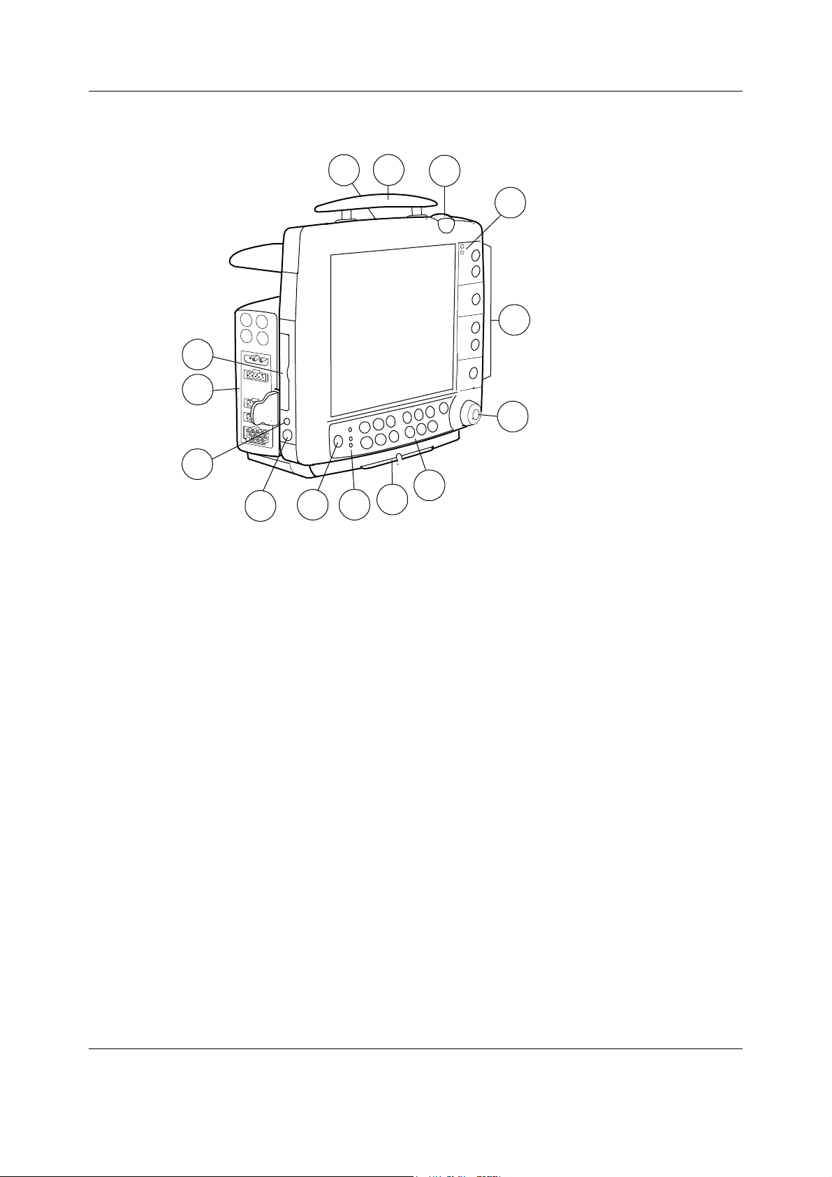
3.3.2 Monitor connections
Figure 6 S/5 FM front panel
(1) Battery compartment
(2) Transportation handle
(3) Alarm light
(4) Alarm LED indicators
(5) Side panel keys
(6) The ComWheel
(7) Command Board keys
(8) Guide rail for GCX mounting
(9) Mains power and battery LEDs
(10) ON/standby key
(11) Connector for the Device Interfacing Solution (X6)
(12) Connector for defibrillator synchronization (X5)
(13) Measurement modules
(14) Slot for Data Card or Menu Card
You can use one E-PSM(P) and/or one N-F(C)(REC) module in the monitor at a time.
20
Document no. M1187317-009
Page 29

System installation
4
1
2
8
3
7
6
5
10
13
14
12
Figure 7 Rear panel connections
(1) Slot for infusion pole mounting
(2) Module connector
(3) Guide rail for GCX mounting
(4) Receptacle for power cord
(5) Fuse holder
(6) Serial port X9
(7) Network ID X8
(8) Connector for K-CREMCO X7
(9) Optional: Multi I/O adapter incorporating connectors 6 - 8 mentioned above
(10) Network connector X1
(11) Equipotential connector
(12) Slot for Data Card or Menu Card
(13) Defibrillator & IABP sync connector X5
(14) Connector for the Device Interfacing Solution (X6)
Document no. M1187317-009
21
Page 30

Datex-Ohmeda S/5 FM
B
Battery charging
3.3.3 Connection to mains
Connect the power cord to the mains power inlet (4) at the back of the monitor and to the wall
socket.
NOTE: Before taking the monitor into use for the first time, the batteries should be fully charged.
Keep the monitor connected to the mains until the Battery charging symbol disappears, or in
STBY mode the Orange Battery condition LED is off (may take up to 5 hours if the batteries are
fully discharged).
WARNING The power cord may only be connected to a three-wire, grounded, hospital
grade receptacle.
3.3.4 Connection to Network
Use the Monitor-Network cable to connect the monitor to the network.
1. Make sure that the power is switched off.
2. Connect the Identification Plug and one RJ-45 connector to the connectors X8 and X1 at
the back of the monitor.
3. Connect the other RJ-45 connector to the corresponding connector on the wallbox.
4. Switch on the power. Confirm that the network connection is indicated in the upper
part of the screen.
3.3.5 Connection to Wireless Network
Wireless LAN is available only with S/5 FM Wireless LAN option F-FMW.
1. Disconnect the network cable.
2. The monitor will automatically connect to the Wireless LAN.
3. Confirm that the wireless LAN network symbol and the wireless LAN signal strength
symbol are displayed in the upper part of the screen.
NOTE: The WLAN configuration in the monitor has to be set to correspond to the hospital
WLAN.
22
Document no. M1187317-009
Page 31

System installation
1
2
3
1
3
0
s
e
c
2
3.3.6 Inserting and removing the parameter modules
1. Align the module with the insertion guides
2. Push the module into the monitor frame until it stops.
3. Pull the module outwards. Make sure not to drop it when it comes out.
WARNING When detaching modules, be careful not to drop them. Always support with
one hand while pulling out with the other.
NOTE: Only one E-PSM(P) module and one N-F(C)(REC) module can be attached to S/5 FM.
NOTE: If you want to install both modules, you must install the FM Extension Module,
(N-F(C)(REC) first and attach the E-PSM(P) module to it.
3.3.7 Downloading Monitor Software F-FM(W)-00
The following instructions apply to downloading of new monitor software in case of upgrade or
service. Detailed instructions for downloading software are supplied with software PCMCIA
cards.
NOTE: All user settings will be lost after downloading of new monitor software.
NOTE: During the downloading of software, the serial number of the monitor is written on the
software card. The software can then be downloaded again to the same monitor, but not to
any other monitor.
1. Make sure the monitor is switched to standby.
.
2. Open the cover for card drive slot. Insert the software card into the card drive slot and
press the software card firmly into its place.
23
Document no. M1187317-009
Page 32

Datex-Ohmeda S/5 FM
2
80
sec
5
3. Switch the monitor on.
4. Wait for approximately 80 seconds. After the normal screen appears, enter the service
5. Remove the software card.
6. Replace the original device plate for monitor software by the new one supplied with the
7. Perform Factory Reset. Make sure that the monitor functions normally after the restart.
8. Set the time and date (
9. Set the monitor’s network communication according to the used network software, if
The communication is set in the monitor’s Network service menu:
Monitor Setup - Install/Service (password 16-4-34) - Service (password 26-23-8) - Frame –
Network
Network software S-CNET01 -> DRI Level = 2001
Network software S-CNET02 -> DRI Level = 2001 or 2002 (WLAN)
Network software L-NET03 -> DRI Level = 2003
Network software L-NET05 -> DRI Level = 2003
NOTE: If the DRI level is changed, the monitor will restart automatically.
menu and make sure that the information regarding monitor software has been updated.
Memorize the serial number of new software.
software card.
Monitor Setup - Time And Date).
necessary.
10. Fill out all necessary documentation regarding the new monitor software.
NOTE: The license agreement of monitor software needs to be in accordance with the monitor
software serial number. Make sure you archive the license agreement in a secure location.
NOTE: The first start-up after software loading takes considerably longer.
3.3.8 Downloading Monitor Software, F-FM(W)-01
See “Software Download Tool - User Instructions.”
Software Download Tool, L-SWDL, is the only way to download/replace software on
F-FM(W)-01 frame by a field engineer. SWDL is a service tool that enables the installation of
monitor service software from personal computer into legacy Datex-Ohmeda patient monitor.
24
Document no. M1187317-009
Page 33

3.3.9 Performing Factory Reset
NOTE: The Factory Reset is necessary after downloading of monitor software and after
replacing the CPU board or SRAM/Timekeeper battery.
NOTE: The Factory Reset will restore all your customized defaults, including language selection,
to factory defaults.
System installation
1. Press the
2. Select Install/Service and password (16-4-34).
3. Select Service and password (26-23-8).
4. Select Set/Test and perform Factory Reset.
5. The monitor will perform an automatic restart. After the restart is completed, restart the
monitor also manually by the On/Standby switch.
Monitor Setup key.
3.3.10 Installing the Datex-Ohmeda Wireless Network Upgrade, U-FMW (F-FM-00)
The following instructions apply to upgrading the monitor with the Wireless Network Upgrade.
Detailed upgrade instructions are supplied with the corresponding product.
NOTE: You can download the option software only to one monitor. During the downloading of
the option software, the serial number of the monitor is written on the software card, and if the
downloading for some reason would fail, the software can be downloaded again.
1. Make sure that the monitor is switched to STANDBY.
2. Open the cover for the card drive slot (on the left side of the monitor). Insert the option
software card into the card drive slot and press the software card firmly in position.
3. Switch the monitor ON.
4. Wait until the normal screen appears and check that the message 'Field upgrade OK' is
displayed as a note of successful upgrade.
5. Remove the option software card.
6. Switch the monitor to STANDBY.
7. Disassemble the monitor in order to access the second PC card drive slot on the monitor
CPU board.
NOTE: Follow instructions in the S/5 Frame for FM slot for disassembling the monitor.
8. Insert the WLAN interface card into the PC card drive slot.
9. Connect the WLAN antennas to the handle guide.
Document no. M1187317-009
25
Page 34

Datex-Ohmeda S/5 FM
10. Connect the WLAN antennas to the WLAN interface card. Secure the antennas to the PC
11. Reassemble the monitor.
NOTE: When reassembling the monitor make sure that the tips of the WLAN halfwave antennas
do not get pinched between the monitor covers.
12. Switch the monitor ON.
13. Enter the service menu and make sure that the option software was downloaded
14. Enter the WLAN Configuration service menu (
card drive slot with the holder included in the upgrade kit.
successfully (
Options = ”WLAN”
Monitor Setup –Install/Service (16-4-34) – Service (26-23-8) – Frame):
Monitor Setup –Install/Service (16-4-34) –
Service (26-23-8) – Frame - Network – WLAN – WLAN Config).
Enter the appropriate Network ID, WEP Algorithm, Key ID and Encryption Key using the
corresponding menu selections.
For selecting allowed communication channels, enter the appropriate Channel Mask
using the corresponding menu selection.
See Appendix C. Channel Mask Selections for S/5 FM.
Save the monitor’s wireless LAN configuration by selecting Save Configuration - Save.
NOTE: The settings must match up with the ones that are defined in the Access Point
configuration. Refer to the related site configuration documentation for correct settings, if
necessary.
15. Attach the RLAN card sticker above the device plate at the monitor rear panel.
If the monitor is located in Czech Rebublic, Hong Kong, Poland, Singapore, Taiwan, South
Africa or South Korea, attach also the corresponding country sticker (delivered with the
WLAN interface card) to the place that is indicated with a dashed line on the RLAN card
sticker.
26
Document no. M1187317-009
Page 35

System installation
16. Enter the Network Status service menu (Monitor Setup –Install/Service (16-4-34) –
Service (26-23-8) – Frame - Network – Network Status).
Check that the Virtual ID sticker that is supplied with the Wireless Network upgrade,
U-FMW corresponds with the Location ID that is displayed in the menu.
NOTE: The Location ID is the monitor’s ID on the Datex-Ohmeda Network and cannot be
changed.
17. Attach the Virtual ID sticker above the RLAN card sticker at the monitor rear panel.
18. Configure the monitor’s Location ID in the S/5 Central Network setup.
NOTE: Refer to the Datex-Ohmeda S/5 Central, ViewStation and Network Technical Reference
Manual for information about the configuration, if necessary.
19. Check that the monitor connects to the Datex-Ohmeda Wireless Network:
- the wireless LAN network symbol is displayed on the monitor screen
- the S/5 Central is listed in the monitor’s Network Status service menu
- monitor data can be displayed on the S/5 Central
Wireless LAN network symbol on the S/5 FM monitor
20. Fill out all necessary documentation regarding the upgrade.
3.3.11 Installing the Datex-Ohmeda Wireless Network Service Option, N-FMWS (F-FM-00)
The following instructions apply to upgrading the monitor with the Wireless Network Service
Option. Detailed upgrade instructions are supplied with the corresponding product.
NOTE: You can download the option software only to one monitor. During the downloading of
the option software, the serial number of the monitor is written on the software card, and if the
downloading for some reason would fail, the software can be downloaded again.
1. Make sure that the monitor is switched to STANDBY.
2. Open the cover for the card drive slot (on the left side of the monitor). Insert the option
software card into the card drive slot and press the software card firmly in position.
3. Switch the monitor ON.
4. Wait until the normal screen appears and check that a message 'Field upgrade OK' is
displayed as a note of successful upgrade.
5. Remove the option software card.
6. Enter the service menu and make sure that the option software was downloaded
successfully (
Options = ”WLAN”
7. Enter the WLAN Configuration service menu (
Service (26-23-8) – Frame - Network – WLAN – WLAN Config).
Monitor Setup –Install/Service (16-4-34) – Service (26-23-8) – Frame):
Monitor Setup –Install/Service (16-4-34) –
Enter the appropriate Network ID, WEP Algorithm, Key ID and Encryption Key using the
corresponding menu selections.
For selecting allowed communication channels, enter the appropriate Channel Mask
using the corresponding menu selection.
27
Document no. M1187317-009
Page 36

Datex-Ohmeda S/5 FM
NOTE: The settings must match up with the ones that are defined in the Access Point
configuration. Refer to the related site configuration documentation for correct settings, if
necessary.
See Appendix C. Channel Mask Selections for S/5 FM.
Save the monitor’s wireless LAN configuration by selecting Save Configuration - Save.
8. Enter the Network Status service menu (
Monitor Setup –Install/Service (16-4-34) –
Service (26-23-8) – Frame - Network – Network Status).
Check that the Virtual ID -sticker that is supplied with the Wireless Network upgrade,
U-FMW corresponds with the Location ID that is displayed in the menu.
NOTE: The Location ID is the monitor’s ID on the
Datex-Ohmeda Network and cannot be
changed.
9. Attach the Virtual ID sticker above the RLAN card sticker at the monitor rear panel.
10. Configure the monitor’s Location ID in the S/5 Central Network setup.
NOTE: Refer to the Datex-Ohmeda S/5 Central, ViewStation and Network Technical Reference
Manual for information about the configuration, if necessary.
11. Check that the monitor connects to the Datex-Ohmeda Wireless Network:
- the wireless LAN network symbol is displayed on the monitor screen
- the S/5 Central is listed in the monitor’s Network Status service menu
- monitor data can be displayed on the S/5 Central
Wireless LAN network symbol on the S/5 FM monitor
12. Fill out all necessary documentation regarding the upgrade.
3.3.12 Installing the S/5 Wireless Network Upgrade, U-FMW-01
The following instructions apply to upgrading the monitor with the Wireless Network Upgrade.
Detailed upgrade instructions are supplied with the corresponding product.
1. Perform main software upload to the monitor using Software Download Tool.
NOTE: Follow Software Download Tool User Instructions, if necessary.
When generating the license key use N-FMW as an option.
Use the Virtual ID number that is supplied with the Wireless Network Upgrade,
U-FMW-01 package to avoid ID conflict in the network.
28
Document no. M1187317-009
Page 37

System installation
After the patient monitor has restarted for the first time after monitor software
reinstallation, perform a factory reset to the patient monitor.
2. Enter the service menu and make sure that the WLAN option was activated successfully
Monitor Setup -Install/Service (16-4-34) - Service (26-23-8) - Frame):
(
Options = "WLAN"
3. Switch the monitor to STANDBY.
4. Disassemble the monitor in order to access the Compact Flash card drive slot on the
monitor CPU board.
NOTE: Follow instructions in the S/5 Frame for FM slot for disassembling the monitor, if
necessary.
5. Insert the WLAN interface card into the Compact Flash card drive slot.
6. Connect the WLAN antennas to the handle guide.
7. Connect the WLAN antennas to the WLAN interface card. Secure the antennas to the
Compact Flash card drive slot with the holder included in the upgrade kit.
8. Reassemble the monitor.
NOTE: When reassembling the monitor make sure that the tips of the WLAN halfwave antennas
do not pinch between the monitor covers.
9. Switch the monitor ON.
29
Document no. M1187317-009
Page 38

Datex-Ohmeda S/5 FM
10. Enter the WLAN Configuration service menu (Monitor Setup -Install/Service (16-4-34) -
NOTE: The settings must match up with the ones that are defined in the Access Point
configuration. Refer to the related site configuration documentation for correct settings, if
necessary.
11. Attach the RLAN card sticker above the device plate at the monitor rear panel.
Service (26-23-8) - Frame - Network - WLAN - WLAN Config).
Enter the appropriate Network ID, WEP Algorithm, Key ID and Encryption Key using the
corresponding menu selections.
For selecting allowed communication channels, enter the appropriate Channel Mask
using the corresponding menu selection. See Appendix C. Channel Mask Selections for S/5
FM.
Save the monitor's wireless LAN configuration by selecting Save Configuration - Save.
If the monitor is located in Czech Rebublic, Hong Kong, Poland, Singapore, Taiwan, South
Africa or South Korea, attach also the corresponding country sticker (delivered with the
upgrade package) to the place that is indicated with a dashed line on the RLAN card
sticker.
12. Enter the Network Status service menu (
Service (26-23-8) - Frame - Network - Network Status).
Check that the Virtual ID -sticker that is supplied with the Wireless Network upgrade,
U-FMW corresponds with the Location ID that is displayed in the menu.
NOTE: The Location ID is the monitor's ID on the S/5 Network and cannot be changed.
13. Attach the Virtual ID -sticker above the RLAN card sticker at the monitor rear panel.
14. Configure the monitor's Location ID in the S/5 Central Network setup.
NOTE: Refer to the Datex-Ohmeda S/5 Central, ViewStation and Network Technical Reference
Manual for information about the configuration, if necessary.
15. Check that the monitor connects onto the S/5 Network wireless:
the wireless LAN network symbol is displayed on the monitor screen
the S/5 Central is listed in the monitor's Network Status service menu
monitor data can be displayed on the S/5 Central
Wireless LAN network symbol on the S/5 FM monitor
16. Fill out all necessary documentation regarding the upgrade.
Monitor Setup -Install/Service (16-4-34) -
30
Document no. M1187317-009
Page 39

3.4 Remote Controller, K-CREMCO
To connect a Remote Controller, K-CREMCO to S/5 FM plug the connector to the 5-pin DIN
connector X7 in Multi I/O adapter at the back of the monitor.
3.5 Visual indicators
Function Specification Explanation
External power supply Green LED Indicates when monitor is powered from
Battery operation Green LED Indicates when monitor is powered from
Battery condition Orange LED Indicates when monitor is charging
Alarm LEDs Red LED Indicates a life threatening situation
Yellow LED Indicates serious but not life threatening
Alarm Light Highly visible Red/
Yellow light Ease alarm detection from distance.
System installation
mains or ext. DC (External DC power for
future use)
internal batteries
batteries (solid) or battery failure, one or
both batteries missing (flashing).
problems
Brightness of the light and enabling the
alarm light function are user configurable.
3.6 Troubleshooting
If a problem occurs during the functional examination, check the components of the monitor
according to the following troubleshooting chart. If the problem persists, please refer to the
part II.
Problem What to do
Nothing functions Unplug and re-plug Remote Controller Cable. Also confirm that the cable is intact.
Unplug and re-plug the Power Cord. Also confirm that the cable is intact.
Confirm that the fuses are intact.
E-PSM(P) module does
not function
N-F(C)(REC) module does
not function
Remove and replace the module.
Confirm that the desired parameters are configured to be displayed.
Confirm that ‘Occlusion’ or ‘Calibrating Gas Sensor’ messages are not displayed.
Confirm that a D-fend water trap and a sample tube are attached.
Confirm that the desired parameters are configured to be displayed.
Remove and replace the module.
31
Document no. M1187317-009
Page 40

Datex-Ohmeda S/5 FM
4 Interfacing
External devices can be interfaced with the S/5 FM via the monitor's serial port and via the
Device Interfacing Solution, N-DISxxx.
Printers and computers can be interfaced via the monitor’s serial port.
Device specific N-DISxxx modules can be used with:
• Monitors
• Blood-gas analyzers
NOTE: The Device Interfacing Solution, N-DISxxx that is used on the S/5 FM must be of revision
01 or later.
4.1 Interfacing external bedside devices via Device Interfacing Solutions, N-DISxxx
The Device Interfacing Solution, N-DISxxx provides means for transferring physiological,
waveform and event data from various bedside patient care devices to the Datex-Ohmeda
monitoring system. The real-time and trended data can be displayed on the monitor screen
and used for record keeping purposes. The interfacing module reads the data coming from the
external device, converts it to a suitable format and sends it to the monitor.
See the following table of DIS modules and devices that you can interface with the Device
Interfacing Solution.
Table 4 DIS modules and interfaced devices
Device Monitors
N-DISOXIM3
N-DISQVUE
N-DISVIGIL
1 Trademark of Hospira Inc. (previously trademark of Abbott Laboratories)
2 Trademark of Edwards Lifesciences Corporation
Oximetrix 3
QVue /Q2
Baxter-Vigilance
1
1
2
Device Blood gas analyzers
N-DISOPT
1 Trademark of Osmetech plc
For specific information on parameters transferred from the interfaced device to the
Datex-Ohmeda monitor and the applicable software versions of the device refer to the
Installation guide accompanying each DIS module.
Osmetech Opti CCA
1
32
Document no. M1187317-009
Page 41

4.1.1 Device Interfacing Solution components
The Device Interfacing Solution consists of:
a device specific interfacing module
a device specific cable
a bus cable
a connector for another bus cable
label specifying the external device
4.1.2 Connections
Connect the device specific cable to the external device and the bus cable to the monitor's DIS
connector or to another interfacing module.
Interfacing
(1) label specifying the external device
(2) LED indicators
(3) black bus cable from another
interfacing module, if needed
(4) gray device specific cable to the
communication port of the external
device
(5) black bus cable to the monitor’s DIS
connector (or to another interfacing
module)
Figure 8 Connection cables and LED indicators
WARNING The monitor, interfacing modules and interfaced devices must be situated
in the same patient environment (as defined in IEC 60601-1-1).
WARNING Connecting electrical equipment together or using the same extension cord
for more than one device may cause their leakage currents to exceed the
limits specified in relevant safety standards. Always make sure that the
combination complies with the international safety standard IEC 60601-1-1
for medical electrical systems and with the requirements of local
authorities.
WARNING The manufacturer guarantees a reliable functioning of the devices with
tested software versions only. Always refer to the Installation guide
accompanying the DIS module and verify the compatibility before use.
33
Document no. M1187317-009
Page 42

Datex-Ohmeda S/5 FM
1
2
4
3
2
4.1.3 Mounting
The DIS module can be mounted on the side panel of the external device. Also IV pole
placement is possible.
NOTE: As the Device Interfacing Solution works only with the device specified in the label of the
interfacing module, it is recommended that the interfacing module always travels along with
the external device.
For mounting accessories, please refer to the “Supplies and Accessories” catalog. See the
following figure for an example of a device interfacing.
Figure 9 An example of interfacing external devices with Device Interfacing
Solution
(1) Datex-Ohmeda S/5 FM
(2) Interfacing module
(3) Monitor
(4) Blood gas analyzer
NOTE: Only N-DISxxx version 01 or later is compatible with the S/5 FM.
NOTE: You can connect up to four (4) interfacing modules to one system simultaneously.
Check the maximum number of modules: one meter cable = max. four ten modules, three
meter cable = max. three modules, six meter cable = one module.
WARNING Make sure that the interfacing module is always used in vertical position to
prevent water from entering the module.
WARNING Make sure that you are connecting the interfacing module to the device
specified in the label. Always verify the compatibility of the software
versions before use.
4.1.4 Selecting the external device
1. Turn off the monitor.
2. Turn off the external device.
3. Connect the interfacing module to the monitor’s connector for N-DIS or to another
interfacing module.
4. Connect the device specific cable to the external device and turn the external device on.
34
Document no. M1187317-009
5. Turn the monitor on. The monitor identifies the connected device automatically.
Page 43

4.1.5 Functional check
There are two ways to check the function of the Device Interfacing Solution:
1. Press the
2. Select Interfacing and open the Status Page menu. The status page shows you the
current communication status of the interfacing module (1 - 4).
NOTE: The status message ‘Connected’ appears on the Status Page after you have connected
the external device to the interfacing module and turned it on. Note also that the monitor and
the interfacing module must be operational.
• Check the LED indicators on the interfacing module (the green LED indicates physical
connections, the yellow LED software selections)
:
GREEN YELLOW INDICATION
Interfacing
Monitor Setup key.
lit dark
Physical connections between the monitor, interfacing
module and external device are in order and the device has
been selected in the menu.
dark
lit
There is something wrong with the physical connections
between the monitor, interfacing module and external
device. The external device has not been selected in the
menu.
lit lit
Physical connections between the monitor, interfacing
module and external device are in order but the external
device has not been selected in the menu.
dark dark
The interfacing module is not connected to the monitor.
4.1.6 Selecting the parameter data source
Select the external device via Monitor Setup - Interfacing menu:
• Select the desired measurement parameter (e.g., SvO
• Select the desired source by name (e.g., Oxim3).
NOTE: The name of the device is visible on the list only if the device is correctly connected.
NOTE: Detailed information about interfacing module related mountings, connections and
settings is included in the installation guides that are delivered with the interfacing modules.
).
2
35
Document no. M1187317-009
Page 44

Datex-Ohmeda S/5 FM
4.2 Interfacing printer
It is possible to interface a laser printer (serial or parallel) with the S/5 FM via the monitors’ serial
port. The printer should be PCL5 compatible and should contain at least 2 MB of memory.
Parallel printers require the use of Serial-to-Parallel Converter, order code 78030, model PI
130-R2.
WARNING Always make sure that the combination complies with the international
safety standard IEC 60601-1-1 for medical electrical systems and with the
requirements of local authorities.
WARNING Connecting the power supply cord of the printer to the wall power outlet
may cause the printer leakage current to exceed the limit specified for
medical equipment. A printer must be supplied from an additional
transformer providing at least basic isolation (isolating or separating
transformer).
4.2.1 Setting S/5 FM interface for printers
1. Press the Print/Record key.
2. Select Printer Connection.
3. Select Serial.
4. Press the
Normal Screen key.
4.2.2 Connection to serial printers
A serial printer is connected to the serial port connector X9 in the Multi I/O adapter at the back
of the frame unit.
Contact your authorized GE Healthcare distributor for advice on suitable serial printers.
4.2.3 Connection to parallel printers
A parallel printer is connected to the serial interface port connector X9 on the frame unit via the
Serial-to-Parallel Converter, order code 78030, model PI130-R2.
Contact your authorized GE Healthcare distributor for advice on suitable parallel printers.
4.2.4 Installing the Serial-to-Parallel Converter
Order code 78030, model PI130-R2
A common serial modem cable, gender changer and parallel printer cable are required when
connecting the serial to parallel converter between the monitor and a parallel printer. The
converter gets power from the connected devices.
1. Make sure that power is switched off on both devices.
2. Connect a standard PC-to-parallel-printer cable (order code 713701) to the parallel
printer.
36
Document no. M1187317-009
Page 45

Interfacing
Position
Flow Control:
hardware
LED: Enabled
Parity/D, Bits/S, Bit:
None/8/1
D.Rate (kbps):
115,2
1
OFF
2
ON
3
OFF4OFF
5
OFF
6
OFF7ON8OFF
DB9F end
plugs into FM
DB25M end
plugs into
Centronics
end plugs
plugs into
Standard Parallel Printer
plugs into FM
Serial to Parallel
Standard Async.Modem Cable
gender changer
Gender changer
into printer
DB25M end
plugs into
gender changer
converter
Converter
Gender changer
3. Check the DIP-switch settings on the converter (order code 78030, model PI130-R2):
4. Connect a DB25 female-to-female gender changer (order code 78032) between the
printer cable and converter.
Figure 10 Connecting S/5 FM monitor to printer, converter model PI130-R2
5. Connect a common RS-232 modem cable’s (order code 78031) DB9 connector to the
serial port connector X9 on the monitor, and the DB25 connector to the converter.
The new Serial to Parallel Converter, PI1115A, is not compatible with the FM monitor.
4.2.5 Connection to printer
Setting the printing parameters
Refer to the documentation provided with the printer.
4.3 Interfacing computer
A computer is connected to the serial port connector on the Multi I/O connector.
Contact your authorized GE Healthcare distributor for further advice on computer interface.
WARNING Always make sure that the combination complies with the international
safety standard IEC 60601-1-1 for medical electrical systems and with the
requirements of local authorities.
WARNING Connecting the power supply cord of the computer to the wall power outlet
may cause the computer leakage current to exceed the limit specified for
medical equipment. A computer must be supplied from an additional
transformer providing at least basic isolation (isolating or separating
transformer).
37
Document no. M1187317-009
Page 46

Datex-Ohmeda S/5 FM
5
9
1
6
4.4 Output signals
Analog/digital output signals on the connectors X5 and X8 can be used for interface with other
devices. The pin assignments are illustrated in tables/pictures below.
Table 5 NET ID connector, X8 on Multi I/O adapter
9 pin female D-connector Pin Signal
Table 6 Defib & IABP sync connector, X5
Mini DIN7 connector Pin Signal
4.4.1 Digital outputs
1
2
3
4
5
6
7
8
9
1
2
3
5
6
7
8
NET_ID_CS (chip delect)
NET_ID_CLK (clock)
NET_ID_DO (data out)
NET_ID_DI (data in)
GND
+5V_out
GND
Nurse call
GND
Defib_sync_out
Reserved
Analog GND
Digital GND
Reserved
Pressure_out
Direct_ECG_out
The digital output signals are as follows:
Defibrillation Sync (X5 pin 1)
Defibrillation Sync indication is generated by ECG. When active, the signal is state 1. After 10
ms the signal is reset to state 0. New Defibrillation Sync is not generated before the indication is
deactivated. The delay from the R wave peak to the start of the signal is maximally 35 ms.
Nurse Call (X8 pin 8)
Nurse Call indication is generated by red and yellow alarms. When activated, it is set to state 1
and remains at that state until the alarm situation is over or
The range of state 0 is from 0 to 0.5 V, and range of the state 1 is from 3.5 to 5 V.
4.4.2 Analog outputs
S/5 FM produces two analog real-time signals. The Direct ECG signal is available in Defib&IABP
sync connector X5 pin 8. The other signal is Invasive pressure output. It is available in
Synchronization connector X5 pin 7.
NOTE: When source of the selected analog output is invalid (e.g. invasive pressure channel is
not zeroed), or becomes invalid (e.g. ECG lead is disconnected), the signal on the output is
shown as flat line (0 VDC).
38
Document no. M1187317-009
SILENCE ALARM key is pressed.
Page 47

Interfacing
The pacemaker pulses have been replaced with 2 ms/5 V fixed digital pulses at the ECG analog
output for IABP or defibrillator equipment. A device that fulfils the requirements of the IEC
60601-1 standard can be connected to the defibrillator & IABP synchronization connector.
There are no other limitations, because the signals of the connector are galvanically isolated
from patient applied part of the ECG and invasive blood pressure measurements.
Direct ECG (X5 pin 8)
From first user lead (ECG1)
Gain: 1 V/1mV ±20%
Delay: < 15 ms
DC offset: ±100 mV max.
Output range: ±4 V
Noise: 50 mVpp max.
Frequency response: 0.05 Hz to 40 Hz
The signal requires input impedance of 100 k
Pressure out (X5 pin 7)
Invasive pressure signal: From pressure channel P1
Gain: 10 mV/1 mmHg ±20%
Delay: < 35 ms
DC offset: ±100 mV
Output range: -0.4 V to +3.2 V
Noise: 50 mVpp max.
The signal requires input impedance of 100 k
39
Document no. M1187317-009
Page 48

Datex-Ohmeda S/5 FM
5 Functional check
These instructions include procedures for a functional check for Datex-Ohmeda S/5 FM. The
functional check is mandatory after monitor installation.
These instructions include a “Functional check form, Datex-Ohmeda S/5 FM” which may be
used when performing the procedures. The symbol
check form contains space to record the results of the particular procedure. The procedures
should be performed in ascending order, bypassing those that are not applicable for a
particular monitor.
All menu selections related to Datex-Ohmeda products are written in following typeface:
e.g. Parameters - Gas Unit.
As you enter the service menus, you need the following passwords:
Monitor Setup - Install/Service (password 16-4-34) - Service (password 26-23-8)
In case you evaluate the measurement accuracy with a patient simulator, add simulator’s
accuracy specification to the one of the monitor.
An electrical safety check and a leakage current test are recommended to be performed prior
to the monitor installation.
in the instructions indicates that the
40
Document no. M1187317-009
Page 49

5.1 Recommended tools
NOTE: Use only properly maintained, calibrated and traceable measurement equipment for the
specified calibrations and adjustments to ensure accuracy.
For product(s) Tool Order No.
Airway modules
N-FC(REC) Calibration gas 755580
Regulator 755534-HEL
Functional check
N-FC(REC) CO
Sampling line 3m/10 ft 733163
2
Hemodynamic modules
Multi-Link ECG accessories, IEC
E-PSM(P)
- Multi-link 3-leadwire set 412682-003
- Multi-link 5-leadwire set 412681-003
- Multi-link 5-leadwire set, C2-C6 416467-004
or Multi-Link ECG accessories, AHA
E-PSM(P) - Multi-link 3-leadwire set 412682-001
- Multi-link 5-leadwire set 416681-001
- Multi-link 5-leadwire set, V2-V6 416467-003
E-PSM(P) SpO
finger probe OXY-F-UN
2
Interconnect Cable OXY-ES3
SpO
2
Temperature test set 884515-HEL
Adult NIBP cuff hose with cuff ID 2021285-001
NIBP cuff 2753E
Infant cuff hose without cuff ID 414874-001
MemCard – Data or Menu
For details on recommended accessories see the “Supplies and Accessories” catalog.
Table 7 Patient simulators’ compatibility with each hemodynamic module
Patient simulator
Module Parameter
E-PSM(P) ECG Cable included Multilink ECG acc. Multilink ECG acc.
T 2016998-001 2016998-001 and
InvBP Cable included M1010858 and
M1010831 MedSim Lionheart & MPS450
2016998-001 and
M1010832
M1010846
M1010862 and
2005772-001
2005772-001
Document no. M1187317-009
41
Page 50

Datex-Ohmeda S/5 FM
Table 8 Adapter cables for hemodynamic patient simulators
Patient simulator Adapter cables for simulators
Hemodynamic patient simulator - Dual temperature adapter cable 2016998-001
Hemodynamic patient simulator - Dual Inv.BP adapter cable 2005772-001
Medsim - Temperature adapter cable M1010832
Medsim - Inv.BP adapter cable M1010858
Lionheart & MPS450 - Temperature adapter cable M1010846
Lionheart & MPS450 - Inv.BP adapter cable M1010862
5.2 Visual inspection
Make sure that the monitor is switched to standby.
Disconnect the mains power cord from the monitor.
If the monitor is connected to the Datex-Ohmeda Network, disconnect the Mon-Net cable
from the monitor.
1. Check all units visually.
Check that all parts are intact and that the cables and screws are connected and
tightened properly. Especially check the following parts:
sampling line is connected to the extension module.
Check that modules go in smoothly and lock up properly.
5.3 Functional inspection
WARNING Handle the water trap and its contents as you would any body fluid.
Infectious hazard may be present.
5.3.1 General
1. Connect the mains power cord.
Check that the Mains power LED is lit.
2. Switch the monitor on.
Check that the monitor starts up properly, i.e. a normal start-up sound is heard from the
loudspeaker, the alarm LEDs turn on and off, and the monitoring screen appears.
No error messages should appear on the screen.
3. Configure the screen for the parameters that are connected.
4. Enter the Service Menu.
5. When applicable, check from the corresponding Parameters submenu that the Timeouts,
Bad checksums and Bad c-s by mod values of inserted modules are not increasing faster
than by 5 per second. Check also that the module memories have passed the internal
memory test, i.e. RAM, ROM and EEPROM all state OK.
If connected, the recorder should record two lines of start-up information.
42
Document no. M1187317-009
Page 51

Preset the measurement settings for those parameters that are connected, for example:
Print/Recorder - Record Waveforms - Waveform 1 - ECG1
- Waveform 2 - P1
- Waveform 3 - P2
Invasive Pressures - P1 ‘ART’ Setup -- Label – ART
Airway Gas - CO2 Setup - Resp Rate Source – AUTO
5.3.2 Display
1. Check that the picture on the screen is displayed properly.
5.3.3 Keyboard(s)
Tests with the Command Bar:
Press the
Tests with the Remote Controller:
Enter the Keyboard service menu.
Check the function of the ComWheel.
Press all keys. Check that each key produces a sound from the loudspeaker, or the
Functional check
- P2 ‘CVP’ Setup -- Label – CVP
Others -SPO2 Setup - Pleth Scale –AUTO
- Measurement – ON
- Detection Limit – AUTO
Monitor Setup key. Turn the ComWheel in both directions and check that
the cursor in the menu moves correspondingly. Select Normal Screen and check
that the menu disappears from the screen.
Check the rest of the menu keys by pressing them one by one.
Message count value in the service menu increases.
5.3.4 Frame unit
1. Check that the clock on the screen shows correct time. Readjust the time and date, if
necessary.
5.3.5 Extension Module with CO2 measurement
Wait until the message ‘Calibrating gas sensor’ disappears from the screen.
1. Block the tip of the sampling line with your finger and check that the message ‘Sample
line blocked’ appears on the monitor screen within 30 seconds.
2. Detach the Mini D-fend and check that the message ‘Check D-fend’ appears on the
monitor screen within 30 seconds.
43
Document no. M1187317-009
Page 52

Datex-Ohmeda S/5 FM
Breathe to the sampling line briefly. Check that the CO2 information is updated on the
screen.
5.3.6 Multiparameter Hemodynamic Modules
ECG and RESP measurements
1. Connect an ECG cable to the module. Connect the cable leads to a patient simulator.
Check that all ECG and impedance respiration information is shown on the monitor
screen as configured on the simulator.
Turn the simulator off. Check that the ‘Asystole’ and ‘Apnea’ messages appear on the screen.
Temperature measurement
2. Check the temperature channels with a patient simulator.
Check that temperature measurement information is shown on the monitor screen as
configured on the simulator.
Invasive blood pressure measurement
3. Check the function of the module and side panel membrane keys.
4. Check the InvBP channels with a patient simulator.
5. Zero the InvBP channels and check that the values and waveforms correspond to the
simulator settings.
SpO2 measurement
6. Connect an SpO2 finger probe to the module. Check that the message ‘Probe off’ is shown
when the probe is not connected to a finger.
7. Attach the SpO2 probe to your finger. Check that a reading of 95-99 and a pleth
waveform appear on the screen
Non invasive blood pressure measurement
8. Check the function of the module and side panel membrane keys.
9. Attach an adult NIBP cuff onto your arm and check that the module identifies the cuff, i.e.
the text ‘Adult’ appears in the NIBP digit field for a short time.
Perform a NIBP measurement and check that the module gives a reasonable measured
result.
44
Document no. M1187317-009
Page 53

5.3.7 Data Card and Menu Card function
1. Insert a Data card or a Menu card to the slot.
Check that the corresponding symbol appears on the monitor screen.
5.3.8 Recorder
1. Press the Start/Stop sidepanel key and check that the module starts recording the
selected waveforms. Press the
2. Check that the quality of the recordings is acceptable.
Start/Stop sidepanel key again to stop recording.
5.3.9 Network connection
1. Check that the Mon-Net cable connector is clean and intact, then connect it to the
Network connector on the backside of the monitor.
Check that the monitor connects to the network, i.e. the network symbol appears on the
upper right-hand corner of the screen. Also a message regarding the connected Central
should appear in the message field on the screen.
Functional check
5.3.10 Wireless Network Option
1. Check that the WLAN signal strength symbol scrolls between zero and full or stays fixed
on the monitor screen.
2. Check that the wireless LAN network symbol appears on the upper right-hand corner of
the screen when the monitor connects to the Datex-Ohmeda Network.
NOTE: If the monitor does not connect to the Datex-Ohmeda Network, check the WLAN
configuration on the monitor and on the network.
5.3.11 Device Interfacing Solution, N-DISxxx
1. Make sure that the monitor receives all necessary parameter data from the connected
devices. Check the screen configuration and the related interfacing settings, if necessary.
Check also via the Interfacing menu that the connected DIS module status is correct:
Monitor Setup - Interfacing - Status Page
45
Document no. M1187317-009
Page 54

Datex-Ohmeda S/5 FM
5.3.12 General
•
• Perform final cleaning
• Fill in all necessary documents
Switch the monitor to standby
46
Document no. M1187317-009
Page 55

6 General troubleshooting
No picture on screen
Main CPU board may be
faulty.
Yes
No
NIBP pump starts
pumping and SpO2
probe's red LED lit?
No
No
FM_general_trbl_flowchart.vsd
Disconnect the mains power cord and
remove the batteries to make a cold start.
Connect the mains
power cord
Check the batteries charging levels
by pressing the test buttons on the
batteries.
Insert only one battery with 2 or
more capacity leds illuminating.
Press the ON/Standby key.
DC/DC board failure
Front panel green
battery LED lit?
Front
panel green mains
power LED lit?
Replace fuses
Mains
power LED lit?
DC/DC SW functioning.
Disconnect the mains
power cord and batteries.
Reconnect and press the
ON/Standby key
Normal start-up
sound and the alarm
LEDs turn on
and off?
Possible keyboard or CPU
failure. See Troubleshooting
in S/5 FM frame slot
Wait for about 1 minute and
press the NIBP Auto ON/
OFF key. NOTE: NIBP cuff
must be connected
Display failure. See
Troubleshooting in S/5 FM
frame slot
No
Yes
No
Possible AC/DC unit failure.
Replace the AC/DC unit.
Mains
power LED lit?
Yes
Yes
No
Yes
Yes
With only one
battery inserted
orange battery led
flashing?
Yes
No
General troubleshooting
Figure 11 S/5 FM general troubleshooting flowchart
47
Document no. M1187317-009
Page 56

Datex-Ohmeda S/5 FM
For your notes:
48
Document no. M1187317-009
Page 57

Appendix A Functional check form, Datex-Ohmeda S/5 FM
APPENDIX A: Functional check form,
Datex-Ohmeda S/5
Customer
Service
FM
Service engineer
Measuring equipment / test gases used:
Equipment / tool / gas: Manufacturer: Model/Type/Part
Number:
Monitor Installation
L- E- N-
OK = Test OK N.A. = Test not applicable Fail = Test failed
Date
Serial Number /
ID:
F-
Calibration
Date:
Visual Inspection OK N.A. Fail
1. Check all units visually.
Functional Inspection OK N.A. Fail
5.3.1. General
5.3.2. Display S/N
5.3.3. Keyboard(s) S/N
5.3.4. Frame unit S/N
5.3.5. Extension Module with CO2 measurement S/N
Document no. M1187317-009
A-1(2)
Page 58

Datex-Ohmeda S/5 FM
Functional Inspection OK N.A. Fail
5.3.6. Multiparameter Hemodynamic Modules S/N
. ECG and RESP measurements
. Temperature measurement
. Invasive blood pressure measurement
. SpO2 measurement
. Non invasive blood pressure measurement
5.3.7. Data Card and Menu Card function
5.3.8. Recorder
5.3.9. Network connection
5.3.10. Wireless Network Option
5.3.11. Device Interfacing Solution, N-DISxxx S/N
5.3.12. General
Notes
Signature
A-2(2)
Document no. M1187317-009
Page 59

Appendix B ElectroMagnetic Compatibility
APPENDIX B: ElectroMagnetic Compatibility
Table 1 Guidance and manufacturer’s declaration – electromagnetic
emissions
Guidance and manufacturer’s declaration – electromagnetic emissions
The S/5 FM is intended for use in the electromagnetic environment specified below. The customer or the
user of the S/5 FM should assure that it is used in such an environment.
Emissions test Compliance Electromagnetic environment - guidance
RF emissions
CISPR 11
Group 1
Group 2
The S/5 FM
Therefore, its RF emissions are very low and are not likely to
cause any interference in nearby electronic equipment.
The S/5 FM
perform its intended function. Nearby electronic equipment may
be affected.
(1
uses RF energy only for its internal function.
(2
must emit electromagnetic energy in order to
RF emissions
CISPR 11
Harmonic emissions
IEC 61000-3-2
Voltage fluctuations/
flicker emissions
IEC 61000-3-3
(1
S/5 FM equipped with S/5 Frame for FM, F-FM
(2
S/5 FM equipped with S/5 Frame for FM with WLAN, F-FMW
Class A The S/5 FM is suitable for use in all establishments other than
domestic and those directly connected to the public low-voltage
Class A
Complies
power supply network that supplies buildings used for domestic
purposes.
B-1(4)
Document no. M1187317-009
Page 60

Datex-Ohmeda S/5 FM
Table 2 Guidance and manufacturer’s declaration – electromagnetic
immunity
Guidance and manufacturer’s declaration – electromagnetic immunity
The S/5 FM is intended for use in the electromagnetic environment specified below. The customer or the user of
the S/5 FM should assure that it is used in such an environment.
Immunity test IEC 60601 test level Compliance level Electromagnetic environment -
guidance
Electrostatic
discharge (ESD)
IEC 61000-4-2
Electrical fast
transients/bursts
IEC 61000-4-4
Surge
IEC 61000-4-5
Voltage dips, short
interruptions and
voltage variations on
power supply lines
IEC 61000-4-11
±6 kV contact
±8 kV air
±2 kV for power
supply lines
±1 kV for input/output
lines
±1 kV differential
mode
±2 kV common mode
<5% U
T
(>95% dip in UT)
for 0.5 cycle
40% U
T
(60% dip in UT)
for 5 cycles
70% U
T
(30% dip in UT)
for 25 cycles
±6 kV contact
±8 kV air
±2 kV for power
supply lines
±1 kV for input/output
lines
±1 kV differential
mode
±2 kV common mode
<5% U
T
(>95% dip in UT)
for 0.5 cycle
40% U
T
(60% dip in UT)
for 5 cycles
70% U
T
(30% dip in UT)
for 25 cycles
Floors should be wood, concrete or
ceramic tile. If floors are covered with
synthetic material, the relative humidity
should be at least 30%.
Mains power quality should be that of a
typical commercial or hospital
environment.
Mains power quality should be that of a
typical commercial or hospital
environment.
Mains power quality should be that of a
typical commercial or hospital
environment. If user of the S/5 FM
requires continued operation during
power mains interruptions, it is
recommended that the S/5 FM be
powered from an uninterruptible power
supply or a battery.
<5% U
(>95% dip in UT)
for 5 sec
Power frequency
3 A/m 3 A/m Power frequency magnetic field should
(50/60 Hz) magnetic
field
IEC 61000-4-8
NOTE U
is the a.c. mains voltage prior to application of the test level.
T
B-2(4)
Document no. M1187317-009
T
<5% U
T
(>95% dip in UT)
for 5 sec
be at levels characteristic of a typical
location in a typical commercial or
hospital environment.
Page 61

Appendix B ElectroMagnetic Compatibility
d 1.2 P=
d 3.5 P=
d 1.2 P=
d 2.3 P=
Table 3 Guidance and manufacturer’s declaration – electromagnetic
immunity
Guidance and manufacturer’s declaration – electromagnetic immunity
The S/5 FM is intended for use in the electromagnetic environment specified below. The customer or the user of the
S/5 FM should assure that it is used in such an environment.
Immunity test IEC 60601 test level Compliance level Electromagnetic environment - guidance
Portable and mobile RF communications equipment
should be used no closer to any part of the S/5 FM,
including cables, than the recommended separation
distance calculated from the equation applicable to the
frequency of the transmitter.
Recommended separation distance
Conducted RF
IEC 61000-4-6
Radiated RF
IEC 61000-4-3
3 Vrms
150 kHz to 80 MHz
3 Vrms
150 kHz to 80 MHz
3 V/m
80 MHz to 2.5 GHz
3 Vrms
1 Vrms
3 V/m
(1
80 MHz to 800 MHz
800 MHz to 2.5 GHz
where P is the maximum output power rating of the
transmitter in watts (W) according to the transmitter
manufacturer and d is the recommended separation
distance in metres (m).
Field strengths from fixed RF transmitters, as determined
by an electromagnetic site survey,
the compliance level in each frequency range.
Interference may occur in the vicinity of equipment
marked with the following symbol:
a
should be less than
b
NOTE 1 At 80 MHz and 800 MHz, the higher frequency range applies.
NOTE 2 These guidelines may not apply in all situations. Electromagnetic propagation is affected by absorption
and reflection from structures, objects and people.
a
Field strengths from fixed transmitters, such as base stations for radio (cellular/cordless) telephones and land
mobile radios, amateur radio, AM and FM radio broadcast and TV broadcast cannot be predicated theoretically
with accuracy. To assess the electromagnetic environment due to fixed RF transmitters, an electromagnetic
site survey should be considered. If the measured field strength in the location in which the S/5 FM is used
exceeds the applicable RF compliance level above, the S/5 FMshould be observed to verify normal operation. If
abnormal performance is observed, additional measures may be necessary, such as reorienting or relocating
the S/5 FM.
b
Over the frequency range 150 kHz to 80 MHz, field strengths should be less than 3 V/m or 1 V/m (1.
(1
For impedance RESP measurement
B-3(4)
Document no. M1187317-009
Page 62

Datex-Ohmeda S/5 FM
d 1.2 P=
d 3.5 P=
d 1.2 P=
d 2.3 P=
Table 4 Recommended separation distances between portable and mobile RF
communications equipment and the S/5 FM
Recommended separation distances between portable and mobile RF
communications equipment and the S/5 FM.
The S/5 FM is intended for use in an electromagnetic environment in which radiated RF disturbances are
controlled. The customer or the user of the S/5 FM can help prevent electromagnetic interference by
maintaining a minimum distance between portable and mobile RF communications equipment
(transmitters) and the S/5 FM as recommended below, according to the maximum output power of the
communications equipment.
Rated maximum
output power of
transmitter
W
150 kHz to 80 MHz
Separation distance according to frequency of transmitter
m
80 MHz to 800 MHz 800 MHz to 2.5 GHz
(1
0.01 0.12
(1
0.35
0.1 0.38
(1
1.1
11.2
(1
3.5
10 3.8
(1
11
100 12
(1
35
0.12 0.23
0.38 0.73
1.2 2.3
3.8 7.3
12 23
For transmitters rated at a maximum output power not listed above, the recommended separation
distance d in meters (m) can be estimated using the equation applicable to the frequency of the
transmitter, where P is the maximum output power rating of the transmitter in watts (W) according to the
transmitter manufacturer.
NOTE 1 At 80 MHz and 800 MHz, the separation distance for the higher frequency range applies.
NOTE 2 These guidelines may not apply in all situations. Electromagnetic propagation is affected by
absorption and reflection from structures, objects and people.
(1
For impedance RESP measurement.
B-4(4)
Document no. M1187317-009
Page 63

Appendix C, Channel Mask Selections for S/5 FM
APPENDIX C: Channel Mask Selections for S/5 FM
NOTE: The selections are country specific. Make sure that you are using the correct selection.
Selection Allowed Band
07FF 2.400 - 2.4835 01 - 11
1FFF 2.400 - 2.4835 01 - 13
1C00 2.4465 - 2.4835 11 - 13
00F0 2.418 - 2.457 05-08
DS Channels
C-1(2)
Document no. M1187317-009
Page 64

Datex-Ohmeda S/5 FM
C-2(2)
Document no. M1187317-009
Page 65

Datex-Ohmeda
TM
S/5
FM
Planned Maintenance Instructions
Conformity according to the Council Directive 93/42/EEC concerning Medical Devices amended by 2007/47/EC
CAUTION: U.S. Federal law restricts this device to sale by or on the order of a licensed medical practitioner.
Outside the USA, check local laws for any restriction that may apply.
All specifications subject to change without notice.
Document number M1187318-003
2 February, 2010
GE Healthcare Finland Oy
Kuortaneenkatu 2
FI-00510 Helsinki, Finland
Tel: +358 10 39411
Fax: +358 9 1463310
www.gehealthcare.com
Copyright © 2010 General Electric Company. All rights reserved.
Page 66

Page 67

Table of contents
Table of contents
1 Planned maintenance instructions 1
1.1 Introduction . . . . . . . . . . . . . . . . . . . . . . . . . . . . . . . . . . . . . . . . . . . . . . . . . . . . . . . . . . . . . . . . . . . . . . . . . . 1
1.2 Recommended tools . . . . . . . . . . . . . . . . . . . . . . . . . . . . . . . . . . . . . . . . . . . . . . . . . . . . . . . . . . . . . . . . . . 2
1.2.1 Hemodynamic patient simulators . . . . . . . . . . . . . . . . . . . . . . . . . . . . . . . . . . . . . . . . . . . . . . . 3
1.3 Recommended parts. . . . . . . . . . . . . . . . . . . . . . . . . . . . . . . . . . . . . . . . . . . . . . . . . . . . . . . . . . . . . . . . . . 3
1.4 Planned maintenance parts . . . . . . . . . . . . . . . . . . . . . . . . . . . . . . . . . . . . . . . . . . . . . . . . . . . . . . . . . . . 4
1.4.1 PM parts for Airway Module, N-FC(REC) . . . . . . . . . . . . . . . . . . . . . . . . . . . . . . . . . . . . . . . . . . 4
1.4.2 PM parts for S/5 FM frame, F-FM . . . . . . . . . . . . . . . . . . . . . . . . . . . . . . . . . . . . . . . . . . . . . . . . 4
2 Planned maintenance check list 5
2.1 Visual inspection/preparation . . . . . . . . . . . . . . . . . . . . . . . . . . . . . . . . . . . . . . . . . . . . . . . . . . . . . . . . . 5
2.1.1 General . . . . . . . . . . . . . . . . . . . . . . . . . . . . . . . . . . . . . . . . . . . . . . . . . . . . . . . . . . . . . . . . . . . . . . . . 5
2.1.2 Extension module, N-F(C)(REC) . . . . . . . . . . . . . . . . . . . . . . . . . . . . . . . . . . . . . . . . . . . . . . . . . . 5
2.1.3 Recorder unit . . . . . . . . . . . . . . . . . . . . . . . . . . . . . . . . . . . . . . . . . . . . . . . . . . . . . . . . . . . . . . . . . . 6
2.1.4 E-PSM(P) Module . . . . . . . . . . . . . . . . . . . . . . . . . . . . . . . . . . . . . . . . . . . . . . . . . . . . . . . . . . . . . . . 6
2.2 Functional inspection . . . . . . . . . . . . . . . . . . . . . . . . . . . . . . . . . . . . . . . . . . . . . . . . . . . . . . . . . . . . . . . . . 6
2.2.1 General . . . . . . . . . . . . . . . . . . . . . . . . . . . . . . . . . . . . . . . . . . . . . . . . . . . . . . . . . . . . . . . . . . . . . . . . 6
2.2.2 Display . . . . . . . . . . . . . . . . . . . . . . . . . . . . . . . . . . . . . . . . . . . . . . . . . . . . . . . . . . . . . . . . . . . . . . . . 7
2.2.3 Keyboard(s) . . . . . . . . . . . . . . . . . . . . . . . . . . . . . . . . . . . . . . . . . . . . . . . . . . . . . . . . . . . . . . . . . . . . 7
2.2.4 N-FC(REC) . . . . . . . . . . . . . . . . . . . . . . . . . . . . . . . . . . . . . . . . . . . . . . . . . . . . . . . . . . . . . . . . . . . . . . 7
2.2.5 Multiparameter Hemodynamic Modules. . . . . . . . . . . . . . . . . . . . . . . . . . . . . . . . . . . . . . . . . 8
2.2.6 Memory . . . . . . . . . . . . . . . . . . . . . . . . . . . . . . . . . . . . . . . . . . . . . . . . . . . . . . . . . . . . . . . . . . . . . . . 9
2.2.7 Recorder . . . . . . . . . . . . . . . . . . . . . . . . . . . . . . . . . . . . . . . . . . . . . . . . . . . . . . . . . . . . . . . . . . . . . 10
2.2.8 Network . . . . . . . . . . . . . . . . . . . . . . . . . . . . . . . . . . . . . . . . . . . . . . . . . . . . . . . . . . . . . . . . . . . . . . 10
2.2.9 Wireless Network Option . . . . . . . . . . . . . . . . . . . . . . . . . . . . . . . . . . . . . . . . . . . . . . . . . . . . . . 10
2.2.10 Device Interfacing Solution, N-DISxxx . . . . . . . . . . . . . . . . . . . . . . . . . . . . . . . . . . . . . . . . . . 11
2.2.11 General . . . . . . . . . . . . . . . . . . . . . . . . . . . . . . . . . . . . . . . . . . . . . . . . . . . . . . . . . . . . . . . . . . . . . . . 11
Appendix A: Planned maintenance check form, Datex-Ohmeda S/5 FM A-1
Document no. M1187318-003
i
Page 68

Datex-Ohmeda S/5 FM
ii
Document no. M1187318-003
Page 69

Planned maintenance instructions
1 Planned maintenance instructions
1.1 Introduction
These instructions include procedures for planned maintenance (PM) for the Datex-Ohmeda
S/5 FM. The Planned maintenance should be performed once a year.
These instructions include “Planned maintenance check form, Datex-Ohmeda S/5 FM” which
may be used when performing the procedures.
The symbol
the check form.
The procedures should be performed in ascending order, bypassing those that are not
applicable for a particular monitor.
If you need further information on how to perform a certain planned maintenance procedure,
please refer to the corresponding slot in the Technical Reference Manual.
All menu selections related to the Datex-Ohmeda monitors are written in the following
typeface:
e.g. Parameters - Gas Unit
As you enter the service menus, you need following passwords:
Monitor Setup - Install/Service (password 16-4-34) - Service (password 26-23-8)
In case you evaluate the measurement accuracy with a patient simulator, add the simulator’s
accuracy specification to the one for the monitor.
" in the instructions means that the procedure performed should be signed in
WARNING Handle the water trap and its contents as you would any body fluid.
Infectious hazard may be present.
WARNING Only trained personnel with appropriate equipment should perform the
tests and repairs outlined in this section. Unauthorized service may void
warranty of the unit.
WARNING Wear a grounded antistatic wristband when handling PC boards.
Electrostatic discharge may damage components on the board.
WARNING Failure on the part of all responsible individuals, hospitals or institutions,
employing the use of this device, to implement the recommended
maintenance schedule may cause equipment failure. The manufacturer
does not, in any manner, assume the responsibility for performing the
recommended maintenance schedule, unless an equipment maintenance
agreement exists. The sole responsibility rests with the individuals,
hospitals, or institutions utilizing the device.
Document no. M1187318-003
1
Page 70

Datex-Ohmeda S/5 FM
1.2 Recommended tools
NOTE: Use only properly maintained, calibrated and traceable measurement equipment for the
specified calibrations and adjustments to ensure accuracy.
For product(s) Tool Order No.
N-FC(REC) Flowmeter
Calibration gas (CO2, 5%, 4 cans
per package)
Regulator 755534-HEL*
CO2 sampling line 3 m/10 ft 733163
Sampling line, 6 m/20 ft 73306
Hemodynamic modules
E-PSM(P) Adult NIBP cuff hose with cuff ID 2021285-001
Adult NIBP cuff 2753E
Infant cuff hose without cuff ID 414874-001
InvBP transducer 70077-001
Pressure manometer
Multi-Link ECG accessories, IEC
E-PSM(P) - Multi-link 3-leadwire set 412682-003
- Multi-link 5-leadwire set 412681-003
- Multi-link 5-leadwire set, C2-C6 416467-004
or Multi-Link ECG accessories, AHA
E-PSM(P) - Multi-link 3-leadwire set 412682-001
755580
- Multi-link 5-leadwire set 4162681-001
- Multi-link 5-leadwire set, V2-V6 416467-003
E-PSM(P) SpO
SpO
Temperature test set 884515-HEL
Monitor / Modules
MemCard – Menu
MemCard – Data
Torx screwdrivers; T8, T10
NOTE: * Ensure that the calibration gas and regulator are functioning properly before
calibration. Perform annual maintenance on the regulator as required. For more information
see section “Adjustments and calibrations” in N-FC(REC) slot.
2
Document no. M1187318-003
finger probe OXY-F-UN
2
Interconnect Cable OXY-ES3
2
Page 71

Planned maintenance instructions
1.2.1 Hemodynamic patient simulators
The following tables present the patient simulators’ compatibility with each hemodynamic
module, and the accessories needed:
Table 1 Patient simulators’ compatibility with each hemodynamic module
Patient simulator
Module Parameter
E-PSM(P) ECG Cable included Multilink ECG acc. Multilink ECG acc.
M1010831 MedSim Lionheart &
MPS450
T 2016998-001 2016998-001 and
M1010832
InvBP Cable included M1010858 and
2005772-001
Table 2 Adapter cables for hemodynamic patient simulators
Patient simulator
Hemodynamic patient simulator Dual temperature adapter cable 2016998-001
Hemodynamic patient simulator Dual Inv.BP adapter cable 2005772-001
Medsim Temperature adapter cable M1010832
Medsim Inv.BP adapter cable M1010858
Lionheart & MPS450 Temperature adapter cable M1010846
Lionheart & MPS450 Inv.BP adapter cable M1010862
1.3 Recommended parts
2016998-001
and M1010846
M1010862 and
2005772-001
For product(s) Part Order No.
N-F(C)REC Recorder paper 74205-HEL
Document no. M1187318-003
3
Page 72

Datex-Ohmeda S/5 FM
1.4 Planned maintenance parts
1.4.1 PM parts for Airway Module, N-FC(REC)
Part Order No. For product(s)
Special tube (Nafion 2 pcs) 733382-HEL All Airway modules
Mini D-fend O-ring (2 pcs) 656565 N-FC(REC)
Mini D-fend 8002174 (pkg of 10 pcs) N-FC(REC)
Zero valve air filter M1011471 N-FC(REC), every 3 years
CO
Sampling line 3.0 m 733163 N-FC(REC)
2
PM sticker 893108 All Airway modules
1.4.2 PM parts for S/5 FM frame, F-FM
Part Order No. For product(s)
SRAM/Timekeeper battery 197230-HEL-S F-FM, every 8 years
For details on recommended accessories see the “Supplies and Accessories” catalog.
4
Document no. M1187318-003
Page 73

Planned maintenance check list
2 Planned maintenance check list
2.1 Visual inspection/preparation
2.1.1 General
WARNING Wear a grounded antistatic wristband when handling PC boards.
Electrostatic discharge may damage components on the board.
Make sure that the monitor is turned off.
Disconnect the mains power cord. If the monitor is connected to the Datex-Ohmeda
Network, disconnect the Mon-Net cable from the monitor. Remove any memory cards.
1. Check all the units visually. Check that all parts are intact and that the cables and screws
are connected and tightened properly.
2. Replace the batteries, if necessary.
The manufacturer recommendations are:
− Replace the SRAM/Timekeeper battery on the CPU board every 8 years.
NOTE: The Factory Reset must be performed if the SRAM/Timekeeper battery is replaced.
3. Check that the fuses are of the correct rating.
4. Check the ventilation holes of the monitor and clean of dust if necessary.
5. Check the battery status from Battery setup menu: If “failed”, renew the battery. If
“condition”, perform the condition cycle.
NOTE: Batteries are recommended to be conditioned every six months.
"
2.1.2 Extension module, N-F(C)(REC)
MiniC unit
1. Remove the module cover.
2. Check that all cables and tubes are connected properly and that there are no loose
objects inside the module.
3. Install the PM Kit:
− Replace the special tube (Nafion™).
− Replace the Zero valve air filter every three years.
− Check the D-fend body connector O-rings and replace them, if necessary.
− Replace the Mini D-fend and the sampling line.
NOTE: Use only approved sampling lines to ensure proper functioning.
4. Check that the tubing inside the module is not contaminated. Any contamination inside
the tubing may indicate that the valves or sensors are contaminated, too.
This can increase the risk of faulty operation in the valves or sensors. It is not possible to
clean valves or gas sensors in the field. Therefore, if you notice any contamination in the
module tubing, send the module to GE Healthcare for factory service.
5. Reattach the module cover and connect the module to the monitor frame.
"
5
Document no. M1187318-003
Page 74

Datex-Ohmeda S/5 FM
2.1.3 Recorder unit
1. Clean the recorder.
− Open the paper compartment hatch and remove the paper roll, if installed.
− Remove any paper chaff from the paper compartment.
− Clean the thermal printhead and the small glass window in front of the static brush
with a cotton swab dipped in isopropyl alcohol, if necessary.
NOTE: Avoid contact with the rubber paper roller. Be careful to limit the application of alcohol to
the thermal printhead and the window.
− Reinstall the paper roll.
"
2.1.4 E-PSM(P) Module
1. Check the NIBP pump filter. Replace the filter, if necessary.
Plug the module back into the frame.
"
2.2 Functional inspection
2.2.1 General
1. Connect the mains power cord. Check that the Mains power LED is lit.
2. Switch the monitor on.
Check that the monitor starts up properly, i.e. the alarm LEDs turn on shortly, normal
start-up sound is heard from the loudspeaker and the monitoring screen appears.
No error messages should appear on the screen.
3. Configure the screen for the parameters that are connected.
Check that all the connected modules are recognized, i.e. the required parameter
information is shown on the screen.
If connected, the recorder should record two lines of start-up information.
Preset the measurement settings for those parameters that are connected, for example:
Print/Recorder - Record Waveforms - Waveform 1 - ECG1
Invasive Pressures - P1 ‘ART’ Setup - Label - ART
- P2 ‘CVP’ Setup - Label - CVP
Others - SPO2 Setup - Pleth Scale - AUTO
- Waveform 2 - P1
- Waveform 3 - P2
Others - Resp Setup - Size - 1.0
6
Document no. M1187318-003
- Resp Rate Source - AUTO
- Measurement - ON
- Detection Limit - AUTO
Page 75

4. Check that the monitor goes to battery use if the main cord is disconnected.
"
2.2.2 Display
1. Check that the picture on the screen is correct.
"
2.2.3 Keyboard(s)
1. Tests with the Command Board:
− Press the
Tests with the Remote Controller:
− Enter the Keyboard service menu.
− Check the function of the Comwheel.
− Press all keys. Check that each key produces a sound from the loudspeaker, or the
2. Check that the clock on the screen shows correct time.
Readjust the time and date, if necessary.
3. Enter the Service Log service menu.
Check the content of the Service Log for possible problems.
Planned maintenance check list
Monitor Setup key. Turn the ComWheel in both directions and check that
the cursor in the menu moves correspondingly. Select Normal Screen and check
that the menu disappears from the screen.
Check the rest of the menu keys by pressing them one by one.
Message count value in the service menu increases.
2.2.4 N-FC(REC)
1. Enter the Gas Unit service menu.
2. Enter the General service menu: Check that the Time-outs, Bad checksums and Bad c-s
3. Enter the Gases service menu: Check that the ‘Ambient’ value displayed corresponds with
4. Check that the flow measurement offset, i.e. the sample ‘Zero’ value displayed is within
5. Perform a sampling system leak test.
6. Check the flow rates. Adjust the sampling flow, if necessary.
7. Block the tip of the sampling line with your finger and check that the message ‘Sample
8. Perform a gas calibration:
NOTE: For maximum accuracy, a warm-up time of 30 minutes is recommended.
"
by mod values are not increasing faster than by 5 per second.
the current ambient pressure (±20 mmHg).
±10 ml/min.
line blocked’ appears on the monitor screen within 30 seconds.
Remove the Mini D-fend and check that the message ‘Check D-fend’ appears on the
screen within 30 seconds.
Document no. M1187318-003
7
Page 76

Datex-Ohmeda S/5 FM
NOTE: Noisy sampling pump might indicate possible problems with motor bearing. Replace the
noisy sampling pump by a new one if needed.
"
2.2.5 Multiparameter Hemodynamic Modules
ECG and RESP measurements
1. Enter the ECG service menu.
Check that the Time-outs, Bad checksums and Bad c-s by mod values are not increasing
faster than by 5 per second. Check that the ECG/RESP board memories have passed the
internal memory test, i.e. RAM, ROM and EEPROM all state OK.
2. Check that the ‘Power Freq’ value is set according to the mains power frequency. Correct
the setting, if necessary.
Connect a 12-lead ECG trunk cable without a lead set to the module. Check that the
message 'Leads off' is displayed on the screen.
3. Connect both 5-leadwire sets to the trunk cable. Connect the cable leads to a patient
simulator. Check that the ‘Cable type’ shows 10 lead.
4. Disconnect one of the leads and check that the corresponding electrode in the service
menu shows OFF within 10 seconds from the disconnection, then reconnect the lead.
Check the rest of the leads using the same method.
NOTE: With E-PSM module: when any of the limb leads is disconnected, the measurement will
automatically change to 3 electrode ECG measurement.
NOTE: The asystole and different leads off messages are shown using certain priority. Even
though one of the leads is disconnected, the related leads off message may not appear on the
screen.
NOTE: When RA, LA, LL or RL electrode is disconnected, all V electrodes show OFF.
5. Check that all ECG and impedance respiration information is shown on the monitor
screen as configured on the simulator.
Check that the pacer count value in the service menu is shown according to the simulator
configuration.
Change baseline impedance on the simulator and check that appropriate RESP waveform
and RR values are shown again within 30 seconds.
Turn the simulator off. Check that the ‘Asystole’ and ‘Apnea’ messages are displayed.
"
Temperature measurement
6. Enter the STP service menu.
Check that the Time-outs, Bad checksums and Bad c-s by mod values are not increasing
faster than by 5 per second. Check that the STP board memories have passed the internal
memory test, i.e. RAM, ROM and EEPROM all show OK.
7. Check the temperature measurement calibration using temperature test plugs.
NOTE: Make sure that the protection for temperature calibration is set on, if calibration is
needed.
"
8
Document no. M1187318-003
Page 77

Invasive blood pressure measurement
8. Check the function of the module front panel membrane keys.
9. Check the InvBP channels with a patient simulator.
Zero the InvBP channels, then check that the values and waveforms correspond to the
simulator settings.
"
SpO2 measurement
10. Check that the message ‘No probe’ is shown, when no SpO2 sensor is connected.
Connect an SpO
when the probe is not connected to a finger.
11. Attach the SpO
appear on the screen.
finger probe to the module. Check that the message ‘Probe off’ is shown,
2
probe to your finger. Check that a reading of 95-99 and a pleth waveform
2
"
Non invasive blood pressure measurement
12. Enter the NIBP module service menu.
Check that the Time-outs, Bad checksums and Bad c-s by mod values are not increasing
faster than by 5 per second. Check that the NIBP board memories have passed the
internal memory test, i.e. RAM, ROM and EEPROM all show OK.
13. Check the function of the front panel membrane keys.
14. Check the NIBP tubing system for leakages by performing Calibrations - Active leak test.
15. Perform NIBP calibration by selecting Calibration.
16. Check the safety valve by performing Safety Valve – Adult and Infant.
17. Attach an adult NIBP hose and cuff onto your arm and perform one NIBP measurement.
Check that the module identifies the cuff, i.e. the text ‘Adult’ appears in the NIBP digit field
for a short time.
Check that the module gives a reasonable measurement result.
Planned maintenance check list
E-PSM(P):
18. Attach a NIBP cuff hose without cuff identification and check that the module identifies
2.2.6 Memory
1. Enter the MemCards service menu:
2. Check that the memories and the PCMCIA controller have passed the tests. The status for
"
the hose:
− The message ‘Select inflation limits’ appears in the NIBP digit field.
− When you try to start the measurement, the monitor automatically opens the
selections NIBP Setup - Inflation Limits.
"
Check that the memory unit is recognized properly, i.e. Present and Active state YES.
each should be OK.
9
Document no. M1187318-003
Page 78

Datex-Ohmeda S/5 FM
3. Select Communication.
4. Select Status.
2.2.7 Recorder
1. Open the paper compartment cover. Check that the message ‘Recorder: Cover open’
2. Press the
3. Check that the quality of the recordings is acceptable.
Check that the Interface status states Active continuously and the error counter values on
the bottom part of the menu are stable.
Insert Data card into the slot.
Wait until the information is fully updated in the service menu, then check that the Card
types are correct and the ‘File system’ states ATA.
Check that the rest of the information is reliable and no errors have been detected.
"
appears on the screen, then close the cover.
Start/Stop sidepanel key and check that the module starts recording the
selected waveforms. Press the
Start/Stop sidepanel key again to stop recording.
"
2.2.8 Network
1. Check that the Mon-Net cable connector and the Identification plug are clean and intact,
then connect them to the monitor via the Multi I/O adapter. Check that the monitor
connects to the Datex-Ohmeda Network, i.e. the network symbol appears on the upper
right-hand corner of the screen. Also a message regarding the connected Central should
appear in the message field on the screen.
NOTE: If necessary, reselect the monitor’s network communication according to the used
network software in the Network service menu.
2. Enter the Network - Ethernet service menu:
Check that the counters for data errors (CRC, Frame, Transm.) are stable.
Check that the counters for hardware errors (Intern., Missed, FIFO, Overrun) all show 0.
"
2.2.9 Wireless Network Option
1. Check that the WLAN signal strength symbol scrolls between zero and full or stays fixed
on the monitor screen.
2. Check that the wireless LAN network symbol appears on the upper right-hand corner of
the screen when the monitor connects to the Datex-Ohmeda Network.
NOTE: If the monitor does not connect to the Datex-Ohmeda Network, check the WLAN
configuration on the monitor and on the network.
"
10
Document no. M1187318-003
Page 79

2.2.10 Device Interfacing Solution, N-DISxxx
1. Enter the DIS Interfacing service menu:
Check that the DIS module ‘tout’ and ‘cse’ values do not increase faster than by 5 per
second. Check also that the DIS module memories have passed the internal memory test,
i.e. Ram, Rom and EEPROM state all OK.
Perform the same check for all connected DIS modules.
"
2.2.11 General
1. Storing trend data
Check that the monitor is capable of storing the trend information and temporary
settings in a short (max. 15 minutes) standby situation with no power cord.
"
2. Service reset
Check the Service Reset. Switch off the monitor. Disconnect the power cord and remove
the batteries to reset the monitor. Wait at least for 30 seconds, insert the batteries back,
switch the monitor back on and check that the monitor performs a Cold Start, i.e. all trend
information is cleared.
Planned maintenance check list
"
3. Watchdog
Enter the Set/Test service menu and perform Watchdog
Check that the monitor restarts.
"
4. Service Log reset
Enter the Service Log service menu.
Clear the content of the Service Log by selecting Reset Log from the menu.
"
5. Electrical safety check
Perform an Electrical safety check and a leakage current test. Check that the monitor and
all connected units function normally after the performed test.
"
6. Save information about the performed planned maintenance into the Maintenance
service menu by performing Plan. Maint - 1 year PM - Save.
"
7. Final cleaning
Switch the monitor to standby and perform final cleaning.
Fill in all necessary documents.
"
11
Document no. M1187318-003
Page 80

Datex-Ohmeda S/5 FM
For your notes:
12
Document no. M1187318-003
Page 81

Appendix A Planned maintenance check form, Datex-Ohmeda S/5 FM
APPENDIX A: Planned maintenance check form, Datex-Ohmeda S/5 FM
Customer
Service
Service engineer
Measuring equipment / test gases used:
Equipment / tool / gas: Manufacturer: Model/Type/Part
Number:
Monitor Installation
L- E- N-
N- N- N- N-
K-
OK = Test OK N.A. = Test not applicable Fail = Test failed
Date
Serial Number /
ID:
F-
Calibration
Date:
Visual Inspection OK N.A. Fail
2.1.1. General
2.1.2. Extension module, N-F(C)(REC) S/N
. MiniC unit
2.1.3. Recorder unit
2.1.4. E-PSM(P) Module S/N
Notes
Document no. M1187318-003
1(4)
Page 82

Datex-Ohmeda S/5 FM
Functional Inspection OK N.A. Fail
2.2.1. General
2.2.2. Display
2.2.3. Keyboard(s)
2.2.4. N-FC(REC)
Notes
2.2.5. Multiparameter Hemodynamic Modules
. ECG and RESP measurements
. Temperature measurement
. Invasive blood pressure measurement
. SpO2 measurement
. Non invasive blood pressure measurement
Notes
2.2.6. Memory
2.2.7. Recorder
2.2.8. Network
2.2.9. Wireless Network Option
2.2.10. Device Interfacing Solution, N-DISxxx S/N
S/N
S/N
S/N
Notes
2(4)
Document no. M1187318-003
Page 83

Appendix A Planned maintenance check form, Datex-Ohmeda S/5 FM
Functional Inspection OK N.A. Fail
2.2.11. General
1. Storing trend data
2. Service reset
3. Watchdog
4. Service Log reset
5. Electrical safety check
6. Save information into the Maintenance service menu
7. Final cleaning
Notes
Used Spare Parts
Notes
Signature
3(4)
Document no. M1187318-003
Page 84

Datex-Ohmeda S/5 FM
For your notes:
4(4)
Document no. M1187318-003
Page 85

Datex-Ohmeda
S/5
FM
Service Menu
TM
Conformity according to the Council Directive 93/42/EEC concerning Medical Devices amended by 2007/47/EC
CAUTION: U.S. Federal law restricts this device to sale by or on the order of a licensed medical practitioner.
Outside the USA, check local laws for any restriction that may apply.
All specifications subject to change without notice.
Document number M1187329-003
February 2, 2010
GE Healthcare Finland Oy
Kuortaneenkatu 2
FI-00510 Helsinki, Finland
Tel: +358 10 39411
Fax: +358 9 1463310
www.gehealthcare.com
Copyright © 2010 General Electric Company. All rights reserved.
Page 86

Page 87

Table of contents
Table of contents
Table of contents i
Introduction 1
1Frame 3
1.1 Memory . . . . . . . . . . . . . . . . . . . . . . . . . . . . . . . . . . . . . . . . . . . . . . . . . . . . . . . . . . . . . . . . . . . . . . . . . . . . . . 3
1.2 Network . . . . . . . . . . . . . . . . . . . . . . . . . . . . . . . . . . . . . . . . . . . . . . . . . . . . . . . . . . . . . . . . . . . . . . . . . . . . . . 4
1.2.1 Network Status. . . . . . . . . . . . . . . . . . . . . . . . . . . . . . . . . . . . . . . . . . . . . . . . . . . . . . . . . . . . . . . . . 4
1.2.2 Network Config . . . . . . . . . . . . . . . . . . . . . . . . . . . . . . . . . . . . . . . . . . . . . . . . . . . . . . . . . . . . . . . . 6
1.2.3 Ethernet . . . . . . . . . . . . . . . . . . . . . . . . . . . . . . . . . . . . . . . . . . . . . . . . . . . . . . . . . . . . . . . . . . . . . . . 6
1.2.4 WLAN. . . . . . . . . . . . . . . . . . . . . . . . . . . . . . . . . . . . . . . . . . . . . . . . . . . . . . . . . . . . . . . . . . . . . . . . . . 7
1.2.5 Socket . . . . . . . . . . . . . . . . . . . . . . . . . . . . . . . . . . . . . . . . . . . . . . . . . . . . . . . . . . . . . . . . . . . . . . . . . 9
1.3 MemCards. . . . . . . . . . . . . . . . . . . . . . . . . . . . . . . . . . . . . . . . . . . . . . . . . . . . . . . . . . . . . . . . . . . . . . . . . . . 10
1.3.1 Status . . . . . . . . . . . . . . . . . . . . . . . . . . . . . . . . . . . . . . . . . . . . . . . . . . . . . . . . . . . . . . . . . . . . . . . . 10
1.3.2 Communication . . . . . . . . . . . . . . . . . . . . . . . . . . . . . . . . . . . . . . . . . . . . . . . . . . . . . . . . . . . . . . . 11
1.3.3 PCMCIA Board. . . . . . . . . . . . . . . . . . . . . . . . . . . . . . . . . . . . . . . . . . . . . . . . . . . . . . . . . . . . . . . . . 12
1.4 Power supply . . . . . . . . . . . . . . . . . . . . . . . . . . . . . . . . . . . . . . . . . . . . . . . . . . . . . . . . . . . . . . . . . . . . . . . . 13
1.4.1 WPM Battery . . . . . . . . . . . . . . . . . . . . . . . . . . . . . . . . . . . . . . . . . . . . . . . . . . . . . . . . . . . . . . . . . . 15
2Display 19
3 Keyboard 20
3.1 Keyboard Log. . . . . . . . . . . . . . . . . . . . . . . . . . . . . . . . . . . . . . . . . . . . . . . . . . . . . . . . . . . . . . . . . . . . . . . . 21
4 Parameters 22
4.1 Gas Unit . . . . . . . . . . . . . . . . . . . . . . . . . . . . . . . . . . . . . . . . . . . . . . . . . . . . . . . . . . . . . . . . . . . . . . . . . . . . . 22
4.1.1 General . . . . . . . . . . . . . . . . . . . . . . . . . . . . . . . . . . . . . . . . . . . . . . . . . . . . . . . . . . . . . . . . . . . . . . . 23
4.1.2 Gases. . . . . . . . . . . . . . . . . . . . . . . . . . . . . . . . . . . . . . . . . . . . . . . . . . . . . . . . . . . . . . . . . . . . . . . . . 24
4.2 ECG Module . . . . . . . . . . . . . . . . . . . . . . . . . . . . . . . . . . . . . . . . . . . . . . . . . . . . . . . . . . . . . . . . . . . . . . . . . 25
4.2.1 ECG Setup . . . . . . . . . . . . . . . . . . . . . . . . . . . . . . . . . . . . . . . . . . . . . . . . . . . . . . . . . . . . . . . . . . . . 26
4.3 PSM STP . . . . . . . . . . . . . . . . . . . . . . . . . . . . . . . . . . . . . . . . . . . . . . . . . . . . . . . . . . . . . . . . . . . . . . . . . . . . . 27
4.3.1 Calibrations . . . . . . . . . . . . . . . . . . . . . . . . . . . . . . . . . . . . . . . . . . . . . . . . . . . . . . . . . . . . . . . . . . . 29
4.4 NIBP Module. . . . . . . . . . . . . . . . . . . . . . . . . . . . . . . . . . . . . . . . . . . . . . . . . . . . . . . . . . . . . . . . . . . . . . . . . 30
4.4.1 NIBP Demo. . . . . . . . . . . . . . . . . . . . . . . . . . . . . . . . . . . . . . . . . . . . . . . . . . . . . . . . . . . . . . . . . . . . 31
4.4.2 NIBP Calibration. . . . . . . . . . . . . . . . . . . . . . . . . . . . . . . . . . . . . . . . . . . . . . . . . . . . . . . . . . . . . . . 32
4.4.3 NIBP Safety Valve . . . . . . . . . . . . . . . . . . . . . . . . . . . . . . . . . . . . . . . . . . . . . . . . . . . . . . . . . . . . . 33
4.4.4 NIBP Pulse Valve . . . . . . . . . . . . . . . . . . . . . . . . . . . . . . . . . . . . . . . . . . . . . . . . . . . . . . . . . . . . . . 34
4.4.5 NIBP Buttons/Leds . . . . . . . . . . . . . . . . . . . . . . . . . . . . . . . . . . . . . . . . . . . . . . . . . . . . . . . . . . . . 35
4.4.6 NIBP Pneumatics . . . . . . . . . . . . . . . . . . . . . . . . . . . . . . . . . . . . . . . . . . . . . . . . . . . . . . . . . . . . . . 36
4.4.7 NIBP Watchdog . . . . . . . . . . . . . . . . . . . . . . . . . . . . . . . . . . . . . . . . . . . . . . . . . . . . . . . . . . . . . . . 37
4.5 DIS Interfacing. . . . . . . . . . . . . . . . . . . . . . . . . . . . . . . . . . . . . . . . . . . . . . . . . . . . . . . . . . . . . . . . . . . . . . . 38
4.5.1 Interfacing . . . . . . . . . . . . . . . . . . . . . . . . . . . . . . . . . . . . . . . . . . . . . . . . . . . . . . . . . . . . . . . . . . . . 38
4.5.2 Status Page . . . . . . . . . . . . . . . . . . . . . . . . . . . . . . . . . . . . . . . . . . . . . . . . . . . . . . . . . . . . . . . . . . . 39
4.5.3 DIS Interfacing service menu . . . . . . . . . . . . . . . . . . . . . . . . . . . . . . . . . . . . . . . . . . . . . . . . . . 39
4.5.4 DIS Module specific page . . . . . . . . . . . . . . . . . . . . . . . . . . . . . . . . . . . . . . . . . . . . . . . . . . . . . . 40
Document no. M1187329-003
i
Page 88

Datex-Ohmeda S/5 FM
5 Set/Test 41
5.1 Country Settings . . . . . . . . . . . . . . . . . . . . . . . . . . . . . . . . . . . . . . . . . . . . . . . . . . . . . . . . . . . . . . . . . . . . . 42
6 Service Log 43
6.1 Maintenance . . . . . . . . . . . . . . . . . . . . . . . . . . . . . . . . . . . . . . . . . . . . . . . . . . . . . . . . . . . . . . . . . . . . . . . . 44
6.1.1 Planned Maintenance . . . . . . . . . . . . . . . . . . . . . . . . . . . . . . . . . . . . . . . . . . . . . . . . . . . . . . . . . 44
6.1.2 Repair . . . . . . . . . . . . . . . . . . . . . . . . . . . . . . . . . . . . . . . . . . . . . . . . . . . . . . . . . . . . . . . . . . . . . . . . 45
6.1.3 Upgrade . . . . . . . . . . . . . . . . . . . . . . . . . . . . . . . . . . . . . . . . . . . . . . . . . . . . . . . . . . . . . . . . . . . . . . 45
7 Record Data 46
8SW Download 47
8.1 Remote Access . . . . . . . . . . . . . . . . . . . . . . . . . . . . . . . . . . . . . . . . . . . . . . . . . . . . . . . . . . . . . . . . . . . . . . 47
ii
Document no. M1187329-003
Page 89

Introduction
The monitor has a Service Menu, which is a useful tool to examine monitor functions and to
troubleshoot in case a fault occurs.
Service Menu structure
Service Menu
Service Menu
Frame
Display
Keyboard
Parameters
Set/Test
Memory
Network
MemCards
Power Supply WPM Battery
Keyboard Log
Gas Unit
ECG
STP
NIBP
DIS Interfacing
Country Settings
Config
Ethernet
WLAN
Network Status
PCMCIA Board
General
Gases
ECG Setup
Calibrations
NIBP demo
Calibrations
Safety valve
Pulse valve
Buttons/Leds
Pneumatics
Watchdog
Service Log
Record Data
SW Download
Maintenance Planned Maint.
Repair
Upgrade
Remote Access
NOTE: The Service Menu structure can vary depending on the software version.
Document no. M1187329-003
servmenu_struct09_FM.vsd
1
Page 90

Datex-Ohmeda S/5 FM
Service Menu
NOTE: The Service Menu pictures are for reference only. Details on the menu page can vary
depending on the software version and the module type in use.
1. Press the Monitor Setup key.
2. Select Install/Service (password
16-4-34).
3. Select Service (password 26-23-8).
2
Document no. M1187329-003
Page 91

1 Frame
The Frame menu includes service menus
common for the frame.
Service Menu
1.1 Memory
A service menu to check the status of the
memory used in the CPU board of the monitor.
Test Memory tests the condition of the
EEPROM/Flash memory component of the CPU
board. If the result of the test is Fail, see section
“Error messages” in the slot.
Test SRAM tests the Static RAM memory of the
CPU board in a similar way as the EEPROM/Flash
memory. If the result of the test is Fail, see
section “Error messages” in the slot.
Real-time clock test is run at every start up and
also during the operation of the monitor. If the
result of the test is Fail, the battery for the SRAM
timekeeper should be replaced.
Document no. M1187329-003
3
Page 92

Datex-Ohmeda S/5 FM
1.2 Network
1.2.1 Network Status
The Network Status view shows the general
status of the network
Location ID: Monitor’s location given at the
setup.
DRI level: Shows the selected level of network
communication. The network communication
is set according to the network software used
(e.g. S-CNET02)
Interfaces: The field indicates if there is a
connection to the Datex-Ohmeda Network
Current Interface: The field indicates the
active network interface
(None/Ethernet/WLAN)
Connections: Names of subnet id:s connected
The field represents the subnet status menus,
i.e. shows the connected subnets. The three
first connections are reserved permanently for
Datex-Ohmeda Central, and the fourth is
reserved for another subnet, e.g.
Datex-Ohmeda S/5 Arrhythmia Workstation.
4
Document no. M1187329-003
Page 93

Subnet Status
The Subnet status view gives more accurate
information of the different subnet id:s connected.
All four Subnet status menus have a similar
structure. The number of different packets
transmitted and received by the monitor are
shown in the columns below Tx and Rx. The packet
types are:
Waveforms: Waveform data
Phys. data: Physiological numerical data
Alarms: Alarms, alarm profiles and alarm
limits
Link mgmt: Network management messages
Record K: Record Keeper data
MonToMon: Monitor-to-monitor communication
related data
Printer: Printing data and control messages
File Op.: File operation messages, saving
and loading of cases
Service: Maintenance and service
Modes: User mode data
Indics.: Remote indications sent to monitor
RemoteEv: Remote events
Data server: Packets of the data server
(Arrhythmia Workstation)
Packets total: Total number of packets
sent/received
Bytes total: Total number of bytes
sent/received
T-o Number or resendings
InE Received faulty packets
LenE Erroneous packet length
Dupl Same packet received as a duplicate
Service Menu
Document no. M1187329-003
5
Page 94

Datex-Ohmeda S/5 FM
1.2.2 Network Config
The DRI Level is for setting the monitor's
network communication. The network
communication is set according to the network
software used (e.g. S-CNET01).
Network software S-CNET01 ->DRI Level = 2001
Network software S-CNET02 ->DRI Level = 2001
or 2002 (WLAN)
Network software L-NET03 ->DRI Level = 2003
Network software L-NET05 ->DRI Level = 2003
Virtual Plug ID indicates the monitor’s location
(Network ID). Virtual Plug ID is automatically
defined when downloading the WLAN option to
the monitor.
1.2.3 Ethernet
The Ethernet Status view shows the general
status of the ethernet network communication.
Driver: Ethernet chip name (DP83902,
DP83907)
Cable: Indicates if the ethernet cable is
connected.
EthernetAddr: Monitor’s ethernet address.
Speed: Indicates the current ethernet
communication speed.
The service data related to the ethernet status
view is described in the following table.
6
Document no. M1187329-003
Page 95

1.2.4 WLAN
Driver: WLAN driver chip name.
Connection indicates the state of the WLAN
connection.
Ethernet Addr: Ethernet address of the WLAN card
used.
AP MAC: Ethernet address of the access point
where the monitor is currently connected.
Signal Quality indicates the quality of the radio
signal between the monitor and the access point
(0…100%).
Channel is the WLAN channel configured to the
access point where the monitor is currently
connected.
Speed indicates the current communication speed
with the access point.
RoamCounter Occurred roamings between
access points.
Reset Counter *
Network ID: Identifies the WLAN network used.
Firmware version: *
Firmware date: *
Statistics (Packets, Bytes, Errors, Fails, Buffer)
shows the WLAN communication related statistics.
* WLAN PCMCIA card related information
Service Menu
Document no. M1187329-003
7
Page 96

Datex-Ohmeda S/5 FM
AP List
Access Points: shows the access points (max.
eight) which are visible for the monitor.
CH is the WLAN channel configured to this
particular access point.
NL indicates the noise level of the channel used
(0…100%)
SL indicates the signal level of the channel used
(0…100%)
WLAN Config
Network ID is for setting the correct WLAN
network ID name.
WEP Algorithm is for setting the level of the
encryption (width of encryption key) used for
WLAN security (40 bit or 128 bit).
Key ID is for choosing the encryption key used.
Encryption key is for setting the encryption key.
NOTE: When selecting 40 bit encryption, enter 10
Hex digit characters (divided into 2 fields).
When selecting 128 bit encryption, enter 26 Hex
digit characters (divided into 2 fields).
NOTE: Use only hexadecimal characters.
NOTE: For all the monitors and access points in
the same WLAN network, the previous
parameters must be set to be the same.
Channel Mask is for selecting allowed
communication channels, see Appendix C,
Channel Mask Selections in the first manual slot.
8
Document no. M1187329-003
Page 97

1.2.5 Socket
For factory use only.
Service Menu
Document no. M1187329-003
9
Page 98

Datex-Ohmeda S/5 FM
1.3 MemCards
1.3.1 Status
Present and Active indicate the status of the
PCMCIA controller on the CPU board. Possible
values are YES and NO.
ROM indicates the status of the ROM memory.
Possible values are OK and ERR.
RAM indicates the status of the RAM memory.
Possible values are OK and ERR.
PCMCIA indicates the status of the PCMCIA
controller. Possible values are OK and ERR.
EEPROM indicates the status of the EEPROM
memory. Possible values are OK and ERR.
SLOT1 and SLOT2 indicate the left hand slot and
the right hand slot, respectively.
Card type indicates whether the card is
MENU or DATA card. If a
duplicated card is inserted, type
DUPL.
File system indicates the type of the memory card in use. The only supported file system is ATA. If a
memory card using another file system is used, the message ‘UNKNOWN’ is shown. If the card
is poorly attached, the message ‘LOOSE’ is shown.
Card size indicates the total amount of disk space in the card in kilobytes.
Card used indicates the total amount of used disk space in the card in kilobytes.
Card full indicates whether all the disk space in the card is used. Possible values are YES and NO.
Card empty indicates the lack of menu files in the MENU card or no files in the DATA card. Possible values
are YES and NO.
Read error indicates whether the reading from the card has failed. Possible values are YES and NO.
Write error indicates whether the writing to the card has failed. Possible values are YES and NO.
All values can be '- - -' to indicate 'No data available'.
10
Document no. M1187329-003
Page 99

Service Menu
1.3.2 Communication
Interface status indicates the status of the data
link between the monitor and memory module.
The status should always be on ACTIVE. If the
status blinks between ACTIVE and CLOSED, a
communications error has occurred.
Message types indicates the type of data packets
that have been sent (Tx) and received (Rx) since
the last monitor start. Data types are listed on the
lines below Message types text.
Record K indicates the communication between
the Monitor and Record Keeper.
File Operation indicates the operations of Patient
data.
Service indicates the memory module operations.
Modes indicates the User Mode operations.
Module status indicates the number of
sent/received data packets that relate to the
memory module status.
Packets total indicates the total amount of data
packets that have been sent/received since the
last monitor start.
Bytes total indicates the total amount of data bytes that have been sent/received since the last monitor
start.
The last four lines indicate transmission errors:
Timeouts indicates the number of timeouts that have occurred in memory module data transmission since
the last monitor start.
Chksum err indicates the number of checksum errors in data packets from the memory module since the
last monitor start.
Length err indicates the number of data packets with erroneous length from the memory module since the
last monitor start.
Duplicated indicates the number of duplicate data packets from the memory module since the last monitor
start.
11
Document no. M1187329-003
Page 100

Datex-Ohmeda S/5 FM
1.3.3 PCMCIA Board
Chip type is the type of the PCMCIA controller
chip used.
Number of slots is the number of PCMCIA card
slots on the CPU board (0, 1 or 2).
Slot A/B State and Drv Active indicate if the
PCMCIA card slot is active.
Driver Ptr, Detect Int and PcCard Int: PCMCIA
card driver software related data.
PcCard info: General PCMCIA card related
information.
12
Document no. M1187329-003
 Loading...