

Page 1
S/5 Avance Anesthesia Machine
Technical Reference Manual
Page 2

S/5 Avance
Datex-Ohmeda products have unit serial numbers with coded logic which indicates a product
group code, the year of manufacture and a sequential unit number for identification.
AAA F 12345
This alpha character indicates the year of product manufacture
and when the serial number was assigned;
“D” = 2000, “E” = 2001, “F” = 2002, etc.
“I” and “O” are not used.
S/5 and Avance
are registered trademarks of Datex-Ohmeda Inc.
Other brand names or product names used in this manual are trademarks or registered
trademarks of their respective holders.
11/03 1009-0357-000
Page 3

Technical Reference Manual
S/5 Avance Anesthesia Machine
This document is not to be reproduced in any manner, nor are the contents to be disclosed to
anyone, without the express authorization of the product service department, Datex-Ohmeda,
Ohmeda Drive, PO Box 7550, Madison, Wisconsin, 53707.
©
2003 Datex-Ohmeda Inc.
1009-0357-000 11/03
i
Page 4

S/5 Avance
Important
The information contained in this Technical Reference manual pertains only to those models of
products which are marketed by Datex-Ohmeda as of the effective date of this manual or the
latest revision thereof. This Technical Reference manual was prepared for exclusive use by
Datex-Ohmeda service personnel in light of their training and experience as well as the
availability to them of parts, proper tools and test equipment. Consequently, Datex-Ohmeda
provides this Technical Reference manual to its customers purely as a business convenience
and for the customer's general information only without warranty of the results with respect to
any application of such information. Furthermore, because of the wide variety of circumstances
under which maintenance and repair activities may be performed and the unique nature of each
individual's own experience, capacity, and qualifications, the fact that customer has received
such information from Datex-Ohmeda does not imply in anyway that Datex-Ohmeda deems said
individual to be qualified to perform any such maintenance or repair service. Moreover, it should
not be assumed that every acceptable test and safety procedure or method, precaution, tool,
equipment or device is referred to within, or that abnormal or unusual circumstances, may not
warrant or suggest different or additional procedures or requirements.
This manual is subject to periodic review, update and revision. Customers are cautioned to
obtain and consult the latest revision before undertaking any service of the equipment.
Comments and suggestions on this manual are invited from our customers. Send your
comments and suggestions to the Manager of Technical Communications, Datex-Ohmeda,
Ohmeda Drive, PO Box 7550, Madison, Wisconsin 53707.
wwww CAUTION
Servicing of this product in accordance with this
be undertaken in the absence of proper tools, test equipment and the most recent
revision to this service manual which is clearly and thoroughly understood.
Technical Competence
The procedures described in this Technical Reference manual should be performed by trained
and authorized personnel only. Maintenance should only be undertaken by competent
individuals who have a general knowledge of and experience with devices of this nature. No
repairs should ever be undertaken or attempted by anyone not having such qualifications.
Datex-Ohmeda strongly recommends using only genuine replacement parts, manufactured or
sold by Datex-Ohmeda for all repair parts replacements.
Read completely through each step in every procedure before starting the procedure; any
exceptions may result in a failure to properly and safely complete the attempted procedure.
Technical Reference
manual should never
ii
11/03 1009-0357-000
Page 5

1 Introduction
Table of Contents
Important . . . . . . . . . . . . . . . . . . . . . . . . . . . . . . . . . . . . . . . . . . . . . . . . . . . . . . . . . . . . . . . . . . . . . .ii
Technical Competence . . . . . . . . . . . . . . . . . . . . . . . . . . . . . . . . . . . . . . . . . . . . . . . . . . . . . . . . . . .ii
1.1 What this manual includes . . . . . . . . . . . . . . . . . . . . . . . . . . . . . . . . . . . . . . . . . . . . . . . . . . .1-2
1.2 User’s Reference manuals . . . . . . . . . . . . . . . . . . . . . . . . . . . . . . . . . . . . . . . . . . . . . . . . . . .1-2
1.3 What is an S/5 Avance anesthesia machine? . . . . . . . . . . . . . . . . . . . . . . . . . . . . . . . . . . .1-3
2 Theory of Operation
1.4 Anesthesia system components . . . . . . . . . . . . . . . . . . . . . . . . . . . . . . . . . . . . . . . . . . . . . .1-4
1.5 Breathing system components . . . . . . . . . . . . . . . . . . . . . . . . . . . . . . . . . . . . . . . . . . . . . . . .1-6
1.6 Display controls . . . . . . . . . . . . . . . . . . . . . . . . . . . . . . . . . . . . . . . . . . . . . . . . . . . . . . . . . . . .1-7
1.7 Anesthesia system display . . . . . . . . . . . . . . . . . . . . . . . . . . . . . . . . . . . . . . . . . . . . . . . . . . .1-8
1.7.1 Using menus . . . . . . . . . . . . . . . . . . . . . . . . . . . . . . . . . . . . . . . . . . . . . . . . . . . . . . 1-10
1.8 Symbols used in the manual or on the equipment . . . . . . . . . . . . . . . . . . . . . . . . . . . . . . 1-11
2.1 Electrical system . . . . . . . . . . . . . . . . . . . . . . . . . . . . . . . . . . . . . . . . . . . . . . . . . . . . . . . . . . .2-2
2.2 Power subsystem . . . . . . . . . . . . . . . . . . . . . . . . . . . . . . . . . . . . . . . . . . . . . . . . . . . . . . . . . .2-4
2.2.1 Power Controller board . . . . . . . . . . . . . . . . . . . . . . . . . . . . . . . . . . . . . . . . . . . . . . . .2-5
2.2.2 Power distribution . . . . . . . . . . . . . . . . . . . . . . . . . . . . . . . . . . . . . . . . . . . . . . . . . . . .2-6
2.3 Display Unit . . . . . . . . . . . . . . . . . . . . . . . . . . . . . . . . . . . . . . . . . . . . . . . . . . . . . . . . . . . . . . .2-8
2.4 System communications . . . . . . . . . . . . . . . . . . . . . . . . . . . . . . . . . . . . . . . . . . . . . . . . . . . .2-9
2.5 System connections . . . . . . . . . . . . . . . . . . . . . . . . . . . . . . . . . . . . . . . . . . . . . . . . . . . . . . 2-10
2.5.1 Display Unit . . . . . . . . . . . . . . . . . . . . . . . . . . . . . . . . . . . . . . . . . . . . . . . . . . . . . . . 2-10
2.5.2 Display Connector board . . . . . . . . . . . . . . . . . . . . . . . . . . . . . . . . . . . . . . . . . . . . 2-10
2.6 Power Controller and Anesthesia Control board connections . . . . . . . . . . . . . . . . . . . . . 2-11
2.7 Anesthesia Control board . . . . . . . . . . . . . . . . . . . . . . . . . . . . . . . . . . . . . . . . . . . . . . . . . . 2-12
2.8 Electronic Gas Mixer . . . . . . . . . . . . . . . . . . . . . . . . . . . . . . . . . . . . . . . . . . . . . . . . . . . . . . 2-14
2.9 Ventilator Interface board . . . . . . . . . . . . . . . . . . . . . . . . . . . . . . . . . . . . . . . . . . . . . . . . . . 2-16
1009-0357-000 11/03 iii
Page 6

S/5 Avance
2.10 Gas flow through the anesthesia machine . . . . . . . . . . . . . . . . . . . . . . . . . . . . . . . . . . . 2-18
2.10.1 Overview . . . . . . . . . . . . . . . . . . . . . . . . . . . . . . . . . . . . . . . . . . . . . . . . . . . . . . . . 2-18
2.10.2 Physical connections . . . . . . . . . . . . . . . . . . . . . . . . . . . . . . . . . . . . . . . . . . . . . . 2-22
2.10.3 Suction regulators . . . . . . . . . . . . . . . . . . . . . . . . . . . . . . . . . . . . . . . . . . . . . . . . 2-23
2.11 Flow through the breathing system . . . . . . . . . . . . . . . . . . . . . . . . . . . . . . . . . . . . . . . . . 2-24
2.11.1 Overview of flow paths . . . . . . . . . . . . . . . . . . . . . . . . . . . . . . . . . . . . . . . . . . . . . 2-24
2.11.2 Manual ventilation . . . . . . . . . . . . . . . . . . . . . . . . . . . . . . . . . . . . . . . . . . . . . . . . 2-25
2.11.3 Mechanical ventilation . . . . . . . . . . . . . . . . . . . . . . . . . . . . . . . . . . . . . . . . . . . . . 2-28
2.11.4 Fresh gas and O2 flush flow (with SCGO). . . . . . . . . . . . . . . . . . . . . . . . . . . . . . . 2-31
2.11.5 Fresh gas and O2 flush flow (with ACGO). . . . . . . . . . . . . . . . . . . . . . . . . . . . . . . 2-33
2.12 Ventilator mechanical subsystems . . . . . . . . . . . . . . . . . . . . . . . . . . . . . . . . . . . . . . . . . 2-35
2.12.1 Drive gas filter and Gas Inlet Valve . . . . . . . . . . . . . . . . . . . . . . . . . . . . . . . . . . . 2-35
2.12.2 Pressure regulator . . . . . . . . . . . . . . . . . . . . . . . . . . . . . . . . . . . . . . . . . . . . . . . . 2-36
2.12.3 Flow control valve . . . . . . . . . . . . . . . . . . . . . . . . . . . . . . . . . . . . . . . . . . . . . . . . . 2-36
2.12.4 Drive Gas Check Valve (DGCV) . . . . . . . . . . . . . . . . . . . . . . . . . . . . . . . . . . . . . . 2-37
2.12.5 Bellows Pressure Relief Valve . . . . . . . . . . . . . . . . . . . . . . . . . . . . . . . . . . . . . . . 2-37
2.12.6 Exhalation valve . . . . . . . . . . . . . . . . . . . . . . . . . . . . . . . . . . . . . . . . . . . . . . . . . . 2-38
2.12.7 Mechanical Overpressure Valve . . . . . . . . . . . . . . . . . . . . . . . . . . . . . . . . . . . . . 2-39
2.12.8 Reservoir and bleed resistor . . . . . . . . . . . . . . . . . . . . . . . . . . . . . . . . . . . . . . . . 2-39
2.12.9 Free breathing valve . . . . . . . . . . . . . . . . . . . . . . . . . . . . . . . . . . . . . . . . . . . . . . . 2-40
2.12.10 Breathing circuit flow sensors . . . . . . . . . . . . . . . . . . . . . . . . . . . . . . . . . . . . . . 2-40
3 Checkout Procedure
3.1 Inspect the system . . . . . . . . . . . . . . . . . . . . . . . . . . . . . . . . . . . . . . . . . . . . . . . . . . . . . . . . .3-2
3.2 System “All checks” . . . . . . . . . . . . . . . . . . . . . . . . . . . . . . . . . . . . . . . . . . . . . . . . . . . . . . . .3-3
3.2.1 Low P leak check . . . . . . . . . . . . . . . . . . . . . . . . . . . . . . . . . . . . . . . . . . . . . . . . . . . .3-3
3.2.2 Quick check . . . . . . . . . . . . . . . . . . . . . . . . . . . . . . . . . . . . . . . . . . . . . . . . . . . . . . . . .3-4
3.2.3 Vent check . . . . . . . . . . . . . . . . . . . . . . . . . . . . . . . . . . . . . . . . . . . . . . . . . . . . . . . . . .3-4
3.2.4 Circuit O2 cell check . . . . . . . . . . . . . . . . . . . . . . . . . . . . . . . . . . . . . . . . . . . . . . . . . .3-4
3.3 Backlight test . . . . . . . . . . . . . . . . . . . . . . . . . . . . . . . . . . . . . . . . . . . . . . . . . . . . . . . . . . . . . .3-5
3.4 Vaporizer back pressure test . . . . . . . . . . . . . . . . . . . . . . . . . . . . . . . . . . . . . . . . . . . . . . . . .3-5
3.5 Pipeline and cylinder tests . . . . . . . . . . . . . . . . . . . . . . . . . . . . . . . . . . . . . . . . . . . . . . . . . . .3-6
3.5.1 O2 supply alarm test . . . . . . . . . . . . . . . . . . . . . . . . . . . . . . . . . . . . . . . . . . . . . . . . . .3-6
3.6 Pressure relief tests . . . . . . . . . . . . . . . . . . . . . . . . . . . . . . . . . . . . . . . . . . . . . . . . . . . . . . . . .3-7
3.7 Flush Flow Test . . . . . . . . . . . . . . . . . . . . . . . . . . . . . . . . . . . . . . . . . . . . . . . . . . . . . . . . . . . . .3-8
3.8 Alarm tests . . . . . . . . . . . . . . . . . . . . . . . . . . . . . . . . . . . . . . . . . . . . . . . . . . . . . . . . . . . . . . . .3-9
3.9 Alternate O2 flowmeter tests . . . . . . . . . . . . . . . . . . . . . . . . . . . . . . . . . . . . . . . . . . . . . . . 3-10
3.10 Auxiliary O2 flowmeter tests . . . . . . . . . . . . . . . . . . . . . . . . . . . . . . . . . . . . . . . . . . . . . . . 3-10
3.11 Integrated Suction Regulator tests . . . . . . . . . . . . . . . . . . . . . . . . . . . . . . . . . . . . . . . . . 3-10
3.12 Power failure test . . . . . . . . . . . . . . . . . . . . . . . . . . . . . . . . . . . . . . . . . . . . . . . . . . . . . . . 3-11
3.13 Electrical safety tests . . . . . . . . . . . . . . . . . . . . . . . . . . . . . . . . . . . . . . . . . . . . . . . . . . . . 3-11
iv 11/03 1009-0357-000
Page 7

4 Installation and Service Menus
4.1 Service and Installation menu structure . . . . . . . . . . . . . . . . . . . . . . . . . . . . . . . . . . . . . . . .4-2
4.2 Install/Service Menu (Super User) . . . . . . . . . . . . . . . . . . . . . . . . . . . . . . . . . . . . . . . . . . . . .4-3
4.2.1 Colors Menu . . . . . . . . . . . . . . . . . . . . . . . . . . . . . . . . . . . . . . . . . . . . . . . . . . . . . . . .4-4
4.2.2 Units Menu . . . . . . . . . . . . . . . . . . . . . . . . . . . . . . . . . . . . . . . . . . . . . . . . . . . . . . . . .4-4
4.2.3 Factory Defaults . . . . . . . . . . . . . . . . . . . . . . . . . . . . . . . . . . . . . . . . . . . . . . . . . . . . .4-5
4.3 Installation Menu . . . . . . . . . . . . . . . . . . . . . . . . . . . . . . . . . . . . . . . . . . . . . . . . . . . . . . . . . .4-6
4.3.1 Configuration . . . . . . . . . . . . . . . . . . . . . . . . . . . . . . . . . . . . . . . . . . . . . . . . . . . . . . .4-7
4.3.2 Units Menu . . . . . . . . . . . . . . . . . . . . . . . . . . . . . . . . . . . . . . . . . . . . . . . . . . . . . . . . .4-8
4.3.3 Options Key . . . . . . . . . . . . . . . . . . . . . . . . . . . . . . . . . . . . . . . . . . . . . . . . . . . . . . . . .4-8
4.3.4 Copy Configuration . . . . . . . . . . . . . . . . . . . . . . . . . . . . . . . . . . . . . . . . . . . . . . . . . . .4-9
4.4 Service Menu . . . . . . . . . . . . . . . . . . . . . . . . . . . . . . . . . . . . . . . . . . . . . . . . . . . . . . . . . . . . 4-10
4.4.1 Software/Hardware Ver Menu . . . . . . . . . . . . . . . . . . . . . . . . . . . . . . . . . . . . . . . . 4-11
4.4.2 Service Log Menu . . . . . . . . . . . . . . . . . . . . . . . . . . . . . . . . . . . . . . . . . . . . . . . . . . 4-12
4.4.3 Calibration . . . . . . . . . . . . . . . . . . . . . . . . . . . . . . . . . . . . . . . . . . . . . . . . . . . . . . . . 4-13
4.4.4 Manifold P Span . . . . . . . . . . . . . . . . . . . . . . . . . . . . . . . . . . . . . . . . . . . . . . . . . . . 4-14
4.4.5 Insp Flow Zero . . . . . . . . . . . . . . . . . . . . . . . . . . . . . . . . . . . . . . . . . . . . . . . . . . . . . 4-15
4.4.6 Inspiratory Flow Valve . . . . . . . . . . . . . . . . . . . . . . . . . . . . . . . . . . . . . . . . . . . . . . . 4-16
4.4.7 Bleed Resistor . . . . . . . . . . . . . . . . . . . . . . . . . . . . . . . . . . . . . . . . . . . . . . . . . . . . . 4-18
4.4.8 Paw Span . . . . . . . . . . . . . . . . . . . . . . . . . . . . . . . . . . . . . . . . . . . . . . . . . . . . . . . . 4-19
4.4.9 Zero Gas Xducer . . . . . . . . . . . . . . . . . . . . . . . . . . . . . . . . . . . . . . . . . . . . . . . . . . . 4-20
4.4.10 Cal Config . . . . . . . . . . . . . . . . . . . . . . . . . . . . . . . . . . . . . . . . . . . . . . . . . . . . . . . 4-21
Table of Contents
5 Calibration
5.1 Primary Regulators . . . . . . . . . . . . . . . . . . . . . . . . . . . . . . . . . . . . . . . . . . . . . . . . . . . . . . . . .5-2
5.1.1 Test setup . . . . . . . . . . . . . . . . . . . . . . . . . . . . . . . . . . . . . . . . . . . . . . . . . . . . . . . . . .5-3
5.1.2 Testing Primary Regulators . . . . . . . . . . . . . . . . . . . . . . . . . . . . . . . . . . . . . . . . . . . .5-3
5.1.3 Adjusting Primary Regulators . . . . . . . . . . . . . . . . . . . . . . . . . . . . . . . . . . . . . . . . . . .5-8
5.2 O2 Flush Regulator . . . . . . . . . . . . . . . . . . . . . . . . . . . . . . . . . . . . . . . . . . . . . . . . . . . . . . . . .5-9
5.3 Adjust Drive Gas Regulator . . . . . . . . . . . . . . . . . . . . . . . . . . . . . . . . . . . . . . . . . . . . . . . . . 5-10
5.4 Ventilator Calibrations . . . . . . . . . . . . . . . . . . . . . . . . . . . . . . . . . . . . . . . . . . . . . . . . . . . . 5-11
5.4.1 Cal Config . . . . . . . . . . . . . . . . . . . . . . . . . . . . . . . . . . . . . . . . . . . . . . . . . . . . . . . . 5-11
5.4.2 Manifold P Span . . . . . . . . . . . . . . . . . . . . . . . . . . . . . . . . . . . . . . . . . . . . . . . . . . . 5-12
5.4.3 Insp Flow Zero . . . . . . . . . . . . . . . . . . . . . . . . . . . . . . . . . . . . . . . . . . . . . . . . . . . . . 5-12
5.4.4 Inspiratory Flow Valve Cal . . . . . . . . . . . . . . . . . . . . . . . . . . . . . . . . . . . . . . . . . . . . 5-13
5.4.5 Bleed Resistor Cal . . . . . . . . . . . . . . . . . . . . . . . . . . . . . . . . . . . . . . . . . . . . . . . . . . 5-13
5.4.6 Paw Span . . . . . . . . . . . . . . . . . . . . . . . . . . . . . . . . . . . . . . . . . . . . . . . . . . . . . . . . . 5-14
1009-0357-000 11/03 v
Page 8

S/5 Avance
6 Maintenance
6.1 S/5 Avance Planned Maintenance . . . . . . . . . . . . . . . . . . . . . . . . . . . . . . . . . . . . . . . . . . . .6-2
6.1.1 Every twelve (12) months . . . . . . . . . . . . . . . . . . . . . . . . . . . . . . . . . . . . . . . . . . . . . .6-2
6.1.2 Every twenty-four (24) months . . . . . . . . . . . . . . . . . . . . . . . . . . . . . . . . . . . . . . . . .6-3
6.1.3 Every forty-eight (48) months . . . . . . . . . . . . . . . . . . . . . . . . . . . . . . . . . . . . . . . . . .6-3
6.2 Free breathing valve maintenance . . . . . . . . . . . . . . . . . . . . . . . . . . . . . . . . . . . . . . . . . . . . .6-4
6.3 MOPV pressure relief valve test . . . . . . . . . . . . . . . . . . . . . . . . . . . . . . . . . . . . . . . . . . . . . . .6-5
6.3.1 Test setup . . . . . . . . . . . . . . . . . . . . . . . . . . . . . . . . . . . . . . . . . . . . . . . . . . . . . . . . . .6-5
6.3.2 Test procedure . . . . . . . . . . . . . . . . . . . . . . . . . . . . . . . . . . . . . . . . . . . . . . . . . . . . . .6-5
6.4 Pressure Limit Circuit test . . . . . . . . . . . . . . . . . . . . . . . . . . . . . . . . . . . . . . . . . . . . . . . . . . . .6-6
6.5 Mixer test . . . . . . . . . . . . . . . . . . . . . . . . . . . . . . . . . . . . . . . . . . . . . . . . . . . . . . . . . . . . . . . . .6-8
6.5.1 Mixer outlet check valve leak test . . . . . . . . . . . . . . . . . . . . . . . . . . . . . . . . . . . . . . .6-8
6.5.2 Mixer flow verification . . . . . . . . . . . . . . . . . . . . . . . . . . . . . . . . . . . . . . . . . . . . . . . . .6-8
6.6 Alternate O2 flowmeter tests . . . . . . . . . . . . . . . . . . . . . . . . . . . . . . . . . . . . . . . . . . . . . . . . .6-9
6.7 Auxiliary O2 flowmeter tests . . . . . . . . . . . . . . . . . . . . . . . . . . . . . . . . . . . . . . . . . . . . . . . . 6-10
6.8 Integrated Suction Regulator tests . . . . . . . . . . . . . . . . . . . . . . . . . . . . . . . . . . . . . . . . . . 6-11
6.9 Battery capacity test . . . . . . . . . . . . . . . . . . . . . . . . . . . . . . . . . . . . . . . . . . . . . . . . . . . . . . 6-13
7 Troubleshooting
7.1 General Troubleshooting . . . . . . . . . . . . . . . . . . . . . . . . . . . . . . . . . . . . . . . . . . . . . . . . . . . . .7-2
7.2 Breathing System Leak Test Guide . . . . . . . . . . . . . . . . . . . . . . . . . . . . . . . . . . . . . . . . . . . . .7-4
7.2.1 Check Valves . . . . . . . . . . . . . . . . . . . . . . . . . . . . . . . . . . . . . . . . . . . . . . . . . . . . . . . .7-5
7.2.2 Breathing System Troubleshooting Flowcharts . . . . . . . . . . . . . . . . . . . . . . . . . . . .7-6
7.2.3 Leak Isolation Tests . . . . . . . . . . . . . . . . . . . . . . . . . . . . . . . . . . . . . . . . . . . . . . . . 7-11
7.3 Technical Alarms . . . . . . . . . . . . . . . . . . . . . . . . . . . . . . . . . . . . . . . . . . . . . . . . . . . . . . . . . 7-26
7.4 Steps and Messages displayed during the System Checkout: . . . . . . . . . . . . . . . . . . . . 7-45
7.4.1 Steps for the Quick Check . . . . . . . . . . . . . . . . . . . . . . . . . . . . . . . . . . . . . . . . . . . 7-45
7.4.2 Steps for the Vent Check . . . . . . . . . . . . . . . . . . . . . . . . . . . . . . . . . . . . . . . . . . . . 7-47
8 Service Diagnostics and Software Download
8.1 Avance Service Application . . . . . . . . . . . . . . . . . . . . . . . . . . . . . . . . . . . . . . . . . . . . . . . . . .8-2
8.1.1 Main Menu and System Information . . . . . . . . . . . . . . . . . . . . . . . . . . . . . . . . . . . . .8-2
8.1.2 Power Diagnostics . . . . . . . . . . . . . . . . . . . . . . . . . . . . . . . . . . . . . . . . . . . . . . . . . . .8-3
8.1.3 Power Controller Power Diagnostics . . . . . . . . . . . . . . . . . . . . . . . . . . . . . . . . . . . . .8-4
8.1.4 Anesthesia Control Board Power Diagnostics . . . . . . . . . . . . . . . . . . . . . . . . . . . . .8-6
8.1.5 Electronic Mixer Power Diagnostics . . . . . . . . . . . . . . . . . . . . . . . . . . . . . . . . . . . . . .8-8
8.1.6 Ventilator Interface Board Power Diagnostics . . . . . . . . . . . . . . . . . . . . . . . . . . . . .8-9
8.1.7 Display Unit Power Diagnostics . . . . . . . . . . . . . . . . . . . . . . . . . . . . . . . . . . . . . . . 8-10
vi 11/03 1009-0357-000
Page 9

Table of Contents
8.2 Gas Diagnostics . . . . . . . . . . . . . . . . . . . . . . . . . . . . . . . . . . . . . . . . . . . . . . . . . . . . . . . . . . 8-11
8.2.1 Gas Supplies . . . . . . . . . . . . . . . . . . . . . . . . . . . . . . . . . . . . . . . . . . . . . . . . . . . . . . 8-12
8.2.2 Mixer Output . . . . . . . . . . . . . . . . . . . . . . . . . . . . . . . . . . . . . . . . . . . . . . . . . . . . . . 8-13
8.2.3 Mixer Tests and Pressure . . . . . . . . . . . . . . . . . . . . . . . . . . . . . . . . . . . . . . . . . . . . 8-14
8.2.4 Mixer Temperature . . . . . . . . . . . . . . . . . . . . . . . . . . . . . . . . . . . . . . . . . . . . . . . . . 8-15
8.2.5 Setting Gas Flow . . . . . . . . . . . . . . . . . . . . . . . . . . . . . . . . . . . . . . . . . . . . . . . . . . . 8-16
8.2.6 Breathing System Leak Test . . . . . . . . . . . . . . . . . . . . . . . . . . . . . . . . . . . . . . . . . . 8-17
8.3 Ventilation Diagnostics . . . . . . . . . . . . . . . . . . . . . . . . . . . . . . . . . . . . . . . . . . . . . . . . . . . . 8-18
8.3.1 Status . . . . . . . . . . . . . . . . . . . . . . . . . . . . . . . . . . . . . . . . . . . . . . . . . . . . . . . . . . . 8-19
8.3.2 Vent Flow and Pressure . . . . . . . . . . . . . . . . . . . . . . . . . . . . . . . . . . . . . . . . . . . . . 8-20
8.4 Display Diagnostics . . . . . . . . . . . . . . . . . . . . . . . . . . . . . . . . . . . . . . . . . . . . . . . . . . . . . . . 8-21
8.5 Special Functions . . . . . . . . . . . . . . . . . . . . . . . . . . . . . . . . . . . . . . . . . . . . . . . . . . . . . . . . 8-22
8.5.1 Mixer Service Menu . . . . . . . . . . . . . . . . . . . . . . . . . . . . . . . . . . . . . . . . . . . . . . . . 8-23
8.5.2 View Revision Log . . . . . . . . . . . . . . . . . . . . . . . . . . . . . . . . . . . . . . . . . . . . . . . . . . 8-24
8.5.3 View PC Card Install Log . . . . . . . . . . . . . . . . . . . . . . . . . . . . . . . . . . . . . . . . . . . . . 8-24
8.6 Software Download . . . . . . . . . . . . . . . . . . . . . . . . . . . . . . . . . . . . . . . . . . . . . . . . . . . . . . . 8-25
9 Repair Procedures
9.1 How to bleed gas pressure from the machine . . . . . . . . . . . . . . . . . . . . . . . . . . . . . . . . . . . .9-3
9.2 How to remove the rear panels . . . . . . . . . . . . . . . . . . . . . . . . . . . . . . . . . . . . . . . . . . . . . . . .9-4
9.2.1 To remove the rear upper panel . . . . . . . . . . . . . . . . . . . . . . . . . . . . . . . . . . . . . . . . .9-4
9.2.2 To remove the lower access panels . . . . . . . . . . . . . . . . . . . . . . . . . . . . . . . . . . . . . .9-4
9.3 How to remove the tabletop . . . . . . . . . . . . . . . . . . . . . . . . . . . . . . . . . . . . . . . . . . . . . . . . . .9-5
9.4 Servicing the Display Unit . . . . . . . . . . . . . . . . . . . . . . . . . . . . . . . . . . . . . . . . . . . . . . . . . . . .9-6
9.4.1 Remove the Display Unit . . . . . . . . . . . . . . . . . . . . . . . . . . . . . . . . . . . . . . . . . . . . . .9-6
9.4.2 Disassemble the Display Unit . . . . . . . . . . . . . . . . . . . . . . . . . . . . . . . . . . . . . . . . . .9-7
9.4.3 To replace the CPU board . . . . . . . . . . . . . . . . . . . . . . . . . . . . . . . . . . . . . . . . . . . . .9-8
9.4.4 To replace the LCD display . . . . . . . . . . . . . . . . . . . . . . . . . . . . . . . . . . . . . . . . . . . . .9-9
9.4.5 To replace the backlights . . . . . . . . . . . . . . . . . . . . . . . . . . . . . . . . . . . . . . . . . . . . 9-10
9.4.6 To replace the Inverters . . . . . . . . . . . . . . . . . . . . . . . . . . . . . . . . . . . . . . . . . . . . . 9-11
9.4.7 To replace the front enclosure or components . . . . . . . . . . . . . . . . . . . . . . . . . . . 9-12
9.5 Replacing the Display and MGAS cables . . . . . . . . . . . . . . . . . . . . . . . . . . . . . . . . . . . . . 9-14
9.5.1 Remove the MGAS oxygen partition . . . . . . . . . . . . . . . . . . . . . . . . . . . . . . . . . . . 9-14
9.6 Servicing the lower electrical enclosure components . . . . . . . . . . . . . . . . . . . . . . . . . . . 9-15
9.6.1 Power Controller board . . . . . . . . . . . . . . . . . . . . . . . . . . . . . . . . . . . . . . . . . . . . . . 9-15
9.6.2 Anesthesia Control board . . . . . . . . . . . . . . . . . . . . . . . . . . . . . . . . . . . . . . . . . . . 9-16
9.6.3 Backup batteries . . . . . . . . . . . . . . . . . . . . . . . . . . . . . . . . . . . . . . . . . . . . . . . . . . 9-17
9.6.4 Fan . . . . . . . . . . . . . . . . . . . . . . . . . . . . . . . . . . . . . . . . . . . . . . . . . . . . . . . . . . . . . . 9-18
9.6.5 Display Connector board . . . . . . . . . . . . . . . . . . . . . . . . . . . . . . . . . . . . . . . . . . . . 9-18
1009-0357-000 11/03 vii
Page 10

S/5 Avance
9.7 Servicing the pan electrical enclosure components . . . . . . . . . . . . . . . . . . . . . . . . . . . . . 9-19
9.7.1 Electronic Gas Mixer assembly . . . . . . . . . . . . . . . . . . . . . . . . . . . . . . . . . . . . . . . 9-19
9.7.2 Ventilator Interface board . . . . . . . . . . . . . . . . . . . . . . . . . . . . . . . . . . . . . . . . . . . 9-20
9.7.3 Filter board . . . . . . . . . . . . . . . . . . . . . . . . . . . . . . . . . . . . . . . . . . . . . . . . . . . . . . . 9-21
9.7.4 Pan Connector board . . . . . . . . . . . . . . . . . . . . . . . . . . . . . . . . . . . . . . . . . . . . . . . 9-22
9.7.5 Pan enclosure fan . . . . . . . . . . . . . . . . . . . . . . . . . . . . . . . . . . . . . . . . . . . . . . . . . . 9-22
9.8 Servicing the Vent Engine . . . . . . . . . . . . . . . . . . . . . . . . . . . . . . . . . . . . . . . . . . . . . . . . . . 9-23
9.8.1 To remove the Vent Engine . . . . . . . . . . . . . . . . . . . . . . . . . . . . . . . . . . . . . . . . . . . 9-24
9.8.2 Replacing Vent Engine components . . . . . . . . . . . . . . . . . . . . . . . . . . . . . . . . . . . 9-25
9.8.3 Replacing GIV components . . . . . . . . . . . . . . . . . . . . . . . . . . . . . . . . . . . . . . . . . . 9-26
9.9 Servicing the pipeline inlet manifold components . . . . . . . . . . . . . . . . . . . . . . . . . . . . . . 9-27
9.9.1 Replace pipeline inlet filter . . . . . . . . . . . . . . . . . . . . . . . . . . . . . . . . . . . . . . . . . . 9-27
9.9.2 Replace pipeline inlet check valve . . . . . . . . . . . . . . . . . . . . . . . . . . . . . . . . . . . . 9-27
9.9.3 Replace the inlet manifold . . . . . . . . . . . . . . . . . . . . . . . . . . . . . . . . . . . . . . . . . . . 9-28
9.10 Service the cylinder supply modules . . . . . . . . . . . . . . . . . . . . . . . . . . . . . . . . . . . . . . . . 9-29
9.10.1 Replace primary regulator module (complete replacement) . . . . . . . . . . . . . . 9-29
9.10.2 Replace cylinder inlet filter . . . . . . . . . . . . . . . . . . . . . . . . . . . . . . . . . . . . . . . . . 9-30
9.10.3 Replace cylinder check valve . . . . . . . . . . . . . . . . . . . . . . . . . . . . . . . . . . . . . . . 9-30
9.11 Replace gas-supply pressure transducers . . . . . . . . . . . . . . . . . . . . . . . . . . . . . . . . . . . 9-31
9.12 Service vaporizer manifold parts . . . . . . . . . . . . . . . . . . . . . . . . . . . . . . . . . . . . . . . . . . . 9-32
9.12.1 Repair manifold port valve . . . . . . . . . . . . . . . . . . . . . . . . . . . . . . . . . . . . . . . . . 9-32
9.12.2 Checkout procedure for manifold port valve . . . . . . . . . . . . . . . . . . . . . . . . . . . 9-33
9.12.3 Replace vaporizer manifold check valve . . . . . . . . . . . . . . . . . . . . . . . . . . . . . . 9-34
9.12.4 Replace vaporizer pressure relief valve . . . . . . . . . . . . . . . . . . . . . . . . . . . . . . . 9-36
9.12.5 Replace vaporizer manifold . . . . . . . . . . . . . . . . . . . . . . . . . . . . . . . . . . . . . . . . . 9-37
9.13 Clean or replace ACGO port flapper valve . . . . . . . . . . . . . . . . . . . . . . . . . . . . . . . . . . . . 9-38
9.14 Replace the APL valve . . . . . . . . . . . . . . . . . . . . . . . . . . . . . . . . . . . . . . . . . . . . . . . . . . . 9-39
9.15 Replace the bag support arm . . . . . . . . . . . . . . . . . . . . . . . . . . . . . . . . . . . . . . . . . . . . . . 9-40
9.15.1 Servicing the bag support arm . . . . . . . . . . . . . . . . . . . . . . . . . . . . . . . . . . . . . . 9-41
9.16 Replace system switch assembly . . . . . . . . . . . . . . . . . . . . . . . . . . . . . . . . . . . . . . . . . . 9-42
9.17 Replace Alt O2 components . . . . . . . . . . . . . . . . . . . . . . . . . . . . . . . . . . . . . . . . . . . . . . 9-44
9.18 Replace auxiliary O2 flowmeter . . . . . . . . . . . . . . . . . . . . . . . . . . . . . . . . . . . . . . . . . . . . 9-45
9.19 Replace the suction regulator . . . . . . . . . . . . . . . . . . . . . . . . . . . . . . . . . . . . . . . . . . . . . 9-46
9.20 Replace task light components . . . . . . . . . . . . . . . . . . . . . . . . . . . . . . . . . . . . . . . . . . . . 9-47
9.20.1 To replace the task light switch . . . . . . . . . . . . . . . . . . . . . . . . . . . . . . . . . . . . . . 9-47
9.20.2 To replace the upper task light . . . . . . . . . . . . . . . . . . . . . . . . . . . . . . . . . . . . . . 9-47
9.20.3 To replace the lower task light . . . . . . . . . . . . . . . . . . . . . . . . . . . . . . . . . . . . . . . 9-48
viii 11/03 1009-0357-000
Page 11

10 Illustrated Parts
Table of Contents
9.21 Replace ABS breathing system components . . . . . . . . . . . . . . . . . . . . . . . . . . . . . . . . . 9-49
9.21.1 Replace Bag/Vent switch assembly . . . . . . . . . . . . . . . . . . . . . . . . . . . . . . . . . . 9-49
9.21.2 Replace bellows base latch assembly . . . . . . . . . . . . . . . . . . . . . . . . . . . . . . . . 9-50
9.22 Replace casters . . . . . . . . . . . . . . . . . . . . . . . . . . . . . . . . . . . . . . . . . . . . . . . . . . . . . . . . . 9-51
9.23 Reconfigure sample gas return line . . . . . . . . . . . . . . . . . . . . . . . . . . . . . . . . . . . . . . . . . 9-52
9.24 Change drive gas . . . . . . . . . . . . . . . . . . . . . . . . . . . . . . . . . . . . . . . . . . . . . . . . . . . . . . . . 9-53
10.1 Service tools . . . . . . . . . . . . . . . . . . . . . . . . . . . . . . . . . . . . . . . . . . . . . . . . . . . . . . . . . . . 10-3
10.1.1 Software tools . . . . . . . . . . . . . . . . . . . . . . . . . . . . . . . . . . . . . . . . . . . . . . . . . . . . 10-3
10.1.2 Manifold pressure test adapter . . . . . . . . . . . . . . . . . . . . . . . . . . . . . . . . . . . . . . 10-3
10.1.3 Test Devices. . . . . . . . . . . . . . . . . . . . . . . . . . . . . . . . . . . . . . . . . . . . . . . . . . . . . . 10-4
10.1.4 Lubricants and Adhesives . . . . . . . . . . . . . . . . . . . . . . . . . . . . . . . . . . . . . . . . . . 10-4
10.1.5 Test Tools . . . . . . . . . . . . . . . . . . . . . . . . . . . . . . . . . . . . . . . . . . . . . . . . . . . . . . . . 10-5
10.2 External components - front view . . . . . . . . . . . . . . . . . . . . . . . . . . . . . . . . . . . . . . . . . . . 10-6
10.3 External components - front view references . . . . . . . . . . . . . . . . . . . . . . . . . . . . . . . . . 10-7
10.4 External Components - rear view . . . . . . . . . . . . . . . . . . . . . . . . . . . . . . . . . . . . . . . . . . . 10-8
10.5 AC Power cords and AC Inlet filter . . . . . . . . . . . . . . . . . . . . . . . . . . . . . . . . . . . . . . . . . . 10-9
10.6 AC Inlet/Outlet Components . . . . . . . . . . . . . . . . . . . . . . . . . . . . . . . . . . . . . . . . . . . . . 10-10
10.7 Display Unit . . . . . . . . . . . . . . . . . . . . . . . . . . . . . . . . . . . . . . . . . . . . . . . . . . . . . . . . . . . 10-12
10.8 Lower electronic enclosure components . . . . . . . . . . . . . . . . . . . . . . . . . . . . . . . . . . . . 10-14
10.9 Pan electronic enclosure components . . . . . . . . . . . . . . . . . . . . . . . . . . . . . . . . . . . . . 10-15
10.10 Electronic Gas Mixer . . . . . . . . . . . . . . . . . . . . . . . . . . . . . . . . . . . . . . . . . . . . . . . . . . . 10-16
10.11 Pipeline inlet fittings . . . . . . . . . . . . . . . . . . . . . . . . . . . . . . . . . . . . . . . . . . . . . . . . . . . 10-17
10.12 Cylinder Gas Supplies . . . . . . . . . . . . . . . . . . . . . . . . . . . . . . . . . . . . . . . . . . . . . . . . . 10-18
10.12.1 Cylinder inlet fittings. . . . . . . . . . . . . . . . . . . . . . . . . . . . . . . . . . . . . . . . . . . . . 10-19
10.13 Vaporizer manifold . . . . . . . . . . . . . . . . . . . . . . . . . . . . . . . . . . . . . . . . . . . . . . . . . . . . 10-20
10.14 Vent Engine Housing . . . . . . . . . . . . . . . . . . . . . . . . . . . . . . . . . . . . . . . . . . . . . . . . . . 10-21
10.15 Vent Engine . . . . . . . . . . . . . . . . . . . . . . . . . . . . . . . . . . . . . . . . . . . . . . . . . . . . . . . . . . 10-22
10.15.1 Vent Engine - under side . . . . . . . . . . . . . . . . . . . . . . . . . . . . . . . . . . . . . . . . . 10-23
10.16 ABS to machine Interface Components (SCGO) . . . . . . . . . . . . . . . . . . . . . . . . . . . . 10-24
10.17 ABS to machine Interface Components (ACGO) . . . . . . . . . . . . . . . . . . . . . . . . . . . . 10-25
10.18 Flush Regulator and Flush Valve . . . . . . . . . . . . . . . . . . . . . . . . . . . . . . . . . . . . . . . . . 10-26
10.19 Front panel, Alt O2, and system switch . . . . . . . . . . . . . . . . . . . . . . . . . . . . . . . . . . . . 10-27
10.20 Breathing system interface . . . . . . . . . . . . . . . . . . . . . . . . . . . . . . . . . . . . . . . . . . . . . 10-28
1009-0357-000 11/03 ix
Page 12

S/5 Avance
10.21 Breathing System 10-29
10.21.1 APL Valve 10-29
10.21.2 Bag/Vent Switch 10-30
10.21.3 Absorber canister 10-31
10.21.4 Flow Sensor Module 10-32
10.21.5 Breathing Circuit Module 10-33
10.21.6 Exhalation valve 10-34
10.21.7 Bellows 10-35
10.21.8 Bellow base 10-36
10.21.9 Bag Arms 10-37
10.22 Anesthetic Gas Scavenging System — AGSS 10-38
10.22.1 Passive AGSS 10-38
10.22.2 Adjustable AGSS 10-40
10.22.3 Active AGSS 10-42
10.23 AGSS gauge, and sample return 10-44
10.23.1 Airway module (MGAS) components 10-45
10.24 Integrated Suction Regulator 10-46
11 Schematics and Diagrams
10.24.1 Major Components (Continuous and Venturi suction) 10-46
10.24.2 Suction Control Module 10-47
10.24.3 Venturi assembly 10-48
10.25 Auxiliary O2 Flowmeter 10-49
10.26 Rear panel components 10-50
10.27 Tabletop components 10-51
10.28 Right-side Components 10-52
10.29 External components - lower assembly 10-53
10.30 Drawer 10-54
10.31 Fittings and tubing charts 10-55
10.31.1 Legris quick-release fittings 10-55
10.32 Vent Drive and low-pressure tubing 10-56
10.33 Tubing for use with Legris fittings 10-58
10.34 Cables and harnesses 10-60
10.35 Cables and harnesses in lower electronic enclosure 10-62
10.36 Cables and harnesses in Pan enclosure 10-64
x 11/03 1009-0357-000
Page 13

1 Introduction
In this section
This section provides a general overview of the S/5 Avance anesthesia machine.
1.1 What this manual includes . . . . . . . . . . . . . . . . . . . . . . . . . . . . . . . . . . . . . . . . . . . . . . . . . . .1-2
1.2 User’s Reference manuals . . . . . . . . . . . . . . . . . . . . . . . . . . . . . . . . . . . . . . . . . . . . . . . . . . .1-2
1.3 What is an S/5 Avance anesthesia machine? . . . . . . . . . . . . . . . . . . . . . . . . . . . . . . . . . . .1-3
1.4 Anesthesia system components . . . . . . . . . . . . . . . . . . . . . . . . . . . . . . . . . . . . . . . . . . . . . .1-4
1.5 Breathing system components . . . . . . . . . . . . . . . . . . . . . . . . . . . . . . . . . . . . . . . . . . . . . . . .1-6
1.6 Display controls . . . . . . . . . . . . . . . . . . . . . . . . . . . . . . . . . . . . . . . . . . . . . . . . . . . . . . . . . . . .1-7
1.7 Anesthesia system display . . . . . . . . . . . . . . . . . . . . . . . . . . . . . . . . . . . . . . . . . . . . . . . . . . .1-8
1.7.1 Using menus . . . . . . . . . . . . . . . . . . . . . . . . . . . . . . . . . . . . . . . . . . . . . . . . . . . . . . 1-10
1.8 Symbols used in the manual or on the equipment . . . . . . . . . . . . . . . . . . . . . . . . . . . . . . 1-11
1009-0357-000 11/03 1-1
Page 14

S/5 Avance
1.1 What this manual includes
This manual covers the service information for the S/5 Avance line of
anesthesia machines. It covers the following components:
• Display Unit
• Integral electronics
• Gas delivery components
• Breathing system components
• Frame component
• Optional suction regulator
• Optional auxiliary O
flowmeter
2
Other equipment
Other equipment may be attached to the system on a display mount, the top
shelf, or on the side dovetail rails. Consult separate documentation relative to
these items for details.
1.2 User’s Reference manuals
Some sections of this manual refer you to the User’s Reference manual for the
S/5 Avance. To expedite repairs, you must have, and be familiar with, the
User’s Reference manuals for this product.
Refer to the S/5 Avance User’s Reference manual if you need further
information about the operation of the system.
1-2 11/03 1009-0357-000
Page 15
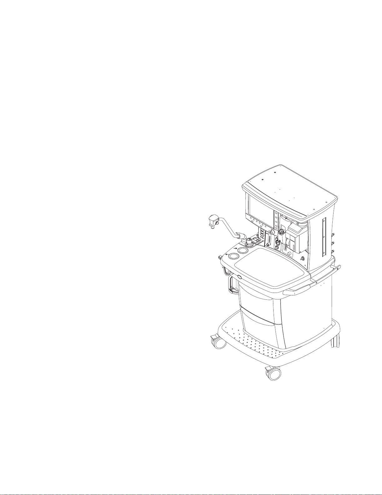
1.3 What is an S/5 Avance anesthesia machine?
The S/5 Avance anesthesia machine is a compact, integrated, and intuitive
anesthesia delivery system. It provides electronic gas mixing and optional
integrated respiratory gas monitoring.
1 Introduction
AB.91.024
Figure 1-1 • S/5 Avance system
1009-0357-000 11/03 1-3
Page 16
S/5 Avance
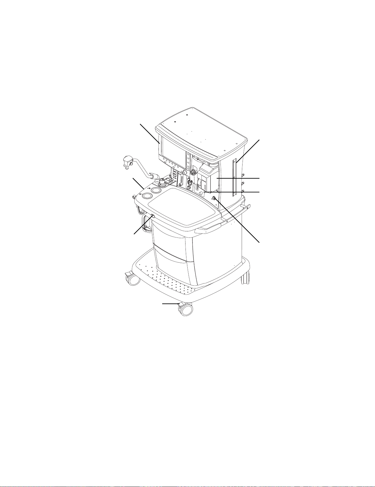
1.4 Anesthesia system components
1
2
8
7
6
3
4
5
AB.91.028
1. Anesthesia system display
2. Dovetail rails
3. Vaporizer
4. Alternate O
5. System switch
6. Brake
7. O2 flush button
8. Breathing system
2
Figure 1-2 • Front view
1-4 11/03 1009-0357-000
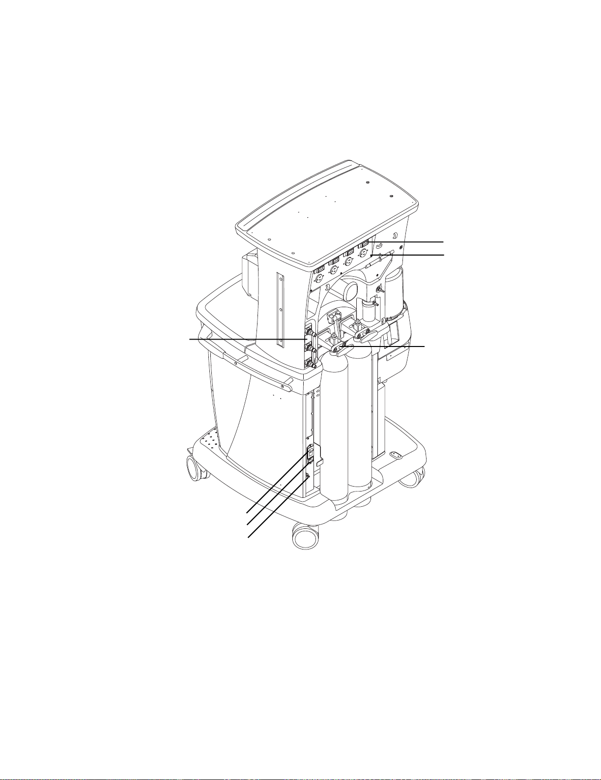
Page 17
1 Introduction
1
2
7
1. Outlet Circuit breaker (optional)
2. Electrical outlet (optional)
3. Cylinders supplies
4. Equipotential stud
5. Mains inlet
6. System circuit breaker
7. Pipeline connections
3
AB.43.085
6
5
4
Figure 1-3 • Rear view
1009-0357-000 11/03 1-5
Page 18
S/5 Avance
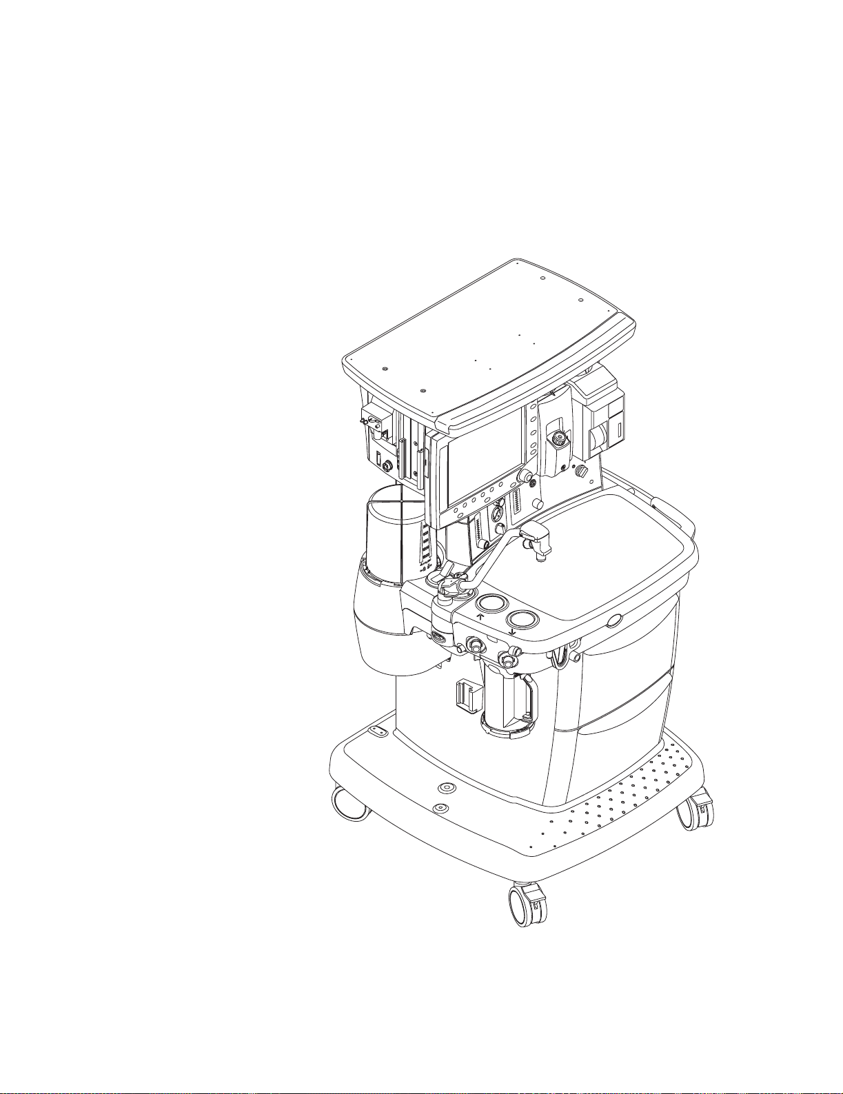
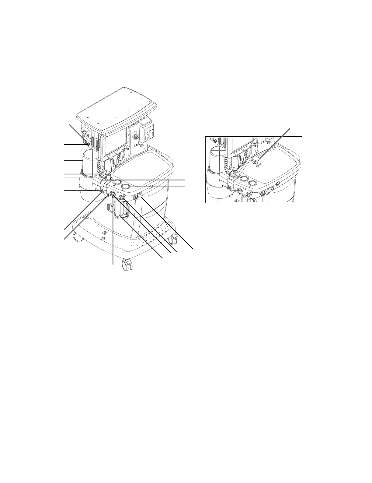
1.5 Breathing system components
15
AB.91.023
14
13
12
11
10
16
1
2
AB.91.045
9
8
6
7
1. Expiratory check valve
2. Inspiratory check valve
3. ACGO (optional)
4. Inspiratory flow sensor
5. Expiratory flow sensor
6. Absorber canister
7. Absorber canister release
8. Leak test plug
9. Breathing system release
10. Manual bag port
11. Adjustable pressure-limiting (APL) valve
12. Bag/mechanical ventilation switch
13. Bellows assembly
14. Sample gas return port
15. AGSS indicator (only available on some AGSS versions)
16. Bag support arm (optional)
3
4
5
Figure 1-4 • Breathing system
1-6 11/03 1009-0357-000
Page 19
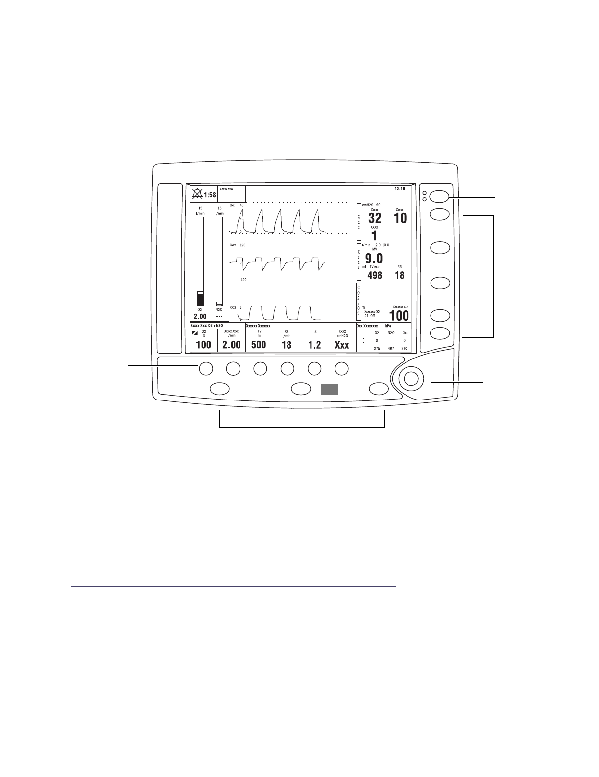
1.6 Display controls
Silence
Alarms
Alarms
Setup
1 Introduction
1
Help
4
Gas Setup
Vent Setup
Normal
Screen
2
Item Description
1 Alarm silence key Push to silence any active, silenceable high and medium
priority alarms. Alarm is silenced for 120 seconds.
Main
Menu
Checkout
Start/End
Case
2
AB.91.073
3
2 Menu keys Push to show corresponding menu.
3 ComWheel Push to select a menu item or confirm a setting. Turn right
or left to scroll menu items or change settings.
4 Quick keys Push to change corresponding gas setting or vent setting.
Use the ComWheel to make a change. Push the ComWheel
to activate the change.
Figure 1-5 • Ventilator controls
1009-0357-000 11/03 1-7
Page 20
S/5 Avance
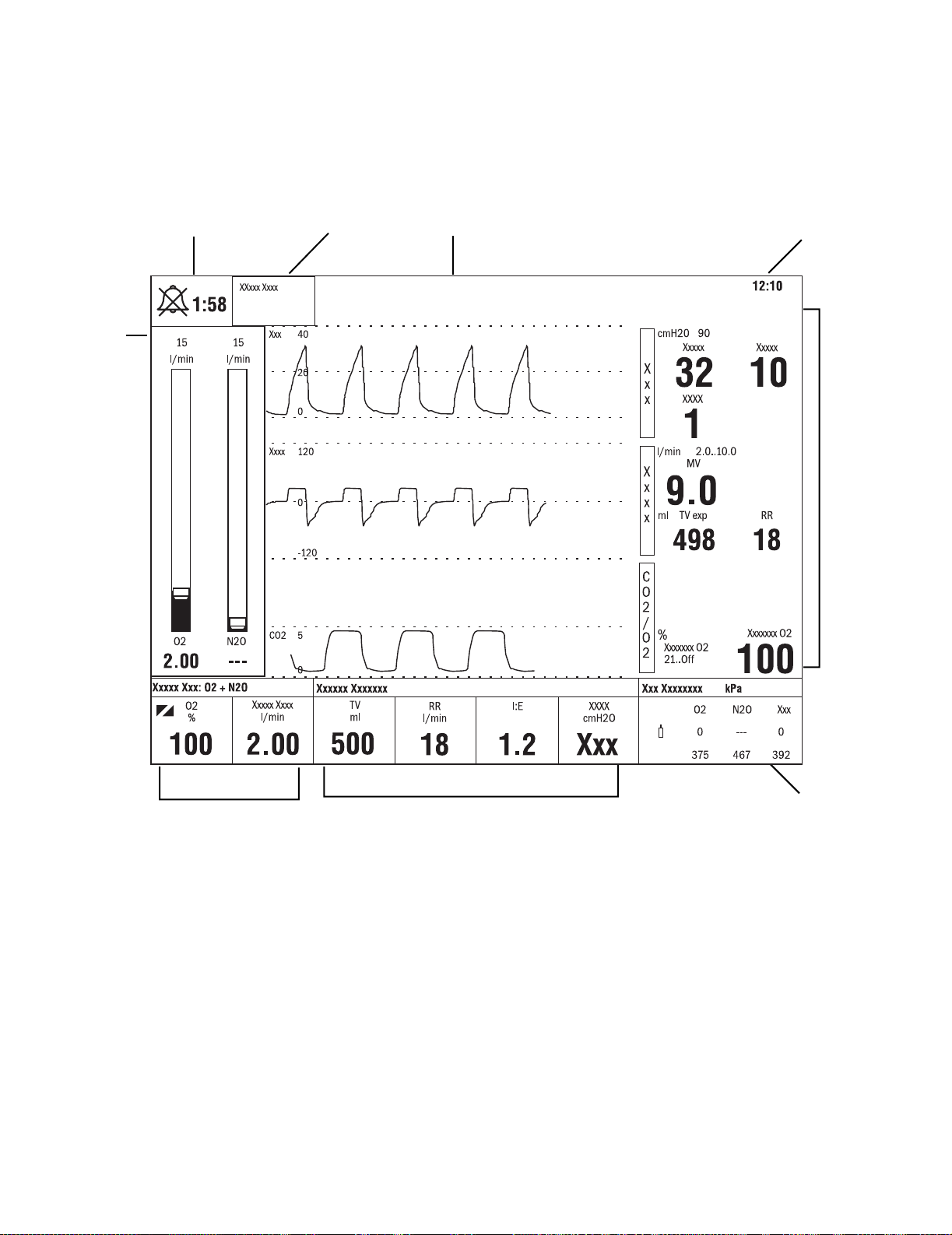
1.7 Anesthesia system display
2
1
34
5
6
AB.91.002
9
1. Electronic gas flow tubes
2. Alarm silence countdown
3. Alarm message fields
4. Waveform field
5. Clock
6. Number field
7. Free number display
8. Ventilator settings
9. Gas settings
8
7
Figure 1-6 • Normal view
1-8 11/03 1009-0357-000
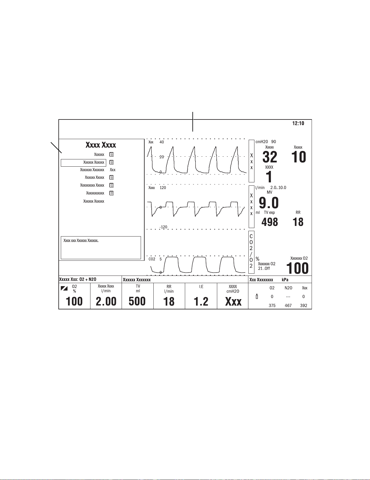
Page 21
1 Introduction
When a menu key is selected, the menu field overlays the gas flow tubes and
the waveform fields start at the right edge of the menu.
2
1
AB.91.003
1. Menu
2. Waveform fields
Figure 1-7 • Menu view
1009-0357-000 11/03 1-9
Page 22
Notes
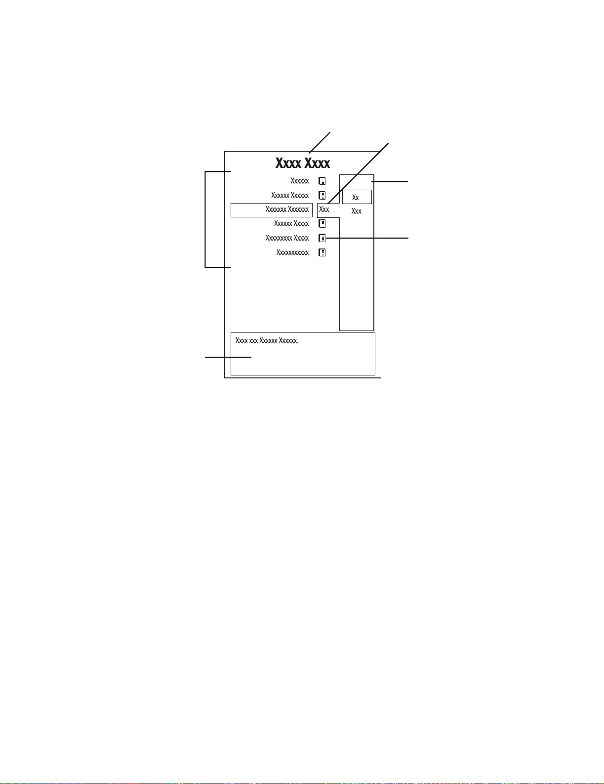
1.7.1 Using menus
Push a menu key to display the corresponding menu. Use the ComWheel to navigate
through the menu.
1
2
3
6
4
Xxxxxx Xxxxxx
5
AB.91.007
1. Menu title
2. Present selection
3. Adjustment window
4. Indicates submenu
5. Short instructions
6. Menu selections
Figure 1-8 • Example menu
1. Push the menu key to display the corresponding menu.
2. Turn the ComWheel counterclockwise to highlight the next menu item. (Turn the
ComWheel clockwise to highlight the previous menu item.)
3. Push the ComWheel to enter the adjustment window or a submenu.
4. Turn the ComWheel clockwise or counterclockwise to highlight the desired
selection.
5. Push the ComWheel to confirm the selection.
6. Select
Normal Screen
or push the
Normal Screen
return to the normal monitoring display. (Select
key to exit the menu and
Previous Menu
to return to the last
displayed menu, if available.)
1-10 11/03 1009-0357-000
Page 23

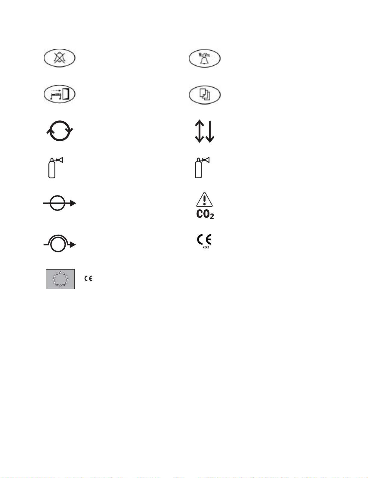
1.8 Symbols used in the manual or on the equipment
1 Introduction
m
L
l
n
Warnings and
w
you do not follow all instructions in this manual.
Warnings tell about a condition that can cause injury to the operator or the patient.
Cautions tell about a condition that can cause damage to the equipment. Read and
follow all warnings and cautions.
Other symbols replace words on the equipment or in Datex-Ohmeda manuals. No one
device or manual uses all of the symbols. These symbols include:
On (power)
Off (power)
Standby
Standby or preparatory state for part of
the equipment
w
Cautions tell you about dangerous conditions that can occur if
Alarm silence button
A
Alarm silence touch key (Tec 6).
j
J
Type B equipment
Type BF equipment
M
N
†
p
x
y
P
Y
“ON” only for part of the equipment
“OFF” only for part of the equipment
Direct current
Alternating current
Protective earth ground
Earth ground
Frame or chassis ground
Equipotential
D
w
wW
O
Type CF equipment
Caution, ISO 7000-0434
Attention, refer to product instructions,
IEC 60601-1
Dangerous voltage
Electrical input
Electrical output
Pneumatic input
Pneumatic output
1009-0357-000 11/03 1-11
Page 24

S/5 Avance
+
-
t
T
g
o
z
Plus, positive polarity
Minus, negative polarity
Variability
Variability in steps
This way up
Lamp, lighting, illumination
Lock
k
E
Movement in one direction
Movement in two directions
Read top of float
Vacuum inlet
Suction bottle outlet
Cylinder
Isolation transformer
Z
U
u
134°C
Í
q
t
Unlock
Close drain
Open drain (remove liquid)
Autoclavable
Not autoclavable
Inspiratory flow
O2 sensor connection
r
O2+
Linkage system
Risk of Explosion.
Low pressure leak test
Mechanical ventilation
Bag position/ manual ventilation
R
Expiratory flow
Q
O2 Flush button
REF
1-12 11/03 1009-0357-000
Stock Number
SN
Serial Number
Page 25
1 Introduction
< 414 kPa
Alarm silence touch key Volume alarms On/Off touch key
End case touch key Menu touch key
Circle breathing circuit module Bain/Mapleson D breathing circuit
module
< 345 kPa
The primary regulator is set to pressure
less than 345 kPa (50 psi)
Absorber on
Absorber off (CO
Bypass active)
2
European Union Representative
The primary regulator is set to pressure
less than 414 kPa (60 psi)
Bypass Option
CO
2
Systems with this mark agree with the
European Council Directive (93/42/EEC)
for Medical Devices when they are used
as specified in their User’s Reference
manuals. The xxxx is the certification
number of the Notified Body used by
Datex-Ohmeda’s Quality Systems.
1009-0357-000 11/03 1-13
Page 26

Notes
1-14 11/03 1009-0357-000
Page 27

2 Theory of Operation
In this section 2.1 Electrical system . . . . . . . . . . . . . . . . . . . . . . . . . . . . . . . . . . . . . . . . . . . . . . . . . . . . . . . . . . .2-2
2.2 Power subsystem . . . . . . . . . . . . . . . . . . . . . . . . . . . . . . . . . . . . . . . . . . . . . . . . . . . . . . . . . .2-4
2.2.1 Power Controller board . . . . . . . . . . . . . . . . . . . . . . . . . . . . . . . . . . . . . . . . . . . . . . . .2-5
2.2.2 Power distribution . . . . . . . . . . . . . . . . . . . . . . . . . . . . . . . . . . . . . . . . . . . . . . . . . . . .2-6
2.3 Display Unit . . . . . . . . . . . . . . . . . . . . . . . . . . . . . . . . . . . . . . . . . . . . . . . . . . . . . . . . . . . . . . .2-8
2.4 System communications . . . . . . . . . . . . . . . . . . . . . . . . . . . . . . . . . . . . . . . . . . . . . . . . . . . .2-9
2.5 System connections . . . . . . . . . . . . . . . . . . . . . . . . . . . . . . . . . . . . . . . . . . . . . . . . . . . . . . 2-10
2.5.1 Display Unit . . . . . . . . . . . . . . . . . . . . . . . . . . . . . . . . . . . . . . . . . . . . . . . . . . . . . . . 2-10
2.5.2 Display Connector board . . . . . . . . . . . . . . . . . . . . . . . . . . . . . . . . . . . . . . . . . . . . 2-10
2.6 Power Controller and Anesthesia Control board connections . . . . . . . . . . . . . . . . . . . . . 2-11
2.7 Anesthesia Control board . . . . . . . . . . . . . . . . . . . . . . . . . . . . . . . . . . . . . . . . . . . . . . . . . . 2-12
2.8 Electronic Gas Mixer . . . . . . . . . . . . . . . . . . . . . . . . . . . . . . . . . . . . . . . . . . . . . . . . . . . . . . 2-14
2.9 Ventilator Interface board . . . . . . . . . . . . . . . . . . . . . . . . . . . . . . . . . . . . . . . . . . . . . . . . . . 2-16
2.10 Gas flow through the anesthesia machine . . . . . . . . . . . . . . . . . . . . . . . . . . . . . . . . . . . 2-18
2.10.1 Overview . . . . . . . . . . . . . . . . . . . . . . . . . . . . . . . . . . . . . . . . . . . . . . . . . . . . . . . . 2-18
2.10.2 Physical connections . . . . . . . . . . . . . . . . . . . . . . . . . . . . . . . . . . . . . . . . . . . . . . 2-22
2.10.3 Suction regulators . . . . . . . . . . . . . . . . . . . . . . . . . . . . . . . . . . . . . . . . . . . . . . . . 2-23
2.11 Flow through the breathing system . . . . . . . . . . . . . . . . . . . . . . . . . . . . . . . . . . . . . . . . . 2-24
2.11.1 Overview of flow paths . . . . . . . . . . . . . . . . . . . . . . . . . . . . . . . . . . . . . . . . . . . . . 2-24
2.11.2 Manual ventilation . . . . . . . . . . . . . . . . . . . . . . . . . . . . . . . . . . . . . . . . . . . . . . . . 2-25
2.11.3 Mechanical ventilation . . . . . . . . . . . . . . . . . . . . . . . . . . . . . . . . . . . . . . . . . . . . . 2-28
2.11.4 Fresh gas and O
2.11.5 Fresh gas and O2 flush flow (with ACGO). . . . . . . . . . . . . . . . . . . . . . . . . . . . . . . 2-33
2.12 Ventilator mechanical subsystems . . . . . . . . . . . . . . . . . . . . . . . . . . . . . . . . . . . . . . . . . 2-35
2.12.1 Drive gas filter and Gas Inlet Valve . . . . . . . . . . . . . . . . . . . . . . . . . . . . . . . . . . . 2-35
2.12.2 Pressure regulator . . . . . . . . . . . . . . . . . . . . . . . . . . . . . . . . . . . . . . . . . . . . . . . . 2-36
2.12.3 Flow control valve . . . . . . . . . . . . . . . . . . . . . . . . . . . . . . . . . . . . . . . . . . . . . . . . . 2-36
2.12.4 Drive Gas Check Valve (DGCV) . . . . . . . . . . . . . . . . . . . . . . . . . . . . . . . . . . . . . . 2-37
2.12.5 Bellows Pressure Relief Valve . . . . . . . . . . . . . . . . . . . . . . . . . . . . . . . . . . . . . . . 2-37
2.12.6 Exhalation valve . . . . . . . . . . . . . . . . . . . . . . . . . . . . . . . . . . . . . . . . . . . . . . . . . . 2-38
2.12.7 Mechanical Overpressure Valve . . . . . . . . . . . . . . . . . . . . . . . . . . . . . . . . . . . . . 2-39
2.12.8 Reservoir and bleed resistor . . . . . . . . . . . . . . . . . . . . . . . . . . . . . . . . . . . . . . . . 2-39
2.12.9 Free breathing valve . . . . . . . . . . . . . . . . . . . . . . . . . . . . . . . . . . . . . . . . . . . . . . . 2-40
2.12.10 Breathing circuit flow sensors . . . . . . . . . . . . . . . . . . . . . . . . . . . . . . . . . . . . . . 2-40
flush flow (with SCGO). . . . . . . . . . . . . . . . . . . . . . . . . . . . . . . 2-31
2
1009-0357-000 11/03 2-1
Page 28

S/5 Avance
2.1 Electrical system
The electrical system consists of two main computing units: the Display Unit
and the Anesthesia Control board. Additional subsystems interact with these
computing hosts to perform various gas delivery, ventilation, and monitoring
functions.
The Display Unit handles the main user interface functions and connections to
external devices. The Display Unit software run on the Windows CE operating
system.
Therapy functions are handled by the Anesthesia Control board. The
Anesthesia Control board is based on the Motorola Coldfire processor with a
Nucleus operating system.
Embedded controllers are used to perform specific machine functions on
subsystems like the Power Controller board and the Mixer board.
The processors communicate through serial bus channels.
The various function of the electrical system are accomplished on the
following circuit boards:
• Display Unit CPU (A)
• Display Unit System Interconnect assembly (B)
• Display Connector board (C)
• Power Controller board (D)
• Anesthesia Control board (E)
• Pan Connector board (F)
• Electronic Mixer board (G)
• Ventilator Interface board (H)
• ABS Filter board (I)
• Vent Engine Connector board (J)
•MGAS Power Supply board (K)
• Light Strip board (L)
• Inrush board (M)
2-2 11/03 1009-0357-000
Page 29
2 Theory of Operation
K
F
L
I
G
A
AB.91.024
H
J
D
B
C
D
E
AB.91.029
M
1009-0357-000 11/03 2-3
Page 30
S/5 Avance
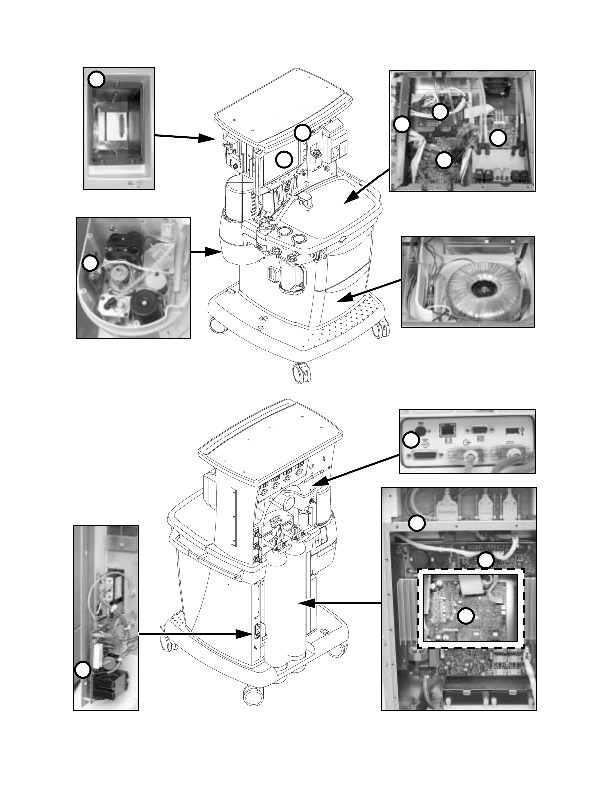
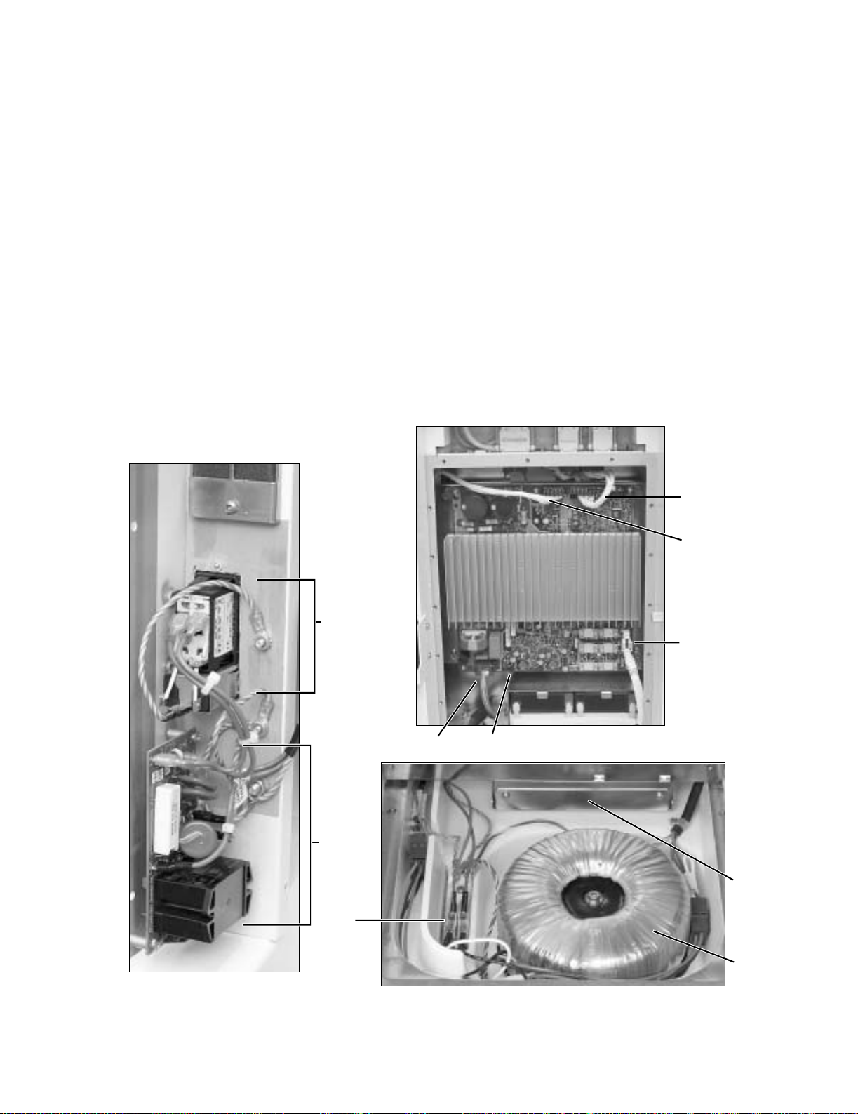
2.2 Power subsystem
Mains power enters the system through the AC Inlet module (A), which
includes a line filter and the system circuit breaker. Mains power is routed
through the Inrush (B) circuit board to the isolation transformer (C).
The isolated secondary output of the transformer is routed through fuses (D)
and a second line filter (E) to the input of the Power Controller board (F). If the
system is equipped with electrical power outlets, the transformer (larger size)
also supplies isolated power to the electrical outlets through individual circuit
breakers.
The Power Controller board interfaces with the system through:
• the Anesthesia Control board connector (G),
• the Display Connector board connector (H),
• the battery connector (I) and fan connector (J).
H
G
A
I
F
B
J
E
D
C
Figure 2-9 • Power subsystem
2-4 11/03 1009-0357-000
Page 31

2 Theory of Operation
2.2.1 Power Controller
board
The system uses a distributed power bus. The Power Controller board
contains:
• an AC/DC converter that converts line voltage to high voltage DC.
•a DC/DC converter that converts the high voltage DC to battery voltage.
•a DC/DC converter that converts battery voltage to the 12.5 VDC system bus
voltage.
The Power Controller contains supervisory circuitry that performs:
• battery charge control (battery switch circuits provide a minimum of 30
minutes of system power in the event of AC power failure).
• current, voltage, and temperature monitoring.
• AC sensing.
• fan control.
Two 12-volt batteries, wired in series, provide the back-up power.
The Power Controller communicates with the Display Unit through a RS-422,
9.6 kB channel. It receives the On/Standby signal from the system switch
through the Anesthesia Control board.
Isolation
Transformer
To
Outlets
5A Fuse
5A Fuse
Line
Filter
Figure 2-10 • Power subsystem
24V
Main s
Battery
Power
Controller
Board
AC/DC
DC/DC
Charge
Cntrl
Microcontroller
Battery
Temp
Battery
Switch
Fan 1
Battery
Anesthesia
Control Board
12.5 VDC
On/standby
Mains LED
Fan 2
Display Connector
RS-422
U
9.6Kb
A
R
T
AC
Sense
V/I
12.5 VDC
RS-422
Communications
Monitor on/standby
AB.91.061
1009-0357-000 11/03 2-5
Page 32

S/5 Avance
2.2.2 Power distribution The Power Controller board provides outputs to the Anesthesia Control board
and the Display Connector board. These boards provide local regulation of
voltages required by the system.
The Anesthesia Control board interfaces with the Mixer board and the
Ventilator Interface board through the Pan Connector board.
The Display Connector board interfaces with the Display Unit and the Module
assembly.
2-6 11/03 1009-0357-000
Page 33

2 Theory of Operation
Mains
AC
Power Controller Board
(switched bus
+22V
to
+31V
(battery
voltage)
24W
+12.5V
voltage)
+3.3V
+3.3V stdby
+12V fan1
+12V fan2
15W
Display
Connector
Board
+12.5V
(switched
bus
voltage)
10W
10W
+
1
2
.
5
V
(
s
w
i
t
c
h
e
d
b
u
s
v
o
l
t
a
g
e
)
Anesthesia Control Board
V
5
+
V
.
3
3
+
+12.5V (10VA External Expansion Port 2)
+12.5V (10VA External Expansion Port 2)
+12.5V (10VA Module Power Supply)
+12.5V (10VA Mixer)
+12.5V (10VA Mixer Gas Select Valves)
+12.5V (10VA Vent Interface Board)
+12.5V (10VA Light Power)
+12.5V (10VA Vent Valves/ACGO/SCGO)
53W
42W
Dispaly Unit CPU Board
+4.1V Step Dwn
+6.0V Step Dwn
LCD 12V
DIS 8V
Module Power Supply Board
+6V Step Dwn
+16V Boost
+/-17V Flyback
10W
CPU 3.3V
LCD 3.3V
CPU 2.5V
PCMCIA 3.3V
PCMCIA 5V
CPU 5V
FAN 5V
USB 5V
+5V LDO
+15 Vdd LDO
+15V LDO
-15V LDO
.
MGAS
Mixer Board
+3.3V
5W
4W
6W
+12.5V (10VA)
Gas Selector Valves
Ventilator Interface
Board
+5V EE
+5V Vdd
+5VA
+6V
-6V
Accessory Light
Vent Vlvs/
SCGO
Pan
Connector
Board
14.5 W
O2 RICH - 10VA
Figure 2-11 • Power distribution
1009-0357-000 11/03 2-7
AB.91.064
Page 34

S/5 Avance
2.3 Display Unit
The Display Unit handles most of the machine’s user interface functions
through the front panel controls and the LCD screen. It is the primary interface
to external peripherals.
The main components of the Display Unit include:
• An active matrix thin film transistor liquid crystal display (A)
• The CPU board (B)
• The System Interconnect assembly (C)
The CPU board includes a host processor and three coprocessors to handle
display, front panel, and monitoring interfaces.
The Display Unit includes a PCMCIA interface (D) to handle software upgrades
and to load the diagnostics Service Application.
B
A
D
C
Figure 2-12 • Display Unit
2-8 11/03 1009-0357-000
Page 35

2.4 System communications
RS-422 serial communication is used between the two main processors —
Display Unit and Anesthesia Computer — and the subsystem processors.
Various baud rates accommodate data requirements between subsystem
and host. External communication uses the standard RS-232 interface.
2 Theory of Operation
External I/O:
PCMCIA (2)
USB
RS-232 Serial
Ethernet
DIS
Microwire
DU Controls
Atmel
ATmega 16
Processor
Mgas
Intel '196Processor
ModBus
DU - UPI
Hitachi H8
processor
Bus
"I S A "
Display UnitCPU
AMD Elan SC520
Processor
l
d
a
u
i
r
a
e
b
S
K
6
.
9
C&T 69000
Display Processsor
Color LCD
RS-422
38.4 Kbaud
R
S
9
-
.
6
k
B
a
u
d
4
2
2
Ventilator
Interface
Atmel ATmega 16
Processor
Mixer Control
Atmel ATmega
103 Processor
RS-422
230 K ba u d
RS-422
Anesthesia Computer CPU
Motorola Coldfire V4
Processor
Power Supply
Controller
Atmel ATmega
103 Processor
38.4 Kbaud
1
9
.
2
K
b
a
u
d
AB.91.065
R
S
4
2
2
Future Expansion
Ports (2)
Figure 2-13 • System communications
1009-0357-000 11/03 2-9
Page 36

S/5 Avance
2.5 System connections
2.5.1 Display Unit The Display Unit accommodates the following connections:
• System Power Interface (1).
• System Signal Interface (2).
• Serial Port — standard interface for external communication (3).
• DIS connector — supports D-O Device Interface Solution (DIS) (4).
• Network connection — Standard Ethernet port for network connectivity (5).
• Network ID — accept D-O proprietary network identification plug (6).
• USB port — standard USB 1.1 interface for external communication with
items such as a printer (7).
4 5 6 7
2.5.2 Display Connector
board
3 2 1
The top side of the Display Connector board accepts the following cables:
• System Power Interface to Display Unit (1).
• System Signal Interface to Display Unit (2).
• Airway Module (MGAS) Power Supply board (8).
• Not used (9).
• The under side of the Display Connector board accepts the following cables:
• Power Controller board (10).
• Anesthesia Control board (MGAS power) connector (11).
• Anesthesia Control board (signal) connector (12).
• Not used (13).
9 8 2 1
10111213
2-10 11/03 1009-0357-000
Page 37

2 Theory of Operation
2.6 Power Controller and Anesthesia Control board connections
The Power Controller:
• Distributes 12.5 VDC power and communicates with the Display Unit (by
way of the Display Connector board) through the connector (10).
• Distributes 12.5 VDC power to the Anesthesia Control board through
connector (14).
The Anesthesia Control board:
• Receives power from the Power Controller board through connector (14).
• Distributes 10VA power supplies to the Pan Connector board through
connector (15).
• Communicates with Pan assemblies through connector (16).
• Communicates with Display Unit through connector (12).
• Distributes 10VA power supplies to the Display Unit through connector (11).
1415
Display Connector board
(topside)
14
11
16
10
12
Power Controller board
Display Connector board
Display Connector board
(underside)
(underside)
Anesthesia Control board
14
1009-0357-000 11/03 2-11
Page 38

S/5 Avance
2.7 Anesthesia Control board
The Anesthesia Control board (A) uses a Motorola MCF5307 Coldfire
microcontroller with 4M Flash and 16M error correcting DRAM. The
Anesthesia Control board includes 6 UARTs with a 64 byte FIFO and RS-422
communications to interface with the Display Unit, an accessory port, and
anesthesia delivery subsystems located in the pan electronic enclosure.
These include the Gas Mixer and the Ventilator Interface board.
A
Figure 2-14 • Anesthesia Control board
2-12 11/03 1009-0357-000
Page 39

ON/Standby and Mains LED
12.5VDC
12.5VDC
Power Controller Board
12.5VDC
+3.3V Supply
+1.8V Supply
+5V Supply
4 MB Flash
Address Bus
Data Bus
10VA Power
Monitoring
Glue Logic
SW Test LEDs
O2 Bypass
I2C
10VA Limit
Circuitry
Backup
Audio and
Sounder
Gas Select
Valve Drivers
Pipeline and
Cylinder
Pressure
Transducer
Interface
Vent
Mixer
Accessory
MGAS
Accessory 1
Accessory 2
O2 Select
Air Select
N2O Select
O2 Bypass
O2 Pipe Presr
Air Pipe Presr
N2O Pipe Presr
O2 Cyl Presr
AIR Cyl Presr
N2O Cyl Presr
2nd O2 Cyl Presr
2 Theory of Operation
AB.91.062
Pan Connector
Board Power
Board Power (10VA)
Display Connector
Pan Connector Board Signal
16 MB
SDRAM
Memory
Error
Detection
and
Correction
Figure 2-15 • Anesthesia Control board block diagram
MCF 5407
Motorola V4
Coldfire
Microcontroller
EEPROM
Mixer Com
UARTs
Vent Com
6 Channels
64-byte FIFO
6-RS-422
BDMClock
Acsry 1 Com
DU com
Acsry 2 Com
Display Connector
Board Signal
Debug Mode
Background
1009-0357-000 11/03 2-13
Page 40

S/5 Avance
2.8 Electronic Gas Mixer
The Gas Mixer receives its pneumatic inputs from the pipeline and cylinder
supplies and sends mixed gas to the vaporizer manifold. The Gas Mixer
interfaces to the Anesthesia Control board for power and communications.
The Gas Mixer consists of the following subassemblies and main components:
• Gas Mixer board (A)
• Control Manifold (B) — manifold, selector valves, proportional valves
• Flow sensor assembly (C)
•Mixed gas manifold and exit check valve (D)
A
D
C
B
Figure 2-16 • Electronic Gas Mixer
2-14 11/03 1009-0357-000
Page 41

2 Theory of Operation
Desired gas flows are sent from the Anesthesia Control board to the Gas
Mixer.
Gas Mixer operation is controlled through a microcontroller which:
• Opens and closes selector valves for O
• Regulates flow control valves for O
, N2O and Air.
2
and balance gas (N2O or Air).
2
Closed-loop flow control is accomplished through a hot-wire anemometer in
concert with the flow control valves. Gas flow, based on a calibration table, is
on target when the reference measurement equals the flow measurement.
Pressure measurements across each of the flow sensor channels are used as
checks on the flow measurement for hazard mitigation, ambient pressure
compensation, and compensation for back pressure downstream of the
Mixer.
A
C
B
RS-422 Serial
Interface Driver
O
A
R
12.5 VDC
D
3.3 VDC
Regulator
Balance Gas
Valve Drive
Oxygen Valve
Drive
Selector and Bypass Valves
130 ma max.
VDD
5.5 VDC
Regulator fro
Flow Sensors
350 ma max.
Atmel AVR Mega103L
Processor with 124K
Flash, 2K RAM
SPI Port
12 Bit A/D
Self Test Analog
Mutiplexer
Watchdog
Analog
References
CODE
CPU
RCV
XMIT
VLV1
VLV2
FAIL
Diagnostic
Indicators
AB.91.063
FAN Hi/Lo
Regulator
Press.
Signal
Conditioning
Oxygen
T1 F1
Press.
Vaporizer
Balance
Press.
Gas
Temperature, Flow, and
Pressure Sensors
T2 F2
Figure 2-17 • Electronic Gas Mixer block diagram
1009-0357-000 11/03 2-15
Page 42

S/5 Avance
2.9 Ventilator Interface board
The Ventilator Interface board (A) provides the electrical and/or pneumatic
interface to the following:
• Inspiratory (B) and expiratory (C) flow sensors (transducers)
• Patient airway (D) and manifold (E) pressures (transducers)
• Oxygen sensor (in breathing system)
• ABS On switch
• ACGO position switch (if ACGO installed)
• SCGO solenoid, SCGO/CGO position switches (if SCGO installed)
• Bag/Vent switch
•O
Flush switch
2
• Gas Inlet Valve
• Inspiratory Flow Valve
• Accessory Power (for task lights)
The Ventilator Interface board functions are managed locally by a
microcontroller. The microcontroller communicates data values to the
controlling CPU via an RS-422 serial interface.
E
C
A
Figure 2-18 • Ventilator Interface board
2-16 11/03 1009-0357-000
D
B
Page 43

Exp Data
Insp Data
E2 Clk
E2 +5.0V
E2 GND
Bag/Vent Sw
O2 Flush Sw
O2 Disconnect
ACGO/SCGO Sw
CGO Sw
ABS On Sw
SCGO
I2C MUX
to Flow Sensors
+5V
Reg.
E
2
P
w
r
O
n
Parallel I/O
SCGO
SCGO On
Driver
I
C
M
U
X
S
e
l
+12.5V Accessory Power
+12.5V Valve Power
+12.5V
I
2
2
C
P
o
r
t
+5.0VA
+5.0VDD
+6.0VA
-6.0VA
Emulator
Header
ATMEGA16
Microcontroller
ADC
10-Bit
Filter
Local Power
Supply
Regulators
Activity Indicators
Reset, Watchdog,
Txd & Rxd
RxD
TxD
Transceiver
Reset
W_Dog
Watchdog and
Under-Voltage
RS-422
Monitor
2 Theory of Operation
AB.91.062
P
a
n
C
o
n
+12.5V
n
e
c
t
o
r
B
o
a
r
d
GIV Drv
GIV
Driver
ABSFilter Board
Flow
Valve
Driver
B
F
e
v
i
r
D
w
o
l
F
3.2 VREF
O2 Sensor
Ventilator Interface Board
Over_Press
8-Channel
Flow DAC FB
O2 Signal
Amp/Filter
GIV On
ISP
Header
Local Power
Supply Monitors
S
P
I
P
o
r
t
SPI AD DR0
SPI AD DR1
DAC LD
SPI Addr
Decoder
DAC
12-Bit
ADC
12-Bit
Amp/Filter Amp/Filter Amp/Filter Amp/Filter
Inspiratory
Transducer
FL DAC CS
FL DAC LD
Expiratory
Transducer
ADC CS
Manifold
Transducer
VDD Over-
Voltage Monitor
+12.5V
SPI C S
Ove r_Pre s s
Comp
VREF
Over_Press
Airway_Press
A
n
a
l
o
g
T
e
s
t
C
o
n
n
e
c
t
o
r
Manifold_Press
Inspiratory_Press
Expiratory_Press
AB.91.080
Airway
Transducer
Figure 2-19 • Ventilator Interface board block diagram
1009-0357-000 11/03 2-17
Page 44

S/5 Avance
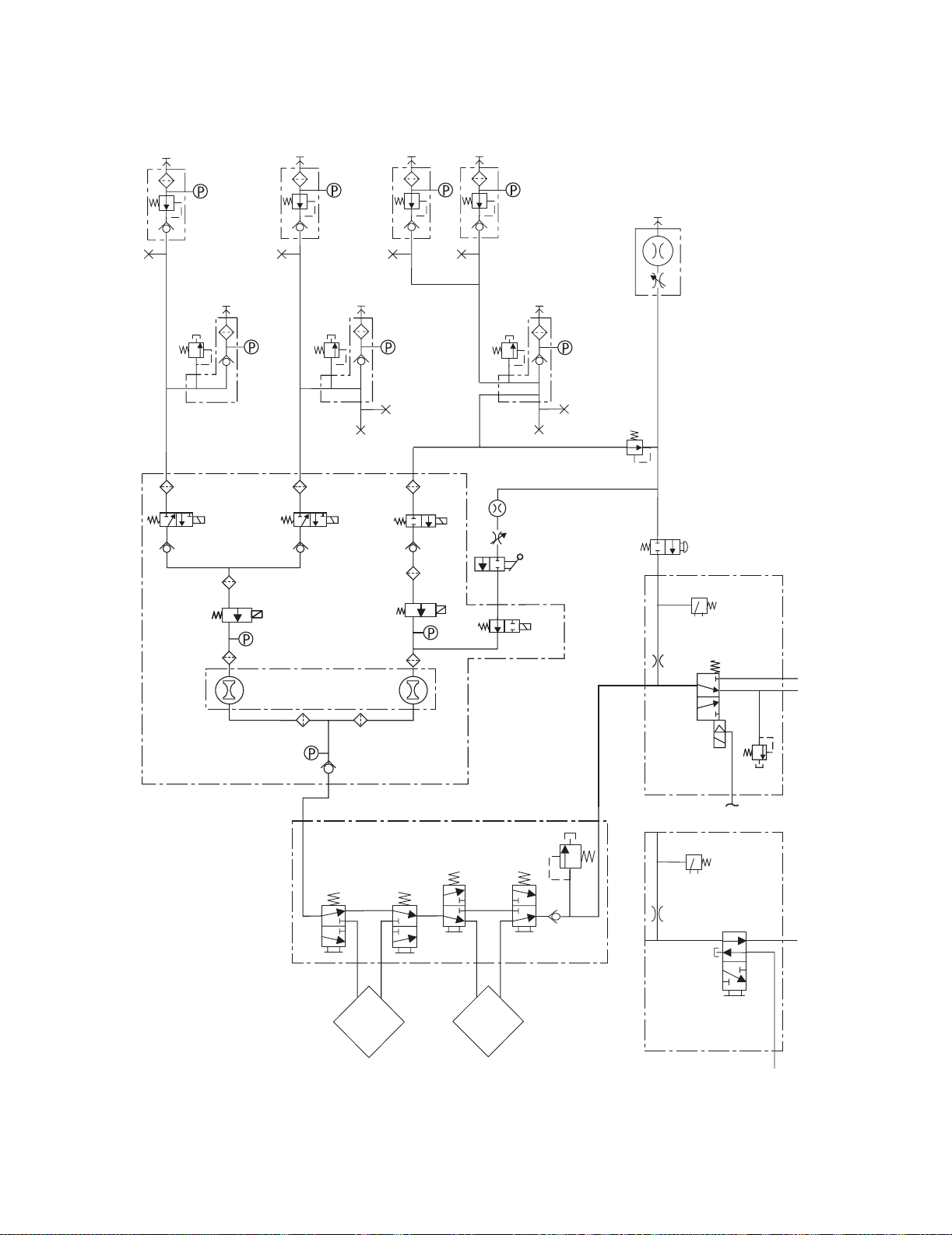
2.10 Gas flow through the anesthesia machine
2.10.1 Overview Refer to Figure 2-20.
Gas supplies Gas comes into the system through a pipeline (1) or cylinder (6) connection.
All connections have indexed fittings, filters, and check valves (one-way
valves). Pressure transducers monitor the pipeline (2) and cylinder (7)
pressures.
The O
supply failure alarm is derived from the O2 pipeline and the O2 cylinder
2
pressure transducer inputs.
A primary regulator (8) decreases the cylinder pressures to approximately
pipeline levels. A pressure relief valve (3) helps protect the system from high
pressures.
To help prevent problems with the gas supplies:
• Install yoke plugs on all empty cylinder connections.
•When a pipeline supply is adequate, keep the cylinder valve closed.
Gas flow Pipeline or regulated cylinder pressure supplies O
or Air directly to the
2
ventilator engine (4a or 4b) and as pilot pressure (4) for the SCGO
assembly (E). Connection points are also available for venturi
suction (5a or 5b) drive gas supply. An additional O
the pressure for the O
Flush valve supplies high flows of O2 to the fresh gas outlet (22 or 23)
The O
2
Flush valve (19) and the auxiliary O2 flowmeter (24).
2
regulator (18) decreases
2
through the SCGO/ACGO assembly (E/F). The flush pressure switch (20)
monitors activation of the flush valve.
Gas mixing Under normal conditions, with the system switch (10) in the On position, the
Alternate O
Normal gas flows are enabled through their respective selector valves (11).
The system controls gas flow through the flow control valves (12) and derives
the individual flow rates through the hot-wire anemometers (14).
Under system failure conditions (or if Alt O
Alternate O
Flowmeter when the system switch is in the On position.
Disable valve (13) is energized to block alternate O2 flow.
2
is selected), the normally-open
2
Disable valve (13) allows delivery of O2 through the Alternate O2
2
Mixed gas The mixed gas flows through the vaporizer manifold (D), and vaporizer (16)
that is On, to the SCGO/ACGO assembly (E/F). A pressure relief valve (17 ) on
the vaporizer manifold sets the maximum outlet pressure.
The SCGO assembly (E) directs the mixed gas to the selected circuit:
22 (ABS-circle) or 23 (to Inspiratory port of ABS). On SCGO assemblies, a
relief valve (21) limits pressure in the breathing system to approximately
150 cmH
O.
2
The ACGO assembly (F) directs the mixed gas to the selected circuit:
22 (ABS-circle) or 23 (external ACGO port).
2-18 11/03 1009-0357-000
Page 45

N2O
Air O
2
O
2
6666
2 Theory of Operation
77
8
B
8
B
B
7
8
B
7
8
9999
1
3
A
2
1
3
A
2
1
3
5b
4b
4a
C
11c 11b 11a
10
12b
12a
13
24
A
2
5a
18
19
20
E
14b
A - Pipeline Manifold
B - Cylinder Supply
C - Gas Mixer
D - Vaporizer Manifold
E - SCGO Assembly
F - ACGO Assembly
P - Pressure Transducer
Figure 2-20 • Pneumatic circuit
15 15
16
14a
15 15
16
17
22
23
21
4
D
20
F
22
AB.91.070
23
1009-0357-000 11/03 2-19
Page 46
S/5 Avance
N2O
6666
Air O
2
O
2
77
8
B
8
B
B
7
8
B
7
8
9999
1
3
A
2
1
3
A
2
1
3
5b
4b
4a
C
11c 11b 11a
10
12b
12a
13
24
A
2
5a
18
19
20
E
14b
A - Pipeline Manifold
B - Cylinder Supply
C - Gas Mixer
D - Vaporizer Manifold
E - SCGO Assembly
F - ACGO Assembly
P - Pressure Transducer
Figure 2-21 • Pneumatic circuit
15 15
16
14a
15 15
16
17
22
23
21
4
D
20
F
22
AB.91.070
23
2-20 11/03 1009-0357-000
Page 47

Refer to Figure 2-21.
2 Theory of Operation
Key to Numbered
Components
1. Pipeline inlet
2. Pipeline pressure transducer
3. High-pressure relief valve (758 kPa / 110 psi)*
4. Supply connections for the ventilator and pilot pressure for SCGO
drive gas
a. O
2
b. Air drive gas
5. Venturi suction supply connection
a. O
drive gas
2
b. Air drive gas
6. Cylinder inlet
7. Cylinder pressure transducer
8. Primary regulator (cylinder pressure)
9. Test port (primary regulator)
10. System switch
11. Selector valve
a = O
; b = Air; c = N2O
2
12. Flow controller
; b = balance gas
a = O
2
13. Alternate O
disable valve
2
14. Hot-wire anemometer
a = O
flow sensor channel; b = balance gas flow sensor channel
2
15. Vaporizer port valve
16. Vaporizer
17. Low-pressure relief valve (38 kPa / 5.5 psi)*
18. O
flush and auxiliary flowmeter regulator (241 kPa / 35 psi)*
2
19. O
Flush valve
2
20. Pressure switch (used with the ventilator)
21. Breathing system pressure relief valve (SCGO only — 150 cmH
2
22. To Port 3 of ABS interface (circle)
23. For SCGO, to Port 2 of ABS interface (non-circle Inspiratory port)
For ACGO, to external 22-mm ACGO connector
24. Auxiliary O
flowmeter (optional)
2
* Approximate values
O)*
Key to Symbols
Pneumatic Connection
Filter
Direction of Flow
Check Valve
1009-0357-000 11/03 2-21
Page 48

S/5 Avance
2.10.2 Physical
connections
15 15
17
Figure 2-22 shows the physical path that the gas takes. The item numbers are
described on the previous page.
19
19
P
14a14b
ACGO
22
SCGO
23
22
4
Pilot
ABS
Port 3
ABS
Port 2
Port 3
P
13
Mixer
11b
P
12a12b
11c
11a
24
2
P
10
N2O
O
Air
3
2
P
2
3
2
P
3
4b
4a
77
9
To
P P
8 8
Pilot
6 6
SCM
Vacuum
9
Suction
1
1
1
To Vent Drive
AB.91.059
Figure 2-22 • Typical tubing connections - pictorial
2-22 11/03 1009-0357-000
Page 49

2 Theory of Operation
2.10.3 Suction
regulators
Pipeline vacuum
The suction regulator (shown in Figure 2-22) uses an external vacuum source.
Venturi Drive vacuum
The suction regulator (shown in Figure 2-23) uses an internal, venturi derived vacuum
source.
Drive gas (internally plumbed Air or O
(A). As the drive gas passes through the venturi module, a vacuum is created at port B.
The drive gas exits the venturi module at port C and is exhausted outside the machine
through the muffler (D).
The control port (E) on the venturi module responds to pneumatic signals from the front
panel switch on the Suction Control Module (SCM) to turn the venturi vacuum drive gas
on or off. The check valve (CV) helps prevent pressurization of the suction circuitry if the
exhaust is occluded or the venturi unit fails.
) enters the Venturi Module (VM) at the drive port
2
Venturi Drive Gas
Air or O
E
A
2
B
CV
VM
C
SCM
Suction
AB.74.049
D
Figure 2-23 • Venturi suction
1009-0357-000 11/03 2-23
Page 50

S/5 Avance
2.11 Flow through the breathing system
2.11.1 Overview of
flow paths
This section looks at three types of flow paths.
• Ventilation paths: How gas flows from the drive source (bag or bellows) to and from
the patient.
• Fresh gas paths: Fresh gas can flow from the machine interface directly to the patient
through the inspiratory check valve, or through the absorber into the expiratory flow,
or directly to an external circuit through the optional auxiliary common gas outlet.
• Scavenged gas paths: APL or Pop-off.
2-24 11/03 1009-0357-000
Page 51

2.11.2 Manual ventilation
2 Theory of Operation
Manual inspiration
(Figure 2-24)
The Bag/Vent switch closes the ventilator path (B)..
Gas flows from the bag (1), through the absorber (2), into the breathing circuit module,
and through a unidirectional valve (inspiratory check valve) to the patient (3).
During inspiration, fresh gas (FG) flows from the machine into the inspiratory limb,
upstream of the inspiratory check valve.
..
AP
FG
B
3
2
1
3
AP Airway Pressure
B Bag/Vent switch to Bag
FG Fresh Gas
1 Flow to absorber
2 Flow from absorber
3 Inspiratory flow
Figure 2-24 • Gas flow during manual inspiration
AB.82.026
1
1009-0357-000 11/03 2-25
Page 52

S/5 Avance
Manual expiration
(Figure 2-25)
The Bag/Vent switch keeps the ventilator path closed (B).
Gas flows from the patient (4), through a unidirectional valve (expiratory check valve),
and into the bag (5).
During exhalation, fresh gas flows backwards through the absorber (FG) into the
expiratory limb, downstream of the expiratory check valve.
For machines that are plumbed to return sample gas to the breathing system, the
returned gas (SGR) enters the breathing system after the expiratory check valve
(Refer to section 9.23).
AP
FG
SGR
B
AP Airway Pressure
B Bag/Vent switch to Bag
FG Fresh Gas
SGR Sample Gas Return
4 Expiratory flow
5 Flow to bag
5
4
4
AB.82.027
FG
Figure 2-25 • Flow during manual expiration
2-26 11/03 1009-0357-000
Page 53

2 Theory of Operation
APL Valve
(Figure 2-26)
7
The APL valve sets a pressure limit for manual ventilation.
As you turn the APL knob, it puts more or less force on the APL disc and seat (D/S). If
the circuit pressure is too high (6), the disc and seat inside the diaphragm opens and
vents gas to the scavenging system (7).
D/S
6
D/S APL disc and seat
6 APL flow
7 To scavenging
7
AB.82.028
Figure 2-26 • Flow through the APL Valve
1009-0357-000 11/03 2-27
Page 54

S/5 Avance
2.11.3 Mechanical ventilation
Mechanical inspiration
(Figure 2-27)
The Bag/Vent switch closes the manual path (V). Pilot pressure (P) closes the
exhalation valve.
Drive gas (D) pushes down on the bellows. Gas flows from the bellows (1), through the
absorber (2), and through a unidirectional valve (inspiratory check valve) to the patient
(3).
During inspiration, fresh gas flows into the inspiratory limb, upstream of the inspiratory
check valve.
AP
D
FG
1
3
D
P
AP Airway Pressure
D Drive gas
FG Fresh Gas
P Pilot pressure
V Bag/Vent switch to Vent
1 Flow to absorber
2 Flow from absorber
3 Inspiratory flow
V
3
2
AB.82.029
Figure 2-27 • Mechanical inspiration
2-28 11/03 1009-0357-000
Page 55

2 Theory of Operation
Mechanical expiration
(Figure 2-28)
Drive-gas flow stops and the exhalation valve opens. Exhaled gas flows from the
patient (4), through a unidirectional valve (expiratory check valve) and into the bellows
(5). Residual drive gas (D) flows out of the bellows to the scavenging system (6).
If PEEP is selected, static pressure on the pilot port of the exhalation valve sets the
PEEP level.
During exhalation, fresh gas flows backwards through the absorber (FG) into the
expiratory limb, downstream of the expiratory check valve.
For machines that are plumbed to return sample gas to the breathing system, the
returned gas (SGR) enters the breathing system after the expiratory check valve
(Refer to section 9.23).
AP
FG
SGR
D
6
AP Airway Pressure
D Drive gas
FG Fresh Gas
SGR Sample Gas Return
4 Expiratory flow
5
5
4
AB.82.030
FG
5 Flow to bellows
6 To scavenging
Figure 2-28 • Flow through the APL Valve
1009-0357-000 11/03 2-29
Page 56

S/5 Avance
Pop-off valve
(Figure 2-29)
7
The pop-off valve limits the pressure inside the bellows to 2.5 cm H2O above the drive
gas pressure. This normally occurs when the bellows reaches the top of the housing at
the end of exhalation.
Excess gas (7) vents to the scavenging system (6) through the pop-off valve and the
exhalation valve.
6
6 Pop-off flow
7 To scavenging
AB.82.031
Figure 2-29 • Flow through the pop-off valve
2-30 11/03 1009-0357-000
Page 57

2.11.4 Fresh gas and O2 flush flow (with SCGO)
2 Theory of Operation
To ABS (Circle)
breathing system
(Figure 2-30)
Fresh gas (1) flows from the vaporizer manifold outlet to the SCGO assembly.
With the Circle system selected, fresh gas flow is channeled to Port 3 of the breathing
system (before the inspiratory check valve).
The output of the O
When activate, O
Flush regulator (2) is channeled to the O
2
flush flow joins the fresh gas flow in the SCGO assembly.
2
Flush valve.
2
1
ABS
SCGO
Assembly
2
AB.91.071
Figure 2-30 • Fresh gas anP29d O2 flush flow (to ABS)
1009-0357-000 11/03 2-31
Page 58

S/5 Avance
Switched (Non-circle)
Common Gas Outlet
(Figure 2-31)
Fresh gas (1) flows from the vaporizer manifold outlet to the SCGO assembly.
With the Non-Circle system selected, fresh gas flow is channeled to Port 2 of the
breathing system (after the inspiratory check valve - to an external patient circuit
through the Inspiratory port).
The output of the O
When activated, O
Flush regulator (2) is channeled to the O
2
flush flow joins the fresh gas flow in the SCGO assembly.
2
Flush valve.
2
1
2
ABS
Figure 2-31 • Fresh gas and O2 flush flow (to ACGO)
2-32 11/03 1009-0357-000
SCGO
Assembly
AB.91.072
Page 59

2.11.5 Fresh gas and O2 flush flow (with ACGO)
2 Theory of Operation
To ABS (Circle)
breathing system
(Figure 2-32)
Fresh gas (1) flows from the vaporizer manifold outlet to the ACGO Selector Switch.
With the ACGO Selector Switch in the ABS position, fresh gas flow is channeled to the
breathing system.
The output of the O
When activate, O
Flush regulator (2) is channeled to the O
2
flush flow joins the fresh gas flow in the ACGO Selector Switch.
2
Flush valve.
2
1
2
ABS
ACGO
Selector
Switch
AB.74.060
Figure 2-32 • Fresh gas and O2 flush flow (to ABS)
1009-0357-000 11/03 2-33
Page 60

S/5 Avance
Auxiliary (Non-circle)
Common Gas Outlet
(Figure 2-33)
Fresh gas (1) flows from the vaporizer manifold outlet to the ACGO Selector Switch.
With the ACGO Selector Switch in the ACGO position, fresh gas flow is channeled to the
ACGO outlet.
At the ACGO outlet, a small sample is diverted to the O
Cell in the ABS for O2
2
monitoring.
The output of the O
When activated, O
Flush regulator (2) is channeled to the O
2
flush flow joins the fresh gas flow in the ACGO Selector Switch.
2
Flush valve.
2
1
Cell
O
2
O2 Sense
ACGO
2
AB.74.061
ACGO
Selector
Switch
Figure 2-33 • Fresh gas and O2 flush flow (to ACGO)
2-34 11/03 1009-0357-000
Page 61

2.12 Ventilator mechanical subsystems
0
e Gas C ec a e
t
Refer to Figure 11-1, "System circuit diagram" in Section11, for the complete
pneumatic/mechanical subsystem diagram.
The mechanical subsystems for the ventilator include:
Pneumatic Vent Engine
• Drive gas inlet filter
• Gas inlet valve
• Supply gas pressure regulator
• Flow control valve
• Drive gas check valve
• Mechanical Overpressure Valve (MOPV)
• Bleed resistor
• Free breathing valve
Exhalation valve
Bellows assembly
2 Theory of Operation
2.12.1 Drive gas
filter and Gas Inlet
Valve
Breathing circuit flow sensors
Drive gas (can be selected from O2 or Air) enters the Vent Engine (1) at a pressure of
241 to 690 kPa (35 to 100 psi) through a 2-micron filter (2) that is located under the
Gas Inlet Valve (3).
During normal operation the Gas Inlet Valve (GIV) is open to let supply gas flow. The GIV
provides a shutoff of the supply gas when the ventilator is not in use. The GIV also shuts
off supply gas to the ventilator under failure conditions detected by the CPU or overpressure switch. The output from the GIV stays at the filtered supply gas pressure.
25 psig @
15 LPM
(2.
Vent to Ambient
(3.5 cm H2O bias)
Inspiratory Flow
Control Valve
Alternate O2
1
3
2
Disable Valve
P
low
roller
Gas Inlet
Valve
P
Figure 2-34 • Inlet filter and Gas Inlet Valve (GIV)
1009-0357-000 11/03 2-35
Page 62

S/5 Avance
(2.0 cm
2
(3.5
H2O bias)
l
e
C
t
m
2
C
f
2.12.2 Pressure
regulator
The pressure regulator (4) is a non-relieving pressure regulator that regulates high
pressure filtered supply gas down to 172 kPa (25 psi).
4
Figure 2-35 • Pressure regulator
rnate O2
able Valve
P
er
cm
Inspiratory Flow
Control Valve
P
Gas Inlet
Valve
25 psig @
15 LPM
Vent to Ambient
2.12.3 Flow
control valve
The flow control valve (5) is controlled by the CPU. Signals are sent to the flow control
valve of the necessary flow determined by ventilator settings and sensor signals. The
flow control valve modulates the incoming 172 kPa (25 psi) drive gases to an output
from 0 to 120 liters per minute at pressures ranging from 0 to 100 cm H
5
Figure 2-36 • Flow control valve
rnate O2
ble Valve
Vent Engine
Free Breathing
Check Valve
Mechanical Over Pressure
Valve (110 cm H2O)
Drive Gas Check Valve
(3.5 cm H2O bias)
Inspiratory Flow
Control Valve
Atmosphere
Gas Inlet
Valve
2
O.
25 psig @
15 LPM
Popoff
Valve
Exhala
(2.0 c
i
2-36 11/03 1009-0357-000
Page 63

2 Theory of Operation
a
o
b
m
e
a
o
b
m
e
2.12.4 Drive Gas
Check Valve
(DGCV)
The Drive Gas Check Valve (6) is used downstream of the flow control valve to create
the pilot pressure for closing the exhalation valve during inspiratory phases, The DGCV
valve is biased shut by an integral weight that supplies approximately 3.5 cm H
O of
2
bias pressure before permitting flow downstream to the breathing circuit. When the
ventilator is exhausting flow from the breathing circuit, the DGCV permits the exhalation
valve pilot pressure to be de-coupled from the circuit pressure. This permits the
exhalation valve to open and lets gas flow to the exhaust and the gas scavenging
system.
6
Vent Engine
Free Breathing
Check Valve
Mechanical Over Pressure
Valve (110 cm H2O)
Drive Gas Check Valve
(3.5 cm H2O bias)
Inspiratory Flow
Control Valve
Atmosphere
Gas Inlet
Valve
Popoff
Valve
25 psig @
15 LPM
Exhalation Valve
(2.0 cm H2O bias)
200 mL Reservoir
Control Bleed to Am
1.0 LPM @ 3.0 c
if continuous (rate d
0-10 LPM D
0-10 LPM P
0-20 LPM T
2.12.5 Bellows
Pressure Relief
Valve
Figure 2-37 • Drive Gas Check Valve
The Bellows assembly is the interface between drive gas and patient gas in the
breathing system. The pressure relief valve (or pop-off valve) in the bellows
assembly (7) controls the pressure in the breathing circuit and exhausts excess patient
gas through the exhalation valve.
The pressure relief valve is normally closed, maintaining approximately 1.5 cm H
O in
2
the breathing circuit in a no-flow condition, enough to keep the bellows inflated. It is
piloted closed during inspiration and remains closed until the bellows is refilled during
exhalation. It will exhaust ≤ 4 L/min excess fresh gas flow at ≤ 4 cm H
Vent Engine
Mechanical Over Pressure
Valve (110 cm H2O)
7
Free Breathing
Check Valve
Drive Gas Check Valve
(3.5 cm H2O bias)
Inspiratory Flow
Control Valve
Atmosphere
Gas Inlet
Valve
Popoff
Valve
25 psig @
15 LPM
2
O.
Exhalation Valve
(2.0 cm H2O bias)
200 mL Reservoir
Control Bleed to Am
1.0 LPM @ 3.0 c
if continuous (rate d
0-10 LPM D
0-10 LPM P
0-20 LPM T
Figure 2-38 • Bellows pressure relief valve
1009-0357-000 11/03 2-37
Page 64

S/5 Avance
B
w
v
e
c
n
2.12.6 Exhalation
valve
The exhalation valve contains an elastomeric diaphragm that is used along with the
flow valve to control the pressures in the breathing circuit. The exhalation valve
includes two male ports on the bottom for:
• Bellows drive gas (8)
• Exhalation valve pilot (9) - (manifold pressure)
The exhalation valve includes three ports on top that connect to the bellows base
manifold:
• Drive gas pass through (10)
• Drive gas return and pop-off valve flow (11)
• APL exhaust flow to scavenging (12)
A port at the back of the exhalation valve (13) connects to the down tube that directs all
the exhaust flows to the scavenging receiver.
The exhalation valve is normally open. Approximately 2 cm H
O of pilot pressure is
2
necessary to close the valve. When the exhalation port is open, gas flows from the
bellows housing to the scavenging port.
13
Atmosphere
11
10
8
12
9
e Breathing
ck Valve
l Over Pressure
m H2O)
Drive Gas Check Valve
(3.5 cm H2O bias)
spiratory Flow
Control Valve
Gas Inlet
Valve
Popoff
Valve
25 psig @
15 LPM
Exhalation Valve
(2.0 cm H2O bias)
0-10 LPM Drive Gas
0-10 LPM Patient and Fres
0-20 LPM Total Typical Flo
200 mL Reservoir
Control Bleed to Ambient
1.0 LPM @ 3.0 cm H2O
if continuous (rate dependent)
(10 cm H2O)
Negative
relief val
Figure 2-39 • Exhalation valve
2-38 11/03 1009-0357-000
Page 65

2 Theory of Operation
0
o
t
e
e
e
)
2.12.7 Mechanical
Overpressure Valve
The Mechanical Overpressure Valve (MOPV) is a mechanical valve (14) that operates
regardless of electrical power. It functions as a third level of redundancy to the
ventilator's pressure limit control functions, supplying pressure relief at approximately
110 cm H
Figure 2-40 • Mechanical overpressure valve
O.
2
Vent Engine
Mechanical Over Pressure
Valve (110 cm H2O)
14
nate O2
ble Valve
Free Breathing
Check Valve
Drive Gas Check Valve
(3.5 cm H2O bias)
Inspiratory Flow
Control Valve
Atmosphere
Gas Inlet
Valve
Popoff
Valve
25 psig @
15 LPM
Exhalati
(2.0 cm
2
C
2.12.8 Reservoir
and bleed resistor
The reservoir (15) is a 200 ml chamber that dampens the manifold (pilot) pressure
pulses to the exhalation valve.
The bleed resistor (16) is a “controlled leak” from 0 to 12 l/min in response to circuit
pressures from 0 to 100 cm H
O. The small quantity of pneumatic flow exhausting
2
through the bleed resistor permits control of the exhalation valve's pilot pressure by
modulation of the valve output. The bleed resistor exhausts only clean drive gas and
must not be connected to a waste gas scavenging circuit. The output is routed away
from the electrical components to make sure that systems using oxygen drive gas meet
the 10VA limitation requirement for oxygen enrichment.
ing
Popoff
essure
Gas Check Valve
cm H2O bias)
15
16
ry Flow
l Valve
Gas Inlet
Valve
Valve
25 psig @
15 LPM
Vent to Ambient
Exhalation Valve
(2.0 cm H2O bias)
0-10 LPM Drive Gas
0-10 LPM Patient and Fresh Gas
0-20 LPM Total Typical Flow
200 mL Reservoir
Control Bleed to Ambient
1.0 LPM @ 3.0 cm H2O
if continuous (rate dependent)
(10 cm H2O)
Negative Pressur
relief valve
Bag/Ven
Figure 2-41 • Reservoir and bleed resistor
1009-0357-000 11/03 2-39
Page 66

S/5 Avance
0
o
2.12.9 Free
breathing valve
The free breathing valve (17 ) helps assure the patient can spontaneously breathe. The
ventilator is programmed to supply a specified number of breaths per minute to the
patient. If, in between one of these programmed cycles, the patient needs a breath
(spontaneous), the free breathing valve permits the patient to inhale. The free
breathing valve is closed on mechanical inspiration.
Figure 2-42 • Free breathing valve
Vent Engine
Mechanical Over Pressure
Valve (110 cm H2O)
17
nate O2
ble Valve
Free Breathing
Check Valve
Drive Gas Check Valve
(3.5 cm H2O bias)
Inspiratory Flow
Control Valve
Atmosphere
Gas Inlet
Valve
Popoff
Valve
25 psig @
15 LPM
Exhalati
(2.0 cm
2
C
2.12.10 Breathing
circuit flow
sensors
Two flow sensors are used to monitor inspiratory and expiratory gas flow. The
inspiratory flow sensor is downstream of the gas system inspiratory check valve.
Feedback from the inspiratory transducer is used to supply tidal volumes that make
allowances for the effects of fresh gas flow and circuit compressibility. The expiratory
flow sensor is located at the input to the gas system expiratory check valve. Feedback
from the expiratory flow sensor is used to supply signals for expiratory tidal volume
monitoring and the breath rate.
O2 Sensor
Expiratory
Flow Sensor
Inspiratory
Flow Sensor
P PPP
Manifold
Paw Trans
Exp Flow Trans
Pressure Trans
Ventilator Interface Board
Insp Flow Trans
Gas Monitor
Patient
Figure 2-43 • Flow sensors
2-40 11/03 1009-0357-000
Page 67

3 Checkout Procedure
In this section 3.1 Inspect the system . . . . . . . . . . . . . . . . . . . . . . . . . . . . . . . . . . . . . . . . . . . . . . . . . . . . . . . . .3-2
3.2 System “All checks” . . . . . . . . . . . . . . . . . . . . . . . . . . . . . . . . . . . . . . . . . . . . . . . . . . . . . . . .3-3
3.2.1 Low P leak check . . . . . . . . . . . . . . . . . . . . . . . . . . . . . . . . . . . . . . . . . . . . . . . . . . . .3-3
3.2.2 Quick check . . . . . . . . . . . . . . . . . . . . . . . . . . . . . . . . . . . . . . . . . . . . . . . . . . . . . . . . .3-4
3.2.3 Vent check . . . . . . . . . . . . . . . . . . . . . . . . . . . . . . . . . . . . . . . . . . . . . . . . . . . . . . . . . .3-4
3.2.4 Circuit O2 cell check . . . . . . . . . . . . . . . . . . . . . . . . . . . . . . . . . . . . . . . . . . . . . . . . . .3-4
3.3 Backlight test . . . . . . . . . . . . . . . . . . . . . . . . . . . . . . . . . . . . . . . . . . . . . . . . . . . . . . . . . . . . . .3-5
3.4 Vaporizer back pressure test . . . . . . . . . . . . . . . . . . . . . . . . . . . . . . . . . . . . . . . . . . . . . . . . .3-5
3.5 Pipeline and cylinder tests . . . . . . . . . . . . . . . . . . . . . . . . . . . . . . . . . . . . . . . . . . . . . . . . . . .3-6
3.5.1 O2 supply alarm test . . . . . . . . . . . . . . . . . . . . . . . . . . . . . . . . . . . . . . . . . . . . . . . . . .3-6
3.6 Pressure relief tests . . . . . . . . . . . . . . . . . . . . . . . . . . . . . . . . . . . . . . . . . . . . . . . . . . . . . . . . .3-7
3.7 Flush Flow Test . . . . . . . . . . . . . . . . . . . . . . . . . . . . . . . . . . . . . . . . . . . . . . . . . . . . . . . . . . . . .3-8
3.8 Alarm tests . . . . . . . . . . . . . . . . . . . . . . . . . . . . . . . . . . . . . . . . . . . . . . . . . . . . . . . . . . . . . . . .3-9
3.9 Alternate O2 flowmeter tests . . . . . . . . . . . . . . . . . . . . . . . . . . . . . . . . . . . . . . . . . . . . . . . 3-10
3.10 Auxiliary O2 flowmeter tests . . . . . . . . . . . . . . . . . . . . . . . . . . . . . . . . . . . . . . . . . . . . . . . 3-10
3.11 Integrated Suction Regulator tests . . . . . . . . . . . . . . . . . . . . . . . . . . . . . . . . . . . . . . . . . 3-10
3.12 Power failure test . . . . . . . . . . . . . . . . . . . . . . . . . . . . . . . . . . . . . . . . . . . . . . . . . . . . . . . 3-11
3.13 Electrical safety tests . . . . . . . . . . . . . . . . . . . . . . . . . . . . . . . . . . . . . . . . . . . . . . . . . . . . 3-11
wwwwWARNINGS After any repair or service of the Avance system, complete all tests in this section.
Before you do the tests in this section:
• Complete all necessary calibrations and subassembly tests. Refer to the
individual procedures for a list of necessary calibrations.
• Completely reassemble the system.
If a test failure occurs, make appropriate repairs and test for correct operation.
1009-0357-000 11/03 3-1
Page 68

S/5 Avance
3.1 Inspect the system
wwwwCAUTION The upper shelf weight limit is 34 kg (75 lb).
wwwwWARNING Do not leave gas cylinder valves open if the pipeline supply is in use.
Cylinder supplies could be depleted, leaving an insufficient reserve
supply in case of pipeline failure
Before testing the system, ensure that:
• The equipment is not damaged.
• Components are correctly attached.
• The breathing circuit is correctly connected, not damaged.
• Pipeline gas supplies are connected.
• Cylinder valves are closed.
•Models with cylinder supplies have a cylinder wrench attached to the
system.
•Models with cylinder supplies have a reserve supply of O
the machine during system checkout.
• The casters are not loose and the brakes are set and prevent movement.
• The power cord is connected to a wall outlet. The mains indicator comes
on when AC Power is connected.
.
connected to
2
3-2 11/03 1009-0357-000
Page 69

3 Checkout Procedure
3.2 System “All checks”
On the system “Checkout” menu, select All Checks and follow the
instructions for “Low P leak check”, “Quick check”, “Vent check”, and “Circuit
O2 cell check”.
If a check fails, follow the instructions on the display to perform a recheck or
accept the results.
3.2.1 Low P leak check The low P leak check looks for leaks between the mixer, vaporizer, and the
inspiratory side of the breathing circuit.
For machines with SCGO:
1. Ensure the vaporizers are turned off.
2. Plug the inspiratory (right-hand) port.
3. Select Start. The display shows the checks being run.
4. Repeat the check for each vaporizer with the vaporizer turned on.
5. When the checks pass, turn the vaporizer off.
6. Remove the plug from the inspiratory port.
7. Select Next to go to the next check.
For machines with ACGO:
1. Ensure the vaporizers are turned off.
2. Set the ACGO switch to ACGO.
3. Attach the “negative low-pressure leak test” device to the ACGO outlet.
4. Collapse the bulb (squeeze).
5. If the bulb inflates in < 30 seconds, there is a leak.
6. If the bulb remains collapsed, repeat the check for each vaporizer with
the vaporizer turned on.
7. When the checks pass, turn the vaporizer off. Select Pass to go the next
check.
1009-0357-000 11/03 3-3
Page 70

S/5 Avance
3.2.2 Quick check The quick check checks that the:
• Bag/Vent switch works in Bag position.
• Gas supply pressures are OK.
• Power cord is connected and the mains power is OK.
• Battery is fully charged.
•Manual circuit leak is OK.
• Flow controls operate correctly.
1. Occlude the patient Y piece.
2. Set the Bag/Vent switch to Bag.
3. Set the ACGO switch to Circle (ACGO option only).
4. Set the APL valve to approximately 50 (between the 30 and 70 marks).
5. Select Start. The display shows the checks being run.
6. When the checks pass, select Next to go to the next check.
3.2.3 Vent check The vent check measures circuit compliance and checks that the:
• Bag/Vent switch works in Vent position.
• Ventilator drive gas and O
• Ventilator circuit leak is OK.
• Ventilator delivers correctly.
• Alarms for ventilator failure or problems do not occur.
pressure are OK.
2
1. Set the Bag/Vent switch to Vent.
2. Open the patient Y piece.
3. Set the ACGO switch to Circle (ACGO option only).
4. Select Start. The display shows time remaining for check.
5. When check passes, follow the instructions on the display.
6. Make sure the bellows is collapsed.
7. Occlude the patient Y piece.
8. Select Continue. The display shows the checks being run.
9. When the checks pass, the circuit compliance is displayed.
10.Select Next to go to the next check.
3.2.4 Circuit O2 cell check The circuit O
1. Unplug the patient Y piece.
2. Set the Bag/Vent switch to Vent.
3. Set the ACGO switch to Circle (ACGO option only).
4. The display will show the O
5. Select Exit when measured O
O
cell calibration is recommended if displayed value is less than 21%.
2
cell check measures the O2%.
2
%.
2
is stable.
2
3-4 11/03 1009-0357-000
Page 71

3.3 Backlight test
1. Push the Main Menu key.
2. Select Calibration.
3. Select Backlight Test.
4. Select Start Test.
5. The display will show the test running on light 1 and then on light 2. If the
display goes completely blank or flickers during the test, one of the lights
has failed.
3.4 Vaporizer back pressure test
WARNING Anesthetic agent comes out of the circuit during this test. Use a
safe, approved procedure to collect and remove the agent.
3 Checkout Procedure
1. Set the System switch to On.
2. Set the O
3. Slowly adjust the vaporizer concentration from 0 to 1%.
• Make sure that the O
• Verify that the system continues to operate without issuing any related
alarms.
4. Repeat the test for both vaporizer positions.
flow to 6 l/min.
2
flow stays constant.
2
1009-0357-000 11/03 3-5
Page 72

S/5 Avance
3.5 Pipeline and cylinder tests
1. Connect the pipeline supplies one at a time and ensure that the
corresponding display indicates pipeline pressure.
2. Disconnect all pipeline supplies.
a. Open each cylinder valve.
b. Make sure that each cylinder has sufficient pressure. If not, close the
applicable cylinder valve and install a full cylinder.
3. Test the cylinder supplies for a high pressure leak. Make sure that each
cylinder has sufficient pressure:
a. If equipped, turn the auxiliary O
b. If equipped, turn off venturi derived suction.
c. Open each cylinder.
d. Record the cylinder pressure.
e. Close each cylinder valve.
f. Record the cylinder pressure after one minute. If the pressure
decreases more than indicated below, there is a leak.
If a cylinder supply fails this test, install a new cylinder gasket and do
this step again.
4. Close all cylinder valves.
wwwwWARNING Do not leave gas cylinder valves open if the pipeline supply is in use.
Cylinder supplies could be depleted, leaving an insufficient reserve
supply in case of pipeline failure
3.5.1 O2 supply alarm test 1. Establish O
flow control fully clockwise (no flow).
2
5000 kPa (725 psig) for ventilator drive gas.
690 kPa (100 psig) for non ventilator drive gas.
.
, Air, and (if equipped) N20 gas supplies.
2
2. Set O
to 25% and (if equipped) N20 as balance gas. For machines without
2
N
O, set Air as balance gas.
2
3. Set total flow to 3 L/min.
4. Stop the O
supply. (Disconnect the pipeline supply or close the cylinder
2
valve.)
5. Make sure that:
a. The low “O
b. The N
supply pressure low” alarm occurs.
2
O (if equipped) and O2 flows stop.
2
c. Air (if selected) flow continues or an Air selection prompt appears.
3-6 11/03 1009-0357-000
Page 73

3.6 Pressure relief tests
3 Checkout Procedure
To check the pressure relief valve in the vaporizer manifold outlet.
For machines with SCGO:
1. Remove the back cover to access the vaporizer manifold.
2. Remove the outlet tubing and connect a test device (pressure gauge or a
digital manometer) to the vaporizer manifold outlet.
3. Adjust the O
flow to 0.5 L/min.
2
4. Verify that the test device reading stabilizes within the following range:
31–60 kPa (230–450 mm Hg) (4.5–8.5 psi).
5. Remove the test device and reconnect the outlet tubing.
6. Replace the back cover.
For machines with ACGO:
1. Set the ACGO selector switch to ACGO.
2. Connect a test device (pressure gauge or a
digital manometer) to the ACGO outlet using
the positive pressure leak test adapter.
3. Adjust the O
flow to 0.5 L/min.
2
4. Verify that the test device reading stabilizes
within the following range:
31–60 kPa (230–450 mm Hg) (4.5–8.5 psi).
5. Remove the test device and the adapter.
Test
Adapter
1009-0357-000 11/03 3-7
Page 74

S/5 Avance
3.7 Flush Flow Test
1. Set the Bag/Vent switch to Vent.
2. Set the system switch to Standby.
3. Attach a patient circuit and plug the patient port.
4. For ACGO equipped machines, set the ACGO selector switch to ABS.
5. Ensure that the bellows is completely collapsed.
6. Measure the amount of time it takes to fill the bellows when the O
button is fully and continuously depressed.
7. Repeat the above measurement two more times (deflate bellows by
removing the plug from the patient port).
• The bellows should fill in 1.8 to 2.3 seconds.
Possible Causes of Failure • Large leak (if long filling time).
• Flush regulator setting (Section 5.2).
• Flush regulator cross-connection (if long filling time).
• SCGO/ACGO selector valve inlet cross-connection (if short filling time).
From
O2 Supply
To
O2 Flush Valve and Alternate O2 Flowmeter
(and optional Auxiliary O2 Flowmeter)
A
O
Flush Output
2
upper fitting on
SCGO/ACGO
to
Flush
2
O
Flush Valve
2
A
From
Vaporizer Manifold
to
lower fitting on
SCGO/ACGO
3-8 11/03 1009-0357-000
Page 75

3.8 Alarm tests
3 Checkout Procedure
1. Connect a test lung to the patient connection.
2. Start a case.
3. Set the Bag/Vent switch to Vent.
4. Set the O
5. Test the O
concentration to 30%, and allow the O2 reading to stabilize.
2
alarms:
2
• Set the FiO2 low alarm limit to 50%. Make sure an FiO2 low alarm
occurs.
• Set the FiO2 low alarm limit back to 21% and make sure that the
FiO2 low alarm cancels.
• Set the FiO2 high alarm limit to 50%.
• Push the O
flush button.
2
•Make sure the FiO2 high alarm occurs.
• Set the FiO2 high alarm limit back to 100%. Make sure that the
FiO2 high alarm cancels.
6. Test the MVexp low alarm:
• Go to the Alarm Setup menu.
• Set the MV low alarm limit to greater than the measured minute
volume.
•Make sure that a MVexp low alarm occurs.
• Set the MV low alarm limit to off.
7. Test the Ppeak high alarm:
• Set the Pmax to less than the peak airway pressure.
•Make sure that the Ppeak high alarm occurs.
• Set the Pmax to the desired level.
8. Test the PEEP high. Blockage? alarm:
• Close the APL valve.
• Set the Bag/Vent switch to Bag. Mechanical ventilation stops.
• Block the patient connection and push the O
flush button.
2
•Make sure that the PEEP high. Blockage? alarm occurs after
approximately 15 seconds.
9. Test the Apnea and Ppeak low. Leak? alarms:
• Unblock the patient connection.
• Set the Bag/Vent switch to Vent.
• Set the tidal volume and total flow to minimum.
• Other alarms such as MVexp low can occur.
•Make sure that the Apnea and Ppeak low. Leak? alarms occur.
10. Set all alarm limits to approved clinical values.
1009-0357-000 11/03 3-9
Page 76

S/5 Avance
3.9 Alternate O2 flowmeter tests
1. Open the O2 cylinder valve or connect an O2 pipeline.
2. Rotate the Alt O
3. Press the Alternate O
The flowmeter should indicate 0.5 to 0.7 L/min.
4. Rotate the flow control counterclockwise (increase). The ball should rise
immediately after rotation is begun. It should rise smoothly and steadily
with continued counterclockwise rotation. When a desired flow is set, the
ball should maintain in a steady position.
5. Rotate the flow control clockwise to minimum flow.
flow control fully clockwise to minimum flow.
2
switch to turn on Alternate O2 flow.
2
6. Press the Alternate O
2
3.10 Auxiliary O2 flowmeter tests
1. Open the O2 cylinder valve or connect an O2 pipeline.
2. Rotate the flow control clockwise (decrease) to shut off the flow. The ball
should rest at the bottom of the flow tube and not move.
3. Rotate the flow control counterclockwise (increase). The ball should rise
immediately after rotation is begun. It should rise smoothly and steadily
with continued counterclockwise rotation. When a desired flow is set, the
ball should maintain in a steady position.
4. Occlude the auxiliary O
flow tube and not move. A ball that does not rest at the bottom of the flow
tube indicates a leak and requires service.
5. Rotate the flow control clockwise to shut off the flow.
3.11 Integrated Suction Regulator tests
The gauge needle should come to rest within the zero range bracket when no
suction is being supplied. Gauges which do not comply may be out of
calibration.
1. Adjust the regulator setting to minimum.
switch to turn off Alternate O2 flow; confirm yes.
outlet. The ball should rest at the bottom of the
2
2. Turn the mode selector to I (On).
3. Ensure the gauge remains less than 200 mmHg (26 kPa, 0.26 Bar).
4. Occlude the inlet.
5. Ensure the gauge remains less than 200 mmHg (26 kPa, 0.26 Bar).
6. Adjust the regulator in an increasing vacuum level.
7. The gauge should rise after rotation has begun. The gauge should rise with
continued rotation of the regulator adjustment.
8. Adjust the regulator setting to minimum.
9. Turn the Mode selector to O (Off).
3-10 11/03 1009-0357-000
Page 77

3.12 Power failure test
3 Checkout Procedure
1. Connect the power cord to a wall outlet. The mains indicator on the front
panel comes on when AC Power is connected.
2. Set the system switch to On and Start a case.
3. Unplug the power cord with the system turned on.
4. Make sure that the power failure alarm comes on.
5. Make sure the following message is displayed:
6. Connect the power cable again.
7. Make sure the alarm cancels.
3.13 Electrical safety tests
Make sure the system is completely assembled and all accessory devices are
connected to electrical outlets.
1. Connect an approved test device (e.g. UL, CSA, or AAMI) and verify that the
2. Make sure that the resistance to ground is less than 0.2Ω between an
• Plug in power cable. On battery
leakage current is less than:
Voltage Max. Leakage Current
120/100 Vac 300 µAmps
220/240 Vac 500 µAmps
exposed metal surface and the ground pin on the power cord.
1009-0357-000 11/03 3-11
Page 78

Notes
3-12 11/03 1009-0357-000
Page 79

4 Installation and Service Menus
In this section 4.1 Service and Installation menu structure . . . . . . . . . . . . . . . . . . . . . . . . . . . . . . . . . . . . . . . .4-2
4.2 Install/Service Menu (Super User) . . . . . . . . . . . . . . . . . . . . . . . . . . . . . . . . . . . . . . . . . . . . .4-3
4.2.1 Colors Menu . . . . . . . . . . . . . . . . . . . . . . . . . . . . . . . . . . . . . . . . . . . . . . . . . . . . . . . .4-4
4.2.2 Units Menu . . . . . . . . . . . . . . . . . . . . . . . . . . . . . . . . . . . . . . . . . . . . . . . . . . . . . . . . .4-4
4.2.3 Factory Defaults . . . . . . . . . . . . . . . . . . . . . . . . . . . . . . . . . . . . . . . . . . . . . . . . . . . . .4-5
4.3 Installation Menu . . . . . . . . . . . . . . . . . . . . . . . . . . . . . . . . . . . . . . . . . . . . . . . . . . . . . . . . . .4-6
4.3.1 Configuration . . . . . . . . . . . . . . . . . . . . . . . . . . . . . . . . . . . . . . . . . . . . . . . . . . . . . . .4-7
4.3.2 Units Menu . . . . . . . . . . . . . . . . . . . . . . . . . . . . . . . . . . . . . . . . . . . . . . . . . . . . . . . . .4-8
4.3.3 Options Key . . . . . . . . . . . . . . . . . . . . . . . . . . . . . . . . . . . . . . . . . . . . . . . . . . . . . . . . .4-8
4.3.4 Copy Configuration . . . . . . . . . . . . . . . . . . . . . . . . . . . . . . . . . . . . . . . . . . . . . . . . . . .4-9
4.4 Service Menu . . . . . . . . . . . . . . . . . . . . . . . . . . . . . . . . . . . . . . . . . . . . . . . . . . . . . . . . . . . . 4-10
4.4.1 Software/Hardware Ver Menu . . . . . . . . . . . . . . . . . . . . . . . . . . . . . . . . . . . . . . . . 4-11
4.4.2 Service Log Menu . . . . . . . . . . . . . . . . . . . . . . . . . . . . . . . . . . . . . . . . . . . . . . . . . . 4-12
4.4.3 Calibration . . . . . . . . . . . . . . . . . . . . . . . . . . . . . . . . . . . . . . . . . . . . . . . . . . . . . . . . 4-13
4.4.4 Manifold P Span . . . . . . . . . . . . . . . . . . . . . . . . . . . . . . . . . . . . . . . . . . . . . . . . . . . 4-14
4.4.5 Insp Flow Zero . . . . . . . . . . . . . . . . . . . . . . . . . . . . . . . . . . . . . . . . . . . . . . . . . . . . . 4-15
4.4.6 Inspiratory Flow Valve . . . . . . . . . . . . . . . . . . . . . . . . . . . . . . . . . . . . . . . . . . . . . . . 4-16
4.4.7 Bleed Resistor . . . . . . . . . . . . . . . . . . . . . . . . . . . . . . . . . . . . . . . . . . . . . . . . . . . . . 4-18
4.4.8 Paw Span . . . . . . . . . . . . . . . . . . . . . . . . . . . . . . . . . . . . . . . . . . . . . . . . . . . . . . . . 4-19
4.4.9 Zero Gas Xducer . . . . . . . . . . . . . . . . . . . . . . . . . . . . . . . . . . . . . . . . . . . . . . . . . . . 4-20
4.4.10 Cal Config . . . . . . . . . . . . . . . . . . . . . . . . . . . . . . . . . . . . . . . . . . . . . . . . . . . . . . . 4-21
1009-0357-000 11/03 4-1
Page 80

S/5 Avance
4.1 Service and Installation menu structure
This section describes the Service level functions that are part of the main
software installed in the anesthesia machine.
Section 8, “Service Diagnostics and Software Download,” covers a separate
service application that loads from a PCMCIA card and is used to download
system software and run service diagnostics and other service tests.
Menu structure The Service menu structure has three levels which are password protected:
• Install/Service (super-user)
• Installation
• Service
The Install/Service level (super-user password) supports standard hospital
preferences: choosing units; setting ventilator, alarm, and gas delivery
defaults.
The Installation level requires the service password and supports language,
gas color codes, flow tube position, country, hardware flags for system
components (acgo or scgo etc.), enabling software options, and cloning a
system.
The Service level requires the service password and supports diagnostic tools
and automated component tests.
Follow the menu structure to access the various service screens:
• on the Main Menu, select Screen Setup;
• on the Screen Setup menu, select Install/Service to access the
Install/Service (with super-user password) menu;
• on the Install/Service menu, select Installation (with service password) to
access the Installation menu.
• to access the Service menu, select Service (with service password) on the
Install/Service menu; or, from the Installation menu, select Service to
access the same Service menu without having to enter the service password.
Main Menu Screen Setup Install/Service Installation Service
Trends
System Status
Cardiac Bypass
Screen Setup
Parameters Setup
Calibration
Normal Screen
Field 1
Field 2
Field 3
Sweep Speed
Time and Date
Brightness
Install/Service
Previous Menu
Colors
Units
Show Alarm Limits
Save Default Case
Factory Defaults
Installation
Service
Exit
Configuration
Units
Options Key
Options List
Copy Config
Service
Previous Menu
SW HW versions
Service Log
Calibration
Previous Menu
4-2 11/03 1009-0357-000
Page 81

4.2 Install/Service Menu (Super User)
Use the super-user password to access the Install/Service menu:
“16-4-34.”
Menu Item Message text Comments
Colors Set colors of parameters.
Units Set units of weight, CO2, gas supply
pressure, and Paw.
4 Installation and Service Menus
Show Alarm Limits Select yes to show alarm limits in
digit fields.
Save Default Case Save normal screen, air/ N2O,
circuit type, ventilator settings, and
alarm limits from the last case as
defaults
Factory Defaults Return to default factory settings.
After selecting Factory Defaults:
“Reset machine for defaults to take
effect.”
Installation Set language, gas colors, hardware,
and enable options.
Service Show technical data for
troubleshooting and calibration.
Default is Yes
Last used alarm settings (including hide/
show alarm limits), screen layout (middle
waveform selection, sweep speed,
scaling), ventilator mode and setting,
balance gas, and start case gas outlet
selection are saved as facility defaults.
Note: The Pmax alarm limit shall not be
saved higher than 40 cmH2O. The low
FiO2 alarm limit shall not be saved lower
than 21%.
Action: All facility defaults get replaced
with factory defaults. Super User settings
also get set to Factory Defaults. No
Service level configuration settings are
changed.
Navigate with password to Installation
menu. Password is “26-23-8”
Navigate with password to Service menu.
Password is “26-23-8”
Exit Turn power off to exit the service and
super user menus.
Install/Service Colors Menu Units Menu
Trends Setup
Colors
Units
Show Alarm Limits
Save Default Case
Factory Defaults
Installation
Service
Exit
1009-0357-000 11/03 4-3
Paw
Flow
Resp
CO2
Previous Menu
Weight
CO2
Gas Supply Pressure
Paw
Previous Menu
Page 82

S/5 Avance
4.2.1 Colors Menu
Menu Item Message text Values
4.2.2 Units Menu
Paw Change color of Paw waveform,
digits and trend.
Flow Change color of Flow waveform, Flow
and Volume digits and trends.
Resp Change color of respiration, digits
and trend.
CO2 Change color of CO2 waveform,
digits and trend.
Previous Menu Return to previous menu.
Yellow, White,
Green, Red,
or Blue
Yellow, White,
Green, Red,
or Blue
Yellow, White,
Green, Red,
or Blue
Yellow, White,
Green, Red,
or Blue
The Units menu can be accessed here in the super-user level to change
individual preferences, or if required during installation, in the service level
Installation menu.
Menu Item Message text Values
Weight Change weight unit: kg or lb. kg or lb
CO2 Change CO2 unit: %, kPa, or mmHg. %, kPa,
or mmHg;
Gas Supply Pressure Change gas supply pressure unit:
kPa, psi, or bar.
Paw Change Paw unit: kPa, hPa, cmH2O,
mmHg, mbar.
Previous Menu Return to previous menu.
psi, kPa,
or bar
kPa, hPa,
cmH2O, mmHg,
or mbar
4-4 11/03 1009-0357-000
Page 83

4 Installation and Service Menus
4.2.3 Factory Defaults The following table lists the factory defaults for parameters and alarm limits:
Parameter Value Alarm Limit Value
Vent Mode VCV Pmax High 40 cmH2O
(40 hPa, 4 kPa, 40 mbar,
30 mmHg)
TV (tidal volume) 500 ml MV High 10 l/min
Pinsp 5 cmH2O
(5 hPa, 0.5 kPa, 5 mbar, 3.6
mmHg)
RR 12 /min TV High 1000 ml
Mech RR 12 /min TV Low Off
Tinsp 1.70 RR High Off
I:E 1:2.0 RR Low Off
Trig. Window 25% Et CO2 High 6.5%
Flow Trig. 2 l/min Et CO2 Low Off
End Breath 25% Fi CO2 High Off
Psupport Off Fi O2High Off
PEEP Off Fi O2 Low 21%
Tpause Off EtO2 High Off
Backup Time 30 s EtO2 Low Off
O2% 100% Fi Iso High 5%
Balance Gas Air Fi Iso Low Off
Circuit Circle Et Iso High Off
Gas Outlet installed SCGO Et Iso Low Off
Paw Color Yellow Fi Sev High 8%
Flow Color Green Fi Sev Low Off
Resp Color White Et Sev High Off
CO2 Color White Et Sev Low Off
Paw Units cmH2O Fi Des High 15%
Weight Units kg Fi Des Low Off
Temperature Units C Et Des High Off
CO2 Units % Et Des Low Off
Altitude 300 m Fi Enf High 5%
Gas Supply Pressure
Units
Decimal marker . <dot> Et Enf High Off
Language English Et Enf Low Off
Gas Supply Colors ISO
O2 flow tube Right side FI Hal Low Off
Vent drive gas O2 Et Hal High Off
PSV Pro Enabled Et Hal Low Off
SIMV/PSV Enabled
PCV Enabled
SIMV-PC Enabled
N2O enabled No
kPa Fi Enf Low Off
(O2 = white, N2O = blue,
Air = blk/wht)
MV Low 2 l/min
(50 mmHg or 6.5kPa)
Fi Hal High 5%
1009-0357-000 11/03 4-5
Page 84

S/5 Avance
4.3 Installation Menu
Use the service-level password to access the Installation menu:
“26-23-8.”
Whenever the installation menu is entered, “Enter Service dd-mmm-yyyy
hh:mm:ss” is recorded in the Event log.
Menu Item Message text
Configuration Set language, gas color code, and O2 flowmeter
position.
Units Set units.
Options Key Enable software options.
Options List Display software options.
Copy Config Normal Message “Save or install configuration and
default settings using memory card.”
Blocked Message “Please insert memory card.”
Service Show error, event, and alarm logs.
(Accessing the Service menu from the Installation menu
does not require second use of service password.)
Previous Menu Return to previous menu.
Configuration Units Menu Options Key Options List Copy Configuration
Decimal Marker
Language
Gas supply Colors
O2 Flowtube
Ventilator Drive Gas
Altitude
Gas Outlet
N2O Enabled
Weight
CO2
Gas Supply Pressure
Paw
Current Key
Entry 1
Entry 2
Entry 3
Entry 4
Entry 5
Entry 6
Entry 7
Save New Key
Control Board ID
Available Options
SIMV/PSV
PCV
PSV Pro
Save to Card
Copy from Card
4-6 11/03 1009-0357-000
Page 85

4.3.1 Configuration
Menu Item Message text Values Comments
4 Installation and Service Menus
Decimal Marker Select decimal
delineator.
Language Change language
translation of screen
texts.
Gas supply Colors Change color of O2,
N2O, and Air.
O2 Flowtube O2 on left or right-
hand side.
Ventilator Drive Gas Change drive gas to
match machine
configuration.
0.01, 0 01 or 0,01
English, French,
German, Spanish,
Italian, Japanese,
Portuguese, Dutch,
Chinese (simplified),
Finnish, Norwegian,
Hungarian, Polish,
Greek, Czech,
Tur kish, and Russian.
ANSI, ISO, Neutral ANSI: O2 green, Air yellow,
Left, Right
Air, O2
Default: English
N2O blue;
ISO: O2 white, Air black/white,
N2O blue;
Neutral: All gases white.
Altitude Change altitude used
for gas calculations.
Gas Outlet* Change type of fresh
gas outlet.
N2O Enabled Change to match
machine
configuration.
* For machines without a separate auxiliary common gas outlet and selector
switch, set Gas Outlet to SCGO: Selectable Common Gas Outlet.
* For machines with an external auxiliary common gas outlet and selector
switch, set Gas Outlet to ACGO: Auxiliary Common Gas Outlet
–400 to 3000 m
in 100-m increments
SCGO, ACGO SCGO: Use insp port.
ACGO: Use auxiliary port.
Yes; No
1009-0357-000 11/03 4-7
Page 86

S/5 Avance
4.3.2 Units Menu This is the same menu that is accessible from the super-user Install/Service
menu.
Menu Item Message text Values
Weight Change weight unit: kg or lb. kg or lb
CO2 Change CO2 unit: %, kPa, or mmHg. %, kPa,
or mmHg
Gas Supply Pressure Change gas supply pressure unit:
kPa, psi, or bar.
Paw Change Paw unit: kPa, hPa, cmH2O,
mmHg, mbar.
psi, kPa, bar
kPa, hPa,
cmH2O, mmHg,
or mbar
4.3.3 Options Key The Options Key menu is used to configure the software to include the
features that the customer has purchased. The included features are shown in
the Options List menu.
Options Key menu
Menu Item Message text Values
Current Key Enter key code to enable options. XXXAXBC
Entry 1 Enter first entry of key-code. 0 to 9, A to Z, ~,
Entry 2 Enter second entry of key-code.
Entry 3 Enter third entry of key-code.
Entry 4 Enter fourth entry of key-code.
!, @, #, $, %, ^,
*, (,), ?
Entry 5 Enter fifth entry of key-code.
Entry 6 Enter sixth entry of key-code.
Entry 7 Enter seventh entry of key-code.
Save New Key Confirm entries for key-code.
Control Board ID Control number used by key-code. XXX
When options are added, “Add <option> dd-MMM-yyy hh:mm:ss” is written to
the event log.
If more than one option is added, each option is be listed separately.
4-8 11/03 1009-0357-000
Page 87

Options List menu The options list shows which options are enabled.
4.3.4 Copy Configuration
Copy Configuration menu
Menu Item Message text Values Comments
4 Installation and Service Menus
Menu Item Message text Values
Available Options
SIMV/PSV SIMV vent w/pressure support. On, Off
PCV Pressure controlled ventilation. On, Off
PSV Pro Pressure support ventilation w/backup. On, Off
Save to Card Save Configuration and
defaults to card.
Copy from Card Copy Configuration and
defaults from card.
When completed:
Copy from card complete.
Please reboot system.
Systems cannot accept configuration files from a different product model.
The software version is stored with the saved configuration. A system will
reject any configurations from other than the current version of software.
Selecting Save to Card overwrites any configuration on the card.
<blank>, Fail, or OK.
The field is blank until the
data has either been
written to the card (OK) or
the system determines it
cannot write to the card
(Fail).
<blank>, Fail, or OK.
The field is blank until the
data has either been read
from the card (OK) or the
system determines it
cannot read the card or
the card does not have the
required data (Fail).
Saves all settings
that are not hardware
dependent, including
facility defaults,
colors, units, O2 flow
tube position,
decimal marker, and
altitude.
1009-0357-000 11/03 4-9
Page 88

S/5 Avance
4.4 Service Menu
Use the service-level password to access the Service menu:
“26-23-8.”
Whenever service menu is entered, “Enter Service dd-mmm-yyyy hh:mm:ss”
is recorded in the Event log.
Menu Item Message text
SW HW versions Scroll through system information.
Service Log Show error, event, and alarm histories.
Calibration Push ComWheel to perform service calibrations.
Previous Menu Return to previous menu.
SW HW Versions Service Log Menu Calibration
Tot al Time:
Software Release:
Model Code:
Machine Serial Number:
Option Package:
Option Code:
Anes Hardware . . .
Disp Hardware . . .
Mixer Hardware . . .
Vent Hardware . . .
Power Hardware . . .
MGas Hardware . . .
Scroll Recent
Error History
Event History
Alarm History
Copy Logs
Reset Logs
Previous Menu
Instructions
User Calibration
Manifold P Span
Insp Flow Zero
Insp Flow Valve
Bleed Resistor
Paw Span
Zero Gas Xducer
Cal Config
Previous Menu
4-10 11/03 1009-0357-000
Page 89

4 Installation and Service Menus
4.4.1 Software/
Hardware Ver Menu
System Information menu
Turn the ComWheel to scroll through the list box.
Push the ComWheel to return to the Service menu.
List box text with X=Number, A, B, C = letter
Tot al Time: XXXXX (Minutes)
Software Release: XX.XX
Model Code: XXX
Machine Serial Number: ABCDXXXXX
Option Package: XXX
Options Code: XXXXX
Anes Software Version: XX.XX
Anes Hardware Version: XXXX-XXXX-XXX REV A
Anes Board Serial Number: ABCXXXXX
Disp Software Version: XX.XX
Disp Hardware Version: XXXX-XXXX-XXX REV A
Disp Hardware Serial Number: ABCXXXXX
Mixer Software Version: XX.XX
Mixer Hardware Version: XXXX-XXXX-XXX REV A
Mixer Board Serial Number: ABCXXXXX
Mixer O2 Flow Sensor Serial Number: XXXXXXXXX
Mixer Balance Gas Flow Sensor Serial Number: XXXXXXXXX
PCA Serial Number: ABCXXXXX
Vent Software Version: XX.XX
Vent Hardware Version: XXXX-XXXX-XXX REV A
Vent Intf Board Serial Number: ABCXXXXX
Power Software Version: XX.XX
Power Hardware Version: XXXX-XXXX-XXX REV A
Power Board Serial Number: ABCXXXXX
MGas Software Version: X.X
MGas Hardware Version: GAS SW Pr. XXXXXXX-X
MGas Hardware Serial Number: ABCXXXXX
The MGas information is only displayed when an Airway module is present.
1009-0357-000 11/03 4-11
Page 90

S/5 Avance
4.4.2 Service Log Menu The Service log menu is a organized listing of stored events.
Menu Item Message text
Scroll Recent Scroll through newest entries.
Error History Show error history.
Event History Show event history.
Alarm History Show alarm history.
Copy Logs Copy logs to PCMCIA card. Takes about 1 minute.
Reset Logs Erase Error and Alarm log entries
Previous Menu Return to previous menu.
Each history log shows at the top of the screen the total “Running Hours” and
the date when the logs were last reset. The running hours number is the same
number as the operating hours shown on the system status page during
normal operation.
Whenever logs are reset, “Reset Logs dd-MMM-yyy hh:mm:ss” is recorded in
the Event log.
If the logs are saved to a memory card, the machine’s serial number is saved
along with the current contents of the logs and the date and time.
Error History The Error History log list the last 200 errors logged since the last log reset,
starting with the most recent. The system stores the last 1,000 errors logged
since the last log reset.
Event History The Event History log records the service history of the device. This includes:
service calibrations, entry into the service mode, options enabled, and
software installation. In the event of a board replacement, it is understood
that this log like all others could be lost.
The Event History menu lists the last 200 events logged starting with the most
recent. The Event History log stores the last 1000 events.
The Event History log cannot be reset.
Alarm History The Alarm History log lists the last 200 medium and high priority parameter
alarms since the last log reset starting with the most recent. The Alarm History
log store the last 1000 entries.
Copy Logs The Copy Logs function copies Error, Event, and Alarm logs along with the
software/hardware configuration to a text file on a PCMCIA card. The copying
takes about one minute.
4-12 11/03 1009-0357-000
Page 91

4 Installation and Service Menus
4.4.3 Calibration For step-by-step instruction, refer to Section 5.
Menu Item Message text
Instructions
User Calibration Show the normal user calibration menu.
Manifold P Span Calibrate manifold pressure transducer.
Insp Flow Zero Zero inspiratory flow valve.
Insp Flow Valve Calibrate inspiratory flow valve.
Bleed Resistor Calibrate bleed resister flow.
Paw Span Calibrate the airway pressure transducer.
Zero Gas Xducers Calibrate the gas supply transducers.
Cal Config Set vent drive gas and altitude.
Previous Menu Return to previous menu.
User Calibration menu
Menu Item Message text
Flow and Pressure Calibrate the flow and pressure sensors.
Circuit O2 Cell Calibrate Circuit O2 Cell.
Airway Gas Start Gas Calibration. Calibrate CO2, O2, N2O, and
agent measurements.
Backlight Test Push ComWheel to test back lights. Test every month.
Previous Menu Return to the previous menu.
1009-0357-000 11/03 4-13
Page 92

S/5 Avance
4.4.4 Manifold P Span The Manifold P Span instructions appear when the focus is on Manifold P
Span menu item.
Instructions
Read all steps before you start:
1. Remove the breathing system, the exhalation valve, and the metal plate.
2. Put #2 plugs in the manifold and the drive gas ports of the vent engine.
3. Connect a pressure gauge in line with the manifold pressure transducer.
4. Push the ComWheel to continue.
5. Select Start Manifold P Span.
6. Increase the Flow valve setting until the gauge shows 100 cmH2O.
7. When the gauge shows 100 cmH2O, select Save Calibration.
Manifold P Span menu
Menu Item Message text
Insp Flow Valve (DAC) Increase setting until test gauge
shows 100 cmH2O (approx 1020
counts). Then save calibration.
Start Manifold P Span Start Calibration. Increase flow
valve setting until test gauge = 100
cmH2O (approximately 1020
counts). Then save calibration.
Blocking message:
“Connect a supply of the drive gas
to continue.”
Save calibration Save Manifold P Span calibration.
Previous Menu Return to the previous menu.
During calibration:
“Calibration in progress. Push
ComWheel to cancel.”
Values/
Comments
0 to 4095
Disabled until
user selects
Start Manifold P
Span.
Blocked when
the ventilator
drive gas supply
pressure would
cause a gas
supply failure
alarm during
normal
operation.
4-14 11/03 1009-0357-000
Page 93

4 Installation and Service Menus
4.4.5 Insp Flow Zero The Insp Flow Zero instructions appear when the focus is on the Insp Flow Zero
menu item.
Instructions
Read all steps before you start:
1. Push the ComWheel to start the zero check
2. No disassembly is required.
• If the outcome of the calibration is Pass, the new calibration data is saved.
• If the outcome is Fail, the old calibration data is retained.
• The result of the calibration is saved to the Event Log.
Selecting Previous Menu before the calibration is done aborts the calibration
in progress and keeps the old calibration constants.
Insp Flow Zero menu
Menu Item Message text Values
Start If the result is failed, do the insp flow
valve calibration.
Previous Menu Return to previous menu.
During Calibration:
“Calibration in progress. Push
ComWheel to cancel.”
Pass or Fail
1009-0357-000 11/03 4-15
Page 94

S/5 Avance
4.4.6 Inspiratory Flow
Valve
Instructions
The Inspiratory Flow Valve instructions appear when the focus is on the Insp
Flow Valve menu item.
Read all steps before you start:
1. Complete the Manifold P Span calibration.
2. Put #2 plugs in the manifold and the drive gas ports of the vent engine.
3. Push the ComWheel to show the next menu.
4. Select Stage 1 calibration.
5. After Pass, replace the manifold port plug with the calibration orifice.
6. Select Stage 2 calibration.
7. You MUST do both stages for the calibration to be saved.
During calibration, a separate menu shows the counts and corresponding
flow at each step.
• If the outcome of both stages of the calibration is Pass, the new calibration
data is saved.
• If the outcome of either stage is Fail, the old calibration data is retained.
• The results of each stage of the calibration are saved to the Event Log.
Selecting Previous Menu before the calibration is done, aborts the calibration
in progress and keep the old calibration constants.
4-16 11/03 1009-0357-000
Page 95

Insp Flow Valve Menu
4 Installation and Service Menus
Menu Item Message text Comments
Stage 1 Calibrate the insp flow valve at low
flows.
Blocked text:
“Connect a supply of the drive gas to
continue.”
Stage 2 Calibrate the insp flow valve at high
flows.
Blocked text:
“Stage 1 calibration is required
first.”
Insp Flow Valve Data Show insp flow valve calibration
table.
Previous Menu Return to previous menu.
During Calibration:
“Calibration in progress. Push
ComWheel to cancel.”
Blocked if the
ventilator drive
gas supply
pressure would
cause a gas
supply alarm
during normal
operation.
Blocked if Stage
1 has not been
completed.
Insp Flow Valve Data menu
The Insp Flow Valve Data menu contains a table of 24 entries from the
previous calibration. The table is erased at the start of Stage 1. The table is
update in real time during the calibration.
1009-0357-000 11/03 4-17
Page 96

S/5 Avance
4.4.7 Bleed Resistor The Bleed Resistor instructions appear when the focus is on the Bleed
Resistor menu item.
Instructions
Read all steps before you start:
1. Complete the Insp Flow Valve calibration.
2. Put #2 plugs in the manifold and the drive gas ports of the vent engine.
3. Push the ComWheel to show the next menu.
4. Select Start.
The calibration fails if the flow required to reach 91 cmH2O is > 16 l/min.
• If the outcome of the calibration is Pass, the new calibration data is saved.
• If the outcome is Fail, the old calibration data is retained.
• The result of the calibration is saved to the Event Log.
Selecting Previous Menu before the calibration is done aborts the calibration
in progress and keep the old calibration constants.
Bleed Resistor Menu
Bleed Resistor Data menu
Menu Item Message text Comments
Start Calibrate manifold pressure to
bleed resistor flow.
Blocked text:
“Connect a supply of the drive
gas to continue.”
Bleed Resistor Data Show bleed resistor calibration
table.
Previous Menu Return to the previous menu.
During Calibration:
“Calibration in progress. Push
ComWheel to cancel.”
Blocked if the
ventilator drive gas
supply pressure would
cause a gas supply
failure alarm during
normal operation.
The Bleed Resistor Data menu contains a table of 17 entries from a previous
calibration. The table is erased at the start of the calibration. The table is
update in real time during the calibration.
4-18 11/03 1009-0357-000
Page 97

4 Installation and Service Menus
4.4.8 Paw Span The Airway P Span instructions appear when the focus is on Paw Span menu
item.
Instructions
Read all steps before you start:
1. Complete the Bleed Resistor calibration.
2. Install the flow sensor and circuit module
3. Put a #2 plug in the drive gas port of the vent engine.
4. Put the calibrated orifice in the manifold port of the vent engine.
5. Connect the pressure tee to the insp port. Connect the tee to the calibrated
orifice with a 22 mm tube.
6. Connect a pressure gauge to the pressure tee.
7. Select Start Paw Span.
8. Increase the flow valve setting until the gauge shows 100 cmH2O.
9. Select Save Calibration
Paw Span menu
Menu Item Message text Values/Comments
Insp Flow Valve (DAC) Increase setting until test gauge
shows 100 cmH2O
(approximately 1020 counts).
Then save calibration.
Start Paw Span Start Calibration. Increase flow
valve setting until test gauge =
100 cmH2O (approximately
1020 counts). Then save
calibration.
Blocked text:
Connect a supply of the drive
gas to continue.
Save calibration Save Paw Span calibration. Saves new
Previous Menu Return to the previous menu.
During Calibration:
“Calibration in progress. Push
ComWheel to cancel.”
0 to 4095
(initially set to 800)
Blocked if the
ventilator drive gas
supply pressure
would cause a gas
supply failure alarm
during normal
operation.
calibration data.
Writes calibration
result, date and time
to the event log.
1009-0357-000 11/03 4-19
Page 98

S/5 Avance
4.4.9 Zero Gas Xducer The Zero Gas Xducer instructions appear when the focus is on the Zero Gas
Xducer menu item.
Instructions
Read all steps before you start:
1. Remove all cylinders.
2. Disconnect all pipeline supplies.
3. Select Zero Gas Xducers.
4. Select Start Zero on the next menu.
This page also shows:
•Gas supply pressures
• Gas supply ID
A failed test is usually the result of a pipeline or cylinder still connected to the
system.
• If the outcome of the calibration is Pass, the new calibration data is saved.
• If the outcome is Fail, the old calibration data is retained.
• The result of the calibration is saved to the Event Log.
Zero Gas Xducers menu
Selecting Previous Menu before the calibration is done aborts the calibration
in progress and keep the old calibration constants.
Menu Item Message text Values
O2 Pipeline 0-4095 Counts
O2 Cylinder 1 0-4095 Counts
O2 Cylinder 2 0-4095 Counts
N2O Pipeline 0-4095 Counts
N2O Cylinder 0-4095 Counts
Air Pipeline 0-4095 Counts
Air Cylinder 0-4095 Counts
Start Zero Disconnect all pipelines and
remove cylinders. Then select
Start Zero.
Previous Menu Return to the previous menu.
During Calibration:
“Calibration in progress. Push
ComWheel to cancel.”
4-20 11/03 1009-0357-000
Page 99

4 Installation and Service Menus
4.4.10 Cal Config Before calibration, you must verify that the Ventilator Drive Gas and the
Altitude settings are set appropriately to match the current drive gas
configuration and machine location.
If you change any of the settings in the Cal Config menu, you must restart the
system.
Cal Config menu
Menu Item Message text Values
Ventilator Drive Gas Change drive gas to match
machine configuration.
Altitude Change altitude used for gas
calculations.
Air, O2
–400 to 3000 m
(in 100-m increments)
1009-0357-000 11/03 4-21
Page 100

Notes
4-22 11/03 1009-0357-000
 Loading...