

Page 1

S/5 Aespire Anesthesia Machine
Technical Reference Manual
Page 2

S/5 Aespire
Datex-Ohmeda products have unit serial numbers with coded logic which indicates a product
group code, the year of manufacture and a sequential unit number for identification.
AAA F 12345
This alpha character indicates the year of product manufacture
and when the serial number was assigned;
“D” = 2000, “E” = 2001, “F” = 2002, etc.
“I” and “O” are not used.
Aespire, ProTIVA, SmartVent, and Link-25
are registered trademarks of Datex-Ohmeda Inc.
Other brand names or product names used in this manual are trademarks or registered
trademarks of their respective holders.
07/04 1009-0356-000
Page 3

Covers the following:
Technical Reference Manual
S/5 Aespire anesthesia machine
S/5 Aespire 100 anesthesia machine
S/5 ProTIVA anesthesia machine
1009-0356-000 07/04
This document is not to be reproduced in any manner, nor are the contents to be disclosed to
anyone, without the express authorization of the product service department, Datex-Ohmeda,
Ohmeda Drive, PO Box 7550, Madison, Wisconsin, 53707.
©
2004 Datex-Ohmeda Inc.
i
Page 4

S/5 Aespire
Important
The information contained in this service manual pertains only to those models of products
which are marketed by Datex-Ohmeda as of the effective date of this manual or the latest
revision thereof. This service manual was prepared for exclusive use by Datex-Ohmeda service
personnel in light of their training and experience as well as the availability to them of parts,
proper tools and test equipment. Consequently, Datex-Ohmeda provides this service manual to
its customers purely as a business convenience and for the customer's general information only
without warranty of the results with respect to any application of such information. Furthermore,
because of the wide variety of circumstances under which maintenance and repair activities
may be performed and the unique nature of each individual's own experience, capacity, and
qualifications, the fact that customer has received such information from Datex-Ohmeda does
not imply in anyway that Datex-Ohmeda deems said individual to be qualified to perform any
such maintenance or repair service. Moreover, it should not be assumed that every acceptable
test and safety procedure or method, precaution, tool, equipment or device is referred to within,
or that abnormal or unusual circumstances, may not warrant or suggest different or additional
procedures or requirements.
This manual is subject to periodic review, update and revision. Customers are cautioned to
obtain and consult the latest revision before undertaking any service of the equipment.
Comments and suggestions on this manual are invited from our customers. Send your
comments and suggestions to the Manager of Technical Communications, Datex-Ohmeda,
Ohmeda Drive, PO Box 7550, Madison, Wisconsin 53707.
wwww CAUTION
Servicing of this product in accordance with this service manual should never be
undertaken in the absence of proper tools, test equipment and the most recent revision
to this service manual which is clearly and thoroughly understood.
Technical Competence
The procedures described in this service manual should be performed by trained and authorized
personnel only. Maintenance should only be undertaken by competent individuals who have a
general knowledge of and experience with devices of this nature. No repairs should ever be
undertaken or attempted by anyone not having such qualifications.
Datex-Ohmeda strongly recommends using only genuine replacement parts, manufactured or
sold by Datex-Ohmeda for all repair parts replacements.
Read completely through each step in every procedure before starting the procedure; any
exceptions may result in a failure to properly and safely complete the attempted procedure.
ii
07/04 1009-0356-000
Page 5

1 Introduction
Table of Contents
Important . . . . . . . . . . . . . . . . . . . . . . . . . . . . . . . . . . . . . . . . . . . . . . . . . . . . . . . . . . . . . . . . . . . . . .ii
Technical Competence . . . . . . . . . . . . . . . . . . . . . . . . . . . . . . . . . . . . . . . . . . . . . . . . . . . . . . . . . . ii
1.1 What this manual includes . . . . . . . . . . . . . . . . . . . . . . . . . . . . . . . . . . . . . . . . . . . . . . . . . .1-2
1.2 Standard service procedures . . . . . . . . . . . . . . . . . . . . . . . . . . . . . . . . . . . . . . . . . . . . . . . . .1-2
1.2.1 User’s Reference Manuals . . . . . . . . . . . . . . . . . . . . . . . . . . . . . . . . . . . . . . . . . . . . .1-2
1.2.2 Technical Reference Manuals . . . . . . . . . . . . . . . . . . . . . . . . . . . . . . . . . . . . . . . . . .1-2
1.3 What is an S/5 Aespire . . . . . . . . . . . . . . . . . . . . . . . . . . . . . . . . . . . . . . . . . . . . . . . . . . . . . .1-3
2 Theory of Operation
1.3.1 Aespire 100 . . . . . . . . . . . . . . . . . . . . . . . . . . . . . . . . . . . . . . . . . . . . . . . . . . . . . . . .1-3
1.3.2 S/5 ProTIVA . . . . . . . . . . . . . . . . . . . . . . . . . . . . . . . . . . . . . . . . . . . . . . . . . . . . . . . .1-3
1.4 Configuration options . . . . . . . . . . . . . . . . . . . . . . . . . . . . . . . . . . . . . . . . . . . . . . . . . . . . . . .1-4
1.4.1 Standard configuration . . . . . . . . . . . . . . . . . . . . . . . . . . . . . . . . . . . . . . . . . . . . . . .1-4
1.4.2 Options . . . . . . . . . . . . . . . . . . . . . . . . . . . . . . . . . . . . . . . . . . . . . . . . . . . . . . . . . . . .1-4
1.5 Components . . . . . . . . . . . . . . . . . . . . . . . . . . . . . . . . . . . . . . . . . . . . . . . . . . . . . . . . . . . . . .1-4
1.6 Symbols used in the manual or on the equipment . . . . . . . . . . . . . . . . . . . . . . . . . . . . . . .1-9
2.1 Theory overview . . . . . . . . . . . . . . . . . . . . . . . . . . . . . . . . . . . . . . . . . . . . . . . . . . . . . . . . . . . .2-2
2.2 Gas flow through the anesthesia machine . . . . . . . . . . . . . . . . . . . . . . . . . . . . . . . . . . . . . .2-2
2.2.1 Overview . . . . . . . . . . . . . . . . . . . . . . . . . . . . . . . . . . . . . . . . . . . . . . . . . . . . . . . . . . .2-2
2.2.2 Physical connections . . . . . . . . . . . . . . . . . . . . . . . . . . . . . . . . . . . . . . . . . . . . . . . . .2-6
2.2.3 Suction regulators . . . . . . . . . . . . . . . . . . . . . . . . . . . . . . . . . . . . . . . . . . . . . . . . . . .2-7
2.2.4 System switch . . . . . . . . . . . . . . . . . . . . . . . . . . . . . . . . . . . . . . . . . . . . . . . . . . . . . . .2-8
2.2.5 Flow control . . . . . . . . . . . . . . . . . . . . . . . . . . . . . . . . . . . . . . . . . . . . . . . . . . . . . . . . .2-9
2.3 Flow through the breathing system . . . . . . . . . . . . . . . . . . . . . . . . . . . . . . . . . . . . . . . . . . 2-11
2.3.1 Overview of flow paths . . . . . . . . . . . . . . . . . . . . . . . . . . . . . . . . . . . . . . . . . . . . . . 2-11
2.3.2 Manual ventilation. . . . . . . . . . . . . . . . . . . . . . . . . . . . . . . . . . . . . . . . . . . . . . . . . . 2-12
2.3.3 Mechanical ventilation . . . . . . . . . . . . . . . . . . . . . . . . . . . . . . . . . . . . . . . . . . . . . . 2-15
2.3.4 Fresh gas and O2 flush flow . . . . . . . . . . . . . . . . . . . . . . . . . . . . . . . . . . . . . . . . . . 2-18
1009-0356-000 07/04 iii
Page 6

S/5 Aespire
3 Checkout Procedure
3.1 Inspect the system . . . . . . . . . . . . . . . . . . . . . . . . . . . . . . . . . . . . . . . . . . . . . . . . . . . . . . . . .3-2
3.2 Pipeline and cylinder tests . . . . . . . . . . . . . . . . . . . . . . . . . . . . . . . . . . . . . . . . . . . . . . . . . . .3-3
3.3 Flow control, pressure relief, O2 supply alarm, and flush flow tests . . . . . . . . . . . . . . . . . .3-4
3.3.1 With O2 monitoring . . . . . . . . . . . . . . . . . . . . . . . . . . . . . . . . . . . . . . . . . . . . . . . . . . .3-4
3.3.2 Without O2 monitoring . . . . . . . . . . . . . . . . . . . . . . . . . . . . . . . . . . . . . . . . . . . . . . . 3-6
3.3.3 Pressure relief tests . . . . . . . . . . . . . . . . . . . . . . . . . . . . . . . . . . . . . . . . . . . . . . . . . .3-8
3.3.4 O2 supply alarm test . . . . . . . . . . . . . . . . . . . . . . . . . . . . . . . . . . . . . . . . . . . . . . . . . .3-8
3.3.5 Flush Flow Test . . . . . . . . . . . . . . . . . . . . . . . . . . . . . . . . . . . . . . . . . . . . . . . . . . . . . .3-8
3.4 Vaporizer back pressure test . . . . . . . . . . . . . . . . . . . . . . . . . . . . . . . . . . . . . . . . . . . . . . . 3-10
3.5 Low-pressure leak test . . . . . . . . . . . . . . . . . . . . . . . . . . . . . . . . . . . . . . . . . . . . . . . . . . . . 3-11
3.5.1 Negative low-pressure leak test . . . . . . . . . . . . . . . . . . . . . . . . . . . . . . . . . . . . . . 3-11
3.5.2 ISO or BSI standard low-pressure leak test . . . . . . . . . . . . . . . . . . . . . . . . . . . . . 3-12
3.6 Alarm tests . . . . . . . . . . . . . . . . . . . . . . . . . . . . . . . . . . . . . . . . . . . . . . . . . . . . . . . . . . . . . . 3-14
3.7 Breathing system tests . . . . . . . . . . . . . . . . . . . . . . . . . . . . . . . . . . . . . . . . . . . . . . . . . . . . 3-16
3.8 Auxiliary O2 flowmeter tests . . . . . . . . . . . . . . . . . . . . . . . . . . . . . . . . . . . . . . . . . . . . . . . . 3-18
4 Repair Procedures
3.9 Integrated Suction Regulator tests . . . . . . . . . . . . . . . . . . . . . . . . . . . . . . . . . . . . . . . . . . 3-18
3.10 Power failure test . . . . . . . . . . . . . . . . . . . . . . . . . . . . . . . . . . . . . . . . . . . . . . . . . . . . . . . 3-19
3.11 Electrical safety tests . . . . . . . . . . . . . . . . . . . . . . . . . . . . . . . . . . . . . . . . . . . . . . . . . . . . 3-19
4.1 Servicing the ventilator . . . . . . . . . . . . . . . . . . . . . . . . . . . . . . . . . . . . . . . . . . . . . . . . . . . . . .4-3
4.2 How to bleed gas pressure from the machine . . . . . . . . . . . . . . . . . . . . . . . . . . . . . . . . . . . .4-4
4.3 How to remove the rear panels . . . . . . . . . . . . . . . . . . . . . . . . . . . . . . . . . . . . . . . . . . . . . . . .4-4
4.3.1 To remove the rear upper panel . . . . . . . . . . . . . . . . . . . . . . . . . . . . . . . . . . . . . . . . .4-4
4.3.2 To remove the lower access panels . . . . . . . . . . . . . . . . . . . . . . . . . . . . . . . . . . . . . .4-4
4.4 How to remove the tabletop . . . . . . . . . . . . . . . . . . . . . . . . . . . . . . . . . . . . . . . . . . . . . . . . . .4-5
4.5 Replace pipeline inlet filter . . . . . . . . . . . . . . . . . . . . . . . . . . . . . . . . . . . . . . . . . . . . . . . . . . .4-6
4.5.1 Replace pipeline inlet check valve . . . . . . . . . . . . . . . . . . . . . . . . . . . . . . . . . . . . . .4-6
4.6 Change drive gas . . . . . . . . . . . . . . . . . . . . . . . . . . . . . . . . . . . . . . . . . . . . . . . . . . . . . . . . . . .4-7
4.7 Service the cylinder supply modules . . . . . . . . . . . . . . . . . . . . . . . . . . . . . . . . . . . . . . . . . . .4-8
4.7.1 Tightening procedure for high-pressure tube fittings . . . . . . . . . . . . . . . . . . . . . . . .4-8
4.7.2 Replace primary regulator module (complete replacement) . . . . . . . . . . . . . . . . .4-8
4.7.3 Replace cylinder inlet filter . . . . . . . . . . . . . . . . . . . . . . . . . . . . . . . . . . . . . . . . . . . .4-9
4.7.4 Replace cylinder check valve . . . . . . . . . . . . . . . . . . . . . . . . . . . . . . . . . . . . . . . . . . .4-9
4.7.5 Replace 3rd-gas cylinder supply module . . . . . . . . . . . . . . . . . . . . . . . . . . . . . . . 4-10
4.8 Replace system switch assembly . . . . . . . . . . . . . . . . . . . . . . . . . . . . . . . . . . . . . . . . . . . . 4-11
iv 07/04 1009-0356-000
Page 7

Table of Contents
4.9 Service the flowmeter module . . . . . . . . . . . . . . . . . . . . . . . . . . . . . . . . . . . . . . . . . . . . . . 4-13
4.9.1 Remove front flowmeter panel shield . . . . . . . . . . . . . . . . . . . . . . . . . . . . . . . . . . 4-13
4.9.2 Remove flowtubes for cleaning or replacement . . . . . . . . . . . . . . . . . . . . . . . . . . 4-13
4.9.3 Remove complete flowmeter head . . . . . . . . . . . . . . . . . . . . . . . . . . . . . . . . . . . . 4-15
4.9.4 Replace flowmeter modules . . . . . . . . . . . . . . . . . . . . . . . . . . . . . . . . . . . . . . . . . 4-16
4.9.5 Replace flowmeter frame . . . . . . . . . . . . . . . . . . . . . . . . . . . . . . . . . . . . . . . . . . . . 4-20
4.9.6 Replace O2 supply switch . . . . . . . . . . . . . . . . . . . . . . . . . . . . . . . . . . . . . . . . . . . 4-21
4.9.7 Checkout procedure for O2 supply switch . . . . . . . . . . . . . . . . . . . . . . . . . . . . . . 4-21
4.9.8 Replace secondary regulator manifold or balance regulator manifold . . . . . . . 4-22
4.9.9 Replace O2 or N2O needle valves (on machines with N2O) . . . . . . . . . . . . . . . . . 4-23
4.9.10 Replace an Air needle valve on all machines or an O2 needle valve on machines
without N2O . . . . . . . . . . . . . . . . . . . . . . . . . . . . . . . . . . . . . . . . . . . . . . . . . . . . . . . 4-25
4.10 Service vaporizer manifold parts . . . . . . . . . . . . . . . . . . . . . . . . . . . . . . . . . . . . . . . . . . . 4-26
4.10.1 Repair manifold port valve . . . . . . . . . . . . . . . . . . . . . . . . . . . . . . . . . . . . . . . . . 4-26
4.10.2 Checkout procedure for manifold port valve . . . . . . . . . . . . . . . . . . . . . . . . . . . 4-27
4.10.3 Replace vaporizer manifold check valve . . . . . . . . . . . . . . . . . . . . . . . . . . . . . . 4-28
4.10.4 Replace vaporizer pressure relief valve . . . . . . . . . . . . . . . . . . . . . . . . . . . . . . . 4-30
4.10.5 Replace vaporizer manifold . . . . . . . . . . . . . . . . . . . . . . . . . . . . . . . . . . . . . . . . . 4-31
4.11 Replace ACGO selector switch . . . . . . . . . . . . . . . . . . . . . . . . . . . . . . . . . . . . . . . . . . . . . 4-32
4.12 Clean or replace ACGO port flapper valve . . . . . . . . . . . . . . . . . . . . . . . . . . . . . . . . . . . . 4-34
4.13 Reconfigure sample gas return line . . . . . . . . . . . . . . . . . . . . . . . . . . . . . . . . . . . . . . . . . 4-35
4.14 Replace the APL valve . . . . . . . . . . . . . . . . . . . . . . . . . . . . . . . . . . . . . . . . . . . . . . . . . . . 4-36
4.15 Replace the bag support arm . . . . . . . . . . . . . . . . . . . . . . . . . . . . . . . . . . . . . . . . . . . . . . 4-37
4.15.1 Servicing the bag support arm . . . . . . . . . . . . . . . . . . . . . . . . . . . . . . . . . . . . . . 4-38
4.15.2 Replace friction pad in lower bag arm assembly . . . . . . . . . . . . . . . . . . . . . . . . 4-39
4.15.3 Replace bag port housing . . . . . . . . . . . . . . . . . . . . . . . . . . . . . . . . . . . . . . . . . . 4-40
4.16 Replace auxiliary O2 flowmeter . . . . . . . . . . . . . . . . . . . . . . . . . . . . . . . . . . . . . . . . . . . . 4-41
4.17 Replace the suction control module . . . . . . . . . . . . . . . . . . . . . . . . . . . . . . . . . . . . . . . . 4-42
4.17.1 Front panel method . . . . . . . . . . . . . . . . . . . . . . . . . . . . . . . . . . . . . . . . . . . . . . . 4-42
4.17.2 Rear panel method . . . . . . . . . . . . . . . . . . . . . . . . . . . . . . . . . . . . . . . . . . . . . . . 4-43
4.18 Replace ABS breathing system components . . . . . . . . . . . . . . . . . . . . . . . . . . . . . . . . . 4-44
4.18.1 Replace Bag/Vent switch assembly . . . . . . . . . . . . . . . . . . . . . . . . . . . . . . . . . . 4-44
4.18.2 Replace bellows base latch assembly . . . . . . . . . . . . . . . . . . . . . . . . . . . . . . . . 4-45
4.19 Replace casters . . . . . . . . . . . . . . . . . . . . . . . . . . . . . . . . . . . . . . . . . . . . . . . . . . . . . . . . . 4-46
4.20 Replace task light and switch . . . . . . . . . . . . . . . . . . . . . . . . . . . . . . . . . . . . . . . . . . . . . 4-47
4.20.1 To replace the task-light switch . . . . . . . . . . . . . . . . . . . . . . . . . . . . . . . . . . . . . . 4-47
4.20.2 To replace the task-light circuit board . . . . . . . . . . . . . . . . . . . . . . . . . . . . . . . . 4-47
1009-0356-000 07/04 v
Page 8

S/5 Aespire
5 Maintenance
4.21 Replace the display arm or display cables . . . . . . . . . . . . . . . . . . . . . . . . . . . . . . . . . . . 4-48
4.21.1 Cable tie installation . . . . . . . . . . . . . . . . . . . . . . . . . . . . . . . . . . . . . . . . . . . . . . 4-48
4.21.2 Removing the display arm . . . . . . . . . . . . . . . . . . . . . . . . . . . . . . . . . . . . . . . . . . 4-49
4.21.3 Replacing a display cable . . . . . . . . . . . . . . . . . . . . . . . . . . . . . . . . . . . . . . . . . . 4-49
4.21.4 Installing the long arm . . . . . . . . . . . . . . . . . . . . . . . . . . . . . . . . . . . . . . . . . . . . . 4-50
4.21.5 Installing the short arm . . . . . . . . . . . . . . . . . . . . . . . . . . . . . . . . . . . . . . . . . . . . 4-51
4.22 Replace display and cables in ProTIVA machine . . . . . . . . . . . . . . . . . . . . . . . . . . . . . . 4-52
5.1 Aespire Planned Maintenance . . . . . . . . . . . . . . . . . . . . . . . . . . . . . . . . . . . . . . . . . . . . . . . .5-2
5.1.1 Every twelve (12) months . . . . . . . . . . . . . . . . . . . . . . . . . . . . . . . . . . . . . . . . . . . . . .5-2
5.1.2 Every twenty-four (24) months . . . . . . . . . . . . . . . . . . . . . . . . . . . . . . . . . . . . . . . . .5-3
5.2 Auxiliary O2 flowmeter tests . . . . . . . . . . . . . . . . . . . . . . . . . . . . . . . . . . . . . . . . . . . . . . . . . .5-4
5.3 Integrated Suction Regulator tests . . . . . . . . . . . . . . . . . . . . . . . . . . . . . . . . . . . . . . . . . . . .5-5
6 Calibration
6.1 Primary Regulators . . . . . . . . . . . . . . . . . . . . . . . . . . . . . . . . . . . . . . . . . . . . . . . . . . . . . . . . .6-2
6.1.1 Test setup . . . . . . . . . . . . . . . . . . . . . . . . . . . . . . . . . . . . . . . . . . . . . . . . . . . . . . . . . .6-2
6.1.2 Testing Primary Regulators . . . . . . . . . . . . . . . . . . . . . . . . . . . . . . . . . . . . . . . . . . . .6-3
6.1.3 Adjusting Primary Regulators . . . . . . . . . . . . . . . . . . . . . . . . . . . . . . . . . . . . . . . . . . .6-6
6.2 Secondary Regulators . . . . . . . . . . . . . . . . . . . . . . . . . . . . . . . . . . . . . . . . . . . . . . . . . . . . . . .6-7
6.2.1 Testing/Adjusting Secondary Regulators or Balance Regulators . . . . . . . . . . . . . .6-7
6.3 Flowmeter Needle Valve Calibration . . . . . . . . . . . . . . . . . . . . . . . . . . . . . . . . . . . . . . . . . . .6-8
6.3.1 O2 Needle Valve Calibration (Minimum Flow) . . . . . . . . . . . . . . . . . . . . . . . . . . . . . 6-8
6.3.2 N2O Needle Valve Calibration (Minimum Flow). . . . . . . . . . . . . . . . . . . . . . . . . . . 6-10
6.3.3 Air Needle Valve Calibration (Minimum Flow) . . . . . . . . . . . . . . . . . . . . . . . . . . . . 6-14
6.3.4 Needle Valve Calibration (Maximum Flow) . . . . . . . . . . . . . . . . . . . . . . . . . . . . . . 6-17
6.4 Link system calibration . . . . . . . . . . . . . . . . . . . . . . . . . . . . . . . . . . . . . . . . . . . . . . . . . . . . 6-18
6.5 O2 Flush Regulator . . . . . . . . . . . . . . . . . . . . . . . . . . . . . . . . . . . . . . . . . . . . . . . . . . . . . . . 6-23
6.6 Airway pressure gauge . . . . . . . . . . . . . . . . . . . . . . . . . . . . . . . . . . . . . . . . . . . . . . . . . . . . 6-24
6.6.1 Zero the pressure gauge . . . . . . . . . . . . . . . . . . . . . . . . . . . . . . . . . . . . . . . . . . . . . 6-24
6.6.2 Checking the pressure gauge accuracy . . . . . . . . . . . . . . . . . . . . . . . . . . . . . . . . 6-25
7 Troubleshooting
7.1 General Troubleshooting . . . . . . . . . . . . . . . . . . . . . . . . . . . . . . . . . . . . . . . . . . . . . . . . . . . . .7-2
7.2 Breathing System Leak Test Guide . . . . . . . . . . . . . . . . . . . . . . . . . . . . . . . . . . . . . . . . . . . . .7-4
7.2.1 Breathing system leak test . . . . . . . . . . . . . . . . . . . . . . . . . . . . . . . . . . . . . . . . . . . . .7-5
7.2.2 Breathing System Troubleshooting Flowcharts . . . . . . . . . . . . . . . . . . . . . . . . . . . .7-7
7.2.3 Leak Isolation Tests . . . . . . . . . . . . . . . . . . . . . . . . . . . . . . . . . . . . . . . . . . . . . . . . 7-12
vi 07/04 1009-0356-000
Page 9

8 Illustrated Parts
Table of Contents
8.1 Service tools — Anesthesia machine . . . . . . . . . . . . . . . . . . . . . . . . . . . . . . . . . . . . . . . . . .8-3
8.1.1 Test Devices . . . . . . . . . . . . . . . . . . . . . . . . . . . . . . . . . . . . . . . . . . . . . . . . . . . . . . . .8-3
8.1.2 Test Tools . . . . . . . . . . . . . . . . . . . . . . . . . . . . . . . . . . . . . . . . . . . . . . . . . . . . . . . . . . .8-4
8.1.3 Secondary regulator pilot pressure tool . . . . . . . . . . . . . . . . . . . . . . . . . . . . . . . . . .8-5
8.2 External components - front view . . . . . . . . . . . . . . . . . . . . . . . . . . . . . . . . . . . . . . . . . . . . . .8-6
8.3 External components - front view references . . . . . . . . . . . . . . . . . . . . . . . . . . . . . . . . . . . .8-7
8.4 External Components - rear view . . . . . . . . . . . . . . . . . . . . . . . . . . . . . . . . . . . . . . . . . . . . . .8-8
8.5 Control module mounting for a ProTIVA machine . . . . . . . . . . . . . . . . . . . . . . . . . . . . . . . . .8-9
8.6 Aespire 100 - exclusive components . . . . . . . . . . . . . . . . . . . . . . . . . . . . . . . . . . . . . . . . . 8-10
8.6.1 AC Inlet (Aespire 100). . . . . . . . . . . . . . . . . . . . . . . . . . . . . . . . . . . . . . . . . . . . . . . 8-12
8.6.2 Display mount (Aespire 100) . . . . . . . . . . . . . . . . . . . . . . . . . . . . . . . . . . . . . . . . . 8-13
8.7 Front panel, gauges and system switch . . . . . . . . . . . . . . . . . . . . . . . . . . . . . . . . . . . . . . . 8-14
8.8 Rear panel components . . . . . . . . . . . . . . . . . . . . . . . . . . . . . . . . . . . . . . . . . . . . . . . . . . . 8-15
8.9 Tabletop components . . . . . . . . . . . . . . . . . . . . . . . . . . . . . . . . . . . . . . . . . . . . . . . . . . . . . 8-16
8.10 Right-side Components . . . . . . . . . . . . . . . . . . . . . . . . . . . . . . . . . . . . . . . . . . . . . . . . . . 8-17
8.11 External components - lower assembly . . . . . . . . . . . . . . . . . . . . . . . . . . . . . . . . . . . . . 8-18
8.12 Vent Engine Housing . . . . . . . . . . . . . . . . . . . . . . . . . . . . . . . . . . . . . . . . . . . . . . . . . . . . . 8-19
8.13 Display cables, serial board, AGSS flowtube, and sample return . . . . . . . . . . . . . . . . . 8-20
8.14 AC Power cords . . . . . . . . . . . . . . . . . . . . . . . . . . . . . . . . . . . . . . . . . . . . . . . . . . . . . . . . . 8-21
8.15 AC Inlet/Outlet Components . . . . . . . . . . . . . . . . . . . . . . . . . . . . . . . . . . . . . . . . . . . . . . 8-22
8.16 Pipeline inlet fittings . . . . . . . . . . . . . . . . . . . . . . . . . . . . . . . . . . . . . . . . . . . . . . . . . . . . . 8-24
8.17 Cylinder Gas Supplies . . . . . . . . . . . . . . . . . . . . . . . . . . . . . . . . . . . . . . . . . . . . . . . . . . . 8-25
8.17.1 Cylinder inlet fittings . . . . . . . . . . . . . . . . . . . . . . . . . . . . . . . . . . . . . . . . . . . . . . . 8-26
8.18 Vaporizer manifold . . . . . . . . . . . . . . . . . . . . . . . . . . . . . . . . . . . . . . . . . . . . . . . . . . . . . . 8-27
8.19 Flowmeter components . . . . . . . . . . . . . . . . . . . . . . . . . . . . . . . . . . . . . . . . . . . . . . . . . . 8-28
8.19.1 Flowtube parts . . . . . . . . . . . . . . . . . . . . . . . . . . . . . . . . . . . . . . . . . . . . . . . . . . . 8-30
8.19.2 Secondary regulator components . . . . . . . . . . . . . . . . . . . . . . . . . . . . . . . . . . . . 8-32
8.20 ABS to machine Interface Components . . . . . . . . . . . . . . . . . . . . . . . . . . . . . . . . . . . . . 8-34
8.20.1 Flush Regulator, Flush Valve, and ACGO Selector Switch . . . . . . . . . . . . . . . . . 8-35
8.21 Breathing system interface . . . . . . . . . . . . . . . . . . . . . . . . . . . . . . . . . . . . . . . . . . . . . . . 8-36
1009-0356-000 07/04 vii
Page 10

S/5 Aespire
8.22 Breathing System . . . . . . . . . . . . . . . . . . . . . . . . . . . . . . . . . . . . . . . . . . . . . . . . . . . . . . . 8-37
8.22.1 APL Valve . . . . . . . . . . . . . . . . . . . . . . . . . . . . . . . . . . . . . . . . . . . . . . . . . . . . . . . 8-37
8.22.2 Bag/Vent Switch . . . . . . . . . . . . . . . . . . . . . . . . . . . . . . . . . . . . . . . . . . . . . . . . . 8-38
8.22.3 Absorber canister . . . . . . . . . . . . . . . . . . . . . . . . . . . . . . . . . . . . . . . . . . . . . . . . . 8-39
8.22.4 Flow Sensor Module . . . . . . . . . . . . . . . . . . . . . . . . . . . . . . . . . . . . . . . . . . . . . . . 8-40
8.22.5 Breathing Circuit Module . . . . . . . . . . . . . . . . . . . . . . . . . . . . . . . . . . . . . . . . . . . 8-41
8.22.6 Exhalation valve . . . . . . . . . . . . . . . . . . . . . . . . . . . . . . . . . . . . . . . . . . . . . . . . . . 8-42
8.22.7 Bellows . . . . . . . . . . . . . . . . . . . . . . . . . . . . . . . . . . . . . . . . . . . . . . . . . . . . . . . . . 8-43
8.22.8 Bellow base . . . . . . . . . . . . . . . . . . . . . . . . . . . . . . . . . . . . . . . . . . . . . . . . . . . . . . 8-44
8.22.9 Bag Arms . . . . . . . . . . . . . . . . . . . . . . . . . . . . . . . . . . . . . . . . . . . . . . . . . . . . . . . 8-45
8.23 Drawer . . . . . . . . . . . . . . . . . . . . . . . . . . . . . . . . . . . . . . . . . . . . . . . . . . . . . . . . . . . . . . . . 8-46
8.24 Legris quick-release fittings . . . . . . . . . . . . . . . . . . . . . . . . . . . . . . . . . . . . . . . . . . . . . . . 8-47
8.25 Vent Drive and low-pressure tubing . . . . . . . . . . . . . . . . . . . . . . . . . . . . . . . . . . . . . . . . . 8-48
8.26 Tubing for use with Legris fittings . . . . . . . . . . . . . . . . . . . . . . . . . . . . . . . . . . . . . . . . . . . 8-50
8.27 Cables and harnesses . . . . . . . . . . . . . . . . . . . . . . . . . . . . . . . . . . . . . . . . . . . . . . . . . . . 8-52
8.28 Cables and harnesses (Aespire 100) . . . . . . . . . . . . . . . . . . . . . . . . . . . . . . . . . . . . . . . 8-54
8.29 Anesthetic Gas Scavenging System — AGSS . . . . . . . . . . . . . . . . . . . . . . . . . . . . . . . . . 8-56
8.30 Integrated Suction Regulator . . . . . . . . . . . . . . . . . . . . . . . . . . . . . . . . . . . . . . . . . . . . . . 8-62
8.31 Auxiliary O2 Flowmeter . . . . . . . . . . . . . . . . . . . . . . . . . . . . . . . . . . . . . . . . . . . . . . . . . . . 8-65
8.32 Display mounts . . . . . . . . . . . . . . . . . . . . . . . . . . . . . . . . . . . . . . . . . . . . . . . . . . . . . . . . . 8-66
8.33 Cable management arm . . . . . . . . . . . . . . . . . . . . . . . . . . . . . . . . . . . . . . . . . . . . . . . . . . 8-67
8.34 Display arm mounting kits for optional equipment . . . . . . . . . . . . . . . . . . . . . . . . . . . . 8-68
9 Schematics and Diagrams
8.29.1 Passive AGSS . . . . . . . . . . . . . . . . . . . . . . . . . . . . . . . . . . . . . . . . . . . . . . . . . . . . 8-56
8.29.2 Adjustable AGSS . . . . . . . . . . . . . . . . . . . . . . . . . . . . . . . . . . . . . . . . . . . . . . . . . 8-58
8.29.3 Active AGSS . . . . . . . . . . . . . . . . . . . . . . . . . . . . . . . . . . . . . . . . . . . . . . . . . . . . . 8-60
8.30.1 Major Components (Continuous and Venturi suction) . . . . . . . . . . . . . . . . . . . . 8-62
8.30.2 Suction Control Module . . . . . . . . . . . . . . . . . . . . . . . . . . . . . . . . . . . . . . . . . . . . 8-63
8.30.3 Venturi assembly. . . . . . . . . . . . . . . . . . . . . . . . . . . . . . . . . . . . . . . . . . . . . . . . . . 8-64
viii 07/04 1009-0356-000
Page 11

1
Introduction
In this section
This section provides a general overview of the S/5 Aespire Anesthesia Machine.
1.1 What this manual includes . . . . . . . . . . . . . . . . . . . . . . . . . . . . . . . . . . . . . . . . . . . . . . . . . .1-2
1.2 Standard service procedures . . . . . . . . . . . . . . . . . . . . . . . . . . . . . . . . . . . . . . . . . . . . . . . . .1-2
1.2.1 User’s Reference Manuals . . . . . . . . . . . . . . . . . . . . . . . . . . . . . . . . . . . . . . . . . . . . .1-2
1.2.2 Technical Reference Manuals . . . . . . . . . . . . . . . . . . . . . . . . . . . . . . . . . . . . . . . . . .1-2
1.3 What is an S/5 Aespire . . . . . . . . . . . . . . . . . . . . . . . . . . . . . . . . . . . . . . . . . . . . . . . . . . . . . .1-3
1.3.1 Aespire 100 . . . . . . . . . . . . . . . . . . . . . . . . . . . . . . . . . . . . . . . . . . . . . . . . . . . . . . . .1-3
1.3.2 S/5 ProTIVA . . . . . . . . . . . . . . . . . . . . . . . . . . . . . . . . . . . . . . . . . . . . . . . . . . . . . . . .1-3
1.4 Configuration options . . . . . . . . . . . . . . . . . . . . . . . . . . . . . . . . . . . . . . . . . . . . . . . . . . . . . . .1-4
1.4.1 Standard configuration . . . . . . . . . . . . . . . . . . . . . . . . . . . . . . . . . . . . . . . . . . . . . . .1-4
1.4.2 Options . . . . . . . . . . . . . . . . . . . . . . . . . . . . . . . . . . . . . . . . . . . . . . . . . . . . . . . . . . . .1-4
1.5 Components . . . . . . . . . . . . . . . . . . . . . . . . . . . . . . . . . . . . . . . . . . . . . . . . . . . . . . . . . . . . . .1-4
1.6 Symbols used in the manual or on the equipment . . . . . . . . . . . . . . . . . . . . . . . . . . . . . . .1-9
1009-0356-000 07/04 1-1
Page 12

S/5 Aespire
1.1 What this manual includes
Anesthesia Machine
Ventilator
S/5 ProTIVA
Other equipment
This manual covers the service information for the S/5 Aespire line of
anesthesia machines. It covers the following components:
• gas delivery components,
• breathing system components,
• frame component (except those strictly associated with a specific
ventilator),
• optional suction regulator and auxiliary O
The ventilator associated with the S/5 Aespire machine has its own Technical
Reference Manual:
• for the7100 Ventilator see manual 1006-0836-000.
The ProTIVA machine is configured with standard Aespire machine
components, with the exception of the vaporizer manifold and the Ventilator/
Monitoring Display (7100 Control Module) mounting solution
(refer to Section 8.5).
B Braun equipment is not covered in this manual. Refer to B Braun service
documentation.
Other equipment may be attached to the system on the display mount, the
top shelf, or on the side dovetail rails. Consult separate documentation
relative to these items for details.
flowmeter.
2
1.2 Standard service procedures
1.2.1 User’s Reference
Manuals
1.2.2 Technical
Reference Manuals
Some sections of this manual refer you to the User’s Reference Manual for the
S/5 Aespire. To expedite repairs, you must have, and be familiar with, the
User’s Reference Manuals for this product.
Refer to the S/5 Aespire User’s Reference Manual if you need further
information about the operation of the system.
You must first determine where a problem is located before you can determine
which Technical Reference Manual to use:
• Use this manual for machine and breathing system related issues.
• Use the 7100 Ventilator manual for ventilator related issues.
1-2 07/04 1009-0356-000
Page 13

1.3 What is an S/5 Aespire
The S/5 Aespire is a compact, integrated and intuitive anesthesia delivery
system. The ventilator portion provides mechanical ventilation to a patient
during surgery as well as monitoring and displaying various patient
parameters.
The system uses a microprocessor-controlled ventilator with internal
monitors, electronic PEEP, Volume Mode, and other optional features. A serial
interface permits communication to cardiovascular and respiratory gas
monitoring.
1 Introduction
Note
1.3.1 Aespire 100
1.3.2 S/5 ProTIVA
Configurations available for this product depend on local market and
standards requirements. Illustrations in this manual may not represent all
configurations of the product.
The S/5 Aespire is not suitable for use in an MRI environment.
The Aespire 100 machine is based on the standard S/5 Aespire machine with
the following exceptions to available features or options:
• does not include the RS232 Serial Interface
• does not include the Bi-level LED light strip
• the 2 Vap manifold is standard (does not support 1 Vap manifold)
• not available with AC power outlets (area used by AC Inlet)
• uses 4-inch casters instead of 5-inch casters
The S/5 ProTIVA is a special adaptation of the S/5 Aespire machine for use
with B Braun intravenous drug delivery components.
1009-0356-000 07/04 1-3
Page 14

S/5 Aespire
1.4 Configuration options
1.4.1 Standard
configuration
1.4.2 Options
The standard configuration includes the following items.
Items marked with an asterisk (*) are not included in the Aespire 100
machine.
• 7100 Ventilator
• Advanced Breathing System (ABS)
• Auxiliary Common Gas Outlet (ACGO)
• Serial Interface - RS232*
• Bi-level LED light strip*
• Two large drawers
Options include the following items.
Items marked with an asterisk (*) are not available in the Aespire 100
machine).
• selected software features
• vaporizer manifold (1 Vap* or 2 Vap)
• pipeline configurations (O2/N2O, O2/Air, or O2/N2O/Air)
• gas cylinder configurations (two inboard, one outboard)
• inboard configuration = O
• outboard configuration = N2O only
•manual bag (on support arm or on tube)
• gas scavenging (active, adjustable, passive, or venturi)
•a suction regulator (pipeline vacuum or venturi vacuum)
• an auxiliary O
• localized electrical power outlets* (isolated or non-isolated)
• various display mounting solutions
flowmeter
2
O, O2/Air, or O2/O
2/N2
2
1.5 Components
The following figures show the front and rear views of the machine.
There are some differences between models.
Figure 1-1 •S/5 Aespire (front view - left side)
Figure 1-2 •S/5 Aespire (front view - right side)
Figure 1-3 •S/5 Aespire (rear view)
Figure 1-4 •S/5 ProTIVA with a typical B Braun fluid manager (fm) system
1-4 07/04 1009-0356-000
Page 15

18
17
16
15
14
13
12
11
10
1 Introduction
1
2
AB.74.054
9
8
1. Auxiliary common gas outlet (ACGO) switch
2. ACGO
3. Inspiratory check valve
4. Inspiratory flow sensor or flow port adapter
5. Canister (carbon dioxide absorbent)
6. Canister release
7. Expiratory flow sensor or flow port adapter
8. Leak test plug
9. Expiratory check valve
10. Breathing system release
11. Manual bag port
12. APL (adjustable pressure-limiting) valve
13. Bag/Vent switch
14. Bellows assembly
15. Pressure gauge (airway)
16. Sample gas return port
17. Scavenging flow indicator
18. RS-232 Serial port
((((nnnnooootttt aaaavvvvaaaaiiiillllaaaabbbblllleeee iiiinnnn tttthhhheeee AAAAeeeessssppppiiiirrrreeee 111100000000 mmmmaaaacccchhhhiiiinnnneeee))
76 5
4
))
3
Figure 1-1 • S/5 Aespire (front view - left side)
1009-0356-000 07/04 1-5
Page 16

S/5 Aespire
3
2
4
5
6
1
10
11
AB.74.053
7
9
8
1. ABS (Advanced Breathing System)
2. Flow controls
3. Ventilator Display/Control Module
4. Dovetail rails
5. Vaporizer
6. Pipeline pressure gauge(s) (upper row)
7. System switch
8. Cylinder pressure gauge(s) (lower row)
9. O
Flush
2
10. Auxiliary O
flowmeter
2
11. Suction regulator
Figure 1-2 • S/5 Aespire (front view - right side)
1-6 07/04 1009-0356-000
Page 17

1 Introduction
AC Inlet for Aespire 100 machine
567
1
2
3
AB.74.004
5
6
7
1. Circuit Breaker for Electrical Outlets*
2. Electrical Outlets*
3. Pipeline Connection(s)
4. Cylinder Supplies
5. System Circuit Breaker (
6. Mains Inlet
7. Equipotential Stud
* Items marked with an asterisk (*) are not available in the Aespire 100 machine.
AAAACCCC IIIInnnnlllleeeetttt ffffuuuusssseeeessss ffffoooorrrr AAAAeeeessssppppiiiirrrreeee 111100000000 mmmmaaaacccchhhhiiiinnnneeee)
4
Figure 1-3 • S/5 Aespire (rear view)
1009-0356-000 07/04 1-7
Page 18

S/5 Aespire
3
AB.97.009
5
2
4
1
AB.97.002
1. Ventilator/Monitoring display
2. Syringe pumps (3)
3. fm controller
4. fm computer
5. fm segment
Figure 1-4 • S/5 ProTIVA with a typical B Braun fluid manager (fm) system
1-8 07/04 1009-0356-000
Page 19

1.6 Symbols used in the manual or on the equipment
1 Introduction
m
L
l
n
Warnings and
w
occur if you do not follow all instructions in this manual.
Warnings tell about a condition that can cause injury to the operator or the
patient.
Cautions tell about a condition that can cause damage to the equipment. Read
and follow all warnings and cautions.
Other symbols replace words on the equipment or in Datex-Ohmeda manuals.
No one device or manual uses all of the symbols. These symbols include:
On (power)
Off (power)
Standby
Standby or preparatory state for part of
the equipment
Cautions tell you about dangerous conditions that can
w
Alarm silence button
A
Alarm silence touch key (Tec 6).
j
J
Type B equipment
Type BF equipment
M
N
†
p
x
y
P
Y
“ON” only for part of the equipment
“OFF” only for part of the equipment
Direct current
Alternating current
Protective earth ground
Earth ground
Frame or chassis ground
Equipotential
D
w
wW
O
Type CF equipment
Caution, ISO 7000-0434
Attention, refer to product instructions,
IEC 601-1
Dangerous voltage
Electrical input
Electrical output
Pneumatic input
Pneumatic output
1009-0356-000 07/04 1-9
Page 20

S/5 Aespire
+
-
t
T
g
o
z
Plus, positive polarity
Movement in one direction
k
Minus, negative polarity
Movement in two directions
E
Variability Read top of float
Variability in steps Vacuum inlet
This way up Suction bottle outlet
Lamp, lighting, illumination
Cylinder
Lock
Isolation transformer
Z
U
u
134°C
Í
q
t
Unlock
Close drain
Open drain (remove liquid)
Autoclavable
Not autoclavable
Inspiratory flow
O2 sensor connection
r
O2+
Linkage system
Risk of Explosion.
Low pressure leak test
Mechanical ventilation
Bag position/ manual ventilation
R
Expiratory flow
Q
O2 Flush button
REF
1-10 07/04 1009-0356-000
Stock Number
SN
Serial Number
Page 21

1 Introduction
< 414 kPa
Alarm silence touch key Volume alarms On/Off touch key
End case touch key Menu touch key
Circle breathing circuit module Bain/Mapleson D breathing circuit
module
< 345 kPa
The primary regulator is set to pressure
less than 345 kPa (50 psi)
Absorber on
Absorber off (CO
Bypass active)
2
European Union Representative
The primary regulator is set to pressure
less than 414 kPa (60 psi)
Bypass Option
CO
2
Systems with this mark agree with the
European Council Directive (93/42/
EEC) for Medical Devices when they
are used as specified in their
Operation and Maintenance Manuals.
The xxxx is the certification number of
the Notified Body used by DatexOhmeda’s Quality Systems.
1009-0356-000 07/04 1-11
Page 22

Notes
1-12 07/04 1009-0356-000
Page 23

2 Theory of Operation
In this section 2.1 Theory overview . . . . . . . . . . . . . . . . . . . . . . . . . . . . . . . . . . . . . . . . . . . . . . . . . . . . . . . . . . . .2-2
2.2 Gas flow through the anesthesia machine . . . . . . . . . . . . . . . . . . . . . . . . . . . . . . . . . . . . . .2-2
2.2.1 Overview . . . . . . . . . . . . . . . . . . . . . . . . . . . . . . . . . . . . . . . . . . . . . . . . . . . . . . . . . . .2-2
2.2.2 Physical connections . . . . . . . . . . . . . . . . . . . . . . . . . . . . . . . . . . . . . . . . . . . . . . . . .2-6
2.2.3 Venturi Suction . . . . . . . . . . . . . . . . . . . . . . . . . . . . . . . . . . . . . . . . . . . . . . . . . . . . . .2-7
2.2.4 System switch . . . . . . . . . . . . . . . . . . . . . . . . . . . . . . . . . . . . . . . . . . . . . . . . . . . . . . .2-8
2.2.5 Flow control . . . . . . . . . . . . . . . . . . . . . . . . . . . . . . . . . . . . . . . . . . . . . . . . . . . . . . . . .2-9
2.3 Flow through the breathing system . . . . . . . . . . . . . . . . . . . . . . . . . . . . . . . . . . . . . . . . . . 2-11
2.3.1 Overview of flow paths . . . . . . . . . . . . . . . . . . . . . . . . . . . . . . . . . . . . . . . . . . . . . . 2-11
2.3.2 Manual ventilation. . . . . . . . . . . . . . . . . . . . . . . . . . . . . . . . . . . . . . . . . . . . . . . . . . 2-12
2.3.3 Mechanical ventilation . . . . . . . . . . . . . . . . . . . . . . . . . . . . . . . . . . . . . . . . . . . . . . 2-15
2.3.4 Fresh gas and O2 flush flow . . . . . . . . . . . . . . . . . . . . . . . . . . . . . . . . . . . . . . . . . . 2-18
1009-0356-000 07/04 2-1
Page 24

S/5 Aespire
2.1 Theory overview
This section describes:
• The flow of gas through the anesthesia machine.
• The flow of gas through the breathing system.
• Electrical signals between the anesthesia machine, including the breathing
system, and the ventilator.
2.2 Gas flow through the anesthesia machine
2.2.1 Overview Refer to Figure 2-1.
Gas supplies Gas comes into the system through a pipeline (2) or cylinder (4) connection.
All connections have indexed fittings, filters, and check valves (one-way
valves). Gauges show the pipeline (1) and cylinder (3) pressures.
A primary regulator (5) decreases the cylinder pressures to approximately
pipeline levels. A pressure relief valve (6) helps protect the system from high
pressures.
To help prevent problems with the gas supplies:
• Install yoke plugs on all empty cylinder connections.
•When a pipeline supply is adequate, keep the cylinder valve closed.
O2 flow Pipeline or regulated cylinder pressure supplies O
(7a for O
connection. An additional regulator (13) decreases the pressure for the flush
valve (14a) and the auxiliary flowmeter (25).
The flush valve supplies high flows of O
when you push the flush button. The flush pressure switch (14b) monitors
activation of the flush valve.
When the system switch (8) is On, O
A secondary regulator (10) supplies a constant O
control valve (11). There is a minimum flow of 25 to 75 mL/min (for dual-tube
flowmeters) or 175 to 225 mL/min (for single-tube flowmeters) through the
O
2
The O
too low, an alarm appears on the ventilator display.
drive gas) and the venturi suction (21a for O2 drive gas) supply
2
to the fresh gas outlet (26 or 27)
2
flows to the rest of the system.
2
flowmeter (12).
pressure switch (9) monitors the O2 supply pressure. If the pressure is
2
directly to the ventilator
2
pressure to the O2 flow
2
2-2 07/04 1009-0356-000
Page 25

2 Theory of Operation
Air and N2O flow Pipeline or regulated cylinder pressure supplies Air directly to the ventilator
(7b for Air drive gas) and the venturi suction (21b for Air drive gas) supply
connection.
When the system switch (8) is On, air flows to the rest of the system.
A secondary regulator (18) supplies the Air flow control valve (19). Because
there is no balance regulator, air flow continues at the set rate during an O2
supply failure.
A balance regulator (15) controls the N
control valve(16). The O
secondary regulator pressure at a pilot port controls
2
the output of the balance regulator. The N
decreasing O
supply pressure and shuts off hypoxic gas flow before the O2
2
O supply pressure to the N2O flow
2
O output pressure drops with
2
supply pressure reaches zero.
A chain link system (Link-25) on the N
keep the O
concentration higher than 21% (approximate value) at the
2
O and O2 flow controls (16, 11) helps
2
common gas outlet.
Mixed gas The mixed gas goes from the flowmeter outlet, through the vaporizer manifold
and vaporizer (23) that is On, to the ACGO selector switch (E). A pressure relief
valve (24) sets the maximum outlet pressure.
The ACGO selector switch directs the mixed gas to the selected circuit — to the
breathing system (26) or to the ACGO (27).
1009-0356-000 07/04 2-3
Page 26

S/5 Aespire
Key to Numbered Components 1. Pipeline pressure gauge
2. Pipeline inlet
3. Cylinder pressure gauge
4. Cylinder inlet (maximum of 3 cylinders)
5. Primary regulator (cylinder pressure)
6. High-pressure relief valve (758 kPa / 110 psi)*
7. Supply connections for the ventilator
a. O
drive gas
2
b. Air drive gas
8. System switch
9. Switch for low O
10. O
secondary regulator (207 kPa / 30 psi)*
2
11. O
flow control valve
2
12. O
flow tube(s)
2
13. O
flush and auxiliary flowmeter regulator (241 kPa / 35 psi)*
2
14. O
Flush
2
a. Flush valve
b. Pressure switch (used with the ventilator)
15. N
O balance regulator
2
16. N
O flow control valve
2
17. N
O flow tube(s)
2
18. Air secondary regulator (207 kPa / 30 psi)*
19. Air flow control valve
20. Air flow tube(s)
21. Supply connection for Venturi suction
a. O
drive gas
2
b. Air drive gas
22. Vaporizer port valve
23. Vaporizer
24. Low-pressure relief valve (38 kPa / 5.5 psi)*
25. Auxiliary flowmeter (optional)
26. To ABS
27. To ACGO
28. Test port (primary regulator)
29. Test port (secondary/balance regulator)
* Approximate values
supply pressure alarm (used with the ventilator)
2
Key to Symbols
Pneumatic Connection
Filter
Direction of Flow
Check Valve
2-4 07/04 1009-0356-000
Page 27

N2O
Air O2 O2
4444
3333
2 Theory of Operation
5
A
5
A
A
28 28 28 28
2
6
B
1
2
6
B
7b
C
9151810
29
11
Link 25
29
16
Link 25
5
1
21b
29
19
5
25
A
2
6
B
1
21a
7a
13
8
14b
14a
E
26
12
17 20
24
27
D
22 22
22 22
AB.74.041
A. Cylinder Supplies
23
B. Pneumatic Manifold
C. Flowmeter Head
D. Vaporizer Manifold
E. ACGO Select Switch
Figure 2-1 • Pneumatic circuit
1009-0356-000 07/04 2-5
23
Page 28

S/5 Aespire
2.2.2 Physical
connections
Figure 2-2 shows the physical path that the gas takes.
AB.74.030
O
N2OAir
2
N2O
O
2
Air
Vent Drive
Figure 2-2 • Typical tubing connections - pictorial
2-6 07/04 1009-0356-000
Page 29

2.2.3 Suction regulators Pipeline vacuum
The suction regulator (shown in Figure 2-2) uses an external vacuum source.
Venturi Drive vacuum
The suction regulator (shown in Figure 2-3) uses an internal, venturi derived
vacuum source.
2 Theory of Operation
Venturi Drive Gas
Air or O
Drive gas (internally plumbed Air or O
) enters the Venturi Module (VM) at the
2
drive port (A). As the drive gas passes through the venturi module, a vacuum
is created at port B. The drive gas exits the venturi module at port C and is
exhausted outside the machine through the muffler (D).
The control port (E) on the venturi module responds to pneumatic signals from
the front panel switch on the Suction Control Module (SCM) to turn the venturi
vacuum drive gas on or off. The check valve (CV) helps prevent pressurization
of the suction circuitry if the exhaust is occluded or the venturi unit fails.
E
A
2
B
CV
VM
SCM
C
Figure 2-3 • Venturi suction
1009-0356-000 07/04 2-7
Suction
AB.74.049
D
Page 30

S/5 Aespire
2.2.4 System switch The system switch has two positions: On and Standby.
In the Standby position The switch:
• Turns off the ventilator (electrical).
• Stops O2 and Air to the flowhead (pneumatic).
•Without O
In the On position The switch:
• Turns on the ventilator (electrical).
• Supplies O
•With adequate O
pressure, the N2O balance regulator stops N2O.
2
and Air to the flowhead.
2
pressure, the N2O balance regulator supplies N2O.
2
System Switch
(electrical)
System Switch
(pneumatic)
O2 Out (Port 4)
Air Out (Port 4)
Air In (Port 3)
O
In (Port 3)
2
(Rear View)
2-8 07/04 1009-0356-000
Wiring Harness
Page 31

2 Theory of Operation
2.2.5 Flow control Needle valves (one for each gas) adjust gas flows. Clockwise rotation
decreases flow. Counterclockwise increases flow. Mechanical stops set
minimum flows for all gases. The link system sets the maximum ratio of N
O
.
2
wwwwWARNING The Link 25 Proportioning System sets a minimum O2 concentration in
the fresh gas stream when only O2 and N2O are used. Use of an absorber
or another gas can still cause a hypoxic mixture to be delivered to the
patient, especially at low O
flow rates.
2
O to
2
Minimum flows
At minimum flow, two tabs prevent clockwise rotation of the valve stem. One
tab is on the stop collar; the other is on the valve body.
Stop Tabs
Valve Body
Valve
Stem
Stop
Collar
Link system The chain link system helps assure an approximate minimum 1 to 3 ratio of
flow between O
on the O
N
2
O knobs turn together:
2
• an increase in N
•a decrease in O
and N2O. When engaged (minimum O2 concentration), a tab
2
knob is in contact with a tab on the O2 sprocket so that the O2 and
O flow causes an increase in O2 flow,
2
flow causes a decrease in N2O flow.
2
Linkage Tabs
O2 Knob
1009-0356-000 07/04 2-9
Page 32

S/5 Aespire
Higher concentrations of O2 are possible when the link system is not engaged:
either by reducing the N
increasing O
When the N
turns the O
flow above the point of engagement.
2
O flow is below the point of engagement, increasing the N2O flow
2
sprocket without changing the O2 flow. At the point of
2
engagement, the tab on the O
knob. Once the linkage is engaged, turning the N
counterclockwise (increase in N
counterclockwise (increase in O
O
concentration.
2
Decreasing the N
2
sprocket away from the tab on the O
knob tab away from the sprocket tab. Either action increases the O
concentration above 21%. Sufficiently decreasing O
N
O flow brings the two tabs back into contact and engages the linkage.
2
The kick-in point is defined as the N
engaged with the O
O flow below the point of engagement or by
2
sprocket makes contact with the tab on the O2
2
O flow control
2
O flow) also turns the O2 knob
2
flow) to maintain a nominal 25% minimum
2
O flow from the engagement point rotates the tab on the O2
knob. Increasing the O2 flow rotates the
2
2
flow or increasing the
2
O flow at which the N2O valve becomes
2
valve flowing at 200 mL/min. This engagement point is
2
an arbitrary benchmark that assists in calibrating the proportioning system.
The position of the kick-in is set in the factory. During field calibration, you set
the O
flow to 200 mL/min and the N2O flow to the kick-in flow (usually in the
2
range of 400 to 700 mL/min) and then install the sprockets with the O
2
knob/sprocket engaged.
Maximum flows All gas flows in Canada require maximum flow stops. A maximum stop collar
on the body of the needle valve and a stop collar on the stem of the needle
valve set the maximum flow.
At maximum flow, a tab on the stop collar hits the tab on the maximum stop
collar and prevents you from turning the knob further counterclockwise. As
you decrease the flow, the valve stem moves toward the needle valve
assembly and clears the tab.
Maximum
Stop Collar
Valve Stem
Valve Body
Stop Collar
2-10 07/04 1009-0356-000
Page 33

2.3 Flow through the breathing system
2 Theory of Operation
2.3.1 Overview of flow
paths
This section looks at three types of flow paths.
• Ventilation paths: How gas flows from the drive source (bag or bellows) to
and from the patient.
• Fresh gas paths: Fresh gas can flow from the machine interface directly to
the patient through the inspiratory check valve, or through the absorber into
the expiratory flow, or directly to an external circuit through the optional
auxiliary common gas outlet.
• Scavenged gas paths: APL or Pop-off.
1009-0356-000 07/04 2-11
Page 34

S/5 Aespire
2.3.2 Manual ventilation
Manual inspiration
(Figure 2-4)
The Bag/Vent switch closes the ventilator path (B)..
Gas flows from the bag (1), through the absorber (2), into the breathing circuit
module, and through a unidirectional valve (inspiratory check valve) to the
patient (3).
During inspiration, fresh gas (FG) flows from the machine into the inspiratory
limb, upstream of the inspiratory check valve.
..
AP
FG
B
3
2
1
3
B Bag/Vent switch to Bag
FG Fresh Gas
AP Airway Pressure
1 Flow to absorber
2 Flow from absorber
3 Inspiratory flow
Figure 2-4 • Gas flow during manual inspiration
AB.82.026
1
2-12 07/04 1009-0356-000
Page 35

2 Theory of Operation
Manual expiration
(Figure 2-5)
The Bag/Vent switch keeps the ventilator path closed (B).
Gas flows from the patient (4), through a unidirectional valve (expiratory
check valve), and into the bag (5).
During exhalation, fresh gas flows backwards through the absorber (FG) into
the expiratory limb, downstream of the expiratory check valve.
For machines that are plumbed to return sample gas to the breathing system,
the returned gas (SGR) enters the breathing system after the expiratory check
valve (Refer to section 4.13).
AP
FG
SGR
B
AP Airway Pressure
B Bag/Vent switch to Bag
FG Fresh Gas
SGR Sample Gas Return
4 Expiratory flow
5 Flow to bag
5
4
4
AB.82.027
FG
Figure 2-5 • Flow during manual expiration
1009-0356-000 07/04 2-13
Page 36

S/5 Aespire
7
APL Valve
(Figure 2-6)
The APL valve sets a pressure limit for manual ventilation.
As you turn the APL knob, it puts more or less force on the APL disc and seat
(D/S). If the circuit pressure is too high (6), the disc and seat inside the
diaphragm opens and vents gas to the scavenging system (7).
D/S
6
D/S APL disc and seat
6 APL flow
7 To scavenging
7
AB.82.028
Figure 2-6 • Flow through the APL Valve
2-14 07/04 1009-0356-000
Page 37

2.3.3 Mechanical ventilation
2 Theory of Operation
Mechanical inspiration
(Figure 2-7)
D
The Bag/Vent switch closes the manual path (V). Pilot pressure (P) closes the
exhalation valve.
Drive gas (D) pushes down on the bellows. Gas flows from the bellows (1),
through the absorber (2), and through a unidirectional valve (inspiratory
check valve) to the patient (3).
During inspiration, fresh gas flows into the inspiratory limb, upstream of the
inspiratory check valve.
AP
FG
1
3
D
P
V Bag/Vent switch to Vent
P Pilot pressure
D Drive gas
FG Fresh Gas
AP Airway Pressure
1 Flow to absorber
2 Flow from absorber
3 Inspiratory flow
V
3
2
AB.82.029
Figure 2-7 • Mechanical inspiration
1009-0356-000 07/04 2-15
Page 38

S/5 Aespire
Mechanical expiration
(Figure 2-8)
D
Drive-gas flow stops and the exhalation valve opens. Exhaled gas flows from
the patient (4), through a unidirectional valve (expiratory check valve) and
into the bellows (5). Residual drive gas (D) flows out of the bellows to the
scavenging system (6).
If PEEP is selected, static pressure on the pilot port of the exhalation valve
sets the PEEP level.
During exhalation, fresh gas flows backwards through the absorber (FG) into
the expiratory limb, downstream of the expiratory check valve.
For machines that are plumbed to return sample gas to the breathing system,
the returned gas (SGR) enters the breathing system after the expiratory check
valve (Refer to section 4.13).
AP
FG
SGR
6
AP Airway Pressure
D Drive gas
FG Fresh Gas
SGR Sample Gas Return
4 Expiratory flow
5 Flow to bellows
5
5
4
AB.82.030
FG
6 To scavenging
Figure 2-8 • Flow through the APL Valve
2-16 07/04 1009-0356-000
Page 39

2 Theory of Operation
Pop-off valve(Figure 2-9) The pop-off valve limits the pressure inside the bellows to 2.5 cm H
the drive gas pressure. This normally occurs when the bellows reaches the top
of the housing at the end of exhalation.
Excess gas (7) vents to the scavenging system (6) through the pop-off valve
and the exhalation valve.
7
6
O above
2
6 Pop-off flow
7 To scavenging
AB.82.031
Figure 2-9 • Flow through the pop-off valve
1009-0356-000 07/04 2-17
Page 40

S/5 Aespire
2.3.4 Fresh gas and O2 flush flow
To ABS breathing system
(Figure 2-10)
Fresh gas (1) flows from the vaporizer manifold outlet to the ACGO Selector
Switch.
With the ACGO Selector Switch in the ABS position, fresh gas flow is
channeled to the breathing system.
The output of the O
When activated, O
Flush regulator (2) is channeled to the O
2
flush flow joins the fresh gas flow in the ACGO Selector
2
Flush valve.
2
Switch.
AB.74.035
1
2
ABS
ACGO
Selector
Switch
Figure 2-10 • Fresh gas and O2 flush flow (to ABS)
2-18 07/04 1009-0356-000
Page 41

2 Theory of Operation
Auxiliary Common Gas
Outlet(Figure 2-11)
Fresh gas (1) flows from the vaporizer manifold outlet to the ACGO Selector Switch.
With the ACGO Selector Switch in the ACGO position, fresh gas flow is channeled to the
ACGO outlet.
At the ACGO outlet, a small sample is diverted to the O
Sensor in the ABS for O2
2
monitoring.
The output of the O
When activated, O
Flush regulator (2) is channeled to the O
2
flush flow joins the fresh gas flow in the ACGO Selector Switch.
2
Flush valve.
2
O2 Cell
O
Sense
2
ACGO
ACGO
Selector
Switch
1
AB.74.034
2
Figure 2-11 • Fresh gas and O2 flush flow (to ACGO)
1009-0356-000 07/04 2-19
Page 42

Notes
2-20 07/04 1009-0356-000
Page 43

3 Checkout Procedure
In this section 3.1 Inspect the system . . . . . . . . . . . . . . . . . . . . . . . . . . . . . . . . . . . . . . . . . . . . . . . . . . . . . . . . .3-2
3.2 Pipeline and cylinder tests . . . . . . . . . . . . . . . . . . . . . . . . . . . . . . . . . . . . . . . . . . . . . . . . . . .3-3
3.3 Flow control, pressure relief, O2 supply alarm, and flush flow tests . . . . . . . . . . . . . . . . . .3-4
3.3.1 With O2 monitoring . . . . . . . . . . . . . . . . . . . . . . . . . . . . . . . . . . . . . . . . . . . . . . . . . . .3-4
3.3.2 Without O2 monitoring . . . . . . . . . . . . . . . . . . . . . . . . . . . . . . . . . . . . . . . . . . . . . . . 3-6
3.3.3 Pressure relief tests . . . . . . . . . . . . . . . . . . . . . . . . . . . . . . . . . . . . . . . . . . . . . . . . . .3-8
3.3.4 O2 supply alarm test . . . . . . . . . . . . . . . . . . . . . . . . . . . . . . . . . . . . . . . . . . . . . . . . . .3-8
3.3.5 Flush Flow Test . . . . . . . . . . . . . . . . . . . . . . . . . . . . . . . . . . . . . . . . . . . . . . . . . . . . . .3-8
3.4 Vaporizer back pressure test . . . . . . . . . . . . . . . . . . . . . . . . . . . . . . . . . . . . . . . . . . . . . . . 3-10
3.5 Low-pressure leak test . . . . . . . . . . . . . . . . . . . . . . . . . . . . . . . . . . . . . . . . . . . . . . . . . . . . 3-11
3.5.1 Negative low-pressure leak test . . . . . . . . . . . . . . . . . . . . . . . . . . . . . . . . . . . . . . 3-11
3.5.2 ISO or BSI standard low-pressure leak test . . . . . . . . . . . . . . . . . . . . . . . . . . . . . 3-12
3.6 Alarm tests . . . . . . . . . . . . . . . . . . . . . . . . . . . . . . . . . . . . . . . . . . . . . . . . . . . . . . . . . . . . . . 3-14
3.7 Breathing system tests . . . . . . . . . . . . . . . . . . . . . . . . . . . . . . . . . . . . . . . . . . . . . . . . . . . . 3-16
3.8 Auxiliary O2 flowmeter tests . . . . . . . . . . . . . . . . . . . . . . . . . . . . . . . . . . . . . . . . . . . . . . . . 3-18
3.9 Integrated Suction Regulator tests . . . . . . . . . . . . . . . . . . . . . . . . . . . . . . . . . . . . . . . . . . 3-18
3.10 Power failure test . . . . . . . . . . . . . . . . . . . . . . . . . . . . . . . . . . . . . . . . . . . . . . . . . . . . . . . 3-19
3.11 Electrical safety tests . . . . . . . . . . . . . . . . . . . . . . . . . . . . . . . . . . . . . . . . . . . . . . . . . . . . 3-19
wwwwWARNINGS After any repair or service of the Aespire system, complete all tests in this section.
Before you do the tests in this section:
• Complete all necessary calibrations and subassembly tests. Refer to the
individual procedures for a list of necessary calibrations.
• Completely reassemble the system.
If a test failure occurs, make appropriate repairs and test for correct operation.
1009-0356-000 07/04 3-1
Page 44

S/5 Aespire
3.1 Inspect the system
wwwwCAUTION The upper shelf weight limit is 34 kg (75 lb).
wwwwWARNING Do not leave gas cylinder valves open if the pipeline supply is in use.
Make sure that:
• The equipment is not damaged.
• All components are correctly attached.
• Pipeline gas supplies are connected and the pressures are correct.
•A supply of reserve O
• Cylinder valves are closed on models with cylinder supplies.
is provided and connected to the machine.
2
Cylinder supplies could be depleted, leaving an insufficient reserve
supply in case of pipeline failure
•Models with cylinder supplies have a cylinder wrench attached to the
system.
•Make sure the casters are not loose and the brake is set and prevents
movement.
.
AB.72.014
3-2 07/04 1009-0356-000
Page 45

3.2 Pipeline and cylinder tests
wwwwCAUTION To prevent damage:
• Open the cylinder valves slowly.
• Do not force the flow controls.
If your system does not use cylinder supplies, do not do steps 2 and 3.
1. Disconnect the pipeline supplies and close all cylinder valves (if
equipped). If the pipeline and the cylinder pressure gauges are not at zero,
bleed all gasses from the system.
3 Checkout Procedure
a. Connect an O
supply.
2
b. Set the system switch to On.
c. Set the flow controls to mid range.
d. Make sure that all gauges but O
e. Disconnect the O
f. Make sure that the O
alarms for low O
supply.
2
gauge goes to zero. As pressure decreases,
2
supply pressure should occur.
2
are at zero.
2
2. Make sure that the cylinders are full:
a. Open each cylinder valve.
b. Make sure that each cylinder has sufficient pressure. If not, close the
applicable cylinder valve and install a full cylinder.
3. Test one cylinder at a time for high pressure leaks:
a. Set the system switch to Standby, which stops the O
b. If equipped, turn the auxiliary O
flow control fully clockwise (no flow).
2
flow.
2
c. If equipped, turn off venturi derived suction.
d. Open the cylinder.
e. Record the cylinder pressure.
f. Close the cylinder valve.
g. Record the cylinder pressure after one minute. If the pressure
decreases more than indicated below, there is a leak.
5000 kPa (725 psig) for ventilator drive gas.
690 kPa (100 psig) for non ventilator drive gas.
Install a new cylinder gasket and do this step again.
h. Repeat step 3 for all cylinders.
wwwwWARNING Do not leave gas cylinder valves open if the pipeline supply is in use.
Cylinder supplies could be depleted, leaving an insufficient reserve
supply in case of pipeline failure
4. Connect the pipeline supplies one at a time and ensure that the
corresponding gauge indicates pipeline pressure.
1009-0356-000 07/04 3-3
.
Page 46

S/5 Aespire
3.3 Flow control, pressure relief, O2 supply alarm, and flush flow tests
If the system includes O2 monitoring, complete the flow control tests
in Section 3.3.1, “With O
If the system does not include O
tests in Section 3.3.2, “Without O
3.3.1 With O2 monitoring
wwwwWARNING Nitrous oxide (N2O) flows through the system during this test. Use a safe
and approved procedure to collect and remove it.
1. Set up the gas scavenging system.
a. Connect the AGSS to a gas scavenging system.
b. Attach a patient circuit and plug the patient port.
c. Attach a bag to the bag port (or plug the bag port).
d. Set the Bag/Vent switch to Bag.
monitoring”.
2
2
2
monitoring, complete the flow control
monitoring”.
e. Adjust the APL valve to minimum.
2. Connect the pipeline supplies or slowly open the cylinder valves.
3. Turn all flow controls fully clockwise (minimum flow).
4. Set the ACGO selector switch to ABS.
5. Turn on the system.
6. Confirm that the O
O
. If not, calibrate the O2 sensor.
2
sensor measures 21% in room air and 100% in pure
2
7. Make sure that:
• For a dual-tube O
the O
flowtube shows 0.025 to 0.075 L/min.
2
• For a single-tube O
the O
flowtube shows 0.175 to 0.225 L/min.
2
flowmeter,
2
flowmeter,
2
• The other flowtubes show no gas flow.
8. Set the flow controls to mid range of each flowtube and make sure that the
flowtube floats rotate and move smoothly.
Note If the system does not include N
9. Check the Link proportioning system concentration (increasing N
Observe the following precautions:
O, skip steps 9 and 10.
2
O flow).
2
a. Start with all valves at the minimum setting.
b. Adjust only the N
c. Increase the N
the O
concentration is in range.
2
3-4 07/04 1009-0356-000
O flow control.
2
O flow as specified in the following table and make sure
2
Page 47

3 Checkout Procedure
Note: Allow the O2 monitor to stabilize. At the lower flows, the O2
monitor may take up to 90 seconds to stabilize.
d. If you overshoot a setting, turn the O
N
O flow decreases to the previous setting before continuing the test.
2
Set the N2O flow (L/min) Measured O
0.15 (dual flowtubes only) 21% minimum
0.5 (dual flowtubes only) 21% minimum
0.8 21% to 30%
1.0 21% to 30%
2.0 21% to 30%
6.0 21% to 30%
9.0 21% to 30%
flow control clockwise until the
2
10.Check the proportioning system concentration (decreasing O
Observe the following precautions:
a. Start with N
b. Adjust only the O
c. Decrease the O
O valve at the maximum setting.
2
flow control.
2
flow as specified in the table and make sure the O2
2
concentration is in the allowed range.
flow).
2
2
Note: Allow the O
monitor to stabilize. At the lower flows, the O2
2
monitor may take up to 90 seconds to stabilize.
d. If you overshoot a setting, turn the N
until the O
flow increases to the previous setting before continuing the
2
test.
Set the O2 flow (L/min) Measured O
3.0 21% to 30%
2.0 21% to 30%
1.0 21% to 30%
0.3 21% to 30%
11. Check the linearity of the Air flow control.
• Turn the N
Set the O2 flow
O flow control fully clockwise to minimum stop.
2
Set the Air flow (L/min) O2 monitor range
(L/min)
4.0 3.0 61% to 71%
3.5 6.0 45% to 55%
1.5 8.0 28% to 38%
O flow control counterclockwise
2
2
1009-0356-000 07/04 3-5
Page 48

S/5 Aespire
3.3.2 Without O2 monitoring
wwwwWARNING The following procedure will test for any significant malfunction of the
Link system but it will not confirm proper calibration. Periodic calibration
procedures using an accurate and properly calibrated O
monitor must
2
be performed as recommended in the User’s Reference Manual, Part 2,
section 3 User Maintenance.
wwwwNitrous oxide (N
O) flows through the system during this test. Use a safe
2
and approved procedure to collect and remove it.
1. Set up the gas scavenging system.
a. Connect the AGSS to a gas scavenging system.
b. Attach a patient circuit and plug the patient port.
c. Attach a bag to the bag port (or plug the bag port).
d. Set the Bag/Vent switch to Bag.
e. Adjust the APL valve to minimum.
2. Connect the pipeline supplies or slowly open the cylinder valves.
3. Turn all flow controls fully clockwise (minimum flow).
4. Set the ACGO selector switch to ABS.
5. Turn on the system.
6. Make sure that:
• For a dual-tube O
the O
flowtube shows 0.025 to 0.075 L/min.
2
• For a single-tube O
the O
flowtube shows 0.175 to 0.225 L/min.
2
• The other flowtubes show no gas flow.
flowmeter,
2
flowmeter,
2
7. Set the flow controls to mid range of each flowtube and make sure that the
flowtube floats rotate and move smoothly.
Note If the system does not include N
8. Check the Link proportioning system (increasing N
O, skip steps 8 and 9.
2
2
O flow).
Observe the following precautions:
a. Start with all valves at the minimum setting.
b. Adjust only the N
c. Increase the N
the O
flow is as specified.
2
3-6 07/04 1009-0356-000
O flow control.
2
O flow as specified in the following table and make sure
2
Page 49

3 Checkout Procedure
d. If you overshoot a setting, turn the O2 flow control clockwise until the
N
O flow decreases to the previous setting before continuing the test.
2
Set the N2O flow control to
(L/min)
0.8 0.2
2 0.5
41.0
10 2.5
9. Check the Link proportioning system (decreasing O
Observe the following precautions:
a. Set the N2O flow to 9.0 L/min.
b. Set the O
c. While reducing the O
table. The O
d. If you overshoot a setting, turn the N
until the N
flow to 3 L/min or higher.
2
flow, set the N2O flow to the rates shown in the
2
flow must be greater than the minimum limits.
2
O flow control counterclockwise
2
O flow increases to the previous setting before continuing
2
the test.
Set the N2O flow
(using the O2 flow control)
to (L/min)
8.0 2.0
4.0 1.0
0.8 0.2
The O2 flow must be
greater than
(L/min):
flow).
2
The O2 flow must be
greater than
(L/min)
1009-0356-000 07/04 3-7
Page 50

S/5 Aespire
3.3.3 Pressure relief
tests
3.3.4 O2 supply alarm
test
To check the pressure relief valve (vaporizer manifold outlet).
1. Turn all flow controls fully clockwise (minimum flow).
2. Set the ACGO selector switch to ACGO.
3. Connect a gauge or a digital manometer to the
ACGO outlet using the positive pressure leak
test adapter.
4. Adjust the O
flow to 0.5 L/min.
2
Adapter
5. Verify that the test device reading stabilizes
within the following range:
31–60 kPa, 230–450 mm Hg, 4.5–8.5 psi.
6. Remove the test device and the adapter.
1. Set all flow controls to 3 L/min.
2. Stop the O
supply. (Disconnect the pipeline supply or close the cylinder
2
valve.)
3. Make sure that:
a. The low O
b. The N
supply alarm occurs.
2
O (if equipped) and O2 flows stop. The O2 flow stops last.
2
c. Air (if equipped) flow continues.
d. Gas supply alarms occur on the ventilator if the ventilator uses O
the drive gas.
Test
2
as
3.3.5 Flush Flow Test
With Ventilator 1. Set the Bag/Vent switch to Vent.
4. Turn all of the flow controls fully clockwise (minimum flow).
5. Reconnect the pipeline supplies.
2. Set the system switch to Standby.
3. Attach a patient circuit and plug the patient port.
4. Set the ACGO selector switch to ABS.
5. Ensure that the bellows is completely collapsed.
6. Measure the amount of time it takes to fill the bellows when the O
2
button is fully and continuously depressed.
7. Repeat the above measurement two more times (deflate bellows by
removing the plug from the patient port).
• The bellows should fill in 1.8 to 2.3 seconds.
Flush
3-8 07/04 1009-0356-000
Page 51

Without Ventilator: 1. Set the Bag/Vent switch to Bag.
2. Set the system switch to Standby.
3. Attach a patient circuit and plug the patient port.
4. Attach a 3-liter rebreathing bag on the bag arm or manual bag port
(if a 3-liter bag is not available, use the time specified for a1-liter bag times
the volume of the bag used).
5. Set the ACGO selector switch to ABS.
6. Ensure that the rebreathing bag is completely collapsed.
7. Adjust the APL valve to maximum.
8. Measure the amount of time it takes to fill the rebreathing bag when the
Flush button is fully and continuously depressed.
O
2
3 Checkout Procedure
Note: When the airway pressure gauge exceeds 10 cm H
rebreathing bag is full.
9. Repeat the above step two more times (deflate the rebreathing bag by
removing the plug from the patient port).
•A 3-liter bag should fill in 3.6 to 5.1 seconds.
•A 1-liter bag should fill in 1.2 to 1.7 seconds.
Possible Causes of Failure • Large leak (if long filling time).
• Flush regulator setting (Section 6.5).
• Flush regulator cross-connection (if long filling time).
• ACGO selector valve inlet cross-connection (if short filling time).
From
O2 Supply
To
O2 Flush Valve
(and optional Auxiliary O2 Flowmeter
O, the
2
O2 Flush Output
ACGO
Selector
Switch
From
Vaporizer Manifold
1009-0356-000 07/04 3-9
Page 52

S/5 Aespire
3.4 Vaporizer back pressure test
wwwwWARNING Anesthetic agent vapor comes out of the common gas outlet during this
test. Use a safe, approved procedure to remove and collect the agent.
1. Set up the gas scavenging system.
a. Connect the AGSS to a gas scavenging system.
b. Attach a patient circuit and plug the patient port.
c. Attach a bag to the bag port (or plug the bag port).
d. Set the Bag/Vent switch to Bag.
e. Adjust the APL valve to minimum.
2. Set the ACGO selector switch to ABS.
3. Set the system switch to On.
4. Set the O
5. Make sure that the O
flow to 6 L/min.
2
flow stays constant and the float moves freely.
2
6. Adjust the vaporizer concentration from 0 to 1% one click at a time. The O
flow must not decrease more than 1 L/min through the full range. If the O
flow decreases more than 1 L/min:
a. Install a different vaporizer and try this step again.
b. If the O
flow decreases less than 1 L/min with a different vaporizer, the
2
malfunction is in the first vaporizer.
c. If the O
flow also decreases more than 1 L/min with a different
2
vaporizer, the malfunction is in the Aespire system. Do not use the
system until it is serviced (repair vaporizer manifold port valve).
7. Complete steps 3 through 5 for each vaporizer and vaporizer position.
8. Set the system switch to Standby.
2
2
3-10 07/04 1009-0356-000
Page 53

3.5 Low-pressure leak test
Note Perform either the “Negative low-pressure leak test” or the “ISO or BSI
standard low-pressure leak test. It is not necessary to perform both tests.
wwwwWARNING Do not use a system with a low-pressure leak. Anesthetic gas will go into
the atmosphere, not into the breathing circuit.
3 Checkout Procedure
3.5.1 Negative lowpressure leak test
max 280 cmH2O
ACGO Outlet
1. Test the leak test device:
a. Put your hand on the inlet of the leak test device. Push hard for a good
seal.
b. Squeeze the bulb to remove all air from the bulb.
c. If the bulb completely inflates in less than 60 seconds, replace the leak
test device.
2. Set the system switch to Standby.
3. Set the ACGO selector switch to ACGO.
4. Turn off all vaporizers.
5. Test the anesthesia machine for low-pressure leaks:
a. Open the flow controls one and a half turns counterclockwise.
b. Connect the test device to the ACGO outlet.
c. Compress and release the bulb until it is empty.
d. The vacuum causes the floats to move. This is usual. If the bulb
completely inflates in 30 seconds or less, there is a leak in the lowpressure circuit.
6. Test each vaporizer for low-pressure leaks:
a. Set the vaporizer to 1%.
b. Repeat step 5.
c. Set the vaporizer to OFF.
d. Test the remaining vaporizers.
7. Disconnect the test device.
8. Turn all flow controls fully clockwise (minimum flow). Do not over tighten.
ww
ww
WARNING Agent mixtures from the low-pressure leak test stay in the system.
Always flush the system with O
after the low-pressure leak test (1 L/min
2
for one minute).
Turn off all vaporizers at the end of the low-pressure leak test.
9. Flush the system with O2:
a. Set the system switch to On.
b. Set the O2 flow to 1 L/min.
c. Continue the O
d. Turn the O
e. Set the system switch to Standby.
1009-0356-000 07/04 3-11
flow for one minute.
2
flow control fully clockwise (minimum flow).
2
Page 54

S/5 Aespire
3.5.2 ISO or BSI standard
low-pressure leak test
wwww CAUTION Do the positive pressure leak test at the ACGO outlet only.
1. Set the ACGO selector switch to ACGO.
2. Turn all flow controls fully clockwise (minimum flow).
3. Using the positive pressure leak test adapter, connect the ISO or BSI
specific leak test device to the ACGO outlet. Push the adapter into the
ACGO outlet throughout the test to get a good seal.
max 280 cmH2O
Leak Test Adapter
1.5
1
.5
.4
.5
2
.3
2.5
2
.2
Test Device
(Top View) (Front View)
0
L/min O
kPa
.1
3.5
3
Test Device
4. Keep flowmeter of the test device vertical for accurate results.
5. Fully open the needle valve on the test device (counterclockwise).
wwww CAUTION If the needle valve is not fully open, this test can damage the pressure
gauge on the test device.
6. Set the system switch to On.
3-12 07/04 1009-0356-000
Page 55

3 Checkout Procedure
7. Open the O2 flow control and set a total flow of 0.4 L/min through the
flowmeter on the test device.
8. Make sure that the pressure gauge on the test device reads zero and that
all other flow controls are fully closed.
9. Close the needle valve on the test device until the test gauge reads:
ISO 5358 3 kPa
BSI 4272.3 20 kPa
10.If the flow through the test device is less than
0.35 L/min (ISO) or
0.3 L/min (BSI),
there is a low pressure leak in the anesthesia machine.
11. Fully open the needle valve on the test device to decrease the back
pressure.
12.Test each vaporizer for low-pressure leaks:
a. Set the vaporizer to 1%.
b. Repeat steps 7 through 10.
c. Turn the vaporizer OFF.
d. Test the remaining vaporizers.
13. Remove test tool and adapter.
ww
ww
WARNING Agent mixtures from the low-pressure leak test stay in the system.
Always flush the system with O
after the low-pressure leak test (1 L/min
2
for one minute).
Turn all vaporizers OFF at the end of the low-pressure leak test.
14. Flush the system with O2:
a. Set the system switch to On.
b. Set the O
c. Continue the O
d. Turn the O
e. Set the system switch to Standby.
flow to 1 L/min.
2
flow for one minute.
2
flow control fully clockwise (minimum flow).
2
1009-0356-000 07/04 3-13
Page 56

S/5 Aespire
3.6 Alarm tests
1. Connect a test lung to the patient connection.
2. Set the Bag/Vent switch to Vent.
3. Set the system switch to On.
4. Set the controls:
• Ventilation Mode: Volume control (select from main menu)
• Ventilator:
- Tidal Vol: 400 ml
- Rate: 12
- I:E Ratio:1:2
- Plimit:40 cm H
O
2
- PEEP: OFF
• Anesthesia Machine:
-O
flow: minimum flow
2
- All other gases: OFF
- ACGO selector switch to ABS
5. Push O
Flush to fill the bellows.
2
6. Set the Bag/Vent switch to Bag and back to Vent.
7. Make sure that:
a. Mechanical ventilation starts.
b. A subatmospheric pressure alarm does not occur.
Note: With active gas scavenging, too much scavenging flow can cause
subatmospheric alarm.
c. The ventilator displays the correct data.
d. The bellows inflate and deflate during mechanical ventilation.
8. Set the O
flow control to 5 L/min.
2
9. Make sure that:
a. The end expiratory pressure is approximately 0 cm H
O.
2
Note: Positive end expiratory pressure when PEEP is off may indicate
that the scavenging system is not removing enough gas.
b. The ventilator displays the correct data.
c. The bellows inflate and deflate during mechanical ventilation.
10. Test the low minute volume alarm:
a. Go to the alarms menu.
b. Set the alarm limit for low minute volume to 6.0 L/min.
c. Make sure that a low minute volume alarm occurs.
d. Go to the alarms menu.
e. Set the low minute volume alarm to OFF.
3-14 07/04 1009-0356-000
Page 57

11. Test the high airway pressure alarm:
3 Checkout Procedure
a. Set P
to less than the peak airway pressure.
limit
b. Make sure that the high airway pressure alarm occurs.
c. Set P
to correct level.
limit
12. Test the apnea and low airway pressure alarms:
a. Turn all flow controls fully clockwise.
b. Remove the test lung from the patient connection.
c. Other alarms such as low minute volume can occur.
d. Make sure that the low airway pressure and apnea alarms occur. The
apnea alarm occurs after 30 seconds.
13. Test the sustained airway pressure alarm:
a. Set the controls:
• APL valve — Closed (70)
• Bag/Vent switch — Bag
b. Mechanical ventilation stops when the Bag/Vent switch is set to Bag.
c. Occlude the bag port connector with a test plug.
d. Close the patient connection using the test plug located on the side of
the ABS and push the O
Flush button.
2
e. Make sure that the sustained pressure alarm occurs after
approximately 15 seconds at the sustained pressure limit (6-30 cm
H
O varies with pressure limit).
2
14.Test the O
a. Remove the O
monitor and alarms:
2
sensor from the circuit module.
2
b. Make sure the sensor measures approximately 21% O
c. Set the low O
d. Set the low O
e. Put the O
alarm to 50%. Make sure a low O2 alarm occurs.
2
alarm back to 21% and make sure that alarm cancels.
2
sensor back in the circuit.
2
f. Remove the test lung from the patient connection.
g. Set the High O
alarm to 50%.
2
h. Push the flush button to fill the breathing system.
i. Set the O
j. Make sure the high O
k. Set the high O
l. After 2 minutes in pure O
m. Turn the O
flow control to 2 L/min.
2
alarm comes On.
2
alarm back to 100% and make sure that alarm cancels.
2
, the O2 display reads approximately 100%.
2
flow control fully clockwise (minimum flow).
2
15. Set the system switch to Standby.
in room air.
2
1009-0356-000 07/04 3-15
Page 58

S/5 Aespire
3.7 Breathing system tests
ww
ww
WARNING Objects in the breathing system can stop gas flow to the patient. This can
cause injury or death:
• Do not use a test plug that is small enough to fall into the breathing
1. Verify that AGSS is operating. For systems that have a flow indicator on the
2. Zero the pressure gauge (Section 6.6.1).
Check Valves 3. Make sure that the check valves on the breathing circuit module work
system.
side, make sure that the flow indicator shows a flow in the green (normal)
region.
correctly:
a. The Inspiratory check valve rises during inspiration and falls at the start
of expiration.
b. The Expiratory check valve rises during expiration and falls at the start
of inspiration.
Ventilator Bellows 4. Ventilator bellows test:
a. Set the system switch to Standby.
b. Set the Bag/Vent switch to Ventilator.
c. Set all flow controls to minimum.
d. Close the breathing circuit at the patient connection. Use the test plug
located on the side of the ABS.
e. Push the O
f. The pressure must not increase to more than 15 cm H
pressure gauge.
g. If the bellows falls more than 100 mL/min (top of indicator), it has a
leak.
flush button to fill the bellows.
2
O on the
2
Service Mode Tests 5. Enter the Service Mode: Push and hold the adjustment knob on the
ventilator’s display and set the system switch to On.
a. Select and confirm “Service Modes.”
b. Follow the menu structure outline below to reach the adjustment for the
inspiratory flow valve. Select and confirm at each step.
• “Diagnostics Tests/Tools”
• “Breathing System Leak Test”
c. Follow the instructions on the screen.
d. The leak rate should be less than 200 mL/min.
For machines with a single-tube O
should reach 30 cm H
Note: If test fails, see Section 7.2, “Breathing System Leak Test Guide”.
3-16 07/04 1009-0356-000
O at minimum flows greater than 200 mL/min.
2
flowmeter, the pressure reading
2
Page 59

Bag Circuit 6. Test the Bag circuit for leaks:
a. Set the system switch to On.
b. Set the Bag/Ventilator switch to Bag.
c. Plug the Bag port (use your hand or the approved test plug).
d. Close the APL valve (70 cm H
e. Set the O
flow to 0.25 L/min.
2
f. Close the patient connection (using a hand or test plug on the side of
the breathing system) and pressurize the bag circuit with the O
button to approximately 30 cm H
g. Release the flush button. The pressure must not decrease. A pressure
decrease large enough to see on the gauge indicates an unacceptable
leak.
Note: If test fails, see Section 7.2, “Breathing System Leak Test Guide”.
APL Valve 7. Test the APL valve:
3 Checkout Procedure
O).
2
flush
2
O.
2
a. Fully close the APL valve (70 cm H
O).
2
b. Set the total fresh gas flow to approximately 3 L/min and make sure
that the value on the inspiratory pressure gauge does not exceed 85 cm
H
O. Some pressure fluctuation is normal.
2
c. Fully open the APL valve (to the MIN position).
d. Set O
flow to 3 L/min. Turn any other gases off.
2
e. Make sure that the value on the inspiratory pressure gauge is less than
approximately 5 cm H
f. Push the O
flush button. Make sure that the value on the inspiratory
2
pressure gauge stays less than 10 cm H
g. Set the O
flow to minimum and make sure that the value on the
2
inspiratory pressure gauge does not decrease below 0 cm H
O.
2
O.
2
O.
2
8. Remove your hand or the test plug from the patient connection.
9. Set the System switch to Standby.
wwww WARNING Make sure that there are no test plugs or other objects caught in
the breathing system.
1009-0356-000 07/04 3-17
Page 60

S/5 Aespire
3.8 Auxiliary O2 flowmeter tests
1. Open the O2 cylinder valve or connect an O2 pipeline.
2. Rotate the flow control clockwise (decrease) to shut off the flow. The ball
should rest at the bottom of the flow tube and not move.
3. Rotate the flow control counterclockwise (increase). The ball should rise
immediately after rotation is begun. It should rise smoothly and steadily
with continued counterclockwise rotation. When a desired flow is set, the
ball should maintain in a steady position.
4. Occlude the auxiliary O
flow tube and not move. A ball that does not rest at the bottom of the flow
tube indicates a leak and requires service.
5. Rotate the flow control clockwise to shut off the flow.
3.9 Integrated Suction Regulator tests
outlet. The ball should rest at the bottom of the
2
The gauge needle should come to rest within the zero range bracket when no
suction is being supplied. Gauges which do not comply may be out of
calibration.
1. Adjust the regulator setting to minimum.
2. Turn the mode selector to I (On).
3. Ensure the gauge remains less than 200 mmHg (26 kPa, 0.26 Bar).
4. Occlude the inlet.
5. Ensure the gauge remains less than 200 mmHg (26 kPa, 0.26 Bar).
6. Adjust the regulator in an increasing vacuum level.
7. The gauge should rise after rotation has begun. The gauge should rise with
continued rotation of the regulator adjustment.
8. Adjust the regulator setting to minimum.
9. Turn the Mode selector to O (Off).
3-18 07/04 1009-0356-000
Page 61

3.10 Power failure test
3 Checkout Procedure
1. Connect the power cord to a mains outlet. The mains indicator on the
display comes on when AC Power is connected.
If the indicator is not on, the display assembly is not receiving AC power.
• Verify AC power to the machine (reset circuit breaker).
• Check fuses in display assembly’s inlet module.
• Check fuses in machine’s AC inlet assembly.
2. Set the system switch to On.
3. Unplug the power cord with the system turned on.
4. Make sure that the power failure alarm comes on.
5. Make sure the following message is on the ventilator display:
6. Connect the power cable again.
7. Make sure the alarm cancels.
3.11 Electrical safety tests
Make sure the system is completely assembled and all accessory devices are
connected to electrical outlets.
1. Connect an approved test device (e.g. UL, CSA, or AAMI) and verify that the
2. Make sure that the resistance to ground is less than 0.2Ω between an
• “On Battery - Power OK?”
leakage current is less than:
Voltage Max. Leakage Current
120/100 Vac 300 µAmps
220/240 Vac 500 µAmps
exposed metal surface and the ground pin on the power cord.
1009-0356-000 07/04 3-19
Page 62

Notes
3-20 07/04 1009-0356-000
Page 63

4 Repair Procedures
In this section This section covers the repair and replacement procedures for components of the
Aespire anesthesia machine.
4.1 Servicing the ventilator . . . . . . . . . . . . . . . . . . . . . . . . . . . . . . . . . . . . . . . . . . . . . . . . . . . . . .4-3
4.2 How to bleed gas pressure from the machine . . . . . . . . . . . . . . . . . . . . . . . . . . . . . . . . . . . .4-4
4.3 How to remove the rear panels . . . . . . . . . . . . . . . . . . . . . . . . . . . . . . . . . . . . . . . . . . . . . . . .4-4
4.3.1 To remove the rear upper panel . . . . . . . . . . . . . . . . . . . . . . . . . . . . . . . . . . . . . . . . .4-4
4.3.2 To remove the lower access panels . . . . . . . . . . . . . . . . . . . . . . . . . . . . . . . . . . . . . .4-4
4.4 How to remove the tabletop . . . . . . . . . . . . . . . . . . . . . . . . . . . . . . . . . . . . . . . . . . . . . . . . . .4-5
4.5 Replace pipeline inlet filter . . . . . . . . . . . . . . . . . . . . . . . . . . . . . . . . . . . . . . . . . . . . . . . . . . .4-6
4.5.1 Replace pipeline inlet check valve . . . . . . . . . . . . . . . . . . . . . . . . . . . . . . . . . . . . . .4-6
4.6 Change drive gas . . . . . . . . . . . . . . . . . . . . . . . . . . . . . . . . . . . . . . . . . . . . . . . . . . . . . . . . . . .4-7
4.7 Service the cylinder supply modules . . . . . . . . . . . . . . . . . . . . . . . . . . . . . . . . . . . . . . . . . . .4-8
4.7.1 Tightening procedure for high-pressure tube fittings . . . . . . . . . . . . . . . . . . . . . . . .4-8
4.7.2 Replace primary regulator module (complete replacement) . . . . . . . . . . . . . . . . .4-8
4.7.3 Replace cylinder inlet filter . . . . . . . . . . . . . . . . . . . . . . . . . . . . . . . . . . . . . . . . . . . .4-9
4.7.4 Replace cylinder check valve . . . . . . . . . . . . . . . . . . . . . . . . . . . . . . . . . . . . . . . . . . .4-9
4.7.5 Replace 3rd-gas cylinder supply module . . . . . . . . . . . . . . . . . . . . . . . . . . . . . . . 4-10
4.8 Replace system switch assembly . . . . . . . . . . . . . . . . . . . . . . . . . . . . . . . . . . . . . . . . . . . . 4-11
4.9 Service the flowmeter module . . . . . . . . . . . . . . . . . . . . . . . . . . . . . . . . . . . . . . . . . . . . . . 4-13
4.9.1 Remove front flowmeter panel shield . . . . . . . . . . . . . . . . . . . . . . . . . . . . . . . . . . 4-13
4.9.2 Remove flowtubes for cleaning or replacement . . . . . . . . . . . . . . . . . . . . . . . . . . 4-13
4.9.3 Remove complete flowmeter head . . . . . . . . . . . . . . . . . . . . . . . . . . . . . . . . . . . . 4-15
4.9.4 Replace flowmeter modules . . . . . . . . . . . . . . . . . . . . . . . . . . . . . . . . . . . . . . . . . 4-16
4.9.5 Replace flowmeter frame . . . . . . . . . . . . . . . . . . . . . . . . . . . . . . . . . . . . . . . . . . . . 4-20
4.9.6 Replace O2 supply switch . . . . . . . . . . . . . . . . . . . . . . . . . . . . . . . . . . . . . . . . . . . 4-21
4.9.7 Checkout procedure for O2 supply switch . . . . . . . . . . . . . . . . . . . . . . . . . . . . . . 4-21
4.9.8 Replace secondary regulator manifold or balance regulator manifold . . . . . . . 4-22
4.9.9 Replace O2 or N2O needle valves (on machines with N2O) . . . . . . . . . . . . . . . . . 4-23
4.9.10 Replace an Air needle valve on all machines or an O2 needle valve on machines
without N2O . . . . . . . . . . . . . . . . . . . . . . . . . . . . . . . . . . . . . . . . . . . . . . . . . . . . . . . 4-25
1009-0356-000 07/04 4-1
Page 64

S/5 Aespire
4.10 Service vaporizer manifold parts . . . . . . . . . . . . . . . . . . . . . . . . . . . . . . . . . . . . . . . . . . . 4-26
4.10.1 Repair manifold port valve . . . . . . . . . . . . . . . . . . . . . . . . . . . . . . . . . . . . . . . . . 4-26
4.10.2 Checkout procedure for manifold port valve . . . . . . . . . . . . . . . . . . . . . . . . . . . 4-27
4.10.3 Replace vaporizer manifold check valve . . . . . . . . . . . . . . . . . . . . . . . . . . . . . . 4-28
4.10.4 Replace vaporizer pressure relief valve . . . . . . . . . . . . . . . . . . . . . . . . . . . . . . . 4-30
4.10.5 Replace vaporizer manifold . . . . . . . . . . . . . . . . . . . . . . . . . . . . . . . . . . . . . . . . . 4-31
4.11 Replace ACGO selector switch . . . . . . . . . . . . . . . . . . . . . . . . . . . . . . . . . . . . . . . . . . . . . 4-32
4.12 Clean or replace ACGO port flapper valve . . . . . . . . . . . . . . . . . . . . . . . . . . . . . . . . . . . . 4-34
4.13 Reconfigure sample gas return line . . . . . . . . . . . . . . . . . . . . . . . . . . . . . . . . . . . . . . . . . 4-35
4.14 Replace the APL valve . . . . . . . . . . . . . . . . . . . . . . . . . . . . . . . . . . . . . . . . . . . . . . . . . . . 4-36
4.15 Replace the bag support arm . . . . . . . . . . . . . . . . . . . . . . . . . . . . . . . . . . . . . . . . . . . . . . 4-37
4.15.1 Servicing the bag support arm . . . . . . . . . . . . . . . . . . . . . . . . . . . . . . . . . . . . . . 4-38
4.15.2 Replace friction pad in lower bag arm assembly . . . . . . . . . . . . . . . . . . . . . . . . 4-39
4.15.3 Replace bag port housing . . . . . . . . . . . . . . . . . . . . . . . . . . . . . . . . . . . . . . . . . . 4-40
4.16 Replace auxiliary O2 flowmeter . . . . . . . . . . . . . . . . . . . . . . . . . . . . . . . . . . . . . . . . . . . . 4-41
4.17 Replace the suction control module . . . . . . . . . . . . . . . . . . . . . . . . . . . . . . . . . . . . . . . . 4-42
4.17.1 Front panel method . . . . . . . . . . . . . . . . . . . . . . . . . . . . . . . . . . . . . . . . . . . . . . . 4-42
4.17.2 Rear panel method . . . . . . . . . . . . . . . . . . . . . . . . . . . . . . . . . . . . . . . . . . . . . . . 4-43
4.18 Replace ABS breathing system components . . . . . . . . . . . . . . . . . . . . . . . . . . . . . . . . . 4-44
4.18.1 Replace Bag/Vent switch assembly . . . . . . . . . . . . . . . . . . . . . . . . . . . . . . . . . . 4-44
4.18.2 Replace bellows base latch assembly . . . . . . . . . . . . . . . . . . . . . . . . . . . . . . . . 4-45
4.19 Replace casters . . . . . . . . . . . . . . . . . . . . . . . . . . . . . . . . . . . . . . . . . . . . . . . . . . . . . . . . . 4-46
4.20 Replace task light and switch . . . . . . . . . . . . . . . . . . . . . . . . . . . . . . . . . . . . . . . . . . . . . 4-47
4.20.1 To replace the task-light switch . . . . . . . . . . . . . . . . . . . . . . . . . . . . . . . . . . . . . . 4-47
4.20.2 To replace the task-light circuit board . . . . . . . . . . . . . . . . . . . . . . . . . . . . . . . . 4-47
4.21 Replace the display arm or display cables . . . . . . . . . . . . . . . . . . . . . . . . . . . . . . . . . . . 4-48
4.21.1 Cable tie installation . . . . . . . . . . . . . . . . . . . . . . . . . . . . . . . . . . . . . . . . . . . . . . 4-48
4.21.2 Removing the display arm . . . . . . . . . . . . . . . . . . . . . . . . . . . . . . . . . . . . . . . . . . 4-49
4.21.3 Replacing a display cable . . . . . . . . . . . . . . . . . . . . . . . . . . . . . . . . . . . . . . . . . . 4-49
4.21.4 Installing the long arm . . . . . . . . . . . . . . . . . . . . . . . . . . . . . . . . . . . . . . . . . . . . . 4-50
4.21.5 Installing the short arm . . . . . . . . . . . . . . . . . . . . . . . . . . . . . . . . . . . . . . . . . . . . 4-51
4.22 Replace display and cables in ProTIVA machine . . . . . . . . . . . . . . . . . . . . . . . . . . . . . . 4-52
4-2 07/04 1009-0356-000
Page 65

w WARNING To prevent fires:
4 Repair Procedures
• Use lubricants approved for anesthesia or O
equipment, such as Krytox.
2
• Do not use lubricants that contain oil or grease; they burn or explode in high
O2 concentrations.
• All covers used on the system must be made from antistatic (conductive)
materials. Static electricity can cause fires.
w Obey infection control and safety procedures. Used equipment may contain
blood and body fluids.
w A movable part or a removable component may present a pinch or a crush
hazard. Use care when moving or replacing system parts and components.
w Some internal parts have sharp edges and can cause cuts or abrasions. Use care
when servicing internal components.
w After repairs are completed, always perform the checkout procedure. Refer to
Section 3 of this manual.
4.1 Servicing the ventilator
The Aespire anesthesia machine is configured with the 7100 Ventilator.
Service information for this ventilator is provided in a separate manual as detailed in
Section 1.2.2.
The 7100 Ventilator comprises the following components:
• The Display/Control module.
• The Serial Isolation and Connector Board, located in the upper structure.
• The Vent Engine, located in the rear portion of the breathing system.
• The Ventilator Monitoring Board, located under the tabletop.
Common machine components such as switches and sensors which provide input to
the ventilator are covered in this manual.
1009-0356-000 07/04 4-3
Page 66

S/5 Aespire
4.2 How to bleed gas pressure from the machine
Before disconnecting pneumatic fittings, bleed all gas pressure from the machine.
1. Set the system switch to On.
2. Close all cylinder valves and disconnect all pipeline supplies from the source.
NNNNooootttteeee:::: If the machine includes N
If pipeline O
is not available, open the O2 cylinder valve.
2
O, do not disconnect the O2 pipeline.
2
3. Turn the flow controls for all gases (except O
4. Ensure that all cylinder and pipeline gauges read zero before proceeding.
• For machines with N
(or close the O
• Press the O
5. Set the system switch to Standby.
cylinder valve).
2
flush button to bleed O2 from the system.
2
4.3 How to remove the rear panels
You must remove the rear upper panel to repair or replace many of the machine’s
components. To access the 3rd cylinder supply (if equipped) you must remove the
lower access panels.
4.3.1 To remove
the rear upper
panel
1. Bleed all gas pressure from the machine (Section 4.2).
2. Ensure that all cylinder and pipeline gauges read zero before proceeding.
3. Disconnect all electrical cables.
4. To remove the rear panel, fully loosen the three captive screws that hold the panel in
place. Remove the panel.
) at least one turn counterclockwise.
2
O, disconnect the O2 pipeline supply from the source
2
• If the machine includes integrated suction, disconnect the two tube fittings from
the overflow safety trap manifold.
• If the machine includes electrical outlets, lower the panel and place it so that it
does not stress the power cable.
4.3.2 To remove
the lower access
panels
4-4 07/04 1009-0356-000
1. Bleed all gas pressure from the machine (Section 4.2).
2. Ensure that all cylinder and pipeline gauges read zero before proceeding.
3. If present, remove the inboard cylinders.
4. Remove (two screws) the small upper access panel to access the 3rd cylinder
regulator (N
5. Remove (six screws) the large lower access panel to access the 3rd cylinder
regulator.
O) test port.
2
Page 67

4.4 How to remove the tabletop
The tabletop is held in place with five captive screws along the periphery of the pan
assembly (accessed from below the rim of the tabletop).
• One screw (A) is in a deep recess at the right-rear corner of the tabletop.
• Two screws (B) are at the front of the tabletop: one screw is at the right corner of the
tabletop, one is near the O
• To access the remaining two screws (C), you must remove the ABS: one screw is at the
left corner of the tabletop, one is near the APL Valve.
C
Flush button.
2
4 Repair Procedures
A
C
B
B
1009-0356-000 07/04 4-5
Page 68

S/5 Aespire
4.5 Replace pipeline inlet filter
1. Remove the pipeline inlet fitting.
2. Pull the pipeline inlet filter out of the fitting. The o-ring should come out with the filter.
3. Install the new pipeline inlet filter in the pipeline inlet fitting. The new filter comes
with an o-ring.
4.5.1 Replace
pipeline inlet
check valve
1. Remove the rear panel (Section 4.3).
2. Remove the pipeline inlet fitting.
3. The Air and O
pipeline manifolds include a drive gas connection at the back of the
2
manifold. Remove the drive gas tube or plug to access the check valve.
4. From the back of the pipeline manifold, use a thin tool to push out the check valve.
(For an N
O manifold, you will have to carefully apply pressure at the outlet of the
2
manifold — with a syringe for example — to gently force the check valve out of the
manifold).
5. Push the new check valve into the opening, using the same thin tool. The new check
valve includes an o-ring — orient it toward the pipeline inlet. Note: Make sure to push
the new check valve all the way back into the opening until it bottoms out on the
shoulder.
6. Install the pipeline inlet fitting.
7. Perform the checkout procedure (Section 3).
4-6 07/04 1009-0356-000
Page 69

4.6 Change drive gas
w CAUTION If you change the drive gas, you must also change the drive gas selection on the
ventilator service setup screen. Refer to Section 4 of the ventilator Technical
Reference manual.
• If the drive gas selection and the actual drive gas do not agree, volumes will
The ventilator will alarm with the message “Low Drive Gas Press” if the selected
drive gas pressure, either O
1. Remove the rear panel (Section 4.3).
not be correct.
or Air, is lost.
2
4 Repair Procedures
Note: The O
connection not in use is plugged.
2. Remove the plug from the new connection.
3. Disconnect the drive gas hose from the present connection.
4. Install the plug in this connection (pull on the plug to ensure that it is locked into the
5. Reroute the drive gas hose so that it does not cause kinks in other tubing.
6. Connect the drive gas hose to the new connection (pull on the hose connector to
7. Do a high-pressure leak test (Section 3.2).
8. Enter the service mode and select the correct drive gas.
9. Test the primary regulator. Verify that it functions within specifications now that it will
10. Perform the checkout procedure (Section 3).
and Air pipeline manifolds have a drive gas connection at the back. The
2
fitting).
ensure that it is locked into the fitting).
be supplying drive gas to the ventilator (Section 6.1).
1009-0356-000 07/04 4-7
Page 70

S/5 Aespire
4.7 Service the cylinder supply modules
w WARNING Be careful not to expose internal components to grease or oil (except Krytox or
equivalent).
4.7.1 Tightening
procedure for
high-pressure
tube fittings
Note If you are installing a new tube that has not been tightened before, tighten the nut with
4.7.2 Replace
primary regulator
module (complete
replacement)
The cylinder pressure gauge is connected to the cylinder supply through a copper tube
with fittings at both ends. Use the following tightening procedure whenever you are
replacing a cylinder supply or a cylinder pressure gauge.
1. Insert the tubing into the fitting until the ferrule seats in the fitting.
2. Tighten the nut by hand.
3. Continue tightening the nut with a wrench until it reaches the original position (about
1/4 turn). You will feel an increase in resistance at the original position.
4. After reaching the original position, tighten the nut just slightly.
a wrench an additional 3/4 of a turn after the nut is finger tight.
1. Bleed all gas pressure from the machine (Section 4.2).
2. Ensure that all cylinder and pipeline gauges read zero before proceeding.
3. Remove the rear panel (Section 4.3).
4. Disconnect the high-pressure cylinder gauge fitting.
5. Disconnect the output tube fitting.
6. Remove the three mounting screws and
lockwashers.
7. To reassemble, perform the previous
steps in reverse order.
• Tighten the high-pressure fitting as
detailed in Section 4.7.1
• Pull on the cylinder output fitting to
ensure it is locked in place.
8. Check the output of the regulator
BEFORE you install the rear panel.
Adjust if necessary (Section 6.1).
9. Perform the checkout procedure
(Section 3).
4-8 07/04 1009-0356-000
Page 71

4 Repair Procedures
4.7.3 Replace
cylinder inlet filter
w CAUTION Be careful not to crush the filter. Do not thread in the screw more than two full
1. Open the cylinder yokes.
2. Remove the inlet adapter from the cylinder yoke, using a 4 mm hex wrench.
Note: A brass retaining ring keeps the filter inside the inlet adapter.
3. Thread a 6-mm screw (two turns only) into the brass retaining ring and pull it out.
turns.
4. Remove the filter.
5. Install the new filter and brass retaining ring.
6. Install the inlet adapter in the cylinder yoke.
4.7.4 Replace
cylinder check
valve
7. Perform the checkout procedure (Section 3).
The cylinder check valve is not a replaceable item. If the check valve is defective, you
must replace the complete cylinder supply module.
1009-0356-000 07/04 4-9
Page 72

S/5 Aespire
4.7.5 Replace
3rd-gas cylinder
supply module
1. Remove the lower rear cover (Section 4.3.2).
2. Disconnect the high-pressure cylinder gauge fitting.
3. Disconnect the output tube fitting.
4. Remove the three mounting screws and lockwashers.
Outlet tube fitting
Pressure gauge
fitting
5. To reassemble, perform the previous steps in reverse order.
• Tighten the high-pressure fitting as detailed in Section 4.7.1
• Pull on the cylinder output fitting to ensure it is locked in place.
6. Check the output of the regulator BEFORE you install the rear cover. Adjust if
necessary (Section 6.1).
7. Perform the checkout procedure (Section 3).
4-10 07/04 1009-0356-000
Page 73

4.8 Replace system switch assembly
1. Bleed all gas pressure from the machine (Section 4.2).
2. Ensure that all cylinder and pipeline gauges read zero before proceeding.
3. Remove the tabletop (Section 4.4).
4. Remove the gauge panel mounting screws and move the panel forward to access the
system switch.
4 Repair Procedures
System Switch
(electrical)
Gauge panel
5. Disconnect the wires from the electrical switch.
6. Back out the system switch mounting screws just enough to allow the knob collar to
be released.
7. While holding the switch assembly, push in the knob and turn it counterclockwise.
8. Pull the knob and collar out from the front and remove the switch assembly.
1009-0356-000 07/04 4-11
Page 74

S/5 Aespire
9. Install the replacement switch assembly:
a. Loosen the two outside screws on the electrical module.
b. Insert the wires in the electrical module and tighten the screws.
c. Pull the wires on the electrical module to ensure that there is a good connection.
d. Turn back the system switch mounting screws until their tips recede.
e. Orient the switch assembly with the Air fittings toward the right and the O
fittings toward the left.
f. Install the switch assembly through the gauge panel.
g. Push the knob collar in with the indicator up and turn it clockwise until it locks.
h. Tighten the mounting screws. Make sure that the top edge of the switch
assembly is parallel to the top edge of the gauge panel.
i. Transfer the tubing from the old system switch to the new system switch on the
pneumatic module (pull on the tubing to ensure that it is locked into the
module).
2
O2 Out (Port 4)
Air Out (Port 4)
Air In (Port 3)
O
In (Port 3)
2
(Rear View)
10. Test the replacement switch assembly:
a. Connect Air and O
supplies.
2
b. Connect the power cable to an electrical outlet.
c. Set the system switch to On.
d. Increase the O
and Air flow. Make sure that gas flows.
2
e. Make sure that you do not feel or hear any leaks.
f. Make sure that the display comes On.
g. Set the system switch to Standby.
h. Make sure all gas flow stops and the display turns Off.
11. Reinstall the gauge panel and the tabletop.
Wiring Harness
12. Perform the checkout procedure (Section 3).
4-12 07/04 1009-0356-000
Page 75

4.9 Service the flowmeter module
4 Repair Procedures
4.9.1 Remove
front flowmeter
panel shield
1. Bleed all gas pressure from the machine (Section 4.2).
2. Ensure that all cylinder and pipeline gauges read zero before proceeding.
3. The flowmeter panel is held in place with two latching tabs at the right side. To
remove the panel, release each latch by pushing it toward the center of the panel
with a thin rod (3-mm hex wrench) through the access hole in the shroud.
4. Remove the panel.
4.9.2 Remove
flowtubes for
cleaning or
replacement
5. To reinstall the panel, engage the retaining tabs on the left side and press the right
side against the shroud to latch it in place.
1. Remove the front flowmeter panel shield (Section 4.9.1).
2. To remove a flowtube assembly, push up on the tube just enough to clear the bottom
seal, pull out from the bottom until the tube clears the flowtube module, then pull
down slowly to release it from the module.
1009-0356-000 07/04 4-13
Page 76

S/5 Aespire
wwww WARNING Floats are calibrated to a specific tube. Keep each float with its tube. Replace
tube and floats together. Interchanging floats can cause incorrect readings.
Disassemble the flowtube assemblies only when service is required. Excessive
cleaning can remove the antistatic coating from inside the tube. Damage to the
float requires replacement of the entire flowtube.
3. Disassemble the flowtube assembly.
Spring
O-ring
Float Stop
Float stops are indexed to
flowtubes and to flowtube
modules by gas.
Tabs and slots at both
Tube
connections must be
aligned to install
flowtubes.
Float
Filter
O-ring
4. Completely clean, rinse, and dry the flowtube. Use hospital grade alcohol and a
flowtube brush.
5. Replace stops, filter and o-rings, as necessary. Lightly coat all o-rings with Krytox. Be
careful to not get any Krytox on the bottom of small flowtube float stops.
6. Reassemble the flowtube assembly.
7. Insert the flowtube, spring side first, into the top of the module with the scale
oriented forward.
8. Push up and slide the bottom of the flowtube into place on the bottom o-ring. It may
be necessary to rotate the tube to engage the index tabs.
Note: Be sure o-rings are inserted completely into the collar.
9. Push down on the tube to seat the bottom o-ring.
10. Reinstall the front flowmeter panel shield.
11. Perform the checkout procedure (Section 3).
4-14 07/04 1009-0356-000
Page 77

4 Repair Procedures
4.9.3 Remove
complete
flowmeter head
Fresh gas out
O
in
2
supply
O
2
switch
1. Remove the rear panel (Section 4.3).
2. Disconnect the tubing at the rear of each gas module. The following example is a
back view of the flowmeter head.
O in
N
2
Air in
Fresh gas out
3. Disconnect the O
(for single-tube flowhead)
supply switch harness. Note position of switch connections so
2
that you can reassemble correctly later.
Open
4. Remove the front flowmeter panel shield (Section 4.9.1).
5. Remove the mounting screw from each regulator manifold.
6. Pull the flowhead forward.
7. To reinstall, perform the previous steps in reverse order (pull on the tubing to ensure
it is locked into the fittings).
8. Check for proper alignment of the front flowmeter panel. If any of the needle valve
knobs rub against the flowmeter panel, reposition the flowhead to allow for proper
clearance.
9. Perform the checkout procedure (Section 3).
1009-0356-000 07/04 4-15
Page 78

S/5 Aespire
4.9.4 Replace
flowmeter
modules
O2/Air modules O
1. Remove the complete flowmeter head (Section 4.9.3).
2. Refer to the following illustrations. Note that these illustrations show ANSI flowmeter
module positions. The order is reversed in ISO machines.
O
2
/Air flowmeter modules are connected at the bottom with a long screw (A)
2
N20 Air
and nut (B) that is recessed. To remove, retain nut while loosening screw.
AB
Note The flowmeter modules are held together at the top with a u-clip. To separate the
modules, pivot the modules (front to back) 45 degree. The u-clip will disengage and
allow the modules to separate.
The flowmeter modules are interconnected at the top by a spacer tube. The o-ring on
the spacer tube makes a leak-tight seal.
U-Clip
O-ring
Spacer
Tube
Top of flowmeter module
4-16 07/04 1009-0356-000
Page 79

4 Repair Procedures
Single-tube flowhead The outlet fitting for a single-tube flowhead is not an integral component of the O
flowmeter. The outlet fitting is a separate component that includes an o-ring seal and is
held in place with two u-clips.
Small
U-Clip
O-ring
3. To remove the Air flowmeter module:
a. Remove the screw located on the side of the Air flowmeter module.
b. Hold the flowmeter module with the flowtubes facing you.
c. Grasp the outer modules at the bottom of the regulator manifold and push the
left module away from you until the u-clip pops off and the module separates
from the other assemblies.
Large
U-Clip
2
d. Pull the modules sideways to separate them at the top.
Save the u-clip, spacer tube, and the o-ring for reassembly.
4. To remove the O
a. Set the O
b. Loosen the set screws on the N
c. Loosen the set screws on the N
d. To remove, grasp the O
or N2O flowmeter module:
2
and N2O needle valves to their maximum position (counterclockwise).
2
O knob, then remove the knob.
2
O sprocket and the O2 knob.
2
knob/sprocket, N2O sprocket, and chain as an
2
assembly. Remove as an assembly.
e. Remove the spacer from the N
O needle valve spindle.
2
f. Remove the pilot tube going to the balance regulator.
1009-0356-000 07/04 4-17
Page 80

S/5 Aespire
Remove
N2O
O
2
g. The O2 and N2O flowmeter modules are held together by a single screw. Remove
the screw located on the side of the O
flowmeter module.
2
h. Hold the flowmeter modules with the flowtubes facing you.
i. Grasp the modules at the bottom of the regulator manifolds and push the left
module away from you until the N
O module separates from the O2 module.
2
j. Pull the modules sideways to separate them at the top.
Save the u-clip, spacer tube, and the o-ring for reassembly.
5. To reassemble the flowmeter modules, perform the previous steps in reverse order.
Note: The u-clips must be reinstalled with the barbed leg to the left as viewed from
the front.
U-Clip
O-ring
Spacer
Tube
Top of flowmeter module
6. Install the screw through the O
flowmeter module to locks the O2 and N2O
2
flowmeter modules together.
7. Reattach the pilot tube that goes to the balance regulator.
8. Install the flowhead into the machine. Reconnect the tubing and the O
supply
2
switch harness.
9. Confirm needle valve calibration (Section 6.3).
10. Install the spacer on the N
11. Install the chain on the O
O needle valve stem.
2
knob/sprocket assembly and the N2O sprocket.
2
12. Install the chain and sprockets on the needle valve stems as an assembly. Do not
tighten the set screws.
4-18 07/04 1009-0356-000
Page 81

4 Repair Procedures
Sprocket/Chain
Assembly
13. Install the N2O knob. Snug one set screw to hold the knob in place.
14. Perform the link system calibration (Section 6.4).
15. Install the flowmeter panel shield.
16. Perform the checkout procedure (Section 3).
1009-0356-000 07/04 4-19
Page 82

S/5 Aespire
4.9.5 Replace
flowmeter frame
1. Remove the front flowmeter panel shield (Section 4.9.1).
2. Remove the complete flowmeter head (Section 4.9.3).
3. Separate the flowmeter modules as required (Section 4.9.4).
4. Remove the flowtubes (Section 4.9.2). Keep all the parts for reassembly.
5. Remove the gas identification panel by removing the two screws at the back of the
frame. Keep all the parts for reassembly.
6. Remove the flowmeter frame by loosening the four mounting screws at the back of
the regulator manifold.
Note: There is a retainer in each screw location that keeps each screw within the
manifold.
7. To reassemble, perform the previous steps in reverse order.
8. If replacing O
9. Perform the checkout procedure (Section 3).
or N2O frames, perform the link system calibration (Section 6.4).
2
4-20 07/04 1009-0356-000
Page 83

4 Repair Procedures
4.9.6 Replace O
supply switch
The O2 supply switch is located on the O2 flowmeter’s regulator module.
2
1. Remove the upper rear panel (Section 4.3).
2. Remove the two mounting screws from the O
Adjustment
screw
4-mm hex
3. Pull the O
4. Install the replacement O
supply switch out of the regulator manifold.
2
supply switch.
2
supply switch.
2
5. Tighten the screws.
6. Disconnect the leads from the old switch and reconnect them to the new switch.
7. Adjust the alarm threshold for the new O
supply switch, as explained in the
2
checkout procedure below (Section 4.9.7).
4.9.7 Checkout
procedure for O
supply switch
8. Replace the rear panel.
9. Perform the checkout procedure (Section 3).
1. Remove the upper rear panel (Section 4.3).
2. Attach a gauge to the O
2
attach the gauge to a 6-mm O
3. Adjust the O
4. Install an O
flow control to minimum flow (clockwise).
2
cylinder and open the cylinder valve (for pipeline only, connect O2
2
primary regulator test port. (On pipeline only machines,
2
port).
2
pipeline source).
5. Turn the system on.
6. Close the cylinder valve (disconnect pipeline from source) and watch the test gauge
as the O
Note: The “No O
pressure bleeds down slowly.
2
pressure” alarm should occur between descending pressure of
2
221–193 kPa (32–28 psi).
7. If adjustment is required, set the adjustment screw so that the “No O2 pressure”
alarm occurs at 207 ±7 kPa (30 ±1 psi).
8. Disconnect the gauge and plug the test port
9. To reassemble, perform the previous steps in reverse order.
10. Perform the checkout procedure (Section 3).
1009-0356-000 07/04 4-21
Page 84

S/5 Aespire
4.9.8 Replace
secondary
regulator manifold
or balance
regulator manifold
1. Remove the front flowmeter panel shield (Section 4.9.1).
2. Remove the complete flowmeter head (Section 4.9.3).
3. Separate the flowmeter modules (Section 4.9.4).
4. Remove the flowmeter frame from the regulator manifold by removing the four
screws at the rear of the regulator manifold (no need to remove flowtubes).
5. Remove the needle valve from the regulator manifold:
a. Unscrew the complete assembly together (stop collar, needle valve).
b. Replace the o-ring if necessary.
6. Screw the needle valve into the new regulator manifold.
7. Remove the plugs and balance regulator elbow fitting (and O
module) from the old regulator manifold.
8. Install the plugs and balance regulator elbow fitting (and O
module) into the new regulator manifold (pull on the plugs and fittings to ensure that
they are locked into the manifold).
9. Reinstall the flowmeter frame to the regulator manifold.
10. Reinstall all the flowmeter modules to the flowmeter head.
supply switch if an O2
2
supply switch if an O2
2
11. Reinstall the flowmeter head (Section 4.9.4).
12. Do the necessary calibrations (Section 6).
Necessary calibrations Section
Secondary Regulator 6.2
O2 minimum flow 6.3.1
Maximum flow 6.3.4
Link system 6.4
13. Reinstall the front flowmeter panel shield.
14. Perform the checkout procedure (Section 3).
4-22 07/04 1009-0356-000
Page 85

4 Repair Procedures
4.9.9 Replace O
or N2O needle
valves (on
machines with
N
2
O)
For machines without N2O, refer to Section 4.9.10 for replacing the O2 needle valve.
2
1. Bleed all gas pressure from the machine (Section 4.2).
2. Ensure that all cylinder and pipeline gauges read zero before proceeding.
3. Remove the front flowmeter panel shield (Section 4.9.1).
4. Set the O
5. Loosen the set screws on the N
6. Loosen the set screws on the N
7. To remove, grasp the O
Remove as an assembly.
8. Remove the spacer from the N
9. Loosen the set screws on the needle valve stop collar for the needle valve that is
being replaced.
10. Remove the stop collar.
11. To remove the needle valve from the flowmeter block, turn the needle valve
counterclockwise with a 16-mm wrench.
12. To install the new needle valve, turn it clockwise and tighten it with the wrench.
and N2O needle valves to their minimum position.
2
O knob, then remove the knob.
2
O sprocket and the O2 knob.
2
knob/sprocket, N2O sprocket, and chain as an assembly.
2
O needle valve spindle.
2
wwww WARNING The O
wrong needle valve is installed in the flowmeter block. You can identify the N2O
needle valve by a groove located just below the top brass hex.
Note: Be sure the o-ring is properly located on the tip of the needle valve.
and N2O needle valves are not the same. Patient injury can result if the
2
O2 needle valve has no groove
N2O needle valve has a groove
13. Install the stop collar on the new needle valve. Do not tighten the set screws.
14. Perform the needle valve calibration (Section 6.3).
1009-0356-000 07/04 4-23
Page 86

S/5 Aespire
15. After calibrating the needle valve, put the spacer the N2O needle valve spindle.
Spacer
16. Put the chain on the O
knob/sprocket assembly and the N2O sprocket.
2
17. Install the chain and sprockets on the needle valve spindles as an assembly. Do not
tighten the set screws.
Sprocket/Chain
Assembly
18. Install the N
O knob. Do not tighten the set screws.
2
19. Perform the link system calibration (Section 6.4).
20. Install the flowmeter panel shield.
21. Perform the checkout procedure (Section 3).
4-24 07/04 1009-0356-000
Page 87

4 Repair Procedures
4.9.10 Replace an
Air needle valve on
all machines or an
needle valve on
O
2
machines without
O
N
2
For machines with N2O, refer to Section 4.9.9 for replacing the O2 needle valve.
1. Bleed all gas pressure from the machine (Section 4.2).
2. Ensure that all cylinder and pipeline gauges read zero before proceeding.
3. Remove the front flowmeter panel shield (Section 4.9.1).
4. Loosen the set screws on the flow control knob and remove the knob.
5. Loosen the set screws on the stop collar and remove the collar.
6. If equipped, remove the maximum flow stop collar.
7. Using a 16-mm wrench, remove the needle valve by turning it counterclockwise.
8. Install the new needle valve and tighten.
Note: Be sure the o-ring is properly located on the tip of the needle valve.
9. If equipped, install the maximum flow stop collar (do not tighten).
10. Install the stop collar (do not tighten the screws).
11. Install the flow control knob on the shaft. Tighten one set screw to snug.
12. Reconnect the gas supplies.
13. Perform the flow control stop procedures explained in:
• Section 6.3.1 for O
• Section 6.3.3 for Air.
• Section 6.3.4 for maximum flow.
14. Install the flowmeter panel shield.
15. Perform the checkout procedure (Section 3).
.
2
1009-0356-000 07/04 4-25
Page 88

S/5 Aespire
4.10 Service vaporizer manifold parts
4.10.1 Repair
manifold port
valve
1. Set the system switch to Standby.
2. Remove the vaporizers from the vaporizer manifold.
3. Using a 14-mm wrench, carefully remove the valve nipple (threaded).
4. Disassemble as necessary to replace parts. The following illustration shows the
parts.
Note: The port valve
replacement kit includes the
valve cartridge assembly
and the seal. The kit does
not include o-rings.
O-ring
Nipple
Valve
Cartridge
Seal
Spring
O-ring
5. When installing a new valve cartridge assembly into the vaporizer manifold, put a
light coat of Krytox on the bottom portion of the cartridge. The bottom portion of the
cartridge is defined as the brass surface that is inserted in the lower spring. Note: Do
not apply Krytox to the valve seal.
6. Verify that the parts are free of dust and dirt.
7. To reassemble, perform the previous steps in reverse order.
8. Complete the port valve checkout procedure described below (Section 4.10.2).
4-26 07/04 1009-0356-000
Page 89

4 Repair Procedures
4.10.2 Checkout
procedure for
manifold port
valve
Note This replacement and test procedure is a service action and is not part of the
Use the Vaporizer Manifold Valve Test Tool to perform the checkout procedure for the
manifold port valve. This tool and test procedure are intended for use only when the
valve cartridge assembly is replaced.
maintenance program.
1. Set the system switch to Standby.
2. After replacing the valve cartridge assembly, remove the vaporizer port o-ring.
3. Attach the valve tester to the top of the valve by sliding the bottom of the tester onto
the o-ring groove.
4. Tighten the tester screw down onto the valve until the screw bottoms out on the top
of the valve. The tester o-ring should create a seal with the top of the valve.
5. Remove the upper rear panel (Section 4.3).
6. Remove the inlet tube from the vaporizer manifold.
7. Set the SCGO Selector switch to ACGO.
8. Test the negative low-pressure leak-test device:
a. Put you hand on the inlet of the leak-test device. Push hard for a good seal.
b. Remove all air from the bulb.
c. The bulb should not inflate in less than 60 seconds.
9. Attach the negative low-pressure leak-test device to the ACGO outlet.
10.Remove all air from the bulb. The bulb should not inflate in less than 45 seconds.
11. Remove the valve tester.
12. Reassemble the inlet tube, vaporizer port o-ring, and the upper rear panel.
13. Conduct a negative low-pressure leak test on the system (Section 3.5.1).
w WARNING If the valve test tool is not removed before flowing gas through the system,
pneumatic head damage could result.
1009-0356-000 07/04 4-27
Page 90

S/5 Aespire
4.10.3 Replace
vaporizer manifold
check valve
1. Set the system switch to Standby.
2. Remove the vaporizers from the vaporizer manifold.
3. Remove the upper rear panel.
4. Disconnect the tubing from the valve block.
5. Remove the valve block.
• To access the left-hand mounting screw (A), remove the right (viewed from front)
side panel (B).
• The right-side extrusion include an access hole (C) for removing the left-hand
mounting screw.
• Note: For early production machines that do not have an access hole in the
extrusion, you must remove the vaporizer manifold to remove the valve block.
C
A
B
4-28 07/04 1009-0356-000
Page 91

4 Repair Procedures
Note The valve body, o-ring, and flapper do not come out with the block. They stay intact at
the bottom of the vaporizer manifold.
6. Pull the flapper out of the valve body.
O-ring
Valve body
Flapper
Valve body
O-ring
Flapper
7. Using a hex wrench, put the wrench through one of the holes of the valve body and
pull down to remove the valve body and o-ring.
8. Verify that parts are free of dust and dirt.
9. Replace the flapper by inserting the flapper stem and gently pulling the stem until
the flapper secures to the valve body.
10. Lightly lubricate the o-ring with Krytox.
11. Place the lubricated o-ring on the valve body port at the bottom of the manifold.
12. Gently install the valve body in the manifold:
• Check that the o-ring makes a good seal between the manifold and the valve
body.
• Check that the flapper valve makes solid contact with the valve body.
13. Install the valve block.
14. Reconnect the tubing to the valve block. Pull on the tube to ensure that it is locked
in the fitting.
15. Install the vaporizer front panel.
16. Perform the checkout procedure (Section 3).
1009-0356-000 07/04 4-29
Page 92

S/5 Aespire
4.10.4 Replace
vaporizer pressure
relief valve
1. Set the system switch to Standby.
2. Remove the vaporizers from the vaporizer manifold.
3. Remove the upper rear panel (Section 4.3).
4. Using a 13mm open ended wrench, remove the vaporizer pressure relief valve by
turning counterclockwise.
5. Verify that the parts are free of dust and dirt.
6. Install a new vaporizer pressure relief valve.
7. To reassemble, perform the previous steps in reverse order.
8. Perform the checkout procedure (Section 3).
4-30 07/04 1009-0356-000
Page 93

4 Repair Procedures
4.10.5 Replace
vaporizer manifold
1. Remove the upper rear panel (Section 4.3).
2. Remove the front flowmeter shield (Section 4.9.1).
3. Remove the right side panel (A).
4. From the front of the machine, remove the screw (B) at the right upright of the
flowhead bezel.
5. From the back of the machine, remove the two screws (C) that hold the vaporizer
manifold vertical support to the flowhead bracket.
6. From the back of the machine, remove the two screws (D) that hold the vertical
support to the vaporizer manifold.
7. Remove the vertical support from the machine.
8. While holding the vaporizer manifold, remove the two screws (E) at the right-hand
extrusion to release the manifold.
A
B
E
D
C
9. Install the new vaporizer manifold in reverse order. Do not fully tighten the screws
until they are all in place.
• Attach the new manifold to the right-hand extrusion (E).
• Attach the vertical support to the vaporizer manifold (D).
• Attach the bottom of the vertical support to the flowhead bracket (C).
• Attach the vertical support to the front bezel (B).
10. Tighten the mounting screws in the following order: E, D, C, B.
11. Reassemble the machine.
12. Perform the checkout procedure (Section 3).
1009-0356-000 07/04 4-31
Page 94
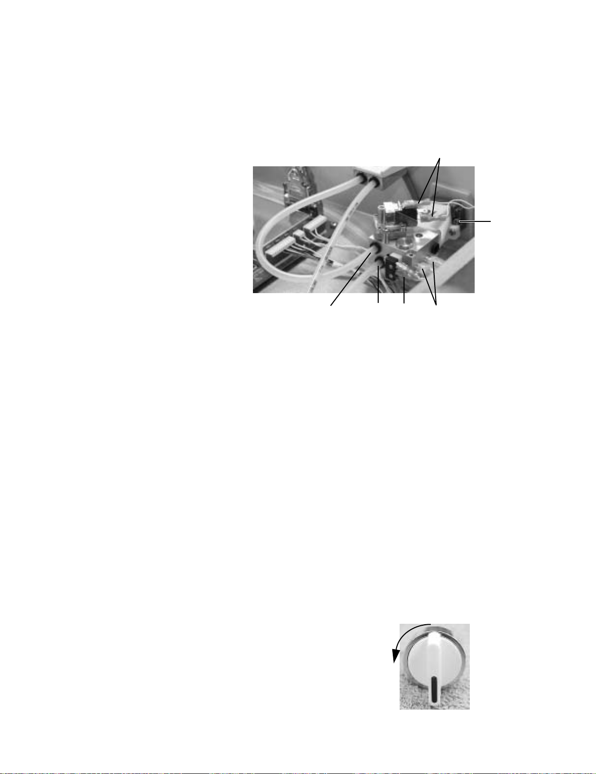
S/5 Aespire
4.11 Replace ACGO selector switch
Removal 1. Remove the tabletop (Section 4.4).
2. Clip the tie wraps (
3. Disconnect the fresh gas (
4. Disconnect the wires from the ACGO mode microswitch (
1) from the outlet barb fittings at the side of the switch.
5
6
3241
2) and flush (3) tubes at the back of the switch.
4) at the back of the selector
switch.
5. Disconnect the wires from the flush pressure switch (5) on top of the selector switch.
6. Set the ACGO selector switch to ABS.
7. Back out the selector switch mounting screws (
6) until the tips are flush with the face
of the mounting casting.
8. While pushing the selector knob toward the machine and holding it steady, push the
valve body toward the knob and rotate it counterclockwise to separate the valve
body from the knob assembly.
9. Remove the knob assembly and protective shroud from the machine.
10. Remove the valve from the silicone output tubes.
Replacement 1. Remove the knob assembly from the valve body.
2. Back out the selector switch mounting screws until the tips are flush with the face of
the mounting casting.
3. Guide the outlet fittings of the valve body into their respective silicone tubes.
4. Hold the selector knob with the
indicator mark facing down. Turn the
chrome collar to its maximum
counterclockwise position (as
viewed from the front).
4-32 07/04 1009-0356-000
Page 95

4 Repair Procedures
5. Place the shroud over the knob and
guide the assembly into the pan
opening.
6. Ensure that the indicators on the
shroud align with label on the pan
and the alignment tab mates with
the alignment hole in the pan.
7. While holding the knob assembly
steady against the pan, place the
valve assembly over the knob
actuator. Using moderate force
press the two assemblies together.
The knob should rotate to the ACGO
position.
8. While continuing to force the
assemblies together, rotate the
knob assembly to the ABS position. The assemblies should snap into place.
Actuator
9. Verify proper alignment of the knob with the setting indicators. Tighten the mounting
screws evenly to secure the switch assembly to the pan.
10. Secure the outlet tubing with tie wraps.
11. Connect the fresh gas and flush gas tubing. Pull on the tubing to ensure that it is
locked in the fitting.
12. Reconnect the wires to the ACGO mode microswitch at the back of the valve
(top two terminals).
13. Reconnect the wires to the flush pressure switch at the top of the valve
(upper and lower terminals).
14. Replace the tabletop.
Test procedure 1. Confirm that flush flow and 5 L/min fresh gas flow are diverted to the ACGO port and
the ABS in the respective knob positions.
2. Confirm that the ventilator display indicates ACGO mode when the valve is set in the
ACGO position.
3. Test the function of the flush pressure switch
(Service Mode - “Display Discrete I/O Signals”).
4. Perform the low-pressure leak test (Section 3.5).
5. Perform the checkout procedure (Section 3)
1009-0356-000 07/04 4-33
Page 96

S/5 Aespire
4.12 Clean or replace ACGO port flapper valve
1. Remove the tabletop (Section 4.4).
2. Remove the ACGO cap mounting
screws.
3. Remove the cap.
4. Examine the flapper and disk for
obstructions or debris. Clean with
isopropyl alcohol if necessary; retest.
5. If leak persists, replace the flapper.
• Remove the flapper from the check
valve disk.
• Clean the new flapper with isopropyl
alcohol.
• Apply a drop of isopropyl alcohol to
the center hub of the new flapper.
• Before the alcohol evaporates, align
the center hub of the new flapper
with the center hole of the check
valve disc.
•While pressing the flapper against
the disc, use you fingernail to help
pull the hub through the disc from
the other side.
6. Lubricate the o-ring sparingly with Krytox (do not get Krytox on the flapper).
Cap
Hub
Flapper
O-ring
7. Insert the flapper assembly into the ACGO outlet with the flapper up.
8. Replace the cap.
4-34 07/04 1009-0356-000
Page 97

4.13 Reconfigure sample gas return line
Sample gas return is directed to the scavenging system as a factory default. Perform
the following to reroute the sample gas back to the breathing system. Refer to “Tubing”
on page 9-8.
1. Remove the tabletop (Section 4.4).
2. Port 4 (A) of the ABS breathing system
is connected to the expiratory circuit,
downstream of the expiratory check
valve. As a factory default, Port 4 is
plumbed with a length of tubing that is
plugged (B) at the far end.
4 Repair Procedures
3. Remove the plug from the tube.
4. Find the sample return line at the leftrear corner of the pan assembly. The
sample return line includes an inline
connector (C) at the point where the
sample line goes down into the vent
engine housing.
5. Separate the scavenging tube,
removing the inline connector from the portion of the tube that extends into the vent
engine housing. Plug the open end of the scavenging tube with the plug removed
above.
6. Insert the inline connector from the sample return port into the open tube to Port 4.
Pull on the connector to ensure that it is securely connected.
7. Replace the tabletop.
8. Perform the checkout procedure (Section 3).
A B
C
1009-0356-000 07/04 4-35
Page 98

S/5 Aespire
4.14 Replace the APL valve
1. Remove the ABS breathing system.
2. The APL valve is held in place with a
spring and a retainer (A) that snaps into
a recess in the lower body of the APL
valve. To release the retainer, place an
appropriately sized straight blade
screwdriver into the housing cutout (B).
Twist the screwdriver to release the
retainer.
3. Place the new APL valve into position
with the setting indicator facing
forward.
4. Place the spring into the retainer.
B
5. While holding the APL valve tight to the
housing, Snap the spring and retainer
onto the valve body from below.
6. Reinstall the ABS breathing system.
7. Perform the checkout procedure (Section 3).
A
4-36 07/04 1009-0356-000
Page 99

4.15 Replace the bag support arm
1. Remove the ABS breathing system from the machine.
2. From the underside of the casting,
remove the two screws/
lockwashers (A) that hold the arm in
place.
4 Repair Procedures
Note: The adjustment nut is
initially set so that 5-mm of
exposed thread extends from
the adjusting nut. With use,
the force required to move the
arm increases and may
require readjustment.
• If either of the pins (see below)
A
remain in the casting, remove
them from the casting.
3. Install the new bag support arm
assembly.
• Position the bag arm over
mounting pattern of 4 small holes
in the support casting. The arm
should extend towards the front of
B
the machine. Align the two pins
(B) extending from the base of the
bag arm assembly, with two of the
small holes in the casting that are
in line with the APL valve.
• Lower the bag arm, pushing the two pins into the holes.
• From the underside of the casting, secure the bag arm with two M3x16 screws and
lockwashers.
4. Test the force required to swing the bag arm from side to side and adjust if necessary.
The force is adjusted by turning the
lock nut (8-mm socket) which is
accessible from underneath the
support casting. Turn clockwise to
C
increase the force and
counterclockwise to reduce the
force.
• Swing the bag arm sideways
through the 90 degree arc
permitted by its internal stop.
• Adjust to just enough friction to prevent the bag arm from swinging sideways as
the bag height is being changed. The bag arm height is changed by squeezing the
lock release lever (C) at the free end of the bag arm and rotating it to the desired
position.
5. Replace the ABS breathing system.
1009-0356-000 07/04 4-37
Page 100

S/5 Aespire
4.15.1 Servicing
the bag support
arm
Service parts for the bag support arm include the upper and lower assemblies.
To replace either assembly:
1. Remove the bag support arm from the machine (Section 4.15).
2. To separate the upper assembly
from the lower assembly, use a
small (2.5-mm) pin punch from the
bottom to drive the dowel pin up and
out.
3. To assemble the bag arm, apply a
light coat of Krytox to the area of the
upper arm (A) that extends into the
lower arm (including the dowel pin
groove).
A
B
C
C
Groove
4. Insert the upper assembly into the lower assembly. Align the surface (B) of the upper
assembly with the surface (C) of the lower assembly.
5. Insert the dowel pin into the hole
(from the top side as shown). Drive
the dowel pin into the bag arm until
it is flush with the top surface.
4-38 07/04 1009-0356-000
 Loading...