

Page 1
GE Healthcare
Girae® OmniBed
Service Manual
To reorder this manual, order kit:
• 6600-0834-801 (USA)
• 6600-0834-802 (INTL)
Copyright 2001 by Datex-Ohmeda, Inc.
All rights reserved.
6600-0343-000 104
Page 2

© 2001 by Datex-Ohmeda, Inc.
All rights reserved. General Electric Company reserves the right to make changes in specications and features
shown herein, or discontinue the product described at any time without notice or obligation. Contact your
GE Representative for the most current information. Girae and Panda® are registered trademarks owned by
Datex-Ohmeda, Inc. GE and GE Monogram are trademarks of General Electric Company. All other company and
product names mentioned may be trademarks of the companies with which they are associated.
Page 3

Table of Contents
About this Manual ........................................................................................................... xv
Scope and Intended Users ....................................................................................................................................xv
Conventions .................................................................................................................................................................. xv
References ..................................................................................................................................................................xvi
Symbol Denitions .................................................................................................................................................... xvi
User Responsibility .................................................................................................................................................xviii
Important ....................................................................................................................................................................xviii
Technical Competence ...........................................................................................................................................xix
Warnings .......................................................................................................................................................................xix
Cautions ........................................................................................................................................................................xx
Chapter 1: Functional Description .................................................................................1
1.1 Control Board .........................................................................................................................................................1
1.2 Relay Board ............................................................................................................................................................3
1.3 Display Driver Board / EL Display .................................................................................................................4
1.4 LED Board .................................................................................................................................................................5
1.5 Power Supply .......................................................................................................................................................... 5
1.6 Peripheral Components ..................................................................................................................................... 5
1.6.1 Rail and Heater Door Switches ........................................................................................................6
1.7 DataLink Option ....................................................................................................................................................6
1.8 Servo Controlled Oxygen Option ...................................................................................................................7
1.9 Humidier ...............................................................................................................................................................9
Chapter 2: Service Checkout .........................................................................................11
2.1 Setup .......................................................................................................................................................................11
2.2 Mechanical Checks ........................................................................................................................................... 11
2.3 Controller Checks............................................................................................................................................... 12
2.4 Humidity Check .................................................................................................................................................. 14
2.5 Servo Controlled Oxygen Check ................................................................................................................. 14
2.5.1 Leak Check ............................................................................................................................................. 14
2.5.2 Pre-use Checkout ................................................................................................................................ 14
2.5.3 Supply Valve Leak Test ..................................................................................................................... 15
© 2001 by Datex-Ohmeda, Inc.. All rights reserved. 6600-0343-000 104 iii
Page 4

Table of Contents
Chapter 3: Calibration and Maintenance ...................................................................21
2.6 Scale Check .......................................................................................................................................................... 16
2.6.1 Mechanical Check ............................................................................................................................... 16
2.6.2 Weight Checks ...................................................................................................................................... 16
2.6.2.1 Center Weight Check ........................................................................................................... 16
2.6.2.2 O Center Weight Check .................................................................................................... 17
2.7 Other Accessory Checks................................................................................................................................. 17
2.8 Cable Connections and Mechanical Controls ...................................................................................... 18
3.1 Service Maintenance Schedule ................................................................................................................... 21
3.2 Special Tools ........................................................................................................................................................ 23
3.3 System Calibration ............................................................................................................................................ 23
3.4 Line Voltage Calibration ................................................................................................................................. 24
3.5 Humidier Calibration ..................................................................................................................................... 25
3.6 Servo Controlled Oxygen Calibration ....................................................................................................... 26
3.7 Scale Calibration ................................................................................................................................................ 26
3.8 Leakage Current ................................................................................................................................................ 27
3.9 Ground Resistance Check.............................................................................................................................. 27
Chapter 4: Troubleshooting ..........................................................................................29
4.1 Startup Sequence .............................................................................................................................................. 29
4.2 Service Screen..................................................................................................................................................... 30
4.3 Alarm Messages ................................................................................................................................................. 34
4.3.1 “Air Probe Failure” Alarm .................................................................................................................. 34
4.3.2 “Air Temp >38C” or “Air Temp >40C” Alarm ............................................................................. 34
4.3.3 “Baby Hot” or “Baby Cold” Alarm ................................................................................................. 34
4.3.4 “Baby Mode Disabled” Alarm ......................................................................................................... 35
4.3.5 “Baby Probe 1 Failure” or “Baby Probe 2 Failure” Alarm ................................................... 35
4.3.6 “Bad Membrane Switch” Alarm .................................................................................................... 35
4.3.7 “Bed Heater Failure” Alarm ............................................................................................................. 36
4.3.8 “Bed Up/Down Pedal Failure” Alarm .......................................................................................... 36
4.3.9 “Bed Up/Down Pedal Switches Disabled” Alarm .................................................................. 36
4.3.10 “Canopy Pedal Disabled” Alarm ................................................................................................. 37
4.3.11 “Canopy Pedal Failure” Alarm ..................................................................................................... 37
4.3.12 “Canopy Pedal Pressed” Alarm ................................................................................................... 37
4.3.13 “Down Pedal Pressed” Alarm ...................................................................................................... 37
4.3.14 “Fan Always in High Speed” Alarm ........................................................................................... 38
4.3.15 “Fan Failure” Alarm .......................................................................................................................... 38
4.3.16 “Heater Doors Not Closed” Alarm ............................................................................................. 39
4.3.17 “Heater Doors Not Opened” Alarm ........................................................................................... 39
4.3.18 “Humidier Failure” Alarm ............................................................................................................ 40
iv 6600-0343-000 104 © 2001 by Datex-Ohmeda, Inc.. All rights reserved.
Page 5

Table of Contents
4.3.19 “In Transition - Heat O” Alarm .................................................................................................. 41
4.3.20 “Motor Drive Failure” Alarm ......................................................................................................... 41
4.3.21 Power Failure (LED Indicator) ...................................................................................................... 42
4.3.22 “Radiant Heater Failure” Alarm .................................................................................................. 42
4.3.23 “Temperature out of Calibration” Alarm ................................................................................ 42
4.3.24 “Up Pedal Pressed” Alarm ............................................................................................................. 43
4.4 Error Codes ........................................................................................................................................................... 43
4.4.1 System Failure 0 ..................................................................................................................................43
4.4.2 System Failure 1 ..................................................................................................................................44
4.4.3 System Failure 2 ..................................................................................................................................44
4.4.4 System Failure 3 ..................................................................................................................................44
4.4.5 System Failure 5 ..................................................................................................................................44
4.4.6 System Failure 6 ..................................................................................................................................45
4.4.7 System Failure 7 ..................................................................................................................................45
4.4.8 System Failure 8 ..................................................................................................................................45
4.4.9 System Failure 11 ................................................................................................................................ 45
4.4.10 System Failure 12 ............................................................................................................................. 46
4.4.11 System Failure 13 ............................................................................................................................. 46
4.4.12 System Failure 14 ............................................................................................................................. 46
4.4.13 System Failure 15 ............................................................................................................................ 46
4.4.14 System Failure 16 ............................................................................................................................ 48
4.4.15 System Failure 17 ............................................................................................................................ 48
4.4.16 System Failure 18 ............................................................................................................................. 48
4.4.17 System Failure 19 ............................................................................................................................. 49
4.4.18 System Failure 20 ............................................................................................................................. 49
4.4.19 System Failure 22 ............................................................................................................................ 49
4.4.20 System Failure 23 ............................................................................................................................ 50
4.4.21 System Failure 25 ............................................................................................................................. 50
4.4.22 System Failure 26 ............................................................................................................................. 50
4.4.23 System Failure 27 ............................................................................................................................. 51
4.4.24 System Failure 28 ............................................................................................................................. 51
4.4.25 System Failure 29 ............................................................................................................................. 51
4.4.26 System Failure 30 ............................................................................................................................. 51
4.4.27 System Failure 33 ............................................................................................................................. 52
4.4.28 System Failure 34 ............................................................................................................................. 52
4.4.29 System Failure 35 ............................................................................................................................. 52
4.4.30 System Failure 36 ............................................................................................................................ 52
4.4.31 System Failure 37 ............................................................................................................................ 53
4.4.32 System Failure 38 ............................................................................................................................ 53
4.4.33 System Failure 50 ............................................................................................................................. 53
4.4.34 System Failure 51 ............................................................................................................................. 53
4.4.35 System Failure 52 ............................................................................................................................. 54
4.4.36 System Failure 53 ............................................................................................................................. 54
4.4.37 System Failure 55 ............................................................................................................................. 54
© 2001 by Datex-Ohmeda, Inc.. All rights reserved. 6600-0343-000 104 v
Page 6

Table of Contents
4.4.38 System Failure 60 ............................................................................................................................ 54
4.4.39 System Failure 98 ............................................................................................................................. 54
4.4.40 System Failure 99 ............................................................................................................................. 54
4.5 Troubleshooting Symptoms ......................................................................................................................... 55
4.6 Additional Troubleshooting Tips ................................................................................................................. 58
4.6.1 Raising and Lowering the Canopy or Elevating Base ......................................................... 58
4.6.2 Incubator Heaters and Bed Safety Thermostat .................................................................... 59
4.6.3 Radiant Heater ..................................................................................................................................... 59
4.6.4 Power Supplies ..................................................................................................................................... 59
4.6.5 Switches/Thermostat ........................................................................................................................ 60
4.6.6 Humidier Heater/Safety Thermostat ....................................................................................... 61
4.6.7 Compartment Air Probe and Patient Probes .......................................................................... 61
4.6.8 Heat Sink Sensor Thermistor .........................................................................................................62
4.6.9 E-base Motor and Canopy Motor ................................................................................................ 62
4.6.10 Rail Lift Belt Failure ........................................................................................................................... 63
4.6.11 Troubleshooting the 50 Pin Ribbon Cable ............................................................................. 64
4.6.12 Troubleshooting the Toroidal Transformer ........................................................................... 64
4.6.13 Interpreting Serial Numbers ........................................................................................................ 64
4.7 Servo Controlled Oxygen ............................................................................................................................... 65
4.7.1 Servo Controlled Oxygen Service Screen ................................................................................. 65
4.7.2 Servo Controlled Oxygen Alarm Messages ............................................................................. 66
4.7.3 Servo Controlled Oxygen Troubleshooting Tips .................................................................... 69
4.7.3.1 Check Supply Valves and Endcap Safety Valve ....................................................... 69
4.7.3.2 Check Calibration Valve/Calibration Fan .................................................................... 69
4.7.3.3 Check Cooling Fan ................................................................................................................. 70
4.7.3.4 Sensor Housing Temperature Sensor Temperature to Resistance Curve ... 70
Chapter 5: Repair Procedures .......................................................................................71
5.1 Canopy Removal for Replacement .......................................................................................................... 71
5.2 Servicing the Canopy Seals ........................................................................................................................ 76
5.2.1 Servicing Original Canopy Seals ................................................................................................... 77
5.2.2 Servicing Enhanced Canopy Seals .............................................................................................. 89
5.3 Porthole Door Replacement ........................................................................................................................ 90
5.4 Right Rail Assembly Repair Procedures .................................................................................................. 90
5.4.1 Removing the Right Upright (Motor Side) ................................................................................. 90
5.4.2 Removing the Left Upright .............................................................................................................. 94
5.4.3 Right Rail Internal Repairs ............................................................................................................... 96
5.4.3.1 Removing the Inner Rail Assembly ................................................................................ 96
5.4.3.2 Replacing Rollers and Tension Springs ........................................................................ 97
5.4.3.3 Separating the Lift Rail from the Belt Channel ......................................................... 98
5.4.3.4 Replacing the Rail Drive Belt ............................................................................................. 98
5.4.3.5 Replacing the Rail Buoyancy Springs ........................................................................... 99
5.4.3.6 Replacing the Slip Clutch or Motor Roll Pin ..............................................................100
vi 6600-0343-000 104 © 2001 by Datex-Ohmeda, Inc.. All rights reserved.
Page 7

Table of Contents
5.4.4 Reassembling the Right Upright ................................................................................................100
5.5 Left Rail Internal Repairs ..............................................................................................................................102
5.5.1 Removing the Inner Rail Assembly ............................................................................................102
5.5.2 Replacing the Rail Buoyancy Springs ......................................................................................103
5.5.3 Replacing Rollers, Tension Springs, and Cable Carrier Links .........................................104
5.5.4 Reassembling the Left Upright ...................................................................................................104
5.5.5 Replacement of the Left Upright Heater Wire Harness/Cable Carrier Assembly 106
5.5.5.1 Removing and Disassembling the Rail ......................................................................106
5.5.5.2 Removing the Old Harness Assembly from the Left Rail ...................................106
5.5.5.3 Reinstalling the New Harness on the Left Rail .......................................................108
5.5.5.4 Removing the Old Harness from the Cable Carrier Channel ...........................109
5.5.5.5 Installing the New Harness on the Cable Carrier Channel ...............................109
5.5.5.6 Reassembly ............................................................................................................................111
5.6 Radiant Heater Assembly Repair Procedures ....................................................................................111
5.6.1 Removing the Canopy/Heater Assembly ...............................................................................111
5.6.1.1 Realigning the Canopy ......................................................................................................113
5.6.2 Replacing the Radiant Heater .....................................................................................................114
5.6.3 Heater Door Spool Assembly .......................................................................................................116
5.6.4 Heater Door Cable Adjustment...................................................................................................117
5.6.5 Spring Tube Assembly Replacement ........................................................................................118
5.7 Compartment Air Probe Repairs .............................................................................................................121
5.8 Removing the Upper End Cap Spring ...................................................................................................122
5.9 Lower Unit Repairs ..........................................................................................................................................123
5.9.1 Removing the Chassis Cover with the Storage Drawer in Place .................................123
5.9.2 Incubator Fan, Fan Motor, and Optical Fan Sensor ...........................................................124
5.9.3 Incubator Heater Replacement ..................................................................................................126
5.9.3.1 To Remove the Incubator Heater Closest to the Foot of the Bed .................127
5.9.3.2 To Remove the Incubator Heater Closest to the Head of the Bed................127
5.9.4 Elevating Base ....................................................................................................................................128
5.9.5 Chassis Replacement ......................................................................................................................129
5.9.6 Bed Up/Down Pedal Switch ..........................................................................................................130
5.9.7 Canopy Pedal Switch ......................................................................................................................130
5.9.8 Canopy Membrane Switch Replacement ..............................................................................130
5.10 Bed Tilt Brake Pad Replacement ..........................................................................................................132
5.11 Caster Replacement ...................................................................................................................................133
5.12 Humidier Assembly Repairs...................................................................................................................133
5.12.1 Tips for Repairing an Old Style Unit ........................................................................................134
5.12.2 Disassembly ......................................................................................................................................134
5.12.3 Reassembly .......................................................................................................................................136
5.13 Controller and Display Module Procedures ......................................................................................137
5.13.1 Display Module ................................................................................................................................137
5.13.2 Probe Panel .......................................................................................................................................138
© 2001 by Datex-Ohmeda, Inc.. All rights reserved. 6600-0343-000 104 vii
Page 8

Table of Contents
5.13.2.1 Battery ....................................................................................................................................139
5.13.3 Controller Components ................................................................................................................140
5.13.3.1 Control Board ......................................................................................................................141
5.13.3.2 Relay Board ..........................................................................................................................141
5.13.3.3 Solid State Relays ..............................................................................................................141
5.13.3.4 Power Supply ......................................................................................................................141
5.13.3.5 Toroidal Transformer .......................................................................................................142
5.13.3.6 Canopy Lift Motor, ISO Transformer, Circuit Breakers, Power Switches, and
Power Outlets ...................................................................................................................142
5.14 Servo Controlled Oxygen Service Procedures .................................................................................143
5.14.1 Installing Oxygen Sensors ..........................................................................................................143
5.14.2 Replacing the Vent Screen .........................................................................................................143
5.14.3 Sensor Housing Repairs ..............................................................................................................144
5.14.3.1 Sensor Housing Repairs: Boards, Calibration Fan Assembly, and Sensor
Plug Assembly ..................................................................................................................144
5.14.3.2 Sensor Housing Repairs: Calibration Valve ...........................................................145
5.14.4 Valve Housing Repairs .................................................................................................................146
5.14.4.1 Valve Housing Repairs: Regulator Assembly ........................................................146
5.14.4.2 Valve Housing Repairs: Supply Valves ...................................................................147
5.14.5 Endcap Safety Valve......................................................................................................................147
5.14.6 Servo Oxygen Board Repairs ....................................................................................................148
Chapter 6: Illustrated Parts .........................................................................................149
6.1 Exploded Views .................................................................................................................................................149
6.1.1 Probe Housing, Display Module, and Electrical Enclosure .............................................150
6.1.2 Bed and Side Panels.........................................................................................................................158
6.1.3 Radiant Heater and Canopy ........................................................................................................164
6.1.4 Chassis ...................................................................................................................................................172
6.1.5 Humidier .............................................................................................................................................176
6.1.6 Elevating Base ....................................................................................................................................178
6.1.7 Uprights and Lift Rail Components ...........................................................................................180
6.1.8 Compartment Air Probe ................................................................................................................192
6.1.9 Servo Control Oxygen .....................................................................................................................194
6.1.10 Storage Drawer ...............................................................................................................................202
6.2 Accessories .........................................................................................................................................................211
6.3 Labels ....................................................................................................................................................................212
6.4 PCB Layouts .......................................................................................................................................................217
6.5 Wiring Diagrams ..............................................................................................................................................221
Appendix A: Compartment and Skin Probe Characteristics .................................233
Appendix B: Specications ..........................................................................................235
B.1 Power Requirements......................................................................................................................................235
viii 6600-0343-000 104 © 2001 by Datex-Ohmeda, Inc.. All rights reserved.
Page 9

Table of Contents
B.2 Accessory Outlets ............................................................................................................................................235
B.3 Standards ............................................................................................................................................................235
B.4 Operating Environment ................................................................................................................................236
B.5 Storage Conditions .........................................................................................................................................236
B.6 User Control Settings .....................................................................................................................................236
B.7 Alarms ...................................................................................................................................................................236
B.8 Performance ......................................................................................................................................................237
B.8.1 System ....................................................................................................................................................237
B.8.2 Humidity ................................................................................................................................................237
B.8.3 Servo Control Oxygen .....................................................................................................................237
B.9 Weight Scale ......................................................................................................................................................238
B.10 Mechanical Specications ........................................................................................................................238
B.10.1 Accessories........................................................................................................................................238
Appendix C: RS-232 Serial Data ..................................................................................239
C.1 RS-232 Connector ...........................................................................................................................................239
C.2 Data Stream .......................................................................................................................................................239
C.3 Nurse Call ............................................................................................................................................................240
© 2001 by Datex-Ohmeda, Inc.. All rights reserved. 6600-0343-000 104 ix
Page 10

Table of Contents
x 6600-0343-000 104 © 2001 by Datex-Ohmeda, Inc.. All rights reserved.
Page 11

List of Figures
Figure 1-1 Block Diagram ........................................................................................................................................2
Figure 1-2 Humidier .................................................................................................................................................9
Figure 2-1 Connections and Controls .............................................................................................................. 18
Figure 3-1 Control Board Test Points ............................................................................................................... 22
Figure 4-1 First Service Screen ........................................................................................................................... 30
Figure 4-2 Second Service Screen .................................................................................................................... 31
Figure 4-3 Status Menu .......................................................................................................................................... 31
Figure 4-4 Switch Diagnostic Diagram ........................................................................................................... 32
Figure 4-5 Pedal Screen ......................................................................................................................................... 32
Figure 4-6 Service Screen ..................................................................................................................................... 33
Figure 4-7 Servo Controlled Oxygen Service Screen ................................................................................ 65
Figure 5-1 Heater Housing Cover and Sot ................................................................................................ 72
Figure 5-2 Original Seal Parts .............................................................................................................................. 73
Figure 5-3 Nuts........................................................................................................................................................... 73
Figure 5-4 Access Holes ......................................................................................................................................... 74
Figure 5-5 Canopy, Bracket, and Heater Housing..................................................................................... 74
Figure 5-6 Two People Needed for this Step ................................................................................................ 75
Figure 5-7 Canopy Seals and Extrusions ....................................................................................................... 76
Figure 5-8 Wedging a Blunt Object to Keep Seal Open .......................................................................... 77
Figure 5-9 Enhanced Seal Parts ......................................................................................................................... 78
Figure 5-10 West Side Seal Parts....................................................................................................................... 79
Figure 5-11 Using North Seal to Help Position Washers ........................................................................ 79
Figure 5-12 Seal Cross-section ........................................................................................................................... 80
Figure 5-13 North Seal Parts ............................................................................................................................... 81
Figure 5-14 Beveled Side of North Spacer Toward Canopy .................................................................. 81
Figure 5-15 Hole Fill Assembly (2x) for Canopies with Six Holes across North End ................... 82
Figure 5-16 South Seal Parts ............................................................................................................................... 83
Figure 5-17 South Corner Parts .......................................................................................................................... 84
Figure 5-18 North Corner Parts .......................................................................................................................... 84
Figure 5-19 Installing Rail Spacers.................................................................................................................... 85
Figure 5-21 Sot ....................................................................................................................................................... 87
© 2001 by Datex-Ohmeda, Inc.. All rights reserved. 6600-0343-000 104 xi
Page 12

List of Figures
Figure 5-22 Trimming the Sot.......................................................................................................................... 87
Figure 5-23 Untrimmed and Trimmed Sot ................................................................................................ 88
Figure 5-24 Disconnecting Heater Door Cable ........................................................................................... 91
Figure 5-25 Upright Decorative Strips, End Caps, and Wire Covers .................................................. 92
Figure 5-26 Removing the Lift Motor ............................................................................................................... 93
Figure 5-27 Display Module Disassembly ...................................................................................................... 93
Figure 5-28 Right Upright Disassembly .......................................................................................................... 96
Figure 5-29 Rollers and Tensioning Spring ................................................................................................... 97
Figure 5-30 Replacing the Drive Belt ............................................................................................................... 98
Figure 5-31 Replacing the Rail Buoyancy Springs ..................................................................................... 99
Figure 5-32 Left Inner Rail ...................................................................................................................................102
Figure 5-33 Left Rail Springs and Spools .....................................................................................................103
Figure 5-34 Re-attaching the Upright ...........................................................................................................104
Figure 5-35 Cable Guard Latch ........................................................................................................................107
Figure 5-36 3-pin MAT-N-LOK Connector and Bushing ........................................................................107
Figure 5-37 Cable Tie ............................................................................................................................................108
Figure 5-38 Connector Drawing ......................................................................................................................109
Figure 5-39 Opened Cable Guard Latches ..................................................................................................109
Figure 5-40 Correct and Incorrect Cable Tie Usage ...............................................................................110
Figure 5-41 Lift Rail and Cable Carrier Channel Together ..................................................................110
Figure 5-42 Canopy Alignment .........................................................................................................................112
Figure 5-43 Radiant Heater Disassembly ....................................................................................................114
Figure 5-44 Heater Door Cable Adjustment ...............................................................................................116
Figure 5-45 Securing String to the Spring Tube ........................................................................................118
Figure 5-46 Removal of the Lower M5 Nut .................................................................................................119
Figure 5-47 Dog Point of the Set Screw ........................................................................................................120
Figure 5-48 Compartment Air Probe Disassembly ..................................................................................121
Figure 5-49 Top Rail End Cap ............................................................................................................................122
Figure 5-50 Bed Disassembly ............................................................................................................................124
Figure 5-51 Heat Sink and Fan .........................................................................................................................125
Figure 5-52 Fan Motor ..........................................................................................................................................125
Figure 5-53 Elevating Base .................................................................................................................................126
Figure 5-54 Chassis Bottom Cover .................................................................................................................129
Figure 5-55 Replacing the Tilt Brake Pad .....................................................................................................132
Figure 5-56 Humidier Parts ..............................................................................................................................135
Figure 5-57 Display Module ...............................................................................................................................137
Figure 5-58 Probe Panel ......................................................................................................................................138
xii 6600-0343-000 104 © 2001 by Datex-Ohmeda, Inc.. All rights reserved.
Page 13

List of Figures
Figure 5-59 Electronics Enclosure ...................................................................................................................140
Figure 5-60 Installing Sensors ...........................................................................................................................143
Figure 5-61 Sensor Housing...............................................................................................................................144
Figure 5-62 Valve Housing..................................................................................................................................146
Figure 5-63 Endcap Safety Valve .....................................................................................................................147
Figure 6-1 Probe Panel Assembly ....................................................................................................................151
Figure 6-2 Display Module ..................................................................................................................................153
Figure 6-3 Electrical Enclosure .........................................................................................................................155
Figure 6-4 Humidier Transformer and RS232 Option ..........................................................................157
Figure 6-5 Bed .........................................................................................................................................................159
Figure 6-6 Side Panel (East/West)....................................................................................................................161
Figure 6-7 Rear (North) and Front (South) Wall .........................................................................................163
Figure 6-8 Radiant Heater ..................................................................................................................................165
Figure 6-9 Canopy .................................................................................................................................................167
Figure 6-10 Original Canopy Seal Parts........................................................................................................168
Figure 6-11 Enhanced Canopy Seal Parts ...................................................................................................169
Figure 6-12 Heater Doors ..................................................................................................................................171
Figure 6-13 Upper Chassis ................................................................................................................................173
Figure 6-14 Lower Chassis ................................................................................................................................175
Figure 6-15 Humidier Assembly ....................................................................................................................177
Figure 6-16 Base and Elevating Column ......................................................................................................179
Figure 6-17 Right (East) Upright Parts, Motor Side (Complete East Rail Assembly: 6600-0290-850)
181
Figure 6-18 Belt Channel - 1 (Lift Motor Side) ............................................................................................183
Figure 6-19 Belt Channel - 2 (Lift Motor Side) ............................................................................................185
Figure 6-20 Lift Rail (Both Sides) .......................................................................................................................187
Figure 6-21 Rail End Caps ..................................................................................................................................189
Figure 6-22 Left (West) Upright (Complete West Rail Assembly: 6600-0290-851) ...................191
Figure 6-23 Compartment Air Probe..............................................................................................................193
Figure 6-24 Servo Control Oxygen Sensor Housing Assembly (Servo O2 Upgrade Kit 6600-0678-800)
195
Figure 6-25 Servo Control Oxygen Valve Housing .................................................................................197
Figure 6-26 Expansion Chamber/Heatsink Vent ......................................................................................198
Figure 6-27 Servo Control Oxygen Cooling Fan ........................................................................................199
Figure 6-28 Servo Control Oxygen PC Board .............................................................................................200
Figure 6-29 Manifold Endcap Safety Valve .................................................................................................201
Figure 6-30 Storage Drawer .............................................................................................................................202
© 2001 by Datex-Ohmeda, Inc.. All rights reserved. 6600-0343-000 104 xiii
Page 14

List of Figures
Figure 6-31 Instrument Shelf (6600-0865-700) ........................................................................................203
Figure 6-32 Monitor Shelf (6600-0824-800) ...............................................................................................204
Figure 6-33 E-Cylinder Holder (6600-0836-800).......................................................................................205
Figure 6-34 Tubing Management Arm (6600-0837-800) .....................................................................206
Figure 6-35 Dovetail Mount DIN Rail (6600-0659-803) ........................................................................207
Figure 6-36 Silo Support Assembly (6600-0853-800) ............................................................................208
Figure 6-37 Rotating I.V. Pole Assembly (6600-0851-800) ...................................................................209
Figure 6-38 Dovetail Extension (6600-0852-800) ...................................................................................210
Figure 6-39 Control Board (6600-0212-850) ..............................................................................................217
Figure 6-40 Display Driver Board (6600-0213-850) ................................................................................218
Figure 6-41 Relay Board (6600-0214-850) Revision Level 10 or Higher ........................................219
Figure 6-42 Relay Board (6600-0214-850) Revision Level 9 or Lower............................................220
Figure 6-43 Wiring Diagram: Control Board ...............................................................................................221
Figure 6-44 Wiring Diagram: Elevating Base and Canopy Lift Rails................................................222
Figure 6-45 Wiring Diagram: Electrical Enclosure ..................................................................................223
Figure 6-46 Wiring Diagram: Graphics Display .........................................................................................224
Figure 6-47 Wiring Diagram: Incubator Relay Board Rev 10 or Higher .......................................225
Figure 6-48 Wiring Diagram: Incubator Relay Board 9 or Lower ....................................................226
Figure 6-49 Wiring Diagram: Radiant Heater Relay Board 10 or Higher ......................................227
Figure 6-50 Wiring Diagram: Radiant Heater Relay Board 9 or Lower .........................................228
Figure 6-51 Wiring Diagram: Servo Humidier Relay Board 10 or Higher ..................................229
Figure 6-52 Wiring Diagram: Servo Humidier Relay Board 9 or Lower .....................................230
Figure 6-53 Wiring Diagram: Servo Control Oxygen ..............................................................................231
xiv 6600-0343-000 104 © 2001 by Datex-Ohmeda, Inc.. All rights reserved.
Page 15

About this Manual
Scope and Intended Users
This service manual describes the repair and maintenance of the Girae OmniBed.
The intended users for this service manual are authorized service personnel.
Conventions
Various types of pictures or icons are used in this service manual wherever they reinforce the printed message
to alert you to potential safety hazards in one of the following ways:
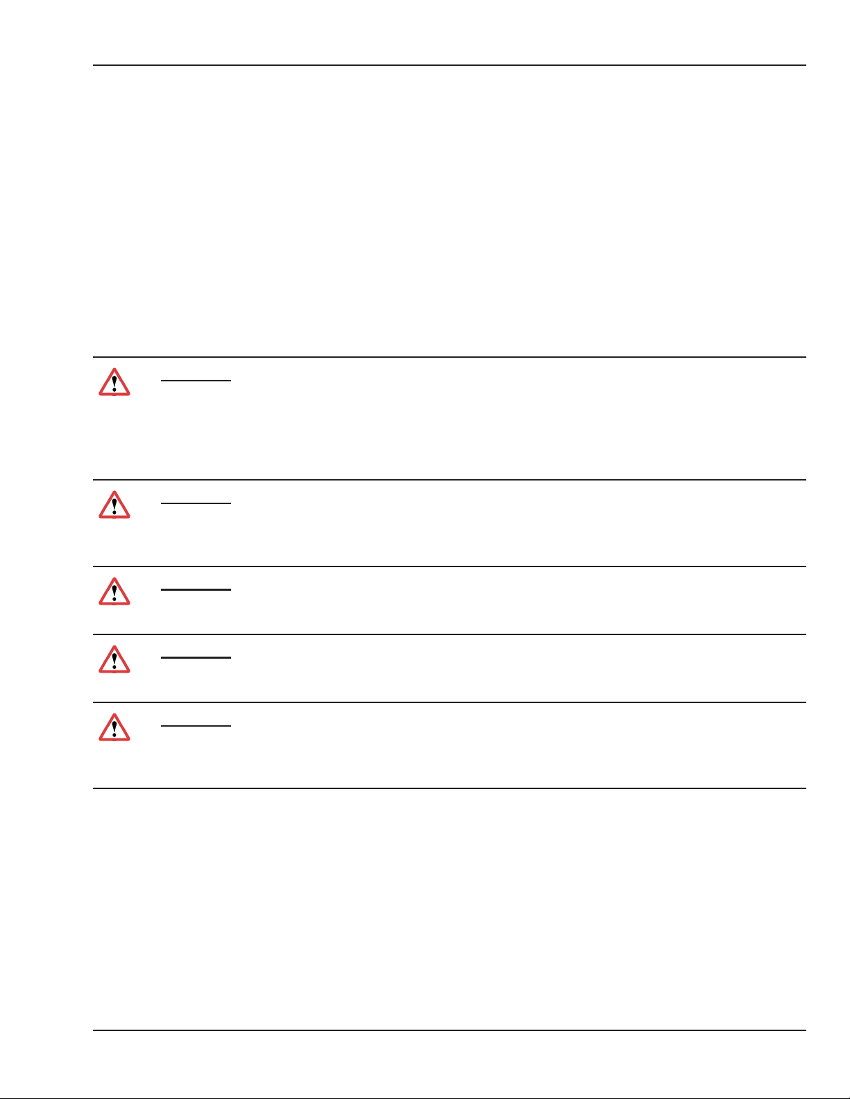
WARNING:
A WARNING statement is used when the possibility of injury to the patient or the operator exists.
CAUTION:
A CAUTION statement is used when the possibility of damage to the equipment exists.
SENSITIVE TO ELECTROSTATIC DISCHARGE CAUTION
An Electrostatic Discharge (ESD) Susceptibility symbol is displayed to alert service personnel that the
part(s) are sensitive to electrostatic discharge and that static control procedures must be used to
prevent damage to the equipment.
NOTE: A note provides additional information to clarify a point in the text.
IMPORTANT: An Important statement is similar to a note, but is used for greater emphasis.
© 2001 by Datex-Ohmeda, Inc.. All rights reserved. 6600-0343-000 104 xv
Page 16
About this Manual
Temp alarm
Heater
Temp alarm
c
37
Airflow curtain
Heater
Temp alarm
c
37
Airflow curtain
Fan
Heater
Temp alarm
c
37
Canopy up / down (used in conjunction with up/down arrows)
Used on Giraffe Humidifier Reservoir
MAX
Max water level for humidifier
Power disconnect
Ground
Used on all electrical equipment
Airflow curtain
Fan
Heater
Temp alarm
c
37
Canopy up / down (used in conjunction with up/down arrows)
Environmental Probe
Airflow curtain
Fan
Heater
Temp alarm
c
37
References
The following table lists the part numbers for the manual kit in each language containing the Girae OmniBed
Operation and Maintenance Manual and other documents pertaining to Girae OmniBed:
Language Manual Kit
Czech M1141763
Danish 6600-0835-817
Dutch 6600-0835-810
English UK 6600-0835-812
English US 6600-0835-801
Estonian M1141752
French 6600-0835-802
German 6600-0835-804
Italian 6600-0835-805
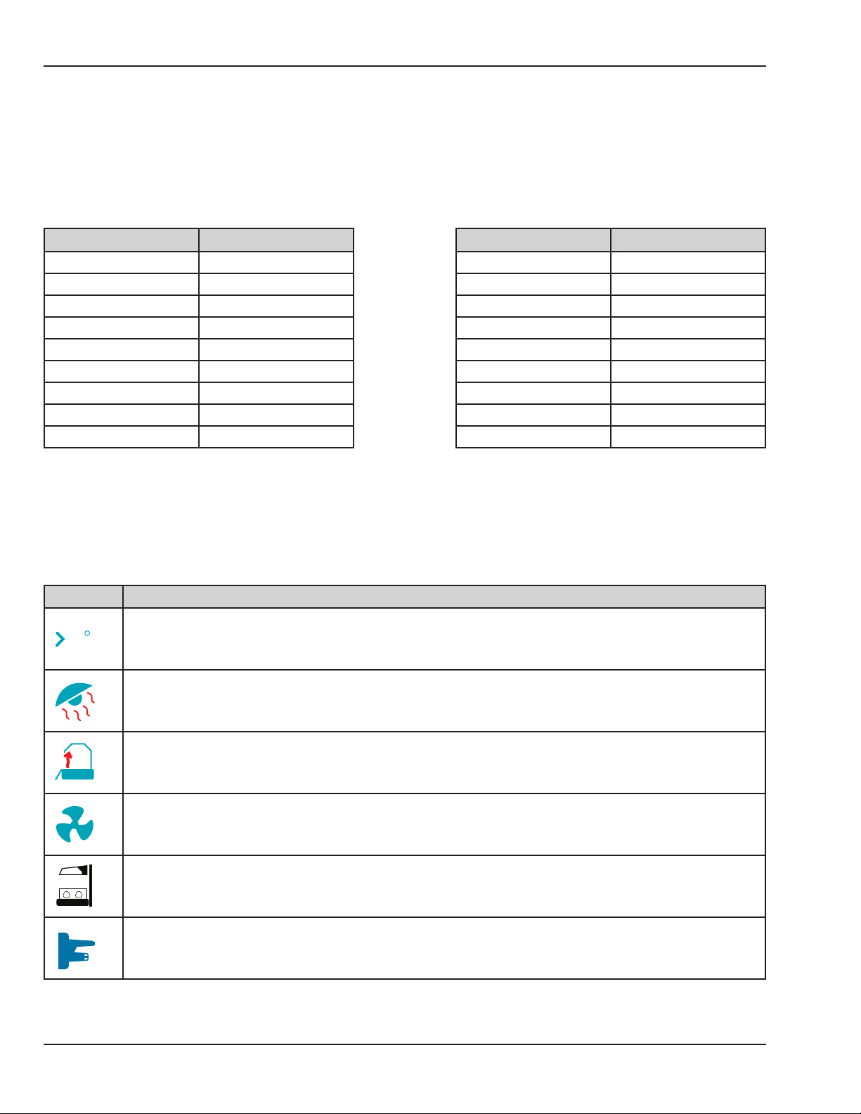
Symbol Denitions
This section identies the symbols that are displayed on the Girae OmniBed:
Symbol Description
37
Temperature Alarm
c
Language Manual Kit
Japanese 6600-0835-807
Korean M1141805
Norwegian 6600-0835-818
Polish M1141760
Romanian M1141768
Russian M1141766
Spanish 6600-0835-803
Swedish 6600-0835-806
Turkish M1141750
Heater
Airow Curtain
xvi 6600-0343-000 104 © 2001 by Datex-Ohmeda, Inc.. All rights reserved.
Fan
Canopy Up/Down (used in conjunction with up/down arrows)
Environmental Probe
Page 17
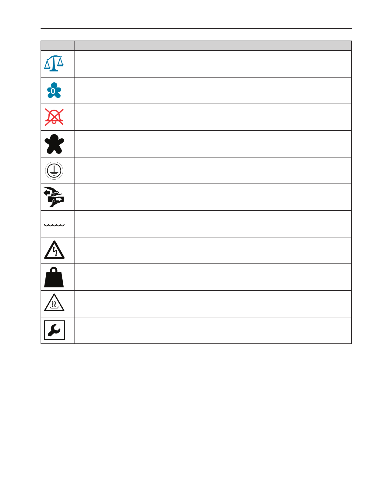
Symbol Description
Canopy up / down (used in conjunction with up/down arrows)
Environmental Probe
Scale
Airflow curtain
Fan
Heater
Temp alarm
c
37
Canopy up / down (used in conjunction with up/down arrows)
Environmental Probe
Scale
Patient O2
Airflow curtain
Fan
Heater
Temp alarm
c
37
Alarm Silence
Canopy up / down (used in conjunction with up/down arrows)
Environmental Probe
Scale
2
Patient O2
Airflow curtain
Fan
Heater
Temp alarm
c
37
Alarm Silence
Patient
Canopy up / down (used in conjunction with up/down arrows)
Environmental Probe
Scale
2
Patient O2
Airflow curtain
Fan
Heater
Temp alarm
c
Ground
Used on Giraffe Humidifier Reservoir
Ground
Used on all electrical equipment
Used on Giraffe Humidifier Reservoir
Max water level for humidifier
Ground
Used on all electrical equipment
Used on Giraffe Humidifier Reservoir
MAX
Max water level for humidifier
Power disconnect
Ground
Used on all electrical equipment
Used on Giraffe Humidifier Reservoir
MAX
Max water level for humidifier
Power disconnect
Maximum weight (of accessories on rail)
Ground
Used on all electrical equipment
22 Kg
MAX.
Caution: Hot surface
Used on Giraffe Humidifier Reservoir
MAX
Max water level for humidifier
Power disconnect
Maximum weight (of accessories on rail)
Ground
Used on all electrical equipment
Used on Giraffe OB heater head,
humidifier
Set up screen
Scale
About this Manual
2
Patient Oxygen
Alarm Silence
Patient
MAX
Protective Ground
Opening Girae Humidier Reservoir
Maximum Water Level for Humidier
Power Disconnect
22 Kg
MAX.
Maximum Weight
Caution: Hot Surface
Setup Screen
© 2001 by Datex-Ohmeda, Inc.. All rights reserved. 6600-0343-000 104 xvii
Page 18

About this Manual
User Responsibility
This Product will perform in conformity with the description thereof contained in this service manual and
accompanying labels and/or inserts, when assembled, operated, maintained and repaired in accordance with
the instructions provided. This Product must be checked periodically. A defective Product should not be used.
Parts that are broken, missing, plainly worn, distorted or contaminated should be replaced immediately. Should
such repair or replacement become necessary, GE Healthcare recommends that a telephone or written request
for service advice be made to the nearest GE Healthcare Regional Service Center. This Product or any of its
parts should not be repaired other than in accordance with written instructions provided by GE Healthcare
and by GE Healthcare trained personnel. The Product must not be altered without GE Healthcare’s prior written
approval. The user of this Product shall have the sole responsibility for any malfunction that results from
improper use, faulty maintenance, improper repair, damage or alteration by anyone other than GE Healthcare..
Important
The information contained in this service manual pertains only to those models of products which are
marketed by GE Healthcare as of the eective date of this manual or the latest revision thereof. This service
manual was prepared for exclusive use by GE Healthcare service personnel in light of their training and
experience as well as the availability to them of parts, proper tools and test equipment. Consequently, GE
Healthcare provides this service manual to its customers purely as a business convenience and for the
customer’s general information only without warranty of the results with respect to any application of such
information.
Furthermore, because of the wide variety of circumstances under which maintenance and repair activities
may be performed and the unique nature of each individual’s own experience, capacity, and qualications,
the fact that a customer has received such information from GE Healthcare does not imply in anyway that
GE Healthcare deems said individual to be qualied to perform any such maintenance or repair service.
Moreover, it should not be assumed that every acceptable test and safety procedure or method, precaution,
tool, equipment or device is referred to within, or that abnormal or unusual circumstances, may not warrant or
suggest dierent or additional procedures or requirements.
This manual is subject to periodic review, update and revision. Customers are cautioned to obtain and consult
the latest revision before undertaking any service of the equipment.
CAUTION:
Servicing of this product in accordance with this service manual should never be undertaken in the
absence of proper tools, test equipment and the most recent revision to this service manual which
is clearly and thoroughly understood.
xviii 6600-0343-000 104 © 2001 by Datex-Ohmeda, Inc.. All rights reserved.
Page 19
About this Manual
Technical Competence
The procedures described in this service manual should be performed by trained and authorized personnel
only. Maintenance should only be undertaken by competent individuals who have a general knowledge of
and experience with devices of this nature. No repairs should ever be undertaken or attempted by anyone
not having such qualications. Genuine replacement parts manufactured or sold by GE Healthcare must be
used for all repairs. Read completely through each step in every procedure before starting the procedure; any
exceptions may result in a failure to properly and safely complete the attempted procedure.
Warnings
WARNING:
Before using the OmniBed, read through this entire manual. As with all medical equipment,
attempting to use this device without a thorough understanding of its operation may result in
patient or user injury. This device should only be operated by personnel trained in its operation
under the direction of qualied medical personnel familiar with the risks and benets of this type of
device. Additional precautions specic to certain procedures are found in the text of this manual.
WARNING:
Complete the Pre-use Checkout chapter of the Operation and Maintenance manual before putting
the unit into operation. If the incubator fails any portion of the checkout procedure it must be
removed from use and repaired.
WARNING:
Do not use the OmniBed in the presence of ammable anesthetics; an explosion hazard exists
under these conditions.
WARNING:
Always disconnect the power before performing service or maintenance procedures detailed in this
manual. Apply power only if you are specically instructed to do so as part of the procedure.
WARNING:
Thoroughly air dry the incubator after cleaning it with ammable agents. Small amounts of
ammable agents, such as ether, alcohol or similar cleaning solvents left in the incubator can cause
a re.
© 2001 by Datex-Ohmeda, Inc.. All rights reserved. 6600-0343-000 104 xix
Page 20

About this Manual
Cautions
CAUTION:
Only competent individuals trained in the repair of this equipment should attempt to service it as
detailed in this manual.
CAUTION:
Detailed information for more extensive repairs is included in the service manual solely for
the convenience of users having proper knowledge, tools and test equipment, and for service
representatives trained by GE Healthcare.
xx 6600-0343-000 104 © 2001 by Datex-Ohmeda, Inc.. All rights reserved.
Page 21
ПРЕДУПРЕЖДЕНИЕ
Това упътване за работа е налично само на английски език.
About this Manual
(BG)
(ZH-CN)
(ZH-HK)
• Ако доставчикът на услугата на клиента изиска друг език, задължение на клиента е да
осигури превод.
• Не използвайте оборудването, преди да сте се консултирали и разбрали упътването за
работа.
• Неспазването на това предупреждение може да доведе до нараняване на доставчика на
услугата, оператора или пациентa в резултат на токов удар, механична или друга опасност.
警告
本维修手册仅提供英文版本。
• 如果客户的维修服务人员需要非英文版本,则客户需自行提供翻译服务。
• 未详细阅读和完全理解本维修手册之前,不得进行维修。
• 忽略本警告可能对维修服务人员、操作人员或患者造成电击、机械伤害或其他形式的伤害。
警告
本服務手冊僅提供英文版本。
• 倘若客戶的服務供應商需要英文以外之服務手冊,客戶有責任提供翻譯服務。
• 除非已參閱本服務手冊及明白其內容,否則切勿嘗試維修設備。
• 不遵從本警告或會令服務供應商、網絡供應商或病人受到觸電、機械性或其他的危險。
警告
本維修手冊僅有英文版。
(ZH-TW)
(HR)
(CS)
• 若客戶的維修廠商需要英文版以外的語言,應由客戶自行提供翻譯服務。
• 請勿試圖維修本設備,除非您已查閱並瞭解本維修手冊。
• 若未留意本警告,可能導致維修廠商、操作員或病患因觸電、機械或其他危險而受傷。
UPOZORENJE
Ovaj servisni priručnik dostupan je na engleskom jeziku.
• Ako davatelj usluge klijenta treba neki drugi jezik, klijent je dužan osigurati prijevod.
• Ne pokušavajte servisirati opremu ako niste u potpunosti pročitali i razumjeli ovaj servisni
priručnik.
• Zanemarite li ovo upozorenje, može doći do ozljede davatelja usluge, operatera ili pacijenta
uslijed strujnog udara, mehaničkih ili drugih rizika.
VÝSTRAHA
Tento provozní návod existuje pouze v anglickém jazyce.
• V případě, že externí služba zákazníkům potřebuje návod v jiném jazyce, je zajištění překladu do
odpovídajícího jazyka úkolem zákazníka.
• Nesnažte se o údržbu tohoto zařízení, aniž byste si přečetli tento provozní návod a pochopili
jeho obsah.
• V případě nedodržování této výstrahy může dojít k poranění pracovníka prodejního servisu,
obslužného personálu nebo pacientů vlivem elektrického proudu, respektive vlivem
mechanických či jiných rizik.
© 2001 by Datex-Ohmeda, Inc.. All rights reserved. 6600-0343-000 104 xxi
Page 22
About this Manual
ADVARSEL
Denne servicemanual ndes kun på engelsk.
(DA)
(NL)
(EN)
• Hvis en kundes tekniker har brug for et andet sprog end engelsk, er det kundens ansvar at
sørge for oversættelse.
• Forsøg ikke at servicere udstyret uden at læse og forstå denne servicemanual.
• Manglende overholdelse af denne advarsel kan medføre skade på grund af elektrisk stød,
mekanisk eller anden fare for teknikeren, operatøren eller patienten.
WAARSCHUWING
Deze onderhoudshandleiding is enkel in het Engels verkrijgbaar.
• Als het onderhoudspersoneel een andere taal vereist, dan is de klant verantwoordelijk voor de
vertaling ervan.
• Probeer de apparatuur niet te onderhouden alvorens deze onderhoudshandleiding werd
geraadpleegd en begrepen is.
• Indien deze waarschuwing niet wordt opgevolgd, zou het onderhoudspersoneel, de operator
of een patiënt gewond kunnen raken als gevolg van een elektrische schok, mechanische of
andere gevaren.
WARNING:
This service manual is available in English only.
• If a customer’s service provider requires a language other than English, it is the customer’s
responsibility to provide translation services.
• Do not attempt to service the equipment unless this service manual has been consulted and is
understood.
• Failure to heed this warning may result in injury to the service provider, operator, or patient from
electric shock, mechanical hazards, or other hazards.
HOIATUS
See teenindusjuhend on saadaval ainult inglise keeles
(ET)
• Kui klienditeeninduse osutaja nõuab juhendit inglise keelest erinevas keeles, vastutab klient
tõlketeenuse osutamise eest.
• Ärge üritage seadmeid teenindada enne eelnevalt käesoleva teenindusjuhendiga tutvumist ja
sellest aru saamist.
• Käesoleva hoiatuse eiramine võib põhjustada teenuseosutaja, operaatori või patsiendi
vigastamist elektrilöögi, mehaanilise või muu ohu tagajärjel.
VAROITUS
Tämä huolto-ohje on saatavilla vain englanniksi.
(FI)
• Jos asiakkaan huoltohenkilöstö vaatii muuta kuin englanninkielistä materiaalia, tarvittavan
käännöksen hankkiminen on asiakkaan vastuulla.
• Älä yritä korjata laitteistoa ennen kuin olet varmasti lukenut ja ymmärtänyt tämän huoltoohjeen.
• Mikäli tätä varoitusta ei noudateta, seurauksena voi olla huoltohenkilöstön, laitteiston käyttäjän
tai potilaan vahingoittuminen sähköiskun, mekaanisen vian tai muun vaaratilanteen vuoksi.
xxii 6600-0343-000 104 © 2001 by Datex-Ohmeda, Inc.. All rights reserved.
Page 23
ATTENTION
Ce manuel d’installation et de maintenance est disponible uniquement en anglais.
About this Manual
(FR)
(DE)
(EL)
• Si le technicien d’un client a besoin de ce manuel dans une langue autre que l’anglais, il
incombe au client de le faire traduire.
• Ne pas tenter d’intervenir sur les équipements tant que ce manuel d’installation et de
maintenance n’a pas été consulté et compris.
• Le non-respect de cet avertissement peut entraîner chez le technicien, l’opérateur ou le patient
des blessures dues à des dangers électriques, mécaniques ou autres.
WARNUNG
Diese Serviceanleitung existiert nur in englischer Sprache.
• Falls ein fremder Kundendienst eine andere Sprache benötigt, ist es Aufgabe des Kunden für
eine entsprechende Übersetzung zu sorgen.
• Versuchen Sie nicht diese Anlage zu warten, ohne diese Serviceanleitung gelesen und
verstanden zu haben.
• Wird diese Warnung nicht beachtet, so kann es zu Verletzungen des Kundendiensttechnikers,
des Bedieners oder des Patienten durch Stromschläge, mechanische oder sonstige Gefahren
kommen.
ΠΡΟΕΙΔΟΠΟΙΗΣΗ
Το παρόν εγχειρίδιο σέρβις διατίθεται μόνο στα αγγλικά.
• Εάν ο τεχνικός σέρβις ενός πελάτη απαιτεί το παρόν εγχειρίδιο σε γλώσσα εκτός των
αγγλικών, αποτελεί ευθύνη του πελάτη να παρέχει τις υπηρεσίες μετάφρασης.
• Μην επιχειρήσετε την εκτέλεση εργασιών σέρβις στον εξοπλισμό αν δεν έχετε συμβουλευτεί
και κατανοήσει το παρόν εγχειρίδιο σέρβις.
• Αν δεν προσέξετε την προειδοποίηση αυτή, ενδέχεται να προκληθεί τραυματισμός στον
τεχνικό σέρβις, στο χειριστή ή στον ασθενή από ηλεκτροπληξία, μηχανικούς ή άλλους
κινδύνους.
FIGYELMEZTETÉS
Ezen karbantartási kézikönyv kizárólag angol nyelven érhető el.
(HU)
• Ha a vevő szolgáltatója angoltól eltérő nyelvre tart igényt, akkor a vevő felelőssége a fordítás
elkészíttetése.
• Ne próbálja elkezdeni használni a berendezést, amíg a karbantartási kézikönyvben leírtakat
nem értelmezték.
• Ezen gyelmeztetés gyelmen kívül hagyása a szolgáltató, működtető vagy a beteg áramütés,
mechanikai vagy egyéb veszélyhelyzet miatti sérülését eredményezheti.
© 2001 by Datex-Ohmeda, Inc.. All rights reserved. 6600-0343-000 104 xxiii
Page 24
About this Manual
AÐVÖRUN
Þessi þjónustuhandbók er aðeins fáanleg á ensku.
(IS)
(IT)
(JA)
• Ef að þjónustuveitandi viðskiptamanns þarfnast annas tungumáls en ensku, er það skylda
viðskiptamanns að skaa tungumálaþjónustu.
• Reynið ekki að afgreiða tækið nema að þessi þjónustuhandbók hefur verið skoðuð og skilin.
• Brot á sinna þessari aðvörun getur leitt til meiðsla á þjónustuveitanda, stjórnanda eða sjúklings
frá raosti, vélrænu eða öðrum áhættum.
AVVERTENZA
Il presente manuale di manutenzione è disponibile soltanto in lingua inglese.
• Se un addetto alla manutenzione richiede il manuale in una lingua diversa, il cliente è tenuto a
provvedere direttamente alla traduzione.
• Procedere alla manutenzione dell’apparecchiatura solo dopo aver consultato il presente
manuale ed averne compreso il contenuto.
• Il mancato rispetto della presente avvertenza potrebbe causare lesioni all’addetto alla
manutenzione, all’operatore o ai pazienti provocate da scosse elettriche, urti meccanici o altri
rischi.
このサービスマニュアルには英語版しかありません。
• サービスを担当される業者が英語以外の言語を要求される場合、翻訳作業はその業者の責
任で行うものとさせていただきます。
• このサービスマニュアルを熟読し理解せずに、装置のサービスを行わないでください。
• この警告に従わない場合、サービスを担当される方、操作員あるいは患者さんが、感電や
機械的又はその他の危険により負傷する可能性があります。
(KO)
(LV)
경고
본 서비스 매뉴얼은 영어로만 이용하실 수 있습니다.
• 고객의 서비스 제공자가 영어 이외의 언어를 요구할 경우, 번역 서비스를 제공하는 것은
고객의 책임입니다.
• 본 서비스 매뉴얼을 참조하여 숙지하지 않은 이상 해당 장비를 수리하려고 시도하지
마십시오.
• 본 경고 사항에 유의하지 않으면 전기 쇼크, 기계적 위험, 또는 기타 위험으로 인해 서비스
제공자, 사용자 또는 환자에게 부상을 입힐 수 있습니다.
BRĪDINĀJUMS
Šī apkopes rokasgrāmata ir pieejama tikai angļu valodā.
• Ja klienta apkopes sniedzējam nepieciešama informācija citā valodā, klienta pienākums ir
nodrošināt tulkojumu.
• Neveiciet aprīkojuma apkopi bez apkopes rokasgrāmatas izlasīšanas un saprašanas.
• Šī brīdinājuma neievērošanas rezultātā var rasties elektriskās strāvas trieciena, mehānisku vai
citu faktoru izraisītu traumu risks apkopes sniedzējam, operatoram vai pacientam.
xxiv 6600-0343-000 104 © 2001 by Datex-Ohmeda, Inc.. All rights reserved.
Page 25
ĮSPĖJIMAS
Šis eksploatavimo vadovas yra tik anglų kalba.
About this Manual
(LT)
(NO)
(PL)
• Jei kliento paslaugų tiekėjas reikalauja vadovo kita kalba – ne anglų, suteikti vertimo paslaugas
privalo klientas.
• Nemėginkite atlikti įrangos techninės priežiūros, jei neperskaitėte ar nesupratote šio
eksploatavimo vadovo.
• Jei nepaisysite šio įspėjimo, galimi paslaugų tiekėjo, operatoriaus ar paciento sužalojimai dėl
elektros šoko, mechaninių ar kitų pavojų.
ADVARSEL
Denne servicehåndboken nnes bare på engelsk.
• Hvis kundens serviceleverandør har bruk for et annet språk, er det kundens ansvar å sørge for
oversettelse.
• Ikke forsøk å reparere utstyret uten at denne servicehåndboken er lest og forstått.
• Manglende hensyn til denne advarselen kan føre til at serviceleverandøren, operatøren eller
pasienten skades på grunn av elektrisk støt, mekaniske eller andre farer.
OSTRZEŻENIE
Niniejszy podręcznik serwisowy dostępny jest jedynie w języku angielskim.
• Jeśli serwisant klienta wymaga języka innego niż angielski, zapewnienie usługi tłumaczenia jest
obowiązkiem klienta.
• Nie próbować serwisować urządzenia bez zapoznania się z niniejszym podręcznikiem
serwisowym i zrozumienia go.
• Niezastosowanie się do tego ostrzeżenia może doprowadzić do obrażeń serwisanta, operatora
lub pacjenta w wyniku porażenia prądem elektrycznym, zagrożenia mechanicznego bądź
innego.
AVISO
Este manual de assistência técnica encontra-se disponível unicamente em inglês.
(PT-BR)
• Se outro serviço de assistência técnica solicitar a tradução deste manual, caberá ao cliente
fornecer os serviços de tradução.
• Não tente reparar o equipamento sem ter consultado e compreendido este manual de
assistência técnica.
• A não observância deste aviso pode ocasionar ferimentos no técnico, operador ou paciente
decorrentes de choques elétricos, mecânicos ou outros.
ATENÇÃO
Este manual de assistência técnica só se encontra disponível em inglês.
(PT-PT)
• Se qualquer outro serviço de assistência técnica solicitar este manual noutro idioma, é da
responsabilidade do cliente fornecer os serviços de tradução.
• Não tente reparar o equipamento sem ter consultado e compreendido este manual de
assistência técnica.
• O não cumprimento deste aviso pode colocar em perigo a segurança do técnico, do operador
ou do paciente devido a choques eléctricos, mecânicos ou outros.
© 2001 by Datex-Ohmeda, Inc.. All rights reserved. 6600-0343-000 104 xxv
Page 26

About this Manual
ATENŢIE
Acest manual de service este disponibil doar în limba engleză.
(RO)
(RU)
(SR)
• Dacă un furnizor de servicii pentru clienţi necesită o altă limbă decât cea engleză, este de
datoria clientului să furnizeze o traducere.
• Nu încercaţi să reparaţi echipamentul decât ulterior consultării şi înţelegerii acestui manual de
service.
• Ignorarea acestui avertisment ar putea duce la rănirea depanatorului, operatorului sau
pacientului în urma pericolelor de electrocutare, mecanice sau de altă natură.
ОСТОРОЖНО!
Данное руководство по техническому обслуживанию представлено только на английском
языке.
• Если сервисному персоналу клиента необходимо руководство не на английском, а на
каком-то другом языке, клиенту следует самостоятельно обеспечить перевод.
• Перед техническим обслуживанием оборудования обязательно обратитесь к данному
руководству и поймите изложенные в нем сведения.
• Несоблюдение требований данного предупреждения может привести к тому, что
специалист по техобслуживанию, оператор или пациент получит удар электрическим током,
механическую травму или другое повреждение.
UPOZORENJE
Ovo servisno uputstvo je dostupno samo na engleskom jeziku.
• Ako klijentov serviser zahteva neki drugi jezik, klijent je dužan da obezbedi prevodilačke usluge.
• Ne pokušavajte da opravite uređaj ako niste pročitali i razumeli ovo servisno uputstvo.
• Zanemarivanje ovog upozorenja može dovesti do povređivanja servisera, rukovaoca ili
pacijenta usled strujnog udara ili mehaničkih i drugih opasnosti.
UPOZORNENIE
Tento návod na obsluhu je k dispozícii len v angličtine.
(SK)
• Ak zákazníkov poskytovateľ služieb vyžaduje iný jazyk ako angličtinu, poskytnutie
prekladateľských služieb je zodpovednosťou zákazníka.
• Nepokúšajte sa o obsluhu zariadenia, kým si neprečítate návod na obluhu a neporozumiete mu.
• Zanedbanie tohto upozornenia môže spôsobiť zranenie poskytovateľa služieb, obsluhujúcej
osoby alebo pacienta elektrickým prúdom, mechanické alebo iné ohrozenie.
ATENCION
Este manual de servicio sólo existe en inglés.
(ES)
• Si el encargado de mantenimiento de un cliente necesita un idioma que no sea el inglés, el
cliente deberá encargarse de la traducción del manual.
• No se deberá dar servicio técnico al equipo, sin haber consultado y comprendido este manual
de servicio.
• La no observancia del presente aviso puede dar lugar a que el proveedor de servicios, el
operador o el paciente sufran lesiones provocadas por causas eléctricas, mecánicas o de otra
naturaleza.
xxvi 6600-0343-000 104 © 2001 by Datex-Ohmeda, Inc.. All rights reserved.
Page 27

VARNING
Den här servicehandboken nns bara tillgänglig på engelska.
About this Manual
(SV)
(SL)
(TR)
• Om en kunds servicetekniker har behov av ett annat språk än engelska, ansvarar kunden för att
tillhandahålla översättningstjänster.
• Försök inte utföra service på utrustningen om du inte har läst och förstår den här
servicehandboken.
• Om du inte tar hänsyn till den här varningen kan det resultera i skador på serviceteknikern,
operatören eller patienten till följd av elektriska stötar, mekaniska faror eller andra faror.
OPOZORILO
Ta servisni priročnik je na voljo samo v angleškem jeziku.·
• Če ponudnik storitve stranke potrebuje priročnik v drugem jeziku, mora stranka zagotoviti
prevod.·
• Ne poskušajte servisirati opreme, če tega priročnika niste v celoti prebrali in razumeli.·
• Če tega opozorila ne upoštevate, se lahko zaradi električnega udara, mehanskih ali drugih
nevarnosti poškoduje ponudnik storitev, operater ali bolnik.
DİKKAT
Bu servis kılavuzunun sadece ingilizcesi mevcuttur.
• Eğer müşteri teknisyeni bu kılavuzu ingilizce dışında bir başka lisandan talep ederse, bunu
tercüme ettirmek müşteriye düşer.
• Servis kılavuzunu okuyup anlamadan ekipmanlara müdahale etmeyiniz.
• Bu uyarıya uyulmaması, elektrik, mekanik veya diğer tehlikelerden dolayı teknisyen, operatör
veya hastanın yaralanmasına yol açabilir.
© 2001 by Datex-Ohmeda, Inc.. All rights reserved. 6600-0343-000 104 xxvii
Page 28

About this Manual
xxviii 6600-0343-000 104 © 2001 by Datex-Ohmeda, Inc.. All rights reserved.
Page 29

Chapter 1: Functional Description
This chapter provides a functional description for the Girae OmniBed, including sections representing each
of the four boards. Refer to “Figure 1-1 Block Diagram” and section “6.5 Wiring Diagrams” when studying this
chapter.
1.1 Control Board
The Intel 80C188EC microcontroller is an enhanced X86 processor with many on-board peripheral features,
such as a interrupt controller, DMA controller, peripheral chip select driver, programmable timers, etc. The two
programmable timers are used to control the two heaters (bed and radiant). The input to these timers is line
frequency. This allows the control signal to be synchronized with the line frequency to better control the zerocrossing solid state relays. The on-board interrupt controller has several interrupts: analog-to-digital converter
(ADC) conversion ready signal, overtemperature comparator output, watchdog output, power fail signal, and
module interrupt signal from the system data bus. The microcontroller external bus is a multiplexed address
and data bus.
The system memory consists of a programmable read-only memory (PROM) and static random access memory
(SRAM). The EEPROM is used for calibration and biomedical configuration values. This memory holds the data
even after power is turned o.
The RS-485 integrated circuit converts the RS-232 TTL signals from the microcontroller to RS-485 signals for the
bus. This bus is the main communications bus from the control board to the display board, scale, and servo
oxygen board.
There are two isolation transceivers used to isolate the circuits powered by +5V and the circuits powered by
+5VSTBY (battery backup).
The board contains a 16 channel multiplexer. There are seven temperature measurement channels. These
channels measure the two patient probes and the compartment probe (with two thermistors each), and the
heat sink sensor used to measure the heat sink temperature. Additional channels include the humidity sensor
(RHIN), LINE COMP & LINE COMP2, 5 Volts, Motor current, Vthref, VDAC, and 1.2Vind.
Attached to the compartment probe connection is the relative humidity signal conditioning circuitry. The 1V
reference that is used for the analog circuitry is also the maximum input voltage and the oset voltage for the
ADC. This yields a purely ratiometric system.
© 2001 by Datex-Ohmeda, Inc.. All rights reserved. 6600-0343-000 104 1
Page 30

Chapter 1: Functional Description
Figure 1-1 Block Diagram
2 6600-0343-000 104 © 2001 by Datex-Ohmeda, Inc.. All rights reserved.
Page 31

Chapter 1: Functional Description
The overtemperature circuit compares the air temperature to a reference level, generates an interrupt, and
turns o the heat if the air temperature is higher than the reference level. The overtemperature circuit requires
varying its voltage levels to accommodate various thermistor measurements. This is because the calibration is
digital (no potentiometer).
The watchdog circuitry monitors the 80C188 microprocessor, and monitors the +5V and +5VSTBY voltages.
It generates the interrupt signal and power failure signal to the 80C188 microprocessors. The audio circuit
includes a 8752 microcontroller that reads a wavetable located in a PROM and sends the table to a digital
audio circuit and amplier. The high priority (HP) and other alarm signal lines select an output at the correct
frequencies.
Three OR gates are combined to generate the error signal. The inputs to the circuit are overtemperature, power
failure, and system failure. This circuit generates an error signal that turns o the heater and sounds the HP
alarm. This circuit is independent of the microcontroller.
1.2 Relay Board
The Relay Board includes 2 safety relays, which close to supply mains power to the heater and motor circuits.
Safety relay 1 is wired in series with the primary coil of the isolation transformer for the incubator and radiant
warmer heaters. Safety relay 2 closes the mains supply to the humidier isolation transformer and the
transformer for the e-base and canopy motors. Control signals for the two relays originate on the Control
Board.
The Relay Board interfaces the DC control signals to the two chassis mounted solid-state relays (SSRs), which
control the incubator and radiant warmer heaters individually. The control signals for the two heater SSRs
originate on the Control Board.
The Relay Board includes a SSR for the humidier. The SSR output is wired in series with the humidier heater.
The humidier SSR control signal originates on the Control Board.
There is one current sense circuit for the incubator and radiant warmer heaters and an additional one for the
humidier heater. These circuits consist of a small signal transformer that produces a current proportional to
the current through the heater circuits. The current is rectied and measured. The subsequent comparator
then generates a digital level based on a specied current level. This results in a signal to the Control Board
representing the state of the heater (on or o).
The two line compensation circuits consist of a signal transformer connected to the mains voltage. The
secondary of this transformer feeds a full wave rectier and capacitor. The resulting DC voltage is proportional
to mains voltage, and it is measured on the Control Board.
The line frequency circuit consists of a full wave rectier and a comparator. This circuit generates a digital pulse
with frequency twice that of the line frequency (50 or 60 Hz). The output signal is provided to the Control Board.
The Relay Board provides the +5v standby power supply to the entire Girae system. A +5V regulator generates
the +5V standby from the diode OR combination of the system +12V power supply or the backup battery. If
there is no mains power, then +12v is not present, and the battery will generate the +5V standby. When +12V
© 2001 by Datex-Ohmeda, Inc.. All rights reserved. 6600-0343-000 104 3
Page 32

Chapter 1: Functional Description
is present, the battery is biased out of the circuit with the diode and is merely being trickle charged though a
resistor. The battery charges only when the unit is powered on.
The motor driver circuit turns the DC motor coils in the incubator airow fan motor on and o based on
feedback from the hall eect position sensors. This integrated circuit can also vary the speed and brake the
motor based on input signals from the Control Board.
The airow sensor consists of an opto-coupler that outputs a clocking pulse proportional to the fan movement.
The signal is AC coupled to eliminate oset voltages and drifts. The resulting pulse is half wave rectied and
stored in a capacitor to yield a DC voltage proportional to the fan speed. If the fan stops or there is no fan, this
DC voltage becomes zero. The output signal is provide to the Control Board to indicate proper airow motor
operation.
The canopy and elevating base motor control circuits consist of a series of three relays. The speed relay
connects the 15 volt secondaries of the toroidal transformer in parallel (with 15 volt output) for lowering the
canopy and in series (with 30 volt output) for raising the canopy and raising or lowering the elevating base. The
direction relay reverses the polarity of the voltage output from the speed relay depending on the direction of
travel. The E/H select relay switches the output voltage from the direction relay to the canopy or elevating base
motor depending on the switch that is pressed.
To minimize arcing in the relay contacts, the EH Activate MOSFET is switched o while the relays are switched
for the proper voltage, direction, and motor. Once the relays are set, the MOSFET is switched on and proper
voltage is applied to the correct motor.
The motor current sense circuit consists of a small signal transformer that produces a current proportional to
the motor current. The transformer output current is converted to a voltage and ltered. An output voltage
indicative of the motor current amplitude is provided to the Control Board. A subsequent comparator then
generates a digital level based on a specied current level. This results in a signal to the Control Board
indicating whether or not the e-base motor is stalled.
The Relay Board interfaces the user and system status input switch signals to the Control Board. Switch signals
include, e-base and canopy activation, canopy and heater door position, and humidier reservoir and water
level status.
1.3 Display Driver Board / EL Display
The Display Driver board contains the same Intel microcontroller as the Control board. The processor on the
display board is used to control the EL display contents and monitor user inputs received from the membrane
switch panel and rotary encoder knob.
There are two groups of digital inputs: membrane switch panel and rotary encoder knob. The membrane
switches are pulled high; pressing the switch grounds the input. The encoder also has a switch, and two
optically isolated lines that pulse out of phase with each other. The number of pulses represents the number of
steps the knob rotates. The phase of the pulses represents the direction of the knob rotation.
The display board system memory consists of a programmable read-only memory (PROM) and static random
access memory (SRAM).
4 6600-0343-000 104 © 2001 by Datex-Ohmeda, Inc.. All rights reserved.
Page 33

Chapter 1: Functional Description
The RS-485 integrated circuit converts the RS-232 TTL signals from the microcontroller to RS-485 signals for the
bus.
The timekeeping RAM has a battery integrated into the chip so that the time and date run are kept current
even with the power o. The battery has a minimum life of 10 years. Operator conguration values, patient
information (trending), and the error log are stored in this RAM.
The graphics controller is an S-MOS VGA controller. The graphics controller interfaces the data from the video
RAM to the EL display. The controller also synchronizes the display using a horizontal pulse (LP) and a vertical
pulse for the whole display frame (YD). The controller handshakes with the 80C188 using the READY line to
eliminate any lost data during display refreshes.
1.4 LED Board
The LED Board contains ve display banks and two display drivers. One of the display drivers controls the
patient temperature and air temperature display banks. The other driver controls the patient set temperature,
air set temperature, warmer bar graph, and the mode and override indicators.
This allows the two large displays (patient and air temperature) to be multiplexed at a slower rate than the
other LEDs. This results in brighter large displays. Each driver has a brightness potentiometer that is preset at
the factory and should not be adjusted in the eld.
1.5 Power Supply
The universal input switching power supply converts the line voltage to +5V DC and +12V DC. This supply can
source up to 75 watts. The 5 volts powers the electronics and the 12 volts is used by the EL display and for
future boards. Acceptable voltage ranges are 4.75V - 5.25V and 10.8V - 13.2V.
1.6 Peripheral Components
For the heater isolation transformer with relay board revision 9 or lower, the heater isolation transformer
isolates the incubator and radiant heaters from the mains voltage. The primaries mains input voltage comes
from the relay board and is switched by safety relay 1 and is also routed through the heater current sense
circuit. The dual primaries are connected in parallel for 115 volt operation and in series for 230 volt operation.
The isolated secondary output voltage is always 115 volts and goes directly to the solid state relays and the
incubator and radiant heaters.
For the heater isolation transformer with relay board revision 10 or higher, the heater isolation transformer
isolates the incubator and radiant heaters from the mains voltage. The primaries mains input voltage comes
from the relay board and is switched by safety relay 1. The dual primaries are connected in parallel for 115 volt
operation and in series for 230 volt operation. The isolated secondary output voltage is always 115 volts and
is input to the relay board where it is used by the heater current sense circuit. It then outputs from the relay
board to the solid state relays and the incubator and radiant heaters
© 2001 by Datex-Ohmeda, Inc.. All rights reserved. 6600-0343-000 104 5
Page 34

Chapter 1: Functional Description
The humidier isolation transformer isolates the humidier heater from the mains voltage. The primaries
mains input comes from the relay board and is switched by safety relay 2. The dual primaries and secondaries
are connected in parallel for 115 volt operation and in series for 230 volt operation. The isolated secondaries
output voltage is equal to the mains input voltage..
The toroidal transformer is used to buck the mains voltage down to the range required for the elevating base
and canopy motors. The primaries mains input comes from the relay board and is switched by safety relay
2. The dual primaries are connected in parallel for 115 volt operation and in series for 230 volt operation. The
output voltage from each secondary is about 15 volts for both 115 and 230 volt operation and is input to the
relay board motor control circuits.
The two identical solid state relays (SSR’s) are used to switch the isolated 115 volts to the radiant and incubator
heaters. The SSR’s are mounted to the back wall of the electronics enclosure below the toroidal transformer.
The upper right SSR controls the incubator heater and the lower left controls the radiant heater.
The 8.4 NiMH battery is connected to the relay board. It is used to power the +5 STBY during power fail. The
battery charges only when the unit is powered on.
1.6.1 Rail and Heater Door Switches
There are seven switches used to determine the position of the canopy and the heater doors.
Two normally open switches on each heater door determine the position of the doors. Each switch is wired in
series with the corresponding switch on the other door. One pair of switches closes only when the doors are
fully open and the other pair closes only when the doors are fully closed.
There are 3 normally open switches in the right upright which are used to determine the position of the canopy.
The top switch closes when the canopy reaches the upper position. The middle switch detects when the
canopy is about half way down. The bottom switch closes when the lowest position is reached.
The unit will function as a warmer only if the two heater door open switches and the top rail switch are all
closed.
The system will control as an incubator only if the bottom rail switch and the two heater door closed switches
are all closed.
As the canopy lowers the system senses the closure of the middle rail switch, then looks at the heater door
closed switches. If they are not closed, the canopy will stop at that position and the Heater Doors Not Closed
alarm will activate. This insures that the canopy will not lower to the lowest position if the heater doors are not
closed.
1.7 DataLink Option
The DataLink option allows direct output of serial data to various remote monitoring systems, such as a
computer or commercial RS-232 monitor. The DataLink option board contains the electronic circuitry necessary
6 6600-0343-000 104 © 2001 by Datex-Ohmeda, Inc.. All rights reserved.
Page 35

Chapter 1: Functional Description
to provide a 2500 VRMS isolated serial interface to meet the logic levels specied by EIA RS-232D and
CCITTV.28.
The MAX250 and MAX251 (U1 and U2), together with two 6N136 optocouplers and transformer TR1, form
an isolated RS-232 transmitter and receiver. The MAX250 connects to the non-isolated or “logic” side of the
interface, translating logic signals to and from the optocouplers, while the MAX251 resides on the isolated or
“cable” side, translating data between the optocouplers and RS-232 line drivers and receivers. In addition to
the optocoupler drivers and receivers, the MAX250 also contains isolation transformer drive circuitry which
supplies power to the isolated side of the interface, and the MAX251.
The transmit signal is input to the MAX250 driver (U1 pin 4) whose output (U1 pin 3) drives optocoupler U4.
The optocoupler output (U4 pin 6) is then fed into the MAX251 driver (U2 pin 3). The output of the MAX251
driver (U2 pin 12) is at the logic levels conforming to EIA RS-232D and CCITTV.28. Conversely, the receive signal
enters the MAX251 driver (U2 pin 10) and is stepped down to CMOS/TTL levels at U2 pin 5. This logic level drives
optoisolator input (U3 pin 3) whose output is fed into U1 pin 10. The output (U1 pin 9) signal is then available to
the control printed circuit board.
A slide switch SW1 is used as a “self test” for the RS-232 interface. In the closed position, the J30-1 transmit
signal is sent through the MAX250/MAX251 transmitter and back into the receiver portions. The signal can be
read at J30-2 and veried to be correct. Any external cable connection must be removed for this self test to
function. CR1 and CR2 provide transient protection for MAX251. In normal operation SW1 should be in the open
(OFF) position.
The nurse call signal is input at J30-5 as a TTL logic level. In the “no alarm” state, this signal is a logic high,
which turns on Darlington Q1, energizing relay K1. This results in contact closure between J31-1 and J31-2.
In the “alarm” state, J30-5 is a logic low, which turns o Q1, de-energizes K1 and results in contact closure
between J31-2 and J31-3. K1 provides 2500 VRMS isolation between the relay coil inputs and contact outputs.
1.8 Servo Controlled Oxygen Option
The Girae Servo Control Oxygen System consists of an oxygen sensing circuit, Servo Oxygen circuit board, and
an oxygen delivery system.
The sensing circuit is located beneath the bed and consists of a pair of fuel cell oxygen sensors, a three-way
solenoid calibration valve, and a calibration fan. In normal operation the calibration valve is closed and allows
the Girae fan to circulate gas from the infant compartment across the sensors.
The unit must be calibrated at least every 24 hours when servo oxygen is in use. After 24 hours have elapsed
the system prompts the user to perform calibration. Once the operator initiates calibration, the calibration
valve opens and the calibration fan is turned on. This draws ambient air across the sensors until a stable
reading is obtained. This 21% oxygen reference value is then used to calibrate the measuring algorithm. After
calibration 100% oxygen is briey delivered to the system to ensure there are no occlusions. When calibration
is complete the unit will resume controlling oxygen based on the last set point.
The system must have two sensors present to operate. One sensor is always used for control and the other is
used for a redundant check and display. The sensors generate a voltage of about 40 millivolts at 21% oxygen
concentration and about 200 millivolts at 100% oxygen concentration. The voltage is directly proportional
© 2001 by Datex-Ohmeda, Inc.. All rights reserved. 6600-0343-000 104 7
Page 36

Chapter 1: Functional Description
to the concentration of oxygen. Humidity and temperature sensors located in the sensor plug are used for
voltage compensation. A fan mounted to the sensor-housing door is activated when the temperature reaches
50 degrees C. This fan circulates air to keep the sensors below the maximum allowable operating temperature,
about 55 degrees C.
The Servo O2 board is located in the Girae controller enclosure. The microcontroller and integrated EPROM on
the board perform the following:
• Convert sensor output from analog to digital
• Activates oxygen alarm conditions.
• Two-way communications via 485 bus with the Girae control board.
• Controls the calibration valve to select calibration mode.
• Controls the two supply valves to maintain the desired oxygen set point.
• Opens the safety relay, which removes power to the three-way valve and the supply valves in case of a
system failure.
The oxygen delivery system consists of two solenoid supply valves, and a regulator assembly. The preset
regulator regulates the oxygen supply to 345 kPa (50 psi). Two supply valves, controlled by the Servo Oxygen
board, control ow to the infant compartment. Both valves are opened until the measured level gets close to
the desired set point then one valve is closed. One valve is then cycled on and o as needed to maintain the
desired oxygen levels in the infant compartment. The valve selected is alternated so both valves cycle about
the same number of times. There are 2 fuses between the Servo O2 board and the supply valves that prevent
high current from the board entering the valve housing should a short occur in the supply valves. A safety
valve that shuts o oxygen ow whenever the canopy is raised actuates mechanically by the movement of
the canopy support rail. When the canopy is down the valve is open (canopy up/valve closed). The safety valve
actuates independently of the solenoid type supply valves.
8 6600-0343-000 104 © 2001 by Datex-Ohmeda, Inc.. All rights reserved.
Page 37
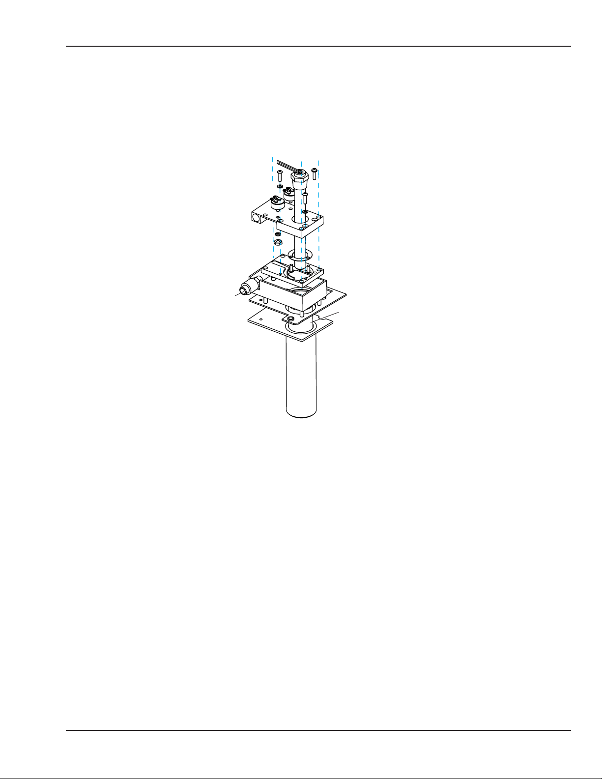
Chapter 1: Functional Description
1.9 Humidier
Refer to the following diagram. Water enters the insulating cylinder (1) through a small hole in bottom. Steam
rises along the heater cartridge protective insert (2) and is channeled between the heater mount (3) and the
ramp block (4) and out the steam port (5).
3
4
5
2
1
Figure 1-2 Humidier
© 2001 by Datex-Ohmeda, Inc.. All rights reserved. 6600-0343-000 104 9
Page 38

Chapter 1: Functional Description
10 6600-0343-000 104 © 2001 by Datex-Ohmeda, Inc.. All rights reserved.
Page 39
Chapter 2: Service Checkout
2.1 Setup
The OmniBed is shipped with the canopy in the locked down position. Before the canopy can be raised the rail
shipping locks must be released. They are located in both sides of the OmniBed near the outside bottom of the
uprights. An orange tear-away label marks their location. The lock consists of a socket head cap screw in a slot.
Tightening the screw disengages the screw head from the slot and releases the lift rail. Using the 4 mm hex
key provided with the unit, turn the screw clockwise about 8 rotations until the screw securely seats in its hole.
Remove the tear away label.
WARNING:
Do not perform the preoperative checkout procedure while the patient occupies the unit.
WARNING:
Complete the preoperative checkout procedure section of this manual before putting the unit into
operation. If the equipment fails any portion of the checkout procedure it must be removed from
use and repaired.
2.2 Mechanical Checks
1. Disconnect the power cord for the mechanical portion of the preoperative checkout procedure.
2. Examine the power cord for any signs of damage. Replace the cord if damage is evident.
3. Check that both plug retaining brackets are in place.
4. Examine the unit overall for any damaged or missing parts.
5. Check that all the casters are in rm contact with the oor and that the unit is stable. Lock the caster
brakes and check that they hold the unit in place. Release the brakes and check that the unit moves
smoothly.
6. Check the operation of the two side doors. Open the doors and check that they swing all the way down and
hang perpendicular to the bed. Check that the doors are securely attached to the unit and that the hinge
pins are properly seated. Check that the inner walls are securely fastened to the doors. Close the doors and
check that the latches hold the doors securely shut. The orange latch open indicators should not be visible
when the latches are engaged. Check that the top of the doors meet the canopy seal.
© 2001 by Datex-Ohmeda, Inc.. All rights reserved. 6600-0343-000 104 11
Page 40

Chapter 2: Service Checkout
7. Check the canopy seals:
a. If the unit has original canopy seals, which are attached with fasteners, check for visible cleanliness.
b. If the unit has enhanced canopy seals, which can be removed by hand, check the following:
• Check for visible cleanliness.
• Make sure that all seals (the two south corner covers, the two long side seals, the short south seal,
and the notched north seal) can be easily removed and reinstalled. For details, refer to section 5.2.1,
steps 10 and 15.
• Make sure that none of the red indicators are visible after reinstallation.
8. Check the portholes. Open the portholes by pressing on the latch. The cover should swing open. Close the
porthole and check that the latch holds the cover securely shut and that the cover seals tightly against the
porthole gasket. Check that all the porthole seals are in place and are in good condition.
9. Check that the tubing access covers in the four bed corners and the large slot grommet at the head of the
bed are in place and are in good condition.
10. Check the operation of the bed. The bed should rotate easily without binding. If the bed is properly seated
and locked in place, the mattress should be level. With the bed rotated back into the straight position,
check to see that the bed platform extends and stops when it is pulled out on either side. Check the
operation of the bed tilt mechanism. Squeeze the tilt control and push down on the foot of the bed. The
head of the bed should raise easily, and should stay in position at any angle along its tilt path when the tilt
control is released. Push down on the head of the bed. The foot of the bed should raise easily, and should
stay in position at any angle along its tilt path when the tilt control is released.
2.3 Controller Checks
WARNING:
Do not use the OmniBed in the presence of ammable anesthetics: an explosion hazard exists
under these conditions.
1. Connect the OmniBed power cord to a properly rated outlet.
2. Connect the patient probe to jack 1 on the probe panel.
3. Switch on the power at the mains switch on the back of the unit, and at the standby switch on the jack
panel, while holding in the override button (>37) on the control panel during power up until the software
revision screen appears. Release the button and the rst service screen will appear.
4. Scroll to “Down” and select it to bring up the second service screen. Select Status to see Status screen.
Check status of the software self tests. These include: incubator heater on (INCHTRON), warmer heater on
(WRMHTRON), incubator/warmer heater o (I/WHTROFF), humidier heater on (RHHTR), remote monitoring
data stream (RS232LOOP), incubator fan on (FANON), and incubator fan o (FANOFF). All test should say
PASS except RS232 LOOP (the connector pins must be shorted to get the PASS message).
12 6600-0343-000 104 © 2001 by Datex-Ohmeda, Inc.. All rights reserved.
Page 41

Chapter 2: Service Checkout
5. Using the standby switch turn o the unit, then turn it back on. Verify the following:
• All the displays and indicators light
• The software revision appears
• The prompt tone begins
NOTE: If the unit has been used in the last 2 hours, the patient history query appears.
6. Adjust the set temperature to silence the prompt tone.
7. Check the patient probe. If the probe is below 30 C, the display will show -L-. Warm it by placing it between
your ngers, and verify that the baby temperature reading increases.
8. Unplug the patient probe and check that both visual and audio alarms trigger in the Baby control mode.
9. Check the canopy lift mechanism. Push the lift pedal and verify the canopy raises smoothly in one
continuous movement to its upper limit, the heater doors open, and the unit shifts into warmer operation.
Check that the pedals on both sides of the unit raise the canopy.
10. With the canopy raised, check the operation of the panel at the foot of the bed. Check that after you lift
up on the panel, it swings down and hangs perpendicular to the bed. Check that the panel is securely
attached. Check that it swings back up and seats in the closed position.
11. Lower the canopy and verify that it stops when you remove your nger from the hand switch. Check that it
stops automatically at its lower limit, and that the canopy seal makes contact with all four bed sides, and
that the unit shifts into the incubator operating mode. Check that the raise and lower buttons at the head
of the bed on both sides of the unit raise and lower the canopy.
12. If so equipped, check the operation of the bed elevating system. Raise and lower the bed along its entire
travel range, checking that the mechanism operates smoothly. Check that the pedals on both sides of the
unit raise and lower the bed.
13. Check the power failure alarm and the battery backed up memory. Make note of the current control mode
and temperature settings and wait one minute, then unplug the OmniBed from the wall outlet. An alarm
should sound and the power failure indicator should light. Wait one to two minutes and plug the OmniBed
back in. Verify that the alarm cancels and that the OmniBed returns to the same control mode and
temperature settings it displayed before the power interruption.
NOTE: A fully charged battery should supply the power failure alarm for 10 minutes minimum (IEC 606012-19 clause 101.3). If the alarm is tested for the full 10 minutes, the OmniBed must be run at least two
hours to recharge the battery before it is used with a patient. Total recharge time is 10 hours. The battery
charges only when the unit is powered on.
14. Perform the Leakage Current and Ground Resistance checks in Chapter 3 of this manual.
© 2001 by Datex-Ohmeda, Inc.. All rights reserved. 6600-0343-000 104 13
Page 42

Chapter 2: Service Checkout
2.4 Humidity Check
Turn on the Girae unit and verify that the Servo Humidity icon is on the screen. Set the Humidity to 65%. Wait
for 4 minutes. If no alarms are seen (except for a possible “Add Water” message) the humidier is operational.
NOTE: It is not necessary to have water in the reservoir to perform this test.
2.5 Servo Controlled Oxygen Check
2.5.1 Leak Check
This test checks for leaks between the O2 sensors and the Heat sink vent tting.
1. Remove translation deck, tilt platform, upper pan, and fan.
2. Cover the heat sink vent near the fan shaft with adhesive tape. Make sure the tape will not interfere with
fan rotation. Reinstall the fan, upper pan, tilt platform, and translation deck.
NOTE: If the conical shaped rubber grommet was removed with the fan, when reinstalling fan be sure that
rubber grommet clicks into groove on fan shaft.
3. Power up the unit, hold down the ‘Air curtain’ button and press the ‘Down’ button to force the Girae into
low fan speed.
4. Set O2 set point to 21%; the display will show the actual concentration in the larger numerals next to the
set point. Open the doors until the actual concentration reaches 21% (ambient).
5. Run the Servo O2 calibration routine and wait for the calibration complete message. In approximately 20
seconds, the “Check O2 Supply” alarm should sound. If there is no alarm, the tubing between the sensor
housing and the heat sink vent tting has a leak or is disconnected. Repair the leak and repeat steps 1
through 4 of this procedure.
6. After performing the test, power o the unit. Remove the translation deck, tilt platform, upper pan, and the
fan, and remove the adhesive tape. Be sure to remove any residue on the heat sink left by the tape.
7. Reassemble the system and run the calibration routine one nal time.
2.5.2 Pre-use Checkout
This test checks for leaks between the chassis vent tting and the O2 sensors.
1. Connect an acceptable hose from an oxygen supply to the oxygen inlet tting on the unit. Supply pressure
should be between 310 kPa (45 PSI) and 586 kPa (85PSI).
2. Power up the unit.
14 6600-0343-000 104 © 2001 by Datex-Ohmeda, Inc.. All rights reserved.
Page 43

Chapter 2: Service Checkout
3. Set the Air Control set point to the desired temperature.
4. Wait for the air temperature to stabilize. This could take about 45 minutes, depending on your
circumstances.
5. Hold down the ‘Boost Air Curtain’ button and press the ‘Decrease Temperature’ button to force the unit into
low fan speed (Whisper Quiet Mode).
6. Wait 10 minutes to ensure stability of the Whisper Quiet Mode.
7. Select wrench icon on display screen to bring up setup menu. Select Cal Oxygen on the setup menu to
initiate calibration.
8. When calibration is completed, 100% oxygen is delivered for approximately 20 seconds to ensure there
are no occlusions in the system. Do not turn o the unit or disconnect the oxygen supply during this brief
period after the ‘Calibration Complete’ screen appears. Exit calibration screen.
9. Select O2 icon on display screen to bring up Servo Control Oxygen menu. Set O2 set point to 65%.
10. Start timer and verify that unit reaches 60% in less than 10 minutes.
NOTE: If rise time is longer than 10 minutes check all tubing between the O2 sensors and the chassis vent
tting. The chassis vent may be identied by its mushroom cap shaped cover.
NOTE: Unit should not be placed in service unless the calibration is successful and the rise time test passes.
NOTE: The Low O2 alarm may activate during the rise time test. Silence the alarm and let the test continue.
NOTE: The “O2 Cal Lost – No O2” alarm may appear after the unit is turned on or returned from power fail
condition. If this alarm appears, calibrate the oxygen sensors (using the wrench icon and the Cal Oxygen
option) and resume use. If this alarm appears during normal operation, calibrate and continue use, but call
service.
2.5.3 Supply Valve Leak Test
1. Connect oxygen supply to Servo Oxygen tting.
2. Disconnect the 10mm hose from the expansion chamber.
3. Power up unit in Service Mode.
4. The canopy should be closed for this step and step 5. Scroll to Servo Oxygen service screen, and open V1 &
V2 and verify that gas ows audibly .
5. Close V1 & V2 and place the 10mm hose in a cup of water. Verify that no more than 10 bubbles appear over
a one minute period. If unit fails, replace supply valves.
© 2001 by Datex-Ohmeda, Inc.. All rights reserved. 6600-0343-000 104 15
Page 44

Chapter 2: Service Checkout
6. Raise the canopy a couple of inches and open V1 & V2. Verify that no more than 10 bubbles appear over a
one minute period. If unit fails replace two-way valve or spring assembly.
When test is completed, reattach 10 mm hose to expansion chamber.
2.6 Scale Check
The scale can be calibrated or checked using a Class F calibration weight between 1 kilogram and 8 kilograms
(accuracy of 0.01%). (This class F Weight is available as part number 6600-0209-800.)
NOTE: For EU Member States:
• This scale has been designed and manufactured in accordance with the non-automatic weighing
instruments (NAWI) directive, 90/384/EEC. In order to assure complete compliance to the Directive, have
the unit calibrated by an accredited local test authority. If you are unable to identify a test authority, please
contact your GE representative or distributor for assistance.
• Periodic re-verication (calibration) of the scale must be performed in accordance of the National
Regulations Governing Legal Metrology. The required re-verication frequency will vary by country. Contact
your local weights and measures authority for more information.
2.6.1 Mechanical Check
1. Examine the scale connector cord for damage.
2. Examine the LEMO connector to make sure it is tightly assembled.
3. Check for bent pins.
4. Examine the scale for obvious signs of damage.
5. If any of the parts are damaged replace them.
2.6.2 Weight Checks
IMPORTANT: If the scale fails the weight checks, calibrate it according to the procedure in Chapter 3 and then
perform the weight checks again.
2.6.2.1 Center Weight Check
1. Enter the service screen by holding the override key (>37) while powering up. Set the scale resolution to 5
grams (if option is available).
2. Shut o the unit and power it back up to enter normal weighing mode.
3. Place a known weight in the center of the mattress and perform a weigh cycle. The displayed weight should
be the known weight +/- 10 grams.
16 6600-0343-000 104 © 2001 by Datex-Ohmeda, Inc.. All rights reserved.
Page 45

Chapter 2: Service Checkout
2.6.2.2 O Center Weight Check
1. Enter the service screen by holding the override key (>37) while powering up. Set the scale resolution to 5
grams (if option is available).
2. Shut o the unit and power it back up to enter normal weighing mode.
3. Place a known test weight 10 cm (4”) from the center of the mattress in 4 positions 90 degrees from each
other (for example- toward each corner of the mattress) and check the reading at each position. Resulting
weight readings should be within +/- 10 g of previously obtained center weight reading.
2.7 Other Accessory Checks
1. Check that all accessories are securely mounted and out of the path of the canopy.
2. Check the operation of any accessories with reference to their appropriate operation manuals.
3. Set up any required suction or gas supply systems. Check them for leaks as described in their respective
operation manuals.
© 2001 by Datex-Ohmeda, Inc.. All rights reserved. 6600-0343-000 104 17
Page 46

Chapter 2: Service Checkout
2.8 Cable Connections and Mechanical Controls
Numeric Temperature Displays
Temperature
Regulation
Controls
Tubing Grommets
Standby
Power
Switch
(I/O)
Drainage
Hanger
Caster
Brake
Graphics Screen
Control Knob
Canopy
Compartment Probes
Side Door Latch
Tubing Grommets
Humidier Reservoir
(air intake lter located
behind reservoir)
Probe Jacks
Accessory
Power Outlets
Ventilator
Slot
Side Door
Latch
RS 232
Connector
Controller
Cover
Mains Power
Switch
Plug retaining brackets
not shown for clarity
FRONT
O2 connection for
Servo Controlled Oxygen option
BACK
Power
Cord
Inlet
Figure 2-1 Connections and Controls
18 6600-0343-000 104 © 2001 by Datex-Ohmeda, Inc.. All rights reserved.
Page 47

Canopy
Chapter 2: Service Checkout
Control Panel
Portholes
Upright
Side Door Latch
Drainage
Hanger
Storage Drawer
Raise Canopy Pedal
SIDE
Dovetail rail
Canopy Raise/Lower Switches
Pleural Drainage Hanger
Elevating Column
Bed Height Pedal
© 2001 by Datex-Ohmeda, Inc.. All rights reserved. 6600-0343-000 104 19
Page 48

Chapter 2: Service Checkout
20 6600-0343-000 104 © 2001 by Datex-Ohmeda, Inc.. All rights reserved.
Page 49
Chapter 3: Calibration and Maintenance
SENSITIVE TO ELECTROSTATIC DISCHARGE CAUTION
An Electrostatic Discharge (ESD) Susceptibility symbol is displayed to alert service personnel that the
part(s) are sensitive to electrostatic discharge and that static control procedures must be used to
prevent damage to the equipment.
WARNING:
After performing any repair or calibration, always perform the Service Checkout Procedure before
putting the unit back into service.
3.1 Service Maintenance Schedule
The unit should be maintained in accordance with the procedures detailed in this manual. Service maintenance
must be performed by a technically competent individual.
This schedule lists the minimum frequencies. Always follow hospital and local regulations for required
frequencies.
Frequency Maintenance
• Perform the electrical safety and calibration procedure as described later in this chapter.
• If the unit is equipped with a scale, perform checkout procedures in Chapter 2. If the
scales fail the weight check, perform the scale calibration procedure in section 3.7.
• If the unit is equipped with Servo Controlled oxygen:
Annually
Every Two
Years
Every Three
Years
• Replace vent screen.
• Perform supply valve leak test.
• Replace sensors*. It is recommended both sensors be replaced at the same time.
*Sensor life of one year is approximate. If the sensor is used often at high oxygen concentrations, sensor life will
decrease.
• Replace the battery.
NOTE: The battery is used to sound the power failure alarm and to power memory circuits
during a power failure. Run the unit for at least two hours to charge the new battery before
using the unit. The battery charges only when the unit is powered on.
Calibrate the humidier.
© 2001 by Datex-Ohmeda, Inc.. All rights reserved. 6600-0343-000 104 21
Page 50
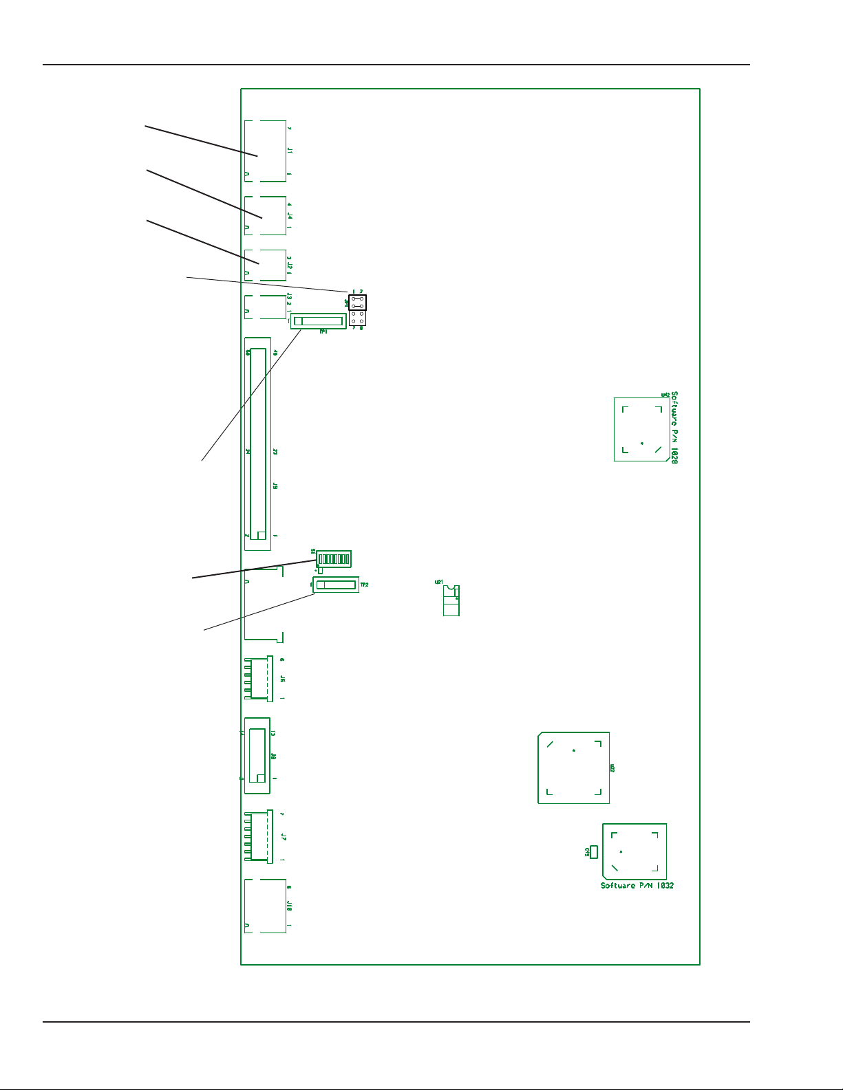
NORMAL
MODE
CAL
MODE
Chapter 3: Calibration and Maintenance
J1
J4
J2
Calibration jumper
Test Point 1
Dipswitch
Test Point 2
12345678
Figure 3-1 Control Board Test Points
22 6600-0343-000 104 © 2001 by Datex-Ohmeda, Inc.. All rights reserved.
Page 51

Chapter 3: Calibration and Maintenance
3.2 Special Tools
The following tools (or their functional equivalents) are required to complete the recommended service
procedures:
• Digital Multimeter, 4-1/2 digit
• Leakage Current Tester
• PLCC Extractor for removing socketed chips
• Static Control Work Station (recommended)
• Light gray touch-up paint (Munsell .16GY8.56-0.44 chroma)-18ml.........................................................6600-0714-200
• Servo Humidity Calibration Kit .................................................................................................................................. 6600-0048-850
• 5 kilogram (5000 gram) Class F test weight* ..................................................................................................... 6600-0209-800
*The scale can be calibrated using a Class F calibration weight between 1 kilogram and 8 kilograms (accuracy of 0.01%).
NOTE: Do not use simulator 6600-0876-700 for validation testing.
3.3 System Calibration
NOTE: If only performing line voltage calibration, follow instructions in next section, 3.4.
IMPORTANT: Be sure to perform System Calibration after replacing a control board.
1. Turn power o.
2. Remove electrical enclosure back panel.
3. Unplug the temperature sensors and from J1, J4 and J2 on the control board.
4. Move jumper JP1 to the CAL MODE position on the control board (refer to “Figure 3-1 Control Board Test
Points”). Be sure to orient the jumper correctly so pins 5-6 and 7-8 are shorted.
5. Turn power on. After running the power-up testing INITIALIZING will be displayed and dots will move across
the top of the screen.
6. After about 90 seconds CALIBRATION MODE, Enter “VREF”, and Enter “Mains” will be displayed.
7. Using a 4 ½ digit DVM (capable of measuring to 0.1 millivolt) measure VREF at TP1, pins 1 and 6 (pin 6 is
ground) on the control board. Measure to the nearest 0.1 millivolt. (Typical voltage reading will be 1.2350)
8. Dial in VREF using the control knob. Press the knob to enter the value.
9. Measure the Mains Voltage at the AC connectors at the bottom of the electronics enclosure cover.
© 2001 by Datex-Ohmeda, Inc.. All rights reserved. 6600-0343-000 104 23
Page 52

Chapter 3: Calibration and Maintenance
10. Dial in the Mains voltage using the control knob. Press the knob to enter the value.
11. After a few seconds the dots will stop moving across the screen and DONE will appear on the top right of
the display. Do not shut o the unit until the DONE message is displayed or the new calibration values will
not be stored.
If the message “Mains voltage calibration failed. Please enter the mains voltage again” appears this
indicates the dialed in line voltage is 20% dierent than the measured value (not the nominal value).
12. Power down the unit and move the calibrate jumper to the NORMAL MODE position. Be sure to orient the
jumper correctly so pins 1-2 and 3-4 are shorted.
System and line voltage calibration are complete.
13. Proceed to humidier calibration.
3.4 Line Voltage Calibration
IMPORTANT: Be sure to perform line voltage calibration after replacing a relay board.
1. Hold the override button (>37) while powering up the unit to enter the service screen.
2. On the second service screen select CAL LV.
3. Measure the line voltage at the AC connectors located at the bottom of the electrical enclosure.
4. On the CAL LV screen, dial in the mains voltage value that you measured and push the knob to enter it.
5. When calibration is completed, the screen will say Mains Voltage Calibration Complete.
If the message “Mains voltage calibration failed. Please enter the mains voltage again” appears this indicates
the dialed in line voltage is 20% dierent than the measured value (not the nominal value).
24 6600-0343-000 104 © 2001 by Datex-Ohmeda, Inc.. All rights reserved.
Page 53

Chapter 3: Calibration and Maintenance
3.5 Humidier Calibration
IMPORTANT: Be sure to re-calibrate the humidier whenever either the sensor or the control board is replaced.
IMPORTANT: In order for the water in the calibration bottle (6600-0048-850) to be completely saturated, most
of the salt should not be dissolved. There should be as little standing water above the salt line as possible to
minimize the response time. The salt in the calibration bottle may only be used for a period of one year after its
initial mix with water then the kit should be discarded.
1. Take the cap o the humidity calibration bottle and add one half cap full of sterile distilled water to the
bottle. Shake the bottle to thoroughly mix the salt and water solution. Place the smaller end of the elbow
over the bottle.
2. Slide the elbow over the humidity sensor (mounted on the back wall) until it stops. This creates a 75% RH
environment for the sensor.
3. Hold the override key while powering up to enter the service screen.
4. On the second service screen, select Cal RH. The screen will prompt “Push knob when RH reading is stable.”
Wait for 20 minutes or until the RH display stabilizes (does not change by more than 1% in 5 minutes).
5. Depress the control knob to complete the calibration. On software revision 1.3 and higher, you will have
the option to select STABLE, SET TO DEFAULT or EXIT. STABLE initiates calibration. SET TO DEFAULT resets
calibration values back to factory default settings. If you started calibration by mistake (without the
calibration bottle in place, for example) you would select SET TO DEFAULT and then calibrate the unit. If you
have entered the calibration routine by mistake, select EXIT to leave without initiating calibration.
6. If “RH Sensor Calibration Completed” is displayed, the calibration is complete. Depress the knob to exit the
Cal RH routine.
7. If “RH Sensor Calibration Failed Try Again” is displayed, verify your setup and press the knob to try the
calibration again. This message appears if the signal from the RH sensor is outside the values expected
from the sensor at 65-85% RH. If the failure persists it means the readings are out of this range and either
the calibration bottle or the RH sensor may be defective.
© 2001 by Datex-Ohmeda, Inc.. All rights reserved. 6600-0343-000 104 25
Page 54
Chapter 3: Calibration and Maintenance
3.6 Servo Controlled Oxygen Calibration
1. Select Set Up icon (wrench) to bring up Set Up screen.
2. Scroll down and select Cal Oxygen to initiate calibration. Calibration is automatic and takes less than
ve minutes. A bar graph indicates progress toward completing calibration. If for any reason you wish to
discontinue calibration before it is completed, turning the control knob in either direction will cause the
word Cancel to appear on the calibration screen. Pushing in the control knob will discontinue calibration.
When calibration is completed, 100% oxygen is delivered for approximately 20 seconds to ensure there are no
occlusions in the system. Do not turn o the unit or disconnect the oxygen supply during this brief period after
the ‘Calibration Complete’ screen appears.
NOTE: The servo control oxygen system prompts for calibration every 24 hours, but the system may prompt for
calibration if there is a large leak in the system (for example if a door is open) for half an hour.
CAUTION:
The servo-control system must be calibrated at the same atmospheric pressure in which it is to be
used. Operation at atmospheric pressures other than that present during calibration may result in
readings outside the stated accuracy for the unit.
3.7 Scale Calibration
NOTE: For EU Member States:
• This scale has been designed and manufactured in accordance with the non-automatic weighing
instruments (NAWI) directive, 90/384/EEC. In order to assure complete compliance to the Directive, have
the unit calibrated by an accredited local test authority. If you are unable to identify a test authority, please
contact your GE representative or distributor for assistance.
• Periodic re-verication (calibration) of the scale must be performed in accordance of the National
Regulations Governing Legal Metrology. The required re-verication frequency will vary by country. Contact
your local weights and measures authority for more information.
NOTE: The scale is calibrated using a Class F calibration weight between 1 kilogram and 8 kilograms (accuracy
of 0.01%).
1. Place the test weight on the center of the bed.
2. Hold the override key while powering up to enter the service screen.
3. On the second service screen, select Cal Scale.
4. Remove the weight and push the knob at the screen prompt “REMOVE THE WEIGHT AND PUSH KNOB”. The
screen will prompt “INITIALIZING” for a few seconds.
26 6600-0343-000 104 © 2001 by Datex-Ohmeda, Inc.. All rights reserved.
Page 55

Chapter 3: Calibration and Maintenance
5. Replace the weight and push the knob at the screen prompt “PLACE TEST WEIGHT AND PUSH KNOB”. The
screen will prompt “MEASURING” for a few seconds.
6. When the screen prompts “ENTER TEST WEIGHT” Dial in the test weight to the nearest gram. Press the knob
to enter. The screen will prompt “CALCULATING” for a few seconds.
7. When the screen prompts:
SAVE AND EXIT
EXIT ONLY
RESTORE DEFAULT
Select and enter “SAVE AND EXIT”
8. Turn o the power to exit the service mode.
3.8 Leakage Current
Use approved equipment and techniques to test the unit’s leakage current and ground continuity. Follow the
directions supplied by the test equipment manufacturer to verify the following:
1. Less than 300 microamperes measured at any exposed metal surface for equipment rated at 120 Vac,
50/60 Hz.
2. Less than 500 microamperes measured at any exposed metal surface for equipment rated at 220 Vac,
50/60 Hz or 240 Vac, 50/60 Hz.
3.9 Ground Resistance Check
Measure the resistance between the ground pin on the line cord plug and exposed metal of the electronic
enclosure. The ground resistance must be less than 0.2 ohms.
© 2001 by Datex-Ohmeda, Inc.. All rights reserved. 6600-0343-000 104 27
Page 56

Chapter 3: Calibration and Maintenance
28 6600-0343-000 104 © 2001 by Datex-Ohmeda, Inc.. All rights reserved.
Page 57

Chapter 4: Troubleshooting
4.1 Startup Sequence
By default, the Girae OmniBed starts up in user mode. The next section describes how to start up the
OmniBed in service mode. The following table describes the Girae OmniBed startup sequence for each mode:
User Mode Service Mode
1. The alarm light turns on and remains on.
1. The alarm light turns on and remains on.
2. All LEDs and segments light up and the EL screen
is yellow.
3. All LEDs turn o. The EL screen displays the
Girae logo.
4. The alarm light turns o. Software revisions
appear on the EL screen with OKs.
5. The user screen appears.
2. All LEDs and segments light up and the EL screen
is yellow.
3. All LEDs turn o. The EL screen displays the
Girae logo.
4. The alarm light turns o. Software revisions
appear on the EL screen without OKs.
5. The service screen appears.
© 2001 by Datex-Ohmeda, Inc.. All rights reserved. 6600-0343-000 104 29
Page 58

Chapter 4: Troubleshooting
4.2 Service Screen
To access the service screen, hold in the override button (>37) during power up until the software revision
screen appears. Release the button and the rst service screen will appear.
Figure 4-1 First Service Screen
Default options that may be selected from this screen appear along the left side of the screen
Digital/Analog Converter voltage. This is the over temperature voltage that is used by the system to verify
DAC Volt
Language
Temp U
Volume Select one of four volume settings. 1 is minimum, 4 is maximum.
Pat Alarm
Elevate
Pat Ctrl Allows you to disable patient control.
Pat Algo To be used for future software options.
Preheat
Canopy
Scale U
the computer independent circuitry is working. To manually test this circuit enter voltages from 0 to .5 V.
The DV value at the bottom right corner of the screen should match this value within 10mV.
English is the default language that appears on the EL display, but you can select French, Spanish, etc.,
depending on what software is installed.
Changes temperature displays to show “Fahrenheit”, “Celsius” or “Celsius Only” so the Fahrenheit option
is not present on the user Set-up screen (Celsius is factory set default).
Set the default Hot Baby/Cold Baby alarm to activate when either 0.5ºC or 1.0ºC dierence is read
between a set temperature and the baby probe temperature.
Disable or enable the bed up/down pedal switches. If the pedals are disabled on the service screen, they
cannot be enabled on the user setup screen (wrench icon).
Select from 10 to 50% radiant heater power to preheat without alarms; 25% is the default.
NOTE: Resetting maximum preheat level to above 25% will result in noncompliance to device standard
IEC 60601-2-21
Disable or enable the canopy pedal switches; hand switches will remain active. If the switches are
disabled on the service screen, they cannot be enabled on the user setup screen (wrench icon).
Select from “Grams”, “Pounds” or “Grams Only” so that the pounds option is not present on the user Scale
screen (grams is the factory default).
30 6600-0343-000 104 © 2001 by Datex-Ohmeda, Inc.. All rights reserved.
Page 59

Chapter 4: Troubleshooting
Scale R Select from 2 scale resolution settings; 10 grams or 5 grams (10 grams is the factory default).
Comfort Allows you to remove the Comfort Screen feature.
Set Time
View Mods
Down Go to second service screen.
Up Return to previous screen.
Status
Set real time clock for time, day and date. Choose how date is displayed (North American or European).
Choose a 12 hour (AM/PM) or 24 hour time display.
Display the current software revision of the options installed on this specic unit (Humidier, Scale, SPO2,
etc.)
Figure 4-2 Second Service Screen
Check status of all self test the software
runs continuously. These include: incubator
heater on (INCHTRON), warmer heater on
(WRMHTRON), incubator/warmer heater
o (I/WHTROFF), humidier heater on
(RHHTR), remote monitoring data stream
(RS232LOOP), incubator fan on (FANON), and
incubator fan o (FANOFF).
Switches
If the RS232 option is not installed
RS232LOOP will display N/A. To test the
circuit if the option is installed, short pins 2
and 3 on the 9 pin connector on the back of
the electrical enclosure.
Select to bring up a diagnostic diagram of the unit that displays the status of all the switches. If the circle
next to the switch is lit, the switch is closed; if it is not lit, the switch is open. Also, while the switch status
screen is active, you can hold down the alarm silence button to light the alarm light, system failure light
and all LED segments to test them.
Figure 4-3 Status Menu
© 2001 by Datex-Ohmeda, Inc.. All rights reserved. 6600-0343-000 104 31
Page 60

Heater doors open
Chapter 4: Troubleshooting
Canopy up
Canopy middle
Heater doors closed
Override control
Baby mode control
Increase control
Canopy hand
switch up
Canopy hand
Manual mode control
Decrease control
switch down
Air mode control
Canopy down
Bed down
pedal
Bed up pedal
Canopy pedal
Boost air curtain
control
Humidier
add water
Humidier reservoir
engaged
Figure 4-4 Switch Diagnostic Diagram
Errors
Lists a chronological log of the last 8 system errors that occurred. Shows error number and date. It is
possible to clear the list.
Brings up a screen with 2 hour meters; one that is resetable and one that is not. To reset the resetable
Hours Run
hour meter, highlight CLEAR and push the control knob. The non-resetable hour meter will roll to 0 at
199,999.
Cal LV Use to calibrate line voltage at the factory. To calibrate line voltage follow the procedure in section 3.4.
Use to enable or disable the patient temperature alarms in the manual mode (revision 1.40 and higher
Man temp al.
software only). If disabled on the service screen, it cannot be enabled on the user setup screen (wrench
icon). The alarm will not activate if a patient set point has not been entered.
Figure 4-5 Pedal Screen
Pedals
BatLoad Used for manufacturing only, not for service use.
Cal RH
Cal Scale
32 6600-0343-000 104 © 2001 by Datex-Ohmeda, Inc.. All rights reserved.
In the event of a bed up/down or canopy pedal switch failure, selecting pedals allows the canopy to be
raised or the bed to be raised or lowered (revision 1.6 software and higher).
Brings up humidier calibration screen. Refer to “Chapter 3: Calibration and Maintenance” for information
on how this screen is used.
Brings up scale calibration screen. Refer to “Chapter 3: Calibration and Maintenance” for information on
how this screen is used.
Page 61

Chapter 4: Troubleshooting
A number of diagnostic readings appear on the right side of the service screens.
Figure 4-6 Service Screen
HFS High fan speed. Should be 1500 +/- 100 (measured at power up only).
LFS Low fan speed. Should be 1000 +/- 100 (measured at power up only).
RH Relative Humidity. % humidity read in the patient chamber.
SR Scale counts raw.
SC Scale counts corrected. (1 count = 1 gram)
ADT
ACT
Air display temperature. Temperature read by the rst thermistor in the compartment air
probe. Should be + 0.3ºC of ACT temperature.
Temperature read by second thermistor in the compartment air probe. Should be + 0.3ºC of
ADT temperature.
P11 Reading from the rst thermistor in patient jack 1. Should be +/- 0.5ºC of P12 temperature.
P12 Reading from the second thermistor in patient jack 1. Should be +/- 0.5ºC of P11 temperature.
P21 Reading from the rst thermistor in patient jack 2. Should be +/- 0.5ºC of P22 temperature.
P22 Reading from the second thermistor in patient jack 2. Should be +/- 0.5ºC of P21 temperature.
HSP
Heat sink sensor resistance. Should be 20000 ohms @ 25ºC. Refer to the Tips section (4.6.8) for
resistance verses temperature values.
LV1 Line voltage in rst mains circuit. Should be +/- 4V of LV2.
LV2 Line voltage in second mains circuit. Should be +/- 4V of LV1.
LF 60Hz or 50Hz.
MC Motor current. Shows current drawn by the canopy or e-base motor.
TV Thermistor voltage. Voltage of thermistor circuits located on the mother board.
5V Power supply voltage. Should be + 0.25V of 5V.
VR Voltage reference. Independent voltage reference. Should be 1.235V + 1%.
DV DAC output voltage. It should match the DAC volt value within 10 mV.
BV Used for manufacturing only, not for service use.
Across the bottom of the screen the date of last time the temperature and line voltage calibration was
performed appears plus the current time settings of the unit.
© 2001 by Datex-Ohmeda, Inc.. All rights reserved. 6600-0343-000 104 33
Page 62

Chapter 4: Troubleshooting
4.3 Alarm Messages
This section describes the alarm messages that may appear for the Girae OmniBed. The alarms have been
organized in this section alphabetically.
4.3.1 “Air Probe Failure” Alarm
Cause or Circumstances Failure Action
Measure the resistance of the two sensors at the
harness from control board J1, Pins 1-2, and 3-4. Under
stable conditions, the resistances should be within
The software detected a
dierence in the two air
thermistors of > 0.5ºC
Defective control board.
Defective compartment air
probe or harness
about 100 ohms. If defective, disassemble the air probe
assembly and disconnect the 5 pin connector inside.
Measure resistance of the two thermistors at pins
1-2 and 3-4 to determine if the sensor or harness is
defective. Refer to the Tips section (4.6.7) for resistance
values.
If the thermistors and harness measure OK, replace the
control board.
4.3.2 “Air Temp >38C” or “Air Temp >40C” Alarm
Cause or Circumstances Failure Action
Air Temp >38C or Air Temp
>40C alarm activated even
though compartment temp is
< alarm temp.
This alarm does not self
reset after alarm condition is
resolved.
None Push the alarm silence button to clear the alarm.
4.3.3 “Baby Hot” or “Baby Cold” Alarm
Cause or Circumstances Failure Action
Baby Hot or Baby Cold alarm
activated while unit is in
Manual or Air mode.
None
MANUAL TEMP alarm is set
as active on the nurse setup
screen or the service screen.
On service screen or nurse setup screen, select OFF for
the MAN TEMP ALARM setting.
34 6600-0343-000 104 © 2001 by Datex-Ohmeda, Inc.. All rights reserved.
Page 63

4.3.4 “Baby Mode Disabled” Alarm
Cause or Circumstances Failure Action
Baby mode has been disabled
in the service screen and
baby mode button is pressed.
None
Press alarm silence button to deactivate the alarm.
If you wish to use the baby mode, re-enable it in service
screen.
4.3.5 “Baby Probe 1 Failure” or “Baby Probe 2 Failure” Alarm
Cause or Circumstances Failure Action
Defective patient probe Replace patient skin probe.
Plug patient probe into probe jack 1. In service mode,
Probe thermistors show
dierence > 0.5ºC.
Defective patient probe jack
wiring
note the dierence between readings from P11 and
P12. Plug the same probe into probe jack 2 and note the
dierence between readings from P21 and P22. If they
are greater there is resistance in the probe jack harness.
Replace the harness.
Chapter 4: Troubleshooting
4.3.6 “Bad Membrane Switch” Alarm
Cause or Circumstances Failure Action
All
Defective membrane switch
panel
Test switches in service mode. Replace membrane
switch panel.
© 2001 by Datex-Ohmeda, Inc.. All rights reserved. 6600-0343-000 104 35
Page 64

Chapter 4: Troubleshooting
4.3.7 “Bed Heater Failure” Alarm
This alarm activates only when the canopy is at the bottom position.
Cause or Circumstances Failure Action
The software has turned on
the incubator heater but it is
either not turning on or the
current sense circuit is not
detecting that it is on.
The bed safety thermostat is
open (possibly because the
unit was shut down when the
heater was hot).
Defective incubator heater,
thermostat, or wire harness.
Defective incubator solid
state relay (SSR).
Defective 50 pin ribbon cable
between the relay and control
board.
Defective relay board. Replace the relay board.
If the unit was shut o when the heater was hot, allow
the fan to run for several minutes to cool to below 40
degrees C then power down and back up. If the failure
still persists, continue .
Check the resistance of the incubator heater. Refer
to the Tips section (4.6.2). If defective, remove the
chassis cover and measure resistance at thermostat
and heaters to determine if heater, thermostat, or wire
harness is defective.
In service mode, check the voltage across the control
line of the incubator heater SSR. This control signal
varies between 0 VDC and about 12 VDC.
If voltage is present replace SSR. The two SSRs are
identical and can be swapped for troubleshooting. If no
voltage, continue.
Check for continuity on pins 36, 38, 39, and 40 (control
signals). If defective, replace cable. If OK, continue.
4.3.8 “Bed Up/Down Pedal Failure” Alarm
Cause or Circumstances Failure Action
Check the switches on the service screen to determine
One of the bed up/down
pedal switches is shorted.
Defective relay board. Defective relay board. If the alarm persists, replace the relay board.
Defective bed up/down pedal
switch or harness.
which switch is shorted or open. Refer to the Tips
section (4.6.9). Raise the lower shroud and check
continuity at the switch connectors to determine if a
switch is defective or the wiring has a short.
4.3.9 “Bed Up/Down Pedal Switches Disabled” Alarm
Cause or Circumstances Failure Action
Bed up/down pedal switches
have been disabled in nurse
setup screen or service
screen and pedal is pressed.
None
When pedal is released, the alarm deactivates.
NOTE: If the bed up/down pedal switches are disabled
in the service screen and you wish to use them, you can
reactivate them only in the service screen.
36 6600-0343-000 104 © 2001 by Datex-Ohmeda, Inc.. All rights reserved.
Page 65

4.3.10 “Canopy Pedal Disabled” Alarm
Cause or Circumstances Failure Action
Canopy pedal switches have
been disabled in nurse setup
screen or service screen and
pedal is pressed.
None
When pedal is released, the alarm deactivates.
NOTE: If the canopy pedal switches are disabled in
the service screen and you wish to use them, you can
reactivate them only in the service screen.
4.3.11 “Canopy Pedal Failure” Alarm
Cause or Circumstances Failure Action
One of the canopy pedal
switches is shorted. (The
alarm appears about 100
seconds after the short.)
One of the canopy hand
switches is shorted.
Defective canopy pedal
switch or harness.
Defective canopy hand switch
or harness.
Check the switches on the service screen to determine
which is shorted. Refer to the Tips section (4.6.9). Raise
the lower shroud and check continuity at the switch
connectors to determine if a switch is defective or the
wiring has a short.
Replace one switch. If the error persists, replace the
other switch.
Chapter 4: Troubleshooting
4.3.12 “Canopy Pedal Pressed” Alarm
Cause or Circumstances Failure Action
When the canopy pedal switch is released, the alarm
deactivates. If alarm silence button is pressed or the
The canopy pedal switch was
pressed and held on during
power up.
Other
None
Canopy pedal switch has
failed
pedal remains on for 100 seconds the Canopy Pedal
Failure alarm activates and the canopy pedal switches
are disabled. You can still raise and lower the canopy
using the hand switches. Shut down the unit and power
up to clear failure.
Refer to section 4.3.11 for troubleshooting information.
4.3.13 “Down Pedal Pressed” Alarm
Cause or Circumstances Failure Action
When the bed down pedal switch is released, the
The bed down pedal switch
was pressed and held on
during power up.
Other
None
Bed down pedal switch has
failed
alarm deactivates. If alarm silence button is pressed or
the pedal remains on for 100 seconds the Bed Down
Pedal Failure alarm activates and the bed down pedal
switches are disabled. Shut down the unit and power up
to clear failure.
Refer to section 4.3.8 for troubleshooting information.
© 2001 by Datex-Ohmeda, Inc.. All rights reserved. 6600-0343-000 104 37
Page 66
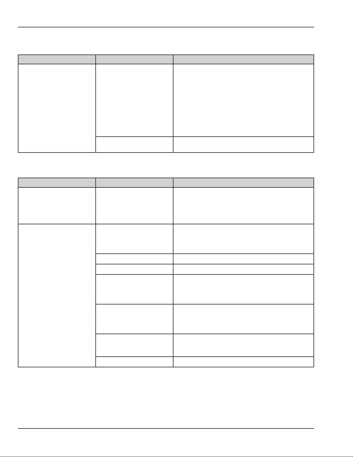
Chapter 4: Troubleshooting
4.3.14 “Fan Always in High Speed” Alarm
Cause or Circumstances Failure Action
Check the heat sink temperature sensor resistance
in service mode. You can also check heat sink sensor
resistance by disconnecting the harness from J3 at the
control board. Measure between pins 1 and 2. Refer to
Software cannot read
temperature of the heat sink
sensor in incubator heat sink.
Defective heat sink sensor or
harness.
Defective control board.
the Tips section (4.6.8).
If defective, remove the chassis cover and disconnect
the harness from heat sink sensor. Measure sensor
resistance at pins 1-2 on the sensor harness to
determine if sensor or harness is defective.
If the heat sink sensor and harness measure OK, then
replace the control board.
4.3.15 “Fan Failure” Alarm
Cause or Circumstances Failure Action
NOTE: System failure 25 and FAN FAILURE are both
Fan rotation is not being
detected.
Optical fan sensor not
detecting the fan
Fan or fan hub not seated
properly
Defective fan motor Replace the fan motor.
triggered by the optical fan sensor not detecting
the fan. If this occurs at power-up, a system failure
25 will activate. If it occurs after the power tests are
completed, the FAN FAILURE alarm will activate.
Verify the fan hub is properly seated all the way down
on the fan shaft. (It may be necessary to wet the part
to get it to slide all the way down on to the shaft.) Verify
the fan is seated in the groove at the top of the hub.
Defective relay board Replace the relay board.
Replace with new design fan. The new fan can be
Old design fan.
Fan is not turning.
Defective or obstructed
optical sensor. Sensor holder
or sensor gasket dirty or
crazed.
Defective 50 pin ribbon cable
between the relay and control
board.
Defective relay board. If the problem persists, replace the relay board.
38 6600-0343-000 104 © 2001 by Datex-Ohmeda, Inc.. All rights reserved.
identied by the grooves molded in the 2 black areas on
the bottom of the fan (side facing the heat sink). The old
fan has smooth surfaced black areas.
Check that sensor, sensor holder, and gasket and free
of dirt or other contaminants. Clean or replace.
Check for continuity on pin 9 (AIRFLOW). If defective,
replace the cable. (Refer to the Tips section, 4.6.11.)
Page 67
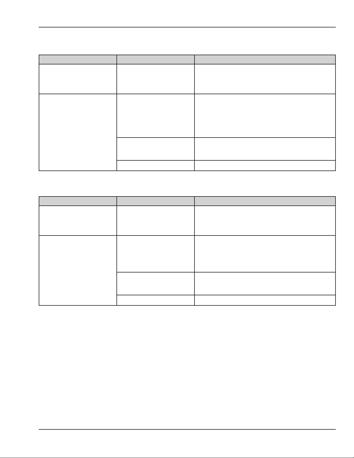
4.3.16 “Heater Doors Not Closed” Alarm
Cause or Circumstances Failure Action
This alarm activates as
the canopy reaches about
halfway down and the heater
doors are not both closed.
Doors are closed.
Doors not closing.
Defective switch or harness.
Defective 50 pin ribbon cable
between the relay and control
board.
Defective relay board. Replace the relay board.
Check to sure both heater doors are closing fully as the
canopy starts to lower. If not, x mechanical problem.
The two heater door switches are in series. Check
for continuity at J31 1-3. If defective, remove heater
housing cover and check continuity at connector
in switch harness pins 1-3 to determine if switches
or harness in rail is defective. If continuity is good,
continue.
Check for continuity on pin 8. If defective, replace the
cable. If good, continue.
4.3.17 “Heater Doors Not Opened” Alarm
Chapter 4: Troubleshooting
Cause or Circumstances Failure Action
This alarm activates as the
canopy reaches the top of its
travel and the heater doors
are not both open.
Doors are open
Doors not opening
Defective switch or harness
Defective 50 pin ribbon cable
between the relay and control
board.
Defective relay board Replace the relay board.
Check to be sure both heater doors are opening fully
when the canopy is all the way up. If not, x mechanical
problem. For example, adjust the spring tube position to
allow full travel.
The 2 door switches are in series. Check for continuity
at J31 2-3. If defective, remove heater housing cover
and check continuity at connector in switch harness
pins 2-3 to determine if switches or harness in rail is
defective. If continuity is good, continue.
Check for continuity on pin 7. If defective, replace the
cable. If good, continue.
© 2001 by Datex-Ohmeda, Inc.. All rights reserved. 6600-0343-000 104 39
Page 68
Chapter 4: Troubleshooting
4.3.18 “Humidier Failure” Alarm
NOTE: The “Humidier Failure” alarm can be caused by non-humidier issues.
Cause or Circumstances Failure Action
The Motor Drive Failure alarm
is on.
The Elevating base does not
function. If the elevating base
does not function, then safety
relay 2 is not being energized.
Elevating base functions
Humidier heater measures
OK
No mains voltage at input
to humidier isolation
transformer. (J55, 1-2)
If this alarm activates, it
opens safety relay 2 and
disables the humidier.
Defective 50 pin ribbon cable
between the relay and control
board.
Humidier safety thermostat
is open.
Defective humidier heater or
humidier safety thermostat.
Relay boards rev 10 or higher
Relay boards rev 9 or lower.
Humidier Interface Board is
mounted on relay board
Defective fuse. Relay boards
rev 10 or higher
Defective fuse. Relay boards
rev 9 or lower. Humidier
Interface Board is mounted
on relay board.
Defective relay board. Replace the relay board.
Refer to section 4.3.20 for troubleshooting.
Check for continuity on pin 34 (safety relay 2 control
signal). If defective, replace the cable. If good, replace
the relay board.
Wait for the heater to cool. Cycle power to see if alarm
resets.
Check safety thermostat and humidier heater
resistance. Refer to the Tips section (4.6.6).
In service mode, verify mains voltage is present at the
input to the humidier isolation transformer. (J55 1-2)
In service mode, verify mains voltage is present at the
input to the humidier isolation transformer. (J56 1-2)
J56 is on Humidier Interface Board mounted on relay
board.
Check fuses F3 and F4 on the relay board. If OK,
continue.
Check fuses on humidier interface board.
40 6600-0343-000 104 © 2001 by Datex-Ohmeda, Inc.. All rights reserved.
Page 69

4.3.19 “In Transition - Heat O” Alarm
Cause or Circumstances Failure Action
As the canopy reaches the
top position (for warmer
mode) or the bottom position
(for incubator mode), the
software does not see the
corresponding switch in the
right rail close, to signal that
the rail is at the end position.
WARMER MODE
The In transition Heat O
message does not go o
when canopy is all the way
up.
INCUBATOR MODE
In transition Heat O
message does not go o
when canopy is all the way
down.
NA
If the alarm message Heater
Doors Not Open is also
displayed, troubleshoot that
alarm rst.
Defective rail drive belt Check the belt. Refer to the Tips section (4.6.10).
Canopy is not going high
enough because spring tube
in right rail is not adjusted
correctly.
Defective switch or harness.
Canopy is not going low
enough because it needs
adjustment.
Defective switch or harness.
NOTE: This message should always be on when the
unit is in transition between the incubator and warmer
modes.
Try pushing up slightly on the canopy to see if the
switch closes and the message goes o. If it does,
adjust the spring tube position so there is less spring
tension. Refer to repair procedures, section 5.4.2 steps
14-15.
Switches can be tested in service mode. To check with
an ohmmeter, disconnect harness from J36 on relay
board. Measure resistance at pins 1-2. Should be open
and then close when canopy reaches top of its travel.
If not, either switch or harness are defective. Both are
located in right rail.
Adjust the canopy as described in Chapter 5.
Switches can be tested in service mode. To check with
an ohmmeter, disconnect harness from J36 on relay
board. Measure resistance at pins 1-2. Should be open
and then close when canopy reaches top of its travel.
If not, either switch or harness are defective. Both are
located in right rail.
Chapter 4: Troubleshooting
4.3.20 “Motor Drive Failure” Alarm
Cause or Circumstances Failure Action
The software has detected
that the elevating base motor
or the canopy motor was
running when not turned on.
© 2001 by Datex-Ohmeda, Inc.. All rights reserved. 6600-0343-000 104 41
Defective relay board.
Replace the relay board.
NOTE: Humidier will not operate during this failure.
Page 70
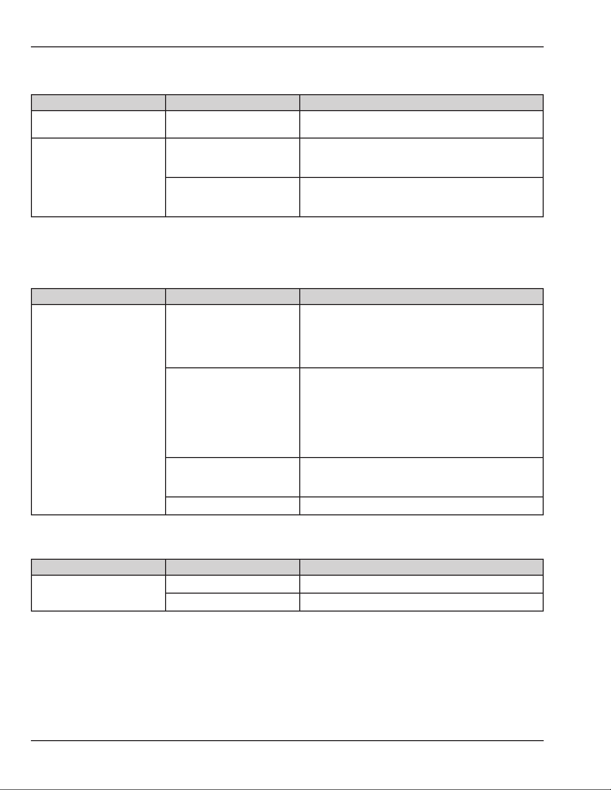
Chapter 4: Troubleshooting
4.3.21 Power Failure (LED Indicator)
Cause or Circumstances Failure Action
No AC power into unit
Mains power is present but
the 5V power supply is not
present.
On/O switch is not turned
on.
Defective fuse F1 or F2 on
relay board.
Defective power supply.
Verify cord is plugged into a live wall outlet. Verify power
switch/circuit breaker on back of unit is turned on.
Check the 5 volt supply. Refer to the Tips section (4.6.4).
If no 5 volts, possible defective fuses on mains to the
power supply, check F1 and F2 on relay board.
Check input to power supply for mains voltage. If
present and no 5 volts at output, then power supply is
defective.
4.3.22 “Radiant Heater Failure” Alarm
This alarm activates only when the canopy is at the top position.
Cause or Circumstances Failure Action
Check the resistance of the radiant heater. Refer to the
Tips section (4.6.3). If defective, remove heater housing
cover and measure resistance at 3 pin connector
on heater to determine if heater or wire harness is
defective.
In service mode, check the voltage across the control
line of the radiant heater SSR. This control signal varies
between 0 VDC and about 12 VDC.
If voltage is present, replace SSR. The two SSRs are
identical and can be swapped for troubleshooting. If no
voltage, continue.
Check for continuity on pins 37, 38, 39, and 40 (control
signals). If defective, replace cable. If OK, continue.
The software has turned on
the radiant heater but it is
either not turning on or the
current sense circuit is not
detecting that it is on.
Defective radiant heater or
wire harness.
Defective warmer solid state
relay (SSR).
Defective 50 pin ribbon cable
between the relay and control
board.
Defective relay board. Replace the relay board.
4.3.23 “Temperature out of Calibration” Alarm
Cause or Circumstances Failure Action
Calibration data is lost.
42 6600-0343-000 104 © 2001 by Datex-Ohmeda, Inc.. All rights reserved.
Defective calibration. Perform system calibration.
Defective control board. If problem persists replace the control board.
Page 71
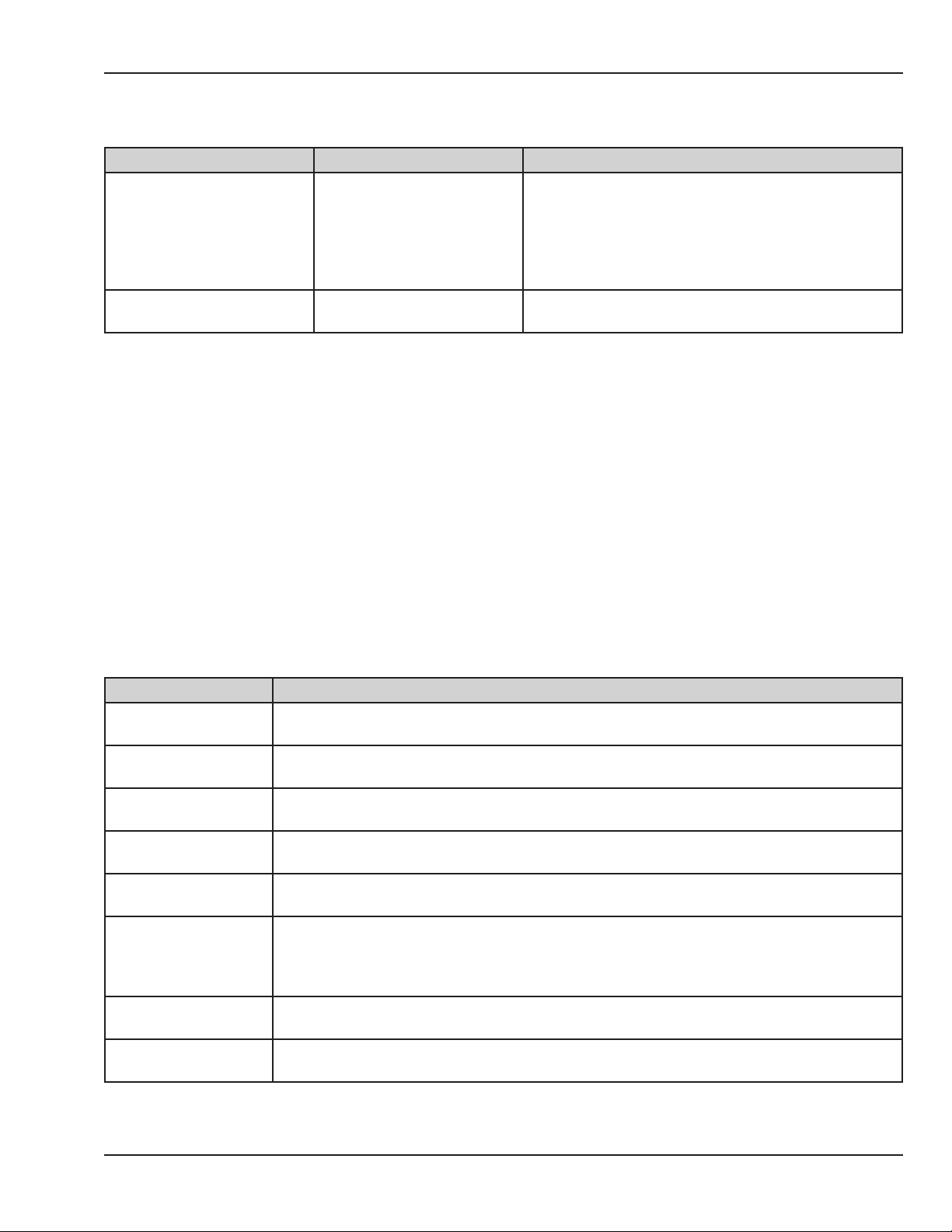
Chapter 4: Troubleshooting
4.3.24 “Up Pedal Pressed” Alarm
Cause or Circumstances Failure Action
When the bed up pedal switch is released, the alarm
The bed up pedal switch was
pressed and held on during
power up.
Other
None
Bed up pedal switch has
failed.
deactivates. If the alarm silence button is pressed or the
pedal remains on for 100 seconds, the Bed Up Pedal
Failure alarm activates and the Bed Up Pedal Switches
are disabled. Shut down the unit and power up to clear
failure.
Refer to section 4.3.8 for troubleshooting information.
4.4 Error Codes
The following sections describe the meaning of each system failure code for the Girae OmniBed. Each table
lists the possible causes and the corresponding recommended actions, in the order in which they should be
tried.
For information on Girae Scale error codes, refer to the Girae Scale Service Manual, which can be ordered as
part of a Girae OmniBed service manual kit: (US) 6600-0834-801 or (INTL) 6600-0834-802.
4.4.1 System Failure 0
System failure 0 indicates: Communication error between the display driver board and the control board.
Cause(s) Action(s)
Defective scale.
Defective scale
harness.
Defective Servo Oxygen
board.
Defective Servo Oxygen
cable.
Defective battery.
Defective 14 pin ribbon
cable between control
board and display
driver board.
Defective display driver
board.
Defective control
board.
Disconnect the scale connector at probe panel. Power cycle the unit. If the error clears,
replace the scale.
Disconnect the scale harness from J7 on the control board. (The scale may be plugged in.)
Power cycle the unit. If the error clears, replace the scale harness.
Disconnect the RS485 harness from J8 on the Servo Oxygen board. Power cycle the unit. If the
error clears, replace the Servo Oxygen Board.
Disconnect RS485 bus cable from J6 on the control board. Power cycle the unit. If the error
clears, replace the RS485 cable going to the Servo Oxygen board.
The battery is used only for power failure. Try powering up the unit with the battery
disconnected. If the error clears, replace the battery.
Check that the 14 pin ribbon cable is properly seated at J6 on the control board and at J20 on
the display driver board. (Have all three parts on hand and try them one at a time. Try routing
the cable around the outside of unit rst, then try the display board, and then try the control
board. If the error is intermittent, replace all three.)
Replace display driver board.
Replace control board.
© 2001 by Datex-Ohmeda, Inc.. All rights reserved. 6600-0343-000 104 43
Page 72

Chapter 4: Troubleshooting
4.4.2 System Failure 1
System failure 1 indicates: No Timer2.
Cause(s) Action(s)
The Timer2 circuit of the microprocessor on the control board is defective. Replace the control board.
4.4.3 System Failure 2
System failure 2 indicates: Timer2 too fast.
Cause(s) Action(s)
Defective scale.
Defective scale harness.
There is no line frequency signal to feed timer0 and
timer1 of the microprocessor on the control board, or
the timer2 of the microprocessor on the control board,
is defective.
Disconnect scale connector at probe panel. Power cycle the
unit. If the error clears, replace the scale.
Disconnect scale harness from J7 on the control board. Power
cycle the unit. If the error clears, replace the scale harness.
Power cycle the unit. If system failure 8 appears, refer to the
instruction in this chapter for system failure 8 (section 4.4.8). If
system failure 2 persists, replace the control board.
4.4.4 System Failure 3
System failure 3 indicates: During ADC calibration, the software detected a channel out of range.
Cause(s) Action(s)
During system calibration, J1, J2, and J4 were not
unplugged, or calibration jumper JP1 is not installed
properly.
Defective circuit on control board. Replace the control board.
Before calibrating, make sure J1, J2, and J4 on the control
board are disconnected. Verify JP1 is correctly positioned.
(Refer to system calibration instructions.)
4.4.5 System Failure 5
System failure 5 indicates: The volt reference is out of the 1.171V - 1.259V range.
Cause(s) Action(s)
System calibration required. Perform system calibration.
Defective control board. Replace the control board.
44 6600-0343-000 104 © 2001 by Datex-Ohmeda, Inc.. All rights reserved.
Page 73

Chapter 4: Troubleshooting
4.4.6 System Failure 6
System failure 6 indicates: Defective overtemp DAC circuit on the control board.
Cause(s) Action(s)
System calibration required. Perform system calibration.
Defective control board. Replace the control board.
4.4.7 System Failure 7
System failure 7 indicates: 1.0 V Thermistor reference voltage is out of 0.951V - 1.049V range.
Cause(s) Action(s)
System calibration required. Perform system calibration.
Defective control board. Replace the control board.
4.4.8 System Failure 8
System failure 8 indicates: No Line Frequency. When troubleshooting this error code, have control board, 50 pin
ribbon cable, and relay board on hand.
Cause(s) Action(s)
Measure the signal on the control board between J9 pin 43, and TP1-4
Defective control board.
Defective 50 pin ribbon cable between
the relay board and control board.
Defective relay board. Replace the relay board.
(Ground). It should be a 120 hertz signal. If the signal is OK, replace the control
board.
If no signal, check continuity on the 50 pin cable, pin 43. If defective, replace
the cable.
4.4.9 System Failure 11
System failure 11 indicates: The ADC on the control board is not operating to spec (too slow).
Cause(s) Action(s)
Disconnect J1 on the control board. If it powers up OK, either the cable or the humidity
Defective humidier sensor
or cable
Defective control board. If the error persists with the replaced sensor or cable, replace the control board.
sensor is defective. Reconnect J1 and disconnect the 4 pin humidity sensor connector in
the compartment probe. If the unit now powers up OK, the humidity sensor is defective. If
not, the cable is defective.
© 2001 by Datex-Ohmeda, Inc.. All rights reserved. 6600-0343-000 104 45
Page 74

Chapter 4: Troubleshooting
4.4.10 System Failure 12
System failure 12 indicates: Incorrect control board system software checksum.
Cause(s) Action(s)
Defective system software PROM on control board. Install new system software 6600-0234-850.
Defective control board.
If the error persists with new software, replace the control
board
4.4.11 System Failure 13
System failure 13 indicates: Defective SRAM.
Cause(s) Action(s)
Defective SRAM circuit on control board. Replace control board
4.4.12 System Failure 14
System failure 14 indicates: Defective WDOG.
Cause(s) Action(s)
Defective watch dog circuit on control board Replace control board.
4.4.13 System Failure 15
System failure 15 indicates: Safety Relay 1 test failure. Unable to turn either heater on or o by switching safety
relay 1. When troubleshooting this error code, have on hand at least the 50 pin ribbon cable.
NOTE: If system failure 22 appears during operation, system failure 15 should appear at startup.
Cause(s) Action(s)
If this error occurs
during system
calibration, J1, J2, and
J4 were not unplugged,
or calibration jumper
JP1 is not installed
properly.
Air temperature sensor
is above 40C at powerup.
Defective sensor in
compartment air
probe.
Defective compartment
air probe cable
Before calibrating make sure J1, J2, and J4 on the control board are disconnected. Verify
jumper JP1 is correctly positioned. (Refer to system calibration instructions.)
If the unit was shut o when the incubator heater was hot, allow the fan to run for a few
minutes to cool to below 40C, then power down and back up.
Disconnect connector J1 from the control board. Power cycle the unit. If the error clears, either
the compartment air probe or the air probe cable is defective. Reconnect J1 and disconnect
the compartment air probe connector at the compartment probe. If the unit now powers up
OK, the compartment air probe is defective.
If system failure 15 persists with connector J1 connected, and the compartment air probe
disconnected, then the compartment air probe cable is defective.
46 6600-0343-000 104 © 2001 by Datex-Ohmeda, Inc.. All rights reserved.
Page 75

Cause(s) Action(s)
In service mode, check the output voltage of the heater isolation transformer at the one
pin connectors on the black and white wires on the transformer secondary. This secondary
voltage should always read 115 volts.
• If 115 volts is present, then replace the relay board.
• If 115 volts is not present, check that the mains voltage is input to the transformer
primaries.
• Be sure J49 on the relay board is properly connected.
• Verify the conguration plug on the transformer primary is seated properly.
Chapter 4: Troubleshooting
No output from heater
isolation transformer.
Defective relay board.
Defective heater
isolation transformer
Defective DAC circuit
on control board.
Defective solid state
relay (SSR)
Defective radiant
heater SSR
Defective incubator
heater SSR
Defective current sense
circuit on relay board.
Defective 50-pin ribbon
cable
To measure primary input voltage on 115 volt units:
• Verify mains voltage is present at pins 2-5 (brown and orange wires) on the
transformer primary conguration plug.
• Verify mains voltage is present at pins 3-6 (yellow and blue wires) on the
transformer primary conguration plug
To measure primary input voltage on 230 volt units:
• Verify mains voltage is present at pins 2-6 (brown and blue wires) on the
transformer primary conguration plug.
• If voltages are not present, verify mains voltage is present at pins 1-4 (black and
red wires) on the transformer primary conguration plug.
• If not, replace the relay board.
If voltage is present at primaries but no voltage output at secondaries, replace the heater
isolation transformer.
If failure persists, replace control board. After replacing the control board, set it to incubator
mode and restart the unit.
Power up the unit in service mode. Run status test on the second service screen and verify
that the I/WHTROFF (incubator/warmer heater o) test fails. If the status test fails, then it is an
SSR problem. If the status test does not fail, then try the recommended action for a defective
current sense circuit on relay board, below.
To determine which SSR is shorted, disconnect an output wire from them one at a time and
rerun the status rest.
Disconnect the black wire (larger diameter) from the AC side of the radiant heater solid state
relay. Run status test. If I/WHTROFF test passes replace the radiant heater SSR. If it still fails
reconnect the wire to the SSR.
Disconnect the black wire (larger diameter) from the AC side of the incubator heater solid state
relay. Run status test. If I/WHTROFF test passes replace the incubator heater SSR. If it still fails
reconnect the wire to the SSR.
Replace relay board.
If failure persists, replace 50 pin ribbon cable.
© 2001 by Datex-Ohmeda, Inc.. All rights reserved. 6600-0343-000 104 47
Page 76

Chapter 4: Troubleshooting
4.4.14 System Failure 16
System failure 16 indicates: When the unit performed Power-on Self Test, either the incubator heater or the
radiant heater could not be turned o.
Cause(s) Action(s)
If this error occurs
during System
Calibration
Defective solid state
relay (SSR)
Defective radiant
heater SSR
Defective incubator
heater SSR
Defective current sense
circuit on relay board.
Reconnect J1, J2 and J4 on the control board. Put JP1 in Normal position. (Refer to system
calibration instructions). Power up unit in normal operating mode and follow instructions for
the error that occurs.
Power up the unit in service mode. Run status test on the second service screen and verify
that the I/WHTROFF test fails. If the status test fails, then it is an SSR problem. If the status test
does not fail, then try the recommended action for a defective current sense circuit on relay
board, below.
To determine which SSR is defective, disconnect an output wire from them one at a time and
rerun the status rest.
Disconnect the black wire (larger diameter) from the AC side of the radiant heater solid state
relay. Run status test. If I/WHTROFF test passes replace the radiant heater SSR. If it still fails
reconnect the wire to the SSR.
Disconnect the black wire (larger diameter) from the AC side of the incubator heater solid state
relay. Run status test. If I/WHTROFF test passes replace the incubator heater SSR. If it still fails
reconnect the wire to the SSR.
If failure persists, replace relay board.
4.4.15 System Failure 17
System failure 17 indicates: When performing Power-on Self Test in System Calibration mode, the radiant
heater could not be turned o.
Cause(s) Action(s)
Reconnect J1, J2 and J4 on the control board. Put JP1 in Normal position. (Refer to system
calibration instructions.) Power up unit in normal operating mode and follow instructions for
the error that occurs.
4.4.16 System Failure 18
System failure 18 indicates: Defective Variables.
Cause(s) Action(s)
Defective SRAM circuit on control board. Replace the control board.
48 6600-0343-000 104 © 2001 by Datex-Ohmeda, Inc.. All rights reserved.
Page 77
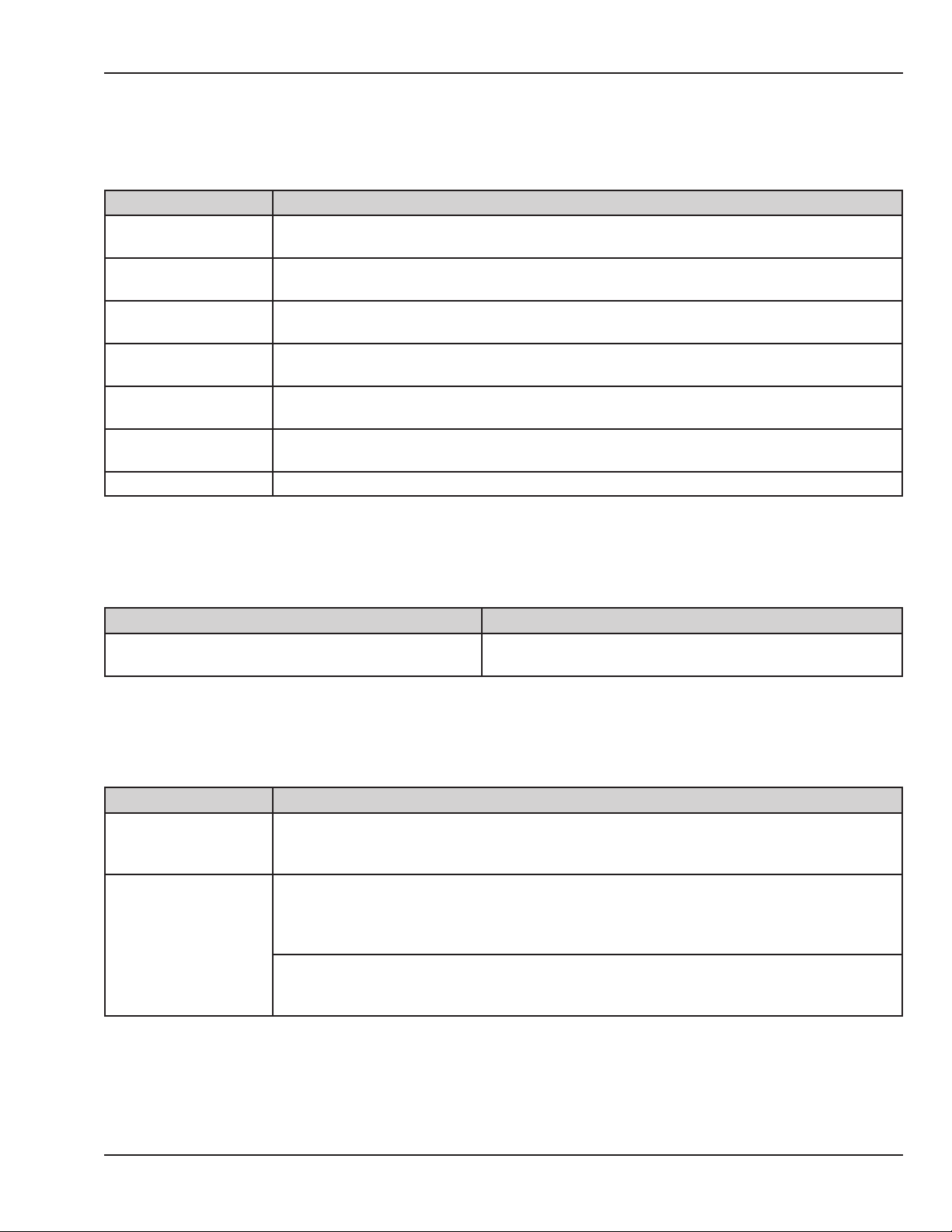
4.4.17 System Failure 19
System failure 19 indicates: No Audio Frequency.
Cause(s) Action(s)
Defective battery
Defective scale.
Defective scale
harness.
Defective Servo Oxygen
board.
Defective Servo Oxygen
cable.
Defective audio circuit
on control board.
Defective control board Replace the control board.
Battery is only used for power fail. Try powering up the unit with the battery disconnected. If
the error clears, replace the battery.
Disconnect scale connector at probe panel. Power cycle the unit. If the error clears, replace
the scale.
Disconnect scale harness from J7 on the control board. Power cycle the unit. If the error
clears, replace the scale harness.
Disconnect the RS485 harness from J8 on the Servo Oxygen board. Power cycle the unit. If the
error clears, replace the Servo Oxygen Board.
Disconnect RS485 bus cable from J6 on the control board. Power cycle the unit. If the error
clears, replace the RS485 cable going to the Servo Oxygen board.
Replace socketed IC U22 on control board. If failure persists, replace the control board.
Chapter 4: Troubleshooting
4.4.18 System Failure 20
System failure 20 indicates: Display WDOG Time Out.
Cause(s) Action(s)
Display driver board software is not performing
correctly.
Replace the display driver board.
4.4.19 System Failure 22
System failure 22 indicates: During operation, neither the radiant heater nor the incubator heater will turn ON.
Cause(s) Action(s)
Power down the unit. During the system tests after power-up the unit should detect system
Refer to other errors.
Error reading distorted
line signal.
failure 15, or Radiant heater failure or bed heater failure. Follow the instructions in this manual
for those failures.
Check the revision of the relay board. The revision code is located in a triangle printed on the
component side of the PCB. Refer to relay board Figure 6-41 (revision 10 or higher) and Figure
6-42 (revision 9 or lower). If the relay board is revision 10 or lower, replace with revision 13 or
higher relay board.
If you have replaced the relay board with revision 13 or higher and you still have an
intermittent problem, refer to the instructions in this manual for system failure 15 (section
4.4.13).
© 2001 by Datex-Ohmeda, Inc.. All rights reserved. 6600-0343-000 104 49
Page 78

Chapter 4: Troubleshooting
4.4.20 System Failure 23
System failure 23 indicates: During operation the system was unable to turn OFF either the radiant heater or
the incubator heater.
Cause(s) Action(s)
Other errors.
Defective relay board. If system failure 23 persists without system failure 16, replace the relay board.
Power down the unit. During the system tests after power-up the unit should detect system
failure 16. Follow the instructions in this manual for this failure.
4.4.21 System Failure 25
System failure 25 indicates: Fan rotation is not being detected.
NOTE: System failure 25 and FAN FAILURE are both triggered by the optical fan sensor not detecting the fan.
If this occurs at power-up a system failure 25 will activate. If it occurs after the power tests are completed the
FAN FAILURE alarm will activate.
Circumstance(s) Cause(s) Action(s)
Fan not connected. Check jack.
Fan is not turning
Fan is turning
Fan or fan hub not
seated properly.
Defective relay board. Replace relay board.
Defective fan motor. Replace fan motor.
Fan is turning too slow.
Old design fan.
Defective or obstructed
optical sensor. Sensor
holder or sensor gasket
dirty or crazed.
Defective 50 pin
ribbon cable between
the relay and control
board.
Defective relay board. Replace relay board.
Verify the fan hub is properly seated all the way down on the fan
shaft and is seated in the groove at the top of the hub.
Check fan speed in service mode, should be about 1500 RPM in high
fan speed. Note that this RPM measurement is only tested during the
power up tests.
Replace with new design fan. The new fan can be identied by the
grooves molded in the 2 black areas on the bottom of the fan (side
facing the heat sink). The old fan has smooth surfaced black areas.
Check that sensor, sensor holder, and gasket and free of dirt or other
contaminants. Clean or replace.
Check for continuity on pin 9 (AIRFLOW). If defective replace cable.
4.4.22 System Failure 26
System failure 26 indicates: During the power up tests, the system was unable to turn o safety relay 1.
Cause(s) Action(s)
Defective relay board. Replace the relay board.
50 6600-0343-000 104 © 2001 by Datex-Ohmeda, Inc.. All rights reserved.
Page 79

Chapter 4: Troubleshooting
4.4.23 System Failure 27
System failure 27 indicates: Defective non-volatile memory.
Cause(s) Action(s)
Defective circuit on control board. Replace the control board.
4.4.24 System Failure 28
System failure 28 indicates: During operation, the display driver board lost communication with control board.
Cause(s) Action(s)
Refer to system failure 0.Power down the unit, during the self-test the unit should detect system failure 0. Follow the
instructions for system failure 0.
Defective at ribbon
cable between control
board and display
board.
If system failure 28 persists without system failure 0, replace the at ribbon cable between
control board and display board.
4.4.25 System Failure 29
System failure 29 indicates: Defective signal on control board.
Cause(s) Action(s)
Defective control board Replace the control board.
4.4.26 System Failure 30
System failure 30 indicates: Mains voltage reading LV1 is outside of the expected range.
Cause(s) Action(s)
Mains Voltage Comp Circuit is not calibrated correctly. Calibrate the line voltage.
High or low mains voltage. This failure is triggered if the
mains voltage is outside the following ranges:
• 100V: 80-115V
• 115V: 95-132V
• 230V: 195-270V
Defective 50 pin ribbon cable between the relay and
control board.
Connect to proper mains voltage source
Check for continuity on pin 48 and 49 (LineComp1,2) If
defective replace cable.
© 2001 by Datex-Ohmeda, Inc.. All rights reserved. 6600-0343-000 104 51
Page 80

Chapter 4: Troubleshooting
Cause(s) Action(s)
Measure the voltages at the relay board:
• J37 pin 48-45 and J37 pin 49-45.
• If mains voltage 100/115 = 3-5 volts, dierence
Defective relay board.
within 0.4 volts.
• If mains voltage 230 = 7-10 volts, dierence within
0.8.
• If not, replace the relay board.
Defective control board. If the voltages are OK replace the control board.
4.4.27 System Failure 33
System failure 33 indicates: Defective RH Solid State Relay.
Cause(s) Action(s)
Defective RH Solid State Relay. Replace relay board
4.4.28 System Failure 34
System failure 34 indicates: Software revision level does not match.
Cause(s) Action(s)
The software revision of the control board and the
display board are not compatible
This error may occur after replacing the control/display board.
Be sure to install the software provided in the control/display
board. Replace the System Software.
4.4.29 System Failure 35
System failure 35 indicates: Wrong dipswitch set up.
Cause(s) Action(s)
Switches set wrong Check the 8 position dipswitch on the control board. Verify that Switch 1 and Switch 2 are on.
Defective control board. Replace control board.
4.4.30 System Failure 36
System failure 36 indicates: LV1 diers from LV2 by >10% of LV2.
Cause(s) Action(s)
Mains Voltage Comp Circuit is not calibrated correctly. Calibrate the line voltage.
Defective 50 pin ribbon cable between the relay and
control board.
52 6600-0343-000 104 © 2001 by Datex-Ohmeda, Inc.. All rights reserved.
Check for continuity on pin 48 and 49 (LineComp1,2) If
defective replace cable.
Page 81

Chapter 4: Troubleshooting
Cause(s) Action(s)
Measure the voltages at the relay board:
• J37 pin 48-45 and J37 pin 49-45.
• If mains voltage 100/115 = 3-5 volts, dierence
Defective relay board.
within 0.4 volts.
• If mains voltage 230 = 7-10 volts, dierence within
0.8.
• If not, replace the relay board.
Defective control board. If the voltages are OK, replace the control board.
4.4.31 System Failure 37
System failure 37 indicates: Defective Switches (software 1.60 or higher).
Cause(s) Action(s)
Both canopy up and canopy down
position switches are closed.
Use the service screen to determine which switches are on. Use an ohmeter to
test the switches and cabling. Refer to the Tips section (4.6.5).
4.4.32 System Failure 38
System failure 38 indicates: Software has detected that door switches show that heater doors are both open
and closed (which is not physically possible).
Cause(s) Action(s)
Defective switches or
harness
Use the SERVICE SCREEN to determine which switches are on. Use an ohmeter to test the
switches and cabling. Refer to the Tips section (4.6.5).
4.4.33 System Failure 50
System failure 50 indicates: Incorrect display driver board System Software checksum.
Cause(s) Action(s)
Defective System Software PROM on display driver board. Install new system software 6600-0234-850.
Defective display driver board. If the system failure persists, replace display driver board.
4.4.34 System Failure 51
System failure 51 indicates: Display Defective SRAM.
Cause(s) Action(s)
Defective SRAM circuit on the display driver board Replace the display driver board.
© 2001 by Datex-Ohmeda, Inc.. All rights reserved. 6600-0343-000 104 53
Page 82

Chapter 4: Troubleshooting
4.4.35 System Failure 52
System failure 53 indicates: Display No Timer2.
Cause(s) Action(s)
Defective display driver board. Replace the display driver board.
4.4.36 System Failure 53
System failure 53 indicates: Display Timer2 Too Fast.
Cause(s) Action(s)
Defective display driver board. Replace the display driver board.
4.4.37 System Failure 55
System failure 55 indicates: Display board On Line Self Test Failure.
Cause(s) Action(s)
Defective display driver board. Replace the display driver board.
4.4.38 System Failure 60
System failure 60 indicates: Line Circuit Failure.
Cause(s) Action(s)
Failure in relay board LV2 calibration circuitry during calibration. Replace relay board.
4.4.39 System Failure 98
System failure 98 indicates: Overow.
Cause(s) Action(s)
Software on the control board is not performing
correctly.
Replace the control board.
4.4.40 System Failure 99
System failure 99 indicates: Logic problem on the control board.
Cause(s) Action(s)
Software on the control board is not performing
correctly.
54 6600-0343-000 104 © 2001 by Datex-Ohmeda, Inc.. All rights reserved.
Replace the control board.
Page 83

4.5 Troubleshooting Symptoms
Symptom Possible Cause Action
Use an ohmmeter to verify the speaker resistance is about 8
ohms at relay board connector J40, pins 5-6. If defective, raise
the lower shroud and measure at 6 pin connector to determine if
speaker or harness is defective.
Replace the control board.
Cycle power after compartment probe is plugged in.
Remove reservoir, but take care because surface may be hot!
Check that the white reservoir switch button moves freely. If it is
stuck in the closed position it should be replaced with the new
style. (6600-1298-500)
Check resistance of reservoir switch at relay board harness J32,
2-3. Switch should be closed when reservoir is closed and open
when reservoir is open.
Check for continuity on pin 6 (RHBOTTLE). If defective, replace
cable.
Try raising/lowering canopy using the hand switches. Check
Setup screen (wrench symbol) or service screen to see if pedal
switches are disabled.
Check the toroidal transformer. Refer to the Tips section (4.6.12).
Replace transformer if defective.
Replace relay board.
Check fuses F5, F6 on the relay board.
Check for continuity on pins 23, 24, 26, 27, 34 (motor control and
safety relay 2 control signals). If defective, replace the cable.
Replace relay board.
No audio alarm.
Unit equipped with
servo-humidity but
RH setpoint only
shows 1-10.
ADD WATER
message stays on
even after water
has been added.
Elevating base AND
Canopy will not go
up or down.
Defective speaker or harness.
Audio driver circuitry on
control board is defective.
Unit was powered on and the
compartment probe was not
plugged in at the probe panel
(only on old style units with
connector)
Defective humidity sensor Replace the humidity sensor.
Defective control board. If problem persists, replace control board.
Reservoir switch button is
jammed (only on units with old
style button).
Defective reservoir switch.
Defective 50 pin ribbon cable
between the relay and control
board.
Defective relay board. Replace relay board.
Defective control board. Replace control board.
Pedal switches are disabled on
nurse setup screen or service
screen.
Defective toroidal transformer
No mains input to the toroidal
transformer.
Output voltage from the
toroidal transformer is OK.
Defective fuse on relay board.
Defective 50 pin ribbon cable
between the relay and control
board.
Output voltage from the
toroidal transformer is OK.
Fuses on relay board are OK.
Defective relay board.
Chapter 4: Troubleshooting
© 2001 by Datex-Ohmeda, Inc.. All rights reserved. 6600-0343-000 104 55
Page 84

Chapter 4: Troubleshooting
Symptom Possible Cause Action
Elevating base will
not go up or down,
canopy works OK.
Canopy will not go
up or down with
pedal switches or
hand switches,
Elevating base
works OK.
Canopy works in
one direction but
not the other.
Canopy travels
down part way then
stops or goes very
slow for the last
part.
Canopy rises slowly
and stops before
doors are opened
fully.
Canopy is clouded.
Unit will not switch
to Baby Control
Mode.
Pedal switches are disabled on
nurse setup screen or service
screen.
Defective elevating base
motor.
Defective relay board. Replace relay board.
Canopy motor turns. Defective
belt or clutch.
Canopy motor does not turn.
Defective canopy motor
Canopy motor does not turn.
Defective 50 pin ribbon cable
between the relay and control
board.
Canopy motor does not turn.
Defective relay board.
Defective canopy motor.
Defective 50 pin ribbon cable
between the relay and control
board.
Defective relay board. Replace relay board.
An object fell into the opening
behind the radiant heater
oppy door.
Broken rungs in rail drive belt Inspect belt. Refer to the Tips section (4.6.10).
Use of alcohol or handdisinfectants
A patient probe is plugged into
Jack 2 on the probe panel.
Baby Control is disabled on
Service screen.
Check Setup screen (wrench symbol) or service screen to see if
pedal switches are disabled.
Check the voltage to the elevating base motor. Refer to the Tips
section (4.6.9). If the voltage is OK, replace the elevating base
assembly.
Check rail drive belt and clutch. Refer to the Tips section (4.6.10).
Check the voltage to the canopy motor. Refer to the Tips section
(4.6.9). If voltage is OK, replace the canopy motor.
Check for continuity on pins 23, 24, 26, 27, 34 (motor control and
safety relay 2 control signals). If defective, replace the cable.
Replace relay board.
Check the voltage to the canopy motor for both up and down
movement. Refer to the Tips section (4.6.9). If OK, replace the
canopy motor/gearbox.
Check for continuity on pins 23, 24, 26, 27 (motor control signals).
If defective, replace the cable.
Check that the oppy door, located behind the radiant heater
moves freely. Look to be sure nothing has fallen behind the door.
Replace canopy.
Disconnect probe from Jack 2 (unit will only allow Baby Control
operation with a single probe in Jack 1).
Select BOTH for Patient Control on service screen to activate
Baby Control.
56 6600-0343-000 104 © 2001 by Datex-Ohmeda, Inc.. All rights reserved.
Page 85

Symptom Possible Cause Action
Disconnect scale connector at probe panel. Power cycle the unit.
If error clears replace the scale.
Disconnect scale harness from J7 on the control board. Power
cycle the unit. If error clears replace the scale harness.
Disconnect the RS485 harness from J8 on the Servo Oxygen
board. Power cycle the unit. If the error clears, replace the Servo
Oxygen Board.
Disconnect RS485 bus cable from J6 on the control board. Power
cycle the unit. If the error clears, replace the RS485 cable going
to the Servo Oxygen board.
Remove the electrical enclosure cover and disconnect the
battery. Power down and power up again. If the unit powers up,
replace the 9V battery (66001024600).
Verify power supply voltages at J23 on display driver board.
Unit will not power
up, alarm sounds.
Defective scale.
Defective scale harness.
Defective Servo Oxygen board.
Defective Servo Oxygen cable.
Defective battery.
Defective power supply. Check power supply voltages. Refer to the Tips section (4.6.4).
Chapter 4: Troubleshooting
Baby Hot or Baby
Cold alarms
activated while unit
is in Manual Mode.
Air Temp >38C or
Air Temp >40C
alarm activated
even though
compartment temp
is < alarm.
Bed warms up
very slowly, may
not reach set
temperature.
Unit always powers
up in service screen
mode.
Defective power harness to
display board.
• +5V 1-2
• +12V 1-3
• +5STBY 1-4
Disconnect ribbon cable from J6 on control board. Power up unit.
Defective display driver board
Defective control board. Replace control board.
MANUAL TEMP alarm is
selected on the Setup screen
Alarm is not designed to
automatically reset after
alarm condition is resolved.
One of the bed heater
cartridges is defective.
Defective dipswitch setting
Override switch (>37C) on
control panel shorted
Girae logo should appear on display. After about 70 seconds
the audible alarm sounds. If the logo does not appear replace
the display driver board.
Select OFF for MANUAL TEMP alarm on Setup screen.
Push the alarm silence button to clear the alarm.
Feel the heat sink to see if one side is cooler than the other. Use
care, since the heat sink can reach temperatures as great as
121C (250F). Replace the cartridge on the cool side.
Check position 8 on the control board dipswitch. Should be set to
O position.
Check switch on switch diagnostic screen.
© 2001 by Datex-Ohmeda, Inc.. All rights reserved. 6600-0343-000 104 57
Page 86

Chapter 4: Troubleshooting
Symptom Possible Cause Action
Defective circuit on control
Screen refreshes
every few seconds
while scale is
attached.
Noise from speaker
on power down.
Fan is running in
high speed but
no FAN ALWAYS
IN HIGH SPEED
message and the
Boost Air Curtain
Indicator is not lit.
Bed will not lock in
tilt position.
Baby Cold or Baby
Hot Alarm does not
trigger at 0.5ºC or
1.0ºC in Air Control
mode.
Humidier reservoir
is crazed (has
hairline cracks).
Humidier reservoir
has scaling.
board (Unbiased RS485 bus
during idle state).
Defective scale.
Defective scale harness.
Microprocessor does not hold
reset during power o.
This is normal condition for
90 minutes after power up, 45
minutes after transition from
open to closed bed mode,
and during other conditions
as determined by the heat
control software.
Tilt ball not engaged in nger
pocket latch.
Tilt brake pad failure. Replace the tilt brake .
Manual Temp. Alarm is
disabled on Service Screen.
Sterilization Replace humidier reservoir.
Use of tap water Replace humidier reservoir.
Replace control board with revision 17 or higher.
Disconnect scale connector at probe panel. Power cycle the unit.
If error clears replace the scale.
Disconnect scale harness from J7 on the control board. Power
cycle the unit. If error clears replace the scale harness.
If noise is excessive, replace control board with revision 17 or
higher.
To check HIGH and LOW fan speed, power up the unit. After the
power up sequence is complete, hold down the Boost Air Curtain
button and press the decrease temperature button to place the
unit into low fan speed. The Boost Air Curtain button will now
toggle the fan between high and low speeds.
Tilt the head of the bed platform all the way down while holding
the latch open, then let the latch close to capture the tilt ball.
(Refer to “Disassembly for complete cleaning” in the Operation
and Maintenance manual.)
Enable Manual Temp. alarm.
4.6 Additional Troubleshooting Tips
Following are tips on taking many of the measurements and diagnosing the failures that are referred to in the
troubleshooting charts. For some tips it may be necessary to determine the revision level of the relay board.
The revision code is located in a triangle printed on the component side of the PCB. Refer to relay board Figure
6-41 (revision 10 or higher) and Figure 6-42 (revision 9 or lower).
4.6.1 Raising and Lowering the Canopy or Elevating Base
In the event of an OmniBed system failure, it may be possible to raise or lower the canopy or the elevating base
in the service mode. Hold down the override button (>37) to bring up the service screen. The pedals are now
activated to assist in troubleshooting or transportIf the switches still do not operate it may be possible to raise
the canopy and raise or lower the elevating base using the pedal function on page 2 of the service screen.
58 6600-0343-000 104 © 2001 by Datex-Ohmeda, Inc.. All rights reserved.
Page 87

Chapter 4: Troubleshooting
4.6.2 Incubator Heaters and Bed Safety Thermostat
There are two 115 volt incubator heaters rated at 225 watts at 104 volts and mounted at opposite ends of
the incubator heat sink. They are always connected in parallel and are powered by isolated 115 volts from the
heater isolation transformer. This voltage is switched by the incubator SSR.
The resistance of each heater is about 48 ohms and they are in parallel so you should measure about 24 ohms.
Note that the bed safety thermostat is in series with the heaters so if the reading is open circuit you must take
readings at the connectors under the bed to determine which is defective.
To measure the incubator heater resistance on units with revision 9 or lower relay boards, disconnect the black
wire on the incubator SSR and the white wire on the output of the isolation transformer and measure between
these 2 wires.
To measure the incubator heater resistance on units with revision 10 or higher relay boards, disconnect the
black wire on the incubator SSR and the connector from J54 on the relay board. Measure between harness
connector pin 4, and the black wire.
The incubator heater and bed safety thermostat resistance can also be measured by the removing the bottom
cover and measuring directly at the components.
4.6.3 Radiant Heater
The 115 volt radiant heater is rated at 225 watts at 104 volts. It is powered by isolated 115 volts from the
heater isolation transformer switched by the radiant warmer SSR.
The resistance of the radiant heater is about 24 ohms.
To measure the radiant heater resistance on units with revision 9 or lower relay boards disconnect the brown
wire on the warmer SSR and the white wire on the output of the isolation transformer and measure between
these 2 wires.
To measure the radiant heater resistance on units with revision 10 or higher relay boards disconnect the brown
wire on the radiant heater SSR and the connector from J54 on the relay board. Measure between harness
connector pin 3, and the brown wire.
The radiant heater resistance can also be measured by removing the heater housing and measuring on the
radiant heater harness.
4.6.4 Power Supplies
The 5V and 12V supplies are generated on the power supply.
+5STBY is generated on the relay board. These voltages are distributed to the control board, display driver
board, servo oxygen board, and expansion slots through a harness with a series of 4 pin connectors. The
easiest place to measure the power supplies is at one of the spare 4 pin connectors on this power bus.
© 2001 by Datex-Ohmeda, Inc.. All rights reserved. 6600-0343-000 104 59
Page 88

Chapter 4: Troubleshooting
Signal Location Wire Color Value
+5V J42 pins 1-2 Orange and blue 4.75 to 5.25
+5VSTBY J42 pins 1-4 Orange and green 4.75 to 5.25
+12V J42 pins 1-3 Orange and red 10.8 To 13.2
The 5VSTBY should also be present during power fail.
+5VAN and -5VAN are generated on the control board and are only used on the control board. They can be
measured on the test points on the control board.
Signal Location Value
+5V TP2 pins 1-4 4.75 to 5.25
+5VSTBY TP2 pins 3-4 4.75 to 5.25
+5AN TP1 pins 5-6 4.75 To 5.25
-5AN TP1 pins 4-6 -4.0 To -5.5
4.6.5 Switches/Thermostat
Use switch status diagram on the second service screen to assist in troubleshooting the switches.
Canopy up detect Relay bd J36 pins 1-2 Closed when canopy is up
Canopy down detect Relay bd J36 pins 7-8 Closed when canopy is down
Canopy middle Relay bd J36 pins 4-5 Closed momentarily during transition
Heater doors open Relay bd J31 pins 2-3 Closed when both heater doors are open
Heater doors closed Relay bd J31 pins 1-3 Closed when both heater doors are closed
Humidity reservoir Relay bd J32 pins 2-3 Closed when reservoir is closed
Add water thermostat Relay bd J32 pins 1-3 Opens when reservoir needs water
Canopy foot control
Left or Right Relay bd J40 pins 3-4 Closed when either switch is pressed
E-base foot control
Left or right up Relay bd J40 pins 2-4 Closed when either switch is pressed
Left or right down Relay bd J40 pins 1-4 Closed when either switch is pressed
The following switches are membrane switches. When closed the resistance should be less than 200 ohms.
Display touch panel switches
Alarm Silence Display Driver bd J21 pins 1-2 Closed when switch is pressed
>37 degrees Display Driver bd J21 pins 1-3 Closed when switch is pressed
Servo Control Display Driver bd J21 pins 1-4 Closed when switch is pressed
Up Display Driver bd J21 pins 1-5 Closed when switch is pressed
Down Display Driver bd J21 pins 1-6 Closed when switch is pressed
Manual Mode Rad. Htr Display Driver bd J21 pins 1-7 Closed when switch is pressed
60 6600-0343-000 104 © 2001 by Datex-Ohmeda, Inc.. All rights reserved.
Page 89

Chapter 4: Troubleshooting
Intervention Display Driver bd J21 pins 1-8 Closed when switch is pressed
Manual Mode Inc. Display Driver bd J21 pins 1-9 Closed when switch is pressed
Canopy hand control
Left up Relay bd J35 pins 2-4 Closed when switch is pressed
Left down Relay bd J35 pins 3-4 Closed when switch is pressed
Right up Relay bd J35 pins 6-5 Closed when switch is pressed
Right down Relay bd J35 pins 7-5 Closed when switch is pressed
4.6.6 Humidier Heater/Safety Thermostat
The humidier has two separate heater elements rated at 225 watts at 104 volts. They are connected in
parallel for 115 volt operation and in series for 230 volt operation. The humidier safety thermostat is in series
with the heater. It opens at 130 +/-5 C and closes at 90 +/-8 C. Measure the resistance at J53.2 to J53.3.
The resistance of each heater is about 144 ohms so it should measure about 72 ohms for 115 units, 288 ohms
for 230 units.
4.6.7 Compartment Air Probe and Patient Probes
Use the service screen to read the temperature of the compartment and patient probes.
There are two thermistors in each air probe or patient probe. During stable temperature conditions the
thermistors should read the same resistance within a few ohms.
Patient probe #1 Control bd J4 pins 1-3, 2-3
Patient probe #2 Control bd J2 pins 1-3, 2-3
Compartment Air probe Control bd J1 pins 1-2, 3-4
Temperature (C) Resistance (Ohms)
20 12527
25 10000
30 8037
35 6500
© 2001 by Datex-Ohmeda, Inc.. All rights reserved. 6600-0343-000 104 61
Page 90
Chapter 4: Troubleshooting
4.6.8 Heat Sink Sensor Thermistor
Use the service screen to read the resistance of the heat sink sensor.
Thermistor Control bd J3 pins 1-2
Temperature (C) Resistance (Ohms)
20 25000
25 20000
30 16102
35 13048
40 10636
80 2506
90 1827
100 1353
110 1017
120 775
4.6.9 E-base Motor and Canopy Motor
If you must replace a footswitch when the bed is all the way down, use pedal screen on service screen to raise
or lower the bed.
To troubleshoot the canopy clutch and roll pins, run the e-base all the way up. Take the bottom end cap o the
rail and the back panel o the electrical enclosure. Use a ash bulb to look up into the rail and see what moves
when the canopy slips. If the motor coupler is turning, then either the slip clutch or one of the roll pins is missing
or defective. If the clutch turns and not the sprocket, then the problem is a defective slip clutch. If neither turns,
the problem is probably a sheared roll pin.
The e-base motor and canopy motors are driven by the same circuits. The e-base is always driven at 24 volts
DC (acceptable range 24-32), and the canopy motor is driven at 24 volts (acceptable range 24-32) when going
up and 12 volts (acceptable range 12-16) when going down.
62 6600-0343-000 104 © 2001 by Datex-Ohmeda, Inc.. All rights reserved.
Page 91

Chapter 4: Troubleshooting
The following chart shows the control signal values and the output voltages for each of the motor conditions.
Control Signals, Relay Board E-base Canopy
Switch
J37 pin 23
J37 pin 26
J37 pin 24
J37 pin 27
J45-1 J45-2 J46-1 J46-3
24V SELECT
Raise
canopy
Lower
canopy
Raise
E-base
Lower
E-base
None NA 1 NA NA NA NA NA NA
0 0 1 1 NA NA +24V Gnd
1 0 0 1 NA NA Gnd +12V
0 0 1 0 +24V Gnd NA NA
0 0 0 0 Gnd +24V NA NA
E/H ACTIVATE
NVERTPOLARITY
E/H SELECT
4.6.10 Rail Lift Belt Failure
The following symptoms might be observed that indicate possible rail lift belt (drive belt) failure (rail belts that
have broken rungs after extended use):
• Canopy rises slowly and sticks just when doors are opening (4-6 inches from top of canopy travel)
• Heater doors don’t open fully (lift hasn’t traveled far enough to complete door opening mechanism)
• “In transition” alarm sounds when:
• Canopy is not all the way up to activate microswitches, OR
• Heater doors aren’t fully open to activate their microswitches
If these symptoms exist, check for rail lift belt failure by doing the following:
1. Remove the canopy motor.
2. Slide up the decorative strip to expose the endcap screw. Remove the lower endcap.
3. Using a bright ashlight pointing up in the bottom of the rail, look inside the rail assembly through the
shipping lock-down screw slot near bottom of the rail. Look toward the back (North) to observe rail lift belt.
4. Manually raise and lower the canopy, slowly. (If possible, have a second person do this for you.) While
the canopy is being slowly raised and lowered, visually inspect the belt (via the screw slot) to determine
whether there are any rungs on the belt that are stripped/broken.
5. Inspect the entire belt by manually sending the canopy through its full cycle, especially the links as the belt
nears the top of upward travel.
© 2001 by Datex-Ohmeda, Inc.. All rights reserved. 6600-0343-000 104 63
Page 92

Chapter 4: Troubleshooting
When ordering the new belt, order the following parts as it is sometimes dicult to remove the screws from the
belt block adjuster without stripping the heads. If this happens it is easiest to just replace the block and screws.
Part Number Quantity Description
6600-1372-500 1 Lift Belt
6600-1360-500 1 Belt Block Cover
6600-1357-500 1 Belt Adjuster, Bottom
6600-1151-400 2 Screw, M3X10 Flat Head Socket
NOTE: For instructions on replacing the belt, refer to section 5.4.3.4.
4.6.11 Troubleshooting the 50 Pin Ribbon Cable
All of the communication between the control and relay boards passes through the 50 pin ribbon cable. Many
of the troubleshooting procedures in this manual recommend that you verify continuity for specic pins in the
cable. Because it is dicult to remove and measure the cable without possibly changing the resistance, it is
suggested that you keep a spare 50 pin ribbon cable to use as a troubleshooting tool.
4.6.12 Troubleshooting the Toroidal Transformer
Perform the following tests in service mode. The referenced voltages should always be present when the unit is
in service mode. In normal operating mode, the voltages are not present if safety relay 2 contacts are open.
1. Check the output voltage of the toroidal transformer at J44 pins 1-2 and at J44 pins 3-4. Voltages should
be about 15 volts AC .
2. If the voltage is not present verify that mains voltage is present at the primary input to the toroidal
transformer in service mode. This voltage can be measured at relay board connector J51 pins 1-2. It can
also be measured at the conguration plug on the toroidal transformer pins 1-4.
3. If the primary voltage is present and there is no output voltage, the toroidal transformer is defective.
4. If the primary voltage is not present, then replace the relay board.
4.6.13 Interpreting Serial Numbers
Datex-Ohmeda products have unit serial numbers with coded logic which indicates a product group code,
the year of manufacture, and a sequential unit number for identication. The serial number is in the following
format:
AAAX11111
The X represents an alpha character indicating the year the product was manufactured; H = 2004, J = 2005,
etc. I and O are not used.
64 6600-0343-000 104 © 2001 by Datex-Ohmeda, Inc.. All rights reserved.
Page 93

Chapter 4: Troubleshooting
4.7 Servo Controlled Oxygen
4.7.1 Servo Controlled Oxygen Service Screen
To access the service screens, hold in the override button (>37) during power up until the software revision
screen appears. Release the button and the rst service screen will appear. Select DOWN on the rst screen to
go to the second service screen. Select Servo O2 to bring up the Servo Controlled Oxygen service screen.
Figure 4-7 Servo Controlled Oxygen Service Screen
Item Description
V1 Select to open or close supply valve one in the valve housing located beneath the electrical enclosure.
V2 Select to open or close supply valve two in the valve housing located beneath the electrical enclosure.
Select to open or close calibration valve in the sensor housing located beneath the bed. Open is
calibration position and closed is the normal operation position. The calibration fan is on and the cooling
VC
K1 Select to open or close the relay on Relay PCB that powers the valves.
Cal 02 Initiates calibration routine.
oxygen0 Oxygen reading in percent from rst sensor cell:
oxygen1 Oxygen reading in percent from second sensor cell:
sensor0 Voltage output in millivolts from rst sensor cell.
fan is o when VC is open.
NOTE: The cooling fan is on whenever the Servo Controlled Oxygen service screen is selected and VC is
closed.
© 2001 by Datex-Ohmeda, Inc.. All rights reserved. 6600-0343-000 104 65
Page 94

Chapter 4: Troubleshooting
Item Description
Voltage output in millivolts from second sensor cell.
sensor1
NOTE: The following information applies to the oxygen0, oxygen1, sensor0, and sensor1 values:
• For software version 1.40 or previous versions, 23 mv - 280 mv = 21% - 100% O2.
• For software version 1.50 or later versions, 5 - 90 mv = 21 - 100% O2.
temp
humidity Relative humidity in percent read from a sensor inside the sensor housing located beneath the bed.
Temperature in degrees Celsius read from a sensor inside the sensor housing located beneath the bed.
Refer to temperature to resistance curve in the Tips section (4.7.3).
4.7.2 Servo Controlled Oxygen Alarm Messages
Alarm Message Meaning Cause Action
Low Oxygen
High Oxygen
Sensor1 reading
is> 3% below the
oxygen set point
7 minutes after a
set point change
or the OmniBed
canopy was
closed.
Sensor1 reading
more than 3%
above set point
Low O2 supply pressure or
ow.
Inlet screen occluded.
Air leaks into infant
compartment.
Supply Valve not opening.
Endcap safety valve not
opening.
Calibration valve is not
closing.
Infant compartment vents
occluded.
Oxygen set point recently
lowered.
Supply valve(s) not closing.
Be sure supply is greater than 45psi (310 kPa)
and ow rate is greater than 45 L/min. If ow rate
is <45 check that the inlet screen in the regulator
is not occluded. Clean or replace screen.
Be sure all doors and portholes are closed.
Check supply valves. Refer to the Tips section
(4.7.3).
Check valve and spring assembly. Refer to the
Tips section (4.7.3).
Check the calibration valve. Refer to the Tips
section (4.7.3).
Check to be sure that the two vents in the infant
compartment under the bed are not occluded.
Allow time for oxygen level to drop.
Check supply valves and kinked hoses. Refer to
the Tips section (4.7.3).
66 6600-0343-000 104 © 2001 by Datex-Ohmeda, Inc.. All rights reserved.
Page 95

Alarm Message Meaning Cause Action
In service mode sensor0 and sensor1 should be
23-280. If outside this range replace the sensors.
If in range ensure oxygen0 and oxygen1 read
within 3% of each other or replace the sensors.
Be sure sensor housing is seated properly and
the retaining screws are tight. Be sure sensor
gaskets are in place and the tubing is seated
correctly in the connectors. Check to be sure that
the two vents in the infant compartment under
the bed are not occluded.
Measure the voltage at J85.8-J85.7(sensor0)
and J85.6-J85.7(sensor1) and compare them
to displayed sensor0 and sensor1. If the
measurement is the same as the displayed,
check the cable and sensor contacts.
If the measurement is not the same as the
displayed, replace the Servo O2 board.
Replace display software with 1.62 or higher.
Test the cooling fan. Refer to the Tips section
(4.7.3).
Disconnect the cable and measure the resistance
of the thermistor between J85.4 and J85.5. Refer
to R/T chart (the temperature to resistance curve)
in the Tips section (4.7.3). If sensor is shorted,
open, or values don’t agree with the R/T chart,
replace the sensor plug assembly or the cable.
If resistance is in range replace the servo O2
board.
Measure the humidity sensor voltage between
J85.2 and J85.1. If the voltage is outside the
range of 0.7V- 4.0V, replace the sensor plug
assembly.
If it is in the correct range, replace the servo O2
Board.
Replace microcontroller U6 on the Servo O2
board.
Oxygen Probe
Failure
O2 Cal Lost-No
O2
Oxygen System
Failure 1
Oxygen System
Failure 2
Oxygen System
Failure 3
One of the
sensors is reading
out of range
(23-280 millivolts
on units with
1.3 software
or higher) or
the dierence
between the two
O2 sensors is
above 3%.
Servo oxygen
unit has never
been calibrated.
Unit will not
operate until
initial calibration
is performed.
Cell voltage less
than 33 mV.
The sensor
plug thermistor
temperature
reading is out
of the range:
15C-55C.
The RH reading is
out of valid range:
1-99. When out of
range it displays 0
in service mode.
The checksum
test performed
during power up
testing failed.
Defective Sensor(s)
Leak or occlusion in sensor
housing area.
Defective cable or
connection.
Defective Servo O2 board.
Perform oxygen calibration. Run calibration.
Earlier software versions did
not store voltages this low.
Unit is cold: <15 degrees C. Allow unit to warm up.
Cooling fan is not running
when the sensor housing
temperature gets above 50
degrees.
Defective sensor plug
thermistor or cable.
Defective servo O2 board.
Defective sensor plug.
Defective servo O2 board.
Defective Microcontroller.
Chapter 4: Troubleshooting
© 2001 by Datex-Ohmeda, Inc.. All rights reserved. 6600-0343-000 104 67
Page 96

Chapter 4: Troubleshooting
Alarm Message Meaning Cause Action
Analog to digital
converter circuit
self test failed.
Oxygen System
Failure 4
Check O2 supply
Oxygen System
Failure 5
Oxygen System
Failure 6
Oxygen System
Failure 7
Calibration failed
The reading
of Vtest is out
of the valid
range:1.216V-
1.254V.
After calibration,
both supply
valves are
opened and after
approximately 20
seconds, sensor1
reading is not
greater than 23%.
Check O2 Supply
alarm has been
silenced twice
and the sensor1
reading is still not
greater than 23%.
The Girae
control board
cannot
communicate
with Servo O2
board.
Power up test
detected a
problem with the
watchdog circuit.
In calibration
mode, after 5
minutes, both
sensors are
not reading
between 23 and
55 millivolts so
the unit cannot
calibrate.
Defective Servo O2 board. Replace servo O2 board.
O2 supply is not connected.
Kinked hoses in sensor
housing.
O2 supply is not connected.
Calibration valve stuck in
calibration position.
Supply valves not opening.
Leak or occlusion in sensor
housing area.
Defective Servo O2 board. Replace servo O2 board.
Defective Cable.
Defective Servo O2 board. Replace Servo O2 board.
Calibration valve is not
opening or the calibration
fan is not turning on.
Defective sensors. Replace the sensors.
Verify O2 supply, minimum 45psi (310kPa) is
connected to the inlet.
Check hoses.
Verify O2 supply, minimum 45psi (310 kPa) and
45 L/min is connected to the inlet.
Check the calibration valve. Refer to the Tips
section (4.7.3).
Check supply valves. Refer to the Tips section
(4.7.3).
Be sure sensor housing is seated properly and
the retaining screws are tight. Be sure sensor
gaskets are in place and the tubing is seated
correctly in the connectors. Check to be sure that
the two vents in the infant compartment under
the bed are not occluded.
Check that the cable between the Girae control
board and the Servo O2 board is seated properly.
Check the calibration valve and fan. Refer to the
Tips section (4.7.3).
68 6600-0343-000 104 © 2001 by Datex-Ohmeda, Inc.. All rights reserved.
Page 97
Alarm Message Meaning Cause Action
Auxiliary source of
oxygen supply in patient
compartment.
Leak in the servoO2 system
supply valve.
Check the secondary sources, such as ventilator
or resuscitation bag.
Check supply valves. Refer to the Tips section
(4.7.3).
FiO2>26%
Elevated oxygen
levels in patient
compartment not
controlled by the
servo O2 system.
SENSITIVE TO ELECTROSTATIC DISCHARGE CAUTION
An Electrostatic Discharge (ESD) Susceptibility symbol is displayed to alert service personnel that the
part(s) are sensitive to electrostatic discharge and that static control procedures must be used to
prevent damage to the equipment.
4.7.3 Servo Controlled Oxygen Troubleshooting Tips
4.7.3.1 Check Supply Valves and Endcap Safety Valve
Chapter 4: Troubleshooting
Power up unit in service mode. Close the canopy. Select Servo O2 on second page. Be sure O2 is connected.
Open V1. You should hear gas ow. Close V1, open V2. You should hear gas ow. Close V2, gas ow should stop.
If supply valves are open an there is no gas ow, check that the endcap safety valve located in the bottom of
the rail is not stuck in the closed position. Check that the two-way valve is not occluded or the spring assembly
has not failed.
If both valves are not opening, test the fuses and supply valves. Disconnect J83 at the Servo O2 board. Measure
the resistance on harness pin 1 to pin 2. It should be the supply valve resistance (50 to 100 ohms). If not, the
fuse is opened or the supply valve is defective. Repeat for the second supply valve with pins 3 to 4. If the valves
check OK, the Servo O2 board is defective.
NOTE: With one supply valve open the ow rate should be a minimum of 35 L/min. With both supply valves
open, the minimum ow rate should be 40 L/min. If the ow rate is low, check that the regulator inlet screen is
not occluded.
4.7.3.2 Check Calibration Valve/Calibration Fan
The calibration valve is located beneath the chassis in the sensor housing. The calibration fan is mounted in
the sensor housing next to the calibration valve. Power up unit in service mode. Select Servo O2 on second
page. Open VC. This should open the calibrate valve and turn on the calibration fan. Verify the calibration fan
is running. If the fan is running then the Servo O2 board is OK and the calibration valve may be defective. If
the fan is not running check the control signal from the Servo O2 board to verify voltage is present when VC is
opened to determine if the fan or board is defective.
© 2001 by Datex-Ohmeda, Inc.. All rights reserved. 6600-0343-000 104 69
Page 98
Chapter 4: Troubleshooting
4.7.3.3 Check Cooling Fan
The cooling fan is mounted to the sensor housing door on the chassis cover. Power up unit in service mode.
Select Servo O2 on second page. The cooling fan should be running.
If fan is not running verify 10.0 - 13.2 Volts at J86-1 to J86-2. If voltage is present the fan is defective. If voltage
is not present the Servo O2 board is defective. Open VC, you should hear a click and the cooling fan should
stop. If the fan does not stop the Servo O2 board is defective.
4.7.3.4 Sensor Housing Temperature Sensor Temperature to Resistance Curve
Temperature Resistance
15C 15.720 kohm
25C 10.000 kohm
30C 8.056 kohm
35C 6.530 kohm
40C 5.326 kohm
45C 4.369 kohm
50C 3.604 kohm
60C 2.491 kohm
70 6600-0343-000 104 © 2001 by Datex-Ohmeda, Inc.. All rights reserved.
Page 99
Chapter 5: Repair Procedures
SENSITIVE TO ELECTROSTATIC DISCHARGE CAUTION
An Electrostatic Discharge (ESD) Susceptibility symbol is displayed to alert service personnel that the
part(s) are sensitive to electrostatic discharge and that static control procedures must be used to
prevent damage to the equipment.
WARNING:
After performing any repair or calibration, always perform the Service Checkout Procedure before
putting the unit back into service.
5.1 Canopy Removal for Replacement
1. If the unit has original canopy seals, plan ahead about canopy seal parts. Choose one of the following:
• If you plan to transfer the seal parts from the old canopy to the new, order the corner label set (66002358-100, set of two), as these cannot be reused.
• If you plan to replace the seal parts, order the Enhanced Seal Retrot Kit (M1208286).
2. Lock the rails in the intermediate position:
a. Raise the canopy.
b. Slowly lower the canopy until the rail locking screws align with the horizontal oblong holes in the rails.
(Refer to Figure 5-1.)
c. Use a 4 mm hex key to turn the rail locking screws counter-clockwise until they lock both rails in place.
3. Lower the elevating base to a convenient height for reaching the canopy.
4. Switch o the unit and disconnect the power cord.
5. Cover the bed with a sheet to catch any parts that may fall.
6. Remove the canopy from the unit:
a. Using a small straight-blade screwdriver, remove the six arrow clips that secure the sot beneath the
north end of the canopy. Remove the sot. (Refer to Figure 5-1.) Save the six arrow clips and sot for
later reinstallation.
© 2001 by Datex-Ohmeda, Inc.. All rights reserved. 6600-0343-000 104 71
Page 100
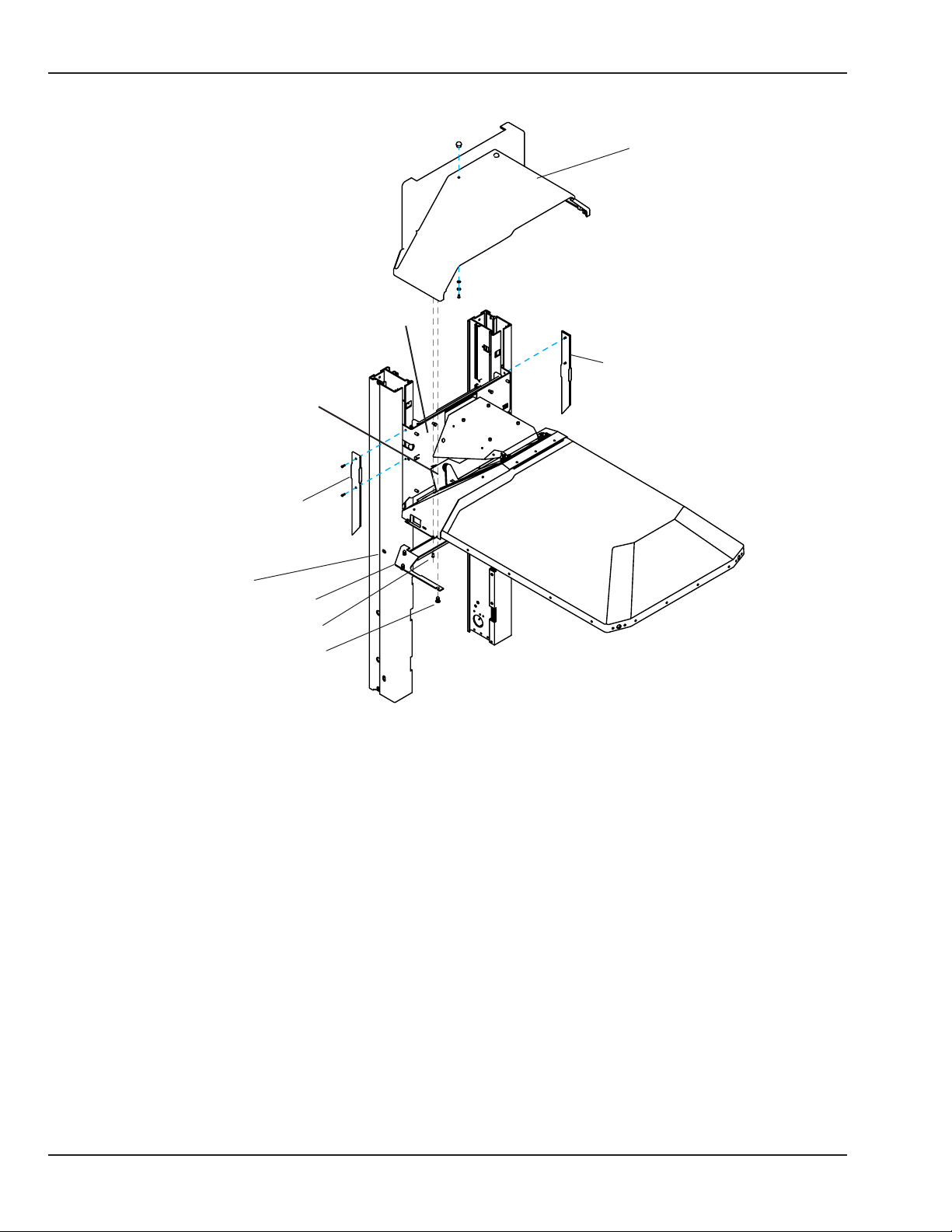
Chapter 5: Repair Procedures
Heater door bracket
Heater housing cover
Canopy bracket
Right inside cover
Left inside cover
Intermediate
oblong locking hole
Sot
Housing cover screw
Arrow clip
Canopy
Figure 5-1 Heater Housing Cover and Sot
b. Using a 2.5 mm hex key, remove the four screws that secure the heater housing cover to the heater
door bracket. Remove the heater housing cover. Save the four screws and heater housing cover for
later reinstallation.
72 6600-0343-000 104 © 2001 by Datex-Ohmeda, Inc.. All rights reserved.
 Loading...