

Page 1
Engström Ventilator
Technical Reference Manual
Page 2

Engström Ventilator
Datex-Ohmeda products have unit serial numbers with coded logic which indicates a product
group code, the year of manufacture, and a sequential unit number for identification. The serial
number can be in one of two formats.
AAAX11111 AA AXX111111A A
The X represents an alpha character
indicating the year the product was
manufactured; J = 2004, K = 2005, etc.
IIII and O are not used.
The XX represents a number indicating
the year the product was manufactured;
04
= 2004, 05 = 2005, etc.
Engström Ventilator, ComWheel, D-fend and
EVair 03 are registered trademarks of
Datex-Ohmeda Inc.
Other brand names or product names used in this manual are trademarks or registered
trademarks of their respective holders.
10/04 1505-1018-000
Page 3

Technical Reference Manual
Engström Ventilator
This document is not to be reproduced in any manner, nor are the contents to be disclosed to
anyone, without the express authorization of the product service department, Datex-Ohmeda,
Ohmeda Drive, PO Box 7550, Madison, Wisconsin, 53707.
©
2004 Datex-Ohmeda Inc.
1505-1018-000 10/04
i
Page 4

Engström Ventilator
Important
The information contained in this Technical Reference manual pertains only to those models of
products which are marketed by Datex-Ohmeda as of the effective date of this manual or the
latest revision thereof. This Technical Reference manual was prepared for exclusive use by
Datex-Ohmeda service personnel in light of their training and experience as well as the
availability to them of parts, proper tools and test equipment. Consequently, Datex-Ohmeda
provides this Technical Reference manual to its customers purely as a business convenience
and for the customer's general information only without warranty of the results with respect to
any application of such information. Furthermore, because of the wide variety of circumstances
under which maintenance and repair activities may be performed and the unique nature of each
individual's own experience, capacity, and qualifications, the fact that customer has received
such information from Datex-Ohmeda does not imply in anyway that Datex-Ohmeda deems said
individual to be qualified to perform any such maintenance or repair service. Moreover, it should
not be assumed that every acceptable test and safety procedure or method, precaution, tool,
equipment or device is referred to within, or that abnormal or unusual circumstances, may not
warrant or suggest different or additional procedures or requirements.
This manual is subject to periodic review, update and revision. Customers are cautioned to
obtain and consult the latest revision before undertaking any service of the equipment.
Comments and suggestions on this manual are invited from our customers. Send your
comments and suggestions to the Manager of Technical Communications, Datex-Ohmeda,
Ohmeda Drive, PO Box 7550, Madison, Wisconsin 53707.
wwww CAUTION
Servicing of this product in accordance with this
be undertaken in the absence of proper tools, test equipment and the most recent
revision to this service manual which is clearly and thoroughly understood.
Technical Competence
The procedures described in this Technical Reference manual should be performed by trained
and authorized personnel only. Maintenance should only be undertaken by competent
individuals who have a general knowledge of and experience with devices of this nature. No
repairs should ever be undertaken or attempted by anyone not having such qualifications.
Datex-Ohmeda strongly recommends using only genuine replacement parts, manufactured or
sold by Datex-Ohmeda for all repair parts replacements.
Read completely through each step in every procedure before starting the procedure; any
exceptions may result in a failure to properly and safely complete the attempted procedure.
Technical Reference
manual should never
ii
10/04 1505-1018-000
Page 5

Table of Contents
Important . . . . . . . . . . . . . . . . . . . . . . . . . . . . . . . . . . . . . . . . . . . . . . . . . . . . . . . . . . . . . . . . . . . . . .ii
Technical Competence . . . . . . . . . . . . . . . . . . . . . . . . . . . . . . . . . . . . . . . . . . . . . . . . . . . . . . . . . . .ii
1 Introduction
1.1 What this manual includes . . . . . . . . . . . . . . . . . . . . . . . . . . . . . . . . . . . . . . . . . . . . . . . . . .1-2
1.2 User’s Reference manuals . . . . . . . . . . . . . . . . . . . . . . . . . . . . . . . . . . . . . . . . . . . . . . . . . . .1-2
1.2 Conventions used . . . . . . . . . . . . . . . . . . . . . . . . . . . . . . . . . . . . . . . . . . . . . . . . . . . . . . . . . .1-2
1.3 What is an Engström Ventilator? . . . . . . . . . . . . . . . . . . . . . . . . . . . . . . . . . . . . . . . . . . . . . .1-3
1.4 Ventilator overview . . . . . . . . . . . . . . . . . . . . . . . . . . . . . . . . . . . . . . . . . . . . . . . . . . . . . . . . .1-4
1.5 Display controls and indicators . . . . . . . . . . . . . . . . . . . . . . . . . . . . . . . . . . . . . . . . . . . . . . .1-6
1.6 Ventilator display . . . . . . . . . . . . . . . . . . . . . . . . . . . . . . . . . . . . . . . . . . . . . . . . . . . . . . . . . . .1-7
1.6.1 Using menus . . . . . . . . . . . . . . . . . . . . . . . . . . . . . . . . . . . . . . . . . . . . . . . . . . . . . . . .1-9
1.7 Symbols used in the manual or on the equipment . . . . . . . . . . . . . . . . . . . . . . . . . . . . . 1-10
1505-1018-000 10/04 1
Page 6

Engström Ventilator
2 Theory of Operation
3 Checkout Procedure
2.1 Pneumatic Operation . . . . . . . . . . . . . . . . . . . . . . . . . . . . . . . . . . . . . . . . . . . . . . . . . . . . . . .2-2
2.1.1 Inspiratory circuit . . . . . . . . . . . . . . . . . . . . . . . . . . . . . . . . . . . . . . . . . . . . . . . . . . . .2-2
2.1.2 Expiratory circuit . . . . . . . . . . . . . . . . . . . . . . . . . . . . . . . . . . . . . . . . . . . . . . . . . . . . .2-7
2.1.3 Associated circuits . . . . . . . . . . . . . . . . . . . . . . . . . . . . . . . . . . . . . . . . . . . . . . . . . . .2-8
2.1.4 Electronic micropump nebulizer . . . . . . . . . . . . . . . . . . . . . . . . . . . . . . . . . . . . . . . .2-8
2.2 Electrical Operation . . . . . . . . . . . . . . . . . . . . . . . . . . . . . . . . . . . . . . . . . . . . . . . . . . . . . . . . .2-9
2.2.1 Display Unit (DU) . . . . . . . . . . . . . . . . . . . . . . . . . . . . . . . . . . . . . . . . . . . . . . . . . . . .2-9
2.2.2 Communication channels . . . . . . . . . . . . . . . . . . . . . . . . . . . . . . . . . . . . . . . . . . . 2-10
2.2.3 Ventilator Control Board - VCB . . . . . . . . . . . . . . . . . . . . . . . . . . . . . . . . . . . . . . . 2-12
2.2.4 Ventilator Monitoring Board - VMB . . . . . . . . . . . . . . . . . . . . . . . . . . . . . . . . . . . . 2-14
2.2.5 Power Management Board – PMB . . . . . . . . . . . . . . . . . . . . . . . . . . . . . . . . . . . . 2-16
2.2.6 Other Electronic Items . . . . . . . . . . . . . . . . . . . . . . . . . . . . . . . . . . . . . . . . . . . . . . 2-16
2.2.7 Motherboard (backplane) . . . . . . . . . . . . . . . . . . . . . . . . . . . . . . . . . . . . . . . . . . . 2-17
2.2.8 Monitoring Interface Board – Monitoring Module Bays . . . . . . . . . . . . . . . . . . . . 2-17
3.1 Inspect the system . . . . . . . . . . . . . . . . . . . . . . . . . . . . . . . . . . . . . . . . . . . . . . . . . . . . . . . . .3-2
3.2 Automated Checkout . . . . . . . . . . . . . . . . . . . . . . . . . . . . . . . . . . . . . . . . . . . . . . . . . . . . . . .3-2
3.3 Backlight test . . . . . . . . . . . . . . . . . . . . . . . . . . . . . . . . . . . . . . . . . . . . . . . . . . . . . . . . . . . . . .3-3
3.4 Power failure test . . . . . . . . . . . . . . . . . . . . . . . . . . . . . . . . . . . . . . . . . . . . . . . . . . . . . . . . . . .3-3
3.5 Electrical safety tests . . . . . . . . . . . . . . . . . . . . . . . . . . . . . . . . . . . . . . . . . . . . . . . . . . . . . . .3-3
4 Installation and Service Menus
4.1 Service and Installation menu structure . . . . . . . . . . . . . . . . . . . . . . . . . . . . . . . . . . . . . . . .4-2
4.2 Install/Service Menu (Super User) . . . . . . . . . . . . . . . . . . . . . . . . . . . . . . . . . . . . . . . . . . . . .4-3
4.2.1 Defaults . . . . . . . . . . . . . . . . . . . . . . . . . . . . . . . . . . . . . . . . . . . . . . . . . . . . . . . . . . . .4-4
4.2.2 Factory Defaults . . . . . . . . . . . . . . . . . . . . . . . . . . . . . . . . . . . . . . . . . . . . . . . . . . . . .4-5
4.3 Calibration menu . . . . . . . . . . . . . . . . . . . . . . . . . . . . . . . . . . . . . . . . . . . . . . . . . . . . . . . . . . .4-6
4.4 Service menu . . . . . . . . . . . . . . . . . . . . . . . . . . . . . . . . . . . . . . . . . . . . . . . . . . . . . . . . . . . . . .4-7
4.4.1 Configuration . . . . . . . . . . . . . . . . . . . . . . . . . . . . . . . . . . . . . . . . . . . . . . . . . . . . . . .4-8
4.4.2 Copy Configuration . . . . . . . . . . . . . . . . . . . . . . . . . . . . . . . . . . . . . . . . . . . . . . . . . . .4-9
4.4.3 Service Log menu . . . . . . . . . . . . . . . . . . . . . . . . . . . . . . . . . . . . . . . . . . . . . . . . . . 4-10
4.4.4 Software/Hardware version menu . . . . . . . . . . . . . . . . . . . . . . . . . . . . . . . . . . . . 4-11
2 10/04 1505-1018-000
Page 7

5 Service Tests and Calibration
5.1 Calibration (super-user) . . . . . . . . . . . . . . . . . . . . . . . . . . . . . . . . . . . . . . . . . . . . . . . . . . . . .5-2
5.2 Service level tests and calibration . . . . . . . . . . . . . . . . . . . . . . . . . . . . . . . . . . . . . . . . . . . . .5-4
Table of Contents
5.1.1 Calibration procedure . . . . . . . . . . . . . . . . . . . . . . . . . . . . . . . . . . . . . . . . . . . . . . . .5-3
5.2.1 Service application setup . . . . . . . . . . . . . . . . . . . . . . . . . . . . . . . . . . . . . . . . . . . . .5-4
5.2.2 Test setup . . . . . . . . . . . . . . . . . . . . . . . . . . . . . . . . . . . . . . . . . . . . . . . . . . . . . . . . . .5-4
5.2.3 Vent engine debris clean-out . . . . . . . . . . . . . . . . . . . . . . . . . . . . . . . . . . . . . . . . . . .5-5
5.2.4 Vent engine leak test (low pressure) . . . . . . . . . . . . . . . . . . . . . . . . . . . . . . . . . . . . .5-6
5.2.5 Vent engine leak test (high O2 pressure) . . . . . . . . . . . . . . . . . . . . . . . . . . . . . . . . .5-8
5.2.6 Vent engine leak test (high Air pressure) . . . . . . . . . . . . . . . . . . . . . . . . . . . . . . . . 5-10
5.2.7 Calibrate airway pressure transducer Zero and Span . . . . . . . . . . . . . . . . . . . . . 5-12
5.2.8 Verify operation of free- breathing valve . . . . . . . . . . . . . . . . . . . . . . . . . . . . . . . . 5-14
5.2.9 Verify operation of inspiratory effort valve . . . . . . . . . . . . . . . . . . . . . . . . . . . . . . 5-16
5.2.10 Verify operation of auxiliary pressure relief valve . . . . . . . . . . . . . . . . . . . . . . . . 5-18
5.2.11 Mechanical over-pressure valve test . . . . . . . . . . . . . . . . . . . . . . . . . . . . . . . . . 5-20
5.2.12 Verify regulator output pressure. . . . . . . . . . . . . . . . . . . . . . . . . . . . . . . . . . . . . . 5-22
6 Maintenance
7 Troubleshooting
6.1 Engström Ventilator planned maintenance . . . . . . . . . . . . . . . . . . . . . . . . . . . . . . . . . . . . . .6-2
6.1.1 Every twelve (12) months . . . . . . . . . . . . . . . . . . . . . . . . . . . . . . . . . . . . . . . . . . . . . .6-2
6.1.2 Every forty-eight (48) months . . . . . . . . . . . . . . . . . . . . . . . . . . . . . . . . . . . . . . . . . .6-2
6.2 Battery capacity test . . . . . . . . . . . . . . . . . . . . . . . . . . . . . . . . . . . . . . . . . . . . . . . . . . . . . . . .6-3
7.1 Troubleshooting Checkout Failures . . . . . . . . . . . . . . . . . . . . . . . . . . . . . . . . . . . . . . . . . . . .7-2
7.1.1 Paw Transducer Check . . . . . . . . . . . . . . . . . . . . . . . . . . . . . . . . . . . . . . . . . . . . . . . .7-2
7.1.2 Barometric pressure test . . . . . . . . . . . . . . . . . . . . . . . . . . . . . . . . . . . . . . . . . . . . . .7-2
7.1.3 Low Pressure Leak and Compliance Check . . . . . . . . . . . . . . . . . . . . . . . . . . . . . . .7-3
7.1.4 Safety Valve Relief and Back Pressure . . . . . . . . . . . . . . . . . . . . . . . . . . . . . . . . . . .7-3
7.1.5 Exhalation Valve Calibration Check . . . . . . . . . . . . . . . . . . . . . . . . . . . . . . . . . . . . . .7-4
7.1.6 Exhalation Flow Sensor Calibration Test . . . . . . . . . . . . . . . . . . . . . . . . . . . . . . . . . .7-4
7.1.7 Measure Breathing Circuit Resistance . . . . . . . . . . . . . . . . . . . . . . . . . . . . . . . . . . .7-4
7.1.8 Air Inspiratory Flow Sensor Calibration Check . . . . . . . . . . . . . . . . . . . . . . . . . . . . .7-5
7.1.9 O2 Inspiratory Flow Sensor Calibration Check . . . . . . . . . . . . . . . . . . . . . . . . . . . . .7-5
7.1.10 O2 Sensor Test and Calibration . . . . . . . . . . . . . . . . . . . . . . . . . . . . . . . . . . . . . . . .7-5
7.2 Troubleshooting Vent Engine Leaks . . . . . . . . . . . . . . . . . . . . . . . . . . . . . . . . . . . . . . . . . . . .7-6
7.3 Alarm message troubleshooting chart . . . . . . . . . . . . . . . . . . . . . . . . . . . . . . . . . . . . . . . . 7-10
7.4 Troubleshooting Service App messages . . . . . . . . . . . . . . . . . . . . . . . . . . . . . . . . . . . . . . 7-26
1505-1018-000 10/04 3
Page 8

Engström Ventilator
8 Service Diagnostics and Software Download
8.1 EV Service Application . . . . . . . . . . . . . . . . . . . . . . . . . . . . . . . . . . . . . . . . . . . . . . . . . . . . . .8-2
8.1.1 Main Menu and System Information . . . . . . . . . . . . . . . . . . . . . . . . . . . . . . . . . . . . .8-2
8.1.2 Power Diagnostics . . . . . . . . . . . . . . . . . . . . . . . . . . . . . . . . . . . . . . . . . . . . . . . . . . .8-3
8.1.3 Power Controller Power Diagnostics . . . . . . . . . . . . . . . . . . . . . . . . . . . . . . . . . . . . .8-4
8.1.4 Display Unit Power Diagnostics . . . . . . . . . . . . . . . . . . . . . . . . . . . . . . . . . . . . . . . . .8-6
8.2 Display Diagnostics . . . . . . . . . . . . . . . . . . . . . . . . . . . . . . . . . . . . . . . . . . . . . . . . . . . . . . . . .8-7
8.3 Special Functions . . . . . . . . . . . . . . . . . . . . . . . . . . . . . . . . . . . . . . . . . . . . . . . . . . . . . . . . . .8-8
8.3.1 View Revision Log . . . . . . . . . . . . . . . . . . . . . . . . . . . . . . . . . . . . . . . . . . . . . . . . . . . .8-9
8.3.2 View PC Card Install Log . . . . . . . . . . . . . . . . . . . . . . . . . . . . . . . . . . . . . . . . . . . . . . .8-9
8.4 Software Download . . . . . . . . . . . . . . . . . . . . . . . . . . . . . . . . . . . . . . . . . . . . . . . . . . . . . . . 8-10
8.5 EV Service Application (PC based) . . . . . . . . . . . . . . . . . . . . . . . . . . . . . . . . . . . . . . . . . . . 8-12
8.5.1 Port Setup . . . . . . . . . . . . . . . . . . . . . . . . . . . . . . . . . . . . . . . . . . . . . . . . . . . . . . . . 8-12
8.5.2 Main Menu and System Information . . . . . . . . . . . . . . . . . . . . . . . . . . . . . . . . . . . 8-12
8.6 VCB Diagnostics and Calibration . . . . . . . . . . . . . . . . . . . . . . . . . . . . . . . . . . . . . . . . . . . . 8-13
8.6.1 Sensirion Sensors . . . . . . . . . . . . . . . . . . . . . . . . . . . . . . . . . . . . . . . . . . . . . . . . . . 8-13
8.6.2 VCB Input Signal Latch . . . . . . . . . . . . . . . . . . . . . . . . . . . . . . . . . . . . . . . . . . . . . . 8-14
8.6.3 VCB Channel Configurations . . . . . . . . . . . . . . . . . . . . . . . . . . . . . . . . . . . . . . . . . 8-15
8.6.4 VCB Outputs . . . . . . . . . . . . . . . . . . . . . . . . . . . . . . . . . . . . . . . . . . . . . . . . . . . . . . 8-16
8.6.5 Calibrations and Tests . . . . . . . . . . . . . . . . . . . . . . . . . . . . . . . . . . . . . . . . . . . . . . 8-17
8.7 VMB Diagnostics . . . . . . . . . . . . . . . . . . . . . . . . . . . . . . . . . . . . . . . . . . . . . . . . . . . . . . . . . 8-18
9 Repair Procedures
8.7.1 VMB Channel Configurations . . . . . . . . . . . . . . . . . . . . . . . . . . . . . . . . . . . . . . . . . 8-19
8.7.2 VMB Outputs . . . . . . . . . . . . . . . . . . . . . . . . . . . . . . . . . . . . . . . . . . . . . . . . . . . . . 8-20
8.7.3 VMB Data . . . . . . . . . . . . . . . . . . . . . . . . . . . . . . . . . . . . . . . . . . . . . . . . . . . . . . . . 8-20
8.7.4 Baro P Cal . . . . . . . . . . . . . . . . . . . . . . . . . . . . . . . . . . . . . . . . . . . . . . . . . . . . . . . . 8-20
9.1 Circuit Board Replacement precautions . . . . . . . . . . . . . . . . . . . . . . . . . . . . . . . . . . . . . . . .9-3
9.1.1 Software download . . . . . . . . . . . . . . . . . . . . . . . . . . . . . . . . . . . . . . . . . . . . . . . . . . .9-3
9.1.2 Required calibrations . . . . . . . . . . . . . . . . . . . . . . . . . . . . . . . . . . . . . . . . . . . . . . . . .9-3
9.2 How to bleed gas pressure from the machine . . . . . . . . . . . . . . . . . . . . . . . . . . . . . . . . . . . .9-4
9.3 Accessing chassis components . . . . . . . . . . . . . . . . . . . . . . . . . . . . . . . . . . . . . . . . . . . . . . .9-4
9.3.1 To remove the chassis from the housing . . . . . . . . . . . . . . . . . . . . . . . . . . . . . . . . . .9-5
9.3.2 To remove the Vent Engine from the chassis . . . . . . . . . . . . . . . . . . . . . . . . . . . . . .9-5
9.3.3 To replace chassis mounted components . . . . . . . . . . . . . . . . . . . . . . . . . . . . . . . .9-6
9.3.4 To replace Vent Engine components . . . . . . . . . . . . . . . . . . . . . . . . . . . . . . . . . . . . .9-6
4 10/04 1505-1018-000
Page 9

10 Illustrated Parts
Engström Ventilator
9.4 Servicing the Display Unit . . . . . . . . . . . . . . . . . . . . . . . . . . . . . . . . . . . . . . . . . . . . . . . . . . . .9-7
9.4.1 Remove the Display Unit . . . . . . . . . . . . . . . . . . . . . . . . . . . . . . . . . . . . . . . . . . . . . .9-7
9.4.2 Disassemble the Display Unit . . . . . . . . . . . . . . . . . . . . . . . . . . . . . . . . . . . . . . . . . .9-8
9.4.3 To replace the CPU board . . . . . . . . . . . . . . . . . . . . . . . . . . . . . . . . . . . . . . . . . . . . .9-9
9.4.4 To replace the LCD display . . . . . . . . . . . . . . . . . . . . . . . . . . . . . . . . . . . . . . . . . . . 9-10
9.4.5 To replace the backlights . . . . . . . . . . . . . . . . . . . . . . . . . . . . . . . . . . . . . . . . . . . . 9-11
9.4.6 To replace the Inverters . . . . . . . . . . . . . . . . . . . . . . . . . . . . . . . . . . . . . . . . . . . . . 9-12
9.4.7 To replace the front enclosure or components . . . . . . . . . . . . . . . . . . . . . . . . . . . 9-13
9.5 Adjusting the display arm . . . . . . . . . . . . . . . . . . . . . . . . . . . . . . . . . . . . . . . . . . . . . . . . . . 9-15
9.5.1 Adjust upper pivot . . . . . . . . . . . . . . . . . . . . . . . . . . . . . . . . . . . . . . . . . . . . . . . . . 9-15
9.5.2 Adjust lower pivot . . . . . . . . . . . . . . . . . . . . . . . . . . . . . . . . . . . . . . . . . . . . . . . . . . 9-16
9.5.3 Adjust arm bearing . . . . . . . . . . . . . . . . . . . . . . . . . . . . . . . . . . . . . . . . . . . . . . . . . 9-16
9.6 Removing a compressor from the cart . . . . . . . . . . . . . . . . . . . . . . . . . . . . . . . . . . . . . . . . 9-17
10.1 Service tools . . . . . . . . . . . . . . . . . . . . . . . . . . . . . . . . . . . . . . . . . . . . . . . . . . . . . . . . . . . 10-2
10.1.1 Software tools . . . . . . . . . . . . . . . . . . . . . . . . . . . . . . . . . . . . . . . . . . . . . . . . . . . . 10-2
10.1.2 Manual shut-off valves . . . . . . . . . . . . . . . . . . . . . . . . . . . . . . . . . . . . . . . . . . . . . 10-3
10.1.3 Special tools . . . . . . . . . . . . . . . . . . . . . . . . . . . . . . . . . . . . . . . . . . . . . . . . . . . . . 10-3
10.1.4 Leak test devices. . . . . . . . . . . . . . . . . . . . . . . . . . . . . . . . . . . . . . . . . . . . . . . . . . 10-4
10.1.5 Lubricants and Adhesives . . . . . . . . . . . . . . . . . . . . . . . . . . . . . . . . . . . . . . . . . . 10-5
10.2 External components - front view . . . . . . . . . . . . . . . . . . . . . . . . . . . . . . . . . . . . . . . . . . . 10-6
Schematics and Diagrams
10.3 External components - rear view . . . . . . . . . . . . . . . . . . . . . . . . . . . . . . . . . . . . . . . . . . . 10-7
10.4 Display arm mounting hardware . . . . . . . . . . . . . . . . . . . . . . . . . . . . . . . . . . . . . . . . . . . 10-8
10.5 Display arm assembly . . . . . . . . . . . . . . . . . . . . . . . . . . . . . . . . . . . . . . . . . . . . . . . . . . 10-10
10.6 Display Unit . . . . . . . . . . . . . . . . . . . . . . . . . . . . . . . . . . . . . . . . . . . . . . . . . . . . . . . . . . . 10-12
10.7 Main enclosure (external) . . . . . . . . . . . . . . . . . . . . . . . . . . . . . . . . . . . . . . . . . . . . . . . . 10-14
10.8 Main enclosure (internal) . . . . . . . . . . . . . . . . . . . . . . . . . . . . . . . . . . . . . . . . . . . . . . . . 10-16
10.9 Vent Engine . . . . . . . . . . . . . . . . . . . . . . . . . . . . . . . . . . . . . . . . . . . . . . . . . . . . . . . . . . . 10-18
10.10 Outlet manifold . . . . . . . . . . . . . . . . . . . . . . . . . . . . . . . . . . . . . . . . . . . . . . . . . . . . . . . 10-20
10.11 Inlet manifold . . . . . . . . . . . . . . . . . . . . . . . . . . . . . . . . . . . . . . . . . . . . . . . . . . . . . . . . 10-22
10.12 AC power cords . . . . . . . . . . . . . . . . . . . . . . . . . . . . . . . . . . . . . . . . . . . . . . . . . . . . . . . 10-23
10.13 AC Inlet/Outlet Components . . . . . . . . . . . . . . . . . . . . . . . . . . . . . . . . . . . . . . . . . . . . 10-24
10.14 Cart . . . . . . . . . . . . . . . . . . . . . . . . . . . . . . . . . . . . . . . . . . . . . . . . . . . . . . . . . . . . . . . . 10-26
10.15 Module rack . . . . . . . . . . . . . . . . . . . . . . . . . . . . . . . . . . . . . . . . . . . . . . . . . . . . . . . . . 10-28
10.16 Compressor . . . . . . . . . . . . . . . . . . . . . . . . . . . . . . . . . . . . . . . . . . . . . . . . . . . . . . . . . . 10-29
10.16 Exhalation valve assembly . . . . . . . . . . . . . . . . . . . . . . . . . . . . . . . . . . . . . . . . . . . . . . 10-30
1505-1018-000 10/04 5
Page 10

Notes
6 10/04 1505-1018-000
Page 11

1 Introduction
In this section
This section provides a general overview of the Engström Ventilator.
1.1 What this manual includes . . . . . . . . . . . . . . . . . . . . . . . . . . . . . . . . . . . . . . . . . . . . . . . . . . .1-2
1.2 User’s Reference manuals . . . . . . . . . . . . . . . . . . . . . . . . . . . . . . . . . . . . . . . . . . . . . . . . . . .1-2
1.2 Conventions used . . . . . . . . . . . . . . . . . . . . . . . . . . . . . . . . . . . . . . . . . . . . . . . . . . . . . . . . . .1-2
1.3 What is an Engström Ventilator? . . . . . . . . . . . . . . . . . . . . . . . . . . . . . . . . . . . . . . . . . . . . . .1-3
1.4 Ventilator overview . . . . . . . . . . . . . . . . . . . . . . . . . . . . . . . . . . . . . . . . . . . . . . . . . . . . . . . . .1-4
1.5 Display controls and indicators . . . . . . . . . . . . . . . . . . . . . . . . . . . . . . . . . . . . . . . . . . . . . . .1-6
1.6 Ventilator display . . . . . . . . . . . . . . . . . . . . . . . . . . . . . . . . . . . . . . . . . . . . . . . . . . . . . . . . . . .1-7
1.6.1 Using menus . . . . . . . . . . . . . . . . . . . . . . . . . . . . . . . . . . . . . . . . . . . . . . . . . . . . . . . .1-9
1.7 Symbols used in the manual or on the equipment . . . . . . . . . . . . . . . . . . . . . . . . . . . . . . 1-10
1505-1018-000 10/04 1-1
Page 12

Engström Ventilator
1.1 What this manual includes
This manual covers the service information for the Engström Ventilator.
It covers the following components:
• Display Unit
• Integral electronics
• Gas delivery components
• Frame component
Other equipment
Other equipment may be attached to the system. Consult separate
documentation relative to these items for details.
1.2 User’s Reference manuals
Some sections of this manual refer you to the User’s Reference manual for the
Engström Ventilator. To expedite repairs, you must have, and be familiar with,
the User’s Reference manual for this product.
Refer to the Engström Ventilator User’s Reference manual if you need further
information about the operation of the system.
Conventions used
Hard keys
Menu selections
Names of the hard keys on the display and modules are written in bold
typeface, for example,
Menu selections are written in bold italic typeface, for example,
Setup
.
Normal Screen
.
Patient
Messages
Sections and headings
1-2 10/04 1505-1018-000
Messages that are displayed on the screen are enclosed in single quotes, for
example, ‘Check sample gas out.’
When referring to different sections or headings in the User’s Reference
manual, the name is written in italic typeface and is enclosed in double
quotes, for example,
“System Controls and Menus.”
Page 13

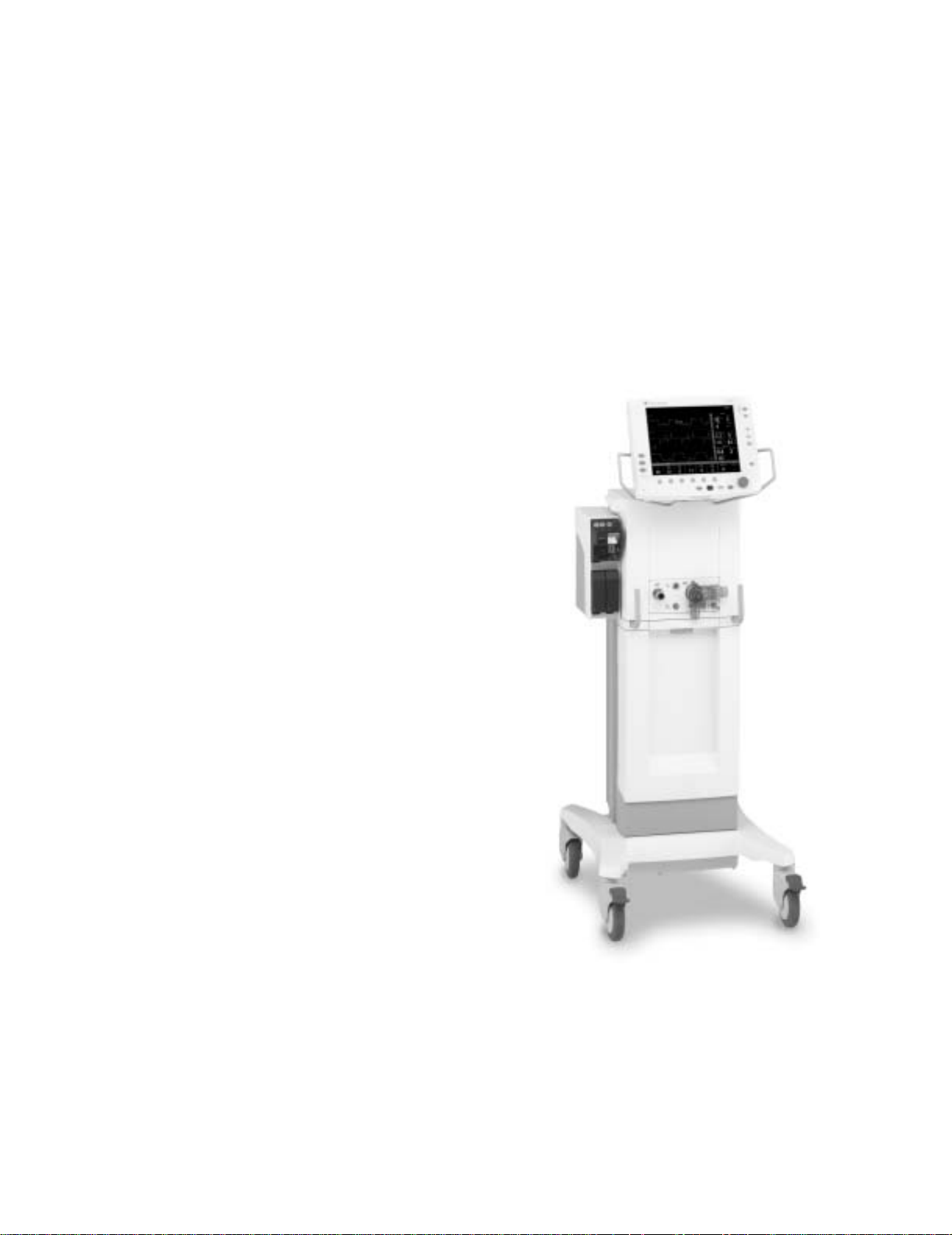
1.3 What is an Engström Ventilator?
The Engström Ventilator (EV) is a flexible, adaptable, and intuitive critical care
ventilator. A wide selection of performance options gives the user full control
of the system configuration.
The EV must only be operated by authorized medical personnel well trained in
the use of this product, for patient ventilation in the intensive care
environment. It must be operated according to the instructions in this User’s
Reference manual.
The ventilator is designed to be used with infant through adult patients with a
body weight of 5 kg or greater. The EV is designed to maintain lung ventilation
in the absence of spontaneous breathing effort as well as in support of the
patient’s existing spontaneous breathing effort.
The system is designed for facility use, including within-facility transport.
The ventilator consists of three main components: a display, a ventilator unit,
and an optional module bay. The display allows the user to interface with the
system and control settings. The ventilator unit controls electrical power,
nebulization, and pneumatic gas flow to and from the patient. The module bay
allows the integration of various patient monitoring modules with the
ventilator.
1 Introduction
Optional accessories include an air compressor, airway modules, module
bay, humidifier and water trap mounting brackets, and auxiliary electrical
outlets.
Figure 1-1 • Engström Ventilator (EV)
1505-1018-000 10/04 1-3
Page 14

Engström Ventilator
1.4 Ventilator overview
7
6
5
1
891011
2
3
12
13
AB.98.011
4
1. Module bay (optional)
2. Ventilator lock [locks Ventilator unit (item 6) to Cart (item 3)]
3. Cart
4. Caster
5. Dovetail rails
6. Ventilator unit
7. Display
8. Nebulizer connection
9. Exhalation valve housing
10. Expiratory inlet
11. Expiratory flow sensor
12. Gas exhaust port
13. Leak test plug
14. Exhalation valve housing latch
15. Water trap
16. Auxiliary pressure port
17. Inspiratory outlet
AB.98.007
1617
1415
Figure 1-2 • Front view of the EV
1-4 10/04 1505-1018-000
Page 15
15
14
13
1 Introduction
1
2
3
19
12
4
18
5
3
11
6
2
10
7
9
8
AB.98.009
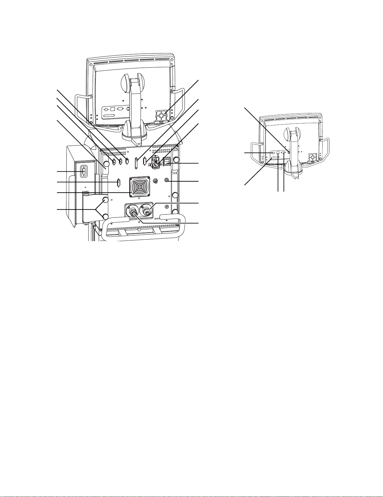
1. Display fan filter
2. Display connection
3. Module bay connection
4. AC mains inlet
5. System switch
6. Equipotential connector
7. Oxygen supply connection (pipeline)
8. Air supply connection (pipeline or compressor)
9. Module bay mounting thumbscrews
10. Ventilator unit fan filter
11. Serial communication port (RS 232 port)
12. Arm holder
13. RS 485 port (not currently supported)
14. RS 485 port (not currently supported)
15. RS 422 port (used to communicate with PC based Service Application — Refer to Section 8.5)
16. Network ID connection
17. Ethernet connection
18. DIS port (not currently supported)
19. USB port
AB.98.045
1617
Figure 1-3 • Back view of the E V
1505-1018-000 10/04 1-5
Page 16

Engström Ventilator
1.5 Display controls and indicators
8
3
1
2
3
7
6
3
1 Alarm LEDs The red and yellow LEDs indicate the priority of active alarms.
2 Alarm Silence key Push to silence any active, silenceable high and medium priority alarms or
to suspend any non-active medium priority alarms. Alarm audio is silenced
or suspended for 120 seconds. Push to clear resolved alarms.
3 Menu keys Push to show corresponding menu.
4 ComWheel Push to select a menu item or confirm a setting. Turn clockwise or
counterclockwise to scroll menu items or change settings.
5 Normal Screen key Push to remove all menus from the screen.
6AC mains indicator The green LED lights continuously when the EV is connected to an AC mains
source. The internal batteries are charging when the LED is lit.
7 Quick keys Push to change corresponding ventilator setting. Turn the ComWheel to
make a change. Push the Quick key or ComWheel to activate the change.
8100% O2 key Push to deliver 100% O
for 2 minutes.
2
5
4
AB.98.012
Figure 1-4 • Controls and indicators
1-6 10/04 1505-1018-000
Page 17
1.6 Ventilator display
1 Introduction
12 34
•
5
6
AB.98.013
8
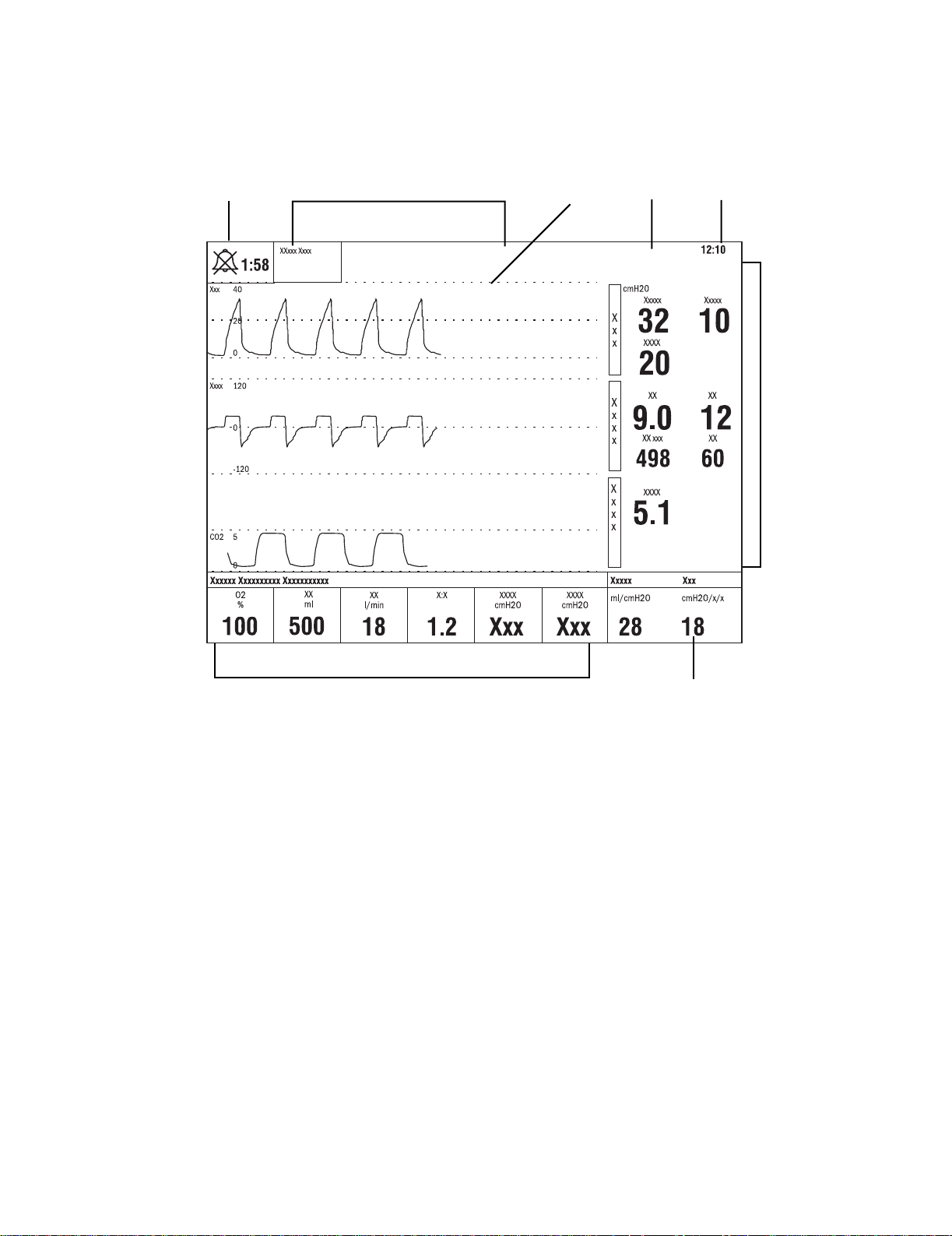
1 Alarm silence symbol
and countdown
2 Alarm message fields Alarms will appear in order of priority. Refer to
3Waveform fields The top two waveforms are permanently set to Paw and Flow. The third waveform may be selected
4 General message field Displays informational messages.
5 Clock The time may be set in 12 or 24 hour format in the Time and Date menu.
6 Measured value fields Displays current measured values corresponding to the waveforms.
7 Digit field Displays information related to Volume, CO2, O2, Compliance or Spirometry.
8Ventilator settings Displays several of the settings for the current mode of ventilation.
Displays the time remaining during an alarm silence or alarm suspend period.
“Alarms and Troubleshooting”
on alarm behavior.
as CO2, O2, Vol, Paux, or Off.
7
for more information
Figure 1-5 • Normal Screen view
1505-1018-000 10/04 1-7
Page 18
Engström Ventilator
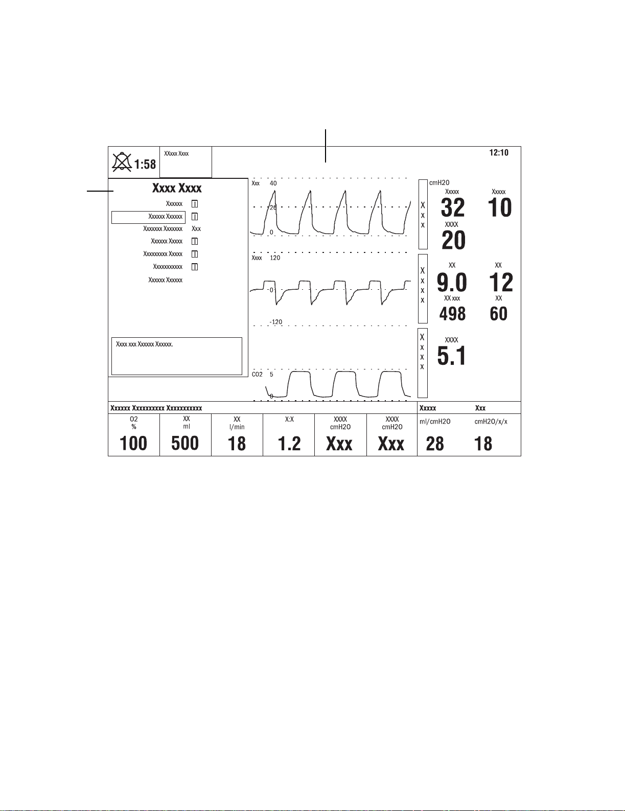
1
When a menu key is selected the waveform fields start at the right edge of the
menu. The entire waveform is always displayed.
2
1. Menu
2. Waveform fields
Figure 1-6 • Menu view
1-8 10/04 1505-1018-000
AB.98.014
Page 19

1 Introduction
1.6.1 Using menus
Push a menu key to display the corresponding menu. Use the ComWheel to
navigate through the menu.
1
2
3
6
4
Xxxxxx Xxxxxx
5
AB.91.007
1. Menu title
2. Present selection
3. Adjustment window
4. Indicates submenu
5. Short instructions
6. Menu selections
Figure 1-7 • Example menu
1. Push the menu key to display the corresponding menu.
2. Turn the ComWheel counterclockwise to highlight the next menu item.
(Turn the ComWheel clockwise to highlight the previous menu item.)
3. Push the ComWheel to enter the adjustment window or a submenu.
4. Turn the ComWheel clockwise or counterclockwise to highlight the
desired selection.
5. Push the ComWheel to confirm the selection.
6. Select
Normal Screen
or push the
Normal Screen
and return to the normal monitoring display. (Select
key to exit the menu
Previous Menu
to
return to the last displayed menu, if available.)
1505-1018-000 10/04 1-9
Page 20

Engström Ventilator
1.7 Symbols used in the manual or on the equipment
Symbols replace words on the equipment, on the display, or in
Datex-Ohmeda manuals.
Warnings and Cautions tell about the dangerous conditions that can occur if
the instructions in the manual are not followed.
Warnings tell about a condition that can cause injury to the operator or the
patient.
Cautions tell about a condition that can cause damage to the equipment.
Read and follow all warnings and cautions.
l
p
o
wW
REF
†
y
Y
z
t
On (power)
Off (power)
O
On for part of the equipment
Off for part of the equipment
œ
Standby
Attention, refer to product instructions
IEC 60601-1
Stock number
Direct current
m
w
SN
Type B protection against
electrical shock
Caution, ISO 7000-0434
Serial number
Alternating current
∏
Earth ground
Protective earth ground
x
Equipotential connector Fuse
Lock
Unlock
Z
Variability
Variability in steps
T
+
N
N
N
1-10 10/04 1505-1018-000
Plus, positive polarity
-
Movement in one direction
ˆ
This way up Warning, dangerous voltage
Minus, negative polarity
Movement in both directions
Page 21

1 Introduction
Pneumatic inlet Pneumatic outlet
Electrical input Electrical output
Inspiratory port Expiratory port
Electrical testing certification Inspiratory breath identifier
Serial port Module data indicator
Module bay port Electronic micropump nebulizer
Auxiliary pressure port Display signal input/output
No battery/battery failure Battery in use. Bar indicates
amount of battery power
remaining.
Silence alarms Submenu
Hourmeter Drain outlet
1505-1018-000 10/04 1-11
Page 22
Engström Ventilator
Air Pump
Heavy object USB port
134°C
Ethernet connection Network ID connection
Autoclavable
ID
X1
(Datex-Ohmeda proprietary port)
Not autoclavable
Í
Authorized representative in the
European Community
XXXX
Systems with this mark agree with
the European Council Directive
(93/42/EEC) for Medical Devices
when they are used as specified in
their User’s Reference Manuals.
The xxxx is the certification number
of the Notified Body used by
Datex-Ohmeda’s Quality Systems.
1-12 10/04 1505-1018-000
Page 23

2 Theory of Operation
In this section
2.1 Pneumatic Operation . . . . . . . . . . . . . . . . . . . . . . . . . . . . . . . . . . . . . . . . . . . . . . . . . . . . . . .2-2
2.1.1 Inspiratory circuit . . . . . . . . . . . . . . . . . . . . . . . . . . . . . . . . . . . . . . . . . . . . . . . . . . . .2-2
2.1.2 Expiratory circuit . . . . . . . . . . . . . . . . . . . . . . . . . . . . . . . . . . . . . . . . . . . . . . . . . . . . .2-7
2.1.3 Associated circuits . . . . . . . . . . . . . . . . . . . . . . . . . . . . . . . . . . . . . . . . . . . . . . . . . . .2-8
2.1.4 Electronic micropump nebulizer . . . . . . . . . . . . . . . . . . . . . . . . . . . . . . . . . . . . . . . .2-8
2.2 Electrical Operation . . . . . . . . . . . . . . . . . . . . . . . . . . . . . . . . . . . . . . . . . . . . . . . . . . . . . . . . .2-9
2.2.1 Display Unit (DU) . . . . . . . . . . . . . . . . . . . . . . . . . . . . . . . . . . . . . . . . . . . . . . . . . . . .2-9
2.2.2 Communication channels . . . . . . . . . . . . . . . . . . . . . . . . . . . . . . . . . . . . . . . . . . . 2-10
2.2.3 Ventilator Control Board - VCB . . . . . . . . . . . . . . . . . . . . . . . . . . . . . . . . . . . . . . . 2-12
2.2.4 Ventilator Monitoring Board - VMB . . . . . . . . . . . . . . . . . . . . . . . . . . . . . . . . . . . . 2-14
2.2.5 Power Management Board – PMB . . . . . . . . . . . . . . . . . . . . . . . . . . . . . . . . . . . . 2-16
2.2.6 Other Electronic Items . . . . . . . . . . . . . . . . . . . . . . . . . . . . . . . . . . . . . . . . . . . . . . 2-16
2.2.7 Motherboard (backplane) . . . . . . . . . . . . . . . . . . . . . . . . . . . . . . . . . . . . . . . . . . . 2-17
2.2.8 Monitoring Interface Board – Monitoring Module Bays . . . . . . . . . . . . . . . . . . . . 2-17
1505-1018-000 10/04 2-1
Page 24
Engström Ventilator
2.1 Pneumatic Operation
For a complete diagram of the pneumatic system, refer to Figure 11-2, "
Engine manifold flow diagram
" in Section11.
Vent
The EV requires a medical-grade oxygen (O2) and Air source ranging from 2.4
to 6.5 bar (35 to 94 psi).
The system includes two separate channels (O2 and Air) to provide dynamic
mixture control of the delivered O2 percentage.
The Air supply may include an optional compressor unit {1} for applications
where pipeline Air is not available or to provide a continued Air supply if the
pipeline supply goes down.
Air
O2
2.1.1 Inspiratory circuit
{1}
Air
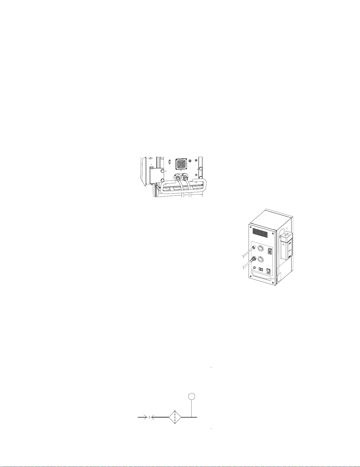
Compressed gas enters the EV through an inlet fitting {2} that is particular to
the institution’s supply system. The gas is filtered through a 2-micron
particulate filter {3} as it enters the ventilator’s “pneumatic engine” manifold.
A high-pressure transducer {4} having a dynamic range of 0 to 8.3 bar
(0 to 120 psi) is tapped at the outlet of the filter. This transducer monitors the
adequacy of the supply pressure. Failures of supply gas, coupling hoses or an
occluded filter are identified by the supply pressure transducer.
{4}
High Pressure
Transducer
{2}
Primary
Inlet
{3}
Inlet
Filter
P
Check
Valve
2-2 10/04 1505-1018-000
Page 25

2 Theory of Operation
Next in the downstream path of flow is a check valve {5}. The check valve
prevents backflow from the EV that would possibly contaminate the supply
pressure lines. For example; if the O
the O2 channel will prevent Air from moving back into the O2 supply lines.
High Pressure
Transducer
P
Primary
Inlet
Inlet
Filter
Check
Valv e
{5}
Downstream from the check valve is a 172 kPa (25 psi) pressure regulator {6}.
(The regulator is a non-relieving type that does not bleed gas into the
ventilator’s enclosure.) The regulator ensures a constant pressure supply to
the flow valve {8}. The regulated supply is flow rate dependant, which is
compensated for in the flow valve’s on-site calibration.
supply were to be lost, the check valve in
2
{8}
Flow
Valv e
Primary
Inlet
Inlet
Filter
High Pressure
Transducer
P
Check
Valv e
{6}
Regulator
25 psi
172 kPa
{7}
Flow
Test
Port
Sensor
H
T
Between the regulator and the flow valves is the inspiratory flow sensor {7}.
The sensor is a thermal mass-flow type that injects heat into the flow stream
and monitors the associated temperature rise at a downstream location. The
temperature change is dependent on the mass flow of the flow stream and
the specific heat of the gas moving through the sensor. Since the composition
of gas in the sensor is known, a conversion of mass-flow rate to volumetric
flow at ambient conditions can be made using the ambient density of the gas.
The sensor uses a laminar (two channel) flow element to split a portion of the
flow through the sensor past the heat injection and temperature sensing
elements. The sensor is pre-calibrated and includes an electronic PCB that
produces direct digital output of mass flow through an RS-232 interface.
Individual flow sensors measure the volume of gas dispensed from the O
and
2
Air channels during inspiration and expiration. The relative proportion of gas
dispensed from each channel is continuously adjusted to precisely control the
percentage of O2 delivered to the patient.
1505-1018-000 10/04 2-3
Page 26

Engström Ventilator
Downstream of the flow sensor is a flow valve {8} that meters flows from
approximately 0.05 l/min (leakage level) to a full flow value of 160 l/min. The
valve is a normally- closed proportional solenoid that is powered by a current
feedback loop. When calibrated on-site, using data from the inspiratory flow
sensor, a precise volumetric flow versus input current profile is developed that
includes both the valve and regulator characteristics.
{8}
Valv e
Flow
Primary
Inlet
Inlet
Filter
High Pressure
Transducer
P
Check
Valv e
Regulator
25 psi
172 kPa
Flow
Sensor
Test
Port
H
T
Following the two individual flow valves is the total flow sensor {10}. This
sensor is the same type as the individual flow sensors and is used to measure
the combined inspiratory flow being dispensed from the system. Using the
known mixture composition along with atmospheric pressure and gas
temperature information, mass-flow data from the sensor is converted to
delivered volumetric flow towards the patient. During calibration, the sensor is
checked against the output of the O
and Air flow sensors to ensure proper
2
operation.
Flow
Flow
Sensor
H
T
Flow
Sensor
H
T
Valv e
Flow
Valv e
Air
Pneumatic
Resistor
{10}
Tot al Flow
H
T
Inspiratory
Effort
Valv e
Free Breathing
O
2
Check Valve
2-4 10/04 1505-1018-000
Page 27

2 Theory of Operation
Following the total flow sensor are the free-breathing check valve {11} and the
inspiratory effort valve {12}.
During normal operation, the inspiratory effort valve is open, allowing the
free-breathing check valve to admit flow if the patient draws a significant
amount of inspiratory pressure, causing the airway pressure to become more
negative than -0.5 cm H
to spontaneously breathe in case of a ventilation delivery failure.
On occasion, to assess the patient’s tolerance to be weaned from the
ventilator, clinicians can determine the amplitude of inspiratory effort that the
patient can create. During this “procedure”, the inspiratory effort valve is
closed, effectively locking out the free breathing valve from the patient circuit.
Flow
Flow
Sensor
H
T
Valv e
O. The free-breathing check valve allows the patient
2
Pneumatic
Resistor
P
Expiratory Press
Air
Tot al Flow
H
T
Flow
Sensor
H
T
Flow
Valv e
Inspiratory
Effort
Valv e
{12}
Free Breathing
O
2
Check Valve
{11}
{13}
O2 Sensor
O
2
Auxil
Next in the flow path is the O2 sensor {13}. The sensor is used to monitor the
O2 concentration produced by the combined O2 and Air flows.
The O2 sensor uses the paramagnetic principle (oxygen molecules are
attracted in magnetic fields) to measure the oxygen concentration. The sensor
includes two nitrogen-filled glass spheres mounted on a suspension
containing a conductive coil that is located in a non-uniform magnetic field.
When the system is disturbed by an impulse of current, the suspension begins
to oscillate, inducing an EMF into the coil. The oscillation period of the
induced EMF is dependent on the partial pressure of oxygen surrounding the
suspension.
As sample gas fills the sensor, oxygen that is present in the sample is
attracted into the strongest part of the magnetic field. This congregation of O
molecules alters the natural oscillation frequency of the suspension.
Calculations based on the difference between the oscillation period for an
oxygen sample and that for nitrogen, and readings from the absolute pressure
transducer, determine the measured O
1505-1018-000 10/04 2-5
percentage.
2
2
Page 28
Engström Ventilator
n
Expirat
As a safety measure, a relief valve {14}, located downstream from the O2
sensor, can be energized to vent the full flow rate of the inspiratory delivery
side of the system. If an overpressure condition is detected, the valve can be
opened by either of the EV’s two control processors. To provide redundant
safety (independent of the electronic circuits), the valve begins to
mechanically relieve pressure at a nominal 115 cm H
Flow
Flow
Sensor
H
T
Valv e
Air
Pneumatic
Resistor
Tot al Flow
T
Expiratory Pressure
H
O2 Sensor
O.
2
ory Zero
Valv e
P
Exhalatio
Valv e
{15}
Inspiratory Pressure
P
Inspiratory Zero
Valv e
O
2
Flow
Sensor
H
T
Flow
Valv e
Inspiratory
Effort
Valv e
Safety
Free Breathing
O
2
Check Valve
Relief Valve
{14}
Auxiliary Pressure
Relief
The inspiratory airway pressure transducer {15}, along with its associated
zeroing valve, is located just prior to the inspiratory outlet port. This
transducer has a range of –20 to 120 cm H2O and serves as one of three
airway pressure measuring devices in the EV.
2-6 10/04 1505-1018-000
Page 29

2 Theory of Operation
2.1.2 Expiratory circuit At the expiratory side of the ventilator, a solenoid powered exhalation valve
{16} controls exhaust from the breathing circuit. The valve contains an
elastomer diaphragm that is held against a rigid seat by a solenoid (voice coil)
driven piston. The valve achieves a balance between the pressure generated
within its 21-mm diameter seat area and the force applied by the piston,
releasing exhalation flow as necessary to maintain balance. The proportional
solenoid controls the exhalation sealing pressure within a range of 0 to 100
cm H
O. Software control provides continuous oscillatory movement
2
(dithering) of the exhalation valve to minimize static friction effects.
{20}
H
30 mm Male Cone
Exhalation
Flow Sensor
{19}
EXP
22 / 15 mm
Male / Female
INSP
22 / 15 mm
Male / Female
From
Patient
To
Micropump
Nebulizer
Patient
Air
Pneumatic
Resistor
Tot al Flow
T
H
Inspiratory
Effort
Valv e
Pneumatic
Resistor
{18}
Expiratory Zero
P
Expiratory Pressure
Valv e
{16}
Exhalation
Valv e
{17}
Inspiratory Pressure
P
Inspiratory Zero
O2 Sensor
O
2
Safety
Valv e
Immediately upstream of the exhalation valve is a tap for the expiratory
pressure transducer {17} and its associated zeroing valve. The expiratory
pressure tap is continuously purged with 35 ml/min of air to ensure that
exhaled condensate does not occlude the tap. The air flow is established from
the regulated Air supply using a fixed orifice (pneumatic resistor) {18}.
Downstream of the exhalation valve is the expiratory flow transducer {19}. In
principle, the transducer is similar to a hot-wire anemometer. A wire having a
large “temperature to electrical resistance” relationship is placed in the
flowstream. The wire is kept at a constant temperature using a Wheatstone
bridge circuit. The current necessary to maintain the resistance of the sensor
portion of the bridge is a function of the flow through the sensor.
At the output of the flow sensor is a flapper type check valve {20} that
prevents gas from being drawn in through the expiratory valve and minimizes
patient rebreathing in the event of a ventilator failure.
1505-1018-000 10/04 2-7
Page 30

Engström Ventilator
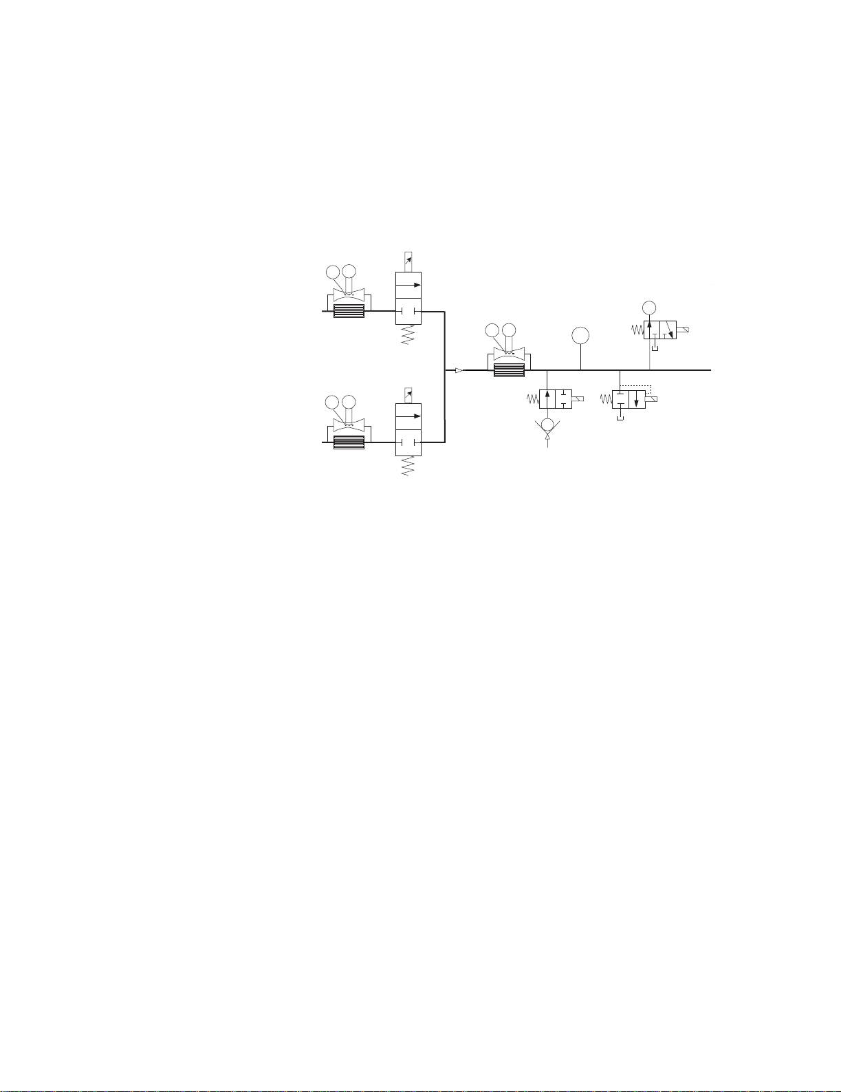
2.1.3 Associated circuits Associated with the inspiratory and expiratory pressure transducers are two
“zeroing” solenoid valves {21} and {22}. These valves are used to disconnect
the pressure transducers from circuit pressure and vent them to atmosphere
during zero bias calibration. This zeroing procedure is conducted routinely
(every 12 hours) under the control of the Vent Engine software.
Pneumatic
High Pressure
Transducer
P
Inlet
Filter
Primary
Inlet
Air
High Pressure
Transducer
Inlet
Filter
Primary
Inlet
O
2
Regulator
25 psi
172 kPa
Check
Valve
Regulator
25 psi
P
172 kPa
Check
Valve
Sensor
Test
Port
T
Sensor
Test
Port
T
Flow
Valve
Flow
H
Flow
Flow
Valve
H
{25}
Pneumatic
Resistor
T
Tota l Flow
Inspiratory
Effort
Valve
H
Free Breathing
Check Valve
Auxiliary Pressure
Resistor
{24}
Purge Valve
P
Expiratory Pressure
O2 Sensor
O
2
Auxiliary Pressure
Relief Valve
{23}
Transducer
P
{22}
Expiratory Zero
Valve
Inspiratory Pressure
Safety
P
{26}
{21}
Inspiratory Zero
Relief
Valve
Valve
Exhalation
Valve
30 mm Male Cone
Exhalation
Flow Sensor
H
EXP
22 / 15 mm
Male / Female
P
a
tie
n
t
INSP
22 / 15 mm
Male / Female
Micropump
Nebulizer
{27}
Paux
1/8,3/16, 1/4 inch Stepped Hose Barb
A third (auxiliary) pressure channel {23} is used to measure additional patient
“airway” pressures at the discretion of the clinician. This port could be used to
measure circuit pressure directly at the airway, laryngeal cuff pressures or
pressures lower in the airway tract. The transducer circuit includes a valve {24}
to provide a 35 ml/min purge flow as required by the particular clinical
application. For example, in measuring airway pressure at the endotracheal
tube the purge would most likely be turned on, but for measuring laryngeal
cuff pressures (closed system) the purge would be turned off. The purge flow
is established from the regulated Air supply using a fixed orifice (pneumatic
resistor) {25}. The relief valve {26} limits pressure in the auxiliary channel to
less than 230 cm H
O.
2
2.1.4 Electronic
micropump nebulizer
The Aeroneb Professional Nebulizer System (Aeroneb Pro) by Aerogen, Inc.
{27} is integrated into the EV. This nebulizer is electrically connected to the EV
and uses proprietary technology to produce a fine-droplet, low-velocity
aerosolized drug delivered into the breathing circuit.
The Aeroneb Pro is designed to operate in-line with standard ventilator
circuits and mechanical ventilators. It operates without changing the patient
ventilator parameters.
2-8 10/04 1505-1018-000
Page 31

2 Theory of Operation
2.2 Electrical Operation
For a complete diagram of the electrical system, refer to Figure 11-4,
"Electrical architecture" in Section11.
The EV includes 4 major processor control boards:
• the Display Unit (DU),
• the Ventilator Control Board (VCB),
• the Ventilation Monitoring Board (VMB),
• and the Power Management Board (PMB).
Two analog boards — the motherboard (backplane) and the monitoring
module power supply board — round out the electronic architecture.
2.2.1 Display Unit (DU) The DU is physically separate from the ventilator chassis (connected through
a single cable running through the display arm). The DU contains a CPU board
based on the Elan SC520 processor. A small daughter board (DU Interface
board), provides a communications interface between the DU’s CPU
and the remainder of the EV system. A second daughter board (DU Connector
board), provides hardware connector interfaces for the USB ,
ID
Network ID , Ethernet , and DIS (Display Interface Solution) ports.
X1
The CPU board includes a PCMCIA (PC Card) interface.
The DU’s CPU board provides power and signals for operating the main audio
speaker and a 12 inch (30 cm) backlit color LCD display, providing an
interactive video interface. Membrane keys from three front-panel keypads
and a rotary encoder (ComWheel) complete the loop for acquiring user inputs.
The DU housing contains a continuously operating fan for temperature
reduction.
Display Unit
PC Card
Keypad
Knob
UARTs
DU Infc Bd
LCD Display
Display Unit
CPU Board
CPU Elan
SC520
Speaker
DU Conn Bd
DIS
Ethernet USB
1505-1018-000 10/04 2-9
Net
ID
Page 32

Engström Ventilator
2.2.2 Communication
channels
The DU communicates to the remainder of the EV system through the
motherboard using 5 digital channels.
[1] A 500 Kbaud, RS-485 interface (Mod Bus: Datex-Ohmeda proprietary
module communication protocol), to external monitoring modules. This
link runs through the Monitoring Module Power supply board which forms
the physical interface to the M-Gas (and ultimately other) monitoring
modules.
Additionally, the Mod Bus interfaces with the PSM (Patient Side Module)
support circuitry (future expansion).
[2] A 38.4 Kbaud, RS-422 interface relays setting and alarm annunciation
information from the VMB, and receives alarm commands and data.
[3] A 38.4 Kbaud, RS-422 interface relays setting and alarm annunciation
information from the VCB, and receives sensor data for presentation to the
user as well as alarm commands. As described later, the VMB also
communicates directly to the VCB, thus there exists a triangle of bidirectional communication paths between the DU, VCB and VMB.
[4] An RS-232 Serial port that routes to an external connector directly on the
motherboard. This link ports data from the DU to other compatible
equipment via the Ohmeda Com 1 protocol.
[5] A 38.4 Kbaud, RS-232 link to the PMB. Aside from providing battery and
power information to the DU, this link is used to confirm a “hard” power
down of the EV with user inputs to the DU being relayed to the PMB for
power down action.
2-10 10/04 1505-1018-000
Page 33

Display Unit
2 Theory of Operation
Module Bay
M-Gas
Intel 196
Processor
External I/O:
PCMCIA (2)
External I/O:
DIS
Ethernet
Net ID
USB
Mod Bus,
DU Controls
Atmel
ATmega 16
Processor
RS-485
500 Kbaud
Serial
9.6 Kbaud
Display Unit CPU
AMD Elan SC520
Processor
C&T 69000
Display Processsor
Color LCD
EV Chassis
RS-232
38.4 Kbaud
RS-232 Serial
External I/O
RS-422
38.4 Kbaud
RS-422
38.4 Kbaud
ISA
DU - UPI
Hitachi H8
Bus
Processor
Mod Bus,
RS-485
500 Kbaud
[1]
RS 485
RS 485
RS 422
RS 232
PSM
Future
Expansion
Future
Expansion
External
I/O Serial
RS-485
19.2 Kbaud
RS-422
19.2 Kbaud
VCB
Vent Control
Board
Motorola
Coldfire V4
Processor
PMB
Power
Management
Board
Atmel A Tmega
128 Processor
RS-422
921.6 Kbaud
RS-422
38.4 Kbaud
RS-232
38.4 Kbaud
VMB
Vent Monitor
Board
Atmel A Tmega
128 Processor
RS-422
38.4 Kbaud
[2]
[3]
[4]
[5]
AB.98.064
1505-1018-000 10/04 2-11
Page 34

Engström Ventilator
2.2.3 Ventilator
Control Board -
VCB
The VCB is a Motorola Coldfire V4 CPU powered assembly that:
• collects information from all EV system sensors (some indirectly from the VMB),
• and controls all actuators necessary to effect ventilation delivery.
The VCB computes and supplies all ventilation sensor monitoring data for display on
the DU. If there are alarms to be generated based on this monitoring data, the VCB
notifies the DU to post the appropriate alarm message and audio sequence. The VCB
observes the DU’s response to ensure that the alarm is adequately presented.
To control ventilation, the VCB accepts ventilation parameters from the DU. Measured
data (waveform and numeric) is also sent to the DU from the VCB. This data flow occurs
on the 38.4 Kbaud, RS-422 communications link (VCB - DU Data I/O).
The VCB also communicates directly with the VMB every 1 ms, receiving expiratory flow,
expiratory pressure and O
Sensor Data I/O). Barometric pressure data is also received from the VMB, but at a
lower data rate.
The following sensor information is acquired directly by the VCB:
• Air Flow/Temp sensor through the RS-232 cable interface @ 200 Hz,
• O2 Flow/Temp sensor through the RS-232 cable interface @ 200 Hz,
• Total Flow/Temp sensor through the RS-232 cable interface @ 200 Hz,
• Inspiratory Pressure sensor via a differential analog signal – 12 bits @ 1000 Hz.
• Auxiliary Pressure sensor via a differential analog signal – 12 bits @ 1000 Hz.
sensor data on the 921.6 Kbaud, RS-422 interface (VMB
2
The VCB contains actuator drive circuits for the following:
• the Air and O2 Flow Valves,
• the Exhalation Valve,
• the Inspiratory Pressure Sensor zeroing valve
• and the Auxiliary Pressure Sensor purge flow valve.
All valve actuators are driven using current drive circuits and feedback controlled using
current sense resistors. The VCB contains digital control signals for activating the
inspiratory effort and safety relief valves (through the VMB) and the Piezo-Electric
Nebulizer.
The VCB receives 12.5 Vdc from the PMB, which it regulates down to various voltages
for use by the board’s digital circuits and analog drivers. These voltage levels are selftested on the VCB.
An additional 12.5 Vdc power line is separately connected to an auxiliary buzzer on the
VCB that provides a backup audio alarm source. The buzzer is normally on and must be
kept silent by both the VCB and through a dedicated digital line coming from the VMB.
A reset or failure of either the VCB or VMB is regarded as a system fault and the buzzer
is activated.
The VCB includes 1 MB of SRAM and 8 MB of Flash memory. The CPU is connected to a
digital watchdog circuit to monitor continuous and properly sequenced execution of
software code.
As the core processor unit for the EV, the VCB includes two external serial I/O channels:
one 19.2 Kbaud RS-422 channel (Expansion Port I/O #1 to External Connector 3) and
one 500 Kbaud RS-485 channel (Expansion Port I/O #2 to External Connector 2).
2-12 10/04 1505-1018-000
Page 35

2 Theory of Operation
For further details, refer to Figure 11-9, "VCB block diagram" in Section11.
VCB
Vent Control Board
Circuit Power
VMB Sensor
Data I/O
Expansion Port I/O #1
Expansion Port I/O #2
Insp Effort Valve
Exh Valve Closed
Safety Valve On/Off
Exh Valve On/Off
RS-422
38.4Kb
VCB - DU Data I/O
Power for Buzzer
Buzzer Control
Buzzer Sense
Current Lmt Control
Expansion Signals
Coldfire
V4 CPU
Power
12 Bit
16 CH
Backup
Buzzer
Regs
ADC
MUX
1 MB
SRAM
8 MB
Flash
V Checks
Watchdog
Exhal Valve
Drive w/ V & I
Sense
Air Valve Drive
w/ I Sense
O2 Valve Drive
w/ I Sense
8 UARTS
Serial
XCVRs
RS-232
RS-232
RS-232
AB.98.076
Piezo-Electric
Neb Board
Air
Flow Valve
O2
Flow Valve
Exhal Valve
Total Flow/
Air Flow/
Temp
O2 Flow/
Temp
Temp
Insp P
Insp P Zero
Valve
Nebulizer
Aux P
Aux P Purge
Valve
1505-1018-000 10/04 2-13
Page 36

Engström Ventilator
2.2.4 Ventilator
Monitoring Board - VMB
The VMB is based on an Atmel Atmega 128 CPU. The VMB performs as an
independent monitoring system that provides computational and oversight
redundancy to the DU and VCB.
The VMB independently acquires sensor data relating to the ventilator’s three
safety parameters:
• airway pressure (expiratory),
• delivered O
percentage,
2
• and exhaled minute/tidal volume.
In addition, the VMB monitors the air and oxygen supply pressures:
• Air High Pressure Supply via analog cable –10 bits @ 11 Hz,
• O2 High Pressure Supply via analog cable – 10 bits @ 11 Hz,
• Expiratory flow sensor data via an I
•O
Concentration via a serial cable @ 5 Hz,
2
2
C cable interface @ 200 Hz,
• Expiratory Airway Pressure via analog signal – 12 bits @ 1000 Hz,
• Barometric Pressure onboard VMB – 10 bits @ 11 Hz.
The VMB controls a safety valve actuator that enables it to unilaterally relieve
pressure in the breathing circuit. This allows the barotrauma hazard with its
50 ms reaction time to be independently controlled by either action of the
VCB or VMB. The hazards associated with O
concentration (improper mixture)
2
and low exhaled minute volume (hypoventilation) have much slower reaction
times (on the order of minutes) and are controlled under fault conditions by
the VMB’s ability to unilaterally activate the backup buzzer.
The VMB receives 12.5 Vdc from the PMB, which it regulates down to various
voltages for use by the board’s digital circuits and analog drivers. These
voltage levels are self-tested on the VMB.
The VMB communicates directly to the DU via the bi-directional 38.4 Kbaud
RS-422 channel (VCD - DU Data I/O). A separate 921.6 Kb RS-422 link (VMB
Sensor Data I/O) is used to transmit the VMB’s sensor data to the VCB.
2-14 10/04 1505-1018-000
Page 37

Circuit Power
Insp Effort Valve Control
Exh Valve Closed
Safety Valve On/Off
Exh Valve On/Off
RS-422
38.4 Kb
RS-422
921.6 Kb
VMB - DU Data I/O
VMB Sensor
Buzzer Control
Buzzer Sense
Data I/O
2 Theory of Operation
For further details, refer to Figure 11-8, "VMB block diagram" in Section11.
VMB
Vent Monitor Board
Atmel
ATmega128
CPU
UARTS
Watchdog
V Checks
ADC /
MUX
Insp Maneuver
Valve Drive
Safety Valve
Drive
Baro P
I2C
RS-232
Insp Effort
Valve
Safety
Relief Valve
Air Pipeline P
O2 Pipeline P
Exp Flow
Sensor Bd
O2 Sensor
Exp P
Exp Flow
Infc Bd
Exp Flow
Sensor
Circuit Power
Expansion Signals
Exp P Zero
Valve
AB.98.077
1505-1018-000 10/04 2-15
Page 38

Engström Ventilator
2.2.5 Power
Management Board –
PMB
The PMB is based on an Atmel Atmega 128 CPU. The PMB performs power
selection between power sources in the following order:
• AC power mains,
• External battery,
• Internal battery.
The PMB regulates the 24 Vdc power supply output down to raw 16 V and 12.5
V power rails that are used throughout the system (all boards locally regulate
from these power rails).
The PMB controls the charging operation of the internal battery, selecting
trickle, bulk, or float charge status.
The PMB communicates with the DU through the 9.6 Kbaud, RS-232 link
(PMB Data I/O). It sends status commands to the DU concerning the charge
status of the internal 24 V battery.
The PMB uses this link as a communication interlock to handle the unit
shutdown sequence. Once a signal is received by the PMB from the
mechanical On/Standby switch, the PMB prompts the DU for a confirmation
signal that shutdown is appropriate (unit is not in a ventilation therapy state).
Once the DU relays this confirmation to the PMB, the power-off sequence is
initiated.
The PMB supports the operation of the EV chassis fan and the fan on the PMB
heatsink.
2.2.6 Other Electronic
Items
Power Panel
Connectors
Ext Bat
24V
Ext Bat
Connector
On/Standby
Safety Switch
and
The EV/5 employs a separate AC to DC switching power supply for the
providing a nominal 24v voltage level to the PMB. The power supply is capable
of regulating 150 W of power output. A power entry module contains fuses
and filters for Mains AC input cables. Finally, two internal 12v batteries are
connected in series to provide an internal backup 24v power source for the
system.
For further details, refer to Figure 11-7, "PMB block diagram" in Section11.
PMB
Power Entry
Module
150W Mains
Power Supply
PMB
Fan
Vent
Engine
Fan
Power Management
Atmel
ATmega
128 CPU
UARTS
V Checks
Mains/Bat
Select
Fan Cntlrs
Backup
Audio Power
16V
Reg
12.5V
Reg
Bat Charge
Cntlr
Battery I &
V Monitor
Board
PMB Data I/O
Chassis Gnd
2 - 12 V
4AHr
Batteries
2-16 10/04 1505-1018-000
Page 39

2 Theory of Operation
2.2.7 Motherboard
(backplane)
The EV motherboard provides backplane connectivity for the VCB, VMB and
PMB assemblies in the EV chassis.
Analog circuits on the board provide current limiting for external peripheral
connections to ensure that the EV’s primary ventilation and monitoring
functions are not compromised by excessive power draw. In addition, 10VA
energy limit circuitry is provided for power connections within 20 cm of O
2
exhaust outlets, in order to mitigate the risk of an oxygen enriched fire.
The board features 6 external connectors that exit through a rear sheet metal
interface:
• Patient Side Module (PSM) support connector (future expansion)
• RS-485 Serial (future expansion) connector
• RS-422 Serial (future expansion) connector
• External Serial I/O connector
2.2.8 Monitoring
Interface Board –
Monitoring Module Bays
Bay 1
NESTPR
Module
Bay 2
Bay 3
M-CAiOVX
Module
Bay 4
• Main DU connector (communication channel between DU and EV)
• Monitoring Module, Mod Bus connector
The EV accommodates an optional four-bay module assembly that supports
compatible Datex-Ohmeda M-series modules.
The assembly includes a Monitoring Interface Board (MIB) that communicates
with the DU through the Mod Bus connector. The MIB includes circuitry that
regulates the raw16 V power down to +15 V (unregulated), ±15 V (regulated),
and +5 V levels required by the M series monitoring modules.
I/O Panel Connectors
Ext Serial
I/O
RS-422
#1
RS-485
#1
Mod Bus
PSM
Filtering
Filtering
Filtering
Filtering
Filtering
Expansion Port I/O #1
12.5V
Expansion Port I/O #2
12.5V
16V
16V
PSM
16V
Monitor
Interface
Board
+15VD
-15V
+15V
+5V
RS 232
RS 422
RS 485
RS 485
1505-1018-000 10/04 2-17
Page 40

Notes
2-18 10/04 1505-1018-000
Page 41

3 Checkout Procedure
In this section 3.1 Inspect the system . . . . . . . . . . . . . . . . . . . . . . . . . . . . . . . . . . . . . . . . . . . . . . . . . . . . . . . . .3-2
3.2 Automated Checkout . . . . . . . . . . . . . . . . . . . . . . . . . . . . . . . . . . . . . . . . . . . . . . . . . . . . . . .3-2
3.3 Backlight test . . . . . . . . . . . . . . . . . . . . . . . . . . . . . . . . . . . . . . . . . . . . . . . . . . . . . . . . . . . . . .3-3
3.4 Power failure test . . . . . . . . . . . . . . . . . . . . . . . . . . . . . . . . . . . . . . . . . . . . . . . . . . . . . . . . . . .3-3
3.5 Electrical safety tests . . . . . . . . . . . . . . . . . . . . . . . . . . . . . . . . . . . . . . . . . . . . . . . . . . . . . . .3-3
wwwwWARNINGS After any repair or service of the Engström Ventilator, complete all tests in this
section.
Before you do the tests in this section:
• Complete all necessary calibrations and subassembly tests. Refer to the
individual procedures for a list of necessary calibrations.
• Completely reassemble the system.
If a test failure occurs, make appropriate repairs and test for correct operation.
1505-1018-000 10/04 3-1
Page 42

Engström Ventilator
3.1 Inspect the system
3.2 Automated Checkout
Before testing the system, ensure that:
• The equipment is not damaged.
• Components are correctly attached.
• Pipeline gas supplies are connected.
• The casters are not loose and the brakes are set and prevent movement.
• The power cord is connected to a wall outlet. The mains indicator comes
on when AC Power is connected.
The EV is equipped with an automated checkout.
When in Standby, the Patient Setup menu is displayed on the normal screen.
1. Select Checkout.
2. Attach the patient circuit.
3. Occlude the patient wye.
4. Select Start Check.
• The results appear next to each check as they are completed. When
the entire checkout is finished ‘Checkout complete’ will appear and
the highlight will move to Delete Trends.
• If one or more checks fail, select Check Help for troubleshooting
tips.
5. Select Previous Menu.
Checkout includes the following checks:
• Paw Transducer Check
• Barometric Pressure Check
• Relief Valve Check
• Exhalation Valve Check
• Expiratory Flow Sensor Check
• Air Flow Sensor Check
• O2 Flow Sensor Check
• O2 Concentration Sensor Check
• Circuit Leak, Compliance, and Resistance
Note If any of the Checks fail, refer to Section 7.1, “Troubleshooting Checkout
Failures”, to troubleshoot a specific failure.
3-2 10/04 1505-1018-000
Page 43

3.3 Backlight test
3 Checkout Procedure
1. Access the Calibration menu.
3.4 Power failure test
• In the standby mode, push the
• On the System Setup menu, select Install/Service (23-17-21).
• On the Install/Service menu, select Calibration.
2. On the Calibration menu, select Backlight Test.
3. Select Start Test.
4. The display will show the test running on light 1 and then on light 2. If the
display goes completely blank or flickers during the test, one of the lights
has failed.
1. Connect the power cord to a wall outlet. The mains indicator on the front
panel of the Display Unit comes on when AC Power is connected.
2. Set the system switch to On and Start a case.
3. Unplug the power cord with the system turned on.
4. Make sure that the power failure alarm comes on.
5. Make sure the following message is displayed:
System Setup key.
6. Connect the power cable again.
7. Make sure the alarm cancels.
3.5 Electrical safety tests
wwwwWARNING Make sure the system is completely assembled and that the power
cords are connected as illustrated in Section 10.12. Make sure all
accessory devices are connected to electrical outlets.
1. Connect an approved test device (for example: UL, CSA, or AAMI) and verify
2. Make sure that the resistance to ground is less than 0.2Ω between the
• ‘On battery’
that the leakage current is less than:
Voltage Max. Leakage Current
120/100 Vac 300 µAmps
220/240 Vac 500 µAmps
equipotential stud and the ground pin on the power cord.
1505-1018-000 10/04 3-3
Page 44

Notes
3-4 10/04 1505-1018-000
Page 45

4 Installation and Service Menus
In this section 4.1 Service and Installation menu structure . . . . . . . . . . . . . . . . . . . . . . . . . . . . . . . . . . . . . . . .4-2
4.2 Install/Service Menu (Super User) . . . . . . . . . . . . . . . . . . . . . . . . . . . . . . . . . . . . . . . . . . . . .4-3
4.2.1 Defaults . . . . . . . . . . . . . . . . . . . . . . . . . . . . . . . . . . . . . . . . . . . . . . . . . . . . . . . . . . . .4-4
4.2.2 Factory Defaults . . . . . . . . . . . . . . . . . . . . . . . . . . . . . . . . . . . . . . . . . . . . . . . . . . . . .4-5
4.3 Calibration menu . . . . . . . . . . . . . . . . . . . . . . . . . . . . . . . . . . . . . . . . . . . . . . . . . . . . . . . . . . .4-6
4.4 Service menu . . . . . . . . . . . . . . . . . . . . . . . . . . . . . . . . . . . . . . . . . . . . . . . . . . . . . . . . . . . . . .4-7
4.4.1 Configuration . . . . . . . . . . . . . . . . . . . . . . . . . . . . . . . . . . . . . . . . . . . . . . . . . . . . . . .4-8
4.4.2 Copy Configuration . . . . . . . . . . . . . . . . . . . . . . . . . . . . . . . . . . . . . . . . . . . . . . . . . . .4-9
4.4.3 Service Log menu . . . . . . . . . . . . . . . . . . . . . . . . . . . . . . . . . . . . . . . . . . . . . . . . . . 4-10
4.4.4 Software/Hardware version menu . . . . . . . . . . . . . . . . . . . . . . . . . . . . . . . . . . . . 4-11
1505-1018-000 10/04 4-1
Page 46

Engström Ventilator
4.1 Service and Installation menu structure
This section describes the Service level functions that are part of the main
software installed in the ventilator.
Section 8, “Service Diagnostics and Software Download,” covers a separate
service application that loads from a PCMCIA card and is used to download
system software and run service diagnostics and other service tests.
Menu structure The Service menu structure has two levels which are password protected:
• Install/Service (super-user)
• Service
The Install/Service level (with super-user password) supports standard
hospital preferences such as colors, units, ventilator settings and alarm
defaults, and access to the Calibration and Service menus.
The Service level (with service password) supports system configuration and
provides access to the Service Log menu.
Follow the menu structure to access the various service screens:
• on the front panel of the Display Unit, press the System Setup key to access
the System Setup menu.
• on the System Setup menu, select Install/Service to access (with super-
user password) the Install/Service menu;
- select Calibration to access the Calibration menu.
- select Service to access (with service password) the Service menus.
System Setup Install/Service Calibration Service Service Log
Screen Setup
Patient Setup
Parameters Setup
System Status
Install/Service
Normal Screen
Colors
Units
Show Alarm Limits
Time and Date
Defaults
Calibration
Service
Exit
O2 FCV
Air FCV
Exhalation Valve
Backlight Test
Gas Calibration
Cal. Flag
Previous Menu
Configuration
Copy Config
Service Log
Exit
Scroll Recent
Error Log
Event Log
Alarm Log
SW HW versions
Copy Logs
Reset Logs
Previous Menu
4-2 10/04 1505-1018-000
Page 47

4.2 Install/Service Menu (Super User)
Use the super-user password to access the Install/Service menu:
“23-17-21”.
Menu Item Message text Comments
Colors Set colors of parameters. Change color of waveform, digits, and
4 Installation and Service Menus
trend for Paw, Flow, O2, CO2, Volume,
and Paux.
(Yellow, White, Green, Red, and Blue)
Units Set units of Paw, flow, CO2, height,
weight, and gas supply pressure.
EXIT:
(Turn power off to exit menu.)
Show Alarm Limits Select Yes to show alarm limits in
digit fields.
Time and Date Change clock and calendar
functions.
Defaults Set or change default settings. Refer to section 4.2.1
Calibration Calibrate airway gas and test
backlights.
Service Show technical data for
troubleshooting and calibration.
Exit Turn power off to exit menu.
Paw — kPa, hPa, cmH2O, mmHg, mbar
Flow — l/min, l/s
CO2 — %, kPa, mmHg
Height — cm, ft
Weight — kg, lb
Gas Supply Pressure — psi, kPa, bar
Default is Yes
Refer to section 4.3
Refer to section 4.4
1505-1018-000 10/04 4-3
Page 48

Engström Ventilator
4.2.1 Defaults
Menu Item Message text Comments
Scroll Settings Push ComWheel to scroll default
settings.
Default Type Select default patient type. The selected type (Adult or Pediatric)
determines the Patient Type in the Patient
Setup Menu on power up. The
corresponding Adult or Pediatric facility
defaults are displayed for the settings on
power up. If the setting is changed within
a power cycle, those settings remain for a
specific Patient Type until they are
changed by the user or the ventilator is
turned off.
View Not selectable: Heading for the following
mutually exclusive lists — Adult, Pediatric,
Factory.
Adult Show Adult defaults and settings. The “Adult Settings” page contains a list
of parameters or settings and the
corresponding “Saved” and “Current”
values for the Adult patient type. The
“Current” values reflect the settings in the
Vent Setup and Alarms Setup menus. Any
setting that does not have a value shows
three dashes.
Pediatric Show Pediatric defaults and
settings.
Factory Show Factory defaults. Refer to section 4.2.2
Backup Set defaults for backup ventilation.
Save Current Save current settings as facility
defaults.
The “Pediatric Settings” page contains a
list of parameters or settings and the
corresponding “Saved” and “Current”
values for the Pediatric patient type. The
“Current” values reflect the settings in the
Vent Setup and Alarms Setup menus. Any
setting that does not have a value shows
three dashes.
The default selection is No. Common
values in the saved defaults are
overridden if another ventilation mode is
set up and saved.
Save Factory Save factory settings as facility
defaults.
Previous Menu Return to previous menu.
4-4 10/04 1505-1018-000
The default selection is No. If Yes is
selected, “Reset machine for defaults to
take effect.”
Page 49

4 Installation and Service Menus
4.2.2 Factory Defaults The following table lists the factory defaults for parameters and alarm limits:
Setting Adult Pediatric Backup Defaults
Vent Mode BiLevel BiLevel PCV
FiO2 50 50 Current FiO2 setting
TV 500 100
Pinsp 10 cmH2O (10 mbar, 1.0 kPa,
10 hPa, 8 mmHg)
Rate 10 16 12
I:E 1:2 1:2 1:2
Tinsp 1.70 1.0
PEEP Off Off Off
Psupp 5 cmH2O (5 mbar, 0.5 kPa, 5
hPa, 4 mmHg)
Pmax 30 cmH2O (30 mbar, 3 kPa,
30 hPa, 23 mmHg)
Plimit 20 cmH20 (20 mbar, 2 kPa,
20 hPa, 15 mmHg)
Insp Pause 00
Rise Time 100 ms 100 ms 100 ms
Trig Window 25 25
Trigger 2 l/min (0.03 l/s) 1 l/min (0.02 l/s) 2 l/min (0.03 l/s)
Bias Flow 3 l/min (0.05 l/s) 2 l/min (0.04 l/s) 3 l/min (0.05 l/s)
End Flow 25 25
Low FiO2 44 44
High FiO2 56 56
Low MVexp 2 l/min (0.03 l/s) 1 l/min (0.02 l/s)
High MVexp 10 l/min (0.16 l/s) 5 l/min (0.08 l/s)
Low TVexp Off Off
High TVexp Off Off
Low RR Off Off
High RR Off Off
Low EtO2 Off Off
High EtO2 Off Off
Low EtCO2 3% (3 kPa, 23 mmHg) 3% (3 kPa, 23 mmHg)
High EtCO2 8% (8 kPa, 60 mmHg) 8% (8 kPa, 60 mmHg)
Wave Field 3 Vol (Volume) Vol (Volume)
Digit Field Compl
(Pulmonary Mechanics)
Split Screen None None
Alarm Volume 33
7 cmH2O (7 mbar, 0.7 kPa, 7
hPa, 5 mmHg)
3 cmH2O (3 mbar, 0.3 kPa, 3
hPa, 2 mmHg)
30 cmH2O (30 mbar, 3 kPa,
30 hPa, 23 mmHg)
20 cmH20 (20 mbar, 2 kPa,
20 hPa, 15 mmHg)
Compl
(Pulmonary Mechanics)
10 cmH2O (10 mbar, 1.0 kPa,
10 hPa, 8 mmHg)
40 cmH2O (40 mbar, 4 kPa,
40 hPa, 29 mmHg)
1505-1018-000 10/04 4-5
Page 50

Engström Ventilator
4.3 Calibration menu
Menu Item Message text Comments
O2 FCV Start O2 Flow Control Valve
Air FCV Start Air Flow Control Valve
Exhalation Valve Patient must not be connected to
Backlight Test Start display backlight test.
calibration and leak test.
calibration and leak test.
circuit during calibration. Start
Exhalation Valve calibration.
Gas Calibration Start gas calibration. Calibrate CO2
and O2 measurements.
Cal. Flag Turn the Calibration required
message On/Off.
Previous Menu Return to previous menu.
Gas Calibration is enabled whenever an
MGAS module is installed. Gas
Calibration is disabled if the MGAS
module is warming up.
When Cal. Flag is set to On, the
“Calibration required” message is
displayed in the general message area.
Note The Cal. Flag menu item is used by the factory to activate the “Calibration
required” alarm. It is set as a reminder that calibrations must be performed
when the machine is set up for operation at its permanent location.
After completing the O2 FCV, Air FCV, and the Exhalation Valve calibrations,
set the Cal. Flag to Off.
4-6 10/04 1505-1018-000
Page 51

4.4 Service menu
4 Installation and Service Menus
Use the service-level password to access the Service menu:
“34-22-14.”
Whenever service menu is entered, “Enter Service dd-mmm-yyyy hh:mm:ss”
is recorded in the Event log.
Menu Item Message text
Configuration Set language, altitude and units.
Copy Config Save or install configuration and default settings using
memory card.
Service Log Show error, event, and alarm histories and system
information.
Exit Turn power off to exit menu.
1505-1018-000 10/04 4-7
Page 52

Engström Ventilator
4.4.1 Configuration
Menu Item Message text Values Comments
Decimal Marker Select decimal
delineator.
Language Select language for
screen.
Paw Change Paw units:
kPa, cmH2O, mbar.
Flow Change flow units:
l/min or l/s.
CO2 Change CO2 units:
%, kPa, or mmHg.
Height Change height units:
cm or ft.
0.01, 0 01 or 0,01 Default: 0.01
Chinese (simplified),
Czech, Danish,
Dutch, English,
Finnish, French,
German, Greek,
Hungarian, Italian,
Japanese,
Norwegian, Polish,
Portuguese, Russian,
Spanish, Swedish,
Tur kish
kPa, cmH2O, or mbar Default: cmH2O
l/min or l/s Default: l/min
%, kPa, or mmHg Default: %
cm or ft Default: cm
Default: English
Weight Change weight units:
kg or lb.
Altitude Change altitude used
for gas calculations.
kg or lb Default: kg
–400 to 3000 m
in 100-m increments
Default: 300 m
4-8 10/04 1505-1018-000
Page 53

4.4.2 Copy Configuration
Copy Configuration menu
Menu Item Message text Values Comments
4 Installation and Service Menus
Save to Card Save Configuration and
defaults to card.
Copy from Card Copy Configuration and
defaults from card.
When completed:
Copy from card complete.
Please reboot system.
Systems cannot accept configuration files from a different product model.
The software version is stored with the saved configuration. A system will
reject any configurations from other than the current version of software.
<blank>, Fail, or OK.
The field is blank until the
data has either been
written to the card (OK) or
the system determines it
cannot write to the card
(Fail).
<blank>, Fail, or OK.
The field is blank until the
data has either been read
from the card (OK) or the
system determines it
cannot read the card or
the card does not have the
required data (Fail).
Saves all settings
that are not hardware
dependent, including
facility defaults,
screen configuration,
trend settings, colors,
units, decimal
marker, altitude,
patient type, backup
settings, and the
Show Alarm Limits
selection.
Selecting Save to Card overwrites any configuration on the card.
1505-1018-000 10/04 4-9
Page 54

Engström Ventilator
4.4.3 Service Log menu The Service log menu is a organized listing of stored events.
Menu Item Message text
Scroll Recent Scroll through newest entries.
Error Log Show error history.
Event Log Show event history.
Alarm Log Show alarm history.
SW HW versions Show system information.
Copy Logs Save HW/SW info and all logs to memory card.
Reset Logs Erase Error and Alarm log entries
Previous Menu Return to previous menu.
Each history log shows at the top of the screen total Running Hours, the date
when the logs were last reset, and the Ventilator Serial Number.
Whenever logs are reset, “Reset Logs dd-MMM-yyy hh:mm:ss” is recorded in
the Event log.
If the logs are saved to a memory card, the ventilator’s serial number, date,
and time are saved along with the current contents of the logs.
Error Log The Error Log lists the last 200 errors logged since the last log reset, starting
with the most recent. The system stores the last 1,000 errors logged since the
last log reset.
Event Log The Event Log records the service history of the device. This includes: service
calibrations, entry into the service mode, options enabled, and software
installation. In the event of a board replacement, it is understood that this log
like all others could be lost.
The Event History menu lists the last 200 events logged starting with the most
recent. The Event History log stores the last 1000 events.
The Event History log cannot be reset.
Alarm Log The Alarm Log lists the last 200 alarms since the last log reset starting with
the most recent. The Alarm History log store the last 1000 entries.
Copy Logs The Copy Logs function copies Error, Event, and Alarm logs along with the
software/hardware configuration to a text file on a PCMCIA card.
4-10 10/04 1505-1018-000
Page 55

4 Installation and Service Menus
4.4.4 Software/
Hardware
Turn the ComWheel to scroll through the list box.
Push the ComWheel to return to the Service menu.
version menu
System Information menu X=Number, A, B, C = letter
System Information:
Running Hours: XXXXX
Software Release: XX.XX
Model Code: XXX
Serial Number: ABCDXXXXX
Option Package: XXX
Options Code: XXXXXXXXXXXXXXXX
VCB Software Version: XX.XX
VCB Hardware Version: XXXX-XXXX-XXX REV A
VCB Hardware Serial Number: ABCXXXXX
SW HW version
DU Software Version: XX.XX
DU Hardware Version: XXXX-XXXX-XXX REV A
DU Hardware Serial Number: ABCXXXXX
VMB Software Version: XX.XX
VMB Hardware Version: XXXX-XXXX-XXX REV A
VMB Hardware Serial Number: ABCXXXXX
PMB Software Version: XX.XX
PMB Hardware Version: XXXX-XXXX-XXX REV A
PMB Hardware Serial Number: ABCXXXXX
MGAS Software Version: X.X
MGAS Hardware Version: GAS SW Pr. XXXXXXX-X
MGAS Hardware Serial Number: ABCXXXXX
The MGAS information is only displayed when an Airway module is present.
1505-1018-000 10/04 4-11
Page 56

Notes
4-12 10/04 1505-1018-000
Page 57

5 Service Tests and Calibration
w WARNING After adjustments and calibration are completed, always perform the checkout
procedure. Refer to Section 3 of this manual.
In this section
5.1 Calibration (super-user) . . . . . . . . . . . . . . . . . . . . . . . . . . . . . . . . . . . . . . . . . . . . . . . . . . . . .5-2
5.1.1 Calibration procedure . . . . . . . . . . . . . . . . . . . . . . . . . . . . . . . . . . . . . . . . . . . . . . . .5-3
5.2 Service level tests and calibration . . . . . . . . . . . . . . . . . . . . . . . . . . . . . . . . . . . . . . . . . . . . .5-4
5.2.1 Service application setup . . . . . . . . . . . . . . . . . . . . . . . . . . . . . . . . . . . . . . . . . . . . .5-4
5.2.2 Test setup . . . . . . . . . . . . . . . . . . . . . . . . . . . . . . . . . . . . . . . . . . . . . . . . . . . . . . . . . .5-4
5.2.3 Vent engine debris clean-out . . . . . . . . . . . . . . . . . . . . . . . . . . . . . . . . . . . . . . . . . . .5-5
5.2.4 Vent engine leak test (low pressure) . . . . . . . . . . . . . . . . . . . . . . . . . . . . . . . . . . . . .5-6
5.2.5 Vent engine leak test (high O2 pressure) . . . . . . . . . . . . . . . . . . . . . . . . . . . . . . . . .5-8
5.2.6 Vent engine leak test (high Air pressure) . . . . . . . . . . . . . . . . . . . . . . . . . . . . . . . . 5-10
5.2.7 Calibrate airway pressure transducer Zero and Span . . . . . . . . . . . . . . . . . . . . . 5-12
5.2.8 Verify operation of free- breathing valve . . . . . . . . . . . . . . . . . . . . . . . . . . . . . . . . 5-14
5.2.9 Verify operation of inspiratory effort valve . . . . . . . . . . . . . . . . . . . . . . . . . . . . . . 5-16
5.2.10 Verify operation of auxiliary pressure relief valve . . . . . . . . . . . . . . . . . . . . . . . . 5-18
5.2.11 Mechanical over-pressure valve test . . . . . . . . . . . . . . . . . . . . . . . . . . . . . . . . . 5-20
5.2.12 Verify regulator output pressure. . . . . . . . . . . . . . . . . . . . . . . . . . . . . . . . . . . . . . 5-22
1505-1018-000 10/04 5-1
Page 58

Engström Ventilator
5.1 Calibration (super-user)
The EV ventilator includes integrated software that allows a qualified user to
periodically calibrate the O
valve.
At a minimum, these calibrations should be completed every 12 months or
when associated components are serviced or replaced. These calibrations
can be performed more frequently, as needed, for optimal performance.
The menu structure for accessing the calibration software is described in
Section 4, “Installation and Service Menus” .
Note The Valve calibrations (Section 5.1.1) can be performed without performing
the Service level test and calibrations (Section 5.2). However, if the Service
level test and calibrations are performed, the Valve calibrations should be
performed again after the Service level test are competed (passed).
flow valve, the Air flow valves, and the Exhalation
2
5-2 10/04 1505-1018-000
Page 59

5 Service Tests and Calibration
5.1.1 Calibration
procedure
1. If present, disconnect the patient circuit from the inspiratory port (open to
atmosphere).
2. Access the Calibration menu.
• In the standby mode, push the
• On the System Setup menu, select Install/Service (23-17-21).
• On the Install/Service menu, select Calibration.
3. On the Calibration menu, select O2 FCV.
• On the O2 FCV menu, select Start Calibration and allow the system to
perform the calibration procedure.
•When O2 FCV calibration is complete (passed), select Previous Menu.
4. On the Calibration menu, select Air FCV.
• On the Air FCV menu, select Start Calibration and allow the system to
perform the calibration procedure.
•When Air FCV calibration is complete (passed), select Previous Menu.
5. On the Calibration menu, select Exhalation Valve.
• Connect a patient circuit and block the patient port.
• On the Exhalation Valve menu, select Start Calibration and allow the
system to perform the calibration procedure.
•When Exhalation Valve calibration is complete (passed), select Previous
Menu.
System Setup key.
Backlight Test 6. On the Calibration menu, select Backlight Test.
7. Select Start Test.
8. The display will show the test running on light 1 and then on light 2. If the
display goes completely blank or flickers during the test, one of the lights
has failed.
9. Turn power off to exit the Install/Service menu.
1505-1018-000 10/04 5-3
Page 60

Engström Ventilator
5.2 Service level tests and calibration
The service level tests require the Windows based service application as
described in Section 8.5, “EV Service Application (PC based)” .
Note After completing the Service level test and calibrations, perform the Valve
calibrations in Section 5.1.1.
5.2.1 Service application
setup
5.2.2 Test setup 1. Connect a manual shut-off valve to each gas supply inlet.
1. Connect a Windows based PC to the serial port (RS-422 Port 3) of the EV
using a USB to RS-422 converter (Refer to section 10.1.1).
2. Start the Service Application on the PC.
• Open the VCB and VMB windows.
3. To establish communication between the PC Service Application and the
EV, start up the system and enter the Service mode.
• Remove inlet fittings from EV (ensure o-ring remains on adapter).
• Connect shut-off valve to respective EV pipeline adapter.
• Connect removed inlet fitting to respective shut-off valve.
2. Close both shut-off valves.
3. Connect pipeline supplies to each shut-off valve.
5-4 10/04 1505-1018-000
Page 61

5 Service Tests and Calibration
5.2.3 Vent engine debris
clean-out
Note Closing the shut-off valves before setting the flow DAC counts to zero, bleeds
This procedure is needed only if:
• The pneumatic system within the vent engine was serviced; that is,
components were replace or removed for evaluation.
•A gas inlet filter was replaced.
Clean-out procedure
1. Open both shut-off valves.
2. Verify that the inspiratory outlet is open to atmosphere (not plugged).
3. On the VCB screen:
• Verify that the Air and O2 Flow Valves are energized ().
• Set the Air DAC counts to 60,000 (fully open).
• Set the O2 DAC counts to 60,000 (fully open).
4. After 20 seconds:
• Close both shut-off valves.
• Set the Air DAC counts to zero (closed).
• Set the O2 DAC counts to zero (closed).
pressure from the system.
1505-1018-000 10/04 5-5
Page 62

Engström Ventilator
5.2.4 Vent engine leak
test (low pressure)
1. Verify that both shut-off valves are closed.
2. On the VCB screen:
• Energize () the Auxiliary Pressure Purge valve.
• Verify that the Air Flow Valve, O2 Flow Valve and the Exhalation Flow
Valve are energized ().
• Set the Air DAC, O2 DAC, and the Exhalation DAC counts to 60,000
(this will release all pressurized gas from the system).
3. Attach the “low-pressure test tool” to the INSPiratory outlet.
4. Plug the following ports:
• Expiratory inlet.
• Auxiliary pressure port.
5. Using the low pressure test tool, increase the pressure in the low pressure
side of the system until the measured Expiratory Pressure (VMB), Auxiliary
Pressure (VCB), and Inspiratory Pressure (VCB) readings indicate 70
cmH2O.
Note: Ensure that the three pressures are stable and approximately equal
(within 5 cmH2O).
6. Once 70 cmH2O is reached, clamp the tube on the low pressure test tool
to prevent gas flow from the INSPiratory outlet.
7. On the VCB screen, select Low P Leak to start the low pressure leak test.
8. After the test is complete (15 seconds):
• Verify that the displayed Leak rate does not exceed 10 ml/min.
• If the leak rate exceeds 10 ml/min, refer to Section 7.2 to help identify
the cause of the leak.
9. Remove the test tool from the INSPiratory outlet.
10.Remove the plugs from the EXPiratory inlet and the Paux port.
11.De-energize () the Auxiliary Pressure Purge valve.
AB.98.088
5-6 10/04 1505-1018-000
Page 63

Pneumatic
Resistor
High Pressure
Transducer
P
Inlet
Inlet
Primary
Filter
High Pressure
Transducer
Inlet
Filter
Inlet
Primary
Air
O
2
Regulator
25 psi
172 kPa
Check
Valve
Regulator
25 psi
P
172 kPa
Check
Valve
Flow
Sensor
Test
Port
T
Flow
Sensor
Test
Port
T
Flow
Valve
H
Flow
H
Valve
Pneumatic
Resistor
Total Flow
T
H
Inspiratory
Effort
Valve
Free Breathing
Check Valve
Auxiliary Pressure
Purge Valve
P
Expiratory Pressure
O2 Sensor
O
2
Auxiliary Pressure
Transducer
Expiratory Zero
Safety
Relief Valve
P
Valve
Inspiratory Pressure
P
Inspiratory Zero
Relief
Valve
Valve
Exhalation
Valve
Inlet Manifold Vent Engine Manifold Outlet Manifold
5 Service Tests and Calibration
30 mm Male Cone
Exhalation
Flow Sensor
H
EXP
INSP
AB.98.100
Paux
Atmosphere
P P
O
2
O
2
Regulator
O
2
Test
Port
O
Flow
Valve
2
O
2
Flow
Sensor
Total
Flow
Sensor
Air
Flow
Sensor
Air
Air
Regulator
Air
Test P ort
Air
Flow
Valve
Paux
Sensor
O
2
Pinsp
Paux
Pexp
Relief
AB.98.101
INSP
Paux
H
EXP
1505-1018-000 10/04 5-7
Page 64

Engström Ventilator
5.2.5 Vent engine leak
test (high O
pressure)
2
1. Open the manual O2 shut-off valve.
2. On the VMB screen:
• Verify that the measured O2 Supply Pressure = pipeline pressure.
• Verify that the measured Air Supply Pressure = 0.0 psig.
3. Verify that the inspiratory outlet is open to atmosphere (not plugged).
4. On the VCB screen:
• Energize () the Auxiliary Pressure Purge valve.
• Verify that the Exhalation Flow Valve is energized ().
• Set the Exhalation DAC counts to 60,000.
• Verify that the Air Flow Valve is energized ().
• Set the Air DAC counts to 60,000
(this will release any air pressure in the system).
• De-energize () the O2 Flow Valve.
5. Plug the following ports:
• INSPiratory outlet.
• EXPiratory inlet.
• Auxiliary pressure port (Paux).
6. Close the manual O
7. On the VCB screen, select High O2 Leak to start the test.
8. After the test is complete (15 seconds):
• Verify that the displayed Leak rate does not exceed 26 ml/min.
• if not, troubleshoot for leaks in the shaded area.
9. Remove the plugs from the INSPiratory, EXPiratory, and Paux ports.
10.De-energize () the Auxiliary Pressure Purge valve.
shut-off valve.
2
AB.98.086
5-8 10/04 1505-1018-000
Page 65

5 Service Tests and Calibration
Pneumatic
Resistor
High Pressure
Transducer
P
Inlet
Filter
Primary
Inlet
Air
High Pressure
Transducer
Inlet
Filter
Primary
Inlet
O
2
Regulator
25 psi
172 kPa
Check
Valve
Regulator
25 psi
P
172 kPa
Check
Valve
Flow
Sensor
Test
Port
T
Flow
Sensor
Test
Port
T
Flow
Valve
H
Flow
Valve
H
Pneumatic
Resistor
Total Flow
T
H
Inspiratory
Effort
Valve
Free Breathing
Check Valve
Auxiliary Pressure
Purge Valve
Inlet Manifold Vent Engine Manifold Outlet Manifold
P
Expiratory Pressure
O2 Sensor
O
2
Auxiliary Pressure
Transducer
P
Expiratory Zero
Safety
Relief Valve
Valve
Inspiratory Pressure
P
Inspiratory Zero
Relief
Valve
Valve
Exhalation
Valve
H
30 mm Male Cone
Exhalation
Flow Sensor
AB.98.102
EXP
INSP
Paux
Atmosphere
P P
O
2
O
2
Regulator
O
2
Test
Port
O
Flow
Valve
2
O
2
Flow
Sensor
Total
Flow
Sensor
Air
Flow
Sensor
Air
Air
Regulator
Air
Test P ort
Air
Flow
Valve
Paux
Sensor
O
2
Pinsp
Paux
Pexp
Relief
AB.98.112
H
INSP
Paux
EXP
1505-1018-000 10/04 5-9
Page 66

Engström Ventilator
5.2.6 Vent engine leak
test (high Air pressure)
1. Open the manual Air shut-off valve.
2. On the VMB screen:
• Verify that the measured Air Supply Pressure = pipeline pressure.
• Verify that the measured O2 Supply Pressure = 0.0 psig.
3. Verify that the INSPiratory outlet is open to atmosphere (not plugged).
4. On the VCB screen:
• Energize () the O2 Flow Valve.
• Set the O2 DAC counts to 60,000
(this will release any O
pressure in the system).
2
• De-energize () the Air Flow Valve.
5. Plug the INSPiratory outlet.
6. Close the manual Air shut-off valve.
7. On the VCB screen, select High Air Leak to start the test.
8. After the test is complete (15 seconds):
• Verify that the displayed Leak rate does not exceed 50 ml/min.
• if not, troubleshoot for leaks in the shaded area.
9. Remove the plug from the INSPiratory outlet.
AB.98.093
5-10 10/04 1505-1018-000
Page 67

5 Service Tests and Calibration
30 mm Male Cone
Pneumatic
High Pressure
Transducer
P
Inlet
Filter
Primary
Inlet
Air
High Pressure
Transducer
Inlet
Filter
Primary
Inlet
O
2
Regulator
25 psi
172 kPa
Check
Valve
Regulator
25 psi
P
172 kPa
Check
Valve
Sensor
Test
Port
T
Sensor
Test
Port
T
Flow
Valve
Flow
H
Flow
Flow
H
Valve
Pneumatic
Resistor
Total Flow
T
H
Inspiratory
Effort
Valve
Free Breathing
Check Valve
Resistor
P
Expiratory Pressure
O2 Sensor
O
2
Expiratory Zero
Safety
Relief Valve
Valve
Inspiratory Pressure
P
Exhalation
Inspiratory Zero
Valve
Valve
Exhalation
Flow Sensor
H
EXP
INSP
Auxiliary Pressure
Purge Valve
Auxiliary Pressure
Transducer
P
Relief
Valve
Inlet Manifold Vent Engine Manifold Outlet Manifold
P P
O
2
O
2
Regulator
O
2
Test
Port
O
Flow
Valve
2
O
2
Flow
Sensor
Total
Flow
Sensor
Air
Flow
Sensor
Air
Air
Regulator
Air
Test P ort
Air
Flow
Valve
Atmosphere
Paux
Sensor
O
2
Pinsp
Paux
Relief
AB.98.103
Paux
Pexp
AB.98.113
H
INSP
Paux
EXP
1505-1018-000 10/04 5-11
Page 68

Engström Ventilator
5.2.7 Calibrate
airway pressure
transducer Zero
and Span
This procedure calibrates the Inspiratory, Expiratory, and Auxiliary pressure
transducers.
Note: If Air is not available, the O
supply can be used to calibrate the pressure
2
transducers. The Service Application senses which supply is available and, in step 5,
activates the corresponding flow valve.
1. Start up the system and enter the Install/Service mode.
2. Verify that the ventilator passes the low pressure leak test (Section 5.2.4).
3. Attach the test setup to the EV as shown in the illustration below.
• Connect a tee adapter to the INSPiratory outlet.
• Connect a short patient circuit tube from the tee adapter to the EXPiratory inlet.
• Connect a pressure sensing tube from the Inspiratory tee to a manometer and to
the Auxiliary pressure port (Paux).
4. Open the manual Air (O
) shut-off valve.
2
5. On the VCB screen:
• Verify that the Exhalation Flow Valve is energized ().
• Verify that the Air Flow Valve is energized ().
• Select Start Paw Span (~2 L/min established through Air (O
) flow valve).
2
• Adjust the Span DAC Value (Exhalation valve) reading
(start at approximately 40,000) until the manometer reading
equals 100 ±0.2 cmH
6. At 100 cmH
O, select End Paw Span.
2
O.
2
7. Close the manual Air (O
) shut-off valve.
2
8. Remove the test setup.
Note If the span calibration is aborted or failed, the last known good calibration will be used.
To Manometer
AB.98.089
5-12 10/04 1505-1018-000
Page 69

5 Service Tests and Calibration
Pneumatic
Resistor
High Pressure
Transducer
P
Inlet
Filter
Primary
Inlet
Air
High Pressure
Transducer
Inlet
Filter
Primary
Inlet
O
2
Regulator
25 psi
172 kPa
Check
Valve
Regulator
25 psi
P
172 kPa
Check
Valve
Flow
Sensor
Test
Port
T
Flow
Sensor
Test
Port
T
Flow
Valve
H
Flow
Valve
H
Pneumatic
Resistor
Total Flow
T
Inspiratory
Effort
Valve
H
Free Breathing
Check Valve
Auxiliary Pressure
Purge Valve
Inlet Manifold Vent Engine Manifold Outlet Manifold
P
Expiratory Pressure
O2 Sensor
O
2
Expiratory Zero
Safety
Relief Valve
Auxiliary Pressure
Transducer
P
Valve
Inspiratory Pressure
P
Inspiratory Zero
Valve
Relief
Valve
Exhalation
Valve
H
30 mm Male Cone
Exhalation
Flow Sensor
AB.98.105
Paux
EXP
INSP
To Manometer
Atmosphere
P P
O
2
O
2
Regulator
O
2
Test
Port
O
Flow
Valve
2
O
2
Flow
Sensor
Total
Flow
Sensor
Air
Flow
Sensor
Air
Air
Regulator
Air
Test P ort
Air
Flow
Valve
Paux
Sensor
O
2
Pinsp
Paux
Pexp
Relief
AB.98.115
INSP
Paux
H
To Manometer
EXP
1505-1018-000 10/04 5-13
Page 70

Engström Ventilator
5.2.8 Verify operation of
free- breathing valve
1. Ensure both manual shut-off valves are closed.
2. Connect a negative pressure squeeze bulb to the INSPiratory outlet.
3. Fully depress the bulb a minimum of 10 times.
4. On the VCB screen:
• Verify that the measured Inspiratory Pressure is more positive
than - 3 cmH
O at all times.
2
• if not, troubleshoot the free-breathing check valve and the inspiratory
effort valve.
5. Disconnect the squeeze bulb from the INSPiratory outlet.
AB.98.091
5-14 10/04 1505-1018-000
Page 71

Pneumatic
High Pressure
Transducer
P
Inlet
Primary
Filter
Inlet
High Pressure
Transducer
Inlet
Filter
Inlet
Primary
Air
O
2
Regulator
25 psi
172 kPa
Check
Valve
Regulator
P
25 psi
172 kPa
Check
Valve
Flow
Sensor
Test
Port
T
Flow
Sensor
Test
Port
T
Flow
Valve
H
Flow
Valve
H
Pneumatic
Resistor
T
Total Flow
Inspiratory
Effort
Valve
H
Free Breathing
Check Valve
Auxiliary Pressure
Resistor
Purge Valve
P
Expiratory Pressure
O2 Sensor
O
2
Expiratory Zero
Safety
Relief Valve
Auxiliary Pressure
Transducer
P
Valve
Inspiratory Pressure
P
Inspiratory Zero
Relief
Valve
Valve
Exhalation
Valve
Inlet Manifold Vent Engine Manifold Outlet Manifold
5 Service Tests and Calibration
30 mm Male Cone
Exhalation
Flow Sensor
H
EXP
INSP
AB.98.106
Paux
Atmosphere
P P
O
2
O
2
Regulator
O
2
Test
Port
O
Flow
Valve
2
O
2
Flow
Sensor
Total
Flow
Sensor
Air
Flow
Sensor
Air
Air
Regulator
Air
Test P ort
Air
Flow
Valve
Paux
Sensor
O
2
Pinsp
Paux
Pexp
Relief
AB.98.116
H
INSP
Paux
EXP
1505-1018-000 10/04 5-15
Page 72

Engström Ventilator
5.2.9 Verify
operation of
inspiratory effort
valve
1. Ensure both manual shut-off valves are closed.
2. On the VCB screen:
• Energize () the Auxiliary Pressure Purge valve.
• Energize (close) the inspiratory effort valve
( Effort Valve Energized).
• Verify that the Air Flow Valve, O2 Flow Valve and the Exhalation Flow Valve are
energized ().
• Set the Air DAC, O2 DAC, and the Exhalation DAC counts to 60,000.
3. Connect a negative pressure squeeze bulb to the INSPiratory outlet.
4. Plug the EXPiratory inlet and the Auxiliary pressure port (Paux).
5. Fully depress the squeeze bulb.
• The bulb should not fully inflate in less than 30 seconds.
• if not, troubleshoot the inspiratory effort valve.
6. Disconnect the squeeze bulb from the INSPiratory outlet.
7. De-energize (open) the inspiratory effort valve
( Effort Valve Energized).
8. Set the Air DAC, O2 DAC, and Exhalation DAC counts to zero.
5-16 10/04 1505-1018-000
AB.98.087
Page 73

Pneumatic
Resistor
High Pressure
Transducer
P
Inlet
Inlet
Primary
Filter
High Pressure
Transducer
Inlet
Filter
Inlet
Primary
Air
O
2
Regulator
25 psi
172 kPa
Check
Valve
Regulator
25 psi
P
172 kPa
Check
Valve
Flow
Sensor
Test
Port
T
Flow
Sensor
Test
Port
T
Flow
Valve
H
Flow
H
Valve
Pneumatic
Resistor
Tota l Flow
T
Inspiratory
Effort
Valve
Free Breathing
Check Valve
H
Auxiliary Pressure
Purge Valve
P
Expiratory Pressure
O2 Sensor
O
2
Expiratory Zero
Safety
Relief Valve
Auxiliary Pressure
Transducer
P
Valve
Inspiratory Pressure
P
Inspiratory Zero
Relief
Valve
Exhalation
Valve
Valve
Inlet Manifold Vent Engine Manifold Outlet Manifold
5 Service Tests and Calibration
30 mm Male Cone
Exhalation
Flow Sensor
H
EXP
INSP
AB.98.107
Paux
Atmosphere
P P
O
2
O
2
Regulator
O
2
Test
Port
O
Flow
Valve
2
O
2
Flow
Sensor
Total
Flow
Sensor
Air
Flow
Sensor
Air
Air
Regulator
Air
Test P ort
Air
Flow
Valve
Paux
Sensor
O
2
Pinsp
Paux
Pexp
Relief
AB.98.117
H
Paux
INSP
Paux
EXP
EXP
1505-1018-000 10/04 5-17
Page 74

Engström Ventilator
5.2.10 Verify
operation of
auxiliary pressure
relief valve
1. Connect a manometer to the auxiliary pressure port (Paux) using a tee fitting and a
short piece of 3-mm (1/8 inch) tubing.
2. Open the manual Air shut-off valve.
3. On the VCB screen:
• Energize () the Auxiliary Pressure Purge valve.
4. Block the outlet of the tee.
5. Verify that the pressure indicated by the manometer (not the PC based application)
is greater than 90 cmH
Caution: Do not allow the pressure to build up over 250 cmH
O but less than 230 cmH2O.
2
O.
2
• if not, troubleshoot the relief valve.
6. Close the manual Air shut-off valve.
7. Remove the test setup.
AB.98.092
To Manometer
5-18 10/04 1505-1018-000
Page 75

5 Service Tests and Calibration
Pneumatic
High Pressure
Transducer
Inlet
Filter
Primary
Inlet
Air
High Pressure
Transducer
Inlet
Filter
Primary
Inlet
O
2
Regulator
P
25 psi
Test
Port
172 kPa
Check
Valve
Regulator
25 psi
P
172 kPa
Check
Valve
T
Sensor
Test
Port
T
Sensor
Flow
Flow
Valve
Flow
H
Flow
Valve
H
Pneumatic
Resistor
Total Flow
T
Inspiratory
Effort
Valve
Free Breathing
Check Valve
H
Auxiliary Pressure
Resistor
Purge Valve
P
Expiratory Pressure
O2 Sensor
O
2
Expiratory Zero
Safety
Relief Valve
Auxiliary Pressure
Transducer
P
Valve
Inspiratory Pressure
P
Inspiratory Zero
Relief
Valve
Valve
Exhalation
Valve
Inlet Manifold Vent Engine Manifold Outlet Manifold
P P
O
2
30 mm Male Cone
Exhalation
Flow Sensor
H
EXP
INSP
AB.98.108
Paux
To Manometer
Air
Atmosphere
Air
Flow
Valve
Air
Regulator
Air
Test P ort
Pexp
O
2
Regulator
O
2
Test
Port
O
Flow
Valve
2
O
2
Flow
Sensor
O
Sensor
2
Pinsp
Total
Flow
Sensor
Air
Flow
Sensor
Paux
Relief
AB.98.118
INSP
To Manometer
Paux
H
EXP
1505-1018-000 10/04 5-19
Page 76

Engström Ventilator
5.2.11 Mechanical
over-pressure valve
test
To Manometer
1. Verify that the ventilator passes the low pressure leak test (Section 5.2.4).
2. Turn the ventilator off.
3. Using a syringe, inject 60 ml of air into the ventilator through the INSPiratory port.
4. After the entire volume is delivered, verify that the pressure reading on the
manometer is less than 130 cmH2O.
• if not, troubleshoot the safety relief valve.
Note: Pressure may spike higher than 130 cmH2O during 60 ml volume delivery if
delivered at a rate greater than 4 l/min.
AB.98.090
5-20 10/04 1505-1018-000
Page 77

5 Service Tests and Calibration
30 mm Male Cone
Pneumatic
High Pressure
Transducer
P
Inlet
Filter
Primary
Inlet
Air
High Pressure
Transducer
Inlet
Filter
Primary
Inlet
O
2
Regulator
25 psi
172 kPa
Check
Valve
Regulator
P
25 psi
172 kPa
Check
Valve
Sensor
Test
Port
T
Sensor
Test
Port
T
Flow
Valve
Flow
H
Flow
Flow
Valve
H
Pneumatic
Resistor
T
Total Flow
Inspiratory
Effort
Valve
H
Free Breathing
Check Valve
Resistor
P
Expiratory Pressure
O2 Sensor
O
2
Expiratory Zero
Safety
Relief Valve
Valve
Inspiratory Pressure
P
Exhalation
Inspiratory Zero
Valve
Valve
Exhalation
Flow Sensor
H
EXP
INSP
To Manometer
Auxiliary Pressure
Transducer
Auxiliary Pressure
Purge Valve
Inlet Manifold Vent Engine Manifold Outlet Manifold
Relief
P
Valve
AB.98.104
P P
O
2
O
2
Regulator
O
2
Test
Port
O
Flow
Valve
2
O
2
Flow
Sensor
Total
Flow
Sensor
Air
Flow
Sensor
Air
Air
Flow
Valve
Atmosphere
Paux
O
2
Sensor
Pinsp
Paux
Relief
Paux
Air
Regulator
Air
Test P ort
Pexp
AB.98.114
INSP
Paux
H
EXP
To Manometer
1505-1018-000 10/04 5-21
Page 78

Engström Ventilator
5.2.12 Verify regulator output pressure
The regulator output pressure should be checked during battery replacement intervals
or whenever the unit is already opened for other reasons.
Air regulator 1. Remove the plug from the Air regulator outlet test port.
2. Connect a test pressure gauge to the Air regulator outlet test port.
3. Open the manual Air shut-off valve.
4. On the VCB screen:
• Verify that the Air Flow Valve is energized ().
• Adjust the Air DAC reading (start at approximately 9,500)
until the Air flow reading is 15 l/min.
5. Verify that the test gauge indicates 172 ± 0.69 kPa (25 ± 0.10 psi).
6. If required, adjust the regulator.
• Be sure to tighten the locking nut after adjustment.
7. Close the manual Air shut-off valve.
8. Remove the test gauge and plug the test port.
O2 regulator 1. Remove the plug from the O
2. Connect a test pressure gauge to the O
3. Open the manual O
4. On the VCB screen:
• Verify that the O
• Adjust the O
until the Air flow reading is 15 l/min.
5. Verify that the test gauge indicates 172 ± 0.69 kPa (25 ± 0.10 psi).
6. If required, adjust the regulator.
• Be sure to tighten the locking nut after adjustment.
7. Close the manual O
8. Remove the test gauge and plug the test port.
Regulator
O
2
Test Port
shut-off valve.
2
Flow Valve is energized ().
2
DAC reading (start at approximately 9,500)
2
shut-off valve.
2
regulator outlet test port.
2
regulator outlet test port.
2
Air AdjustO2 Adjust
Air Regulator
Test Port
5-22 10/04 1505-1018-000
Page 79

5 Service Tests and Calibration
Pneumatic
High Pressure
Transducer
P
Inlet
Primary
Air
Primary
O
2
Filter
Inlet
High Pressure
Transducer
Inlet
Filter
Inlet
Regulator
25 psi
172 kPa
Check
Valve
Regulator
P
25 psi
172 kPa
Check
Valve
Flow
Sensor
Test
Port
T
Flow
Sensor
Test
Port
H
T
Flow
Valve
H
Flow
Valve
Pneumatic
Resistor
Total Flow
T
H
Inspiratory
Effort
Valve
Free Breathing
Check Valve
Resistor
Auxiliary Pressure
Purge Valve
Expiratory Pressure
Inlet Manifold Vent Engine Manifold Outlet Manifold
O2 Sensor
O
P
2
Auxiliary Pressure
Transducer
Expiratory Zero
Safety
Relief Valve
P
Valve
Inspiratory Pressure
P
Inspiratory Zero
Relief
Valve
Exhalation
Valve
Valve
H
AB.98.109
30 mm Male Cone
Exhalation
Flow Sensor
EXP
INSP
Paux
Atmosphere
P P
O
2
O
2
Regulator
O
2
Test
Port
O
Flow
Valve
2
O
2
Flow
Sensor
Total
Flow
Sensor
Air
Flow
Sensor
Air
Air
Regulator
Air
Test P ort
Air
Flow
Valve
Paux
Sensor
O
2
Pinsp
Paux
Pexp
Relief
AB.98.119
H
INSP
Paux
EXP
1505-1018-000 10/04 5-23
Page 80

Notes
5-24 10/04 1505-1018-000
Page 81

6 Maintenance
In this section This section covers the regular maintenance procedures (minimum requirements)
needed to make sure that the Engström Ventilator operates to specifications.
6.1 Engström Ventilator planned maintenance . . . . . . . . . . . . . . . . . . . . . . . . . . . . . . . . . . . . . .6-2
6.1.1 Every twelve (12) months . . . . . . . . . . . . . . . . . . . . . . . . . . . . . . . . . . . . . . . . . . . . . .6-2
6.1.2 Every forty-eight (48) months . . . . . . . . . . . . . . . . . . . . . . . . . . . . . . . . . . . . . . . . . .6-2
6.2 Battery capacity test . . . . . . . . . . . . . . . . . . . . . . . . . . . . . . . . . . . . . . . . . . . . . . . . . . . . . . . .6-3
wwwwWARNINGS Do not perform testing or maintenance on the Engström Ventilator while it is being
used on a patient. Possible injury can result.
Items can be contaminated due to infectious patients. Wear sterile rubber
gloves. Contamination can spread to you and others.
Obey infection control and safety procedures. Used equipment may contain
blood and body fluids.
1505-1018-000 10/04 6-1
Page 82

Engström Ventilator
6.1 Engström Ventilator planned maintenance
Serial Number: Date: (YY/MM/DD) / /
Hospital: Performed by:
12 months 24 month 48 month ______________________
6.1.1 Every twelve
(12) months
1. If required, adjust the Display Unit arm joints (Section 9.5).
2. If required, adjust patient monitoring module rack arm.
3. Visually inspect Vent Engine fan filter. Clean or replace as needed.
4. Visually inspect Display Unit fan filter. Clean or replace as needed.
5. Visually inspect exhalation valve assembly. Clean or replace as needed.
6. Visually inspect gas inlet filters (O
7. Complete the battery capacity test (Section 6.2).
8. Electrical safety tests (Section 3.5).
9. Complete all Service level tests and calibrations (Section 5.2).
10. Complete all Super-User level tests and calibrations (Section 5.1).
11. Complete the Checkout procedure (Section 3).
6.1.2 Every forty-eight
(48) months
Perform the following steps every 12 months.
For details, refer to the sections listed.
and Air). Replace as needed.
2
In addition to the 12-month requirements, replace the following parts every
48 months. All parts should be replaced before performing the checks, tests,
and calibrations.
1. Replace the system batteries* (Stock Number 1009-5682-000).
*Note: Refer to the “Battery capacity test” in Section 6.2.
6-2 10/04 1505-1018-000
Page 83

6.2 Battery capacity test
Test procedure 1. Turn the system on and start a case (simulated).
6 Maintenance
Although replacement of the backup batteries is recommended at the end of
4 years, batteries that pass the capacity test can be considered viable for
battery backup of the system for up to 6 years at the discretion of the hospital.
Before testing the batteries, ensure that they are fully charged.
2. Disconnect the power cord from the mains outlet.
3. Allow the system to run on battery until it does an orderly shutdown.
4. Reconnect the power cord to a mains outlet.
5. Boot the system with the PCMCIA Service Application and access the
Power Diagnostics function as detailed in Section 8.
• On the Main Menu of the Service Application, select Power Diagnostics.
• On the Power Diagnostic menu, select Power Control.
6. Page 1 of the Power Controller Power Diagnostics screen shows the ‘Date
battery Tested’ (the last full battery discharge) and the ‘Discharge Time’.
• If the ‘Discharge Time’ is greater than 60 minutes, the batteries can be
left in service for one more year.
• If the ‘Discharge Time’ is less than 60 minutes, both batteries should be
replaced.
1505-1018-000 10/04 6-3
Page 84

Notes
6-4 10/04 1505-1018-000
Page 85

7 Troubleshooting
In this section 7.1 Troubleshooting Checkout Failures . . . . . . . . . . . . . . . . . . . . . . . . . . . . . . . . . . . . . . . . . . . .7-2
7.1.1 Paw Transducer Check . . . . . . . . . . . . . . . . . . . . . . . . . . . . . . . . . . . . . . . . . . . . . . . .7-2
7.1.2 Barometric pressure test . . . . . . . . . . . . . . . . . . . . . . . . . . . . . . . . . . . . . . . . . . . . . .7-2
7.1.3 Low Pressure Leak and Compliance Check . . . . . . . . . . . . . . . . . . . . . . . . . . . . . . .7-3
7.1.4 Safety Valve Relief and Back Pressure . . . . . . . . . . . . . . . . . . . . . . . . . . . . . . . . . . .7-3
7.1.5 Exhalation Valve Calibration Check . . . . . . . . . . . . . . . . . . . . . . . . . . . . . . . . . . . . . .7-4
7.1.6 Exhalation Flow Sensor Calibration Test . . . . . . . . . . . . . . . . . . . . . . . . . . . . . . . . . .7-4
7.1.7 Measure Breathing Circuit Resistance . . . . . . . . . . . . . . . . . . . . . . . . . . . . . . . . . . .7-4
7.1.8 Air Inspiratory Flow Sensor Calibration Check . . . . . . . . . . . . . . . . . . . . . . . . . . . . .7-5
7.1.9 O2 Inspiratory Flow Sensor Calibration Check . . . . . . . . . . . . . . . . . . . . . . . . . . . . .7-5
7.1.10 O2 Sensor Test and Calibration . . . . . . . . . . . . . . . . . . . . . . . . . . . . . . . . . . . . . . . .7-5
7.2 Troubleshooting Vent Engine Leaks . . . . . . . . . . . . . . . . . . . . . . . . . . . . . . . . . . . . . . . . . . . .7-6
7.3 Alarm message troubleshooting chart . . . . . . . . . . . . . . . . . . . . . . . . . . . . . . . . . . . . . . . . 7-10
7.4 Troubleshooting Service App messages . . . . . . . . . . . . . . . . . . . . . . . . . . . . . . . . . . . . . . 7-26
1505-1018-000 10/04 7-1
Page 86

Engström Ventilator
7.1 Troubleshooting Checkout Failures
If the Automated Checkout (Section 3.2) results in failures, refer to the
following sections to troubleshoot a specific failure.
7.1.1
Paw Transducer Check
The Paw Transducer Check can indicate a failure from four conditions:
1. Inspiratory Pressure Sensor Zero Failure:
Test results indicate
displayed.
• Ensure proper connections.
• Replace the Inspiratory Pressure Sensor board.
• Replace the Inspiratory Zero Valve
• Replace the Vent Control board (VCB).
2. Expiratory Pressure Sensor Zero Failure:
Test results indicate
displayed.
• Ensure proper connections.
• Replace the Expiratory Pressure Sensor board.
• Replace the Expiratory Zero Valve.
• Replace the Vent Monitor board (VMB).
3. Cannot achieve 34 cmH
Test results indicate
• Ensure supply gas is connected.
• Continue with other tests. If a significant leak is indicated during the Low
Pressure Leak test, repair the leak then repeat this check.
• Check respective Flow Control Valve for proper operation.
Fail and the Pinsp sensor out of range message is
Fail and Pexp sensor out of range message is
O pressure:
2
Fail but no alarm message is displayed.
4.
Paw insp and Paw exp are not within 4 cmH
34 cm H
Test results indicate
• Use the Service Application to calibrate sensors (Section 5.2.7).
• Replace the affected Sensor board(s) or Zero valves, if calibration fails.
If this check fails, all ventilation modes will still be available.
7.1.2
Barometric pressure test
7-2 10/04 1505-1018-000
A failure indicates that the difference between calculated barometric
pressure based on the input altitude, and the measured barometric pressure
is greater than 20%.
• Verify correct altitude setting.
• If setting is correct, calibrate the barometric sensor (Section 8.7.4).
• Replace the Vent Monitor board (VMB) - recalibrate barometric sensor.
If this check fails, all ventilator modes will still be available and the
calculations will use the input altitude as basis for absolute pressure.
O.
2
Fail but no alarm message is displayed.
O when pressurized to
2
Page 87

7 Troubleshooting
7.1.3
Low Pressure Leak and
Compliance Check
7.1.4
Safety Valve Relief and
Back Pressure
No failures will be indicated. If there are errors in the calculation (negative
values, divide by zero, etc.) the results will be dashed. The results of this
calculation will be displayed after the Safety Relief Valve test is completed.
1. The first calculation is compliance and is based on the amount of time it
takes for a 3 l/min flow to create 34 cmH
If this pressure cannot be achieved, no compliance information will be
available.
2. The second calculation is the low pressure leak rate. It is based on the
amount of pressure decay from 25 cmH
seconds. If the leak rate is greater than 1 L/min (@ 25 cmH
compliance values will be dashed. This value can be useful in diagnosing
other failures during checkout.
3. Finally, a correction based on the leak rate is applied to the compliance
calculation and the information can be displayed.
The Safety Valve Relief test checks the ability of the Safety Relief Valve to
relieve all patient pressure on demand. Failures include:
1. Cannot achieve 30 cmH
The test will indicate
• Ensure supply gas is connected.
•A leak is indicated; repair the leak then repeat this check.
O pressure.
2
Fail but no alarm message is displayed.
O of pressure at the Pexp sensor.
2
O pressure in approximately 3
2
O), the leak and
2
2. Once pressure stabilizes, the Safety Relief Valve is opened. If Pexp does not
go to less than 2 cmH
Relief Valve Failure message will be displayed.
Use the Service Application to simulate this test.
a. If pressure remains significantly above 2 cmH
• Check the connections to the safety relief valve.
• Ensure seat/seal interface is clean.
• Replace the Manifold Assembly.
b. If pressure is only slightly above 2 cmH
• Re-zero pressure sensors.
• Ensure seat/seal interface is clean.
• If Exhalation Valve Calibration Check also fails, replace the Pexp
sensor.
• Repeat check.
3. If a flow of 75 l/min creates more than 10 cmH
with the safety relief valve open, the test will indicate
Failure message will be displayed.
Use Service Application to simulate this test.
• Check the connections to the safety relief valve.
• Replace the Manifold Assembly.
O within 250 msec, the test will indicate Fail and
2
O:
2
O:
2
O pressure at Pexp sensor
2
Fail and Relief Valve
If this test fails, no mechanical ventilation is allowed.
1505-1018-000 10/04 7-3
Page 88

Engström Ventilator
7.1.5
Exhalation Valve
Calibration Check
The Exhalation Valve Calibration check uses the same relief test as above
except with the Exhalation valve instead of the Safety Relief valve.
1. Cannot achieve 34 cmH
The test will indicate
• Ensure supply gas is connected.
•A leak is indicated; repair the leak then repeat this check.
2. If both the Relief Valve and Exhalation Valve tests fail and the leak rate is
less than 2000, the most likely problem is with the Pexp Sensor not
returning to zero:
• Use the Service Application to apply 34 cmH
then release the pressure using either the Exhalation Valve or the Safety
Relief Valve. The Pexp value must return to less than 2 within 250 msec.
If not, re-zero and repeat or replace the Pexp sensor.
3. If only this check is failing:
a. Use the Service Application to verify at least 3 l/min is generated by
the FCV. If not:
• Recalibrate the FCV.
• Replace the FCV.
b. Remove the Expiratory flow sensor.
O pressure.
2
Fail but no alarm message is displayed.
O of pressure until stable,
2
7.1.6
Exhalation Flow Sensor
Calibration Test
7.1.7
Measure Breathing
Circuit Resistance
• If the check passes, replace the Expiratory Flow Sensor.
c. Remove the Exhalation Valve Assembly and ensure the Voice coil shaft
is clean and dry and moves freely without binding.
d. Replace the Exhalation Valve Assembly.
e. Replace the Voice coil assembly.
If this check fails, all ventilator modes will still be available.
The Exhalation Flow Sensor Calibration test compares the Exhalation Flow
Sensor output to the Total Flow Sensor output.
1. If only this test fails, replace the Exhalation Flow Sensor.
2. If the Air and/or O2 Inspiratory Flow Sensor calibration checks also fail, use
the Service Application to determine the accuracy of the Total Flow Sensor.
If this test fails, all ventilator functions will still be available. The message
Flow Sensor Error will be displayed.
The breathing circuit resistance is calculated from the amount of resistance
created when 60 l/min is flowing through the circuit. It is calculated and
displayed on the bottom of the screen. It represents the resistance of 1/2 of
the breathing circuit.
7-4 10/04 1505-1018-000
Page 89

7 Troubleshooting
7.1.8
Air Inspiratory Flow
Sensor Calibration Check
7.1.9
Inspiratory Flow
O
2
Sensor Calibration Check
7.1.10
Sensor Test and
O
2
Calibration
The Air Inspiratory Flow Sensor Calibration check verifies that the Air Flow
Sensor is functioning and compares the flow and temperature measurements
with the total flow sensor.
1. If both the Air and O
Sensor.
2. Otherwise, replace the Air Flow Sensor.
If this check fails, all ventilator functions will still be available. The message
FlAir Control Error will be displayed.
This check verifies that the O2 Flow Sensor is functioning and compares the
flow and temperature measurements with the total flow sensor.
1. If both the Air and O
Sensor.
2. Otherwise, replace the O
If this check fails, all ventilator functions will still be available. The message
FlO2 Control Error will be displayed.
This test/calibration will only be performed if both Air and O2 are connected.
The O
offset is calibrated while flowing 30 l/min of Air and the O2 gain is
2
calibrated with 30 l/min of O
Calibration is verified by flowing 15 l/min Air and 15 l/min O
the sensor output to the calculated valve (approximately 60.5%).
Flow Sensors fail this check, replace the Total Flow
2
Flow Sensors fail this check, replace the Total Flow
2
Flow Sensor.
2
.
2
and comparing
2
If this check fails, all ventilator functions will still be available.
1505-1018-000 10/04 7-5
Page 90

Engström Ventilator
7.2 Troubleshooting Vent Engine Leaks
If the vent engine leak test (Section 5.2.4) fails,
• either if unable to build 70 cmH
O pressure,
2
• or if the leak rate exceeds 10 ml/min,
the following steps will help to narrow down the possible leak locations.
While retaining the leak test setup:
1. Close the Air and O2 flow valves to limit the components tested (remove the
checkmarks from the boxes next to the DAC counts).
2. Repeat the Vent Engine Leak Test.
• If the test passes, proceed to step 5.
• If the leak remains, toggle the Effort Valve closed.
3. Repeat the Vent Engine Leak Test.
• If the system passes, check the Free Breathing Valve diaphram
and o-ring seal.
• If the leak remains, toggle the safety valve open/closed.
4. Repeat the Vent Engine Leak Test.
• If the system passes, check the safety valve seal.
• If the leak remains, check the individual components in the Total Flow
path.
AB.98.088
7-6 10/04 1505-1018-000
Page 91

Pneumatic
High Pressure
Transducer
P
Inlet
Inlet
Primary
Filter
High Pressure
Transducer
Inlet
Filter
Inlet
Primary
Air
O
2
Regulator
25 psi
172 kPa
Check
Valve
Regulator
25 psi
P
172 kPa
Check
Valve
Sensor
Test
Port
T
Flow
Sensor
Test
Port
T
Flow
Valve
Flow
H
Flow
Valve
H
Pneumatic
Resistor
Total Flow
T
H
Inspiratory
Effort
Valve
Free Breathing
Check Valve
Resistor
Auxiliary Pressure
Purge Valve
P
Expiratory Pressure
O2 Sensor
O
2
Auxiliary Pressure
Transducer
Expiratory Zero
Safety
Relief Valve
P
Valve
Inspiratory Pressure
P
Inspiratory Zero
Relief
Valve
Valve
Exhalation
Valve
Inlet Manifold Vent Engine Manifold Outlet Manifold
H
AB.98.100
7 Troubleshooting
30 mm Male Cone
Exhalation
Flow Sensor
EXP
INSP
AB.98.110
Paux
Atmosphere
P P
O
2
O
2
Regulator
O
2
Test
Port
O
Flow
Valve
2
O
2
Flow
Sensor
Total
Flow
Sensor
Air
Flow
Sensor
Air
Air
Regulator
Air
Test P ort
Air
Flow
Valve
Paux
Sensor
O
2
Pinsp
Paux
Pexp
Relief
AB.98.120
AB.98.101
INSP
H
Paux
EXP
1505-1018-000 10/04 7-7
Page 92

Engström Ventilator
5. Open only the O2 flow valve by checking the O2 Flow Valve box (verify that
60000 DAC counts are set).
6. Repeat the Vent Engine Leak Test.
• If the test fails, check the individual components in the O
Flow path.
2
• If the test passes, check the individual components in the Air Flow path.
7-8 10/04 1505-1018-000
Page 93

Pneumatic
High Pressure
Transducer
P
Inlet
Inlet
Primary
Filter
High Pressure
Transducer
Inlet
Filter
Inlet
Primary
Air
O
2
Regulator
25 psi
172 kPa
Check
Valve
Regulator
25 psi
P
172 kPa
Check
Valve
Sensor
Test
Port
T
Flow
Sensor
Test
Port
T
Flow
Valve
Flow
H
Flow
H
Valve
Pneumatic
Resistor
Total Flow
T
H
Inspiratory
Effort
Valve
Free Breathing
Check Valve
Resistor
Auxiliary Pressure
Purge Valve
P
Expiratory Pressure
O2 Sensor
O
2
Auxiliary Pressure
Transducer
Expiratory Zero
Safety
Relief Valve
P
Valve
Inspiratory Pressure
P
Inspiratory Zero
Relief
Valve
Valve
Exhalation
Valve
Inlet Manifold Vent Engine Manifold Outlet Manifold
H
7 Troubleshooting
30 mm Male Cone
Exhalation
Flow Sensor
EXP
INSP
AB.98.111
Paux
Atmosphere
P P
O
2
O
2
Regulator
O
2
Test
Port
O
Flow
Valve
2
O
2
Flow
Sensor
Total
Flow
Sensor
Air
Flow
Sensor
Air
Air
Regulator
Air
Test P ort
Air
Flow
Valve
Paux
Sensor
O
2
Pinsp
Paux
Pexp
Relief
AB.98.121
INSP
Paux
H
EXP
1505-1018-000 10/04 7-9
Page 94

Engström Ventilator
7.3 Alarm message troubleshooting chart
Note: Whenever “Check/replace harness” is indicated, ensure that all terminals are
fully inserted into the connector body window and that all wires are properly
crimped.
Troubleshooting guidelines are listed in order of probability. The entire list
does not need to be carried out if the problem is resolved. The list may not
include all possible solutions.
• Alarm message = display message
• Alarm ID = message in Error log or Event log
Alarm message Alarm ID Priority Alarm Condition Special Behavior/Comments
• Action/Troubleshooting
-none- DU RAM Error Failed Self test failure or multi bit error
detected.
Run Backup Ventilation if in
Therapy.
-none- Therapy Power Off High
• Normal operation if On/Standby switch is moved to standby while in therapy.
• Verify vent is in standby state prior to turning power On/Standby switch to standby.
• Check/replace harness to On/Standby switch.
• Check/replace On/Standby switch.
• Check/replace PMB.
Air supply
pressure high
Air supply
pressure low
Flow Wave:
O2 only
Air Supply Pres High Low Air supply pressure > 95 psig for more
• Check air supply.
• Disconnect sensor and verify output is zero gauge pressure.
• Interchange harness connections on both supply pressure sensors.
• If alarm follows the sensor, replace supply pressure sensor.
• If not, check/replace VMB.
Air Supply Pres Low Medium
• Check air supply.
• Disconnect sensor and verify output is zero gauge pressure.
• Interchange harness connections on both supply pressure sensors.
• If alarm follows the sensor, check sensor connector terminals. Replace supply pressure sensor if necessary.
• If not, check/replace harness.
• If not harness, check/replace VMB.
Power switch is set to Off.
than 0.5 seconds
Air supply pressure < 24.3 psig for
more than 0.5 seconds
Unit shuts down Air supply and
delivers 100% Oxygen
7-10 10/04 1505-1018-000
Page 95

7 Troubleshooting
Alarm message Alarm ID Priority Alarm Condition Special Behavior/Comments
• Action/Troubleshooting
Air temp high
Flow Wave:
O2 only
Air temp sensor
error
Backup audio
failure
Backup mode
active
Temp High High
• Check inlet air temperature.
• Use Service App to check temperatures of air and total flow sensors.
• If inlet air temp is NOT high, and if temp from total flow sensor reports more than 9°C higher than the air
sensor, replace Total Flow Sensor.
• With a air flow of approximately 10 l/min, verify air and total flows are within 10% of each other.
Air Temperature Sensor
Failure
• Check inlet air temperature.
• If comm. Failure alarm is also active, check harness connections.
• With gas supplies disconnected and system temperature stabilized, use Service App to check temperatures
of air and total flow sensors. Air flow sensor and total flow sensor shall not differ by more than 9°C.
• Replace sensors.
Backup Buzzer POST Medium Current to buzzer indicates audio is not
• Check harness connection between PMB/On-Standby switch.
• Verify buzzer current with voltage measurement at TP15 on VCB. If voltage IS NOT present, replace PMB. If
voltage IS present, replace VCB.
Backup Mode Active Medium Spontaneous breathing is insufficient
• Ensure the patient’s spontaneous breathing and ventilatory support is adequate. This alarm could be
triggered by user errors regarding patient ventilation requirements. See URM for details.
• Check error log for communication errors or DU errors.
Low
Tot al flow sensor temperature > 48 C Switch to 100% O2.
Air is turned off regardless of
other alarm conditions (for
example, O2 Supply Low).
When the condition clears, the
vent changes back to previous
known good set O2 mixture.
Out of range air temperature sensor
data (range is 0-60 degrees C).
sounding.
or Display Unit failure.
System goes into Backup Ventilation
mode.
Use total flow temperature for
all air flow sensor calculations,
including alarms.
If total flow sensor
temperature not available, use
50°C.
This alarm is logged at startup and can be de-escalated
but cannot be cleared from
the screen.
Uses PCV mode and preset
settings (customer
configurable).
1505-1018-000 10/04 7-11
Page 96

Engström Ventilator
Alarm message Alarm ID Priority Alarm Condition Special Behavior/Comments
• Action/Troubleshooting
Check D-fend
CO2 or O2 wave
instruction:
Check D-fend.
Wait 30 sec and
press Normal
Screen to
continue.
Check sample
gas out
CO2 or O2
waveform
instruction:
Check sample gas
out. Wait 30 sec
and press Normal
Screen to
continue.
Connect
nebulizer
Controls frozen.
Need service
Exp flow sensor
failure
Fans require
service
MGAS Sample Line Not
Connected >40 Sec
• Check that the sample tube is connected.
• Check that the water trap is connected.
• Check that the gas outlet is not blocked.
• Replace Module.
MGAS Check Sample
Gas Out > 20 Sec
• Check the gas outlet.
• Replace module.
Nebulizer not
Connected
• Re-connect Nebulizer.
• Replace Nebulizer cable.
• Replace Nebulizer head.
• Replace Nebulizer board.
Front Panel Com Fail High
• Cycle power
• Replace Keypad Controller
Exhalation Flow Sensor
Communications
Failure
• Check harness connection between VMB and exhalation flow sensor PCB.
• Replace exhalation flow sensor PCB.
• Replace VMB.
Fan Fail Medium
• Check connections to fans.
• Replace broken fan(s).
Medium
Medium
Low
High
MGAS communicates the sample
tubing or the D-fend module is not
installed.
MGAS communicates continuous
occlusion for 20 seconds
Nebulizer disconnected while
nebulization procedure is running.
Key pad controller fails to send life tick
for greater than 10 seconds
Failed communications with exhalation
flow sensor.
Fan Power Status Bits for main fan or
vicor fan is low.
The pump turns Off.
If Normal Screen is selected
the DU commands the MGAS
to start sampling again.
The pump turns Off.
If Normal Screen is selected,
the DU commands the MGAS
to start sampling again.
DU to allow power off
confirmation, even in Therapy.
(The Power lock popup will not
appear.)
Use open loop pressure
control.
7-12 10/04 1505-1018-000
Page 97

7 Troubleshooting
Alarm message Alarm ID Priority Alarm Condition Special Behavior/Comments
• Action/Troubleshooting
FiO2 control error Air Flow Sensor
Communications
Failure
• Check Error Log for Air/O2 Insp Flow Sensor Supply Voltage.
• If yes:
-Disconnect vent engine harness at air flow sensor. If voltage error stops, replace air flow sensor.
-Disconnect vent engine harness at O2 flow sensor. If voltage error stops, replace O2 flow sensor.
-Disconnect vent engine harness at VCB. If voltage error stops, replace harness.
• If no:
-Check connection to Air Flow Sensor.
-Interchange harness connection between air and total flow sensor.
-If problem stays with sensor, replace sensor. If alarm follows harness, check/replace harness. If harness is
OK, replace VCB.
FiO2 control error O2 Flow Sensor
Communications
Failure
• Check Error Log for Air/O2 Insp Flow Sensor Supply Voltage.
• If yes:
-Disconnect vent engine harness at air flow sensor. If voltage error stops, replace air flow sensor.
-Disconnect vent engine harness at O2 flow sensor. If voltage error stops, replace O2 flow sensor.
-Disconnect vent engine harness at VCB. If voltage error stops, replace harness.
• If no:
-Check connection to O2 Flow Sensor.
-Interchange harness connection between O2 and total flow sensor.
-If problem stays with sensor, replace sensor. If alarm follows harness, check/replace harness. If harness is
OK, replace VCB.
Flow sensor error Exhalation Flow Sensor
Comparison
• Using Service App, verify Inspiratory flows match Expiratory flow within tolerance stated above.
• Replace expiratory sensor as necessary.
• Replace exhalation flow sensor board (EFSB).
Internal power
PMB DC-DC Fail Medium
failure
• Check screw terminal connections and harness between AC-DC power supply and PMB
• Check fuse F1. If not OK, replace PMB.
• Replace AC-DC power supply.
Mixed gas temp
sensor error
Tot al Flow Temperature
Sensor Failure
• Check inlet air temperature.
• If comm. Failure alarm is also active, check harness connections.
• With gas supplies disconnected and system temperature stabilized, use Service App to check temperatures
of air and total flow sensors. If either reports temperature out of range (0 to 60°C), replace that sensor.
Medium Loss of communication. Use Open Loop valve mixture
control.
Return to closed loop volume
delivery control when cleared.
Medium Loss of communication. Use Open Loop valve mixture
control.
Return to closed loop volume
delivery control when cleared.
Medium
(TVexp – TVinsp) > (0.3* TVinsp) or
100 mL whichever is greater for 6
consecutive breaths.
Freeze vent engine volume
compensation on first breath
detected.
AC supply is OK but batteries are being
Low
discharged.
Out of range total temperature sensor
data.
Use air flow temperature for
total flow sensor calculations,
including alarms.
If air flow sensor temperature
not available use 50°C.
1505-1018-000 10/04 7-13
Page 98

Engström Ventilator
Alarm message Alarm ID Priority Alarm Condition Special Behavior/Comments
• Action/Troubleshooting
Module fail. No
CO2, O2 data
Module not
compatible
Negative airway
pressure
No battery
backup
MGAS Sensor Inop > XX Medium
• Replace Module
Module Not Compatible Low
• Remove and reseat Module.
• Check software revision in the Service Log.
• Replace Module.
Negative Pressure High
• Compare Insp and Exp sensor values using the Service App at zero and 100 cm/H2O. The Insp and Exp
pressure sensors should match within ±5 cmH20 (while at 0 cmH2O true pressure) and ±10 cmH2O (while
at 100 cmH20 true pressure)
• Calibrate pressure sensors.
• Refer to pneumatic troubleshooting section for testing zeroing valve.
• Check harness connection on VCB and VMB.
• Replace sensor as needed.
Degraded Battery Medium
• Verify unit has been connected to mains for more than 24 hours.
• Check error log for related messages.
• Use Service App to determine charge state. If in trickle charge, replace batteries.
• Check/replace harness.
• Check/replace PMB.
MGAS communicates hardware failure
(RAM failure, ROM checksum error,
Error in CPU EEPROM, Error O2 preamp
EEPROM, Error in SSSboard EEPROM,
Voltage error, or Lamp control failure.)
The monitoring module detected is not
compatible with system software. The
EV is designed to work with the
following Compact Airway Modules:
SW Version 3.2 and above of M-C, MCO, M-COV, M-COVX, M-CAiO, MCAiOV, and M-CAiOVX.
Paw insp or Paw exp < -10 cmH20 Latched alarm.
PEEP numeric highlighted in
red.
The total battery voltage is <20VDC
-orEach battery voltage is <10VDC
7-14 10/04 1505-1018-000
Page 99

7 Troubleshooting
Alarm message Alarm ID Priority Alarm Condition Special Behavior/Comments
• Action/Troubleshooting
No battery
backup?
No battery
backup?
No battery
backup
No battery
backup
DU to PMB Com Error
-orPMB to DU Com Error
• Check error logs for related messages.
• Check communication (no software information indicates no communication).
• If multiple failures, replace DU CPU board.
• Check / replace display cable.
• Check (reseat) all connections on all PC boards.
• Check/replace DU interface board.
• Replace motherboard.
• Replace PMB.
PMB POST Failure Medium
• Cycle power.
• Replace PMB.
Battery Charge Fail
-orStandby Current High
• Cycle power.
• Check/replace harness.
• Replace Power Supply.
• Replace PMB.
Battery Fail Medium
• Cycle power.
• Check/replace harness.
• Replace batteries.
Medium
Medium
Communications from the DU to the
power controller cannot be established
for 10 seconds.
-orCommunications from the power
controller to the DC cannot be
established for 10 seconds.
Power controller failed CPU self tests Note question mark at end of
The system is powered on with a
battery current >1.3 amps.
-orSystem is in Standby and
the charge current is >1.7 Amps.
While bulk, over, or float charging any
battery is <10.5VDC (short)
-orBattery has been charging for >24h
while powered on (sulfated)
-orVoltage >16.5V during bulk or over
charging and normal current >0.25
amps (sulfated).
PMB assumes failed state and
allows system to shutdown
without confirmation from DU.
(This alarm allows vent to be
shut down if DU
communications is lost.)
Note question mark at end of
message and no battery
status indicator on display.
message and no battery
status indicator on display
Battery status indicator
appears under clock.
1505-1018-000 10/04 7-15
Page 100

Engström Ventilator
Alarm message Alarm ID Priority Alarm Condition Special Behavior/Comments
• Action/Troubleshooting
No battery
backup
No battery
backup
No battery
backup
No battery
backup
No exp flow
sensor
No gas supply
pressure
O2 sensor failure O2 Sensor Fail Medium Out of range O2 sensor (Paracube)
Battery Missing Medium
• Cycle power.
• Check connections/replace harness.
• Check/replace fuse.
• Replace batteries.
Battery Reversed
Connection
• Cycle power.
• Check connections to battery.
• Replace batteries.
• Replace PMB.
Self Test Fail Medium
• Cycle power.
• Replace PMB
Standby Bulk Charge >
12Hrs
• Check connections
• Replace batteries.
• Replace PMB.
No Exhal Flow Sensor High
• Check Exhalation flow sensor connection.
• Replace Exhalation Flow Sensor.
• Verify low pressure leak test passes.
• Check/replace interface PCB and flex circuit.
• Check/replace exhalation flow sensor PCB.
No Supply Pressure High
• Check O2 and Air supply pressures.
• Check/replace harness between sensor and VMB.
• Check error log for reference voltage errors.
• Check/replace VMB.
• Calibrate O2 sensor with Checkout (ensure both Air and O2 gas supply are connected).
• Calibrate O2 sensor with Service App (ensure both Air and O2 gas supply are connected).
• Verify O2 Concentration sensor voltage error is not present in error log.
• Check/replace harness.
• Check/replace O2 sensor.
• Check/replace VMB.
Medium
Medium
Any battery voltage is between -1.0
and +1.0VDC.
Any battery voltage is less than
-1.0VDC
Power controller failed self tests
(memory, voltages, or CPU).
System is in Standby and the charge
mode is bulk charging and the duration
has exceeded 12 hours.
No Exhalation Flow Sensor connected Use Open Loop pressure
O2 supply pressure and air supply
pressure < 24.3 psig for more than 0.5
seconds
data greater than 103% or
communication error
Battery status indicator
appears under clock.
Battery status indicator
appears under clock.
Battery status indicator
appears under clock.
control.
Continue 100% gas flow of
whichever gas has the higher
pressure value at the onset of
the alarm; if both are equal,
use 100% O2.
7-16 10/04 1505-1018-000
 Loading...