

Page 1

Centiva/5
User’s Reference Manual
Software Revision 2.n
Page 2

User Responsibility
CAUTION
This Product will perform in conformity with the description thereof
contained in this operating manual and accompanying labels and/or
inserts, when assembled, operated, maintained and repaired in
accordance with the instructions provided. This Product must be
checked periodically. A defective Product should not be used. Parts
that are broken, missing, plainly worn, distorted or contaminated
should be replaced immediately. Should repair or replacement become
necessary, Datex-Ohmeda recommends that a telephonic or written
request for service advice be made to the nearest Datex-Ohmeda Field
Service Support center. This Product or any of its parts should not be
repaired other than in accordance with written instructions provided by
Datex-Ohmeda and by Datex-Ohmeda trained personnel. The Product
must not be altered. The user of this Product shall have the sole
responsibility for any malfunction which results from improper use,
faulty maintenance, improper repair, damage or alteration by anyone
other than Datex-Ohmeda.
U.S. Federal laws restrict this device to sale by or on the order of a
licensed medical practitioner. Outside the U.S.A. check local laws for
any restriction that may apply.
Datex-Ohmeda products have unit serial numbers with coded logic
which indicates a product group, the year of manufacture and a
sequential unit number for identification.
AAA B 12345
This alpha character indicates the year of product
manufacture and when the serial number was
assigned. 1 = 2001, 2 = 2002 etc.
URM Centiva/5, CM-920041, rev. 2.22 TIM GmbH
Page 3

Table of Contents
1 Introduction
2 Safety
3 General description
4 Concept of operation
1.1 How to use this manual 1-2
1.2 Symbols used in this manual or on the equipment 1-3
1.3 Abbreviations used in this manual or on the equipment 1-5
2.1 Safety 2-2
3.1 General description 3-2
3.1.1 Intended use 3-2
3.1.2 Principle of operation 3-2
3.1.3 Ventilation modes 3-3
3.1.4 Additional function 3-4
3.2 Supply 3-5
3.2.1 Electrical supply 3-5
3.2.2 Gas supply 3-5
3.3 Positioning 3-6
3.4 Main components 3-7
3.5 System controls 3-8
3.5.1 Front side 3-8
3.5.2 Rear side 3-9
4.1 Concept of operation 4-2
4.1.1 Screen content 4-3
4.1.2 Soft keys 4-5
4.1.3 I : E Ratio soft key 4-6
URM Centiva/5, CM-920041, rev. 2.22
0-1
Page 4

Table of Contents
4 Concept of operation
continued
5 Preparation
4.1.4 Timing parameters 4-7
4.1.5 Graphics 4-8
4.1.9 Changing a parameter 4-13
4.1.10 Menu button 4-14
4.1.11 Selecting a menu topic 4-15
4.1.12 Activating a menu function 4-16
5.1 Electrical supply 5-2
5.1.1 Mains supply 5-2
5.1.2 Back-up battery supply 5-4
5.2 Gas supply 5-5
5.2.1 Dual gas supply 5-5
5.2.2 Single gas supply 5-6
5.3 Set up of expiration valve 5-7
5.4 Breathing gas conditioning 5-8
5.5 Breathing circuit 5-9
5.5.1 Connection with HME 5-9
5.5.2 Connection with active humidifier 5-10
5.6 Placing the device 5-12
5.6.1 Control panel 5-12
5.6.2 Entire system 5-14
5.7 Turn ON and OFF 5-15
5.8 Self test 5-16
5.8.1 Power-up test 5-16
5.8.2 System test 5-17
5.8.3 In-operation test 5-18
5.9 Select the type of patient 5-19
5.10 System test menu 5-20
5.11 Starting the ventilator 5-22
4.1.6 Numerical patient data 4-9
4.1.7 Status information 4-10
4.1.8 ComWheel 4-12
4.1.13 Submenus 4-17
4.1.14 Open a submenu 4-19
4.1.15 Change a parameter in a submenu 4-20
4.1.16 Alarm silence 4-22
0-2
URM Centiva/5, CM-920041, rev. 2.22
Page 5

Table of Contents
6 Operation
7 Cleaning and Sterilization
6.1 Adjust ventilation modes 6-2
6.1.1 Select a ventilation mode 6-2
6.1.2 Default ventilation values 6-3
6.1.3 Changing ventilation modes 6-4
6.2 Adjust ventilation parameters 6-6
6.2.1 VCV 6-6
6.2.3 Bi-Level 6-12
6.2.4 Bi-Level/PSV 6-14
6.2.5 CPAP/PSV 6-17
6.2.5 CPAP/Apnea 6-19
6.3 Additional functions 6-21
6.3.1 Standby 6-22
6.3.2 ASR (Automatic Suction routine) 6-24
6.3.5 Alarm AUTOSET 6-38
6.3.6 ARC (Airway Resistance Compensation) 6-41
6.3.9 NIV (Non Invasive Ventilation) 6-51
6.3.10 APD (Automatic Patient Detection) 6-53
6.3.11 OCV (Online O2 sensor Calibration) 6-54
6.3.12 Short cuts 6-55
7.1 General advice 7-2
7.2 Disassembly 7-3
7.2.1 Used with HME 7-3
7.2.2 Used with active humidifier 7-4
7.3 Expiration valve 7-5
7.3.1 Removing expiration valve assembly 7-5
7.3.2 Disassemble expiration valve assembly 7-7
7.4 Clean and sterilize 7-8
7.4.1 Housing and control panel 7-8
7.5 Reassembly 7-9
6.2.2 SIMV-VC 6-9
6.3.3 Parameter menu 6-32
6.3.7 NEB (Nebulizer drug delivery) 6-44
6.3.8 System test 6-50
7.4.2 Expiration valve 7-8
7.5.1 Reassemble expiration valve assembly 7-9
7.5.2 Reinsertion of expiration valve assembly 7-10
URM Centiva/5, CM-920041, rev. 2.22,
0-3
Page 6

Table of Contents
8 Alarms and messages
9 Maintenance
10 Technical data
11 Parts list
8.1 Alarm modality 8-2
8.2 Alarm messages 8-4
8.3 Other messages 8-8
9.1 General 9-2
9.2 Oxygen sensor calibration 9-3
9.2.1 Start calibration 9-3
9.2.2 Stop calibration 9-4
9.3 Expiration valve 9-5
9.3.1 Remove valve assembly 9-5
9.3.2 Replace components 9-7
9.3.3 Reassembly 9-8
9.4 Additional maintenance 9-10
9.4.1 Every twelve (12) months 9-10
9.4.2 Every twenty four (24) months 9-10
10.1 General 10-2
10.2 Supplies 10-3
10.3 Ventilator characteristics 10-4
10.4 Controls and ranges 10-8
10.6 Measurement functions 10-9
10.7 Monitoring functions 10-10
10.8 Control panel 10-13
11.1 Spare parts 11-2
11.2 Accessories 11-2
8.3.1 Messages during power up 8-8
8.3.2 Messages during system test 8-11
8.3.3 Messages during O2 calibration 8-19
8.3.4 Messages during operation 8-20
9.3.4 Reinsertion of expiration valve assembly 9-9
0-4
URM Centiva/5, CM-920041, rev. 2.22
Page 7

1 Introduction
In this section
1.1 How to use this manual 1-2
1.2 Symbols used in this manual or on the equipment 1-3
1.3 Abbreviations used in this manual or on the equipment 1-5
URM Centiva/5, CM-920041, rev. 2.22
1-1
Page 8

1 Introduction
1.1 How to use this manual
This manual describes the operation of the
The Centiva/5 ICU ventilator may be used together with additional
accessories, such as trolleys, compressors etc. These accessories
come with a separate operation manual.
Use this manual together with the manuals for optional accessories.
Centiva/5 ICU ventilator
Release 2.2n.
1-2
URM Centiva/5, CM-920041, rev. 2.22
Page 9

1.2 Symbols used in this manual or on the equipment
Warnings and Cautions tell you about dangerous conditions
that can occur if you do not follow all instructions in this manual.
WARNING
CAUTION
Warnings indicate a condition that can cause injury to the operator or
the patient.
Cautions indicate a condition that can cause damage to the
equipment. Read and follow all warnings and cautions.
Alarm silence touch key
Menu touch key
Left turn ComWheel to decrease value
Right turn ComWheel to increase value
Rotate ComWheel to change value
Push ComWheel to confirm selection (ENTER)
1 Introduction
URM Centiva/5, CM-920041, rev. 2.22
1-3
Page 10

1 Introduction
x
On (power)
Off (power)
10101
xxx
Earth ground
Protective earth ground
Equipotential
Type B equipment
Input (Expiratory port)
Output (Inspiratory port)
Attention, refer to product instructions, EN/IEC 60601-1
Serial data transfer connection
Systems with this mark comply with the European Council Directive
(93/42/EEC) for Medical Devices when they are used as specified in
their Operation and Maintenance Manuals. The “xxxx” is the
certification number of the Notified Body used by the manufacturer’s
Quality Systems.
Nebulizer gas supply
DC external power supply
1-4
URM Centiva/5, CM-920041, rev. 2.22
Page 11

1 Introduction
1.3 Abbreviations used in this manual or on the equipment
Vent. mode
VCV
SIMV - VC
Bi-Level
PSV
CPAP
CPAP/PSV
CPAP/Apnea
APD
ARC
ASR
NEB
NIV
OCV
Endot.tube
Trach.tube
P
max
P
limit
P
insp
PS
P
peak
P
min
P
PEEP
P
aw
Rate
I:E
Ramp
PS ramp
Time window
Vt
TV
MV
I-Flow
Trigg.
Byflow
PS endflow
Flow
Ventilation mode
Volume constant Controlled Ventilation
Synchronized Intermittent Controlled Ventilation- volume constant
Bi Level pressure controlled ventilation
Pressure Support Ventilation
Continuous positive airway pressure
CPAP with pressure support ventilation
CPAP with apnea Bi-Level back up ventilation
Automatic patient detection
Airway resistance compensation
Automatic suction routine
Nebulizer
Non Invasive Ventilation
Online oxygen calibration during ventilation
Endotracheal tube
Tracheal tube
Safety pressure setting
Pressure limit setting
Inspiratory pressure setting
Pressure Support pressure setting
Highest airway pressure, measured within last breath
Lowest airway pressure, measured within last breath
Positive End Expiratory Pressure setting
Airway pressure in general
Breaths per minute
Inspiratory to Expiratory time ratio
Ramp time between lower and upper Bi-level
Ramp time between PEEP level and PS pressure level
Trigger time window
t
Time in general
Tidal volume setting
Tidal volume, measured
Minute volume, measured
Inspiratory flow setting
Trigger flow required to trigger an assisted breath
Bias flow
End-of-flow criteria for PS pressure support
Flow in general
URM Centiva/5, CM-920041, rev. 2.22
1-5
Page 12

1 Introduction
Fi-O2
O2-I
or AC
or DC
Rev. x.nn
40 … 80 PSI
O
2
AIR 40 … 80 PSI
24V/3A DC
Serial Port
Inspiratory O2 concentration setting
Inspiratory O2 concentration, measured
I
On (power), line supply
O
Off (power), line supply
Alternating current
Direct current
Ref
Stock number
SN
Serial number
Software revision number
O2 gas supply input with a pressure range of 40 … 80 PSI
AIR gas supply input with a pressure range of 40 … 80 PSI
DC supply input with 24 V and a maximum current of 3 A
Connection for serial data transfer
1-6
URM Centiva/5, CM-920041, rev. 2.22
Page 13

2 Safety
In this section
2.1 Safety 2-2
URM Centiva/5, CM-920041, rev. 2.22
2-1
Page 14

2 Safety
2.1 Safety
Reference
Safe Operation
Classification
Safety standards
This manual describes the operation of the
To ensure safe operation of the Centiva/5 use the system only as
intended. Operators need to be familiar with this Operation Manual
prior to operating the system. Only trained operators are allowed to use
this system. Always ensure compliance with the requirements of this
Operation manual and with the local governmental or other authority’s
requirements for operating ICU ventilators.
The Centiva/5 is a device of group IIb, according to the directive
93/42/EEC, Annex IX, Rule 9 for medical products.
Classification according to EN 60601-1 for electro medical devices
EVICE OF PROTECTION CLASS I, with internal power supply. Protection
D
against electrical hazard is performed by grounded operation.
EVICE TYPE B, according to safety grade for electrical hazard
D
ONTINUOUS OPERATION according to described operation modes.
C
The Centiva/5 is designed with respect to the following safety
standards:
- EN 60601-1, Medical electrical equipment, General
conditions
- EN 794-1, Special requirements for lung ventilators
- EN 475, Specification for warning, advice and information in
anesthesia and critical care
- EN 60601-1-4, software controlled medical devices
- EN 60601-1-2, electro magnetic compatibility
URM Centiva/5, CM-920041, rev. 2.22
Release 2.2n.
2-2
URM Centiva/5, CM-920041, rev. 2.22
Page 15

2 Safety
Safety features
Patient Safety
The following safety features are built into the Centiva/5 to warn the
operator in case of risk to the patient.
Device alarms
Control of Control for
Gas supply O2 supply fail, AIR supply fail
Disconnection Disconnection of patient and breathing
O2 concentration O2 concentration
Electrical energy Line supply fail, battery supply fail
Device’s control system Watchdog alarm
Patient alarms
Control of Control for
High pressure High pressure alarm
Minute volume Upper and lower minute volume alarm
Rate Upper and lower rate alarm
Airway pressure Pressure sustained
The Centiva/5 shall be operated by or on the order of a physician. The
Centiva/5 shall only be operated by qualified medical personal, to
ensure adequate intervention in case of a device malfunction.
Constant surveillance of a patient connected to an ICU ventilator by
trained personal is required.
Ensure alarm limits are set according to the patient’s situation and
ensure alarms are activated whenever a patient is connected to the
system.
Use only breathing circuits and accessories approved by the
manufacturer of either the Centiva/5 or the accessory.
system
URM Centiva/5, CM-920041, rev. 2.22
2-3
Page 16

2 Safety
Patient Safety (cont.)
WARNING
Residual risk
Always perform the Centiva/5’s system test before using the ventilator.
Never perform a system test when a patient is connected to the
Centiva/5.
This system test is designed to test all safety relevant features and
components prior to the start of ventilation.
In case of emergency the system test may be bypassed. The system will
recognize this status as “No test” and displays this status in the screen
to remind the operator to perform the system test at their earliest
convenience.
If the system test is not performed, the system does not know the
correct breathing circuit’s specifications necessary for optimized
compliance and resistance compensation. In this case the ventilator
may not work with the specified accuracy and tolerances.
To reduce the risk of a device malfunction, redundant systems are
integrated into the Centiva/5.
High and medium risk functions are designed to provide an alternate
system in case of a first failure.
Low risk functions are tested with the power-up test each time the unit
is powered up prior to operation.
The system provides for an adjustable pressure limiter in the VCV and
SIMV –VC modes. In the VCV or SIMV-VC modes the P
O in Pediatric and 30 cmH2O in Adult mode.
cmH
2
The system has an additional second level safety pressure function,
, that is active in all modes. The P
P
max
Pediatric and 40 cmH
O in the Adult mode, when in the VCV or SIMV-VC
2
modes. The Pmax default is set to 18 cmH
defaults to 30cmH2O in
max
O in Pediatric and 21 cmH2O
2
in the Adult mode, when in Bi-Level, CPAP/PSV or CPAP/Apnea modes.
defaults to 20
limit
2-4
URM Centiva/5, CM-920041, rev. 2.22
Page 17

2 Safety
Risk of electrical hazard
Fire hazard
Risk of electromagnetic
interference
The Centiva/5 is designed to be operated only in electrical
environments according to VDE 0107 or EN 60601-1.
Prior to cleaning, repair or maintenance always disconnect the system
from the electrical supply. Prior to reconnecting the system to the
electrical supply ensure the housing is dry.
Prior to connecting the device to an electrical supply check your local
supply voltage to match the operation voltage of the device, which is
marked on the serial plate on the rear side of the device.
Store the system only according to the given specifications for
temperature and humidity.
Operate the system only according to the given specifications for
temperature and humidity. In case system’s temperature is lower or
higher than specified, allow the system to stabilize for one hour before
operation.
Do not use materials such as Ammonia, Phenol or Acetone to clean this
device.
Do not use the Centiva/5 when there is doubt in the proper function of
the electrical earth ground in the installation environment
Do not use the Centiva/5 in the presence of flammable anesthetics.
Devices radiating electromagnetic fields in a strength beyond the
requirements of EN 60601-1-2 can influence the safe operation of the
Centiva/5 and can cause risk to the patient.
Devices radiating high frequency fields and installed near the system
can influence the safe operation of the Centiva/5 and can cause risk to
a patient.
Do not use cellular phones (mobile phones) within 10 meters of the
Centiva/5. Otherwise this may result in a possible influence on the safe
operation of the device and can cause risk to a patient.
Do not use the Centiva/5 in the presence of nuclear magnet resonance
devices (NMR, MRI).
URM Centiva/5, CM-920041, rev. 2.22
2-5
Page 18

2 Safety
Accessories
Monitoring
Service and maintenance
The Centiva/5 has a wide range of accessories available.
Use only accessories that are listed in the Centiva/5 accessories list.
Prior to connecting a network or any other data management transfer
system to the serial output of the Centiva/5 verify that these devices
are in compliance with EN 60950 standard for data transfer safety, or
EN 60601-1 medical electrical equipment.
The person connecting other systems (electrical or other) to Centiva/5
is responsible that the entire system meets the requirements of EN
60601-1.
The Centiva/5 is equipped with monitoring features that will help to
monitor and control the patient’s ventilation situation and to detect
changes in the ventilation parameters.
Changes in the ventilation parameters can be caused by:
• changes in the patient’s status
• changes in the settings
failure in operation
•
• device malfunction
• changes in the electrical supply
changes in gas supply
•
A resuscitator for manual ventilation shall be present to maintain
ventilation in case of a device malfunction.
The Centiva/5 shall be checked at least every twelve months for safety
and proper function.
Only authorized service personal shall perform repair, service and
maintenance to the device.
The maintenance intervals and procedures are documented in section
9, ”Maintenance”.
2-6
URM Centiva/5, CM-920041, rev. 2.22
Page 19

2 Safety
Responsibility of the
manufacturer
Manufactured by
Manufactured for
The manufacturer is not responsible for any function change, damage
or injury to patient or operator that is caused by misuse or by disregard
of the safety advices mentioned in this manual.
The user or owner is responsible for the function of the system if the
device is serviced, maintained or repaired by unauthorized personnel.
The user or owner is responsible for the function of the system if the
device is misused or not used according to the instructions in this
Operation manual .
Salvia Lifetec GmbH & Co KG
Niederhöchstädter Strasse 62
61476 Kronberg
Germany
Datex-Ohmeda Inc.
Ohmeda Drive
P.O. Box 7550
Madison, WI 53707-7550
USA
Phone. +1 608 221 1551
Fax: +1 608 223 2476
0123
URM Centiva/5, CM-920041, rev. 2.22
2-7
Page 20

2 Safety
Notes
2-8
URM Centiva/5, CM-920041, rev. 2.22
Page 21

3 General description
In this section
3.1 General description 3-2
3.1.1 Intended use 3-2
3.1.2 Principle of operation 3-2
3.1.3 Ventilation modes 3-3
3.1.4 Additional function 3-4
3.2 Supply 3-5
3.2.1 Electrical supply 3-5
3.2.2 Gas supply 3-5
3.3 Positioning 3-6
3.4 Main components 3-7
3.5 System controls 3-8
3.5.1 Front side 3-8
3.5.2 Rear side 3-9
URM Centiva/5, CM-920041, rev. 2.22
3-1
Page 22

3 General description
3.1 General description
3.1.1 Intended use
3.1.2 Principle of
operation
Centiva /5 is a critical care ventilator used for intensive care ventilation
of humans.
This ventilator is intended to be used for adult patients and children age
1 year + or bodyweight greater than or equal to 5 kg.
This ventilator is designed to maintain and support existing and
returning patient’s spontaneous breathing.
Centiva/5 is a time controlled, volume constant, pressure cycled,
software controlled system.
The expiration valve is electromechanically controlled with a locking
system to provide proper seating of the PEEP valve assembly.
The system uses a flow trigger and allows patient’s free breathing over a
built-in free breathing valve.
The system provides for a permanent Byflow in the breathing circuit and
allows patient’s spontaneous breathing in all modes.
3-2
URM Centiva/5, CM-920041, rev. 2.22
Page 23

3 General description
3.1.3 Ventilation modes
VCV (Volume Controlled Ventilation)
Controlled volume constant ventilation with the ability of patient’s
spontaneous breathing between the mandatory breaths.
Additional capabilities are:
- PLV - Pressure Limited Ventilation
- IRV - Inverse Ratio Ventilation
SIMV - VC (Synchronized Intermittent Mandatory Ventilation – Volume
Constant)
Synchronized volume constant ventilation with the ability of patient’s
spontaneous breathing in between the mandatory breaths.
Additional capabilities are:
- PLV - Pressure Limited Ventilation
- IRV - Inverse Ratio Ventilation
- PSV - Pressure Support Ventilation
Bi-Level (Bi-Level)
Synchronized pressure controlled ventilation combined with patient’s
free spontaneous breathing during the entire breathing cycle.
Additional capabilities are:
- IRV - Inverse Ratio Ventilation
- PSV - Pressure Support Ventilation on lower Bi-Level pressure level
CPAP/PSV (Continuous Positive Airway Pressure/ Pressure Support
Ventilation)
Spontaneous breathing with environmental pressure or positive airway
pressure.
Additional capabilities are:
- PSV - Pressure Support Ventilation on CPAP pressure level
CPAP/Apnea (Continuous Positive Airway Pressure / Apnea back-up)
Spontaneous breathing with environmental pressure or positive airway
pressure with PSV - Pressure Support Ventilation on CPAP pressure
level
Additional capabilities are:
- Bi-Level back up ventilation mode with pre-adjusted settings if patient
activates the apnea alarm.
For more details refer to section 6 “operation”.
URM Centiva/5, CM-920041, rev. 2.22
3-3
Page 24

3 General description
3.1.4. Additional functions
APD (Automatic Patient Detection)
Function that provides automatic detection of a patient being
connected to the ventilator in all ventilation modes.
ARC (Airway Resistance Compensation)
Function that provides adjustable inspiratory and expiratory
compensation of the tube’s resistance in all spontaneous breathing
modes to ease patient’s spontaneous breathing.
ASR (Automatic Suction Routine)
Function that provides an automatic procedure for bronchial suction
preparation with a pre-oxygenation phase, a pressure free opening of
the y-piece and a post-oxygenation with automatic return to previous
settings in all ventilation modes.
NEB (Nebulizer drug delivery)
Function that provides drug delivery in all ventilation modes to the
patient via the breathing circuit by means of a so called “jet nebulizer”.
NIV (Non-Invasive Ventilation)
Function that provides leakage compensation in all ventilation modes
to allow ventilation of leaking systems such as nasal or face mask ,
larynx mask or uncuffed tubes.
OCV (Online O2 sensor Calibration during Ventilation)
Function that allows O2 sensor calibration during ventilation.
3-4
URM Centiva/5, CM-920041, rev. 2.22
Page 25

3.2 Supply
3 General description
3.2.1 Electrical supply
3.2.2 Gas supply
Special notice
3.3 Positioning
The Centiva/5 can be configured to be supplied with electrical power
from a line supply voltage of 230 V or 115 V AC.
The Centiva/5 can be supplied by a 24 V DC external battery pack
(option) for e.g. inner clinical transportation purposes.
As a back-up supply Centiva/5 is provided with an internal battery that
supports operation for a minimum of 30 minutes (battery fully charged).
The Centiva/5 is designed to be supplied with O2 and AIR. Single gas
operation with either AIR or O2 can be selected .
Ensure clean and dry medical gas supply sources.
Special notice
URM Centiva/5, CM-920041, rev. 2.22
The Centiva/5 is design to be positioned on
The control panel of Centiva/5 is tiltable and detachable. The control
panel can be mounted up to a 3 meter distance from the main engine
(remote control).
Ensure the Centiva/5 is securely mounted.
a trolley or cart (option)
•
• a rail mount (option)
• a ceiling pendulum (option)
3-5
Page 26

3 General description
3.4 Main Components
Main engine
Control panel
Expiration valve
The Centiva/5 is a system that can be separated into three (3) user
accessible components
• The main engine
• The control panel
The expiration valve
•
These three assemblies can be separated by the user without using any
tools.
3-6
URM Centiva/5, CM-920041, rev. 2.22
Page 27

3.5 System controls
I
O
A
3 General description
3.5.1 Front side
Screen
Soft keys
Paw
cmH2O
Flow
L/min
-20
-40
Fi02
21
Bi-Level
15
10
5
40
20
%
Rate
12
1/min
Tube : E 7.5 50%
I:E
Ramp
1:2
0.2
sec
P-Insp
10
cmH2O
Centiva/5
MV-E
Vt-E
Ppeak
Pmin
O2-I
Rate
PEEP
3
cmH2O
dult
5.2
350
14
3
21
18
PS
cmH2O
cmH2O
cmH2O
1/min
5
Liter
12
2
mL
21
Alarm lights
Silencer
25
18
%
40
8
Menu key
ComWheel
Stopper
Exp. port
Nebulizer
URM Centiva/5, CM-920041, rev. 2.22
Insp. port
ON/OFF
3-7
Page 28

3 General description
3.5.2 Rear side
Serial plate
C inl
e
t
Com p
24V/ 3A DC
2
4
V
D
Gro
und
o
r
t
co
Caution. U.S. Federal laws restrict this device
to sale by o r on the order of a l icensed medical
practitioner.Outside the U.S.A. check local
laws for any restriction that may apply.
Line switch
Lin
e
i
nle
n.
t
O
2
g
as
A
IR
g
a
i
nl
et
s
O2 AIR
280 .. . 600 kPa or 40 ... 80 PSI
in
le
t
3-8
URM Centiva/5, CM-920041, rev. 2.22
Page 29

4 Concept of operation
In this section
4.1 Concept of operation 4-2
4.1.1 Screen content 4-3
4.1.2 Soft keys 4-5
4.1.3 I : E Ratio soft key 4-6
4.1.4 Timing parameter 4-7
4.1.5 Graphics 4-8
4.1.6 Numerical patient data 4-9
4.1.7 Status information 4-10
4.1.8 ComWheel 4-12
4.1.9 Changing a parameter 4-13
4.1.10 Menu button 4-14
4.1.11 Selecting a menu topic 4-15
4.1.12 Activating a menu function 4-16
4.1.13 Submenus 4-17
4.1.14 Open a submenu 4-19
4.1.15 Change a parameter in a submenu 4-20
4.1.16 Alarm silence 4-22
URM Centiva/5, CM-920041, rev. 2.22
4-1
Page 30

4 Concept of operation
I
O
A
4.1 Concept of operation
The Centiva/5 is a menu operated and software controlled system.
All information for control is provided by the Display.
All controls are located on the front panel, except the On-Off button on
the lower front right and the line supply switch on the rear.
The principle for all controls is based on the S A C system.
Select
Adjust
Confirm
There are two ways to select a parameter to change, either by
soft keys or by menu.
The adjustment is always made by turning the ComWheel
clockwise for up and counterclockwise for down.
Confirmation of the adjusted value for the selected parameter
is made by pushing the ComWheel.
Screen
Soft keys
Paw
cmH2O
Flow
L/min
Fi02
21
Bi-Level
15
10
5
40
20
-20
-40
%
Rate
12
1/min
Tube : E 7.5 50%
I:E
Ramp
1:2
0.2
sec
P-Insp
10
cmH2O
Centiva/5
MV-E
Vt-E
Ppeak
Pmin
O2-I
Rate
PEEP
3
cmH2O
dult
5.2
350
14
3
21
18
cmH2O
PS
5
Liter
mL
cmH2O
cmH2O
1/min
12
2
21
25
18
%
40
8
Menu key
ComWheel
4-2
URM Centiva/5, CM-920041, rev. 2.22
Page 31

4 Concept of operation
Softkeys for ventilation parameter settings
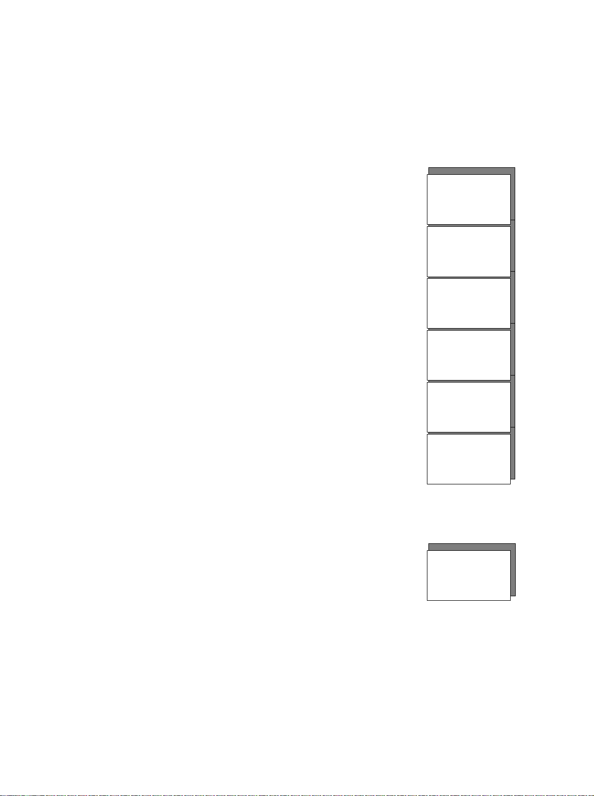
4.1.1 Screen content
Soft key parameters
Graphics
Numerical data
The Centiva/5 display shows all information on a color LCD screen. The
screen is divided into four different areas.
Area # 1.
This area shows the
ventilation parameter
settings aligned with
the specific soft key.
For details refer to
soft keys.
Area # 4
Graphical patient data
and alarm messages
Status information
Area # 2
Area # 1
Area # 2
This area shows the
measured patient
data in graphical
format as well as
alarm messages.
Area # 3
This area shows the
Area # 4
Graphical patient data
and alarm messages
Softkeys for ventilation parameter settings
Area # 4
Status information
Area # 2
Area # 1
Status information
measured patient
data in numeric
format.
Area # 2
Graphical patient data
and alarm messages
Softkeys for ventilation parameter settings
Area # 1
Area # 3
numerical
patient
data
Area # 3
numerical
patient
data
Area # 3
numerical
patient
data
URM Centiva/5, CM-920041, rev. 2.22
4-3
Page 32

4 Concept of operation
Status information
Area # 4.
Area # 4
Status information
This area shows the
status information for
the ventilator.
Area # 2
Graphical patient data
and alarm messages
Area # 3
numerical
patient
data
Softkeys for ventilation parameter settings
Area # 1
4-4
URM Centiva/5, CM-920041, rev. 2.22
Page 33

4 Concept of operation
%
cmH2O
cmH2O
mL
1/Min
L/Min
%
cmH2O
cmH2O
mL
1/Min
cmH2O
%
cmH2O
cmH2O
Sec.
1/Min
cmH2O
%
cmH2O
cmH2O
1/Min
cmH2O
Sec.
N-val
c-val
Val
%
cmH2O
Sec.
cmH2O
4.1.2 Soft keys
Soft keys in VCV
Soft keys in SIMV - VC
Soft keys in Bi-Level
Soft keys in CPAP/PSV
Soft keys in CPAP/Apnea
By using the soft keys the operator selects a parameter to change.
Depending on the current ventilation mode the soft keys are related to
different parameters. Immediately above the soft key the parameter is
displayed in the screen showing the value and units of measure.
Fi O2
50
Rate
10
I : E
1:2.0
Vt
110
Plimit
30
PEEP
OFF
Fi O2
50
Plimit
30
I : E
1:2.0
Rate
10
Vt
110
PEEP
OFF
Fi O2
50
P-Insp
10
I : E
1:2.0
Rate
10
Ramp
0.20
PEEP
OFF
Fi O2
50
Fi O2
50
Rate
10
I : E
1:2.0
Ramp
0.20
Ramp
0.20
P-Insp
10
PEEP
OFF
PEEP
OFF
I-Flow
6.6
PS
10
PS
10
PS
5
PS
10
URM Centiva/5, CM-920041, rev. 2.22
The soft key shows parameter (type) and value
Type
(Val) with blue characters on yellow background.
Activating a soft key will change the background
unit
color from yellow to blue and the character from
blue to yellow. When changing the parameter with
the ComWheel, the current parameter is displayed
as a small character on top to remind the operator
type
of the value (c-val) while making the new
parameter change (N- val). After confirming the changed value the soft
key returns to blue character on yellow background.
4-5
Page 34

4 Concept of operation
2.0:1
1:2.0
I : E
2.0:1
I : E
9.9:1
3:1.0
I : E
4.1.3 I : E ratio soft key
Inverse I:E ratio
Inverse I:E ratio in SIMV-VC mode
APRV I:E ratio in Bi-Level mode
Note
For standard I : E ratio settings from 1:1 to 1:9.9 the I : E ratio soft key‘s
characters and background colors are identical to the other soft keys.
When changing the I : E ratio in all ventilation
modes to inverse values (I>E) (range 1:1 to 4:1)
the user will be notified by a change of the
background color from blue to red and the
character color from yellow to white. After
confirming the changed value the soft key returns to blue character on
yellow background.
Changing the soft key parameter rate in the SIMVVC mode causes a change of the I:E ratio
accordingly to keep the ventilation pattern similar.
When this change in I : E ratio leads to inverse
values (I>E) the user will be notified by a change
of the background color from blue to white and the character color from
yellow to red. After confirming the changed value the soft key returns to
blue character on yellow background.
Only in Bi-Level mode Centiva/5 offers extreme
inverse I:E ratio values to simulate APRV (airway
pressure release ventilation).
When changing the I : E ratio in Bi-Level mode
beyond the inverse I:E ratio level to extreme inverse I:E ratio values
(range 4:1 to 9.9:1) the user will be notified by a change of the
background color from red to brown. After confirming the changed value
the soft key returns to blue character on yellow background.
When changing the ventilation mode from Bi-Level to any other mode,
APRV I:E ratios will not transfer automatically, but the user will be
notified to correct the I:E ratio accordingly by a message “I :E > 4:1 !”.
4-6
URM Centiva/5, CM-920041, rev. 2.22
Page 35

4 Concept of operation
%
cmH2O
mL
1/Min
L/Min
cmH2O
t
4.1.4 Timing parameter
The Centiva/5’s timing parameter in all ventilation modes are:
- ventilation rate (rate)
- inspiration to expiration time ratio (I:E)
TV
Fi O2
50
Plimit
30
I : E
1:2.0
Rate
10
Vt
110
PEEP
Off
Changing the I-Flow setting in the ventilation modes VCV and SIMV-VC
has an impact on the timing, too. In this case the inspiratory pause will
be affected by this parameter.
All timing parameters are relative parameters and do not directly set
absolute times. During changing the setting of one of the timing
parameters Centiva/5 will display the absolute time information on the
screen in the format:
I=xx s, P=yy %, E= zz s
„I“ is inspiration time (T
„P“ is inspiratory pause in % of inspiration time (T
„E“ is expiration time (T
) in seconds
insp
) in seconds.
exsp.
pause
/ T
insp
)
After confirming made changes to one of the timing parameters this
absolute time message in the screen disappears automatically.
t
I-Flow
6.6
URM Centiva/5, CM-920041, rev. 2.22
I= 2.0 s, P= 30%, E=3.0 s
4-7
Page 36

4 Concept of operation
4.1.5 Graphics
The Centiva/5 displays two graphical waveforms on the screen:
- current airway pressure versus time
- current airway flow versus time
The upper waveform shows the airway pressure and contains markers
for the pressure settings, such as PEEP, Pinsp or Plimit.
The lower waveform shows the airway flow.
The display will automatically change to scale to maximize readability of
the waveform.
The graphic waveform data is real time and both waveforms are
synchronized on the same time base.
15
10
5
Paw
cmH2O
40
20
Flow
L/min
-20
-40
4-8
URM Centiva/5, CM-920041, rev. 2.22
Page 37
4 Concept of operation
Val
10
cmH2O
4.1.6 Numerical patient
data
The Centiva/5 displays measured patient data in a numeric format.
The expiratory minute volume is measured
over a period of 60 secs or 10 breaths.
The expiratory tidal volume is measured
during each breath.
The maximum (Peak) airway pressure is
measured during each breath.
The minimum (Min) airway pressure is
measured during each breath.
The inspiratory O2 concentration is measured
at the inspiratory port.
The total patient breath rate is measured over
a period of 60secs or 10 breaths and
represents spontaneous plus mechanical
breaths.
The format of this numeric data field shows
the parameter (Para) with the measured value
(Val) and the unit of measure (unit).
If alarm limits for this particular parameter are available, the upper limit
(UL) and the lower limit (LL) are displayed in the same data field.
MV-E
3.0
TV-E
361
Ppeak
14
Pmin
1
O2-I
21
Rate
Para
cmH2O
12.0
2.5
Liter
mL
21
26
18
%
40
8
1/min
UL
LL
Unit
URM Centiva/5, CM-920041, rev. 2.22
4-9
Page 38

4 Concept of operation
Tube: E 7.5 40%
Battery: 28 min
Adult
No Test
4.1.7 Status information
Vent. mode
NEB
ARC
Battery
Patient type
System Test
The Centiva/5 shows status information in the top portion of the
display. The following describes the status information in order from left
to right appearing on the screen.
The selected ventilation mode is displayed:
“VCV”, “SIMV-VC”, “Bi-Level”, “CPAP/PSV”,
“CPAP/Apnea”.
When nebulization is activated, an icon is displayed
during operation in nebulization mode
When Airway Resistance Compensation is
activated, status information is displayed
giving the selected tube (E=endotracheal,
T= tracheal), size of tube (e.g. 7.5 mm) and level of compensation (e.g.
40%). If ARC is not turned ON this status information field is not
present.
When the system is supplied by the internal
back-up battery the remaining operation
time on battery is displayed. Whenever the
internal battery is being charged, the same status information appears.
If the system is supplied by line (main) supply and the battery is fully
charged this status information field is not present.
Status information about the selected patient type
is displayed with either ”Adult” or “Pedia”
(pediatric).
When the System test is not performed and the
ventilator is started by bypassing the system test,
the “No Test” is displayed. If the system test was
performed prior to the start of the ventilation this status information
field is not present.
Bi-Level
4-10
URM Centiva/5, CM-920041, rev. 2.22
Page 39

4 Concept of operation
Switch off device ? Yes: Enter, No: any button
Only O2
Single gas supply
ASR
Shut down
External DC supply
If the operator has confirmed single gas operation
during the system test, this status information
field displays “Only AIR” for single gas supply with
AIR or “Only O2” for single gas supply with O2. If dual gas supply with
O2 and AIR is confirmed this status information field is not present.
When the Automatic Suction Routine is activated
the status information field reports the different
phases of the ASR procedure:
If ASR is not turned ON this status information field is not present.
When the
“System
Open?” message is displayed on the screen and the ON-OFF button is
activated for longer than 3 seconds, the shut down status information
appears. This shut down information indicates that pushing the
“<Enter>” button (ComWheel), powers down the Centiva/5 or by
pressing any other button the system remains in the normal operation
mode. This status information field overwrites all other status
information fields and covers the entire status information area on the
screen
When an external DC supply (e.g. battery pack)
takes over the mains supply, an icon is displayed to
indicate the power supply by external battery.
- “Pre oxygen” for the pre-oxygenation phase,
- “Suction” for the suction phase,
- “Post oxygen” for the post oxygenation phase.
Pre oxygen
URM Centiva/5, CM-920041, rev. 2.22
4-11
Page 40

4 Concept of operation
4.1.8 ComWheel
Special notice
The ComWheel is turned to change the selected parameter values .
Turing clockwise increases the value or moves up the
cursor in a menu.
Turning counterclockwise decreases the value or
moves down the cursor in a menu.
Pushing the ComWheel confirms a selection.
Confirming a selection returns the soft key background
color from blue to yellow or changes the highlighted area
in a menu. The changed parameter will only become
valid when the ComWheel is pushed for confirmation.
When a screen message asks for “<Enter>”, the system asks the
operator to push the ComWheel to confirm an action.
4-12
URM Centiva/5, CM-920041, rev. 2.22
Page 41

4 Concept of operation
%
%
4.1.9 Changing a
parameter
The following shows how a parameter change is made.
This is the parameter field before we start.
Select the FiO2 soft key.
Notice the color change.
Turn the ComWheel clockwise to increase the value to
50%.
Notice the value change.
The current value is shown on the top and the new
value in the middle.
Confirm the selection by pushing the ComWheel.
This is the parameter field after the change.
FiO2
30
30
30
FiO2
30
50
FiO2
FiO2
50
URM Centiva/5, CM-920041, rev. 2.22
4-13
Page 42

4 Concept of operation
A R C
Exit
4.1.10 Menu button
To select additional functions or infrequently used parameters push the
menu button.
Within the Centiva/5’s screen the
main menu will open. It is here
that most functions are directly
accessible.
Submenus can be opened for
detailed parameter settings.
Stand-by
A S R
ON
ON
Parameter menu
Alarm limits
Alarm AUTOSET
Vent. modes
Nebulizer
ON
System test
4-14
URM Centiva/5, CM-920041, rev. 2.22
Page 43

4 Concept of operation
4.1.11 Selecting a menu
topic
To select a specific menu topic turn the ComWheel to select the menu
option and push the ComWheel to confirm the selection.
Turning the ComWheel clockwise will move the cursor
up the menu.
Turing the ComWheel counterclockwise will move the
cursor down in the menu.
Pushing the ComWheel will confirm the selection
URM Centiva/5, CM-920041, rev. 2.22
4-15
Page 44

4 Concept of operation
A R C
Exit
A R C
Exit
4.1.12 Activating a menu
function
The following shows how to activate a menu selection.
Open the main menu by pushing the menu button.
The main menu will appear in the screen.
Rotate the ComWheel to select the Alarm AUTOSET
function.
The selected function will be highlighted in the
menu.
Confirm the selection by pushing the ComWheel.
The function “Alarm AUTOSET” is activated and the
menu closes automatically.
Stand-by
A S R
Parameter menu
Alarm limits
Alarm AUTOSET
Vent. modes
Nebulizer
System test
Stand-by
A S R
Parameter menu
Alarm limit s
Alarm AUTOSET
Vent. modes
Nebulizer
System test
ON
ON
ON
ON
ON
ON
4-16
URM Centiva/5, CM-920041, rev. 2.22
Page 45

4 Concept of operation
A R C
Exit
A R C
Exit
Buzzer
PS endflow
Rate min
Rate max
Apn.del.
4.1.13 Submenus
Parameter menu
Alarm limits
The following selections in the main menu open the submenus :
• Parameter menu
• Alarm limits
Ventilation modes (Vent. Modes)
•
• Airway Resistance Compensation (ARC)
These submenus open upon selecting the topic in the main menu.
Stand-by
A S R
Parameter menu
Alarm limits
Alarm AUTOSET
Vent. modes
Nebulizer
System test
ON
ON
ON
I-flow
PS ramp
Trigg.
ByFlow
Time window
Previous menu
10.0 L/m
0.20 s
3.0 L/m
3.0 L/m
100%
Exit
60%
25%
Stand-by
A S R
Parameter menu
Alarm limits
Alarm AUTOSET
Vent. modes
Nebulizer
System test
ON
ON
ON
MV max
MV min
Leakage
Pmax
Previous menu
1.7 L
0.5 L
25%
40cmH2O
20 Sec
40/Min
8/Min
Exit
URM Centiva/5, CM-920041, rev. 2.22
4-17
Page 46

4 Concept of operation
A R C
Exit
A R C
Exit
CPAP/Apnea
CPAP/PSV
VCV
Vent. modes
A R C
Stand-by
A S R
Parameter menu
Alarm limits
Alarm AUTOSET
Vent. modes
Nebulizer
System test
Stand-by
A S R
Parameter menu
Alarm limits
Alarm AUTOSET
Vent. modes
Nebulizer
System test
ON
ON
ON
ON
ON
ON
SIMV - VC
Bi-Level
Previous menu
Exit
Endot.tube
Trach.tube
Diameter 7.5
Compensat. 75 %
Previous menu
OFF
OFF
Exit
4-18
URM Centiva/5, CM-920041, rev. 2.22
Page 47

4 Concept of operation
A R C
Exit
CPAP/Apnea
CPAP/PSV
VCV
4.1.14 Open a submenu
Push the Menu button to open the main menu,
Select the “Vent. modes” by opening the main
menu and rotating the ComWheel to the “Vent.
Modes” selection.
Confirm this selection by pushing the ComWheel which
opens the “Vent. Modes” submenu.
The “Vent. modes” submenu allows you to select
the appropriate ventilation mode by rotating the
ComWheel and confirming the selection by
pushing the ComWheel.
Stand-by
A S R
Parameter menu
Alarm limits
Alarm AUTOSET
Vent. modes
Nebulizer
System test
SIMV - VC
Bi-Level
Previous menu
ON
ON
ON
Exit
URM Centiva/5, CM-920041, rev. 2.22
4-19
Page 48

4 Concept of operation
A R C
Exit
A R C
Exit
4.1.15 Change a
parameter in a sub menu
The following shows how to change the parameter “MV max” in the
alarm limit submenu.
Open the main menu by pushing the menu button.
The main menu will appear in the screen.
Stand-by
A S R
Parameter menu
Alarm limits
Alarm AUTOSET
Vent. modes
Nebulizer
System test
Select the “Alarm limits” by rotating the ComWheel.
The selected function will be highlighted in the
menu.
Stand-by
A S R
Paramet er menu
Alarm limits
Alarm AUTOSET
Vent. m odes
Nebulizer
System test
Confirm the selection by pushing the ComWheel. The
“Alarm limits” sub menu will open.
ON
ON
ON
ON
ON
ON
4-20
URM Centiva/5, CM-920041, rev. 2.22
Page 49

4 Concept of operation
Rate min
Rate max
Apn.del.
Rate min
Rate max
Apn.del.
Rate min
Rate max
Apn.del.
1.7 L
The “Alarm limits” submenu opens.
Select the “MV max” by rotating the ComWheel.
MV max
MV min
Leakage
40cmH2O
Pmax
20 Sec
40/Min
Previous menu
Exit
1.7 L
0.5 L
25%
8/Min
The selected function will be highlighted in the
menu.
Confirming the selection highlights the value in the “MV
max” setting.
The selected parameter value is highlighted.
MV max
MV min
Leakage
Pmax
Previous menu
MV max
MV min 0.5 L
Leakage
Pmax
Previous menu
1.7 L
0.5 L
25%
40cmH2O
20 Sec
40/Min
8/Min
Exit
25%
40cmH2O
20 Sec
40/Min
8/Min
Exit
URM Centiva/5, CM-920041, rev. 2.22
4-21
Page 50

4 Concept of operation
Rate min
Rate max
Apn.del.
2.5 L
Rate min
Rate max
Apn.del.
4.1.16 Alarm silence
Rotating the ComWheel adjusts the new value.
The MV max is changed to 2.5 L.
Confirming the selection activates the new value for
the alarm limit MV max.
Selecting the “Previous menu” selection returns
you to the main menu. Confirming the “exit”
function will close the menu window or if left open
for 30 secs the menu will automatically close.
MV max
MV min 0.5 L
Leakage
Pmax
Previous menu
MV max
MV min
Leakage
Pmax
Previous menu
25%
40cmH2O
20 Sec
40/Min
8/Min
Exit
2.5 L
0.5 L
25%
40cmH2O
20 Sec
40/Min
8/Min
Exit
Pushing the alarm silence button during a high priority
alarm silences the audible alarm for two (2) minutes. A
clock in the screen starts displaying the remaining alarm
silence time. When an alarm becomes inactive , the alarm message
stays on the screen, but changes color from red to yellow and the
audible alarm turns OFF. This is to remind the operator that an alarm
situation had occurred . Pushing the alarm silence button again will
remove the yellow alarm message from the screen.
4-22
URM Centiva/5, CM-920041, rev. 2.22
Page 51

5 Preparation
In this section
5.1 Electrical supply 5-2
5.1.1 Mains supply 5-2
5.1.2 Back-up battery supply 5-4
5.2 Gas supply 5-5
5.2.1 Dual gas supply 5-5
5.2.2 Single gas supply 5-6
5.3 Set up of expiration valve 5-7
5.4 Breathing gas conditioning 5-8
5.5 Breathing circuit 5-9
5.5.1 Connection with HME 5-9
5.5.2 Connection with active humidifier 5-10
5.6 Placing the device 5-12
5.6.1 Control panel 5-12
5.6.2 Entire system 5-14
5.7 Turn ON and OFF 5-15
5.8 Self test 5-16
5.8.1 Power-up test 5-16
5.8.2 System test 5-17
5.8.3 In-operation test 5-18
5.9 Select the type of patient 5-20
5.11 Starting the ventilator 5-22
URM Centiva/5, CM-920041, rev. 2.22
5-1
Page 52

5 Preparation
5.1 Electrical supply
5.1.1 Mains Supply
The Centiva/5 is designed to operate from electrical supplies:
• Mains supply
• External battery.
The system will treat all of these supply sources as a main supply.
Verify your local mains supply voltage matches the rated device’s
voltage on the serial plate (rear side).
Connect the power cord to the mains inlet on the rear of the device.
24V/3A DC
Serial plate
Caution. U.S. Federal laws restrict this device
to sale by or on the order of a licensed medical
practitioner.Outside the U.S.A. check local
laws for any restriction that may apply.
Lin
e
s
wit
ch
Line
i
nl
e
t
O2 AIR
280 ... 600 kPa or 40 ... 80 PSI
Connect the power cord to the wall outlet.
Switch ON the mains switch.
Verify the ON-OFF button on the front is lit.
5-2
URM Centiva/5, CM-920041, rev. 2.22
Page 53

5 Preparation
External battery
Place the external battery (option) below the Centiva/5 housing and
lock the battery housing to the Centiva/5 housing .
Caution. U.S. Federal laws restrict this device
to sale by or on the order of a l icensed medical
practi tioner .Outsid e the U.S.A . chec k local
laws for any restriction that may apply.
2
4
V
D
C
inle
24V/3A DC
t
O2 AIR
280 ... 600 kPa or 40 ... 80 PSI
Out: 24V/
3 A DC
In: 27,5V/
0,25 A DC
3,15 A T
Locking
Connect the DC supply power cord from the external battery pack to the
blue inlet and verify proper locking of the connector.
Special Notice
Verify the ON-OFF button on the front is lit.
Verify the external battery is fully charged prior to usage. When fully
charged the battery’s charging indicator is lit permanently in green.
When powered by the external battery pack, Centiva/5
displays an battery icon in the top left of the screen
For more details to the external battery refer to the operation manual of
this accessory.
URM Centiva/5, CM-920041, rev. 2.22
5-3
Page 54

5 Preparation
5.1.2 Back-up battery
supply
Special notice
WARNING
The Centiva/5 is equipped with an internal back-up battery supply that
provides at least 30 minutes of operation upon loss of electrical main
supply.
This back-up supply will automatically switch on whenever the main
supply is lost and will maintain uninterrupted operation of the
Centiva/5.
When operating on the back-up battery, the system will display a
message in the operation screen (no line supply).
At the same time the battery status in the
status line of the screen will display the
remaining operation time on battery.
When operating on back-up battery the system reduces power
consumption to save energy for extended battery life by turning off the
expiration valve heating system and by reducing the screen brightness.
Upon restoring line (main) supply the system automatically switches
back to the line supply and changes the message in the screen (no line
supply) from red to yellow.
Upon restoring line (main) supply the system automatically starts
recharging the internal battery.
Whenever the Centiva/5 is supplied by any main supply (line, 24 VDC
or external battery) and the system is turned ON, the internal back-up
battery is recharged. The recharging process is indicated by the battery
status displayed in the status line of the screen (with the timer counting
up ). The re-charger is not active when the system is turned OFF.
Battery 28 min
Do not use the internal back-up battery as a main supply.
When turning the Centiva/5 ON without line (main) supply, the system
powers up on the back-up battery to allow opening of the system test
menu only, (e.g. to release the expiration valve for cleaning purpose).
Without line (main) supply the Centiva/5 will not go into a ventilation
mode. After having passed the power-up test and the system test, the
back-up battery function is activated and will perform uninterrupted
operation upon loss of line (main) supply.
5-4
URM Centiva/5, CM-920041, rev. 2.22
Page 55

5.2 Gas supply
5 Preparation
5.2.1 Dual gas supply
The Centiva/5 is equipped with an electronic O2/AIR mixer to provide a
wide range of inspiratory oxygen concentrations. This requires the
supply of both O2 and AIR gases. The gas supply range for both gases
ranges from 40 to 80 PSI. The Centiva/5 is protected against
overpressure up to 140 PSI. The Centiva/5 provides high peak flow
capability for optimized pressure support ventilation. This capability
requires a flow of 120 l/min per gas.
Verify your gas supply pressure matches the pressure range mentioned
above.
24V/3A DC
Connect the O2 gas supply hose to the O2 gas inlet on the rear of the
device. Connect the O2 gas supply hose to the wall outlet and check
the connection for leaks.
Connect the AIR gas supply hose to the AIR gas inlet on the rear of the
device. Connect the AIR gas supply hose to the wall outlet and check
the connection for leaks.
Caution. U.S. Federal laws restrict this device
to sale by or on the order of a licensed medical
practitioner.Outside the U.S.A. check local
laws for any restriction that may apply.
O2 gas
A
IR
g
a
s
i
O2 AIR
nl
280 ... 600 kPa or 40 ... 80 PSI
e
t
i
nle
t
WARNING
WARNING
URM Centiva/5, CM-920041, rev. 2.22
Use only gas supply hoses in compliance with the local
standards. Incorrect connecting of O2 and AIR supply can result
in risk to the patient.
Only supply the system with dry and clean gases to prevent water,
oil or particles to enter the system. Dirt, water or oil can damage
the system and may result in risk to the patient.
5-5
Page 56

5 Preparation
OnlyAIR
Only O2
5.2.2 Single gas supply
Special notice
The Centiva/5 needs at least 40 PSI from the gas supply for proper
operation. If this pressure level is not sufficient from one gas source the
system automatically switches to the gas supply which has sufficient
pressure and displays an alarm message on the screen.
The Centiva/5 can operate with a single gas supply without alarms.
When the system recognizes the single gas supply during the system
test it prompts a message on the screen and asks for single gas
operation.
In the event of a single gas supply (e.g. AIR) the following screen will
appear during system test.
Restoring the O2
supply at this time in
the system test
removes the message
automatically and the
system test proceeds.
Confirming the single
gas operation for AIRsupply by pushing the
ComWheel to <Enter>
will cause the system test to proceed , but all tests that use O2 will be
skipped .
After the system test is completed and ventilation has started, the
system will change the default setting for FiO2 according to the selected
single gas operation to avoid nuisance alarms. In the single gas AIR
operation the FiO2 default is 21 %. In the single gas O2 operation the
FiO2 default is 100%.
The single gas operation is displayed in the status
line with "Only Air" when lacking O2 supply or “Only
O2” when lacking AIR supply.
Restoring the missing gas during operation allows the unit to operate in
the dual gas supply mode . The system will still display the selected
single gas supply mode until a new system test is performed with both
gases available.
System test Rev. x.nn
No O2 gas supply
Check O2 gas supply or
for single gas AIR-supply press <Enter>
Centiva/5
5-6
URM Centiva/5, CM-920041, rev. 2.22
Page 57

5.3 Set up of expiration valve
The Centiva/5’s expiration valve is removable from the device for easy
cleaning. Upon re-insertion it will lock in automatically for safe
operation.
The valve assembly consists of three components:
Special notice
• the valve block
• the PEEP membrane
•
Verify the PEEP membrane assembly is inserted in the valve block with
the note “TOP” facing you.
Verify the membrane plate (stainless steel) is positioned on top of the
membrane assembly.
The expiratory valve assembly
should slide easily into the
mating slot on the side of the
ventilator
The expiration valve assembly should be inserted smoothly . If you feel
a high resistance when inserting the assembly do not force it in but
check for proper assembly of the expiration valve.
5 Preparation
assembly
the membrane plate
URM Centiva/5, CM-920041, rev. 2.22
5-7
Page 58

5 Preparation
5.4 Breathing gas conditioning
An intubated patient’s physiological function for heating and
humidifying the breathing gases is bypassed while on a ventilator.
Therefore, it is necessary to care for this missing function by using either
a passive heat and moisture exchanger (HME) or an active heated
humidifier.
The use of high efficient humidification and heating with low flow
resistance is preferred.
CAUTION
Do not use active and passive humidification at the same time in
the same breathing circuit !
5-8
URM Centiva/5, CM-920041, rev. 2.22
Page 59

5.5 Breathing circuit
Insp. line
I
O
A
WARNING
5.5.1 Connection with
HME
5 Preparation
The Centiva/5 ventilator can be used with all approved breathing
circuits and components, noted in the Centiva/5 accessories list.
In pediatric ventilation, in general (tidal volumes less than 300 ml), the
use of pediatric breathing circuits is preferred.
To avoid restriction of the ventilator’s performance, use of breathing
circuits with low resistance and a flow optimized y-piece is preferred.
During the system test, compliance, resistance and leakage rate of the
breathing circuit is measured and displayed.
Do not use antistatic or conductive tubes or breathing circuits.
Risk of electrical hazard to the patient !
Use of a support arm (option) to hold up the breathing circuit between
the device and patient is recommended.
Connect inspiratory tube to the right, front 22 mm
connector (inspiratory output).
Connect expiratory tube to the left, front 22 mm connector
(expiratory input).
Connect y-piece to open end of inspiratory and expiratory tube
Connect HME to the y-piece
and connect patient to the
HME.
Check for proper seating of
all connections.
Bi-Level / ASB
15
10
5
Paw
mbar
40
20
Flow
L/min
-20
-40
Fi02
21
%
Rate
12
1/min
Tube : E 7. 5 50%
I:E
1:2
Ramp
0.2
Centiva/5
dult
12
MV-E
2
4.2
Liter
Vt-E
350
mL
21
Ppeak
14
cmH2O
Pmin
3
cmH2O
25
O2-I
18
21
%
40
Rate
8
12
P-Insp
sec
1/min
PEEP
P-ASB
10
3
5
cmH2O
cmH2O
cmH2O
URM Centiva/5, CM-920041, rev. 2.22
HME
Exp. line
5-9
Page 60

5 Preparation
I
O
A
I
O
A
5.5.2 Connection with
active humidifier
Adjust the humidifier rail of the
cart according to the height
requirement of the active
humidifier so that between the
upper level of the humidifier and
the lowest part of the drawer or
Bi-Level / ASB
15
10
5
Paw
mbar
40
20
Flow
L/min
-20
-40
Fi02
21
%
Rate
12
1/min
Tube : E 7.5 50%
I:E
1:2
Ramp
P-Insp
0.2
10
sec
cmH2O
plate of the cart is a minimum of
15 cm.
Release the screw in front of the
rail mount to change the
position of the rail and tighten it,
when the correct position is found.
Place the active humidifier onto the rail and properly fix it there.
Fill humidifier chamber or use a
Bi-Level / ASB
Tube : E 7.5 50%
pre-filled humidifier chamber
according to manufacturer’s
advice.
15
10
5
Paw
mbar
40
20
Flow
L/min
-20
-40
Fi02
Rate
I:E
Ramp
21
%
P-Insp
12
1:2
0.2
10
1/min
sec
cmH2O
Connect humidifier electrical
supply according to
manufacturer’s advice.
Turn ON humidifier and verify
proper function.
PEEP
3
cmH2O
PEEP
3
cmH2O
Centiva/5
dult
MV-E
4.2
Vt-E
350
Ppeak
14
Pmin
O2-I
21
Rate
12
P-ASB
Centiva/5
dult
MV-E
4.2
Vt-E
350
Ppeak
14
Pmin
O2-I
21
Rate
12
P-ASB
cmH2O
12
2
Liter
mL
21
cmH2O
3
cmH2O
25
18
%
40
8
1/min
5
cmH2O
12
2
Liter
mL
21
cmH2O
3
cmH2O
25
18
%
40
8
1/min
5
5-10
URM Centiva/5, CM-920041, rev. 2.22
Page 61

5 Preparation
I
O
A
Connect an inspiratory tube from the right, front 22 mm
connector of the Centiva/5 to the inlet of the humidifier
chamber.
Connect the inspiratory tube from to the outlet of the humidifier
chamber to the y-piece.
Connect an expiratory tube from the left, front 22 mm
connector of the Centiva/5 and to a water trap.
Connect another expiratory
tube from the water trap to
the y-piece.
Water trap
Bi-Level / ASB
15
10
5
Paw
mbar
40
20
Flow
L/min
-20
-40
Fi02
21
%
Rate
12
1/min
Tube : E 7.5 50%
I:E
1:2
CAUTION
When using active humidifiers do not use HMEs between y-piece
and patient at the same time. This may result in increased
breathing resistance and risk to the patient .
Special notice
Active humidifiers in general increase the resistance of the breathing
system. Care should be taken to keep the resistance as low as possible.
Ramp
Centiva/5
dult
12
MV-E
2
4.2
Liter
Vt-E
350
mL
21
Ppeak
14
cmH2O
Pmin
3
cmH2O
25
O2-I
18
21
%
40
Rate
8
12
1/min
P-Insp
PEEP
0.2
sec
P-ASB
10
3
5
cmH2O
cmH2O
cmH2O
URM Centiva/5, CM-920041, rev. 2.22
5-11
Page 62

5 Preparation
I
O
5.6 Placing the device
5.6.1 Control panel
For better visibility and easy handling the Centiva/5 control panel can
be adjusted to optimize the viewing angle.
To adjust the viewing angle, the
upper part of the control panel
can be moved forward or
backward.
The control panel can be detached from the main engine and mounted
a distance of up to 3 meters away from the main engine.
Ramp
0.2
Centiva/5
Adult
12
MV-E
2
4.2
Liter
Vt-E
350
mL
21
Ppeak
14
cmH2O
Pmin
3
cmH2O
25
O2-I
18
21
%
40
Rate
8
12
1/min
P-Insp
PEEP
P-ASB
10
3
sec
5
cmH2O
cmH2O
cmH2O
Bi-Level / ASB
15
10
5
Paw
mbar
40
20
Flow
L/min
-20
-40
Fi02
21
%
Rate
12
1/min
Tube : E 7. 5 50%
I:E
1:2
For this application use the optional extension cable and mounting
accessories.
Positioning of control panel
• At the main engine with adjustable viewing angle
• At a wall rail mount (optional) with adjustable viewing angle
At a bed mount (optional) with adjustable viewing angle
•
5-12
URM Centiva/5, CM-920041, rev. 2.22
Page 63

5 Preparation
To mount the Centiva/5 control panel away from the Centiva/5 main
engine , follow the instructions below.
Place the selected mounting bracket to the desired position.
Turn OFF the Centiva/5.
Move control panel to a full angled position.
Press both stainless steel buttons of the bracket mount together to
release the locking mechanism.
Move the control panel carefully to the front and up.
Disconnect the control panel from the main engine.
Place the control panel onto the selected bracket.
Connect control panel and control panel bracket and secure proper
seated connector.
Press both stainless steel buttons of the bracket mount together to
release the locking mechanism. Insert the bracket and release the two
buttons to activate the locking mechanism.
Reconnect the control panel and main engine using the extension
cable.
Turn ON the Centiva/5 and check for proper function by passing the
“power-up” test.
WARNING
Do not disconnect the control panel during operation. This may
result in risk to the patient.
URM Centiva/5, CM-920041, rev. 2.22
5-13
Page 64

5 Preparation
H
ous
i
g
o
t
I
O
A
5.6.2 Entire system
CAUTION
Placement of the entire unit or main engine:
• On the trolley (optional)
• On other flat surfaces
On a wall rail mount (optional)
•
• On an ICU cabinet
When placing the
ventilator on the optional
trolley ensure that the feet
match with the trolley’s
receptacles.
Ensure the locking
mechanism locks in,
when the device is
properly placed.
To release the device pull
the metal knob of locking
mechanism forward and
remove the device.
Hous
Bi-Level / ASB
Tube : E 7 . 5 50%
15
10
5
Paw
mbar
40
20
Flow
L/min
-20
-40
Fi02
Rate
I:E
21
%
t
o
fo
g
in
Ramp
12
1:2
1/min
n
i
p
g
in
k
c
o
L
Centiva/5
dult
12
MV-E
2
4.2
Liter
Vt-E
350
mL
21
Ppeak
14
cmH2O
Pmin
3
cmH2O
25
O2-I
18
21
%
40
Rate
8
12
P-Insp
0.2
sec
1/min
PEEP
P-ASB
10
3
5
cmH2O
cmH2O
cmH2O
f
n
Always ensure proper seating of the system and activated locking
mechanism, when applicable.
o
5-14
URM Centiva/5, CM-920041, rev. 2.22
Page 65

5.7 Turn ON and OFF
I
O
A
5 Preparation
Turn ON
Turn OFF
The Centiva/5’s ON-OFF button is located on the lower right side of the
ventilator engine .
When supplied with line (mains) power (line switch on the rear should
always be turned ON) the ON-OFF button is illuminated by a green light
and the unit turns ON when the ON-OFF button is pressed.
If no mains supply is
present, or the mains
switch is off, the ON-OFF
button is not illuminated.
Pressing the ON-OFF
button with no mains
supply activates the
internal back-up battery to
allow for service activities,
such as removing the
expiratory valve assembly .
For safety reasons the
Centiva/5 will not go into
normal operation when the main supply is missing.
Bi-Level
15
10
5
Paw
cmH2O
40
20
Flow
L/min
-20
-40
Fi02
Rate
21
12
%
1/min
Tube : E 7.5 50%
I:E
Ramp
1:2
0.2
Centiva/5
dult
12
MV-E
2
5.2
Liter
Vt-E
350
mL
21
Ppeak
14
cmH2O
Pmin
3
cmH2O
25
O2-I
18
21
%
40
Rate
8
18
P-Insp
sec
1/min
PEEP
PS
10
3
5
cmH2O
cmH2O
cmH2O
The Centiva/5 can only be turned OFF when the patient is not being
ventilated and is disconnected (Status: System open ?).
In the non-ventilating
“System open ?”
mode, or in any other
non-ventilating mode,
press and hold the ONOFF button for
approximately 3 secs.
Turn OFF device? Yes= Enter , No= any button
Centiva /5
System test Rev. 2.1n
System test OK. To start ventilation <Enter>
Compliance 2.3 ml/cmH2O
Resistance 0.8 cmH2O/L/s
Leakage 15 ml/min
Adult Pediatric
A message appears asking the user to either turn off the system by
confirming with the enter key (ComWheel) or returning to the current
status by pressing any other key.
ON/OFF
URM Centiva/5, CM-920041, rev. 2.22
5-15
Page 66

5 Preparation
Start system test <Enter>
I
O
A
5.8 Self test
5.8.1 Power-up test
The Centiva/5 software includes self tests that determine if the
operating software is functioning properly and if the electronic and
pneumatic circuits are functional. The self tests include:
• Power-up test
• System test
In-operation test
•
The power-up test
starts automatically
when the system is
turned ON. The
following screen is
displayed:
System test Rev. x.nn
Test active, wait for 5 secs
Centiva/5
Message box
The power-up test
takes at least 5 secs.
The test time counts
down on the screen.
During the power-up test, the ventilator checks the proper function of all
essential electronic components. If a malfunction is identified during
this power up test, the corresponding message appears in the message
box area. For details of
error messages refer to
section 8 “Alarms and
messages”.
After having passed the
System test Rev. x.nn
Complete system set up, seal y-piece
Centiva/5
power-up test, the
Centiva/5 prompts with
a short audible sound
and moves to the “Start
Adult Pediatric
system test” screen:
Connect the breathing
circuit to the system and
seal the Y-piece by placing
the open end onto the
sealer on the exp. valve
assembly.
Bi-Level
Tube : E 7.5 50%
15
10
5
Paw
cmH2O
40
20
Flow
L/min
-20
-40
Fi02
Rate
I:E
21
%
Ramp
12
1:2
0.2
1/min
Centiva/5
dult
12
MV-E
2
5.2
Liter
Vt-E
350
mL
21
Ppeak
14
cmH2O
Pmin
3
cmH2O
25
O2-I
18
21
%
40
Rate
8
18
1/min
P-Insp
PEEP
PS
10
3
sec
5
cmH2O
cmH2O
cmH2O
5-16
Stopper
URM Centiva/5, CM-920041, rev. 2.22
Page 67

5 Preparation
System test
5.8.2 System test
Push the ComWheel to confirm the <Enter> command.
This starts the system
test.
This system test takes
at least 40 secs. The
test time counts down
on the screen.
During the system test, the system will check the proper function of all
pneumatic and electronic components together with the function of the
attached breathing circuit . If any malfunction is identified during this
system test, the corresponding message appears in the message box
area. For details of error messages refer to section 8 “Alarms and
messages”.
After having passed the
system test, the system
prompts the user to
open the Y-piece which
allows the testing of
inspiratory resistance.
Disconnect the Y-piece from the sealer.
The system will recognize that the Y-piece is open automatically and will
proceed with the system test.
Test active, wait for 35
System test Rev. x.nn
Open Y-piece
Centiva/5
Message
Adult
Centiva/5
Adult
URM Centiva/5, CM-920041, rev. 2.22
5-17
Page 68

5 Preparation
5.8.3 In-operation test
CAUTION
CAUTION
After measuring the
inspiratory resistance,
the Centiva/5 displays
the following screen:
The compliance and
leakage values
represent the entire
breathing circuit and
ventilator. This value is
used for the internal compliance compensation.
The resistance value represents the inspiratory resistance of the
breathing circuit and ventilator to the y-piece. This value is used for the
internal resistance compensation .
The nebulizer flow value represents the measured nebulizer flow of the
connected nebulizer. Incase no nebulizer was connected during system,
the last measured nebulizer flow is displayed with a note added (last
value).
In case the expiration flow sensor was readjusted during system test the
according message “Exp. flow sensor data re-adjusted” is displayed.
Values for compliance, resistance and leakage depend upon the
breathing circuit used.
Values for nebulizer flow depend upon the nebulizer used (if applicable)
For details to the nebulizer test refer to section 6. 3.10. “Nebulizer”.
Filters and HMEs may significantly increase the resistance values.
System test Rev. x.nn
System test OK. To start ventilation <Enter>
Compliance 2.3 ml/mbar
Resistance 0.8 mbar/L/s
Leakage 15 ml/min
Nebulizer flow 7,0 l/min
Exp. flow sensor data re-adjusted
Centiva /5
Adult
Do not perform the system test with a filter or HME on the
breathing circuit. Inappropriate pressure and flow compensation
may result.
Other breathing circuit designs, such as co-axial systems, may increase
the measured resistance values.
Always use breathing circuits with low inspiratory resistance.
During operation the Centiva/5 continuously checks all safety relevant
functions and parameters. If a malfunction is identified, the system will
display alarms or messages on the screen. For details of error
messages refer to section 8 “ Alarms and messages”.
5-18
URM Centiva/5, CM-920041, rev. 2.22
Page 69
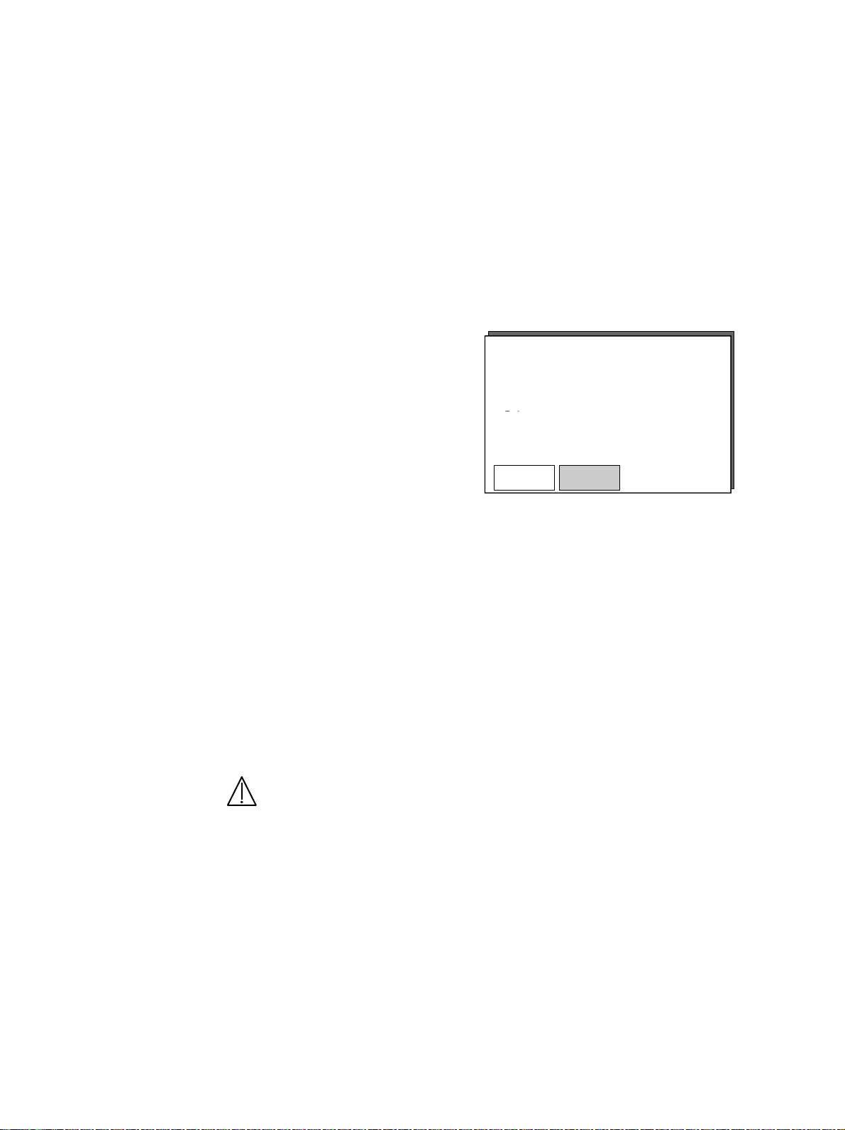
5.9 Select the type of patient
System test
The Centiva/5 allows for the pre-adjustment of ventilator settings and
alarm limits according to two different types of patients:
CAUTION
• Adult
• Pediatric
Prior to the system
tests the user can
select the desired
patient type on the
screen by pressing
either of the soft keys
below the patient
types.
Activating the new patient type changes the color of the button in the
screen from gray to yellow to prompt the change.
This pre-selection is important to establish default settings in the
different ventilation modes. For details see section 6.1.2 “Default
ventilation values”.
The selected patient type is displayed during system test in the screen’s
lower left corner and during operation within the status information
area.
The default settings provide a minimum ventilation for the
selected patient type, while the patient is connected and
prepared. After preparation and proper connection the settings
must be adjusted according to the patient’s needs.
Centiva/5
System test OK. To start ventilation
Compliance 2.3 ml/cmH2O
Resistance 0.8 cmH2O/L/s
Leakage 15 ml/min
Adult
Pediatric
5 Preparation
URM Centiva/5, CM-920041, rev. 2.22
5-19
Page 70

5 Preparation
System Test
Bypass system
Unlock expiration
Calibrate O2
5.10 System test menu
Bypass system test
After having successfully passed the power-up and/or the
system tests the system test menu can be activated by
pressing the menu button.
The system test menu
appears and allows for
Centiva/5
the selection of certain
service functions.
Selecting “Exit” closes
the system test menu
Complete system set up, seal YStart system test by pressing
without any activity.
Adult
Service functions available in the system test menu are:
• Bypass system test
• Unlock expiration valve
• Calibrate O2 sensor
The required system test is bypassed with
this function.
Bypass system test
Unlock expiration valve
Calibrate O2 sensor
Exit
Exit
5-20
WARNING
CAUTION
Use the system test bypass only in case of emergency.
In this situation the system uses the compliance and resistance
data from the last system test for all internal compensations. If
the current breathing circuit differs significantly to the past circuit,
differences in ventilation parameters due to changes in the
compensation process are possible. This may result in risk to the
patient.
Starting the ventilator without having performed the system test will
result in a status display “no test” to remind the user that the system
was started without a system test and to perform the system test as
soon as possible.
URM Centiva/5, CM-920041, rev. 2.22
Page 71

5 Preparation
Unlock expiration valve
O2 sensor calibration
This function releases the expiration valve
assembly.
Releasing the
expiration valve is
necessary for cleaning
purposes only.
After inserting the expiration
valve it will automatically
lock in place and the
system performs a powerup test.
Releasing the expiratory
valve will work with
internal backup battery
power.
Locking
only works with line (mains) power supply.
System test Rev. x.nn
Expiration valve unlocked
Ready to be removed from device
This function starts an automatic O
details refer to section 9 “Maintenance”.
Bypass system test
Unlock expiration valve
Calibra t e O2 se ns or
Exit
Centiva/5
sensor calibration procedure. For
2
URM Centiva/5, CM-920041, rev. 2.22
5-21
Page 72

5 Preparation
5.11 Starting the ventilator
After having passed the
system test the
Centiva/5 will go to
normal operation when
the <Enter> button
(ComWheel) is pressed.
Push the ComWheel to start ventilation.
The Centiva/5 defaults to the ventilation mode ”Bi-Level“ with the
ventilator settings and alarm limits set according to the selected patient
type.
Centiva /5
System test Rev. x.nn
System test OK. To start ventilation <Enter>
Compliance 2.3 ml/mbar
Resistance 0.8 mbar/L/s
Leakage 15 ml/min
Nebulizer flow 7,0 l/min
Adult
5-22
URM Centiva/5, CM-920041, rev. 2.22
Page 73

6 Operation
In this section
6.1 Adjust ventilation modes 6-2
6.1.1 Select a ventilation mode 6-2
6.1.2 Default ventilation values 6-3
6.1.3 Changing ventilation modes 6-4
6.2 Adjust ventilation parameters 6-6
6.2.1 VCV 6-6
6.2.2 SIMV-VC 6-9
6.2.3 Bi-Level 6-12
6.2.4 Bi-Level/PSV 6-14
6.2.5 CPAP/PSV 6-17
6.2.5 CPAP/Apnea 6-19
6.3 Additional functions 6-21
6.3.1 Standby 6-22
6.3.2 ASR (Automatic Suction routine) 6-24
6.3.3 Parameter menu 6-27
6.3.4 Alarm lim its 6-32
6.3.5 Alarm AUTOSET 6-38
6.3.6 ARC (Airway Resistance Compensation) 6-41
6.3.7 NEB (Nebulizer drug delivery) 6-44
6.3.8 System test 6-50
6.3.9 NIV (Non Invasive Ventilation) 6-51
6.3.10 APD (Automatic Patient Detection) 6-53
6.3.11 OCV (Online O2 sensor Calibration) 6-54
6.3.12 Short cuts 6-55
URM Centiva/5, CM-920041, rev. 2.22
6-1
Page 74

6 Operation
A R C
Exit
CPAP/Apnea
CPAP/PSV
VCV
6.1 Adjust ventilation modes
6.1.1 Select a ventilation
mode
The Centiva/5 uses the “Bi-Level” as the default mode.
The system uses default settings according to the selected patient type
to provide a minimum level of ventilation performance.
To change the default ventilation mode to another mode
open the main menu with the menu button.
Using the ComWheel select “Vent. Modes” to access
the ventilation modes menu.
The “Vent. Modes” topic is highlighted.
Stand-by
A S R
Parameter menu
Alarm limits
Alarm AUTOSET
Vent. modes
Nebulizer
System test
Confirm the selection by pushing the ComWheel.
ON
ON
ON
6-2
The ventilation modes menu appears.
SIMV - VC
Bi-Level
Make your selection with the ComWheel for the
desired ventilation mode and confirm the selection
by pushing the ComWheel.
Previous menu
Exit
Adjust the ventilation parameter settings to the patient’s needs and set
the alarm limits accordingly.
URM Centiva/5, CM-920041, rev. 2.22
Page 75

6 Operation
6.1.2 Default ventilation
values
Pediatric
When starting the Centiva/5 the system will provide default ventilator
settings to enable easy preparation of the patient.
These settings are designed for the selected patient range to maintain a
minimum ventilation performance . The default ventilation mode is
“Bi-Level”.
Parameter VCV SIMV-VC Bi-Level CPAP/PSV
FiO2 50 % 50 %
Rate 16 /min 16 /min
I : E 1 : 2 1 : 2
Vt 100 ml 100 ml
Ramp - -
Pinsp - -
50 %
16 /min
1 : 2
-
0.2 sec
7 cmH
2
O
Plimit 20 cmH2O 20 cmH2O - -
PEEP Off Off
I-Flow 10 l/min 10 l/min
PS - 3 cmH2O
Off
-
3 cmH
O
2
50 %
-
-
-
-
-
Off
-
3 cmH
O
2
Adult
URM Centiva/5, CM-920041, rev. 2.22
Parameter VCV SIMV-VC Bi-Level CPAP/PSV
FiO2 50 % 50 %
Rate 10 /min 10 /min
50 %
10 /min
50 %
-
I : E 1 : 2 1 : 2 1 : 2 -
Vt 500 ml 500 ml
Ramp - -
Pinsp - -
Plimit 30 cmH2O 30 cmH2O
PEEP Off Off
I-Flow 30 l/min 30 l/min
PS - 5 cmH2O
-
0.2 sec
10 cmH
-
Off
-
5 cmH
-
-
O
-
2
-
Off
-
O
2
5 cmH
2
6-3
O
Page 76

6 Operation
CPAP/Apnea
CPAP/PSV
VCV
CPAP/Apnea
CPAP/PSV
VCV
6.1.3 Changing ventilation
modes
CAUTION
When changing from an active ventilation mode to another mode, the
Centiva/5 will transfer the settings for identical parameters (e.g. FiO2)
to the new mode.
For those non-transferable parameters algorithm are used to calculate
settings for the new ventilation mode based on measured data. These
algorithm are based on a calculation taking into account that the lung’s
compliance and resistance will not change significantly when changing
the mode.
Example:
Change from Bi-Level mode
to VCV (or SIMV-VC) mode:
FiO2 50 % - 50%
Rate 10 /min - 10 /min
I : E 1 : 2 - 1 : 2
Ramp 0.2 sec - N/a
Pinsp 10 cmH2O - N/a
Vt N/a 350 ml ( C ) 330 ml
PEEP 3 cmH2O - 3 cmH2O
In Bi-Level the patient’s lung compliance is calculated and tidal volume
setting for the VCV or SIMV-VC mode is calculated according to
Vt set = P
insp
x C.
In case compliance calculation is not leading to stable data, the system
uses the lowest value for that mode.
The data used is stored in the Centiva/5 as long as the system is not
turned OFF. That provides automatic access to this data when
ventilation is restarted after standby. Whenever the system is turned
OFF and is turned ON again, the default settings are used.
SIMV - VC
Bi-Level
SIMV - VC
Previous menu
Exit
Bi-Level
Previous menu
Exit
Bi-Level VCV Parameter
Settings Measured Settings
Ensure all parameter settings and alarm limits are set according
to the patient’s situation.
6-4
URM Centiva/5, CM-920041, rev. 2.22
Page 77

6 Operation
CPAP/Apnea
CPAP/PSV
VCV
CPAP/Apnea
CPAP/PSV
VCV
Example:
Change from VCV (or SIMV-VC) mode
to Bi-Level mode:
VCV Bi-Level Parameter
Settings Measured Settings
FiO2 50 % - 50%
Rate 10 /min - 10 /min
I : E 1 : 2 - 1 : 2
Ramp N/a - Default
Pinsp N/a ( C ) 10 cmH2O
Vt 350 ml - N/a
PEEP 3 cmH2O - 3 cmH2O
In VCV or SIMV-VC the patient’s lung compliance is calculated and
inspiratory pressure setting for the Bi-Level mode is calculated
according to
P
= Vt / C.
insp
In case compliance calculation is not leading to stable data, the system
uses the lowest values for that mode.
The data used is stored in the Centiva/5 as long as the system is not
turned OFF. That provides automatic access to this data when
ventilation is restarted after standby. Whenever the system is turned
OFF and is turned ON again, the default settings are used.
SIMV - VC
Bi-Level
Previous menu
Exit
SIMV - VC
Bi-Level
Previous menu
Exit
URM Centiva/5, CM-920041, rev. 2.22
6-5
Page 78

6 Operation
t
Spontaneous breathing
6.2 Adjust ventilation parameter
6.2.1 VCV
Volume Controlled Ventilation.
This mandatory ventilation mode provides a constant minute volume to
a patient, that has limited spontaneous breathing capabilities.
Paw
P max
P limit
PEEP
0
Insp.
Pause
T insp T exp
60/rate
Flow
I-Flow
0
t
6-6
The desired minute volume is determined by the set tidal volume (Vt)
and the set rate (rate).
The pressure and flow waveforms are influenced by the timing for
inspiratory and expiratory times (I:E) and by the inspiratory flow (I-Flow).
The system automatically provides an inspiratory pause depending on
timing and flow. The higher the I-Flow the longer the plateau time.
Although this is a mandatory mode, the system allows patient’s
spontaneous breathing during the expiration time and therefore, allows
the patient to increase the total minute volume beyond the set
mandatory.
URM Centiva/5, CM-920041, rev. 2.22
Page 79

%
cmH2O
cmH2O
mL
1/Min
L/Min
Buzzer
PS endflow
Leakage compensation
CAUTION
6 Operation
Use the soft keys to adjust the ventilation settings, described above
according to the patient’s needs
Fi O2
50
Rate
10
I : E
1:2.0
Vt
110
Plimit
30
PEEP
OFF
Additional adjustments for
• Byflow
can be set in the parameter menu.
I-flow
PS ramp
Trigg.
ByFlow
Time window
Previous menu
10.0 L/m
Exit
A leak can occur when ventilating patients. To compensate for such
leakage, the Centiva/5 is equipped with an automatic leakage
compensation.
This leakage compensation is always active and compensates for
temporary as well as permanent leaks.
The compensation covers a maximum leak of up to 50% of the desired
tidal volume.
For more details refer to section “NIV” in this chapter.
Always set the leakage alarm at an appropriate level to ensure
immediate notification in the event a leak were to occur.
I-Flow
6.6
0.20 s
3.0 L/m
3.0 L/m
60%
25%
100%
URM Centiva/5, CM-920041, rev. 2.22
6-7
Page 80

6 Operation
Paw
Volume not delivered
Pressure limited
ventilation
Changes in a patient’s lung compliance or resistance can alter the peak
pressure at given settings.
When in the VCV mode, the P
Pressure Limited Ventilation (PLV).
setting provides the ability to perform
limit
P max
P limit
PEEP
0
Pressure limited
When P
set P
is reached the flow is decelerated to limit the pressure to the
limit
level. A low priority message “Plimit reached” will appear on the
limit
screen.
When pressure limitation causes a tidal volume of less than 80% of the
set tidal volume to be delivered an alarm will indicate this with the “Vt
not delivered” message.
Beyond the “P
for additional safety. The P
(default). When the P
P
limit
” level there is a second pressure safety barrier “P
limit
is autom atically set to 10 cmH2O over the
max
level is reached all inspiratory flow is
max
stopped and the over pressure release valve is activated, reducing the
pressure to the PEEP level.
The P
safety pressure level can be adjusted manually in the alarm
max
limits menu.
t
“
max
6-8
URM Centiva/5, CM-920041, rev. 2.22
Page 81

6 Operation
Flow
Short
Long
Ramp
Trigg. window
Spontaneous bre athing
with ASB pressure support
P ASB
without pressure support
6.2.2 SIMV-VC
Mandatory parameters
Synchronized Intermittent Mandatory Ventilation – Volume Constant
This synchronized mandatory ventilation mode provides a constant
mandatory minute volume and supports spontaneous breathing with
pressure support ventilation (PSV) for patients with limited
spontaneous breathing capability or to intentionally reduce the
mandatory support.
Paw
P max
P limit
Spontaneous breathing
Ramp
PEEP
0
t
T insp T exp
60/rate
I-Flow
0
t
The desired mandatory minute volume is determined by the set tidal
volume (Vt) and the set rate (rate).
The pressure and flow waveforms are influenced by the timing for
inspiratory and expiratory times (I:E) and by the inspiratory flow (I-Flow).
The system automatically provides an inspiratory pause depending on
timing and flow. The higher the I-Flow the longer the pause (plateau)
time.
URM Centiva/5, CM-920041, rev. 2.22
6-9
Page 82

6 Operation
%
cmH2O
cmH2O
mL
1/Min
cmH2O
Buzzer
PS endflow
Trigger parameters
PSV parameter
Settings
To synchronize the mandatory ventilation with the spontaneous
breathing activity of the patient, the Centiva/5 uses a flow trigger that
detects the patient’s inspiratory effort. The sensitivity of the flow trigger
(Trigg.) can be adjusted to match the patient’s needs. The lower the flow
value the more sensitive the system reacts. Self triggering can occur at
low trigger flow settings.
The detected flow trigger needs to occur within the trigger time window
(time window) to start a synchronized mandatory breath.
Pressure support ventilation is a pressure support (PS) function that will
increase the tidal volume or decrease the work of breathing)of a
spontaneous breathing patient. When a pressure supported breath is
initiated the ventilator delivers the required flow to increase the
pressure to the set PS pressure above the PEEP level. The pressure
support breath ends when the flow to the patient decreases to the set
PS end flow measured in % of the peak PSV flow. 25% is the default
setting.
The rise time between the PEEP level and the PS pressure level can be
modified by the PS- ramp time (ramp). The shorter the ramp time the
higher the initial PS flow.
The Centiva/5 allows spontaneous breathing on the PEEP pressure
level if the PSV function is turned off (PS set to 0 cmH
O).
2
Use the soft keys to adjust the ventilation settings according to the
patient’s needs.
6-10
Fi O2
50
Rate
10
I : E
1:2.0
Additional adjustments for
• Inspiratory flow (I-Flow)
PS ramp time (PS ramp)
•
• Trigger flow sensitivity (Trigg)
• Byflow (Byflow)
Trigger time window (time window)
•
• PS end flow (PS endflow)
can be set in the parameter menu.
PEEP
OFF
I-flow
PS ramp
Trigg.
ByFlow
Time window
Previous menu
Vt
110
Plimit
30
URM Centiva/5, CM-920041, rev. 2.22
Exit
PS
10
10.0 L/m
0.20 s
3.0 L/m
3.0 L/m
60%
25%
100%
Page 83

6 Operation
Paw
Volume not delivered
Leakage compensation
CAUTION
ARC
Pressure limited
ventilation
A leak can occur when ventilating patients. To compensate for such
leakage, the Centiva/5 is equipped with an automatic leakage
compensation.
This leakage compensation is always active and compensates for
temporary as well as permanent leaks.
The compensation covers a maximum leak of up to 50% of the desired
tidal volume.
For more details refer to section “NIV” in this chapter.
Always set the leakage alarm at an appropriate level to ensure
immediate notification in the event a leak were to occur.
The Airway Resistance Compensation (ARC) can be activated in the
SIMV-VC mode .
ARC compensates for the inspiratory and expiratory resistance of the
patient’s artificial airway.
For more details refer to section “ARC” in this chapter.
In the SIMV-VC mode the Plimit setting also allows for Pressure Limited
Ventilation (PLV).
URM Centiva/5, CM-920041, rev. 2.22
P max
P limit
PEEP
0
Pressure limited
t
This mode is identical with the PLV mode in VCV mode.
For more details refer to the section ”PLV” in the “VCV” section in this
chapter.
6-11
Page 84

6 Operation
Without spontaneous breathing
ramp time
P insp
6.2.3 Bi-Level
Without spontaneous breathing
Bi – Level
This synchronized, time controlled, pressure cycled ventilation mode
provides a CPAP with two pressure levels. The change between these
two pressure levels provides a mandatory minute volume to patients
with limited spontaneous breathing capability.
P max
Paw
short
ramp
long
ramp
PEEP
0
T insp
T exp
60/rate
Flow
t
t
6-12
The desired minute volume is determined by the set pressure difference
between the upper and lower CPAP level (Pinsp) and the set rate (rate)
and is dependent on the patient’s lung compliance and resistance.
The pressure and flow waveform is influenced by the timing for the
inspiratory and expiratory times (I:E) and the ramp time (ramp) between
the lower und upper pressure level.
The base pressure level is adjusted with the positive end expiratory
pressure (PEEP) setting.
Although this is a mandatory mode, the system allows spontaneous
breathing during the inspiration and expiration period which allows the
patient to increase their total minute volume beyond the set mandatory
minute volume.
URM Centiva/5, CM-920041, rev. 2.22
Page 85

cmH2O
cmH2O
Buzzer
PS endflow
Leakage compensation
CAUTION
Use the soft keys to adjust the ventilation settings, described above
according to the patient’s needs.
Fi O2
50
%
Additional adjustments for
• Byflow (Byflow)
can be set in the parameter menu.
Rate
10
1/Min
I : E
1:2.0
Ramp
0.20
Sec.
P-Insp
10
PEEP
OFF
I-flow
PS ramp
Trigg.
ByFlow
Time window
Previous menu
Exit
A leak can occur when ventilating patients. To compensate for such
leakage, the Centiva/5 is equipped with an automatic leakage
compensation.
This leakage compensation is always active and compensates for
temporary as well as permanent leaks.
For more details refer to section “NIV” in this chapter.
Always set the leakage alarm at an appropriate level to ensure
immediate notification in the event a leak were to occur.
6 Operation
PS
0
cmH2O
10.0 L/m
0.20 s
3.0 L/m
3.0 L/m
60%
25%
100%
URM Centiva/5, CM-920041, rev. 2.22
6-13
Page 86

6 Operation
t t
with spontaneous
0
6.2.4 Bi-Level
With spontaneous breathing
Mandatory parameters
Bi – Level
This synchronized, time controlled, pressure cycled ventilation mode
provides a CPAP with two pressure levels. The change between the two
pressure levels provides a mandatory minute volume and supports
spontaneous breathing activities with PSV for patients with limited
spontaneous breathing capability or to intentionally reduce the
mandatory support.
Paw
P max
PEEP
P insp
P S
Spontaneous breathing
without pressure support
60/rate
time window
Spontaneous breathing
with pressure support
Flow
The mandatory parameters are identical to the previous section
“Bi-Level without spontaneous breathing”.
The desired minute volume is determined by the set pressure difference
between the upper and lower CPAP level (Pinsp) and the set rate (rate)
and is dependent on the patient’s lung compliance and resistance.
The pressure and flow waveform is influenced by the timing for the
inspiratory and expiratory times (I:E) and the ramp time (ramp) between
the lower und upper pressure level.
The base pressure level is adjusted with the positive end expiratory
pressure (PEEP) setting.
6-14
URM Centiva/5, CM-920041, rev. 2.22
Page 87

6 Operation
%
cmH2O
Sec.
1/Min
cmH2O
Buzzer
PS endflow
Trigger parameters
PSV parameter
Settings
To synchronize the mandatory ventilation with the spontaneous
breathing activity of the patient, the Centiva/5 uses a flow trigger to
detect the patient’s inspiratory effort. The sensitivity of the flow trigger
(Trigg.) can be adjusted to match the patient’s needs. The lower the flow
trigger value the more sensitive the system becomes. Auto-triggering
can occur at low trigger flow settings.
The detected flow trigger needs to match with the trigger time
expectation window (time window) to start a synchronized mandatory
breath.
Pressure support ventilation is a pressure support (PS) function that will
increase the tidal volume or decrease the work of breathing of a
spontaneous breathing patient. When a pressure supported breath is
initiated the ventilator delivers the required flow to increase the
pressure to the set PS pressure above the PEEP level. The pressure
support breath ends when the flow to the patient decreases to the set
PS end flow measured in % of the peak PSV flow. 25% is the default
setting.
The rise time between the PEEP level and the PS pressure level can be
modified by the PS- ramp time (ramp). The shorter the ramp time the
higher the initial PS flow.
The Centiva/5 allows spontaneous breathing on the PEEP pressure
level if the PSV function is turned off (PS set to 0 cmH
O).
2
Use the soft keys to adjust the ventilation settings, described above,
according to the patient’s needs.
Fi O2
50
Rate
10
I : E
1:2.0
0.20
Ramp
P-Insp
10
cmH2O
PEEP
OFF
PS
10
Additional adjustments for
• PS ramp time (PS ramp)
• Trigger flow sensitivity (Trigg)
Byflow (Byflow)
•
• Trigger time window (time window)
• PS end flow (PS endflow)
can be set in the parameter menu.
I-flow
PS ramp
Trigg.
ByFlow
Time window
Previous menu
10.0 L/m
0.20 s
3.0 L/m
3.0 L/m
60%
25%
100%
Exit
URM Centiva/5, CM-920041, rev. 2.22
6-15
Page 88

6 Operation
Leakage compensation
CAUTION
ARC
A leak can occur when ventilating patients. To compensate for such
leakage, the Centiva/5 is equipped with an automatic leakage
compensation.
This leakage compensation is always active and compensates for
temporary as well as permanent leaks.
For more details refer to section “NIV” in this chapter.
Always set the leakage alarm at an appropriate level to ensure
immediate notification in the event a leak were to occur.
The Airway Resistance Compensation (ARC) can be activated in the
Bi-Level mode .
ARC compensates for the inspiratory and expiratory resistance of the
patients artificial airway.
For more details refer to section “ARC” in this chapter.
6-16
URM Centiva/5, CM-920041, rev. 2.22
Page 89

6 Operation
P ASB
ASB endflow
6.2.5 CPAP/PSV
Trigger parameters
Continuous Positive Airway Pressure / Pressure Support Ventilation
This ventilation mode provides a set continuous positive airway
pressure for a spontaneous breathing patient, with or without a set
pressure support level. This mode requires a patient’s stable
spontaneous breathing activity.
Paw
short
ramp
long
ramp
P ASB
PEEP
0
ramp time
Flow
25 %
The base pressure level is adjusted with the positive end expiratory
pressure (PEEP) setting.
To detect the inspiration effort of a patient’s spontaneous breathing
activity the Centiva/5 uses a flow trigger. The sensitivity of the flow
trigger (Trigg.) can be adjusted to match the patient’s needs. The lower
the flow trigger value the more sensitive the system becomes . Autotriggering can occur at low trigger flow settings.
t
t
URM Centiva/5, CM-920041, rev. 2.22
6-17
Page 90

6 Operation
%
cmH2O
Sec.
cmH2O
Buzzer
PS endflow
PSV parameter
Settings
ARC
Pressure support ventilation is a pressure support (PS) function that will
increase the tidal volume or decrease the work of breathing of a
spontaneous breathing patient. When a pressure supported breath is
initiated the ventilator delivers the required flow to increase the
pressure to the set PS pressure above the PEEP level. The pressure
support breath ends when the flow to the patient decreases to the set
PS end flow measured in % of the peak PSV flow. 25% is the default
setting.
The rise time between the PEEP level and the PS pressure level can be
modified by the PS- ramp time (ramp). The shorter the ramp time the
higher the initial PS flow.
The Centiva/5 allows spontaneous breathing on the PEEP pressure
level if the PSV function is turned off (PS set to 0 cmH
2
O).
Use the soft keys to adjust the ventilation settings, described above
according to the patient’s needs.
Fi O2
50
Additional adjustments for
• Trigger flow sensitivity (Trigg)
• Byflow (Byflow)
PS end flow (PS endflow)
•
can be set in the parameter menu.
Ramp
0.20
PEEP
OFF
I-flow
PS ramp
Trigg.
ByFlow
Time window
Previous menu
10.0 L/m
Exit
The Airway Resistance Compensation (ARC) can be activated in the
CPAP/PSV mode.
ARC compensates for the inspiratory and expiratory resistance of the
patient’s artificial airway.
For more details refer to section “ARC” in this chapter
PS
5
0.20 s
3.0 L/m
3.0 L/m
60%
25%
100%
6-18
URM Centiva/5, CM-920041, rev. 2.22
Page 91

6 Operation
%
cmH2O
Sec.
cmH2O
1/Min
cmH2O
Buzzer
PS endflow
6.2.6 CPAP/Apnea
Setting CPAP/PSV
Continuous Positive Airway Pressure with APNEA mandatory back-up
ventilation.
This ventilation mode provides a set continuous positive airway
pressure for a spontaneous breathing patient, with or without a set
pressure support level. This mode requires a patient’s stable
spontaneous breathing activity. For more details refer to the mode
“CPAP/PSV” in this section.
In case the patient experiences an apneic episode while in this mode
this ventilator will provide a back-up mode of ventilation using the
• Bi – Level.
This synchronized, time controlled, pressure cycled ventilation mode
provides a CPAP with two pressure levels. This change between the two
pressure levels provides a mandatory minute volume and supports
spontaneous breathing activities with PSV for patients with limited
spontaneous breathing capability. For more details refer to the mode
“Bi-Level” in this section.
When starting this mode “CPAP/PSV” is activated with the
corresponding soft keys highlighted.
Use the soft keys to adjust the ventilation settings, described above
according to the patient’s needs.
URM Centiva/5, CM-920041, rev. 2.22
Fi O2
50
Rate
10
I : E
1:2.0
0.20
Ramp
Additional adjustments for
• Trigger flow sensitivity (Trigg)
Byflow (Byflow)
•
• PS end flow (PS endflow)
can be set in the parameter menu.
P-Insp
10
PEEP
OFF
I-flow
PS ramp
Trigg.
ByFlow
Time window
Previous menu
Exit
PS
10
10.0 L/m
0.20 s
3.0 L/m
3.0 L/m
60%
25%
100%
6-19
Page 92

6 Operation
%
cmH2O
cmH2O
Sec.
1/Min
cmH2O
Buzzer
PS endflow
Setting the Back-up
ventilation mode
When Apnea is detected, the system switches automatically to the
ventilation mode “Bi-Level”. The settings of this mode are displayed ,
but the soft keys are grayed to indicate that the settings can be set but
are not active until the back up ventilation mode is activated.
Fi O2
50
Rate
10
I : E
1:2.0
0.20
Ramp
P-Insp
10
PEEP
OFF
Additional adjustments for
• PS ramp time (PS ramp)
Trigger flow sensitivity (Trigg)
•
• Byflow (Byflow)
• Trigger time window (Time window)
I-flow
PS ramp
Trigg.
ByFlow
Time window
10.0 L/m
• PS end flow (PS endflow)
can be set in the parameter menu.
Previous menu
Exit
If the patient’s spontaneous breathing activity resumes the ventilator
remains in the ventilation mode “Bi-Level”. The system does not
automatically return to the ventilation mode “CPAP/PSV”.
To switch back to the initial mode requires the operator to re-select this
ventilation mode from the ventilation menu.
PS
10
0.20 s
3.0 L/m
3.0 L/m
60%
25%
100%
6-20
URM Centiva/5, CM-920041, rev. 2.22
Page 93

6.3 Additional functions
A R C
Exit
The Centiva/5 ventilator offers additional functions to support the
operation of the ventilator and to allow fine-tuning for particular needs.
The following functions are available in the main menu:
These functions will be described in detail in the order they appear in
the main menu.
The Centiva/5 provides other additional functions that are permanently
activated.
• Stand-by
ASR (Automatic Suction Routine)
•
• Parameter menu
• Alarm limits
Alarm AUTOSET
•
• ARC (Airway Resistance Compensation)
• Nebulizer
• System test
NIV (Non-Invasive Ventilation)
•
6 Operation
Stand-by
A S R
Parameter menu
Alarm limits
Alarm AUTOSET
Vent. modes
Nebulizer
System test
ON
ON
ON
URM Centiva/5, CM-920041, rev. 2.22
• APD (Automatic Patient Detection)
These functions are described in this chapter.
6-21
Page 94

6 Operation
A R C
Exit
A R C
Exit
6.3.1 Stand-by
Special notice
The standby function allows for the temporary interruption of the
Centiva/5 ventilator without alarming. All patient related settings are
saved and available upon reconnecting the patient to the ventilator.
To activate the standby function the user must disconnect the patient
from the system and wait for the “System open?” message on the
screen.
Open the main menu by pushing the menu button.
Select the function “Stand-by ON” by rotating the
ComWheel.
This function is only accessible when a patient is
disconnected from the ventilator.
Stand-by
A S R
Parameter menu
Alarm limits
Alarm AUTOSET
Vent. modes
Nebulizer
System test
Push the ComWheel to confirm the selection.
Notice the change in the menu from “Standby ON”
to “Stand-by OFF”.
The status line in the screen indicates the “Standby” mode is active.
Ventilation is stopped and all alarms are silenced.
All ventilation settings are stored.
Stand-by
A S R
Paramet er menu
Alarm limits
Alarm AUTOSET
Vent. m odes
Close the main menu either with “Exit” or the menu
Nebulizer
System test
will close automatically after 30 secs.
ON
ON
ON
OFF
ON
ON
6-22
URM Centiva/5, CM-920041, rev. 2.22
Page 95

6 Operation
To turn OFF the stand-by mode and to return to the former ventilation
mode reconnect the patient to the Centiva/5.
When the reconnection is detected by the APD function, the stand-by
function automatically is turned off and the Centiva/5 proceeds with
ventilating the patient with the stored parameters .
The Automatic Patient Detection (APD) has a delay of 15 secs after
turning ON the stand-by mode before becoming active to reduce false
triggering of the APD function.
To manually turn OFF the stand-by mode and ventilate using current
settings :
• open the main menu with the menu button
• select the “Stand-by OFF” with the ComWheel
• confirm the selection
close the menu with “Exit”.
•
URM Centiva/5, CM-920041, rev. 2.22
6-23
Page 96

6 Operation
A R C
Exit
6.3.2 ASR (Automatic
Suction Routine)
To perform bronchial suction the user needs access to the patient’s
tube.
Using a breathing circuit with a bronchial suction access port the user
can perform this therapy while in the ventilation mode .
To gain access to the tube on most breathing circuits the patient needs
to be disconnected from the ventilator.
The Centiva/5 offers an Automatic Suction Routine (ASR) that provides
the following sequence:
• Pre-suction oxygenation phase for up to 2 minutes
• Stand-by suction phase for up to 2 minutes with silenced alarms
• Post-suction oxygenation phase for up to 2 minutes.
ASR can be activated in all ventilation modes via the main menu.
To activate the ASR functions open the main menu by
pushing the menu button.
Select the function “ASR ON” by rotating the ComWheel.
Stand-by
A S R
Parameter menu
Alarm limits
Alarm AUTOSET
Vent. modes
Nebulizer
System test
Confirm the selection by pushing the ComWheel.
ON
ON
ON
6-24
URM Centiva/5, CM-920041, rev. 2.22
Page 97

6 Operation
A R C
OFF
Exit
Pre-Oxygenation phase
Suction phase
Notice the change in the menu from “ASR ON” to
“ASR OFF”.
The first phase of ASR starts immediately.
The status line in the screen shows “Pre-Ox 1:59”
to indicate the start of the pre-oxygenation phase
and to show the remaining time in this phase.
The soft key for the FiO2 setting changes from the
previous setting to 100 Vol %. The soft key color
changes from yellow to red to indicate that this is a
temporary change during the ASR procedure.
This FiO2 setting for the pre-oxygenation of 100 Vol % can be adjusted
to any desired FiO2 by the user.
Stand-by
A S R
Parame t er menu
Alarm limits
Alarm AUTOSET
Vent. m odes
Nebulizer
System test
After 2 minutes the pre-oxygenation phase ends and the suction phase
starts. The status line in the screen shows “Suct 1:59” to indicate the
start of the suction phase and to show the remaining time in this phase.
The ventilator is stopped and the pressure is relieved to zero to allow
hygienic opening of the patient’s tube connection.
The screen shows the message “System open?”.
All alarms are silenced, but the Centiva/5 gives a short audible signal
to indicate the start of the suction phase. This audible signal is
repeated every 5 secs to remind the operator ventilation is not active.
Within 15 secs the patient needs to be disconnected from the
ventilator. If the APD does not recognize a patient disconnect within this
15 second window the suction phase will be terminated and the
ventilator will go to the post-oxygenation phase.
If after 2 minutes the APD does not recognizes a reconnection of the
patient the Centiva/5 starts the Apnea Alarm.
ON
ON
URM Centiva/5, CM-920041, rev. 2.22
6-25
Page 98

6 Operation
Post-Oxygenation phase
WARNING
The status line in the screen shows “Post-Ox 1:59” to indicate the start
of the post-oxygenation phase and to show the remaining time in this
phase.
The ventilator starts back in the set mode with the previous ventilation
pattern and settings. PEEP pressure will build up again. All alarms are
activated .
The soft key for FiO2 setting is still set to the value of the
pre-oxygenation phase. The color of the soft key is still
red to indicate this temporary change by the ASR
procedure.
This FiO2 default setting for the post-oxygenation of 100 Vol % can be
adjusted to any desired FiO2 by the user.
At the end of the 2 minute post-oxygenation phase the FiO2 setting
returns automatically to the setting prior to the start of the ASR
procedure. The ASR procedure turns off automatically.
Ensure sufficient patient oxygenation if the FiO2 pre and post
suction concentration is changed from 100 Vol % to any other
value.
ASR can be activated by a short cut. For more details refer to section
“short cuts” in this chapter.
6-26
URM Centiva/5, CM-920041, rev. 2.22
Page 99

6 Operation
A R C
Exit
Buzzer
PS endflow
6.3.3 Parameter menu
Frequently used settings for the different ventilation modes are
accessible via the soft keys on the screen. Centiva/5 offers additional
setting options. To keep the interface easy to use these other settings
are accessible in the parameter menu.
The parameter menu provides access to certain settings depending on
the current ventilation mode. For details refer to the “Adjust ventilation
parameters” in this section.
To access the parameter menu open the main menu by pushing
the menu button.
Select the function “Parameter menu” by rotating the
ComWheel.
Stand-by
A S R
Parameter menu
Alarm limits
Alarm AUTOSET
Vent. modes
Nebulizer
System test
Confirm the selection by pushing the ComWheel.
The parameter menu is accessible.
ON
ON
ON
URM Centiva/5, CM-920041, rev. 2.22
Close the parameter menu and main menu either
with “Exit” or let the menu close automatically after
30 secs.
I-flow
PS ramp
Trigg.
ByFlow
Time window
10.0 L/m
0.20 s
3.0 L/m
3.0 L/m
Previous menu
Exit
60%
25%
100%
6-27
Page 100
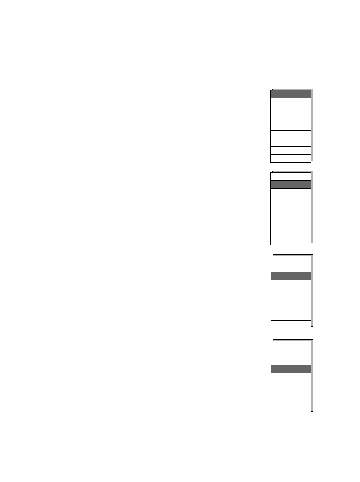
6 Operation
Buzzer
PS endflow
Buzzer
PS endflow
Buzzer
PS endflow
Buzzer
PS endflow
I-flow
PS ramp
Trigg.
Byflow
Available in the ventilation mode SIMV-VC.
This allows the setting of the inspiratory flow in the
range of 2 to 99.9 L/min, depending on the timing
settings of the mode.
This setting is identical to the I-flow soft key setting
in the ventilation mode “VCV”.
Available in the ventilation modes: SIMV-VC,
Bi-Level, CPAP/PSV and CPAP/Apnea.
This setting adjusts the rate the pressure increases
from the PEEP pressure to the PS pressure in the
range of 0.1 to 0.5 secs. This setting is similar to
the Bi-Level ramp soft key setting.
The default setting is 0.2 secs.
Available in the following ventilation modes: SIMVVC, Bi-Level, CPAP/PSV and CPAP/Apnea.
This allows the setting of the flow trigger in the
range of 0.5 to 20 L/min. The flow trigger value is
the amount of flow the patient needs to remove
from the breathing circuit by their inspiratory effort
to trigger the ventilator.
The default setting is 3.0 L/min.
Available in the ventilation modes: VCV, SIMV-VC,
Bi-Level, CPAP/PSV and CPAP/Apnea.
The setting of the Byflow is from 3.0 to 30 L/min.
The Byflow permanently flows through the
breathing circuit providing a “flow reservoir” for a
spontaneous breathing patient. Increasing the
Byflow increases the flow reservoir, but also
increases the pressure drop within the breathing
circuit. The default setting is 3.0 L/min.
I-flow
PS ramp
Trigg.
ByFlow
Time window
I-flow
PS ramp
Trigg.
ByFlow
Time window
I-flow
PS ramp
Trigg.
ByFlow
Time window
I-flow
PS ramp
Trigg.
ByFlow
Time window
10.0 L/m
0.20 s
3.0 L/m
3.0 L/m
Previous menu
Exit
10.0 L/m
0.20 s
3.0 L/m
3.0 L/m
Previous menu
Exit
10.0 L/m
0.20 s
3.0 L/m
3.0 L/m
Previous menu
Exit
10.0 L/m
0.20 s
3.0 L/m
3.0 L/m
Previous menu
Exit
60%
25%
100%
60%
25%
100%
60%
25%
100%
60%
25%
100%
6-28
URM Centiva/5, CM-920041, rev. 2.22
 Loading...