

Page 1

Datex-Ohmeda
AS/3 Compact Monitor, CS/3 Compact Monitor
Technical Reference Manual
Datex-Ohmeda Inc.
3 Highwood Drive
Tewksbury, MA 01876
Tel. (978) 640-0460 Fax (978) 640-0469
www.us.datex-ohmeda.com
All specifications are subject to change without notice.
Document No. 896623
February 2000
Datex-Ohmeda Division,
Instrumentarium Corp.
P.O. Box 900, FIN-00031
DATEX-OHMEDA, FINLAND
Tel. +358 10 394 11 Fax +358 9 146 3310
www.datex-ohmeda.com
Instrumentarium Corp. All rights reserved.
Page 2

NOTICE
Intended purposes
The Datex-Ohmeda AS/3 Compact Monitor is a multiparameter patient monitor intended for the
physiological monitoring of hospitalized patients. It is indicated for monitoring anesthetized patient’s
relaxation, hemodynamic, ventilation, gas exchange, regional perfusion and neurophysiological parameters.
The system is indicated for use by qualified medical personnel only.
The Datex-Ohmeda CS/3 Compact Monitor, CMC, is a multiparameter patient monitor intended for the
physiological monitoring of hospitalized patients. It is indicated for monitoring the patient’s hemodynamic,
ventilation, gas exchange, regional perfusion and central nervous system. The system is indicated for use by
qualified medical personnel only.
The Datex-Ohmeda CS/3 Compact Monitor with S-ICU99/A software is intended for multiparameter patient
monitoring. The monitor is indicated for monitoring of hemodynamic (including arrhythmia and ST-segment
analysis), respiratory, ventilatory, gastrointestinal/regional perfusion and neurophysiological status of all
hospital patients. The system is indicated for use by qualified medical personnel only.
Classifications
In accordance with IEC 60601-1:
Class I and internal powered equipment- the type of protection against electric shock.
Type BF or CF equipment. The degree of protection against electric shock is indicated by a symbol on the
parameter panel beside each connector.
Equipment is not suitable for use in the presence of a flammable anesthetic mixture with air or with oxygen or
nitrous oxide.
Continuous operation according to the mode of operation.
In accordance with IEC 60529:
Degree of protection against the harmful ingress of water as detailed in the IEC 60529: IPX1
In accordance with EU Medical Device Directive: IIb
Responsibility of the manufacturer
Datex-Ohmeda Division, Instrumentarium Corp. is responsible for the safety, reliability and performance of
the equipment only if:
− assembly, operations, extensions, readjustments, modifications, service and repairs are carried out
by personnel authorized by Datex-Ohmeda.
− electrical installation complies with appropriate requirements.
− the equipment is used in accordance with the User’s Guide and serviced and maintained in
accordance with the Technical Reference Manual.
Storage and Transport
For allowed storage and transport conditions refer to the documentation delivered with the monitor.
Trademarks
Datex®, Ohmeda®, and other trademarks AS/3, CS/3, D-lite, Pedi-lite, D-fend, D-fend+, MemCard,
ComWheel, EarSat, FingerSat, FlexSat, PatientO2, Patient Spirometry and Tonometrics are property of
Instrumentarium Corp. or its subsidiaries. All other product and company names are property of their
respective owners.
© Instrumentarium Corp. All rights reserved.
Page 3

Master table of contents
Datex-Ohmeda AS/3TM Compact Monitor and CS/3TM Compact Monitor
Technical Reference Manual, 896 623
#
Folder
Document No. Updated Updated Description
1(2), PART I, General Service Guide
896 623
896674
8001068
888737-2
895156-2
896 620-1
896 619
896 621
896 622-1
Introduction, System description, Installation, Interfacing, Functional check, General troubleshooting
Planned Maintenance Instructions
PART II, Product Service Guide
AS/3 CM Frames; F-CM, F-CMREC
CS/3 CMC Frames; F-CMC, F-CMCREC
CPU Boards; B-CMCPU4, B-CPU3, B-CPU2
Software cards and cartridges
Upinet Board,B-UPINET
MRI Shield, N-MRI
MRI Multiparameter NES Module, M-MRI
Folder #2(2), PART II, Product Service Guide (continues)
Hemodynamic Modules,
M-NE12STPR, M-NE12STR, M-NE12TPR, M-NESTPR, M-NESTR, M-NETPR, M-ESTPR, M-ESTR, M-ETPR
Compact Airway Modules, M-CAiOVX, M-CAiOV,M-CAiO, M-COVX, M-COV, M-CO, M-C
Tonometry Module, M-TONO
EEG Module, M-EEG and EEG Headbox, N-EEG
1
2
1
2
3
1
2
3
4
889 881-5
885 935-7
893 224-3
885 936-6
885 937-6
885 940-7
887 780-5
893 780-3
885 939-6
893 779-2
885 941-6
Cardiac Output Modules, M-COP and M-COPSv
Pressure Module, M-P, Pressure Temp Module, M-PT
Dual Pressure Module, M-PP
NIBP Module, M-NIBP
Recorder Module, M-REC
Nellcor Compatible Saturation Module, M-NSAT
NeuroMuscular Transmission Module, M-NMT
Anesthesia Keyboard, K-ARK, Keyboard Interface Board, B-ARK and ARK Barcode Reader, N-SCAN
Memory Module, M-MEM, Memory Board, B-CMMEM
Interface Module, M-INT
Network Board, B-NET
5
6
7
8
9
10
11
12
13
14
15
Document No. 896623
Page 4

Page 5

Table of contents
TABLE OF CONTENTS
AS/3 Compact Monitor, CS/3 Compact Monitor
TABLE OF CONTENTS i
TABLE OF FIGURES ii
1 INTRODUCTION 1
1.1 Notes to the reader ....................................................................................................................................2
1.1.1 Related Documentation.....................................................................................................................2
1.1.2 Conventions used..............................................................................................................................3
1.2 Safety Precautions.....................................................................................................................................6
1.2.1 Warnings ..........................................................................................................................................6
1.2.2 Cautions ...........................................................................................................................................7
2 SYSTEM DESCRIPTION 9
2.1 Introduction...............................................................................................................................................9
2.2 Bus structure .............................................................................................................................................9
2.3 Distributed processing .............................................................................................................................10
2.4 Module communication ...........................................................................................................................11
2.5 Software loading......................................................................................................................................12
2.6 Parameter modules .................................................................................................................................12
3 SYSTEM INSTALLATION 14
3.1 Unpacking instructions.............................................................................................................................14
3.2 Choosing location....................................................................................................................................14
3.3 Assembling the AS/3, CS/3 Compact Monitor Frame................................................................................14
3.3.1 Compact Monitor connections .........................................................................................................15
3.3.2 Rear panel connectors.....................................................................................................................16
3.3.3 Connection to mains........................................................................................................................17
3.3.4 Connection to Network ....................................................................................................................17
3.3.5 Inserting the parameter modules......................................................................................................17
3.3.6 Replacing the CPU Board, B-CMCPU4..............................................................................................18
3.3.7 Performing Factory Reset.................................................................................................................19
3.3.8 Replacing the Software Cartridge of B-CPU2/3.................................................................................20
3.3.9 Replacing the CPU Board, B-CPU2/3...............................................................................................21
3.4 AS/3 Memory Board, B-CMMEM Installation (w/ B-CPU2/3).....................................................................23
3.5 AS/3 Memory Board, B-CMMEM Installation (w/ B-CMCPU4)....................................................................26
3.6 Network Board, B-NET Installation (w/ B-CPU2/3) ....................................................................................29
3.7 Network Board, B-CMNET Installation (w/ B-CMCPU4) ..............................................................................32
3.8 AS/3 UPINET Board, B-UPINET Installation (w/ B-CPU2/3)........................................................................34
3.9 AS/3 UPINET Board, B-UPINET Installation (w/ B-CMCPU4).......................................................................37
3.10 Compact Airway Modules, M-XXXX..........................................................................................................39
3.10.1 Sample Gas Exhaust .....................................................................................................................39
3.10.2 Scavenging Through Reservoir .......................................................................................................40
3.10.3 Scavenging Through Direct Connection ..........................................................................................40
3.10.4 Returning Gas to Patient Circuit......................................................................................................41
3.11 AS/3 Anesthesia Keyboard, K-ARK.........................................................................................................41
3.12 Remote Controller, K-REMCO .................................................................................................................41
3.13 Bar Code Reader ...................................................................................................................................42
Document No. 896623
i
Page 6

Datex-Ohmeda AS/3 CM and CS/3 CMC
3.13.1 Connection to the Compact Monitor...............................................................................................42
3.13.2 Different Configurations ................................................................................................................42
3.14 Troubleshooting .................................................................................................................................... 44
4 INTERFACING 45
4.1 Interfacing Monitors via UPI Board, B-UPI .................................................................................................46
4.1.1 Interconnection Datex-Ohmeda Monitors .........................................................................................46
4.1.2 Setting the Interfacing Parameters................................................................................................... 47
4.1.3 Setting the Interfacing Parameters for the Compact Monitor.............................................................. 47
4.2 Interfacing with Datex-Ohmeda Monitors via UPINET Board, B-UPINET .......................................................47
4.3 Interfacing Monitors via M-INT..................................................................................................................48
4.3.1 Connection to Datex-Ohmeda Monitors............................................................................................48
4.3.2 Connection to Critikon Dinamap 1846SX, Abbott Oximetrix 3 and Baxter Explorer ..............................49
4.3.3 Connection to Baxter Vigilance ........................................................................................................49
4.3.4 Connection to Nellcor N-100 and N-1000........................................................................................49
4.3.5 Connection to Nellcor N-200 ...........................................................................................................49
4.4 Interfacing Datex-OhmedaAS/3 Anesthesia Delivery Unit.......................................................................... 49
4.5 Interfacing Dräger Cicero and Cato ...........................................................................................................50
4.6 Interfacing a printer .................................................................................................................................50
4.7 Interfacing a computer.............................................................................................................................50
4.8 UPI Board Output Signals.........................................................................................................................51
4.8.1 Digital Outputs................................................................................................................................ 51
4.8.2 Analog Outputs ...............................................................................................................................52
4.8.3 Setting the Analog Output Signals....................................................................................................53
4.9 Pressure Temp Module, M-PT Output Signals ............................................................................................54
4.9.1 Analog Outputs ...............................................................................................................................54
5 FUNCTIONAL CHECK 55
5.1 Recommended tools ...............................................................................................................................55
5.2 Visual inspection/preparation..................................................................................................................55
5.3 Functional Inspection ..............................................................................................................................58
6 GENERAL TROUBLESHOOTING 74
APPENDIX A 75
FUNCTIONAL CHECK FORM A-1
TABLE OF FIGURES
Figure 1 AS/3, CS/3 Compact Monitor ..................................................................................................................1
Figure 2 General Structure of AS/3 and CS/3 System.............................................................................................9
Figure 3 Distributed Processing in AS/3 and CS/3 System ...................................................................................10
Figure 4 Principle of UPI operation .......................................................................................................................11
Figure 5 Software loading....................................................................................................................................12
Figure 6 General structure of parameter modules .................................................................................................13
Figure 7 AS/3 Compact Monitor Connections....................................................................................................... 15
ii
Document No. 896623
Page 7

Table of contents
Figure 8 Rear Panel with Memory, CPU and UPINET Boards ...................................................................................16
Figure 9 Rear Panel with NET, CPU and UPI Boards. NET and UPI Boards can be replaced by UPINET board.............16
Figure 10- Datex-Ohmeda Compact Airway Module ..............................................................................................39
Figure 11 Scavenging through Ventilator Reservoir................................................................................................40
Figure 12 Connection Directly to a Scavenging System .........................................................................................40
Figure 13 Sample Gas Return to Patient Circuit in ADU..........................................................................................41
Figure 14 Bar Code Reader connected to the Compact Monitor .............................................................................42
Figure 15 Monitor General Troubleshooting Flowchart ...........................................................................................74
Document No. 896623
iii
Page 8

Datex-Ohmeda AS/3 CM and CS/3 CMC
iv
Document No. 896623
Page 9

1 INTRODUCTION
Datex-Ohmeda AS/3 Compact Monitor is a cardiac and respiratory monitoring device used during
anesthesia, recovery and short transports.
Datex-Ohmeda CS/3 Compact Monitor is designed for monitoring in intensive care units.
The monitor consists of the CM frame and modules. There are single and double width modules
containing one or more parameters. The modules can be removed and inserted during operation.
The CM frame is equipped with a battery, and also a built-in recorder is available. AS/3 Anesthesia
Keyboard, K-ARK is available for AS/3 Compact Monitor.
General Service Guide
1
Figure 1 AS/3, CS/3 Compact Monitor
(1) CM Frame
(2) Printer
(3) Remote Controller, K-REMCO
2
3
Document No. 896 623
1
Page 10

Datex-Ohmeda AS/3 Compact Monitor, CS/3 Compact Monitor
1.1 Notes to the reader
This technical reference manual is intended for service personnel and engineers who will perform
service and maintenance procedures on Datex-OhmedaAS/3 Compact Monitor and DatexOhmeda CS/3 Compact Monitor.
This technical reference manual is divided into two parts:
• The Part I gives to the reader overview of the AS/3 Compact Monitor and CS/3 Compact
Monitor. This part of the manual contains also the information you need to unpack, install
and test the monitors. Read the manual through and make sure that you understand the
procedures described before installation of the monitor. To avoid risks concerning safety or
health, strictly observe the warning indications. If you need any assistance concerning the
installation, please do not hesitate to contact your authorized distributor.
• The Part II gives detailed descriptions of each component of Compact Monitor.
The manufacturer reserves the right to make changes in product specifications without prior notice.
The information in this manual is believed to be accurate and reliable; however, the manufacturer
assumes no responsibility for its use.
Datex-Ohmeda assumes no responsibility for the use or reliability of its software on equipment that
is not furnished by Datex-Ohmeda.
1.1.1 Related Documentation
AS/3 Compact Monitor
More information about the clinical aspects and technical background:
AS/3 Compact Monitor, User’s Guide
AS/3 Compact Monitor, User’s Reference Manual
Default configuration options: Default Configuration Worksheet
Circuit diagrams, component lay-out pictures, etc.: Schematic Diagrams
More information about other devices closely related to the Compact Monitor:
Information Center, User’s Reference Manual
AS/3 Record Keeper, User’s Reference Manual
CS/3 Compact Monitor
More information about the clinical aspects and technical background:
CS/3 Compact Monitor, User’s Guide
CS/3 Compact Monitor, User’s Reference Manual
Default configuration options: Default Configuration Worksheet
Circuit diagrams, component lay-out pictures, etc.: Schematic Diagrams
2
Document No. 896 623
More information about other devices closely related to the Compact Monitor:
Information Center, User’s Reference Manual
CS/3 Arrhythmia Workstation, User’s Reference Manual
Page 11

1.1.2 Conventions used
Throughout this manual, the following conventions are used to distinguish procedures or elements
of text:
General Service Guide
?
Sign the performed procedure in the check list.
To help you find and interpret information easily, the manual uses consistent text formats for
certain text types:
Hard Keys Names of the hard keys on the Remote Controller, Command Board and modules are written in the
following way:
Menu Items Menu items are written in bold italic typeface, for example Location.
‘Messages’ Messages (alarm messages, informative messages) displayed on the screen are written inside
single quotes, for example ‘Learning’.
Chapters When referring to different sections in this manual, section names are written in italic typeface and
enclosed in double quotes, for example “Cleaning and Care”.
WARNING Warnings are written in bold D-O Sans typeface. The font size is 13 points. The
word warning itself is written in capitals.
CAUTION The font size is 13 points. The word caution itself is written in capitals.
NOTE: Notes are written like this using Bodytext.
Symbols on transport packaging
Cancel.
The contents of the transport package are fragile and have to be handled with care.
This symbol indicates the correct upright position of the transport package.
The transport package must be kept in a dry environment.
This symbol is to indicate the temperature limitations within which the transport package should be
kept and handled.
Symbols on equipment
Ni-Cd
This battery contains Ni-Cd and in case of disposal, must be separated from other
waste according to local regulations.
3
Document No. 896 623
Page 12

Datex-Ohmeda AS/3 Compact Monitor, CS/3 Compact Monitor
This battery contains Ni-Cd and it can be recycled.
Ni-Cd
Dangerous voltage
When using the ARK Barcode Reader, N-SCAN, do not stare into beam. The N-SCAN
Barcode Reader is a Class 2 laser product.
Attention, consult accompanying documents.
When displayed beside the O
value, indicates that FiO2 low alarm limit is set below 21
2
%.
When displayed next to the HR value, indicates that the pacer is set on R or a wide QRS
is selected.
On the Interface Module M-INT, indicates that it is for connecting external devices. Do
not connect patient cables to the module.
On the rear panel of the monitor indicates the following warnings and cautions:
• Electric shock hazard. Do not open the cover or the back.
Refer servicing to qualified personnel.
For continued protection against fire hazard, replace only with same type
•
and rating of fuse.
• Disconnect power supply before servicing.
Type BF (IEC-601-1) protection against electric shock
Type BF (IEC-601-1) defibrillator-proof protection against electric shock
Type CF (IEC-601-1) protection against
electric shock
Type CF (IEC-601-1) defibrillator-proof protection against electric shock
Other Symbols
4
Document No. 896 623
Gas outlet (in airway gas models only)
Ethernet connectors
When displayed on the upper left corner of the screen, indicates that the alarms
are silenced. When in the menu or digit fields, indicates that the alarm source has
been turned off.
Equipotentiality. Monitor can be connected to potential equalization conductor.
Page 13

Alternating current
Fuse
General Service Guide
SN, S/N
Serial Number
Sub menu. Selecting an alternative with this symbol in a menu opens a new menu.
The monitor is connected to the Datex-Ohmeda Network.
Data card (green) and/or the Menu card (white) is inserted.
Indicates the beats detected.
Respiration rate is measured using impedance respiration measurement.
Document No. 896 623
5
Page 14

Datex-Ohmeda AS/3 Compact Monitor, CS/3 Compact Monitor
1.2 Safety Precautions
1.2.1 Warnings
WARNING A WARNING indicates a situation in which the user or the patient may be in
danger of injury or death
Power Connection
• Before connecting the power cord to the mains outlet, check that the local voltage and
frequency rating corresponds with the rating stated on the device plate on the rear panel of
monitor frame.
• Connect the monitor to a three-wire, grounded, hospital grade receptacle. Do not remove
the grounding prong from the power plug.
• Use intact power cord. Replace the cord if it is cracked, frayed, broken or otherwise
damaged.
• Do not apply tension to the power cord. The cord may get broken.
• Do not use extension cords or adapters of any type.
External Connection
• Do not connect any other external devices to the monitor than those specified by Datex-
Fuse Replacement
• Replace the fuse with a fuse of the same type and with the same rating.
Explosion Hazard
• Do not use the monitor in the presence of flammable anesthetics.
Patient Safety
• Do not perform any testing or maintenance on the monitor while it is being used on a
• Use only cables and accessories approved by Datex-Ohmeda. Do not modify them. Other
Ohmeda.
patient.
cables and accessories may damage the monitor or interfere with measurement.
6
Document No. 896 623
• PACEMAKER PATIENTS: The impedance respiration measurement may cause rate changes
in Minute Ventilation Rate Responsive Pacemakers. Set the pacemaker rate responsive
mode off or turn the impedance respiration measurement off on the monitor.
Page 15

General Service Guide
Cleaning and Service
• Only trained personnel with proper tools and test equipment should perform the tests and
repairs described in this manual. Unauthorized service may void the monitor warranty.
• Switch the power off and unplug the power cord before cleaning or service. Get rid of
moisture completely before reconnecting it to the mains outlet.
• Do not touch any exposed wire or conductive surface while covers are off and the monitor is
energized. The voltages present can cause injury or death.
• Perform electrical safety check and leakage current test to the monitor always after service.
1.2.2 Cautions
CAUTION A CAUTION indicates a condition that may lead to equipment damage or
malfunction.
Installation
• Leave space behind the monitor to allow proper ventilation.
Before Use
• Allow two minutes for warm-up and note any error messages or deviations from normal
operation.
• Clean side panel fan dust filter once a month or whenever necessary.
Autoclaving and Sterilizing
• Do not autoclave any part of the monitor.
• Do not gas sterilize the modules.
Cleaning and Service
• Do not use ammonia-, phenol-, or acetone-based cleaners. These cleaners may damage
the monitor surface.
• Do not immerse the monitor in any liquid. Do not allow liquid to enter the monitor or into
modules.
• Electrostatic discharge through the PC boards may damage the components. Before
replacing PC boards, wear a static control wrist strap. Handle all PC boards by their nonconductive edges and use anti-static containers when transporting them.
• Do not break or bypass the patient isolation barrier when testing PC boards.
7
Document No. 896 623
Page 16

Datex-Ohmeda AS/3 Compact Monitor, CS/3 Compact Monitor
Special Components
• There are special components used in this monitor which are vital to assure reliability and
safety. Datex-Ohmeda assumes no responsibility for damage if replacement components
not approved by Datex-Ohmeda are used.
• There is a lithium battery on the CPU board. Discard broken IC containing the battery according
to local regulations.
Batteries
The battery package of the power supply unit in this device contains NiCd which is hazardous to
environment and thus the battery needs to be disposed of carefully according to local regulations.
To replace the batteries safely, please refer to the instructions further on in this manual.
• Do not short-circuit the battery terminals, short-circuiting the battery may produce a very
high current, which damages the battery.
• Do not dispose of the battery into open flame, nor put the battery near fire, as it may
explode.
• Do not disassemble the battery. It contains electrolyte, which may damage clothing or
cause injury to skin or eyes. If exposed to electrolyte, wash the injured area with plenty of
water and contact a doctor.
See also the chapter “Symbols”.
Storage and Transport
Do not store or transport the monitor outside the specified temperature and pressure range:
Temperature -10...+50 °C /14...122 °F
Ambient pressure 660...1060 hPa/500...800 mmHg/
Humidity 0...85 % non-condensing
Discard
Discard the device and parts thereof according to local regulations. Do not discard to the nature.
The manufacturer accepts no responsibility for any modifications made to the monitor outside the
factory.
660...1060 mbar
8
Document No. 896 623
Page 17

2 SYSTEM DESCRIPTION
2.1 Introduction
Datex-OhmedaAS/3 and CS/3 monitors builds up to freely configurable modular system. The
architecture is designed to enable different module combinations so that the user is able to get the
desirable parameter and feature set. The modular approach makes it possible to add new features
when they are needed.
2.2 Bus structure
The operation of Datex-OhmedaAS/3 and CS/3 products is based on two communication
channels, the CPU bus and the module bus. All boards connected to the CPU bus as well as the
parameter modules attached to the module bus receive their power from the same power supply,
which is an integral part of the frame.
General Service Guide
UPI /
UPINET
CPU BUS
MODULE BUS
Figure 2 General Structure of AS/3 and CS/3 System
The CPU bus is a parallel communication channel used only for internal data transfer between the
boards connected to one frame. It is based on the ISA bus used in the IBM PC computers. Data is
transferred on this 16 bits wide bus using the CPU clock frequency.
The module bus is used to connect the parameter modules to the frame. It based on the widely
used industry standard RS-485, which uses differential serial method to transfer the data. This
type of bus is quite robust and it allows the modules to be attached or detached when the power is
on.
The RS-485 type serial communication supports so called multidrop or party line connections. This
means that all modules connected to module bus are using the same two physical wires for
communication purposes. The advantage is, that all the module bus connectors are identical and
the modules can be connected to any order and position.
CPU
Parameter
Module
Display
Controller
Parameter
Module
Power
Supply
Module bus is using 500 kbps data transfer rate and it can be used for longer distances than the
CPU bus, e.g. for external-frame connections.
Document No. 896 623
9
Page 18

Datex-Ohmeda AS/3 Compact Monitor, CS/3 Compact Monitor
2.3 Distributed processing
A system put together from AS/3 and CS/3 products is a multiprocessor system. All the modules
have their own microprocessor and they are doing the low-level functions such as module key
control, waveform filtering, pneumatic control, etc. At the same time the main CPU is doing higher
level tasks, e.g. trending and alarm control. While modules and CPU are doing their job, the UPI
processor takes care of all functions needed to transfer the data between modules and CPU. And
at the same time the processor on display control board is doing pixel calculations for graphics.
This kind of parallel processing gives one major advantage to centralized processing. Each time
new modules or boards are added to the system, the processing power is also increased. As a
result the system is not slowing down when new features are added.
Module
RAM
UPI or UPINET
Dual-port RAM
Display Control
Figure 3 Distributed Processing in AS/3 and CS/3 System
CPU
System memory
Board
Display memor y
10
Document No. 896 623
Page 19

2.4 Module communication
A
s
The communication master controlling the data transfer between CPU bus and module bus is
called UPI (Universal Peripheral Interface) board. It sends information or questions to each module
100 times per second, and if the module is present it replies to each question immediately by
sending a data package back to UPI board. This communication protocol ensures that each
module receives and sends information every 10 ms, the package length depends on the module
type. If the module does not respond, the UPI presumes that the module is not connected.
Each module type has a unique name, which UPI uses to address its messages. If there are two
modules of the same type, they both answer at the same time. This results an error and thus two
similar modules are not allowed in one frame.
General Service Guide
UPI Board
CPU Bus
Module Bus
Dual-port
RAM
Microcontroller
Figure 4 Principle of UPI operation
The microprocessor on the UPI board collects all information coming from the modules into a dualport RAM. This memory is located on UPI board and it is mapped directly to the address space of
the main CPU. The main CPU is thus reading information from it's own memory and UPI guarantees
that the data is up to date. This operation works also to the other direction, when CPU is filling the
dual port RAM with data and UPIs’ microprocessor is distributing it to the modules.
S/3 Bu
11
Document No. 896 623
Page 20

Datex-Ohmeda AS/3 Compact Monitor, CS/3 Compact Monitor
2.5 Software loading
The Software Cartridge attached to the B-CPU2/3 board contains the program for the CPU board
as well as for some other boards attached to the CPU bus. When the system is turned on, all
processors load their part of the software from the cartridge and after that start to execute their
program.
The CPU Board, B-CMCPU4 contains no external software cartridge. The softwares are always
loaded on the B-CMCPU4 boards already at the factory. For service procedures B-CMCPU4 boards
has a PC card drive, through which the software is loaded permanently on the board from the
software card.
w/ B-CPU2/3 or w/ B-CMCPU4
Software
Cartridge
UPI OR UPINET
Board
Program
Memory
CPU
Board
Program
Memory
Software
Card
Display
Controller
Board
Program
Memory
Figure 5 Software loading
2.6 Parameter modules
The detailed structure of the parameter modules depends on the specific needs for each individual
parameter. Some common parts can be found inside the modules, however. The electronics inside
the module is usually divided into isolated (floating) and non-isolated sections. Typically the nonisolated part consists only buffers needed to interface the module to module bus, the rest of the
electronics can be found from the isolated side. This includes the microcontroller together with
memory components, the front end analog electronics (amplifiers, etc.) and peripheral drivers to
control LEDs, sensors, valves and pumps.
CPU BUS
12
Document No. 896 623
Page 21

General Service Guide
Module
keys
Patient
Analog
electronics
Peripheral
drivers
A/D
converter
RAM
EEPROM
Figure 6 General structure of parameter modules
+5V
±12V
CPU
Isolation
transformer
P
a
t
i
e
n
t
i
s
o
l
a
t
i
o
n
Opto
isolation
Power
+15V
Reset
Data
RS485
drivers
M
o
d
u
l
e
B
u
s
13
Document No. 896 623
Page 22

Datex-Ohmeda AS/3 Compact Monitor, CS/3 Compact Monitor
3 SYSTEM INSTALLATION
3.1 Unpacking instructions
1. Confirm that the packing box is undamaged. If the box is damaged, contact the shipper.
2. Open the top of the box and carefully unpack all components.
3. Confirm that all components are undamaged. If any of the components is damaged,
contact the shipper.
4. Confirm that all components are included. If any of the components is excluded, contact
your Datex-Ohmeda distributor.
3.2 Choosing location
Consider the following aspects:
• Lighting
• Space
• Connections
• Electromagnetic and radio frequency interference
• Atmosphere
3.3 Assembling the AS/3, CS/3 Compact Monitor Frame
Mounting of the Compact Monitor to the Compact Monitor Bed Mount or Wall Mount is described in
a separate instruction sheet delivered with the mount.
14
Document No. 896 623
Page 23

3.3.1 Compact Monitor connections
1
2
General Service Guide
9
3
4
5
6
8
7
Figure 7 AS/3 Compact Monitor Connections
(1) Dust filter
(2) Recorder (optional)
(3) Connector for Remote Controller, Anesthesia Keyboard (K-ARK) and Bar Code Reader
(4) Potential equalization
(5) Mains power inlet
(6) Network connectors on B-NET/B-CMNET (optional)
(7) Device plate with voltage information
(8) Network connectors on B-UPINET/B-UPI (optional)
(9) Insertion slots for memory cards (optional)
15
Document No. 896 623
Page 24

Datex-Ohmeda AS/3 Compact Monitor, CS/3 Compact Monitor
3.3.2 Rear panel connectors
1
2
3
Figure 8 Rear Panel with Memory, CPU and UPINET Boards
(1) Software Cartridge, on CPU board, B-CPU2 or B-CPU3,
or Software Card drive and lid for back plate on B-CMCPU4,
connector on B-CMCPU4 is reserved for future use (not in figure).
(2) Network connector
(3) Network identification plug connector
(4) Serial communication connector
1
2
3
4
5
Figure 9 Rear Panel with NET, CPU and UPI Boards. NET and UPI Boards can be
replaced by UPINET board.
(1) Network identification plug connector
4
6
(2) Network connector
(3) Ethernet status LEDs
(4) Software Cartridge, on CPU board, B-CPU2 or B-CPU3,
or Software Card drive and lid for back plate on B-CMCPU4,
connector on B-CMCPU4 is reserved for future use (not in figure).
(5) Serial communication connector
(6) Parallel printer port, analogue & digital input/output connector
CAUTION Turn the power off before making any rear panel connections.
NOTE: Your monitor configuration may not include all circuit boards listed above.
16
Document No. 896 623
Page 25

General Service Guide
3.3.3 Connection to mains
Connect the power cord to the mains power inlet on the side of the monitor and to the wall socket.
WARNING The power cord may only be connected to a three-wire, grounded, hospital grade
receptacle.
3.3.4 Connection to Network
To connect your monitor to Datex-Ohmeda Network, make sure you have a network board B-NET or
B-UPINET installed.
Use the Monitor-Network cable to connect the monitor to the network.
1. Make sure that the power is turned off.
2. Connect the one of RJ-45 connectors to the connector and the Identification Plug to X2
connector on the network board.
3. Connect the other RJ-45 connector to the corresponding connector on the wallbox.
4. Turn on the power. Confirm that the network symbol and 'Connected to Network' message
are displayed on the upper part of the screen.
NOTE: The network symbol will not be displayed if the battery symbol is displayed on the upper part
of the screen.
3.3.5 Inserting the parameter modules
Insert each plug-in parameter module into a module slot. Firmly press the module in position.
NOTE: Do not use two or more modules with identical functions in the monitor. Take special care of
this when using the extension frame.
Modules with identical functions are:
• Haemodynamic multiparameter modules: M-ESTPR, M-ETPR, M-ESTR, M-NESTPR, M-
NETPR, M-NESTR, M-NE12STPR, M-NE12TPR and M-NE12STR
• Pressure Modules: M-P, Pressure Temp Module, M-PT
• Cardiac Output Modules: M-COP and M-COPSv
• NIBP Modules: M-NIBP, M-NESTPR, M-NETPR, M-NESTR, M-NE12STPR, M-NE12TPR and
M-NE12STR
• Airway Modules: M-C, M-CO, M-COV, M-CAiOV, M-CAiO and M-CAiOVx
• The Recorder Module, M-REC and the built-in recorders in F-CMREC or F-CMCREC may not
be used simultaneously.
17
Document No. 896 623
Page 26

Datex-Ohmeda AS/3 Compact Monitor, CS/3 Compact Monitor
3.3.6 Replacing the CPU Board, B-CMCPU4
In case of service procedures (empty B-CMCPU4 and service software on PCMCIA card) refer the
slot of CM Frame, CPUs and Softwares; Part II/1.
1. Make sure that the power is turned off on the Compact Monitor and unplug the power cord.
Press and hold the service reset button on the rear panel for at least five seconds until the
service reset indicator LED is switched off.
2. Unscrew the six screws holding the back plate in position and remove the plate.
WARNING The Compact Monitor is always energized by the internal battery. Do not touch
any exposured wiring or conductive surface with metallic object while the back
plate is off or electric failure may result.
CAUTION The Compact Monitor is always energized by the internal battery. A short circuit may
cause internal damage.
3. Before you can remove the B-CMCPU4 board you have to remove boards next to it (B-
UPI/B-UPINET and B-NET/B-CMMEM). Refer instructions in this same chapter.
4. Unscrew the screws holding the B-CMCPU4 board in position and remove the board.
18
Document No. 896 623
Page 27

General Service Guide
5. Remove the CPU board from the protective anti static packaging. Always hold the board by
the edges and wear a wrist grounding strap.
CAUTION The CPU Board comprises sensitive integrated circuits that can be damaged by an
electrostatic discharge. Careful handling of the board is therefore essential.
6. Insert the new CPU Board into the empty slot and firmly press the board in position.
7. Replace PC boards removed earlier and secure the boards.
8. Attach the back plate removed earlier.
9. Reconnect the Power Cord and turn the power on.
10. Perform factory reset.
3.3.7 Performing Factory Reset
NOTE: The factory reset is necessary after replacing software and after replacing CPU board.
NOTE: The factory reset will restore all your customized defaults, including language selection, to
factory defaults.
1. Press the
2. Select Install/Service and password (16-4-34).
3. Select Service and password (26-23-8).
4. Select Set/ Test and perform factory reset.
Monitor Setup key.
19
Document No. 896 623
Page 28

Datex-Ohmeda AS/3 Compact Monitor, CS/3 Compact Monitor
3.3.8 Replacing the Software Cartridge of B-CPU2/3
NOTE: All user settings will be lost after replacing the software cartridge.
1. Make sure that the power is turned off on the Compact Monitor and unplug the power cord.
Press and hold the service reset button on the rear panel for at least five seconds until the
service reset indicator LED is switched off.
2. Unscrew the two screws holding the software cartridge in position and remove the cartridge.
20
Document No. 896 623
3. Insert the new software cartridge into the empty slot and firmly press the cartridge in
position. Secure the cartridge (two screws).
4. Reconnect the power cord.
5. Perform factory reset.
NOTE: After changing the software cartridge the start-up time is considerably longer when the
monitor is started for the first time.
Page 29

3.3.9 Replacing the CPU Board, B-CPU2/3
1. Make sure that the power is turned off on the Compact Monitor and unplug the power cord.
Press and hold the service reset button on the rear panel for at least five seconds until the
service reset indicator LED is switched off.
2. Unscrew the six screws holding the back plate in position and remove the plate.
General Service Guide
WARNING The Compact Monitor is always energized by the internal battery. Do not touch
any exposured wiring or conductive surface with metallic object while the back
plate is off or electric failure may result.
CAUTION The Compact Monitor is always energized by the internal battery. A short circuit may
cause internal damage.
21
Document No. 896 623
Page 30

Datex-Ohmeda AS/3 Compact Monitor, CS/3 Compact Monitor
3. Remove the software cartridge.
4. Unscrew the screw holding the CPU Board in position and remove the board.
5. Remove the CPU Board from the protective anti static packaging. Always hold the board by
the edges and wear a wrist grounding strap.
CAUTION The CPU Board comprises sensitive integrated circuits that can be damaged by an
electrostatic discharge. Careful handling of the board is therefore essential.
6. Remove the EMC plate from the CPU Board.
7. Insert the new CPU Board into the empty slot and firmly press the board in position. Secure
the new board.
8. Replace the Software Cartridge and secure the cartridge with the two screws removed from
the cartridge earlier.
9. Replace the back plate and secure the plate with the six screws removed from the plate
earlier.
10. Reconnect the Power Cord.
11. Perform Factory Reset.
22
Document No. 896 623
Page 31
General Service Guide
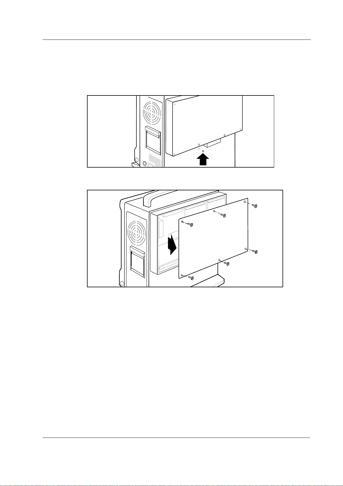
3.4 AS/3 Memory Board, B-CMMEM Installation (w/ B-CPU2/3)
1. Make sure that the power is turned off on the Compact Monitor and unplug the Power Cord.
Press and hold the Service Reset button on the rear panel for at least five seconds until the
service reset indicator LED is switched off.
2. Unscrew the six screws holding the back plate in position and remove the plate.
WARNING The Compact Monitor is always energized by the internal battery. Do not touch
any exposured wiring or conductive surface with metallic object while the back
plate is off or electric failure may result.
CAUTION The Compact Monitor is always energized by the internal battery. A short circuit may
cause internal damage.
23
Document No. 896 623
Page 32

Datex-Ohmeda AS/3 Compact Monitor, CS/3 Compact Monitor
3. Unscrew the two nuts holding the side plates in position and remove the plates. Put the
memory card collar in the place of the side plates.
1
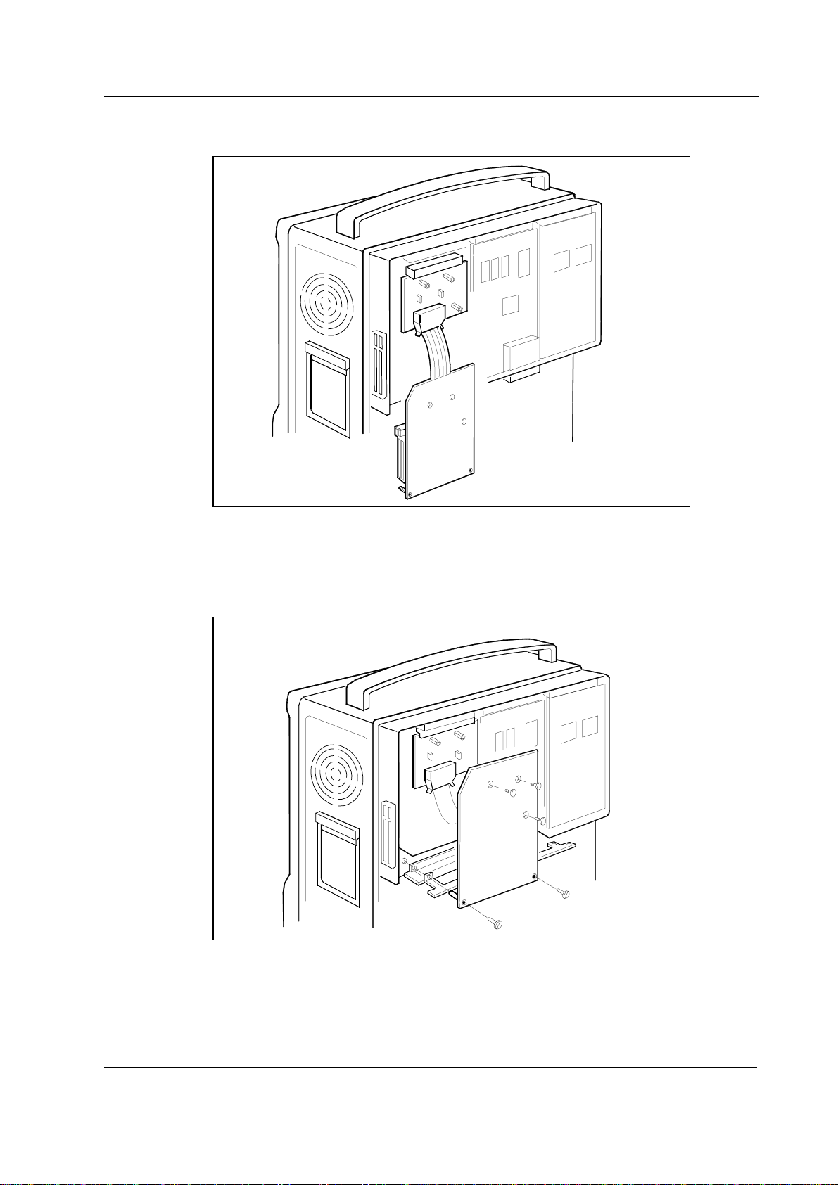
4. Unscrew the five screws holding the bottom plate in position and remove the plate.
5. Unscrew the screw holding the cover plate in position and remove the plate.
6. Remove the Memory Board, B-CMMEM, including the connection board and the memory
board, from the protective anti static packaging. Always hold the boards by the edges and
wear a wrist grounding strap.
2
CAUTION The Memory Board, B-CMMEM comprises sensitive integrated circuits that can be
damaged by an electrostatic discharge. Careful handling of the board is therefore
essential.
24
Document No. 896 623
Page 33
General Service Guide
7. Insert the connection board into the empty slot and firmly press the board in position.
8. Place the memory board, the bottom plate and the cover plate in position. First, secure the
memory board with the three screws in the sequence indicated. Then, secure the memory
board, the bottom plate and the cover plate with the two screws (M3x25). Finally, secure the
bottom plate (four screws).
2
1
3
9. Replace the back plate (six screws).
10. Reconnect the power cord.
25
Document No. 896 623
Page 34
Datex-Ohmeda AS/3 Compact Monitor, CS/3 Compact Monitor
3.5 AS/3 Memory Board, B-CMMEM Installation (w/ B-CMCPU4)
1. Make sure that the power is turned off on the Compact Monitor and unplug the Power Cord.
Press and hold the Service Reset button on the rear panel for at least five seconds until the
service reset indicator LED is switched off.
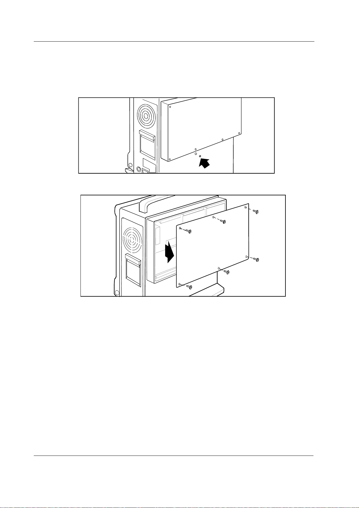
2. Unscrew the six screws holding the back plate in position and remove the plate.
WARNING The Compact Monitor is always energized by the internal battery. Do not touch
any exposured wiring or conductive surface with metallic object while the back
plate is off or electric failure may result.
CAUTION The Compact Monitor is always energized by the internal battery. A short circuit may
cause internal damage.
26
Document No. 896 623
Page 35

General Service Guide
3. Unscrew the two nuts holding the side plates in position and remove the plates. Put the
memory card collar in the place of the side plates.
2
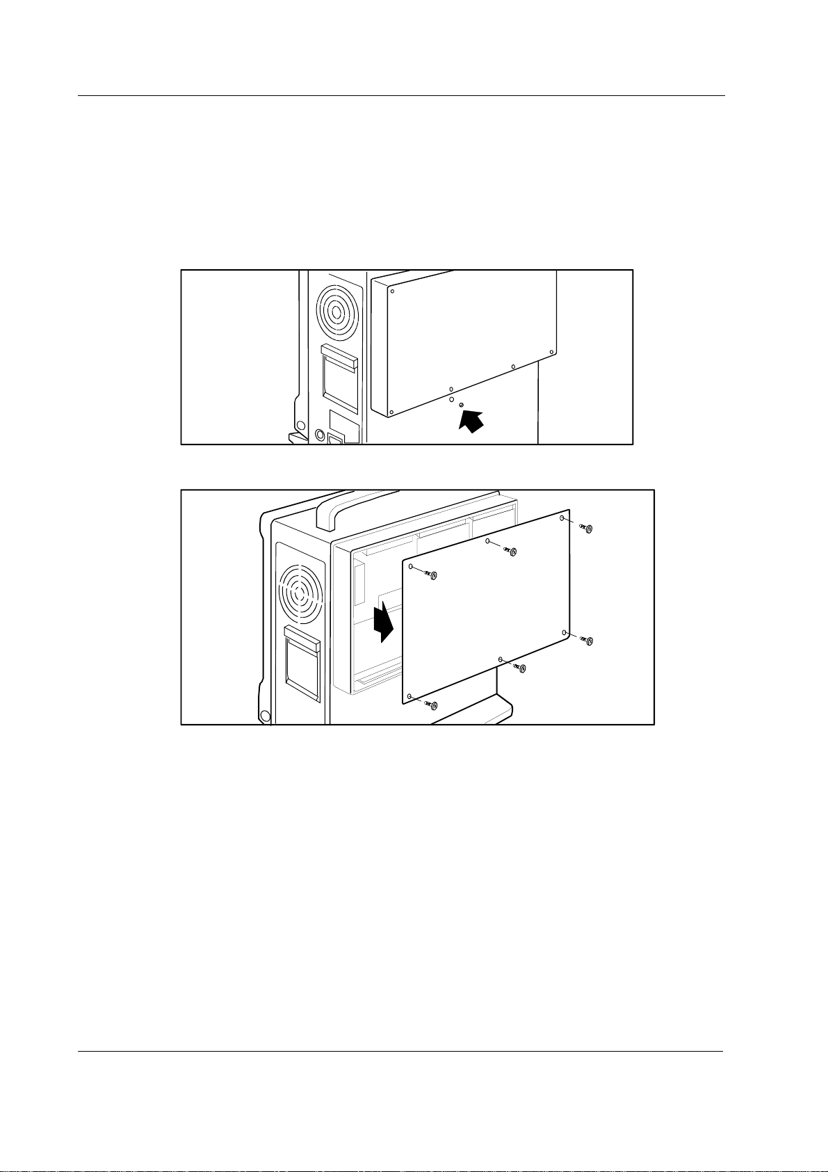
4. Unscrew the screws holding the bottom plate in position and remove the plate.
5. Remove the Memory Board, B-CMMEM, including the connection board and the memory
board, from the protective anti static packaging. Always hold the boards by the edges and
wear a wrist grounding strap.
CAUTION The Memory Board, B-CMMEM comprises sensitive integrated circuits that can be
damaged by an electrostatic discharge. Careful handling of the board is therefore
essential.
27
Document No. 896 623
Page 36

Datex-Ohmeda AS/3 Compact Monitor, CS/3 Compact Monitor
6. Insert the connection board into the empty slot and firmly press the board in position.
7. Place the memory board, the bottom plate and the cover plate in position. First, secure the
memory board with the three screws in the sequence indicated. Then, secure the memory
board, the bottom plate and the cover plate with the two screws (M3x25). Finally, secure the
bottom plate (four screws).
2
1
3
28
Document No. 896 623
8. Replace the back plate (six screws).
9. Reconnect the power cord.
Page 37

General Service Guide
3.6 Network Board, B-NET Installation (w/ B-CPU2/3)
Insert the Network Board, B-NET according to following procedure.
1. Make sure that the power is turned off on the Compact Monitor is and unplug the Power
Cord. Press and hold the Service Reset button on the rear panel for at least five seconds
until the service reset indicator LED is switched off.
2. Unscrew the six screws holding the back plate in position and remove the plate.
WARNING The Compact Monitor is always energized by the internal battery. Do not touch
any exposured wiring or conductive surface with metallic object while the back
plate is off or electric failure may result.
CAUTION The Compact Monitor is always energized by the internal battery. A short circuit may
cause internal damage.
29
Document No. 896 623
Page 38

Datex-Ohmeda AS/3 Compact Monitor, CS/3 Compact Monitor
3. Unscrew the five screws holding the bottom plate in position and remove the plate.
4. Unscrew the screw holding the cover plate in position and remove the plate.
5. Remove the Network Board, B-NET from the protective anti static packaging. Always hold
the board by the edges and wear a wrist grounding strap.
CAUTION The Network Board, B-NET comprises sensitive integrated circuits that can be
damaged by an electrostatic discharge. Careful handling of the board is therefore
essential.
30
Document No. 896 623
Page 39

General Service Guide
6. Loosen the two screws holding the EMC plate in position, remove the plate and tighten the
screws.
7. Insert the Network Board, B-NET into the empty slot and firmly press the board in position.
Secure the board with the screw removed from the cover plate earlier.
8. Replace the bottom plate and secure the plate with the five screws removed from the plate
earlier.
9. Replace the back plate and secure the plate with the six screws removed from the plate
earlier.
10. Reconnect the Power Cord.
Document No. 896 623
31
Page 40
Datex-Ohmeda AS/3 Compact Monitor, CS/3 Compact Monitor
3.7 Network Board, B-CMNET Installation (w/ B-CMCPU4)
Insert the Network Board, B-CMNET (B-CMNET differs from B-NET with mechanical changes)
according to following procedure.
1. Make sure that the power is turned off on the Compact Monitor is and unplug the Power
Cord. Press and hold the Service Reset button on the rear panel for at least five seconds
until the service reset indicator LED is switched off.
2. Unscrew the six screws holding the back plate in position and remove the plate.
WARNING The Compact Monitor is always energized by the internal battery. Do not touch
any exposured wiring or conductive surface with metallic object while the back
plate is off or electric failure may result.
CAUTION The Compact Monitor is always energized by the internal battery. A short circuit may
cause internal damage.
32
Document No. 896 623
Page 41

General Service Guide
3. Unscrew the screws holding the bottom plate in position and remove the plate.
4. Remove the Network Board, B-CMNET from the protective anti static packaging. Always hold
the board by the edges and wear a wrist grounding strap.
CAUTION The Network Board, B-CMNET comprises sensitive integrated circuits that can be
damaged by an electrostatic discharge. Careful handling of the board is therefore
essential.
5. Insert the Network Board, B-CMNET into the empty slot and firmly press the board in
position. Secure the board with the screw removed from the cover plate earlier.
6. Replace the back plate and secure the plate with the six screws removed from the plate
earlier.
7. Reconnect the Power Cord
33
Document No. 896 623
Page 42

Datex-Ohmeda AS/3 Compact Monitor, CS/3 Compact Monitor
3.8 AS/3 UPINET Board, B-UPINET Installation (w/ B-CPU2/3)
Insert the B-UPINET Board according to following procedure.
1. Make sure that the power is turned off on the Compact Monitor and unplug the Power Cord.
Press and hold the Service Reset button on the rear panel for at least five seconds until the
service reset indicator LED is switched off.
2. Unscrew the six screws holding the back plate in position and remove the plate.
WARNING The Compact Monitor is always energized by the internal battery. Do not touch
any exposured wiring or conductive surface with metallic object while the back
plate is off or electric failure may result.
CAUTION The Compact Monitor is always energized by the internal battery. A short circuit may
cause internal damage.
34
Document No. 896 623
Page 43

General Service Guide
3. Unscrew the two screws holding the software cartridge in position and remove the cartridge.
4. Unscrew the three screws holding the UPI Board in position and remove the board.
5. Remove the UPINET Board, B-UPINET from the protective antistatic packaging. Always hold
the board by the edges and wear a wrist grounding strap.
The UPINET Board, B-UPINET comprises sensitive integrated circuits that can be damaged by an
electrostatic discharge. Careful handling of the board is therefore essential.
35
Document No. 896 623
Page 44
Datex-Ohmeda AS/3 Compact Monitor, CS/3 Compact Monitor
6. Insert the UPINET Board, B-UPINET into the empty slot and firmly press the board in
position. Secure the board with the two screws removed from the UPI Board earlier.
7. Attach the EMC gasket to the EMC cases on the UPINET Board so that the adhesive part of
the gasket is against the cases. Place the right end of the gasket next to the back plate
screw hole in the lower right corner of the frame. Fit the gasket closely to the front plate.
8. Replace the Software Cartridge and secure the cartridge with the two screws removed from
the cartridge earlier.
9. Replace the back plate and secure the plate with the six screws removed from the plate
earlier.
10. Connect the B-NET connector cable to the network connector.
11. Reconnect the Power Cord.
NOTE: These instructions applies only for F-CM(REC) rev. 02 and rev. 03 and for F-CMC(REC) rev.
00 Compact Monitors. For earlier revisions also additional parts are required. Please contact your
authorized Datex-Ohmeda distributor.
36
Document No. 896 623
Page 45

General Service Guide
3.9 AS/3 UPINET Board, B-UPINET Installation (w/ B-CMCPU4)
Insert the B-UPINET Board according to following procedure.
1. Make sure that the power is turned off on the Compact Monitor and unplug the Power Cord.
Press and hold the Service Reset button on the rear panel for at least five seconds until the
service reset indicator LED is switched off.
2. Unscrew the six screws holding the back plate in position and remove the plate.
WARNING The Compact Monitor is always energized by the internal battery. Do not touch
any exposured wiring or conductive surface with metallic object while the back
plate is off or electric failure may result.
CAUTION The Compact Monitor is always energized by the internal battery. A short circuit may
cause internal damage.
37
Document No. 896 623
Page 46

Datex-Ohmeda AS/3 Compact Monitor, CS/3 Compact Monitor
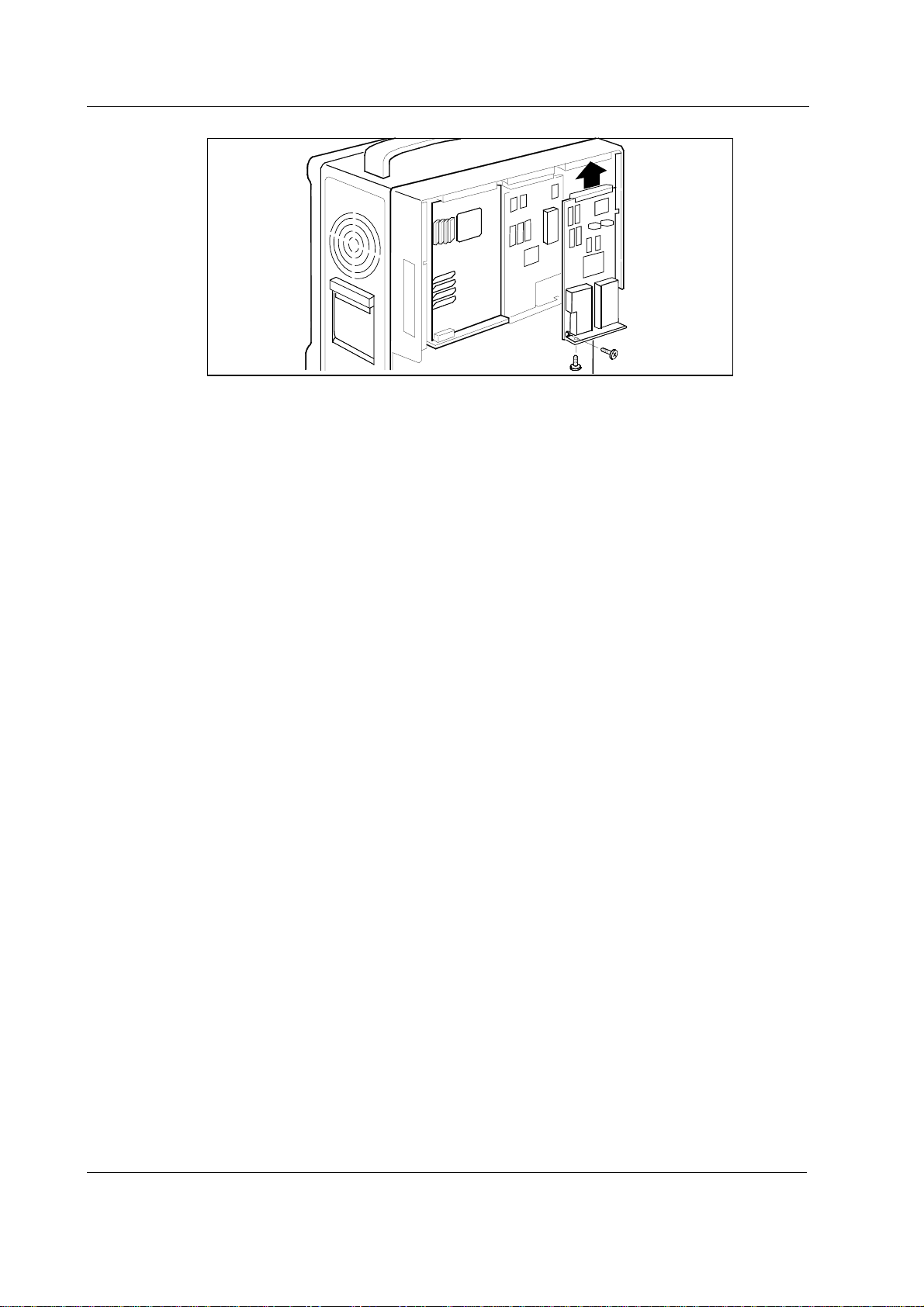
3. Unscrew the three screws holding the UPI Board in position and remove the board.
4. Remove the UPINET Board, B-UPINET from the protective antistatic packaging. Always hold
the board by the edges and wear a wrist grounding strap.
CAUTION The UPINET Board, B-UPINET comprises sensitive integrated circuits that can be
damaged by an electrostatic discharge. Careful handling of the board is therefore
essential.
5. Insert the UPINET Board, B-UPINET into the empty slot and firmly press the board in
position. Secure the board with the two screws removed from the UPI Board earlier.
6. Replace the back plate and secure the plate with the six screws removed from the plate
earlier.
7. Connect the B-NET connector cable to the network connector.
38
Document No. 896 623
8. Reconnect the Power Cord.
NOTE: These instructions applies only for F-CM(REC) rev. 04 and F-CMC(REC) rev. 01 Compact
Monitors. For earlier revisions also additional parts are required. Please contact your authorized
Datex-Ohmeda distributor.
Page 47

3.10 Compact Airway Modules, M-XXXX
Airway modules of M-family (M-C etc.) are installed as any plug-in modules.
Figure 10- Datex-Ohmeda Compact Airway Module
General Service Guide
3.10.1 Sample Gas Exhaust
When N2O or volatile anesthetics are used, pollution of the operation room by these gases should
be prevented. Connect the sample gas outlet of the module to the scavenging system or return it to
the patient circle.
Connect the sample gas outlet of the module to the scavenging system either
− through the ventilator reservoir.
− directly to the scavenging tube using a T-fitting.
Connect sample gas outlet only to open scavenging system where gas is removed in room
pressure.
CAUTION Strong scavenging suction may change the operating pressure of the module and
cause inaccurate readings or internal damage.
39
Document No. 896 623
Page 48

Datex-Ohmeda AS/3 Compact Monitor, CS/3 Compact Monitor
3.10.2 Scavenging Through Reservoir
SAMPLE GAS O UT
Figure 11 Scavenging through Ventilator Reservoir
• Connect an exhaust line to the sample gas outlet on the module’s front panel.
• Attach the other end of the line to the ventilator reservoir. Make sure that the reservoir tube
diameter is at least 2-3 times larger than the exhaust line.
3.10.3 Scavenging Through Direct Connection
Figure 12 Connection Directly to a Scavenging System
• Connect a T-fitting between the monitor and the exhaust line.
• Attach the other end of the line to the scavenging tube.
SAMPLE GAS OUT
40
Document No. 896 623
Page 49

3.10.4 Returning Gas to Patient Circuit
The sampling gas can also be returned to the patient circuit. If you use the Datex-OhmedaAS/3
Anesthesia Delivery Unit (ADU), you need an optional adapter connected to the patient breathing
tubes.
General Service Guide
Figure 13 Sample Gas Return to Patient Circuit in ADU
3.11 AS/3 Anesthesia Keyboard, K-ARK
To connect AS/3 Anesthesia Keyboard, K-ARK to the Compact Monitor:
1. Make sure that the power is turned off on the Compact Monitor.
2. Connect the Keyboard-LCD Display Cable to the K-ARK connector on the display and to the
connector on the rear of the keyboard. Secure the connection with the thumb screw and slip
the cable beneath the fasteners.
3.12 Remote Controller, K-REMCO
To connect a Remote Controller, K-REMCO to your Compact Monitor you need a Remote ControllerCompact Monitor Cable. For further information, please contact your authorized Datex-Ohmeda
distributor.
41
Document No. 896 623
Page 50

Datex-Ohmeda AS/3 Compact Monitor, CS/3 Compact Monitor
3.13 Bar Code Reader
3.13.1 Connection to the Compact Monitor
The bar code reader can be connected to the K-ARK connector on the monitor.
Figure 14 Bar Code Reader connected to the Compact Monitor
3.13.2 Different Configurations
The bar code reader comes from HP factory with factory default settings. These settings are slightly
modified at Datex-Ohmeda factory to match Datex-Ohmeda applications. The following table
shows the differences between the HP configuration and the Datex-Ohmeda configuration.
Option HP configuration Datex-Ohmeda configuration
Message components
Header [<<61>>] [hhh]
No-read [<<61>><<61>>] []
Keycodes
Key delay [1] ms [12] ms
The default settings can also be modified outside the factory by scanning special bar code labels
from the documentation that comes with the scanner. To do this the scanner should be connected
to the keyboard port of your PC.
42
Document No. 896 623
Page 51

General Service Guide
1. Start the configuration (Default Wedge Mode).
2. Begin with the header label (Header). Set the contents of the header to hhh.
3. End the header (End of Characters).
4. Clear the no-read message (No-Read Message is Empty).
5. Select the interkey delay (Interkey Delay). Set the interkey delay to 12 s.
The configuration of the bar code reader is shown by scanning the Show Configuration label.
CONFIGURATION DISPLAY
--- Version 14.3 -------------------------- (c) Hewlett-Packard 1986-1992
| CODE |READ |CHECK CHAR | LENGTH | CODE ID | OTHER CONFIG. SETTINGS |
|________|_____|verif_xmit_|min__max|xmit:[off]|--------------------------|
|Code 39 |[yes]|[no] | yes |[1] [32]| [a] |Extended: [no] |
|Int. 2/5|[yes]|[no] | yes |[4] [32]| [b] |Length: [variable] |
|Codabar |[yes]|[no] | yes |[1] [32]| [d] |Include start/stop: [yes] |
|Code 128|[yes]| yes | no |[1] [32]| [e] | |
|Code 11 |[yes]| [1] | yes |[2] [32]| [f] | |
|MSI Code|[yes]| yes | yes |[3] [32]| [g] | |
|Code 93 |[yes]| yes | no |[1] [32]| [h] | |
|UPC/EAN |[yes]| yes |[yes]| fixed | [c] |[+ none] |
| E:[0] |||| | |EAN:[yes] ID chars:[off]|
|----------- MESSAGE COMPONENTS ------------------------------------------|
| Ctrl character=^+letter ®nn¯ = Extended Key index |
|Header:[hhh] |
|Trailer:[^M] |
|No-Read:[] |
|--- KEYCODES --------- OPERATOR FEEDBACK ----------- GENERAL ------------|
|Key Delay:[10] ms |Ready Signal:[on] |[Wedge] (using keyboard) |
|[U.S. English] |Menu Scan Responses:[on] |No-Read Recognition:[off] |
|Code Set:[auto]->2|Good Read LED:[flashes] |Family:[auto]->PC/AT,PS/2 |
|ALT Sequence:[off]|LED Active:[high] |Ctrl Chars:[ASCII] |
-------------------------------------------------------------------------
43
Document No. 896 623
Page 52

Datex-Ohmeda AS/3 Compact Monitor, CS/3 Compact Monitor
3.14 Troubleshooting
If a problem occurs during the functional examination, check the components of the monitor
according to the following troubleshooting chart. If the problem persists, please refer to the part II.
TROUBLE TREATMENT
Nothing functions Unplug and replug Remote Controller Cable. Also confirm that the cable is intact.
Unplug and replug the Power Cord. Also confirm that the cable is intact.
Confirm that the fuses are intact.
A plug-in module does
not function
The airway module does
not function
Remove and replace the module.
Confirm that the desired parameters are configured to be displayed.
Confirm that “Occlusion” or “Calibrating Gas Sensor” messages are not displayed.
Confirm that a D-fend water trap and a sample tube are attached.
Confirm that the desired parameters are configured to be displayed.
Remove and replace the module.
44
Document No. 896 623
Page 53

4 INTERFACING
You can interface external devices to the AS/3 and CS/3 monitor via B-UPI or B-UPINET Board and
Interface Module (M-INT). For interfacing an intra-aortic balloon pump, ECG and pressure signals
are available from the M-PT module.
Via B-UPI or B-UPINET board you can interface:
• Datex-Ohmeda monitors
• AS/3 Anesthesia Delivery Unit
• printers
Via M-INT you can interface:
• Datex-Ohmeda monitors
• some monitors of other manufacturers
• some anesthesia machines
General Service Guide
45
Document No. 896 623
Page 54

Datex-Ohmeda AS/3 Compact Monitor, CS/3 Compact Monitor
4.1 Interfacing Monitors via UPI Board, B-UPI
The parameters transferred to the Compact Monitor are summarized in table 4-1.
4.1.1 Interconnection Datex-Ohmeda Monitors
Use the UPI-Monitor Cable to connect Compact Monitor to Datex-Ohmeda monitors.
1. Make sure that the power to both devices is turned off.
2. Connect the 9 pin D-shaped connector to the X3 connector and the 44 pin D-shaped
connector to the X2 connector on the UPI Board. Tighten the finger screws.
3. Connect the 25 pin D-shaped connector to the corresponding connector on the rear of the
other monitor. Tighten the finger screws.
Table 1 Transference of Parameters, Datex-Ohmeda Monitors
Device Waveforms (analog) Numerics Alarms
Cardiocap CO
Capnomac
CO
Capnomac II
2
2
Et&Fi Airway gases, Respiration
rate, SpO
, Pulse rate
2
Et&Fi Airway gases, Respiration
rate.
Capnomac Ultima CO2, Pleth Et&Fi Airway gases, Respiration
rate, Spirometry, Sp
, Pulse
O2
rate, Pleth amplitude
Normocap 200
Normocap 200
CO
2
Et&Fi Airway gases, Respiration
rate.
OXY
Oscar
Oscar II
Oscar OXY
Satlite
Satlite II
CO2, Pleth Et&Fi Airway gases, Respiration
rate, SpO
, Pulse rate, Pleth
2
amplitude
Pleth SpO2, Pulse rate, Pleth
amplitude
Satlite Plus
Satlite Trans None SpO2,, Pulse rate, Pleth
amplitude
None
None
CO
, O2, Anesthesia agent,
2
respiration rate, Apnea, occlusion,
, pulse rate.
SpO
2
None
None
None
None
46
Document No. 896 623
Page 55

General Service Guide
4.1.2 Setting the Interfacing Parameters
Set the serial output mode of Datex-Ohmeda monitors: Capnomac Ultima, Satlite Trans and
Normocap to numeric. This setting can be stored into permanent memory through the startup
menu. See the monitors’ manual for further information.
4.1.3 Setting the Interfacing Parameters for the Compact Monitor
1. Press the Monitor Setup key.
2. Select Install/Service password (16-4-34).
3. Select Interfacing and combine a required parameter with an external monitor. Two letters,
al, denote alarm integration. The selection will be automatically stored in permanent
memory.
4. Press the Normal Screen key.
4.2 Interfacing with Datex-Ohmeda Monitors via UPINET Board, B-UPINET
It is possible to interface Datex-Ohmeda monitors to the Compact Monitor via the UPINET Board, BUPINET. The parameters transferred to the Compact Monitor are summarized in table 4-1.
NOTE: Because the analog inputs are missing, waveforms are not transferred to the Compact
Monitor if the UPINET Board, B-UPINET is used.
Interconnection
Use the B-INT-External Device Cable to connect the Compact Monitor to Datex- Ohmeda monitors.
1. Make sure that the power is turned off on both devices.
2. Connect the 9 pin D-shaped connector to the corresponding connector on the UPINET
Board, B-UPINET.
3. Connect the remaining 25 pin D-shaped connector to the corresponding connector on the
rear of the other monitor. Tighten the finger screws.
Setting the Interfacing Parameters for Datex-Ohmeda Monitors
Set the interfacing parameters for the Datex-Ohmeda monitors according to previously described
procedure.
Setting the Interfacing Parameters for Compact Monitor
Set the interfacing parameters for the Compact Monitor according to previously described
procedure.
Document No. 896 623
47
Page 56

Datex-Ohmeda AS/3 Compact Monitor, CS/3 Compact Monitor
4.3 Interfacing Monitors via M-INT
It is possible to interface Datex-Ohmeda monitors, Critikon Dinamap 1846SX, Abbott Oximetrix 3,
Baxter Explorer and Vigilance, Nellcor N-100, N-200 and N-1000 to the Compact Monitor via the
Interface Module, M-INT. Interface Module, M-INT, has two serial and analog connectors (X7 and
X8). The parameters transferred are summarized in tables 4-1 and 4-2.
NOTE: Using the Interface Module , M-INT disables interfacing with Datex-Ohmeda monitors via the
UPI/UPINET Board.
WARNING Always make sure that the combination complies with the international safety
standard IEC 60601-1-1 for medical electrical systems and with the
requirements of local authorities.
Table 2 Transference of Parameters, Other Monitors
Device Waveforms Numerics Alarms
Critikon
Dinamap 1846SX
Abbott
Oximetrix 3
Baxter
Explorer
Baxter
Vigilance
Nellcor
N-100
N-200
N-1000
None NIBP None
None SvO2/SaO2, CO None
None C.O., SvO2, REF, Tblood None
None C.O., SvO2, C.C.O.,
Pleth (analog) SpO2, Pulse rate None
4.3.1 Connection to Datex-Ohmeda Monitors
Use the INT-External Device Cable.
1. Make sure that the power to both devices is turned off.
2. Connect the 9 pin D-shaped connector to one of the connectors on the Interface Module,
M-INT. Tighten the finger screws.
None
Tblood
48
Document No. 896 623
3. Connect the 25 pin D-shaped connector to the corresponding connector on the other
monitor. Tighten the finger screws.
Page 57

General Service Guide
4.3.2 Connection to Critikon Dinamap 1846SX, Abbott Oximetrix 3 and Baxter Explorer
Use the INT-External Device Cable.
1. Make sure that the power to both devices is turned off.
2. Connect the 9 pin D-shaped connector to one of the connectors on the Interface Module,
M-INT. Tighten the finger screws.
3. Connect the remaining 25 pin D-shaped connector to the connector on the other monitor.
Tighten the finger screws.
4.3.3 Connection to Baxter Vigilance
Use the INT-Baxter Vigilance Cable.
1. Make sure that the power to both devices is turned off.
2. Connect one of the connectors to the corresponding connector on the Interface Module, M-
INT. Tighten the finger screws.
3. Connect the other 9 pin D-shaped connector to the on the other monitor. Tighten the finger
screws.
4.3.4 Connection to Nellcor N-100 and N-1000
Use the Monitor-Nellcor Cable.
1. Make sure that the power to both devices is turned off.
2. Connect the 9 pin D-shaped connector to on of the connectors on the Interface Module, M-
INT. Tighten the finger screws.
3. Connect the mono connectors to the corresponding connectors on the other monitor.
4.3.5 Connection to Nellcor N-200
Use the Monitor-Nellcor Cable.
1. Make sure that the power to both devices is turned off.
2. Connect one of the connectors to the corresponding connector on the Interface Module, M-
INT. Tighten the finger screws.
3. Connect the other connector to the corresponding connector on the other monitor. Tighten
the finger screws.
4. Connect the mono connectors to the corresponding connectors on the other monitor.
4.4 Interfacing Datex-OhmedaAS/3 Anesthesia Delivery Unit
It is possible to interface Datex-Ohmeda Anesthesia Delivery Unit to the Compact Monitor via the
UPI Board.
For further information, please contact your authorized Datex-Ohmeda distributor.
49
Document No. 896 623
Page 58

Datex-Ohmeda AS/3 Compact Monitor, CS/3 Compact Monitor
4.5 Interfacing Dräger Cicero and Cato
It is possible to interface Dräger Cicero and Cato to the Compact Monitor via the Interface Module,
M-INT.
For further information, please contact your authorized Datex-Ohmeda distributor.
WARNING Always make sure that the combination complies with the international safety
standard IEC 60601-1-1 for medical electrical systems and with the
requirements of local authorities.
4.6 Interfacing a printer
It is possible to interface a laser printer (either serial or parallel) to the Compact Monitor via the UPI
Board. Only serial printer can also be interfaced via the UPINET board. The printer must be PCL5
compatible.
WARNING Always make sure that the combination complies with the international safety
standard IEC 60601-1-1 for medical electrical systems and with the
requirements of local authorities.
WARNING Connecting the power supply cord of the printer to the wall socket may cause
the printer leakage current to exceed the limit specified for medical equipment.
Always connect the printer to an appropriate separating transformer.
4.7 Interfacing a computer
It is possible to interface a computer to Compact Monitor. For further information, please contact
your authorized Datex-Ohmeda distributor.
WARNING Always make sure that the combination complies with the international safety
standard IEC 60601-1-1 for medical electrical systems and with the
requirements of local authorities.
WARNING Connecting the power supply cord of the computer to the wall socket may cause
the computer leakage current to exceed the limit specified for medical
equipment. Always connect the computer to an appropriate separating
transformer.
50
Document No. 896 623
Page 59

General Service Guide
4.8 UPI Board Output Signals
The analog and digital connector X2 on the UPI Board, can be used to interface other devices to the
Compact Monitor. Pin assignments are listed in table 4-3.
WARNING Always make sure that the combination complies with the international safety
standard IEC 60601-1-1 for medical electrical systems and with the
requirements of local authorities.
4.8.1 Digital Outputs
The digital output signals are as follows:
Defibrillation Sync
The defibrillation sync signal is generated by the ECG. When activated, the signal is set to a high
state and then set back to a low state after 10 ms. The signal is regenerated only after returning to
the low state. The high state ranges from 2.8 to 5 V while the low state ranges from 0 to 0.8 V. The
delay from the R wave peak to the start of the signal is maximally 35 ms.
Nurse Call
The nurse call signal is generated by red, yellow and white alarms. When activated, the signal is set
to a high state and remains at a high state until the alarm situation is over or the Silence Alarm
key is pressed. The high state ranges from 2.8 to 5 V while the low state ranges from 0 to 0.8 V.
Pacemaker Sync
The pacemaker sync signal is generated by pacemaker pulses on the ECG. When activated, the
signal is set to a high state and then set back to a low state such that the signal pulse width is
between 0.5 to 2.5 ms. The high state ranges from 2.8 to 5 V while the low state ranges from 0 to
0.8 V.
Table 3 Analog and Digital Connector Pin Assignments
Pin Signal
1
2
3
4
5
6
7
8
9
10
11
12
13
14
15
16
GND
Digital input 3
Digital output 0, Defibrillation sign
Digital input 2
Digital output 1, Nurse call
Digital output 3
Ground
Digital output 2, Pacemaker sign
Analog input, Ch3
Analog output Ch 5
Not connected
Not connected
Analog input, Ch 0
Analog output, Ch 1
+5 V
Analog output, Ch 4
51
Document No. 896 623
Page 60

Datex-Ohmeda AS/3 Compact Monitor, CS/3 Compact Monitor
Pin Signal
17
18
19
20
21
22
23
24
25
26
27
28
29
30
31
32
33
34
35
36
37
38
39
40
41
42
43
44
Analog output, Ch 3
Analog input, Ch 1
Analog output, Ch 2
Analog output, Ch 0
Digital input 4
Analog input Ch 2
Digital input 5
Analog output, Ch 6
Analog output Ch 7
Not connected
Not connected
Not connected
Data 0, output
Data 1, output
Data 2, output
Data 3, output
Data 4, output
Data 5, output
Data 6, output
Data 7, output
Not connected
Fast analog ECG
Not connected
Busy, input
Paper End, input
Error, input
Strobe, output
GND
4.8.2 Analog Outputs
The analog output signals are:
Each signal is scaled in linear way between -5 ... +5 volts. The resolution consists of 4096 different
voltage levels. All signal levels are updated once in 10 ms.
OFF: Default state. No signal is present at analog output pin.
HR according to selected source (display value): The original scale 0...300 beats are scaled
between 0 and 3 volts.
ECGl, ECG2, ECG3: The original scale -5000 microvolts...+5000 microvolts is scaled between -5
and +5 volts.
P1 lre, P2 lre, P3 lre, P4 lre, P5 lre, P6 lre (Invasive pressure real-time values, low resolution): The
original scale -20 mmHg...+320 mmHg is scaled between -0.2 and +3.2 volts.
P1 hre, P2 hre, P3 hre, P4 hre, P5 hre, P6 hre (Invasive pressure real-time values, high resolution):
The original scale -20 mmHg...+50 mmHg is scaled between -2 and +5 volts.
Pleth: The original scale -100%...100% is scaled between -5 and +5 volts.
52
Document No. 896 623
Page 61

General Service Guide
SpO2>40, SpO2>60, SpO2>80 (beat-to-beat, display value, 10 s average): The original scale 40100% (SpO
>40), 60-100% (SpO2>60) or 80-100% (SpO2>80) is scaled between -5 and +5
2
volts.
: The original scale 0%...10% is scaled between 0 and +5 volts. Values greater than 10% are
CO
2
set to 10%. (Airway gas special indications are applied, see also chapter Special Indications).
AA (Anesthesia Agent): The original scale 0%...10% is scaled between 0 and +5 volts. Values
greater than 10% are set to 10%. (Airway gas special indications are applied, see also chapter
Special Indications).
: The original scale 0%...100% is scaled between 0 and +5 volts. (Airway gas special indications
O
2
are applied, see also chapter Special Indications).
O: The original scale 0%...100% is scaled between 0 and +5 volts. (Airway gas special
N
2
indications are applied, see also chapter Special Indications).
Paw (Airway Pressure): The original scale -20 cmH2O...+80 cmH2O is scaled between -5 and +5
volts. (Airway gas sensor failure is applied, see also chapter Special Indications).
Flow: The original scale -100 l/min...+100 l/min is scaled between -5 and +5 volts. (Airway gas
sensor failure is applied, see also chapter Special Indications).
Volume: The original scale -2.5 litters...+2.5 litters is scaled between -5 and +5 volts. (Airway gas
sensor failure is applied, see also chapter Special Indications).
Resp: The original scale -5000 mohms is scaled between -5 and +5 volts.
RR: RR display 0 to 150 breaths per minute are scaled between 0 and +1.5 volts.
T1, T2, T3, T4 (Temperature): The original scale 0 degrees...50 degrees Celcius is scaled between 0
and +5 volts.
TEST SIGNALS -5 V, 0 V, +5 V: Steady signals with one of the listed values.
TEST 1: Test signal of a triangle shape with base width of 1 second, min value of 0 volt and max
value of 5 volts.
TEST 2: Test signal of a triangle shape with base width of 4 seconds, min value of -5 volts and max
value of +5 volts.
4.8.3 Setting the Analog Output Signals
Set the analog output signals according to the following procedure.
1. Press the Monitor Setup key .
2. Select Install/Service and enter the password (16-4-34) to get into the corresponding
menu.
3. Select Analog Outputs to get into the corresponding menu and combine a required channel
with an output signal.
4. Press the Normal Screen key.
53
Document No. 896 623
Page 62
Datex-Ohmeda AS/3 Compact Monitor, CS/3 Compact Monitor
4.9 Pressure Temp Module, M-PT Output Signals
The signal output connector on the Pressure Temp Module, M-PT can be used to interface some
models of IABPs to the Anesthesia Monitor/Critical Care Monitor. The pin assignments are
illustrated in table 4-12. Please contact your local distributor for more information.
WARNING Always make sure that the combination complies with the international safety
standard IEC 60601-1-1 for medical electrical systems and with the
requirements of local authorities.
Table 4 Signal Output Connector Pin Assignments
Pin Signal
1
2
3
4
4.9.1 Analog Outputs
The analog output signals are:
ECG (ECG1)
The ECG signal is 1 V/1 mV with a delay of approximately 10 ms. The signal requires an input
impedance of 100 kΩ.
NOTE: The ECG signal is based on the ECG measurement of the ESTPR Module, M-ESTPR (all
variations), and of the NESTPR Module, M-NESTPR (all variations). ECG signal from the module is
channel 1 (ECG1). The channels 2 and 3 (ECG2, ECG3) are not transmitted. Make sure that the
signal in channel 1 (ECG1) is good enough (extensive QRS for IABP synchronization). For further
information, please contact your authorized Datex-Ohmeda distributor.
Invasive Pressure (P3)
The Invasive pressure output signal is 1 V/100 mmHg originally ranging from 0 to 300 mmHg and
with a delay of approximately 25 ms. The signal requires an input impedance of 100 kΩ.
ECG out, ECG1
Pressure out, P3
ECG out, ECG1
Ground
54
Document No. 896 623
Page 63

5 FUNCTIONAL CHECK
This instruction includes procedures for a functional check for Datex-Ohmeda AS/3 Compact
Monitor and CS/3 Compact Monitor running with the S-__99(A) software. However, most of the
procedures also apply to monitors with older monitor software.
The functional check is recommended to be performed after monitor installation.
Perform the procedures in the ascending order and skip the items that do not correspond to the
particular monitor.
The instructions include a check form (Appendix A) to be filled in when performing the
corresponding procedures.
General Service Guide
The symbol
check form.
? in the instructions means that the performed procedure should be signed in the
5.1 Recommended tools
Tool Order No. For product(s)
Sampling line 2.0 m 73318 Compact Airway Module, M-COVX/-
SpO2 finger probe SAS-F4 Hemodynamic modules w/ (S)
Adult NIBP cuff 572435 Hemodynamic modules w/ (NIBP)
Adult NIBP hose 877235 Hemodynamic modules w/ (NIBP)
Nellcor SpO2 probe - M-NSAT
Earphones - M-EEG
TonometricsTM catheter M-TONO
MemCard - Menu - M-MEM
MemCard - Data - M-MEM
Screwdriver - All
CAiOVX
5.2 Visual inspection/preparation
• Make sure that the monitor is turned off.
• Disconnect the mains power cord and press the service reset- switch until the LED next to it
turns off.
• If the monitor is connected to the Datex-Ohmeda network, disconnect the Mon-Net cable
from the monitor’s Network extension cable. If the Memory Board, B-CMNET or the Memory
Module, M-MEM, is connected, remove any memory cards.
55
Document No. 896 623
Page 64

Datex-Ohmeda AS/3 CM and CS/3 CMC
General
1. Check the external parts:
− All the four rubber pads under the monitor are in place.
− All the stickers are intact.
− The LCD screen is intact.
− The ComWheel cover is intact and attached properly.
− The ON/STBY -switch and it’s protector are intact and attached properly.
− All connectors are clean and intact.
− The thumb screws for cables on PC boards are intact.
− The software card slot is covered with a lid (B-CMCPU4).
− The service reset- switch is intact.
− The handle is attached properly.
− The outer cover is intact
?
2. Check that modules go in smoothly and lock up properly in all module slots.
?
Anesthesia Keyboard, K-ARK
3. Check external parts:
− the anesthesia keyboard plastic frame is intact
− the front panel stickers are intact
− the ComWheel cover is intact and is attached properly
− all four rubber pads are in place on the bottom cover
Check the anesthesia keyboard interface cable:
− the cable is intact
− the cable is connected and locked properly
?
Remote Controller, K-REMCO
4. Check external parts:
− the remote controller plastic frame is intact
− the keypad is intact
− the ComWheel cover is intact and attached properly
− the screws at the bottom are tightened properly
56
Document No. 896 623
Check the remote controller interface cable:
− the cable is intact
− the cable is connected and locked properly
?
Page 65

Compact Airway Module, M-CXXXXX
5. Disconnect the module and check external parts:
− the front cover and the front panel stickers are intact
− all connectors are intact and are attached properly
− the D-fend latch moves properly
− the module box is intact
− the module latch is intact and moves properly
Plug the module back into the monitor.
?
Tonometry Module
6. Disconnect the module and check the external parts:
− the front cover and the front panel sticker are intact
− connectors are intact and are attached properly
− the module box, latch and spring locking pin are intact
General Service Guide
Plug the module back into the monitor.
?
Other plug-in modules and N-EEG
7. Unplug the modules one by one and check external parts:
− the front cover and the front panel sticker are intact
− all connectors are intact
− all mechanical parts are functioning properly
− the module box and the latch are intact
− the module bus connector is clean and intact
Plug the modules back into the monitor.
?
8. Check external parts of the EEG Headbox, N-EEG and connect the EEG Headbox to the EEG
Module.
?
57
Document No. 896 623
Page 66

Datex-Ohmeda AS/3 CM and CS/3 CMC
5.3 Functional Inspection
Start up
9. Connect the mains power cord to the Frame.
Check that the stand-by LED is lit .
?
10. Check that the fans start running.
?
11. Turn the monitor on. Check that the monitor starts up properly, i.e.
− the alarm LED’s turn on and off
− the start-up sound is heard from the loudspeaker
− the normal monitoring screen appears
− no error messages appear onto the screen
− If the monitor contains a recorder, two lines of start-up information should be
recorded.
Monitor setup
?
12. Configure the monitor screen so that all required parameter information is displayed:
Monitor Setup - Screen 1 Setup - Waveform Fields
- Digit Fields
Check that all of the connected modules are recognized, i.e. the required parameter
information is displayed on the screen.
NOTE: The InvBP waveform is not displayed if the InvBP cable is not connected
If some parameter information is missing, check that the interfacing settings are correct:
Monitor Setup - Install/Service (Password 16-4-34)
Installation - Interfacing.
?
13. Preset the measurement settings for the connected parameters, for examples:
Monitor Setup - Screen 1 Setup - Digit Fields -Lower Field 4 - PgCO
2
Others - EEG - EEG Setup - Numeric 1 - MF
- Numeric 2 - Ampl.
- Montage - EEG Channels - 4
- Montage type - Bip
- EP - Cycle - Cont.
- EP Size - 1
- AEP Setup - AEP Channels - 2
58
Document No. 896 623
Page 67

- Responses -100
- Stim. Frequency - 1.1Hz
- Stim. Intensity - 90 dB
- Sweep length - 100 ms
Record/ Print - Record Waveforms - Waveform 1 - ECG1
- Waveform 2 - P1
- Waveform 3 - P2
ECG - ECG Setup - HR Source - AUTO
Invasive Pressures - P1 ‘ART’ Setup - Label - ART
- P2 ‘CVP’ Setup - Label - CVP
- P3 Setup - Label - PA
- P4 Setup - Label - P4
- P5 Setup - Label - P5
- P6 Setup - Label - P6
General Service Guide
S-ANE99(A)
L-ARK99(A)
S-ICU99(A)
Pulse Oximetry - Pleth Scale - AUTO
Airway Gas - Spirometry Loops - Scaling - Indep.
- Paw Scale - 20
- Flow Scale - 15
Others - C.O. - C.O. Setup - Scale - 1.0 °C
- Injectate Volume - 10 ml
- Measurement Type - Set
- SvO2 - Update HB - 115 g/l
Others - SPO2 Setup - Pleth Scale - AUTO
Ventil. - Spirometry Setup - Scaling - Indep.
- Paw Scale - 20
- Flow Scale - 15
Wedge C.O: SVO2 - C.O. View - C.O. Setup - Scale - 1.0 °C
- Injectate Volume - 10 ml
- Measurement Type - Set
- SvO2 - Update HB - 115 g/l
Others - NMT - Stimulus Mode - TOF
- Cycle Time - 10 sec
- NMT Setup - Current - s(70mA)
µµµµ
- Pulse Width - 200
- Stim. Beep Volume - 2
- - Resp Setup - Size - 1.0
- Resp Rate Source - AUTO
- Measurement - ON
- Detection Limit - AUTO
s
?
59
Document No. 896 623
Page 68

Datex-Ohmeda AS/3 CM and CS/3 CMC
LCD display
14. Check that the picture on the LCD display screen is clear and stable.
Press Monitor Setup key and select:
Install/Service (password 16-4-34)- Service (password 26-23-8) - Display
Select Colors and check that all colors are clear.
Press the ComWheel and return to the Install/Service menu by selecting Previous Menu
twice.
?
15. Monitors with software S-_97 and F-CM(REC) Rev 03 or F-CMC(REC) Rev 00 or newer:
Check the LCD display screen setup:
Installation - Display Setup - LCD Colors.
Check that the menu and digit field background colors change between the settings 8 and
16. Return the original setting.
?
Command Board / Anesthesia Keyboard
16. Press the Help key. Check that the key opens the corresponding menu on the screen.
Turn the ComWheel in both directions and check that the cursor in the menu moves
correspondingly.
Highlight Normal Screen, press the ComWheel and check that the menu disappears from
the screen.
?
17. Check the Command board membrane keys, and the corresponding keys on the Anesthesia
keyboard, if connected.
Press the keys one by one. Check that each key generates a sound from the loudspeaker
and the corresponding text in Service Data changes its color.
?
Remote Controller
60
Document No. 896 623
18. Press the Menu key. Check that the key opens the corresponding menu on the screen.
Turn the ComWheel in both directions and check that the cursor in the menu moves
correspondingly.
Highlight Normal Screen, press the ComWheel and check that the menu disappears from
the screen.
?
Page 69

Compact Monitor Frame
19. Check that the clock on the screen shows correct time.
If necessary adjust the time:
Monitor Setup - Time and Date
NOTE: You cannot change the monitor’s time after a case has started. This prevents losing the
trend data.
NOTE: If the clock time shows 0:00 continuously (at successive start-ups), the
SRAM/TIMEKEEPER chip on the CPU Board, or its battery, needs to be replaced.
The Factory Reset should be performed if the chip or battery is replaced.
?
20. Check the loudspeaker by setting the alarm sound:
Alarms Setup - Alarm Volume
Test the whole volume scale from 1 to 10 by turning the ComWheel and check that the alarm
volume changes correspondingly. The alarm sound should be clear and audible at all
settings.
General Service Guide
?
21. Preset the battery settings:
Monitor Setup - Battery Setup - Charging Speed - Normal
- LCD Brightness- Bright
- Install/Service (password 16-4-34) -
Service (password 26-23-8) - Frame - Power Supply - Battery
Check that the following values are within the given limits:
“Temperature (C)”
“Voltage (V)”
Check that the ‘Timeouts’, ‘Bad checksums’ and ‘Bad c-s by mod’ values are not increasing
20-40
20-32
faster than by 50 per second. Check also that the Battery Supervisor Board (BSB) memories
have passed the internal memory test, i.e. the “RAM”, “ROM” and “EEPROM” all state OK.
?
22. Disconnect the power cord (without turning the monitor standby) and check, that the battery
indicator appears onto the upper right hand corner of the screen:
+
-
Reconnect the power cord and check that during charging, the charging symbol is displayed:
+
-
Charge
?
61
Document No. 896 623
Page 70

Datex-Ohmeda AS/3 CM and CS/3 CMC
Compact Airway Module
23. Check that the fan is running.
?
24. Select the pressure and the flow waveform on the monitor screen:
Monitor Setup - Screen 1 Setup - Waveform Fields - Field 5 - Paw
- Field 6 - Flow
S-ANE99(A)
L-ARK99(A)
S-ICU99(A)
Airway Gas - Agent/N2O Setup - Agent Measurement - ON
- Spirometry Loops - Scaling - Indep.
- Paw Scale - 20
- Flow Scale - 15
Ventil. - Spirometry Setup - Scaling - Indep.
- Paw Scale - 20
- Flow Scale - 15
Wait until the message ‘Calibrating gas sensor’ disappears from the screen, then enter the
Airway Module service menu:
Monitor Setup - Install/Service (password 16-4-34) -
Service (password 26-23-8) - Parameters - Gas Unit - General
Check that the module configuration displayed corresponds with the Compact Airway Module
type being used.
?
25. Check that the ‘Timeouts’, ‘Bad checksums’ and ‘Bad c-s by mod’ values are not increasing
faster than by 50 per second.
A value increasing faster than this indicates a failure in Module Bus communication.
62
Document No. 896 623
?
26. Enter the ... Gas Unit - Gases service menu.
Check that the ‘Ambient’ value displayed corresponds with the current ambient pressure
(±20 mmHg)
?
27. Check that the flow measurement offset, i.e. the sample ‘Zero’ value displayed is within
±10 ml/min.
?
Page 71

General Service Guide
28. Check that the ‘Amb-Work’ value in the service menu is within the following range:
Amb-Work (mmHg) 70-115 40-75
?
29. Block the tip of the sampling line with your finger and check that the message ‘Sample line
blocked’ appears on the monitor screen within 30 seconds.
?
30. Detach the D-fend and check that the messages ‘Check D-fend’ appears on the monitor
screen within 30 seconds.
?
31. Breath shortly into the sampling line.
Check that the CO
?
Tonometry Module, M-TONO
M-COVX/CAiOVX
waveform moves up the screen.
2
Others
32. Enter the tonometry module service menu:
Monitor Setup - Install/Service (password 16-4-34) -
Service (password 26-23-8)...Parameters - More - TONO
Check that the ‘Timeouts’, ‘Bad checksums’ and ‘Bad c-s by mod’ values are not increasing
faster than by 50 per second. Check that the memories of the module have passed the
internal memory test, i.e. ‘RAM’, ‘ROM’ and ‘EEPROM’ all state OK. Check that the general
error status, module pneumatics error status, module hardware error status and testbit
status are zero.
?
33. Connect the catheter to the tonometry module. Start tonometric measurement by pressing
the Start-Stop key on the module.
If measurement is turned on PgCO2 time bat replaces the Meas Off text. Check that the
catheter fills up. Stop the measurement by pressing the
Off text appears on the digit field.
?
Start-Stop key. Check that Meas.
63
Document No. 896 623
Page 72

Datex-Ohmeda AS/3 CM and CS/3 CMC
Hemodynamic Modules
ECG measurement
34. Enter the ESTP : ECG service menu:
Monitor Setup - Install/Service (password 16-4-34) -
Service (password 26-23-8) - Parameters - ESTP : ECG
Check that the ‘Timeouts’, ‘Bad checksums’ and ‘Bad c-s by mod’ values are not increasing
faster than by 50 per second. Check that the ECG/RESP board memories have passed the
internal memory test, i.e. ‘RAM’, ‘ROM’ and ‘EEPROM’ all state OK.
?
35. Check the module membrane key ECG LEAD (not available in NE12STPR/NESTPR type
modules).
Press the key at least for two seconds. Check that the selected ECG lead is changing on the
screen and the state for ‘Button’ in the service menu.
?
36. Check that the module mains power frequency ‘Power Freq’ value has been set according to
the supply frequency. If necessary change the setting by selecting Power Freq.
?
For modules w/ respiration measurement
37. Check on the ESTP : ECG service menu that the ‘Resp Available’ and ‘RESP Measurement’
show ON
?
For modules w/ temperature measurement
38. Enter the ESTP : STP service menu:
MODULES - ESTP : STP
Check that the ‘Timeouts’, ‘Bad checksums’ and ‘Bad c-s by mod’ values are not increasing
faster than by 50 per second. Check that the STP board memories have passed the internal
memory test, i.e. ‘RAM’, ‘ROM’ and ‘EEPROM’ all show OK.
64
Document No. 896 623
?
39. Check that the protection for temperature calibration is on, and the module configuration is
set correctly.
The ‘Protect key’ text in the menu should state OFF and the ‘Protect mode’ text should state
ON.
Page 73

The configuration in use is shown next to the ‘Configuration’ text and it may be either STP,
ST or TP.
If necessary change the protection mode, or the module configuration on the Calibrations menu.
?
For modules w/ invasive blood pressure measurement
40. Check the module membrane keys that are related to the InvBP or temperature
measurement:
Press each of the keys for at least one second. Check on the service menu that the key being
pressed is identified, i.e. one of the texts for ‘Buttons’ changes from OFF to ON .
?
For modules w/ SpO2 measurement
General Service Guide
41. Check that the message ‘No probe’ is shown when an SpO
Connect a SpO
finger probe to the module. Check that the message ‘Probe off’ is shown
2
when the probe is not connected to a finger.
?
42. Attach the SpO
probe to your finger. Check that a reading of 95-99 and a SpO2 waveform
2
appear. Check that the HR value is calculated from SpO
are not connected.
?
For modules w/ non invasive blood pressure measurement
43. Enter the NIBP module service menu:
Monitor Setup - Install/Service (password 16-4-34) -
Service (password 26-23-8) - Parameters - NIBP
Check that the ‘Timeouts’, ‘Bad checksums’ and ‘Bad c-s by mod’ values are not increasing
faster than by 50 per second. Check that the NIBP board memories have passed the
internal memory test, i.e. ‘RAM’, ‘ROM’ and ‘EEPROM’ all show OK.
sensor is not connected.
2
when ECG and InvBP (P1) cables
2
?
44. Check the module membrane keys.
Press each of the two NIBP related membrane keys twice. Check that the NIBP pump turns on
for a short time in both cases.
?
65
Document No. 896 623
Page 74

Datex-Ohmeda AS/3 CM and CS/3 CMC
45. Attach an adult NIBP cuff onto your arm and perform one NIBP measurement. Check the
module identifies the cuff, i.e. the text ‘Adult’ appears in the NIBP digit field for a short time.
Check that the module gives a reasonable measured result.
?
EEG Module, M-EEG and EEG Headbox, N-EEG
46. Enter the EEG module service menu:
Monitor Setup - Install/Service (password 16-4-34) -
Service (password 26-23-8) - Parameters - More… - EEG & EP
Select Module.
Check that the ‘Mod Mon Timeouts’, ‘Mod Mon Bad checksums’ and ‘Mon Mod Bad
checksums’ values in the module view are not increasing faster than by 50 per second.
Check that the memories of the module have passed the internal memory test, i.e. ‘RAM’,
‘ROM’ and ‘EEPROM’ all state OK.
?
47. Plug in the earphones to the headbox. Be careful with load stimulation from the earphones
when starting AEP stimulation. Start AEP stimulation by pressing the EP Start/Stop key on
the module. Check that the clicking sound comes from the earphones in 1.1 Hz frequency.
Stop the stimulation by pressing again the
the clicking stopped.
?
Pressure/Pressure Temp Modules, M-P/-PT
48. Enter the P/PT module service menu:
Monitor Setup - Install/Service (password 16-4-34) -
Service (password 26-23-8) - Parameters - P/PT
Check that the ‘Timeouts’, ‘Bad checksums’ and ‘Bad c-s by mod’ values are not increasing
faster than by 50 per second. Check that the PT board memories have passed the internal
memory test, i.e. ‘RAM’, ‘ROM’ and ‘EEPROM’ all show OK.
?
EP Start/Stop key on the module. Check that
Invasive blood pressure measurement
49. Check the module membrane
Press the key for at least one second. Check that the key being pressed is identified, i.e. the
text in the service menu for ‘Button’ changes from OFF to ON.
?
66
Document No. 896 623
Zero P3 key.
Page 75

50. Check that the module configuration is set correctly. The configuration in use is displayed
next to the ‘Configuration’ text in the service menu and it can be either BP or PT. If
necessary, change the configuration in the Calibrations -menu.
?
For modules w/ temperature measurement
51. Check that the protection for temperature calibration is on.
The ‘Protect key’ text in the menu should state OFF and the ‘Protect mode’ text should state
ON.
If necessary change the protection mode in the Calibrations -menu.
?
Dual pressure Module, M-PP
52. Enter the PP module service menu:
General Service Guide
Monitor Setup - Install/Service (password 16-4-34) -
Service (password 26-23-8) - Parameters - PP
Check that the ‘Timeouts’, ‘Bad checksums’ and ‘Bad c-s by mod’ values are not increasing
faster than by 50 per second. Check that the Dual Pressure module, M-PP, memories have
passed the internal memory test, i.e. ‘RAM’, ‘ROM’ and ‘EEPROM’ all show OK.
?
53. Check the module Zero P5 and Zero P6 membrane keys.
Press each of the keys for at least for second. Check that the key being pressed is
identified, i.e. one of the texts in the service menu for ‘Button’ changes from OFF to ON.
?
Cardiac Output Modules, M-COP/-COPSv
54. Enter the COP module service menu:
Monitor Setup - Install/Service (password 16-4-34) -
Service (password 26-23-8) - Parameters - COP
Check that the ‘Timeouts’, ‘Bad checksums’ and ‘Bad c-s by mod’ values are not increasing
faster than by 50 per second. Check that the module’s memories have passed the internal
memory test, i.e. ‘RAM’, ‘ROM’ and ‘EEPROM’ all show OK.
?
67
Document No. 896 623
Page 76

Datex-Ohmeda AS/3 CM and CS/3 CMC
Invasive blood pressure measurement
55. Check the module membrane
Press the key for at least one second. Check that the key being pressed is identified, i.e. the
information on the service menu under ‘Button’ - ‘P4’ changes from OFF to ON.
?
SvO2 measurement
56. Check that the SvO
service menu all show NO OM.
?
Cardiac Output measurement
57. Check the
Enter the COP module service menu. Press the key for at least one second and check that it
is identified, i.e. the information in the service menu under ‘Button’ - ‘C.O.’ changes from
OFF to ON.
?
Zero P4 key.
values ‘Meas. state’, ‘OM fail’ and ‘OM temp.’ in the COP module
2
Start C.O. module membrane key.
NIBP module, M-NIBP
58. Enter the NIBP module service menu:
Monitor Setup - Install/Service (password 16-4-34) -
?
59. Select Pneumatics.
Press the ComWheel twice. The NIBP pump should turn on and off.
?
60. Check the module front panel LEDs and membrane keys using the Buttons/Leds service
Parameters - NIBP - Buttons/Leds
Service (password 26-23-8) - Parameters - NIBP
Check that the Timeouts, Bad checksums and Bad c-s by mod values are not increasing
faster than by 50 per second. Check that the NIBP board memories have passed the
internal memory test, i.e. ‘RAM’, ‘ROM’ and ‘EEPROM’ all show OK.
menu:
Highlight the Auto ON text. Check that the module front panel LED for the autocycle
measurement turns on and off when the ComWheel is pressed. Check the other LEDs by
selecting Manual ON, Stat ON and Measur. ON.
68
Document No. 896 623
Page 77

Press each membrane key on the module front panel for at least one second. Check that
the key being pressed is identified in the menu, i.e. text OFF changes to ON.
?
61. Attach an adult NIBP cuff onto your arm and perform one NIBP measurement. Check the
module identifies the cuff, i.e. the text ‘Adult’ appears on the NIBP digit field for a short
time.
Check that the module gives a reasonable measured result.
?
NeuroMuscular Module, M-NMT
62. Enter the NMT module service menu:
Monitor Setup - Install/Service (password 16-4-34) -
Service (password 26-23-8) - Parameters - NMT
General Service Guide
Check that the ‘Timeouts’, ‘Bad checksums’ and ‘Bad c-s by mod’ values are not increasing
faster than by 50 per second. Check that the module’s memories have passed the internal
memory test, i.e. ‘RAM’, ‘ROM’ and ‘EEPROM’ all state OK.
?
63. Check the module membrane Start-Up and Stop/Continue keys.
Press each key for at least one second and check that the key being pressed is identified,
i.e. the color under the corresponding text in the menu turns blue.
?
Nellcor Compatible Saturation module, M-NSAT
64. Enter the M-NSAT service menu:
Monitor Setup - Install/Service (password 16-4-34) -
Service (password 26-23-8) - Parameters - M-NSAT
Check that the ‘Timeouts’, ‘Bad checksums’ and ‘Bad c-s by mod’ values are not increasing
faster than by 50 per second. Check that the NSAT module’s ROM memory has passed the
internal memory test, i.e. ‘ROM’ shows OK.
?
65. Check that the SpO
probe related status information in the menu is correct. Only the
2
‘NoProbe’ should be active (1) when no probe is connected.
?
69
Document No. 896 623
Page 78

Datex-Ohmeda AS/3 CM and CS/3 CMC
66. Check that all three error indicators, ‘MP-203(4) Error’, ‘QUART Error’ and ‘I/O Error’ show
NO.
?
67. Connect a Nellcor SpO
2
is shown and the corresponding status information in the menu is active. Check that the
shown message changes to ‘Check probe’ within 30 seconds.
?
68. Attach the SpO
probe on your finger. Check that a reading of 95-100 and a proper SpO
2
waveform appear.
?
Recorder unit/ Recorder Module, M-REC
69. Open the paper compartment cover. Check that the message ‘Recorder: Cover open’
appears on the screen, then close the cover.
?
70. Press the Record Wave key on the recorder and check that the recorder starts recording
the selected waveforms. Press the
NOTE: If no recording appears, check that the paper roll is installed correctly. Only one side
of the paper is printable.
finger probe to the module. Check that the message ‘Pulse search’
2
Stop key to stop recording.
NOTE: The invasive blood pressure waveforms are not recorded if the InvBP cable is not
connected.
Press the Print Trends key on the recorder and check that the recorder starts recording
trends. Press the
?
Stop key to stop recording.
71. Check that the quality of the recordings is acceptable.
?
70
Document No. 896 623
Page 79

Memory Board, B-CMMEM/ Memory Module, M-MEM
72. Enter the MemCards service menu:
Monitor Setup - Install/Service (password 16-4-34) -
Service (password 26-23-8) - Frame - MemCards
Check that the module is recognized properly, i.e. ‘Present’ and ‘Active’ state YES.
?
73. Check that the Memory board memories and the PCMCIA controller have passed the tests.
The status for each should be OK.
?
74. Select Communication.
Check that ‘Interface status’ states Active continuously and the error counter values on the
bottom part of the menu are stable.
General Service Guide
?
75. Select Status.
Insert the Memory card labeled ‘Menu’ in the left-hand side memory card slot. Check that the
message ‘Menu Card inserted’ appears onto the message field and the white menu card
symbol on the upper right hand corner of the screen appears within 1 minute.
Wait until the information regarding SLOT1 is fully updated in the service menu then check
that the ‘Card type’ states MENU and the ‘File system’ ATA.
Check that the rest of the information for SLOT1 is reliable and no errors have been
detected.
?
76. Insert the Memory card labeled ‘Data’ in the right-hand side memory card slot. Check that
the message ‘Data Card inserted’ appears onto the message field and the green menu card
symbol on the upper right-hand corner of the screen appears within 1 minute.
Wait until the information regarding SLOT2 is fully updated in the service menu then check
that the ‘Card type’ states DATA and the ‘File system’ ATA.
Check that the rest of the information for SLOT2 is reliable and no errors have been
detected.
?
71
Document No. 896 623
Page 80

Datex-Ohmeda AS/3 CM and CS/3 CMC
77. Press the Display Trends membrane key/ Pt Data & Trends key and select Trends.
Check that there is enough trend information available for the monitored parameters.
Erase the trends:
S-ANE99(A)
L-ARK99(A)
S-ICU99(A)
Reset Case - Reset ALL - YES
Check that the trends have been erased by pressing the Display Trends key again.
Reload trends from the Data card by pressing the
Prev. Case, pressing the ComWheel on the last saved file (the file information is shown
at the bottom of the menu) and selecting Load.
Wait until the message ‘Loading from Mem. Module’ disappears then check that trend
information is available again by pressing the
Patient Data key, selecting Load
Display Trends key.
Admit/ Discharge- Discharge - YES
Check that the trends have been erased by pressing the Pt Data & Trends key and
selecting Trends.
Reload trends from the Data card by pressing the
Admit Patient - Patient from Card, pressing the ComWheel on the last saved file (the
file information is shown at the bottom of the menu) and selecting Load.
Wait until the message ‘Loading from Mem. Module’ disappears then check that trend
information is available again by pressing the
Admit/ Discharge key, selecting
Pt Data & Trends key.
?
Network Board, B-NET/ B-CMNET/ B-UPINET
78. Check that the Mon-Net cable connector and the Identification plug are clean and intact,
then connect them to the Network Board.
Check that the monitor connects to the Datex-Ohmeda Network, i.e. the network symbol
appears under the clock on the upper right-hand corner of the screen. Also a message
regarding the connected Datex-Ohmeda Central should appear in the message field on the
screen.
NOTE: During battery operation the battery symbol overrides the network symbol.
NOTE: If the network symbol does not appear, check the status of the network.
?
72
Document No. 896 623
Page 81

General Service Guide
79. Check the communication to the network by checking the states of the Network Board rear
panel LEDs:
TxD (Green); should blink intermittently
RxD (Yellow); should blink intermittently
L (Green); should be lit continuously
C (Yellow); should be lit continuously
NOTE: The B-UPINET board doesn’t have LEDs.
?
80. Enter the Network service menu:
Monitor Setup - Install/Service (password 16-4-34) -
Service (password 26-23-8) - Frame - Network
Check that the counters for data errors (‘CRC’, ‘Frame’, ‘Transm.’) are stable.
NOTE: The counters may show values greater than 0. However, any values increasing
continuously indicates a problem.
?
81. Check that the counters for hardware errors (‘Intern.’, ‘Missed’, ‘FIFO’, ‘Overrun’) all show 0.
If any of the counters show a value greater than 0, replace the Network Board.
?
82. Turn the monitor off and perform final cleaning.
?
• Fill in all necessary documents.
73
Document No. 896 623
Page 82

Datex-Ohmeda AS/3 CM and CS/3 CMC
6 GENERAL TROUBLESHOOTING
Monitor not functioning
On/STBY switch ’ON’
Display connected?
Keyboard connected?
Power cord
connected?
No
Connect power cord
Remove all modules
and turn power on
STBY -LED
lit ?
Yes
Start-up texts
appear on
screen?
Yes
Clock etc
appears on
the screen?
Yes
No
No
OK?
No
No
Connect and check
Yes
Disconnect and reconnect the power cord
OK?
No
No
Keyboard trouble. See part II
for troubleshooting.
Faulty Central Unit. Go to
troubleshooting in part II.
No
OK?
Yes
The power supply unit
was shut down by instant over
voltage in the mains.
74
Yes
Plug in a module
Module data
appear on
the screen?
No
Another
module works
in same place?
No
Yes
Yes
Pick up next module
Faulty module. Go to Module
troubleshooting in part II.
Faulty Central Unit. Go to
troubleshooting in part II.
Figure 15 Monitor General Troubleshooting Flowchart
Document No. 896 623
Page 83

APPENDIX A, Functional check form, AS/3 CM and CS/3 CMC
APPENDIX A
75
Document No. 896 623
Page 84

Datex-Ohmeda AS/3 CM and CS/3 CMC
76
Document No. 896 623
Page 85

APPENDIX A, Functional check form, AS/3 CM and CS/3 CMC
FUNCTIONAL CHECK FORM
Datex-Ohmeda AS/3 Compact Monitor, CS/3 Compact Monitor
Customer
Service
Service engineer Date
Monitor installation
F-CM B- M-
S- B- M-
B- K- M-
OK = Test OK N.A. = Test not applicable Fail = Test Failed
Visual inspection/preparation
Displays OK N.A. Fail OK N.A. Fail
1. External parts 2. Module motherboard
position
Notes
Keyboards OK N.A. Fail OK N.A. Fail
3. Anesthesia Keyboard 4. Remote Control
Notes
Compact Airway Module
5. External parts
S/N
OK N.A. Fail
Notes
A - 1(7)
Document No. 896 623
Page 86

Datex-Ohmeda AS/3 CM and CS/3 CMC
Tonometry Module
S/N
OK N.A. Fail
6. External parts
Notes
Other plug in modules and EEG Headbox, N-EEG
S/N
S/N
S/N
OK N.A. Fail OK N.A. Fail
7. External parts 8. N-EEG
Notes
Functional inspection
Start up OK N.A. Fail OK N.A. Fail
9. Stand-by LED(s) 10. Fan
11. Start-up
Notes
Monitor setups OK N.A. Fail OK N.A. Fail
12. Recognition of
13. Monitor setup
modules
Notes
LCD Display
S/N
OK N.A. Fail OK N.A. Fail
14. Picture
15. LCD Colors
Notes
Command Board/Anesthesia Keyboard
OK N.A. Fail OK N.A. Fail
16. ComWheel 17. Membrane keypad
A - 2(7)
Document No. 896 623
Page 87

Notes
APPENDIX A, Functional check form, AS/3 CM and CS/3 CMC
Remote Controller
S/N
OK N.A. Fail
18. ComWheel
Notes
Compact Monitor Frame OK N.A. Fail OK N.A. Fail
19. Real-time clock 20. Loudspeaker
21. Battery status 22. Battery operation
Notes
Compact Airway Module
S/N
General OK N.A. Fail OK N.A. Fail
23. Fan 24. Configuration
25. Communication 26. Ambient pressure
27. Flow measurement offset
±10 ml/min
28. Working pressure
Amb-Work 40-75 mmHg
Amb-Work (M-COVX/CAiOVX) 70-115 mmHg
All Compact Airway Modules
29. Occlusion detection 30. Air leak detection
31. CO
waveform
2
Notes
Tonometry Module
S/N
OK N.A. Fail OK N.A. Fail
32. Communication and
33. Measurement
memories
Notes
A - 3(7)
Document No. 896 623
Page 88

Datex-Ohmeda AS/3 CM and CS/3 CMC
Hemodynamic Modules, M-NE(12)STPR etc.
Module: S/N
ECG measurement OK N.A. Fail OK N.A. Fail
34. Test with TEMP plugs 35. Membrane key
36. Power frequency
RESP measurement OK N.A. Fail OK N.A. Fail
37. Recognition
TEMP measurement OK N.A. Fail OK N.A. Fail
38. Communication and
memories
39. Protection and
configuration
InvBP measurement OK N.A. Fail OK N.A. Fail
40. Membrane keys
SpO2 measurement OK N.A. Fail OK N.A. Fail
41. SpO2 probe detection 42. Test measurement
NIBP measurement OK N.A. Fail OK N.A. Fail
43. Communication and
44. Membrane keys
memories
45. Test measurement and
cuff identification
Notes
EEG Module and EEG Headbox
46. Communication and
47. AEP stimulation
S/N
memories of module
Notes
P / PT Module
S/N
OK N.A. Fail
48. Communication and
memories
InvBP measurement OK N.A. Fail OK N.A. Fail
49. Membrane key 50. Configuration
TEMP measurement OK N.A. Fail
51. Calibration protection
Notes
A - 4(7)
Document No. 896 623
Page 89

APPENDIX A, Functional check form, AS/3 CM and CS/3 CMC
PP module
52. Communication and
memories
Notes
COP/COPSv module
54. Communication and
memories
InvBP measurement
55. Membrane key
SvO2 measurement
56. Service menu values
C.O. measurement
57. Membrane key
S/N
OK N.A. Fail OK N.A. Fail
53. Membrane keys
S/N
OK N.A. Fail
Notes
NIBP Module
58. Communication and
memories
60. LEDs and membrane
keys
Notes
NMT Module
62. Communication and
memories
Notes
S/N
OK N.A. Fail OK N.A. Fail
59. NIBP pump
61. Test measurement and
cuff identification
S/N
OK N.A. Fail OK N.A. Fail
63. Membrane keys
A - 5(7)
Document No. 896 623
Page 90
Datex-Ohmeda AS/3 CM and CS/3 CMC
NSAT Module
OK N.A. Fail OK N.A. Fail
64. Communication and
65. SpO
probe status
2
memories
66. Error status 67. SpO
probe detection
2
68. Test measurement
Notes
Recorder unit/ Module
OK N.A. Fail OK N.A. Fail
69. Recorder messages 70. Recording
71. Quality of recordings
Notes
S/N
S/N
Memory Module
OK N.A. Fail OK N.A. Fail
72. Recognition of module 73. Memories and PCMCIA
controller
74. Communication 75. Menu Card recognition
76. Data Card recognition 77. Data transfer
Notes
Network Board
OK N.A. Fail OK N.A. Fail
78. Connection to Network 79. Communication
80. Data error counters 81. Hardware error counters
Notes
S/N
S/N
A - 6(7)
Document No. 896 623
Page 91

APPENDIX A, Functional check form, AS/3 CM and CS/3 CMC
General OK N.A. Fail
82. Final cleaning
Notes
Notes
Signature
A - 7(7)
Document No. 896 623
Page 92

 Loading...