

Page 1
Ordering number: EN 2289B
Monolithic Linear IC
LA7625, 7626
Video, Chroma and Deflection Circuit for
Color Television Sets
Overview
The LA7625 and LA7626 are based on the LA7620 and
LA7621 with the video circuit DC restoration factor changed
to 100%. The LA7625 and LA7626 are small, multifunction
ICs in which video, chroma and deflection circuits for NTSC
color TV system are packaged in a shrink-type DIP30S (the
same type as the earlier DIP22). In addition to being small,
these ICs greatly reduce the number of components required
and reduce the number of adjustments that must be made. By
combining the LA7625 or LA7626 with the LA7555 or
LA7577 VIF/SIF IC, or LA7832, LA7833, LA7837, or
LA7838 vertical output IC, it is possible to process all
functions of the color television signal system. Note that the
LA7625 has a peak clipping circuit built into the video circuit,
and is suited primarily for compact sets, while the LA7626
does not have a peak clipping circuit and is suited for larger
sets.
Features
.
Small package
.
Few peripheral components needed.
.
Few adjustments needed.
(The functions listed below require no adjustments.)
.
Chroma VCO (APC)
.
Horizontal oscillation H-Hold
.
Vertical oscillation V-Hold
.
Multifunctional.
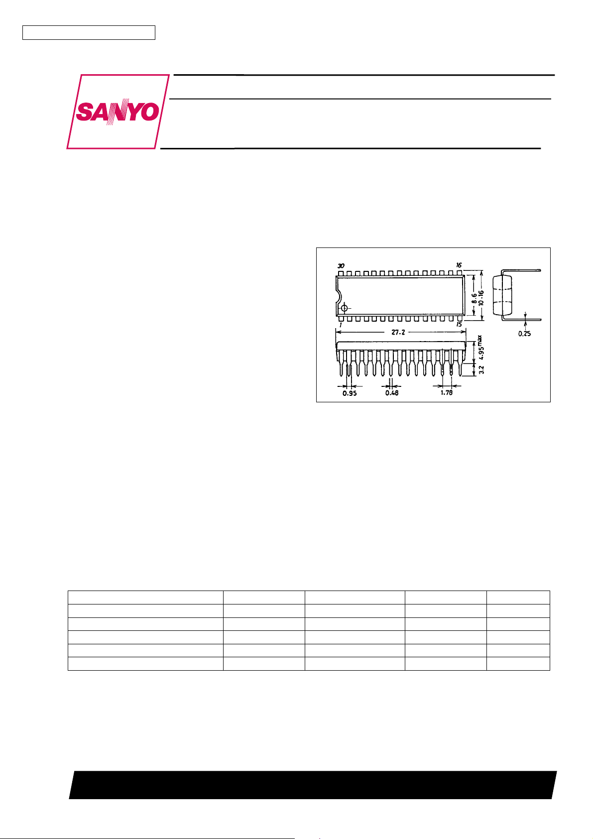
Package Dimensions
unit : mm
3061-DIP30S
[LA7625,7626]
SANYO : DIP30S
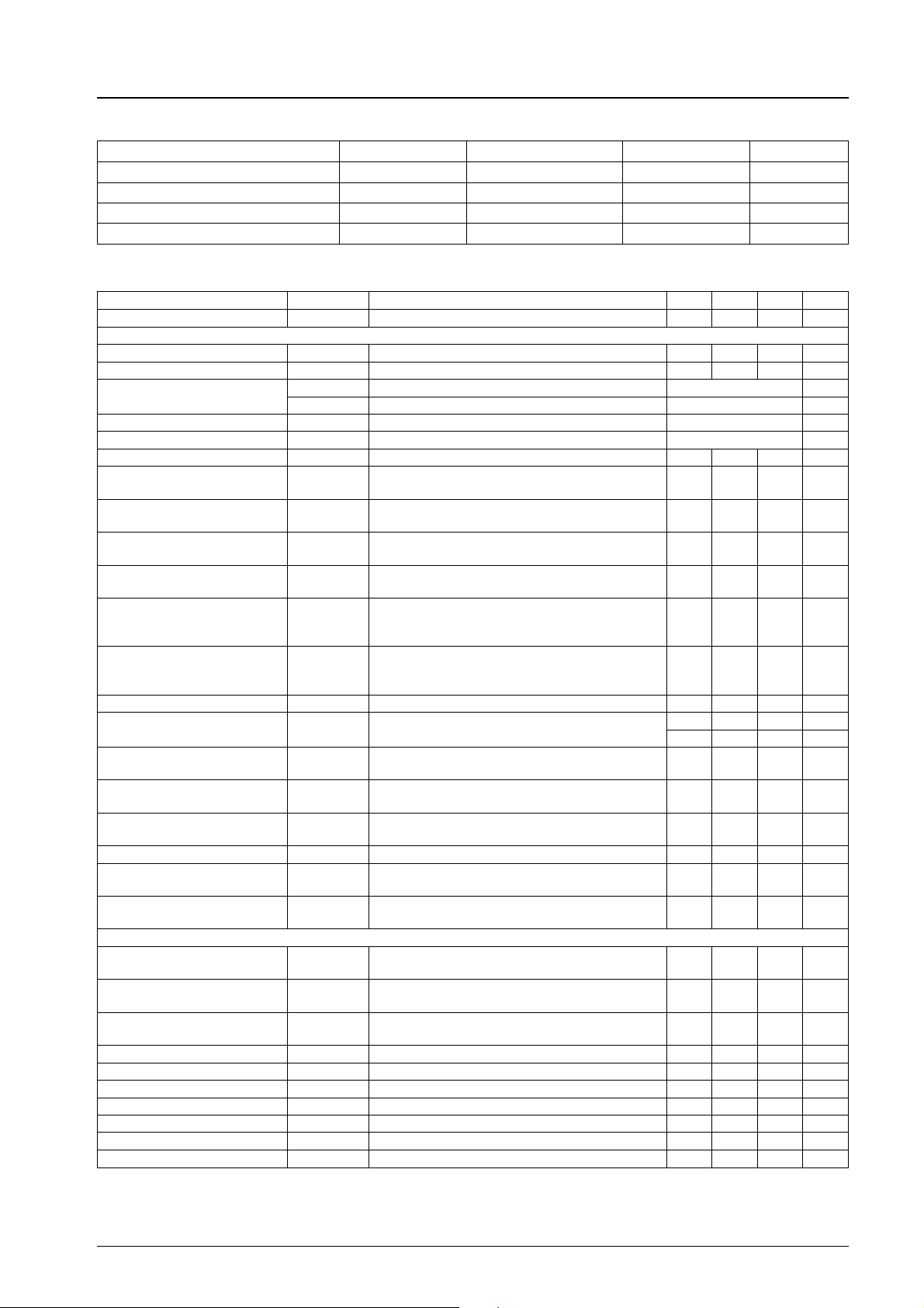
Specifications
Maximum Ratings atTa=25°C
Parameter Symbol Conditions Ratings Unit
Maximum supply voltage V
Maximum supply current I
Allowable power dissipation Pd max Ta % 65°C 1100 mW
Operating temperature Topr –20 to +85
Storage temperature Tstg –55 to +125
max 14.0 V
16
max 15.0 mA
22
SANYO Electric Co.,Ltd. Semiconductor Bussiness Headquarters
TOKYO OFFICE Tokyo Bldg., 1-10, 1 Chome, Ueno, Taito-ku, TOKYO, 110 JAPAN
62095HA (II) No.2289 - 1/6
C
°
C
°
Page 2
LA7625, 7626
Operating Conditions atTa=25°C
Parameter Symbol Conditions Ratings Unit
Recommended supply voltage V
Recommended supply current I
Operating supply voltage range V
Operating supply current range I
Electrical Characteristics atTa=25°C, VCC=V16=12V,ICC=I22=10mA
16
22
op 9.0 to 14.0 V
16
op 8.5 to 15.0 mA
22
12.0 V
10.0 mA
Parameter Symbol
Circuit current I
16
No signal 40 53 75 mA
Conditions
min typ max Unit
[Deflection block]
Horizontal supply voltage V
Sync separation input DC level V
Vertical free-running
frequency 1
Z22
S.S
f
1f
V
f
2f
V
Vertical blanking pulse width PW V.blk 19.25/f
Vertical output pulse width PW V.out 10.25/f
Vertical drive stage voltage gain G
Vertical output pulse start
voltage
Vertical pull-in operation start
voltage
Vertical blanking pulse wave
peak value
Horizontal free-running
frequency
V
Vcds 4.0 V
Vvps 4.0 V
VV.blk 10 V
f
H
Frequency deviation versus 15.734 kHz –70 0 130 Hz
8.2 8.7 9.2 V
9.0 9.3 9.6 V
/296.5 Hz
H
/224.5 Hz
H
H
H
s
s
13 16.2 19 dB
Dependence of horizontal
oscillation frequency on
supply voltage
∆ f
(V) fH(8V)–fH(7V) –10 0 10 Hz
H
Dependence of horizontal
oscillation frequency on
operating temperature
∆ f
/∆ TTa= –10°Cto60°C –1.5 1.5 Hz/deg
H
Horizontal output pulse width PW Hout 23.5 24.5 25.5 µs
Horizontal sync pull-in
frequency range
Horizontal output pulse start
voltage
Horizontal free-running
frequency drift with time
Hotizontal blanking
threshold level
Horizontal output drive current I
Horizontal oscillation control
sensitivity
Hold-down operation start
voltage
f
pull Differential versus 15.734 kHz
H
V
pos 5.5 V
H
∆ f
V
.blk 11 V
H
H.O
B
fH
V
HD
for 5 seconds to 30 minutes after power is applied –50 –10 30 Hz
HT
Reference value only (i.e. not specified) 236 Hz/µA
400 Hz
–500 Hz
2.0 4.5 mA
0.55 0.65 0.75 V
[Video block]
Video tone
control characteristics 1
Video tone
control characteristics 1
RE1
RE2
Video voltage gain AV
f = 2 MHz,
Video tone VR: 0 V
f = 2 MHz,
Video tone VR: 12 V
f = 100 kHz,
Video tone VR: 5.5 V
–5 –3 –1 dB
12 15 18 dB
12 15 18 dB
Contrast control center eo f = 100 kHz, input: 100 mVp-p 0.2 0.3 0.4 Vp-p
Contrast variable range ∆ eo f = 100 kHz 16 18 20 dB
Bright control characteristics 1 BR1 No signal, bright VR: 3 V 8 V
Bright control characteristics 2 BR2 No signal, bright VR: 6 V 5.8 6.3 6.8 V
Bright control characteristics 3 BR3 No signal, bright VR: 9 V 4.5 V
Frequency response f f = 5 MHz/f = 100 kHz –5 dB
DC restoration factor R
DC
STAIR STEP signal reference value 100 %
Continued on next page.
No.2289 - 2/6
Page 3

Continued from preceding page.
LA7625, 7626
Parameter Symbol
[Chroma Block]
ACC amplitude characteristics 1 ACC1 Input: +6 dB –3 0 +3 dB
ACC amplitude characteristics 2 ACC2 Input :–20 dB –7 +2 dB
ACC phase characteristics 1 ACC
ACC phase characteristics 2 ACC
Killer operating point EK –55 –46 –40 dB
Color control center B-Ycen Output B-Y: color VR 6 V 2.9 4.3 5.5 Vp-p
Maximum demodulation output B-Ymax Output B-Y: color VR 12 V 5.5 6.5 Vp-p
Color contrast variable range ∆ Gcont Output B-Y 15.5 17.0 18.5 dB
Tint center Tcen Output B-Y: tint VR 6 V –17 –5 +7 deg
Tint variable range ∆ T Output B-Y
APC pull-in range ∆ f APC ±300 Hz
Demodulation output ratio 1 R-Y/B-Y 0.81 0.90 0.98
Demodulation output ratio 2 G-Y/B-Y 0.24 0.30 0.38
Demodulation angle 1 ∠R-Y/B-Y Tint VR 6 V 96 104 112 deg
Demodulation angle 2 ∠R-Y/B-Y Tint VR 6 V –132 –122 –112 deg
Color difference output DC
voltage
Color difference output DC
deviation voltage
1 Input: +6 dB –3 +3 deg
ø
2 Input: –20 dB –7 +7 deg
ø
V9,10,11 6.7 7.2 7.7 V
∆ V9,10,11 –200 +200 mV
Conditions
min typ max Unit
+45
–35
deg
No.2289 - 3/6
Page 4

LA7625, 7626
Block Diagram of Equivalent Circuit Block and Examples of Peripheral Circuits
2nd
Countdown
1st
Countdown
X-ray
Protector
Hor.
Predriver
Unit (resistance: Ω, capacitance: F)
No.2289 - 4/6
Page 5

LA7625, 7626
Vertical output IC (LA7832, 7833) connection circuit example
Includes vertical stabilization circuit
Vertical output IC (LA7837, 7838) connection circuit example
Unit (resistance: Ω, capacitance: F)
↑
Vertical stabilization circuit
Unit (resistance: Ω)
The following family of color TV NTSC system Y, chroma, and deflection ICs has been developed, each with different functions
and characteristics. Select the IC that best suits the application and purpose for which the color TV set is intended.
Type number Peak clipping
LA7620 O 70% Positive polarity O O
LA7621 X 70% Positive polarity O O
LA7625 O 100% Positive polarity O O
LA7626 X 100% Positive polarity O O
LA7629 X 100% *Negative polarity X O Video band 10MHz
DC restoration
factor
Secondary differential
circuit input polarity
Video tone
Soft Sharp
Remarks
* : Requires inverting amplifier
No.2289 - 5/6
Page 6

LA7625, 7626
No products described or contained herein are intended for use in surgical implants, life-support systems, aerospace equipment,
nuclear power control systems, vehicles, disaster/crime-prevention equipment and the like, the failure of which may directly or
indirectly cause injury, death or property loss.
Anyone purchasing any products described or contained herein for an above-mentioned use shall:
1 Accept full responsibility and indemnify and defend SANYO ELECTRIC CO., LTD., its affiliates, subsidiaries and distributors
and all their officers and employees, jointly and severally, against any and all claims and litigation and all damages, cost and
expenses associated with such use:
2 Not impose any responsibility for any fault or negligence which may be cited in any such claim or litigation on SANYO
ELECTRIC CO., LTD., its affiliates, subsidiaries and distributors or any of their officers and employees jointly or severally.
Information (including circuit diagrams and circuit parameters) herein is for example only; it is not guaranteed for volume
production. SANYO believes information herein is accurate and reliable, but no guarantees are made or implied regarding its use
or any infringements of intellectual property rights or other rights of third parties.
This catalog provides information as of June, 1995. Specifications and information herein are subject to change without notice.
No.2289 - 6/6
 Loading...