

Page 1
Any and all SANYO products described or contained herein do not have specifications that can handle
applications that require extremely high levels of reliability, such as life-support systems, aircraft’s
control systems, or other applications whose failure can be reasonably expected to result in serious
physical and/or material damage. Consult with your SANYO representative nearest you before using
any SANYO products described or contained herein in such applications.
SANYO assumes no responsibility for equipment failures that result from using products at values that
exceed, even momentarily, rated values (such as maximum ratings, operating condition ranges,or other
parameters) listed in products specifications of any and all SANYO products described or contained
herein.
Monolithic Linear IC
Vertical Deflection Output Circuit
with Driver for Color TV Use
Ordering number:ENN2863
LA7835
SANYO Electric Co.,Ltd. Semiconductor Company
TOKYO OFFICE Tokyo Bldg., 1-10, 1 Chome, Ueno, Taito-ku, TOKYO, 110-8534 JAPAN
Overview
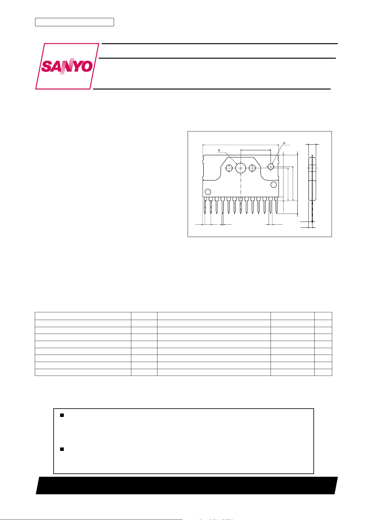
The LA7835 is an IC that contains the vertical deflection
output circuit with a driver for small-aperture (maximum
deflection current 1.8Ap-p) color/B&W TV, monitor/display use and is placed in a SIP13H package. The LA7835
has such features as greatly reduced number of external
parts and low power dissipation. Since both DC feedback
and AC feedback can be provided inside the IC, it is easy
to design the vertical deflection circuit. The LA7835 can
be used in conjunction with single-chip IC LA7650 (NTSC),
LA7680 series (PAL/NTSC) (VIF, SIF, video, chroma, and
deflection circuit) to provide all the functions required for
color TV signal processing.
Features
• Low power dissipation because of on-chip pump-up circuit.
• On-chip 50/60Hz vertical size control circuit.
• On-chip ramp generator.
• On-chip driver circuit.
• Vertical output circuit.
• On-chip thermal protection circuit.
• Minimum number of parts required.
Package Dimensions
unit:mm
3107-SIP13H
[LA7835]
25.6
3.4
1
2.00.8
0.5
10.0
2.0
13.9
11.8
11.2
1.0min
13
1.15
SANYO : SIP13H
2.4
15.4max
4.5
0.4
1.2
Specifications
Maximum Ratings at Ta = 25˚C
retemaraPlobmySsnoitidnoCsgnitaRtinU
V+
egatlovylppusrewoprevirD
egatlovylppusrewoppu-pmuP
egatlovylppusrewoptuptuO
tnerructuptuonoitcelfeDI
noitapissidrewopelbawollAxamdPknistaehetinifnihtiW 8W
erutarepmetgnitarepOrpoT 58+ot02–
erutarepmetegarotSgtsT 051+ot04–
ecnatsiserlamrehT
xam
1CC
V+
xam
7CC
V+
xam
21CC
FED
θ c-j
12501TN (KT)/90196RM No.2863–1/5
51V
03V
26V
5.1+ot5.1–o-pA
˚C
˚C
˚C/W
4
Page 2
Operating Supply Voltage Conditions
retemaraPlobmySsnoitidnoCsgnitaRtinU
egatlovylppusrevirDV+
egatlovylppuspu-pmuPV+
Recommended Operating Conditions
retemaraPlobmySsnoitidnoCsgnitaRtinU
egatlovylppusrevirDV+
egatlovylppuspu-pmuPV+
tnerructuptuonoitcelfeDI
LA7835
1CC
7CC
1CC
7CC
p-p11
41ot8V
72ot01V
21)9(V
42V
8.1otpup-pA
Operating Characteristics at Ta = 25˚C, +V
retemaraPlobmySsnoitidnoC
tnerructnecseiuqylppusrewoprevirDI
egatlovdlohserhttupnireggirTV
egatlovniplortnocezislacitreVV
egatlovtratsepahsmrofevawpmaRV
egatlovnoitarutasegrahcpu-pmuPV
egatlovnoitarutasegrahcsidpu-pmuPV
)rewol(egatlovnoitarutastuptuonoitcelfeDV
)reppu(egatlovnoitarutastuptuonoitcelfeDV
tnerrucgnildI 612223Am
niagegatloVGV
1CC
2
3
PMAR
01-8S
8-7S
O
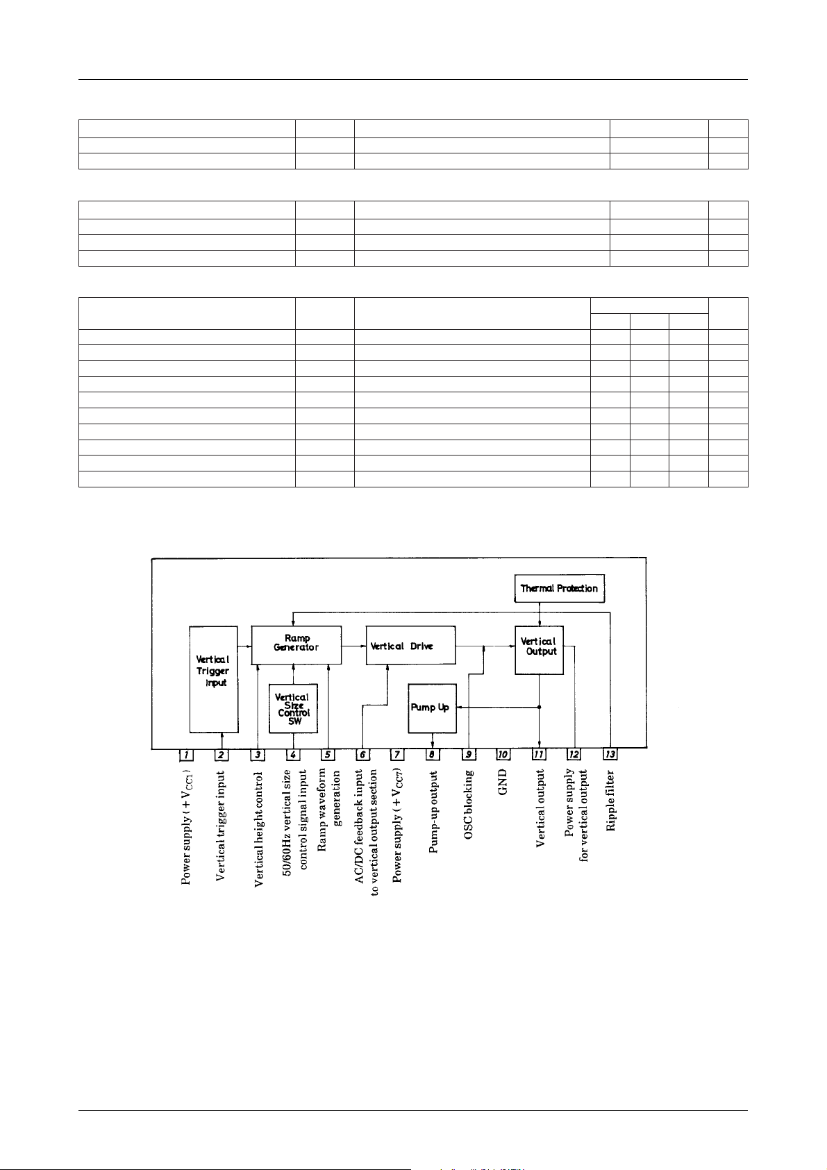
Pin Assignment and Block Diagram
CC1
01-11S
11-21S
=12V, +V
A9.0=I 0.3V
A9.0=I 2.1V
A9.0=I 2.3V
zHk1=f95Bd
CC7
=24V
sgnitaR
nimpytxam
8.18.28.3Am
8.21.34.3V
9.51.63.6V
7.40.53.5V
5.1V
tinU
No.2863–2/5
Page 3
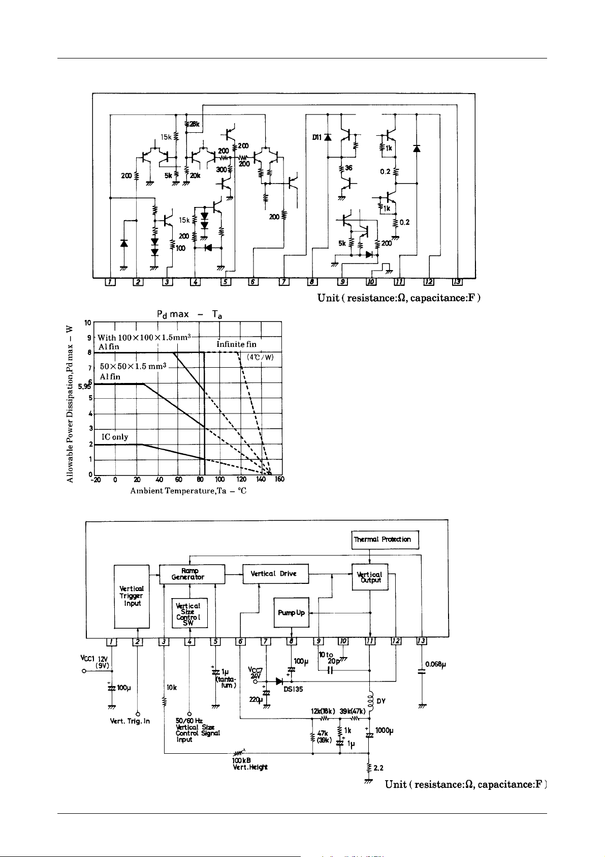
Equivalent Circuit
LA7835
Sample Application Circuit
Note) The values in parentheses are for a sample application where the V
CC1
is 9V.
No.2863–3/5
Page 4
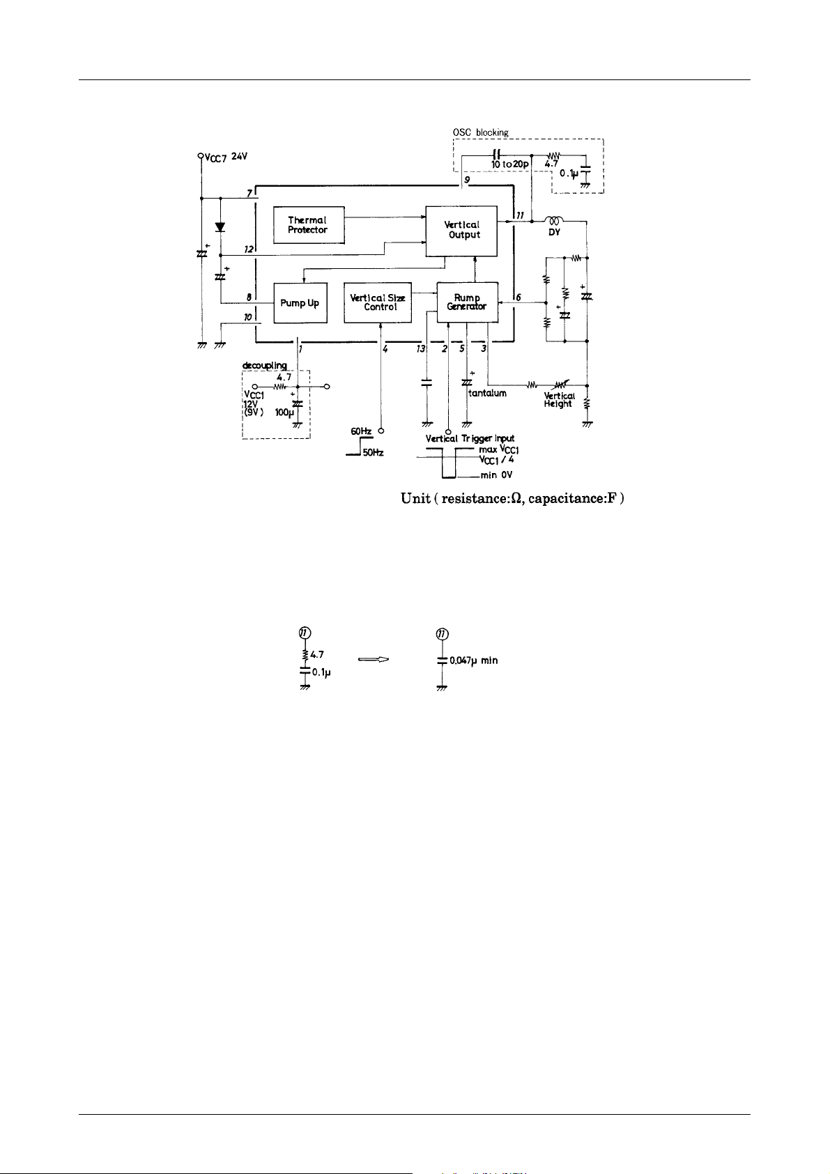
Proper Cares in Using the LA7835
LA7835
Note 1) If horizontal components are mixed into pin 1, causing the interlace characteristic to worsen, provide
decoupling as shown above. The resistor value and capacitor value are shown as an example.
2) If oscillation occurs, connect the OSC blocking circuit as shown above.
However, if the deflection current increases, oscillation may not be blocked completely. In this case, change
the application circuit as shown below.
3) In some applications, the OSC blocking capacitor across pins 9 and 11 is connected across pin 9 and GND.
4) The threshold voltage on pin 2 is +V
1/4. Set the input trigger level so that it intersects this threshold level.
CC1
The LA7835 operates on the negative transition of the trigger pulse.
5) Connect the radiator fin to GND.
No.2863–4/5
Page 5
LA7835
Specifications of any and all SANYO products described or contained herein stipulate the performance,
characteristics, and functions of the described products in the independent state, and are not guarantees
of the performance, characteristics, and functions of the described products as mounted in the customer's
products or equipment. To verify symptoms and states that cannot be evaluated in an independent device,
the customer should always evaluate and test devices mounted in the customer's products or equipment.
SANYO Electric Co., Ltd. strives to supply high-quality high-reliability products. However, any and all
semiconductor products fail with some probability. It is possible that these probabilistic failures could
give rise to accidents or events that could endanger human lives, that could give rise to smoke or fire,
or that could cause damage to other property. When designing equipment, adopt safety measures so
that these kinds of accidents or events cannot occur. Such measures include but are not limited to protective
circuits and error prevention circuits for safe design, redundant design, and structural design.
In the event that any or all SANYO products(including technical data,services) described or
contained herein are controlled under any of applicable local export control laws and regulations,
such products must not be exported without obtaining the export license from the authorities
concerned in accordance with the above law.
No part of this publication may be reproduced or transmitted in any form or by any means, electronic or
mechanical, including photocopying and recording, or any information storage or retrieval system,
or otherwise, without the prior written permission of SANYO Electric Co. , Ltd.
Any and all information described or contained herein are subject to change without notice due to
product/technology improvement, etc. When designing equipment, refer to the "Delivery Specification"
for the SANYO product that you intend to use.
Information (including circuit diagrams and circuit parameters) herein is for example only ; it is not
guaranteed for volume production. SANYO believes information herein is accurate and reliable, but
no guarantees are made or implied regarding its use or any infringements of intellectual property rights
or other rights of third parties.
This catalog provides information as of January, 2001. Specifications and information herein are subject
to change without notice.
PS No.2863–5/5
 Loading...