

Page 1
Ordering number: EN2781B
Monolithic Linear IC
LA7852
CRT Display Synchronization Deflection Circuit
Overview
The LA7852 is a sync-deflection circuit IC dedicated to CRT
display use. It can be connected to the LA7832/7833, 7837/
7838 (for vertical output use) to form a sync-deflection circuit
that meets every requirement for CRT display use.
So far, ICs for color TV use have been applied to the syncdeflection circuit for CRT display use, and general-purpose ICs
such as one-shot multivibrator, inverter and a lot of transistors
have been used to form the peripherals such as sync input
interface, horizontal phase shifter. The LA7852 contains these
peripherals on chip and adopts a stable circuit for horizontal
oscillation from 15 kHz to 100 kHz aiming at improving the
characteristics required for CRT display use.
The LA7852 has independent GND pins for the horizontal
block and vertical block, thus facilitating pattern layout for
applications where the LA7852 is used at high frequencies.
Features
.
The vertical pull-in range is approximately 10 Hz at
fv = 60 Hz.
.
The horizontal oscillation frequency can be adjusted stably
from 15 kHz to 100 kHz.
.
The horizontal display can be shifted right/left.
.
The horizontal/vertical sync input can be used intact
regardless of the difference in pulse polarity and pulse width.
.
The AFC feedback sawtooth wave can be obtained by
simply applying a flyback pulse to the IC as a trigger pulse.
.
Any duty of the horizontal pulse can be set.
.
Good vertical linearity because DC bias at vertical output
stage is subjected to sampling control within retrace time.
.
Excellent interlace and vertical jitter characteristics on the
high-definition display because of independent GND pins for
the horizontal block and vertical block.
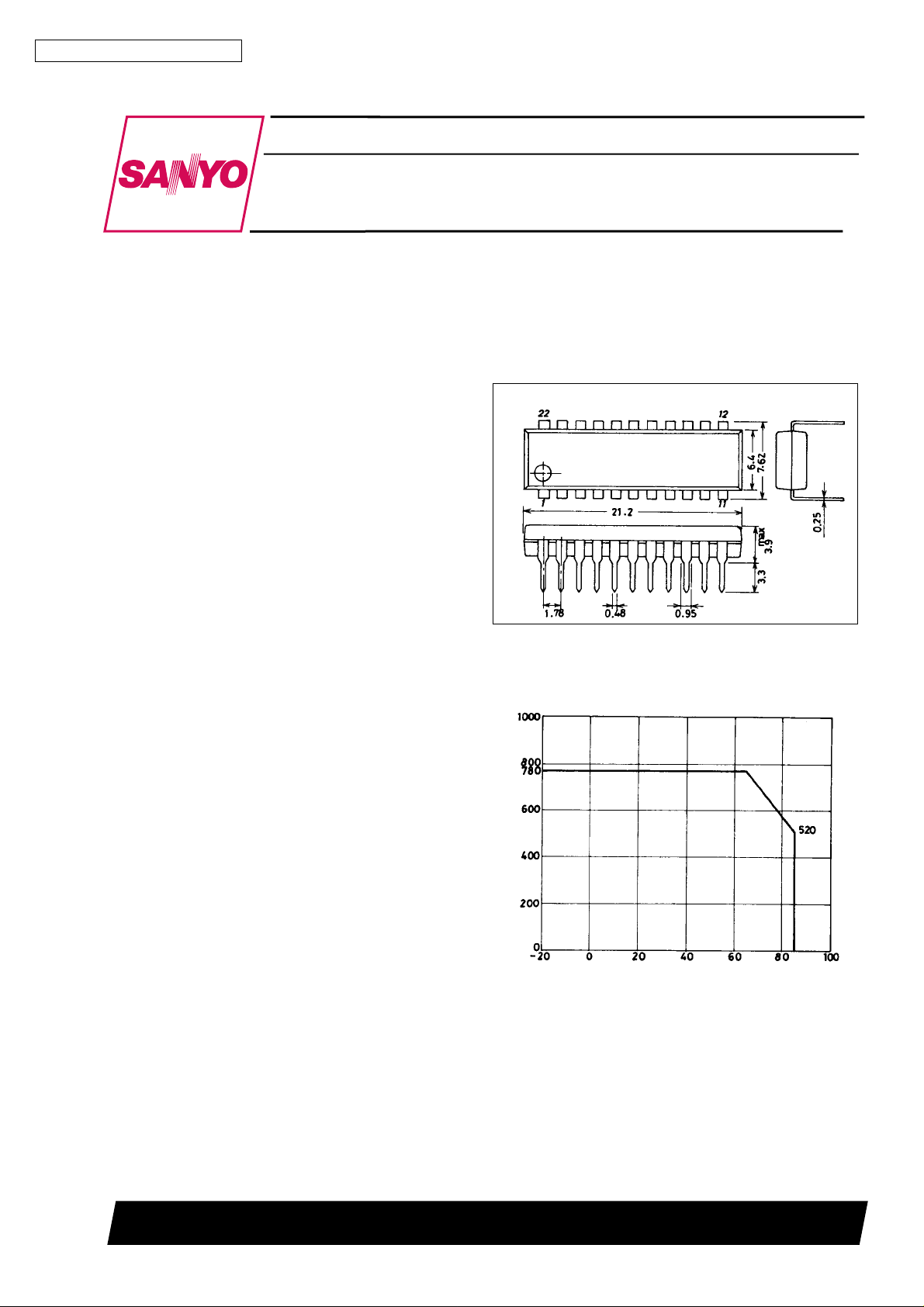
Package Dimensions
unit : mm
3059-DIP22S
[LA7852]
SANYO : DIP22S
Pd max – Ta
Allowable power dissipation, Pd max – mW
Ambient temperature, Ta – °C
Built-in Functions
[Horizontal Block]
.
AFC
.
Horizontal OSC
.
X-ray protector
.
Horizontal phase shift
.
AFC sawtooth wave generator
.
Horizontal pulse duty setting
[Vertical Block]
.
Vertical OSC
.
Vertical sawtooth wave generator
.
Sampling type DC voltage control
SANYO Electric Co.,Ltd. Semiconductor Bussiness Headquarters
TOKYO OFFICE Tokyo Bldg., 1-10, 1 Chome, Ueno, Taito-ku, TOKYO, 110 JAPAN
81096HA(II)/9138YT/8228YT,TS No.2781-1/5
Page 2
LA7852
Specifications
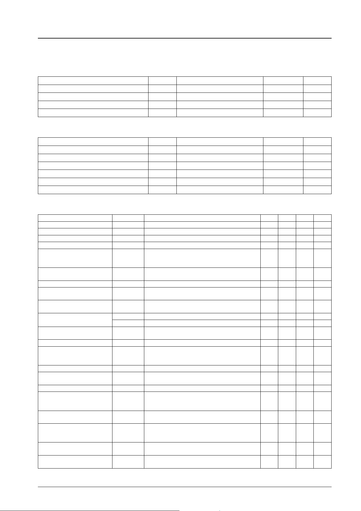
Maximum Ratings at Ta = 25°C
Parameter Symbol Conditions Ratings Unit
Maximum supply voltage V
11,V22
Allowable power dissipation Pd max Ta % 65° C 780 mW
Operating temperature Topr –20 to +85 °C
Storage temperature Tstg –55 to +125 °C
Operating Conditions at Ta = 25°C
Parameter Symbol Conditions Ratings Unit
Recommended supply voltage V
Operating voltage range V
Recommended vertical pulse input peak value V
Operating vertical pulse input peak value range V
Recommended horizontal pulse input peak value H
Operating horizontalpulse input peak value range H
11,V22
11,V22
PULSE
PULSE
PULSE
PULSE
Operating Characteristics at Ta = 25°C, V11,V22=12V
14 V
12 V
9 to 13.5 V
5 Vp-p
2 to 6 Vp-p
5 Vp-p
2 to 6 Vp-p
Parameter Symbol Conditions min typ max Unit
V
current dissipation I
CC11
V
current dissipation I
CC22
Vertical frequency pull-in range Vp
11
22
Vertical sync 60 Hz 10.0 12.0 Hz
IN
12 30 mA
512mA
Vertical free-running frequency fv fv center 55 Hz 50 60 Hz
Increased/reduced voltage
characteristic of vertical
frequency
Midpoint control
threshold level
∆fv-v V
=12±1 V, 55 Hz at 12 V –0.1 +0.1 Hz
22
3.8 4.4 V
Vertical OSC start voltage Fvcst 4.0 V
Temperature characteristic of
vertical frequency
Vertical driver
amplification factor
Horizontal AFC DC loop gain
Horizontal free-running
frequency
Horizontal OSC start voltage f
Gv 12 18 dB
I
AFC
I
AFC
f
H
H
Ta = –10 to +60°C –0.028 +0.028 Hz/°C
+ 0.85 1.6 mA
– –1.6 –0.85 mA
fHcenter 15.734 kHz –750 +750 Hz
cst 4.0 V
Increased/reduced voltage
characteristic of horizontal
frequency
Horizontal OSC warm-up drift ∆f
Temperature characteristic of
horizontal frequency
Horizontal output drive current I
∆f
cvV11=12±1 V, 15.734 kHz at 12 V –50 +50 Hz
H
5 s to 30 min. after application of power –50 +50 Hz
H
Ta = –10 to +60°C –2.9 +2.9 Hz/°C
13
6.0 12.0 mA
Increased/reduced voltage
characteristic of phase shifter
delay time
Temperature characteristic of
phase shifter delay time
V
=12±1 V –0.5 +0.5 %/V
11
Ta = –10 to +60°C –0.1 +0.1 %/°C
Increased/reduced voltage
characteristic of phase shifter
delay time
Temperature characteristic of
phase shifter pulse width
AFC phase comparison center
time
V
=12±1 V –1.0 +1.0 %/V
11
Ta = –10 to +60°C –0.13 +0.13 %/°C
15.734 kHz after FBP input 9.9 11.5 µs
No.2781-2/5
Page 3
Parameter Symbol Conditions min typ max Unit
Increased/reduced voltage
characteristic of AFC phase
comparison center time
Temperature characteristic of
AFC phase comparison center
time
Comparison waveform
generating
input operation voltage
Pin 14 voltage at hold-down
operation start
V
5
V
14
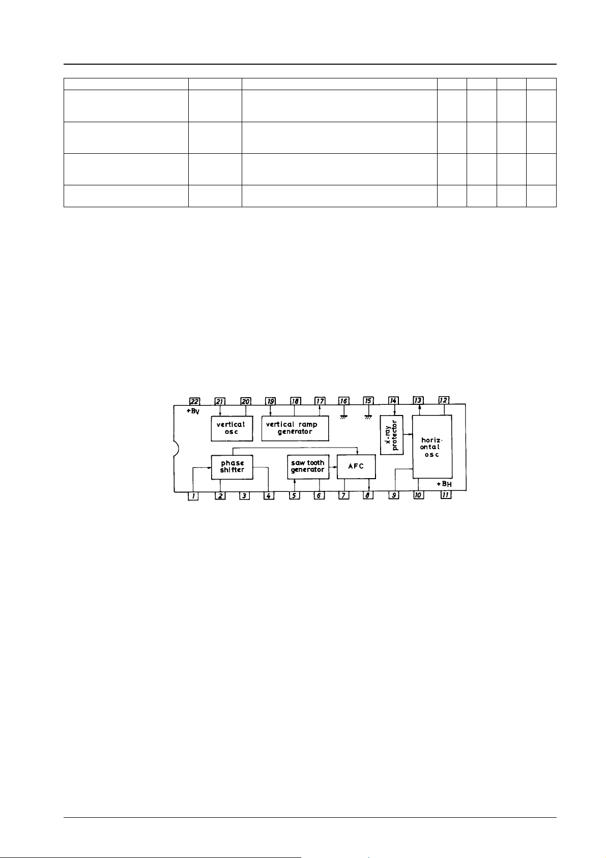
Equivalent Circuit Block Diagram
LA7852
V
=12±1 V –1.5 +1.5 %/V
11
Ta = –10 to +60°C –0.2 +0.2 %/°C
0.6 0.9 V
0.5 0.8 V
Vertical power supply
Horizontal trigger input
Vertical OSC time constant
Vertical trigger input
NC
Phase adjust time constant
Midpoint voltage control input
time constant
Sync pulse width
Vertical sawtooth wave
generation
Sawtooth wave
FBP trigger input
Vertical drive output
Vertical ground
Comparison voltage
generating capacitor
Horizontal ground
AFC output
generating capacitor
X-ray protection input
time constant
Horizontal OSC
Horizontal drive output
Discharge resistor
Horizontal drive
pulse width setting
Horizontal power supply
No.2781-3/5
Page 4
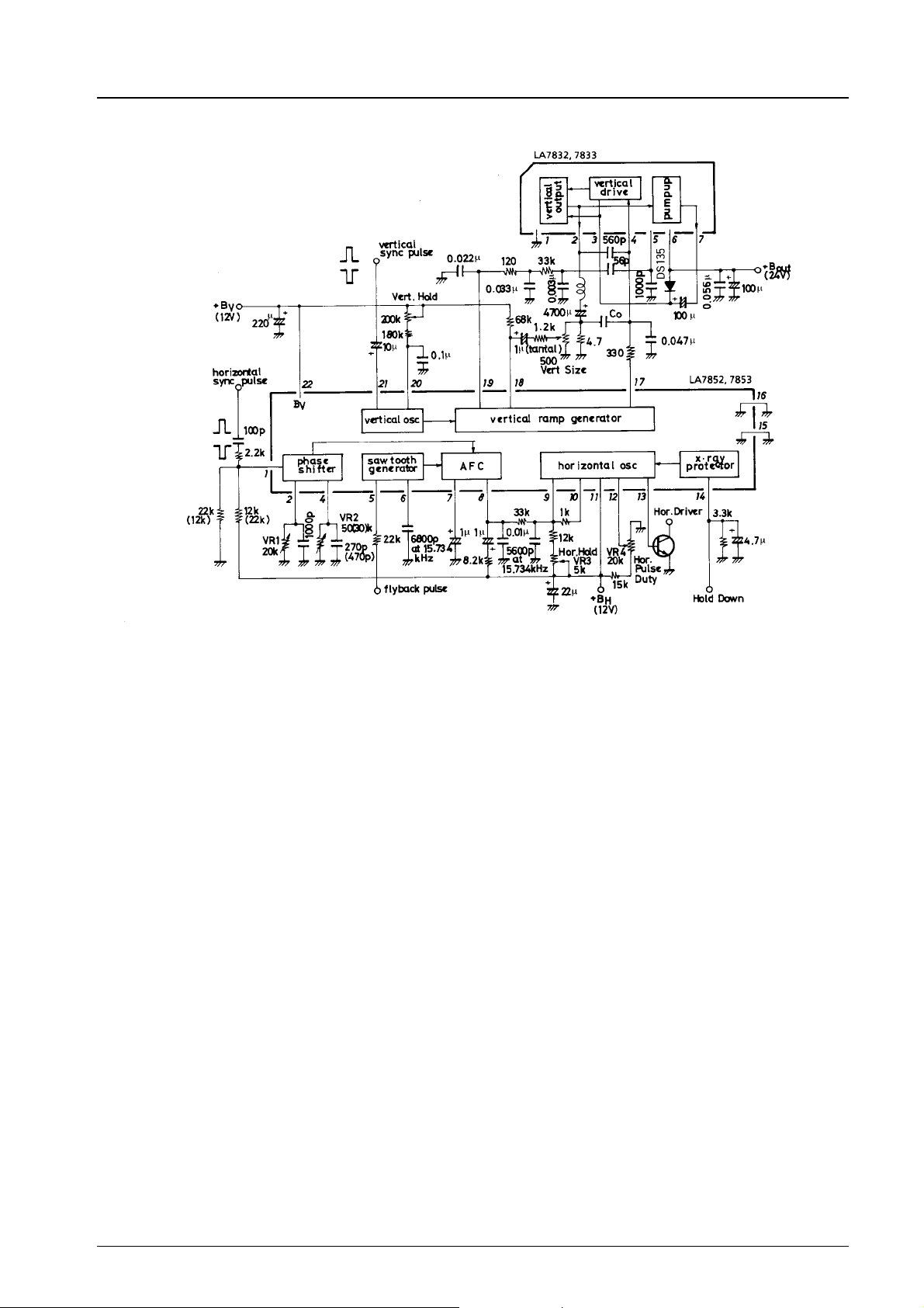
Sample Application Circuit
14’’ Color Monitor / fv = 60 Hz, fH= 15.734 kHz
LA7852
(Note)
Co is connected when
oscillation occurs in vertical
output in Sample Application
Circuit.
( ): Negative pulse
mode
VR2 is fixed after adjustment.
(Note) For the LA7853, the vertical pull-in range is
20 Hz at vertical sync 60 Hz.
Unit (resistance: Ω, capacitance: F)
No.2781-4/5
Page 5

Sample Application Circuit
14’’ Color Monitor / fv = 60 Hz, fH= 15.734 kHz
( ): Negative pulse mode
LA7852
VR2 is fixed after adjustment
LA7850 Family
Type Number LA7850 LA7851 LA7852 LA7853
Package DIP-20S
Differences in
characteristics
No products described or contained herein are intended for use in surgical implants, life-support systems, aerospace equipment,
nuclear power control systems, vehicles, disaster/crime-prevention equipment and the like, the failure of which may directly or
indirectly cause injury, death or property loss.
Anyone purchasing any products described or contained herein for an above-mentioned use shall:
1 Accept full responsibility and indemnify and defend SANYO ELECTRIC CO., LTD., its affiliates, subsidiaries and distributors
and all their officers and employees, jointly and severally, against any and all claims and litigation and all damages, cost and
expenses associated with such use:
2 Not impose any responsibility for any fault or negligence which may be cited in any such claim or litigation on SANYO
ELECTRIC CO., LTD., its affiliates, subsidiaries and distributors or any of their officers and employees jointly or severally.
Information (including circuit diagrams and circuit parameters) herein is for example only; it is not guaranteed for volume
production. SANYO believes information herein is accurate and reliable, but no guarantees are made or implied regarding its use
or any infringements of intellectual property rights or other rights of third parties.
Vertical
pull-in range
(fv = 60 Hz)
Ground pin Horizontal/vertical
(Slim Type)
10 Hz 20 Hz 10 Hz 20 Hz
common
DIP-20S
(Slim Type)
horizontal/vertical
common
DIP-22S
(Shrink Type)
Horizontal/vertical
separated
DIP-22S
(Shrink Type)
Horizontal/vertical
separated
A05903
This catalog provides information as of August, 1996. Specifications and information herein are subject to change without notice.
No.2781-5/5
 Loading...