


 Loading...
M-Series
Quick Reference Guide
Publication Number 821003573 Rev C

Compliance
Datalogic S.r.l. makes no representations or warranties for merchantability or fitness for any particular purpose, regarding Datalogic’s software or hardware. Datalogic S.r.l. shall not be liable for errors contained herein or for incidental or consequential damages in connection with the furnishing, performance, or use of this publication or its contents.
Datalogic S.r.l. reserves the right to revise this publication from time to time and to make changes in the content hereof without obligation to notify any person of such revision or changes.
Datalogic S.r.l. Via S. Vitalino 13
40012 Calderara di Reno - Italy http://www.datalogic.com mvsupport@datalogic.com
© 2014 - 2017 Datalogic S.p.A. and/or its affiliates All rights reserved. Without limiting the rights under copyright, no part of this documentation may be reproduced, stored in or introduced into a retrieval system, or transmitted in any form or by any means, or for any purpose, without the express written permission of Datalogic S.p.A. and/or its affiliates. Datalogic and the Datalogic logo are registered trademarks of Datalogic S.p.A. in many countries, including the U.S. and the E.U. Impact, P-Series, Vision Program Manager (VPM), Pinpoint Pattern Find, and Control Panel Manager (CPM) are trademarks of Datalogic S.p.A. and/or its affiliates, registered in many countries, including the U.S. and the E.U. All other trademarks and brands are property of their respective owners.
Patent
See www.patents.datalogic.com for patent list.
This product is covered by one or more of the following patents: Utility patents: US6,512,218 B1; US6,616,039 B1; US6,808,114 B1; US6,997,385 B2; US7,053,954 B1; US7,387,246 B2; US8,058,600 B2; EP996,284 B1; EP999,514 B1; EP1,014,292 B1; EP1,128,315 B1; EP1,396,811 B1; EP1,413,971 B1; JP4,435,343 B2; JP4,571,258 B2.EAC COMPLIANCE
EACCOMPLIANCE
Customs Union:
The CU Conformity certification has been achieved; this allows the Product to bear the Eurasian mark of conformity.
CECompliance
CE marking states the compliance of the product with essential requirements listed in the applicable European directive. Since the directives and applicable standards are subject to continuous updates, and since Datalogic promptly adopts these updates, therefore the EU declaration of conformity is a living document. The EU declaration of conformity is available for competent authorities and customers through Datalogic commercial reference contacts. Since April 20th, 2016 the main European directives applicable to Datalogic products require inclusion of an adequate analysis and assessment of the risk(s). This evaluation was carried out in relation to the applicable points of the standards listed in the Declaration of Conformity. Datalogic S.r.l. products are mainly designed for integration purposes into more complex systems. For this reason it is under the responsibility of the system integrator to do a new risk assessment regarding the final installation.
Warning
This is a Class A product. In a domestic environment this product may cause radio interference in which case the user may be required to take adequate measures.
SupportThroughTheWebsite
Datalogic provides several services as well as technical support through its website. Log on to www.datalogic.com and click on the SUPPORT > Machine Vision category link. From this page you can select your product model from the dropdown list which gives you access to:
•Downloads including Data Sheets, Manuals, Software & Utilities, and Drawings;
•Repair Program for On-Line Return Material Authorizations (RMAs) plus Repair Center contact information;
•Service Program containing details about Maintenance Agreements;
•Technical Support through email or phone.
M-Series Quick Reference Guide |
Introduction |
Introduction
Thank you for using Datalogic M-Series vision system. This guide provides a brief overview to help you get started with your new system. For more detailed instructions, please refer to the Reference Guide (843-0093) and the M-Series Processor and Camera Guide (843-0148). It is important that you note the cautions and warnings in these manuals.
Safety Precautions
Warning: There are no user-serviceable parts inside the Datalogic hardware. To avoid electrical shock, never open the case. Opening the case or removing the tamper-proof sticker will void the product warranty.
Avertissement: Il n'y a aucune partie utilisateur-utile à l'intérieur du matériel d'Datalogic. Pour éviter le choc électrique, n'ouvrez jamais la valise. L'ouverture de la valise ou l'élimination de l'autocollant inaltérable videra la garantie de produit.
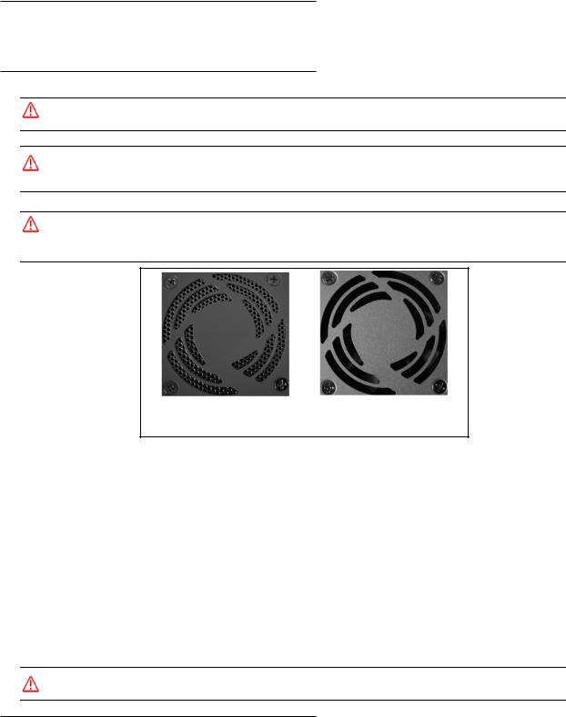
Mounting Warning: Mount the processor with the front or back of the unit facing down. For safety, do NOT mount the processor with the filter side down. Mounting with the fan side down is acceptable only if approved metal screen filters have been installed in all fan exhausts.
Metal Screen Filter Installed |
Metal Screen Filter NOT Installed. |
|
Do NOT mount fan side down |
•Read all of the following instructions before setting up your system. Save this document for later use.
•Follow all warnings and instructions in this manual and in other user guides shipped with your hardware components.
•To avoid damage to the vision system and its components, never plug in or unplug a cable when the power is on. Always turn off the power supply before you make cable changes.
•Never use the system if a power cable has been damaged. Do not allow anything to rest on a power cable and keep them away from traffic.
•The air inlets and exhausts on the top and sides of the unit are for ventilation. Do not block or cover these openings or insert anything into these openings. Metal screen filters may be installed in the fan exhausts.
•Do not expose the vision system to moisture, rain, or snow, and do not use it near water. If a component gets wet unplug it.
•To avoid injury, never open the case. Opening the case or removing the tamper-proof sticker will void the product warranty.
Service Personnel Only - Caution: Risk of explosion if battery is replaced by an incorrect type. Dispose of used batteries according to battery maker’s instructions.
Unpack the M-Series Hardware
When your system arrives, check the shipping cartons for wrinkled or damaged corners, holes through the cardboard, or other signs of rough handling or abuse. If you find any signs of damage, ask the delivery service to make a note on the delivery receipt describing the damage.
Page 1 |
Datalogic S.r.l.. |

Processor Specifications |
M-Series Quick Reference Guide |
Carefully remove the system unit, cameras, cabling, and accessories from the shipping package. Place all equipment you unpack on a table and inspect each item. Report any damage to the carrier immediately. Save all packing materials so you can repack the shipment in case you need to move or ship it.
Temperature precautions: If your system arrives in very cold or hot weather, allow all the equipment to reach room temperature before plugging it in. Exposing a cold device to a warm room causes condensation that could damage the system if power is applied too soon. If condensation forms, wait for it to dry completely.
Processor Specifications
This section lists the general operating specifications for the M-Series Processors.
Processor Operating Environment
Model |
MX20** and MX40 |
|
|
MX80 |
|||
|
|
|
|
|
|
||
Dimensions |
7.8 w x 3.3 h x 6.5 d (in) |
9.06 w x 3.23 h x 8.11 d (in) |
|||||
|
200 w x 85 h x 165 d (mm) |
230 w x 82 h X 206 d (mm) |
|||||
|
|
|
|
|
|
|
|
Weight |
4.8 lb. (2.16 kg) |
|
6.61 lb. (3 kg) |
|
|
||
|
|
|
|
|
|
|
|
Input Power* |
|
|
|
|
|
|
|
10 to 30VDC |
, Max. 10A; Min 3.5A |
10 to 30VDC |
|
, Min 5A |
|||
|
|
||||||
|
|
|
|
|
|
||
Temperature |
0° to +55° C (+32° to +131° F) |
0° to +55° C (+32° to +131° F) |
|||||
Humidity |
0% to 90% (non-condensing) |
0% to 90% (non-condensing) |
|||||
|
|
|
|
|
|
||
Safety |
CE/FCC, RoHs, IP30, UL |
CE/FCC, RoHs, IP30, UL |
|||||
Compliance |
(MX20 UL Pending) |
|
|
|
|
||
|
|
|
|
|
|
|
|
Minimum Soft- |
MX20 - 10.5.0 |
|
10.4.0 |
|
|
||
ware Version |
MX40 - 10.0.0 |
|
|
|
|
||
|
|
|
|
|
|
|
|
*NOTE: The MX20 and MX40 processors require approximately 3.5A @ 24VDC. Datalogic recommends using a 24 VDC power supply capable of providing 3.5A current. The M-Series processors run most efficiently at this voltage which is commonly used in many manufacturing environments.
The MX80 processor requires approximately 5A @ 24VDC. Datalogic recommends using a 24 VDC power supply capable of providing 5A current. This voltage is commonly used in many manufacturing environments.
**The MX20 processor can accommodate a maximum of two cameras. The maximum image size of each camera is two Megapixels. (The calculation is: maximum width in pixels * maximum height in pixels < 2,500,000.)
Installing Impact Software
NOTE: The M Device Software is intended for installation only on a Datalogic M-Series processor. You must install it directly on the processor you intend to use. You cannot install it remotely.
When a new processor is powered on the first time, a monitor, keyboard, and mouse must be connected to the processor to approve the license agreement.
All the required software was installed on the M-Series processor at the factory. If you want to change the system configuration, you will need to connect an optional monitor, mouse, and keyboard to the processor. For more details, refer to the M-Series Hardware Guide and Impact Reference Guide. If your system does not work when you are finished with the setup, review the instructions and diagrams to make sure you made all connections properly.
Resetting the M-Series Processor
To reset the M-Series Processor, press the Reset button on the processor’s front panel. See “MX20 and MX40 Front Panel Connections” on page 8 and “MX80 Front Panel Connections” on page 9.
Changing the Camera’s IP Address
1.Connect to the device with VPM.
2.Select the Settings tab.
3.Click the General System Object.
4.Select the General radio button.
5.Enter the desired IP address in the IP Address field.
Datalogic S.r.l. |
Page 2 |

M-Series Quick Reference Guide |
Changing the M-Series Processor’s IP Address (Windows XP) |
6.Press the Tab key.
7.When the Reboot dialog is displayed, click OK.
Changing the M-Series Processor’s IP Address (Windows XP)
IMPORTANT NOTE: Change only the Local Area Connection named LAN1 or LAN2. These correspond to Ethernet Ports 1 and 2 on the front of the processor.
DO NOT change any of the other Local Area Connections. Changing any other connection can cause the M-Series cameras to stop functioning.
1.In the Start menu, right click on My Network Places and select Properties.
2.Right click Local Area Connection LAN1 or LAN2 and select Properties.
3.On the General tab, select Internet Protocol (TCP/IP) and click Properties.
4.On the General tab, select Use the following IP address.
5.Enter the desired IP address.
6.Click OK to close all the open dialog windows.
Changing the M-Series Processor’s IP Address (Windows 7)
IMPORTANT NOTE: Change only the Local Area Connection named LAN1 or LAN2. These correspond to Ethernet Ports 1 and 2 on the front of the processor.
DO NOT change any of the other connections. Changing any other connection can cause the M-Series cameras to stop functioning.
1.In the Start menu, click on Control Panel.
2.Under Network and Internet, click on View Network Status and Tasks.
3.On the left side of the screen, click Change Adapter Settings.
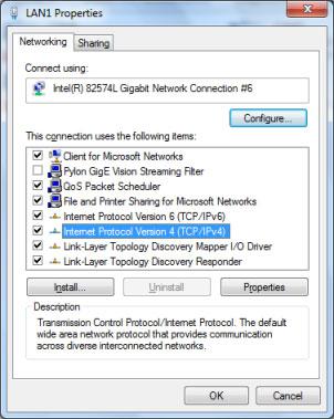
4. Right click LAN1 or LAN 2 and select Properties.
Page 3 |
Datalogic S.r.l. |
Changing the M-Series Processor’s IP Address (Windows 7) |
M-Series Quick Reference Guide |
5. In the list of items, select Internet Protocol Version 4 (TCP/IPv4), then click Properties.
6.Select Use the following IP address.
7.Enter the desired IP address.
8.Click OK to close all the open dialog windows.
Datalogic S.r.l. |
Page 4 |
M-Series Quick Reference Guide Flat Surface Mounting
Flat Surface Mounting
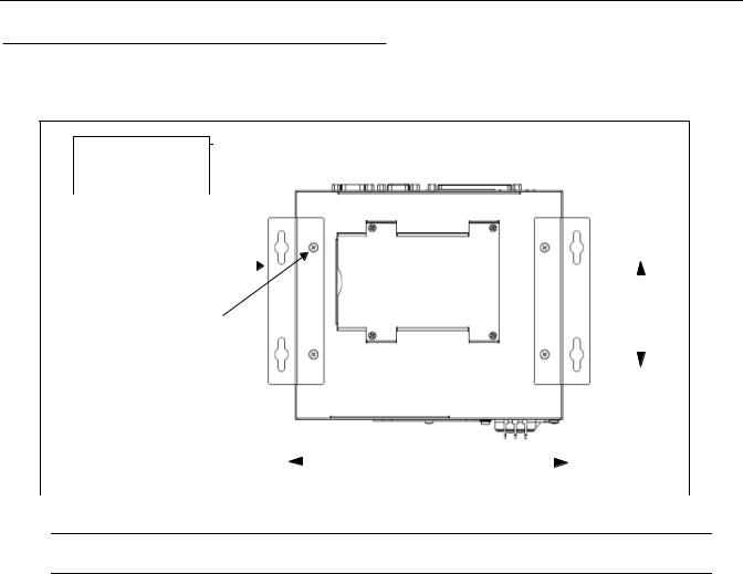
The M-Series Processor may be mounted on any stable surface using the provided case mounting brackets. (Use the appropriate bracket for the Processor model.) Allow at least 1.5 inches (38.1 mm) of clearance at the sides and top of the unit.
IMPORTANT: See Mounting Warning on Page 1
|
|
Bottom View |
|
|
|
|
Processor front |
|
||||
|
|
Mounting Hole |
|
|
|
|
|
|||||
|
|
|
|
|
|
|
|
|
|
|
|
|
|
|
Dimensions |
|
|
|
|
|
|
|
|
|
|
|
|
|
|
|
|
|
|
|
|
|
|
|
|
|
Mounting Brackets (x2) |
|
|
|
|
|
|
|
|
|
|
|
|
Provided |
|
|
|
|
|
|
|
|
|
|
|
|
|
|
|
|
|
|
|
|
|
|
|
Bracket Mounting Screws (x4) |
|
|
|
|
|
|
|
|
|
|||
|
|
|
|
|
|
All models |
|
|||||
M4, 0.7 mm pitch, 5 mm length - |
|
|
|
|
|
|
|
|||||
3.2 [80.0] |
|
|||||||||||
|
|
Provided |
|
|||||||||
|
|
|
|
|
|
|
|
|
|
|
||
|
|
|
|
|
|
|
|
|
|
|
||
|
|
UNITS: inch [mm.] |
|
|
|
|
|
|
|
|
|
|
|
|
|
|
|
|
|
|
|
|
|
||
|
|
|
|
|
|
|
|
|
|
|
||
Flat Surface Mounting |
|
|
|
|
|
|
|
|
|
|||
|
|
(Front Up) |
|
|
|
MX20; MX40=8.7 [221] |
|
|
|
|
|
|
|
|
|
|
|
|
|
MX80 =9.92 [252] |
|
||||
|
|
|
|
|
|
|||||||
|
|
|
|
Mounting Bracket Installation |
|
|||||||
NOTE: If the Processor uses a Compact Flash card, mount with the Processor front facing upward so the CF card does not fall out due to vibration.
To mount the Processor using the mounting brackets:
1.Fasten the two mounting brackets to the bottom of the Processor using the bracket mounting screws.
2.Using the mounting brackets as a template, mark the surface mounting holes in the desired location. The surface must be sufficiently sturdy to hold the unit, stable, and free of vibration.
3.Drill four surface mounting holes in the mounting surface.
4.Insert four mounting screws in the mounting holes and tighten them until approximately 0.2 inches (5 mm) is left exposed. The mounting screws must be at least size #12 (min. 0.216 inches or 5.486 mm) and long enough to provide sufficient support.
5.Maneuver the Processor so mounting bracket slots align with the mounting screws.
6.Place the slots over the screws and slide the Processor down until the screws fit snugly into the mounting bracket slots.
DIN Rail Mounting
The M-Series Processor may be bottom-mounted on a DIN rail using the optional DIN Rail Mount kit (MX20/MX40: Part
# 606-0683; MX80: Part # 95A906038).
Page 5 |
Datalogic S.r.l. |
DIN Rail Mounting |
M-Series Quick Reference Guide |
DIN Rail Mount Kit Installation
NOTE: If the Processor uses a Compact Flash card, horizontal mounting is recommended (the Processor front facing upward) so the card does not fall out due to vibration.
To mount the Processor using the DIN Rail Mount kit (see diagram):
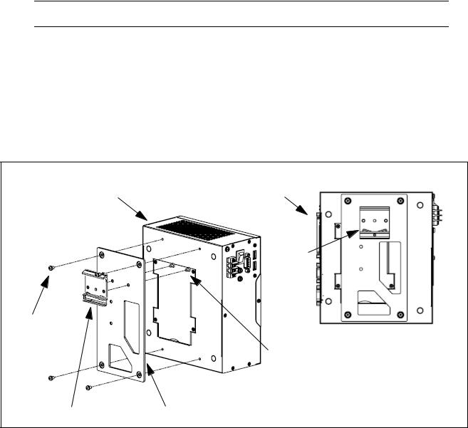
1.To fasten the mounting bracket to the bracket holding plate, insert the bracket mounting screws from the reverse side of the bracket holding plate.
Be sure to use the appropriate holes in the holding plate for the desired bracket orientation —horizontal or vertical. The part of the bracket that contains the butterfly clip should be on the bottom.
2.Fasten the bracket holding plate onto the bottom of the processor using the plate mounting screws.
3.Hook the bottom of the mounting bracket in the bottom flange of the DIN rail. The butterfly clips will offer some resistance.
4.While exerting slight upward force, clip the top of the mounting bracket over the top flange of the DIN rail.
5.Verify that the bracket is clipped securely to the rail.
IMPORTANT: See Mounting Warning on Page 1
Processor front |
Processor front |
Butterfly
Clip
Plate
Mounting
Screws Bottom View
(x4)
Bracket Mounting
Screws (x2)
Mounting Bracket |
Bracket Holding Plate |
|
DIN Rail Mounting (Fan Down)
Datalogic S.r.l. |
Page 6 |
M-Series Quick Reference Guide |
MX20 and MX40 Processor Power Supply Connection |
IMPORTANT: See Mounting Warning on Page 1
Processor front
Butterfly
Clip
Bottom View
Bracket Mounting
Plate Screws (x2)
Mounting
Screws
(x4)
Mounting Bracket
Bracket Holding Plate
DIN Rail Mounting (Front Up)
Warning: To avoid electrical shock, disconnect all power to the power supply before working on it.
Avertissement: Pour éviter le choc électrique, débranchez toute la puissance à l'alimentation d'énergie avant de travailler à lui.
MX20 and MX40 Processor Power Supply Connection
The MX20 and MX40 power inputs use standard spade terminals to connect the power supply. The ground terminal on the power input must be connected to the power supply’s grounded chassis/ enclosure. This connection is needed to insure electromagnetic compliance and proper operation.
The MX20 and MX40 processors require approximately 10A @ 10VDC; 3.5A @ 24VDC; and 3A @ 30VDC. Datalogic recommends using a 24 VDC power supply capable of providing 3.5A current. The M-Series processor runs most efficiently at this voltage which is commonly used in many manufacturing environments.
Power Connector |
1 |
3 2 |
1Connect Ground terminal to Power Supply Circuit Ground
2Connect - terminal to Power Supply Minus
3Connect + terminal to Power Supply 10 to 30VDC*
Page 7 |
Datalogic S.r.l. |
MX80 Processor Power Supply Connection |
M-Series Quick Reference Guide |
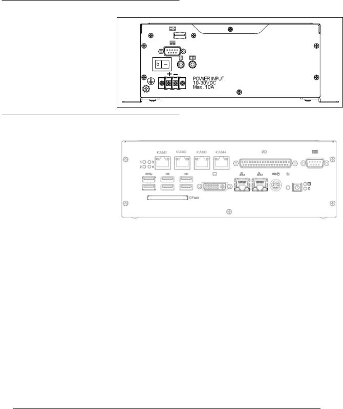
MX80 Processor Power Supply Connection
The MX80 power input uses a Datalogic-supplied connector. Wire the power supply cable to the connector, then plug it into the power connector on the rear of the processor. The ground terminal on the power input must be connected to the power supply’s grounded chassis/enclosure. This connection is needed to insure electromagnetic compliance and proper operation.
The MX80 processor requires approximately 5A @ 24VDC. Datalogic recommends using a 24 VDC power supply capable of providing 5A current. This voltage is commonly used in many manufacturing environments.
Power Connector |
V+ GND V- |
|
POWER INPUT 10-30VDC
Connect GND terminal to Power Supply Circuit Ground Connect V- terminal to Power Supply Minus
Connect V+ terminal to Power Supply 10 to 30VDC*
MX20 and MX40 Front Panel Connections
This is the MX20 and MX40 Processor’s front |
|
|
|
|
|
||
|
panel. |
|
|
|
|
|
|
|
|
|
|
|
J |
|
|
Symbol |
Function |
|
|
A |
|||
|
|
|
|
|
|
||
|
|
|
|
|
|
||
|
A |
Status Lights (see Page 10) |
|
|
I |
||
|
|
|
|
|
|||
|
B |
Reset Button (Resets the processor) |
|
|
E |
D C |
|
|
C |
Keyboard and Mouse |
|
|
|
|
|
|
|
|
|
H |
G |
B A |
|
|
D |
USB Ports 2.0 (2) |
|
||||
|
|
|
|
|
|
F |
|
|
E |
LAN Ethernet Ports (2) |
|
|
|
||
|
|
|
|
|
|
||
|
|
|
|
|
|
|
|
|
F |
Compact Flash Socket (See Note |
|
|
|
|
|
|
|
below) |
|
|
|
|
|
|
|
|
|
|
|
|
|
|
G |
VGA Connector |
|
|
|
|
|
|
|
|
|
|
|
|
|
|
H |
Serial Port 1 - See “MX20 and MX40 |
|
|
|
|
|
|
|
Serial Cable” on page 11 |
|
|
|
|
|
|
|
|
|
|
|
|
|
|
I |
M-Series Camera Connectors (CAM1- |
|
|
|
|
|
|
|
CAM4) MX20 has only 2 POE ports |
|
|
|
|
|
|
|
(CAM1-CAM2) |
|
|
|
|
|
|
|
Cable 606-0457-x |
|
|
|
|
|
|
|
|
|
|
|
|
|
|
J |
Digital I/O Connector - Cable 606- |
|
|
|
|
|
|
|
0675-xx with terminal block 661-0403 |
|
|
|
|
|
|
|
or terminal block 248-0110. Use cable |
|
|
|
|
|
|
|
431-0952-xx without terminal block. |
|
|
|
|
|
|
|
|
|
|
|
|
|
|
|
|
|
|
|
|
|
Note: If a Compact Flash card is present in the socket, it can be used for extended storage by the MX20 and MX40 processors. Do NOT insert or remove the card while the unit is powered on.
Datalogic S.r.l. |
Page 8 |
M-Series Quick Reference Guide |
MX20 and MX40 Rear Panel Connections |
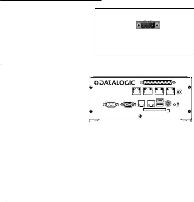
MX20 and MX40 Rear Panel Connections
This is the MX20 and MX40 Processors’ rear panel.
Symbol |
Function |
|
|
|
A |
|
|
|
A |
USB Port |
|
|
|
|
B |
Serial Port 2 |
B |
C |
Speaker and Microphone |
D |
|
|
C |
D |
Power Switch |
|
|
|
|
MX80 Front Panel Connections
These are the connections for the |
|
|
|
|
|
|||
|
MX80 Processor’s front panel. |
|
|
|
|
|
||
|
|
|
|
J |
K |
L |
||
Code |
Function |
|
||||||
|
|
|
|
|
|
|
|
|
|
|
|
|
|
|
|
|
|
A |
Status Lights (see Page 11) |
|
|
|
|
|
||
|
|
|
|
|
|
|
|
|
B |
Power Button |
|
I |
|
|
|
||
|
|
|
|
H |
|
|
|
|
C |
Reset Button (Resets the |
|
|
|
||||
|
|
|
|
|
||||
|
|
processor) |
|
F |
E |
D C B A |
||
|
|
|
|
|||||
D |
Keyboard and Mouse |
|||||||
|
G |
|
|
|
||||
E |
Gigabit Ethernet Ports (2) |
|
|
|
|
|
||
|
|
|
|
|
|
|
|
|
F |
DVI-I Video Connector (VGA |
|
|
|
|
|
||
|
|
|
|
|
||||
|
|
Capable) |
|
|
|
|
|
|
|
|
|
|
|
|
|
|
|
G |
CFast Compact Flash Socket |
|
|
|
|
|
||
|
|
(See Note below) |
|
|
|
|
|
|
|
|
|
|
|
|
|
|
|
H |
USB 3.0 Ports (2) |
|
|
|
|
|
||
|
|
|
|
|
|
|
|
|
I |
USB 2.0 Ports (4) |
|
|
|
|
|
||
|
|
|
|
|
|
|
|
|
J |
M-Series Camera Connec- |
|
|
|
|
|
||
|
|
tors (CAM1 - CAM4) |
|
|
|
|
|
|
|
|
Cable 606-0457-x |
|
|
|
|
|
|
|
|
|
|
|
|
|
|
|
K |
Digital I/O Connector - Cable |
|
|
|
|
|
||
|
|
606-0675-xx with terminal |
|
|
|
|
|
|
|
|
block 661-0403 or terminal |
|
|
|
|
|
|
|
|
block 248-0110. Use cable |
|
|
|
|
|
|
|
|
431-0952-xx without terminal |
|
|
|
|
|
|
|
|
block. |
|
|
|
|
|
|
|
|
|
|
|
|
|
|
|
L |
Serial Port 1 (Com 5) See |
|
|
|
|
|
||
|
|
“MX80 Serial Cable” on page |
|
|
|
|
|
|
|
|
12 |
|
|
|
|
|
|
|
|
|
|
|
|
|
|
|
|
|
|
|
|
|
|
|
|
Note: If a Compact Flash card is present in the socket, it can be used for extended storage by the processor. Do NOT insert or remove the card while the unit is powered on.
Page 9 |
Datalogic S.r.l. |
MX80 Rear Panel Connections M-Series Quick Reference Guide
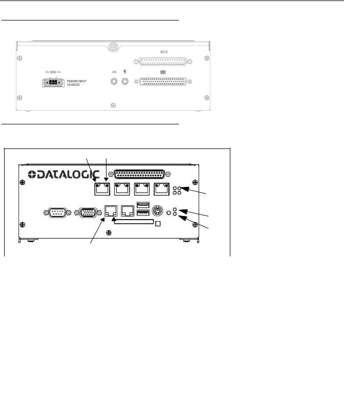
MX80 Rear Panel Connections
|
|
MX80 Processor’s rear panel connections |
||
|
|
|||
|
|
|
|
|
|
A |
|
Symbol |
Function |
|
|
|
|
|
|
|
|
|
|
|
|
|
A |
Do Not Use. (For future |
|
B |
|
|
expansion) |
|
|
|
|
|
|
|
B |
Serial Ports 2-4 (COM 2-4) |
|
|
|
|
||
|
|
|
|
|
C |
|
|
C |
Speaker and Microphone |
|
|
|
|
|
MX20 and MX40 Status Lights
These are the status lights on the front of the MX20 and MX40 Processors.
D E
|
|
|
|
|
A |
|
|
|
|
|
|
B |
|
|
|
|
|
|
C |
|
|
|
F |
|
|
|
|
|
|
G |
|
|
||
|
|
|
|
|
|
|
|
|
|
|
|
|
|
|
Symbol |
Name |
|
|
When lit indicates: |
|
|
|
|
|
|
|
|
|
|
|
|
|
|
|
|
A |
PoE: MX40 = 4 |
Power over Ethernet (PoE) is active (M1xx camera |
|||
|
|
MX20 = 2 |
|
|
only) |
|
|
|
|
|
|
|
|
|
B |
Power |
|
|
Power is On |
|
|
|
|
|
|
|
|
|
C |
HDD |
|
|
Blinking: Solid-state hard drive is active |
|
|
|
|
|
|
|
|
|
D |
PoE Activity/Link: |
On: Link is established |
|||
|
|
MX40 = 4; MX20 = 2 |
Blinking: Data is being transferred |
|||
|
|
|
|
|
|
|
|
E |
PoE Speed: |
|
|
Off: 10 Mbps |
|
|
|
MX40 = 4; MX20 = 2 |
Green: 100 Mbps |
|||
|
|
|
|
|
Orange: 1000 Mbps (Gigabit) |
|
|
|
|
|
|
|
|
|
F |
LAN 1 and 2 Speed |
Off: 10 Mbps |
|||
|
|
|
|
|
Green: 100 Mbps |
|
|
|
|
|
|
Orange: 1000 Mbps (Gigabit) |
|
|
|
|
|
|
|
|
|
G |
LAN 1 and 2 Activity/Link |
On: Link is established |
|||
|
|
|
|
|
Blinking: Data is being transferred |
|
|
|
|
|
|
|
|
Datalogic S.r.l. |
Page 10 |
Loading...