


 Loading...
DS2100N
Reference Manual

Datalogic Automation Srl Via S. Vitalino, 13
40012 - Lippo di Calderara di Reno Bologna - Italy
DS2100N Reference Manual
Ed.: 09/2008
ALL RIGHTS RESERVED
Datalogic reserves the right to make modifications and improvements without prior notification.
Datalogic shall not be liable for technical or editorial errors or omissions contained herein, nor for incidental or consequential damages resulting from the use of this material.
Product names mentioned herein are for identification purposes only and may be trademarks and or registered trademarks of their respective companies.
Datalogic is a registered trademark of Datalogic S.p.A. in many countries and the Datalogic logo is a trademark of Datalogic S.p.A.
© Datalogic Automation S.r.l. 2007 - 2008
15/09/08

CONTENTS
|
REFERENCES ............................................................................................................. |
v |
|
Conventions.................................................................................................................. |
v |
|
Reference Documentation ............................................................................................ |
v |
|
Services and Support ................................................................................................... |
v |
|
Patents.......................................................................................................................... |
v |
|
SAFETY AND COMPLIANCE NOTICES.................................................................... |
vi |
|
Laser Safety................................................................................................................. |
vi |
|
FCC Compliance ......................................................................................................... |
vii |
|
Power Supply............................................................................................................... |
vii |
|
CE Compliance............................................................................................................ |
vii |
|
Handling...................................................................................................................... |
viii |
|
GENERAL VIEW .......................................................................................................... |
x |
1 |
RAPID CONFIGURATION ........................................................................................... |
1 |
|
Step 1 – Connect the System ....................................................................................... |
1 |
|
Step 2 – Mounting and Positioning the System ............................................................ |
4 |
|
Step 3 – X-PRESS™ Configuration.............................................................................. |
5 |
|
Step 4 – Installing Genius™ Configuration Program .................................................... |
8 |
|
Step 5 – Test Mode .................................................................................................... |
13 |
|
Advanced Scanner Configuration ............................................................................... |
14 |
2 |
INTRODUCTION ........................................................................................................ |
15 |
2.1 |
Product Description .................................................................................................... |
15 |
2.1.1 |
Indicators .................................................................................................................... |
16 |
2.2 |
ID-NET™ .................................................................................................................... |
16 |
2.2.1 |
How To Setup/Configure the Scanner Network.......................................................... |
18 |
2.3 |
X-PRESS™ Human Machine Interface ...................................................................... |
19 |
2.3.1 |
Diagnostic Indication................................................................................................... |
19 |
2.3.2 |
X-PRESS™ Functions................................................................................................ |
20 |
2.4 |
Model Description ....................................................................................................... |
22 |
2.5 |
Accessories ................................................................................................................ |
23 |
3 |
INSTALLATION ......................................................................................................... |
24 |
3.1 |
Package Contents ...................................................................................................... |
24 |
3.2 |
Mechanical Installation ............................................................................................... |
25 |
3.2.1 |
Mounting DS2100N .................................................................................................... |
26 |
3.2.2 |
Mounting Scanner Accessories .................................................................................. |
27 |
3.3 |
Positioning .................................................................................................................. |
28 |
4 |
CBX ELECTRICAL CONNECTIONS......................................................................... |
30 |
4.1 |
Power Supply.............................................................................................................. |
31 |
4.2 |
Main Serial Interface................................................................................................... |
31 |
4.2.1 |
RS232 Interface.......................................................................................................... |
32 |
4.2.2 |
RS485 Full-Duplex Interface....................................................................................... |
33 |
4.2.3 |
RS485 Half-Duplex Interface ...................................................................................... |
34 |
4.3 |
ID-NET™ Interface ..................................................................................................... |
36 |
4.3.1 |
ID-NET™ Cables ........................................................................................................ |
36 |
4.3.2 |
ID-NET™ Response Time .......................................................................................... |
37 |
4.3.3 |
ID-NET™ Network Termination .................................................................................. |
41 |
4.4 |
Auxiliary RS232 Interface ........................................................................................... |
41 |
|
|
iii |

4.5 |
Inputs .......................................................................................................................... |
42 |
4.5.1 |
Code Verifier............................................................................................................... |
45 |
4.6 |
Outputs ....................................................................................................................... |
45 |
4.7 |
User Interface - Host................................................................................................... |
47 |
5 |
25-PIN CABLE ELECTRICAL CONNECTIONS........................................................ |
48 |
5.1 |
Power Supply.............................................................................................................. |
49 |
5.2 |
Main Serial Interface................................................................................................... |
49 |
5.2.1 |
RS232 Interface.......................................................................................................... |
50 |
5.2.2 |
RS485 Full-Duplex Interface....................................................................................... |
51 |
5.2.3 |
RS485 Half-Duplex Interface ...................................................................................... |
52 |
5.3 |
ID-NET™ Interface ..................................................................................................... |
54 |
5.3.1 |
ID-NET™ Cables ........................................................................................................ |
54 |
5.3.2 |
ID-NET™ Response Time .......................................................................................... |
55 |
5.3.3 |
ID-NET™ Network Termination .................................................................................. |
59 |
5.4 |
Auxiliary RS232 Interface ........................................................................................... |
59 |
5.5 |
Inputs .......................................................................................................................... |
60 |
5.5.1 |
Code Verifier............................................................................................................... |
63 |
5.6 |
Outputs ....................................................................................................................... |
63 |
5.7 |
User Interface - Host................................................................................................... |
64 |
6 |
TYPICAL LAYOUTS .................................................................................................. |
65 |
6.1 |
Point-to-Point .............................................................................................................. |
65 |
6.2 |
Pass-Through ............................................................................................................. |
67 |
6.3 |
ID-NET™ .................................................................................................................... |
69 |
6.4 |
RS232 Master/Slave................................................................................................... |
72 |
6.5 |
Multiplexer Layout....................................................................................................... |
73 |
7 |
READING FEATURES............................................................................................... |
74 |
7.1 |
Advanced Code Builder (ACB) ................................................................................... |
74 |
7.1.1 |
Important ACB Reading Conditions............................................................................ |
75 |
7.1.2 |
Tilt Angle Improvement with ACB ............................................................................... |
75 |
7.2 |
Linear Code Reading.................................................................................................. |
75 |
7.2.1 |
Step-Ladder Mode ...................................................................................................... |
76 |
7.2.2 |
Picket-Fence Mode..................................................................................................... |
77 |
7.3 |
Performance ............................................................................................................... |
78 |
7.3.1 |
Raster ......................................................................................................................... |
78 |
7.4 |
Reading Diagrams ...................................................................................................... |
79 |
8 |
MAINTENANCE ......................................................................................................... |
85 |
8.1 |
Cleaning...................................................................................................................... |
85 |
9 |
TROUBLESHOOTING ............................................................................................... |
86 |
9.1 |
General Guidelines ..................................................................................................... |
86 |
10 |
TECHNICAL FEATURES........................................................................................... |
89 |
|
GLOSSARY................................................................................................................ |
91 |
|
INDEX......................................................................................................................... |
94 |
iv

REFERENCES
CONVENTIONS
This manual uses the following conventions:
“User” or “Operator” refers to anyone using a DS2100N. “Device” refers to the DS2100N.
“You” refers to the System Administrator or Technical Support person using this manual to install, mount, operate, maintain or troubleshoot a DS2100N.
REFERENCE DOCUMENTATION
The documentation related to the DS2100N management is listed below:
•
•
•
•
•
CBX100 Installation Manual
CBX500 Installation Manual
CBX Accessory Manuals
OM2000N Installation Manual
Genius™ Help On Line
SERVICES AND SUPPORT
Datalogic provides several services as well as technical support through its website. Log on to www.automation.datalogic.com and click on the links indicated for further information including:
•PRODUCTS
Search through the links to arrive at your product page where you can download specific
Manuals and Software & Utilities including:
-Genius™ a utility program, which allows device configuration using a PC. It provides RS232 interface configuration.
•SERVICES & SUPPORT
-Datalogic Services - Warranty Extensions and Maintenance Agreements
-Authorised Repair Centres
•CONTACT US
E-mail form and listing of Datalogic Subsidiaries
PATENTS
This product is covered by one or more of the following patents:
U.S. patent 5,992,740
European patent 789,315 B1
v
SAFETY AND COMPLIANCE NOTICES
LASER SAFETY
The following information is provided to comply with the rules imposed by international authorities and refers to the correct use of the DS2100N scanner.
Standard Regulations
This scanner utilizes a low-power laser diode. Although staring directly at the laser beam momentarily causes no known biological damage, avoid staring at the beam as one would with any very strong light source, such as the sun. Avoid that the laser beam hits the eye of an observer, even through reflective surfaces such as mirrors, etc.
This product conforms to the applicable requirements of IEC 60825-1 and complies with 21 CFR 1040.10 except for deviations pursuant to Laser Notice N° 50, date June 24, 2007. The scanner is classified as a Class 2 laser product according to IEC 60825-1 regulations.
There is a safety device, which allows the laser to be switched on only if the motor is rotating above the threshold for its correct scanning speed.
The laser beam can be switched off through a software command (see also the Genius™ Help On Line).
WARNING
Use of controls or adjustments or performance of procedures other than those specified herein may result in exposure to hazardous visible laser light.
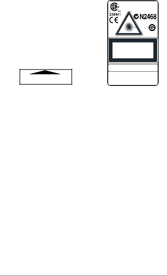
The laser light is visible to the human eye and is emitted from the window on the front of the scanner (Figure A, 7).
Warning labels indicating exposure to laser light and the device classification are applied onto the body of the scanner (Figure A, 1).
vi
Disconnect the power supply when opening the device during maintenance or installation to avoid exposure to hazardous laser light.
The laser diode used in this device is classified as a class 3B laser product according to EN 60825-1 regulations and as a Class IIIb laser product according to CDRH regulations.
Any violation of the optic parts in particular can cause radiation up to the maximum level of the laser diode (35 mW at 630 to 680 nm).
AVOID EXPOSURE LASER LIGHT
IS EMITTED FROM THIS APERTURE
Complies with 21 CFR 1040.10 except for deviations pursuant to Laser Notice N°50, date June 24, 2007
LASER LIGHT
DO NOT STARE INTO BEAM
CLASS 2 LASER PRODUCT
MAX. OUTPUT RADIATION 1 mW
EMITTED WAVE LENGTH 630~680 nm
TO IEC 60825-1:1993+A1:1997+A2:2001
CAUTION-CLASS 3B LASER LIGHT
WHEN OPEN AVOID EXPOSURE TO BEAM
Pat. US5992740, EP0789315B1
DATALOGIC AUTOMATION S.r.l.
Via S. Vitalino, 13 – 40012 Calderara di Reno MADE IN ITALY-www.datalogic.com
Warning and Device Class Labels
FCC COMPLIANCE
Modifications or changes to this equipment without the expressed written approval of Datalogic could void the authority to use the equipment.
This device complies with PART 15 of the FCC Rules. Operation is subject to the following two conditions: (1) This device may not cause harmful interference, and (2) this device must accept any interference received, including interference which may cause undesired operation.
This equipment has been tested and found to comply with the limits for a Class A digital device, pursuant to part 15 of the FCC Rules. These limits are designed to provide reasonable protection against harmful interference when the equipment is operated in a commercial environment. This equipment generates, uses, and can radiate radio frequency energy and, if not installed and used in accordance with the instruction manual, may cause harmful interference to radio communications. Operation of this equipment in a residential area is likely to cause harmful interference in which case the user will be required to correct the interference at his own expense.
POWER SUPPLY
This product is intended to be installed by Qualified Personnel only.
This accessory device is intended to be supplied by a UL Listed or CSA Certified Power Unit with «Class 2» or LPS power source, which supplies power directly to the scanner via the 25pin connector.
CE COMPLIANCE
Warning:
This is a Class A product. In a domestic environment this product may cause radio interference in which case the user may be required to take adequate measures.
vii

HANDLING
The DS2100N is designed to be used in an industrial environment and is built to withstand vibration and shock when correctly installed, however it is also a precision product and therefore before and during installation it must be handled correctly to avoid damage.
•avoid that the scanners hit one another causing damage. They should be handled separately.
•avoid that the scanners are dropped (exceeding shock limits).
•do not fine tune the positioning by striking the scanner or bracket.
viii

•do not weld the scanner into position which can cause electrostatic, heat or output window damage.
•do not spray paint near the scanner which can cause output window damage.
ix
GENERAL VIEW
DS2100N
4 |
5 |
6 |
|
|
2
3
7
|
11 |
|
10 |
|
1 |
|
|
9 |
8 |
|
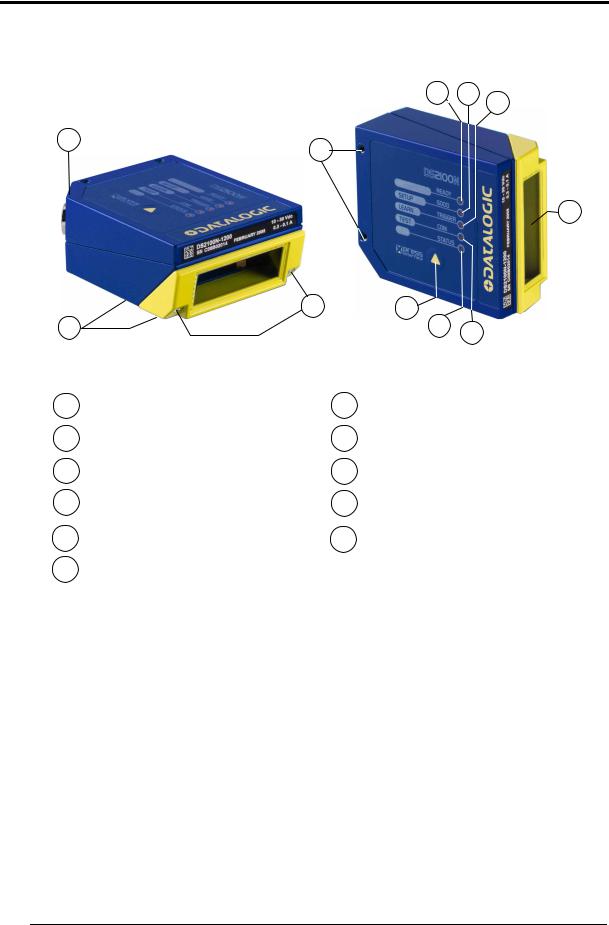
Figure A |
|
|
|
1 |
Warning and Device Class Labels |
7 |
Laser Beam Output Window |
|
2 |
"POWER ON" LED |
8 |
"COM" LED |
|
3 |
Mounting Holes |
9 |
"STATUS" LED |
|
4 |
"READY" LED |
10 |
Push Button |
|
5 |
"GOOD" LED |
11 |
Accessory Mounting Holes |
|
6 |
"TRIGGER" LED |
|
|
|
x
RAPID CONFIGURATION
1
1 RAPID CONFIGURATION
This chapter illustrates a Stand Alone application. For other types of installations, such as ID-NET™, Fieldbus, Pass-Through, Multiplexer Layout, etc., refer to chapters 4, 5 and 6. For complete scanner configuration using the
NOTE Genius™ configuration program, refer to the Context-Sensitive Help On-Line.
STEP 1 – CONNECT THE SYSTEM
To connect the system in a Stand Alone configuration, you need the hardware indicated in Figure 1.
In this layout the data is transmitted to the Host on the main serial interface.
In Local Echo communication mode, data is transmitted on the RS232 auxiliary interface independently from the main interface selection.
When On-Line Operating mode is used, the scanner is activated by an External Trigger (photoelectric sensor) when the object enters its reading zone.
PG 6000
MAIN
DS2100N |
CBX100/500 |
Host
|
|
|
|
|
|
|
|
|
|
|
|
* Presence Sensor |
|
|
|
|
|
|
|
|
|
|
|
|
|
|
|
|
P.S.* |
|
I/O, AUX |
|||||||
|
|
|
|
(for On-Line mode) |
||||||||
Figure 1 – DS2100N in Stand Alone Layout
1

DS2100N REFERENCE MANUAL
1
CBX100/500 Pinout for DS2100N
The table below gives the pinout of the CBX100/500 terminal block connectors. Use this pinout when the DS2100N reader is connected by means of the CBX100/500:
CBX100/500 Terminal Block Connectors
|
Input Power |
|
|
|
|
Outputs |
|
Vdc |
Power Supply Input Voltage + |
|
+V |
Power Source - Outputs |
|||
GND |
Power Supply Input Voltage - |
|
-V |
Power Reference - Outputs |
|||
Earth |
Protection Earth Ground |
|
O1+ |
Output 1 + |
|||
|
|
|
|
O1- |
Output 1 - |
||
|
Inputs |
|
O2+ |
Output 2 + |
|||
+V |
Power Source – External Trigger |
O2- |
Output 2 - |
||||
I1A |
External Trigger A (polarity insensitive) |
|
Auxiliary Interface |
||||
I1B |
External Trigger B (polarity insensitive) |
TX |
Auxiliary Interface TX |
||||
-V |
Power Reference – External Trigger |
RX |
Auxiliary Interface RX |
||||
+V |
Power Source – Inputs |
|
SGND |
Auxiliary Interface Reference |
|||
I2A |
Input 2 A (polarity insensitive) |
|
|
|
ID-NET™ |
||
I2B |
Input 2 B (polarity insensitive) |
|
REF |
Network Reference |
|||
-V |
Power Reference – Inputs |
|
ID+ |
ID-NET™ network + |
|||
|
Shield |
|
ID- |
ID-NET™ network - |
|||
Shield |
Network Cable Shield |
|
|
|
|
|
|
|
|
Main Interface |
|
|
|
||
|
RS232 |
|
RS485 Full-Duplex |
|
RS485 Half-Duplex |
||
|
TX |
|
|
TX+ |
|
|
RTX+ |
|
RTS |
|
|
TX- |
|
|
RTX- |
|
RX |
|
|
*RX+ |
|
|
|
|
CTS |
|
|
*RX- |
|
|
|
|
SGND |
|
|
SGND |
|
|
SGND |
* Do not leave floating, see par. 4.2.2 for connection details.
|
Do not connect GND, SGND and REF to different (external) ground |
|
references. GND, SGND and REF are internally connected through filtering |
CAUTION |
circuitry which can be permanently damaged if subjected to voltage drops |
over 0.8 Vdc. |
2

RAPID CONFIGURATION
1
25-pin Connector Pinout for DS2100N
The table below gives the pinout of the 25-pin power supply and input/output signals. Use connected by means of the 25-pin connector:
male D-sub connector for connection to the this pinout when the DS2100N reader is
|
1 |
|
|
13 |
|
|
|
14 |
|
25 |
|
||
|
Figure 2 - 25-pin Male D-sub Connector |
|
||||
|
25-pin D-sub male connector pinout |
|
||||
Pin |
Name |
Function |
|
|
|
|
13, 9 |
Vdc |
Power supply input voltage + |
|
|||
25, 7 |
GND |
Power supply input voltage - |
|
|||
1 |
CHASSIS |
Cable shield connected to chassis |
|
|||
18 |
I1A |
External Trigger A (polarity insensitive) |
|
|||
19 |
I1B |
External Trigger B (polarity insensitive) |
|
|||
6 |
I2A |
Input 2 A (polarity insensitive) |
|
|||
10 |
I2B |
Input 2 B (polarity insensitive) |
|
|||
8 |
O1+ |
Output 1 + |
|
|
|
|
22 |
O1- |
Output 1 - |
|
|
|
|
11 |
O2+ |
Output 2 + |
|
|
|
|
12 |
O2- |
Output 2 - |
|
|
|
|
20 |
RX |
Auxiliary RS232 RX |
|
|
||
21 |
TX |
Auxiliary RS232 TX |
|
|
||
23 |
ID+ |
ID-NET™ network + |
|
|
||
24 |
ID- |
ID-NET™ network - |
|
|
||
14, 15, 16, 17 |
NC |
Not Connected |
|
|
|
|
Pin |
Name |
RS232 |
|
RS485 |
RS485 |
|
Full-Duplex |
Half-Duplex |
|||||
|
|
|
||||
2 |
|
TX |
|
TX+ |
RTX+ |
|
3 |
MAIN INTERFACE |
RX |
|
*RX+ |
|
|
4 |
(SW SELECTABLE) |
RTS |
|
TX- |
RTX- |
|
5 |
|
CTS |
|
*RX- |
|
|
* Do not leave floating, see par. 5.2.2 for connection details.
3

DS2100N REFERENCE MANUAL
1
STEP 2 – MOUNTING AND POSITIONING THE SYSTEM
1.To mount the DS2100N, use the mounting bracket to obtain the most suitable position for the reader as shown in the figures below.

 Skew
Skew
Tilt |
Pitch |
Skew
Figure 3 - Positioning with Mounting Bracket
2.When mounting the DS2100N take into consideration these three ideal label position angles:
Skew 10° to 30°, Tilt 0° and Pitch 0°.
T
S


Assure at least 10° |
Minimize |
|
|
|
|
Figure 4 –Skew and Tilt Angles
P
Minimize
Figure 5 – Pitch Angle
3.Refer to the Reading Diagrams in par. 7.4 to decide the distance your scanner should be positioned at.
4

RAPID CONFIGURATION
1
STEP 3 – X-PRESS™ CONFIGURATION
X-PRESS™ is the intuitive Human Machine Interface designed to improve ease of installation and maintenance.
Status and diagnostic information are clearly presented by means of the five colored LEDs, whereas the single push button gives immediate access to the following relevant functions:
•AutoSetup to self-optimize and auto-configure reading performance in demanding applications
•AutoLearn to self-detect and auto-configure for reading unknown barcodes (by type and length)
•Test Mode with bar-graph visualization to check static reading performance
|
If using the OM2000N accessory, when entering the X-PRESS™ interface, the |
|
Oscillating Mirror remains in the default fixed position (-15°) in order to make |
NOTE |
barcode reading easier while performing the X-PRESS™ functions. |
|
The colors and meaning of the five LEDs are illustrated in the following table:
READY (green) |
This LED indicates the device is ready to operate. |
|
|
GOOD (green) |
This LED confirms successful reading. |
|
|
TRIGGER (yellow) |
This LED indicates the status of the reading phase. |
|
|
COM (yellow) |
This LED indicates active communication on main serial port. * |
|
|
STATUS (red) |
This LED indicates a NO READ result. |
|
|
* When connected to a Fieldbus network through the CBX500, the COM LED is always active, even in the absence of data transmission, because of polling activity on the Fieldbus network.
During the reader startup (reset or restart phase), all the LEDs blink for one second.
On the back of the reader near the cable, the “POWER ON” LED indicates the laser scanner is correctly powered.
5

DS2100N REFERENCE MANUAL
1
Auto Learn
If you are configuring your scanner using X-PRESS™, you must start with the Auto Learn procedure.
1.Enter the Auto Learn function by holding the X-PRESS™ push button pressed until the LEARN LED is on.
2.Release the button to enter the Auto Learn function.
Once entered, the reader starts a procedure to automatically detect and recognize barcodes (by type and length), which are presented to it (*). The laser turns on and the LEARN LED blinks to indicate the ongoing process.
|
READY |
green |
|
|
|
SETUP |
GOOD |
green |
|
||
LEARN |
TRIGGER |
yellow |
|
||
TEST |
COM |
yellow |
|
||
|
STATUS |
red |
|
|
Figure 6 – X-PRESS™ Interface: Auto Learn Function
The procedure is as follows:
A)place the desired barcode on the scanline.
B)wait until the LEARN LED stays steady on (indicating the reader has detected the barcode).
C)repeat, if needed, the above two steps to program up to 10 different barcodes (the LEARN LED returns to the blinking state for the next code). If more than one barcode is detected in the scan line, the Multi Label mode is enabled (refer to the “2K/4K Family Software Configuration Parameter Guide” Help file).
3.Exit the process by pressing the X-PRESS™ push button once. The scanner will restart at the end of the process, and then the detected barcodes are automatically configured in scanner memory.
If the barcode cannot be read because of low contrast or excessive ambient light, you can perform the AutoSetup function to optimize the optical parameters. Then you can perform AutoLearn to recognize the barcode
NOTE symbology.
|
On exit from Autolearn, the following parameters are forced: Code |
|
Combination = Single Label, Reading Mode = Linear. If necessary, these |
NOTE |
parameters can be changed through Genius™. |
|
* In case of Programming Barcodes (refer to the “ID-NET™: Programming Barcodes And Setup Procedure” document in the product CD).
6

RAPID CONFIGURATION
1
Auto Setup (Optional)
At the end of the Auto Learn procedure, you have the possibility to follow the Auto Setup procedure to set up the reading parameters.
1.Enter the Auto Setup function by holding the X-PRESS™ push button pressed until the SETUP LED is on.
2.Release the button to enter the Auto Setup function.
3.Once entered, if a barcode label is positioned in front of the scanline, the scanner automatically performs the optimal setup of the reading parameters for that specific barcode.
|
READY |
green |
|
|
|
SETUP |
GOOD |
green |
|
||
LEARN |
TRIGGER |
yellow |
|
||
TEST |
COM |
yellow |
|
||
|
STATUS |
red |
|
|
Figure 7 – X-PRESS™ Interface: Auto Setup Function
The procedure is as follows:
A)place the desired barcode on the scanline.
B)enter the AutoSetup function (the laser turns on and the SETUP LED blinks to indicate the ongoing process)
C)wait until the SETUP LED stays steady on (indicating the reader has detected the barcode)
This procedure ends either when the barcode is successfully decoded or after a timeout of about 7 (seven) seconds.
The scanner will restart at the end of the process, and then the optimized reading parameters for that barcode are automatically configured in scanner memory.
If your application has been configured using X-PRESS™, go to STEP 5.
NOTE
Reset Scanner to Factory Default (Optional)
If it ever becomes necessary to reset the scanner to the factory default values, you can perform this procedure by holding the X-PRESS™ push button pressed while powering up the scanner. At the end of the procedure (about 5-6 seconds), the Configuration and Environmental parameters are reset, and all LEDs blink simultaneously 3 times. If connected through a CBX500 with display module, the message "Default Set" is shown on the display.
7

DS2100N REFERENCE MANUAL
1
STEP 4 – INSTALLING GENIUS™ CONFIGURATION PROGRAM
Genius™ is a Datalogic scanner configuration tool providing several important advantages:
•Wizard approach for new users;
•Multi-language version;
•Defined configuration directly stored in the reader;
•Communication protocol independent from the physical interface allowing to consider the reader as a remote object to be configured and monitored.
To install Genius™, turn on the PC that will be used for the configuration, running Windows 98, 2000/NT, XP or Vista, then insert the Genius™ CD-ROM, wait for the CD to autorun and follow the installation procedure.
This configuration procedure assumes scanner connection to a CBX100/500. Genius™, running on a laptop computer, is connected to the scanner auxiliary port through the CBX100/500 9-pin connector. To communicate with the scanner, Genius™ performs an auto baudrate detection starting from its default parameters which are 115200, 8, N, 1. These parameters can also be set in the Genius™ Tools>Options>Communications window.
Wizard for Quick Reader Setup
After installing the Genius™ software program the following window appears asking the user to choose the desired configuration level.
Figure 8 - Genius™ Wizard Opening Window
The Wizard option is advised for rapid configuration or new users, since it shows a step-by- step scanner configuration.
8

RAPID CONFIGURATION
1
1. Select the Create a new configuration button.
You will be guided through the configuration being asked to define the following parameters:
a.Barcode selection and definition
9
DS2100N REFERENCE MANUAL
1
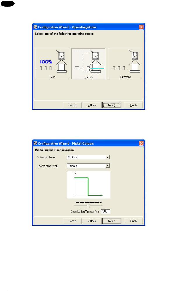
b.Operating mode selection and definition
c.Digital Outputs configuration
10

RAPID CONFIGURATION
1
d.Hardware interface selection
e.Output data format configuration
The On Line operating Mode requires the reader to be connected to an External Trigger/Presence Sensor using I1A and I1B inputs.
The Automatic operating mode does not require connection to an external Presence Sensor. When working in this mode the reader is continuously scanning, while the reading phase is activated each time a barcode enters the reader reading zone. The reader stops reading after an N number of scans without a code. Barcode characters are transmitted on the serial interface. In case of a failed reading phase no message is sent to the host computer.
11
DS2100N REFERENCE MANUAL
1
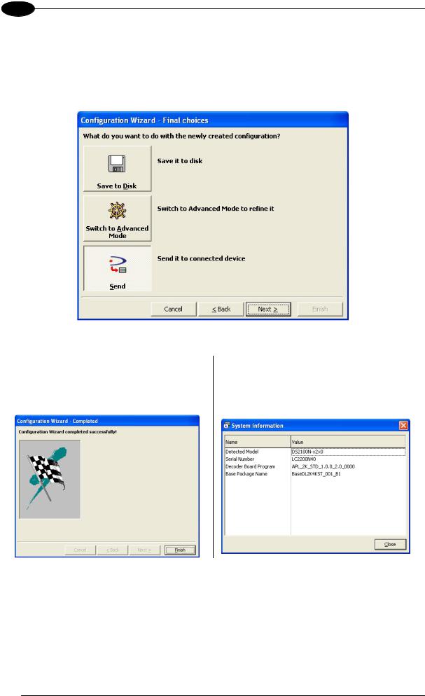
2.After defining the parameter values the following window appears allowing to complete the reader configuration as follows:
•Saving the configuration to disk;
•Switching to Advanced mode;
•Sending the configuration to the scanner.
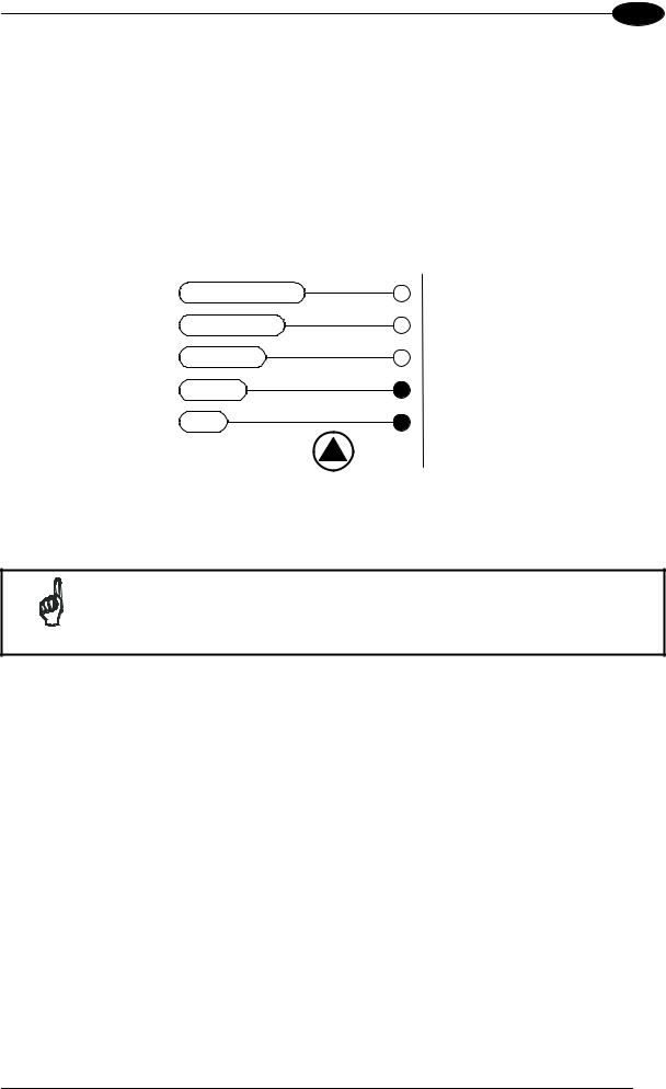
3.After sending the configuration to the scanner you have completed the configuration process.
4.By clicking Finish, the System Information window will be displayed with specific information concerning the scanner.
12
RAPID CONFIGURATION
1
STEP 5 – TEST MODE
Use a code suitable to your application to test the system. Alternatively, you can use the Datalogic Test Chart (Code 39, Code Interleaved 2/5).
1.Enter the Test mode function by holding the X-PRESS™ push button pressed until the TEST LED is on.
2.Release the button to enter the Test mode function.
Once entered, the Bar-Graph on the five LEDs is activated and if the scanner starts reading barcodes the Bar-Graph shows the Good Read Rate. In case of no read condition, only the STATUS LED is on and blinks.
|
READY |
green |
|
|
|
SETUP |
GOOD |
green |
|
||
LEARN |
TRIGGER |
yellow |
|
||
TEST |
COM |
yellow |
|
||
|
STATUS |
red |
|
|
Figure 9 – X-PRESS™ Interface: Test Mode Function
3. To exit the Test Mode, press the X-PRESS™ push button once.
By default, the Test Mode exits automatically after two minutes.
NOTE
13
DS2100N REFERENCE MANUAL
1
ADVANCED SCANNER CONFIGURATION
For further details on advanced product configuration, refer to the complete Reference Manual on the installation CD-ROM or downloadable from the web site through this link: www.automation.datalogic.com/ds2100n.
The following are alternative or advanced scanner configuration methods:
Host Mode Programming
The scanner can also be configured from a host computer using the Host Mode programming procedure, by commands via the serial interface. See the Host Mode Programming file on the CD-ROM.
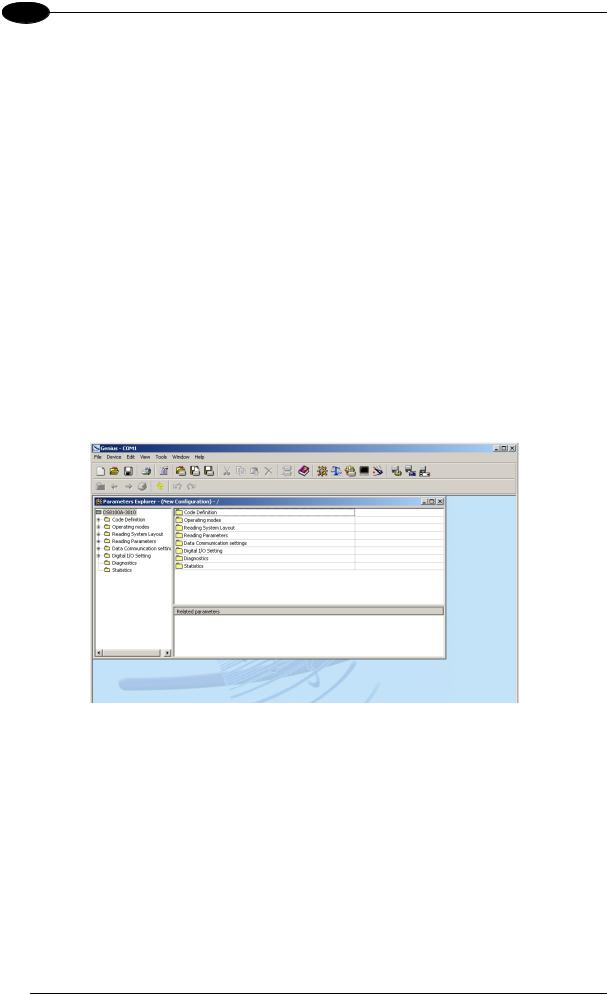
Advanced Genius™ Configuration
The ADVANCED selection available when starting the Genius™ program is addressed to expert users being able to complete a detailed scanner configuration. By choosing this option it is possible either to start a new scanner configuration or to open and modify an old one. The desired parameters can be defined in the following window, similar to the MS Explorer:
Figure 10 - Genius™ Parameter Explorer Window
Alternative Layouts
•The ID-NET™ is a built-in high-speed interface dedicated for high-speed scanner interconnection. ID-NET™ is in addition to the Main and Auxiliary serial interfaces.
If you need to install an ID-NET™ network refer to the DS2100N Reference Manual.
The scanner can also be configured by reading programming barcodes. See the IDNET™ Setup Procedure Using Programming Barcodes printable from the CD-ROM.
•If you need to install a Pass-Through network refer to the DS2100N Reference Manual.
•If you need to install a Multiplexer network refer to the DS2100N Reference Manual.
•If you need to install an RS232 Master/Slave (for backward compatibility) refer to the DS2100N Reference Manual.
14

INTRODUCTION
2
2 INTRODUCTION
2.1 PRODUCT DESCRIPTION
The DS2100N laser scanner satisfies the most advanced needs of a wide range of users. It has been developed focusing on the realistic requirements of its target market. The outstanding result is an extremely compact, cost-effective and easy to use industrial scanner.
Standard Application |
A standard application program is factory-loaded onto the |
Program |
DS2100N. This program controls barcode reading, serial port |
|
interfacing, data formatting and many other operating and control |
|
parameters. |
|
It is completely configurable from a host computer through the |
|
Genius™ utility program provided on CD with the scanner, or via |
|
the serial interface (Genius™ based Host Mode Programming). |
Custom Application |
If the Standard Application Program does not meet your |
Programs |
requirements, please contact your local Datalogic distributor. |
Some of the main features of DS2100N are listed below:
•ACB (Advanced Code Builder)
•small dimensions and light weight
•software programmable scanning speed on all models
•linear and raster version
•completely configurable via serial interface (Genius™)
•3 serial communication interfaces (Main, Auxiliary, ID-NET™)
•supply voltage from 10 to 30 Vdc
•reads all popular codes
•test mode to verify the reading features and exact positioning of the scanner without the need for external tools
•programmable in 4 different operating modes to suit the most various barcode reading system requirements
•code verifier
•low power consumption
The DS2100N uses a solid-state laser diode as a light source; the light emitted has a wavelength between 630 and 680 nm. Refer to the section “Safety Precautions” at the beginning of this manual for information on laser safety.
The protection class of the enclosure is IP65, the reader is therefore suitable for industrial environments where high protection against harsh external conditions is required.
15
DS2100N REFERENCE MANUAL
2
2.1.1Indicators
The five LEDs on the side of the scanner (Figure A) indicate the following:
READY |
(green) |
This LED indicates the device is ready to operate. |
GOOD |
(green) |
This LED confirms successful reading. |
TRIGGER |
(yellow) |
This LED indicates the status of the reading phase. * |
COM |
(yellow) |
This LED indicates active communication on main serial port. ** |
STATUS |
(red) |
This LED indicates a NO READ result. |
*In On-Line mode the TRIGGER LED corresponds to the active reading phase signaled by the Presence Sensor. In Automatic and Continuous modes the TRIGGER LED is always on indicating that the reader is ready to read a code.
**When connected to a Fieldbus network through the CBX500, the COM LED is always active, even in the absence of data transmission, because of polling activity on the Fieldbus network.
During the reader startup (reset or restart phase), all the LEDs blink for one second.
On the back of the reader near the cable, the “POWER ON” LED indicates the laser scanner is correctly powered.
2.2 ID-NET™
The ID-NET™ is a built-in high-speed interface dedicated for highspeed scanner interconnection. The ID-NET™ is in addition to the Main and Auxiliary serial interfaces.
The following network configurations are available:
ID-NET™ M/S Synchronized: Single station – multiple scanners
CBX100 |
CBX100 |
CBX100 |
ID-NET™ interface allows local connection of multiple scanners reading different sides of the same target. All scanners share a single presence sensor and activate/deactivate simultaneously.
At the end of each reading phase a single data message is transmitted to the host.
Thanks to ID-NET™, data communication among scanners is highly efficient so that an immediate result will be available.
16
INTRODUCTION
2
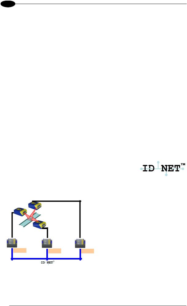
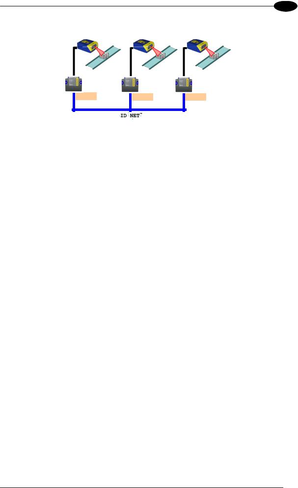
ID-NET™ M/S Multidata: Multiple stations – single scanner
CBX100 |
CBX100 |
CBX100 |
ID-NET™ interface allows connection of scanners reading objects placed on independent conveyors. All scanners are typically located far away from each other and they use a dedicated presence sensor.
At the end of each reading phase, each scanner transmits its own data message to the host. Thanks to ID-NET™, data collection among readers is accomplished at a high speed without the need of external multiplexing device. This leads to an overall cost reduction and to a simple system wiring.
17

DS2100N REFERENCE MANUAL
2
2.2.1How To Setup/Configure the Scanner Network
A complete ID-NET™ scanner network can be rapidly setup, as follows:
Mounting & Connection
1.Mechanically mount/install all the readers (refer to par. 3.2 and 3.3).
2.Wire ID-NET™ (refer to par. 4.3 or 5.3).
3.Connect the planned Master scanner to a PC by means of the Genius™ configuration software.
4.Power up the entire system.
Configuration
1.Launch Genius™.
2.From the Genius™ Device Menu select “Local Device Network Settings” and program the Role of the Master scanner (Synchronized or Multidata).
This procedure requires the Network Baud Rate be the same for all Slaves and Master, (500 kbs is the default value). It can be changed after network setup using Genius™ through the Master scanner. See also the alternative procedure in the note below.
3.At the prompt to "Send updated Network configuration to the Local Device" (Master) choose "Yes".
4.Then run the NET-AUTOSET procedure from the Icon in the Devices Area. Genius™ sets all slave scanners according to the Master Role (Synchronized or Multidata), and assigns each a random address. If necessary, this address can be changed through the Network Wizard.
5.Configure the System parameters via Genius™.
6.If using the CBX connection box equipped with a BM100 Backup module, perform System Backup at the Master.
The scanner network is ready.
If necessary, the ID-NET™ baudrate can be set individually on each Slave scanner to match the Master. Connect each Slave to Genius™ and set the Reading System Layout > Network Baudrate parameter. Then follow the
NOTE procedure above.
An alternative method of programming scanner address and role assignment can be accomplished by using the “Connectivity Programming Barcodes” (refer to the “ID-NET™ Setup Procedure Using Programming Barcodes”
NOTE document on the product CD).
18

INTRODUCTION
2
2.3 X-PRESS™ HUMAN MACHINE INTERFACE
X-PRESS™ is the intuitive Human Machine Interface designed with the precise goal of improving ease of installation and maintenance.
Status and diagnostic information are clearly presented by means of five-colored LEDs, whereas the single multi-function key gives immediate access to relevant functions:
•
•
•
Autosetup to self-optimize reading performance in demanding applications
Autolearn to self-detect unknown barcodes
Test Mode with bar-graph visualization to check static reading performance
X-PRESS™ is the common interface adopted in all new products: “You learn one, you can use them all”.
The colors and meaning of the five LEDs when in the one of the operating modes (On-Line, Automatic or Continuous) are illustrated in par 2.1.1.
The X-PRESS™ functions do not work if the motor or laser are turned off, see chp. 9 for details.
NOTE
2.3.1Diagnostic Indication
The “STATUS” and “READY” LEDs blink simultaneously to signal the presence of a failure. Diagnostic message transmission on interfaces can be enabled to provide details about specific failure conditions.
At the same time one or more LEDs light up according to the following scheme:
|
READY |
LED |
STATUS |
|
SETUP |
GOOD |
READY |
BLINK |
|
|
|
ON to indicate any Failure different than |
||
|
TRIGGER |
GOOD |
||
LEARN |
Motor or Laser failures. |
|||
|
|
|||
TEST |
COM |
TRIGGER |
ON to indicate a Motor Failure. |
|
|
||||
|
|
|
||
|
STATUS |
COM |
ON to indicate a Laser Failure. |
|
|
|
STATUS |
BLINK |
19
DS2100N REFERENCE MANUAL
2
2.3.2X-PRESS™ Functions
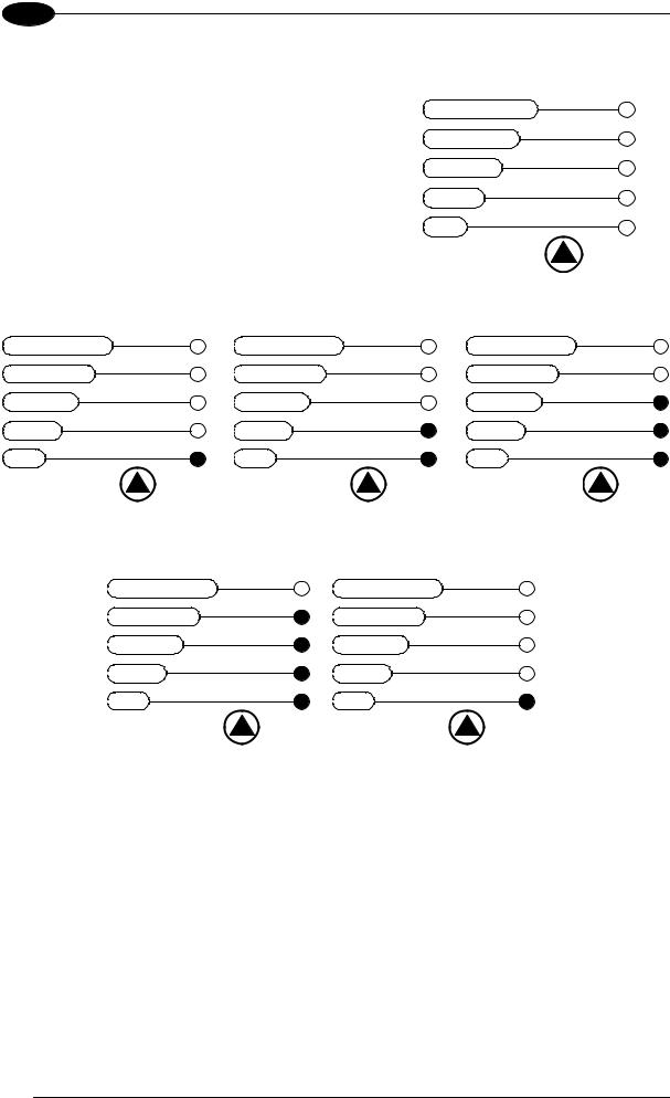
Quick access to the following functions is provided by an easy procedure using the push button:
1 – Press the button (the STATUS LED will give a visual feedback).
2 – Hold the button until the specific function LED is on (TEST, LEARN or SETUP).
3 – Release the button to enter the specific function.
READY
SETUP GOOD LEARN TRIGGER TEST COM
STATUS
Once button is pressed, the cycle of LEDs activation is as follows:
|
READY |
|
READY |
|
READY |
SETUP |
GOOD |
SETUP |
GOOD |
SETUP |
GOOD |
|
|
|
|||
LEARN |
TRIGGER |
LEARN |
TRIGGER |
LEARN |
TRIGGER |
|
|
|
|||
TEST |
COM |
TEST |
COM |
TEST |
COM |
|
|
|
|||
|
STATUS |
|
STATUS |
|
STATUS |
Release button to |
|
Release button to |
|
Release button to |
Exit |
|
enter Test Mode |
|
enter AutoLearn |
|
|
READY |
|
READY |
|
SETUP |
GOOD |
SETUP |
GOOD |
|
|
|
||
|
LEARN |
TRIGGER |
LEARN |
TRIGGER |
|
|
|
||
|
TEST |
COM |
TEST |
COM |
|
|
|
||
|
|
STATUS |
|
STATUS |
|
Release button to |
|
Release button to |
(cycle) |
|
|
|
||
|
enter AutoSetup |
|
Exit |
|
Test Mode Function
Once entered, the Bar-Graph on the five LEDs is activated and if the scanner starts reading barcodes the Bar-Graph shows the Good Read Rate. In case of no read condition, only the STATUS LED is on and blinks.
To exit the Test Mode, press the X-PRESS™ push button once.
20
Loading...