


DS1-LD-HR-010-JV
Datalogic DS1-LD-HR-010-JV, DS1-LD-SR-015-PV, DS1-LD-SR-010-JV, DS1-SD-HR-015-JV, DS1-SD-SR-015-JV User Manual
...
DS1 SERIES
INSTRUCTION MANUAL
CONTROLS
OUT LED on receiver (RX)
The yellow LED ON indicates the presence of the object into controlled area.
POWER ON LED on receiver (RX)
The green LED ON indicates the optimal device functioning.
The fast blinking of the green LED indicates a critical device alignment.
Please refer to “DIAGNOSTICS” paragraph for other indications.
POWER ON LED on emitter (TX)
The green LED ON indicates the correct device functioning.
Please refer to “DIAGNOSTICS” paragraph for other indications.
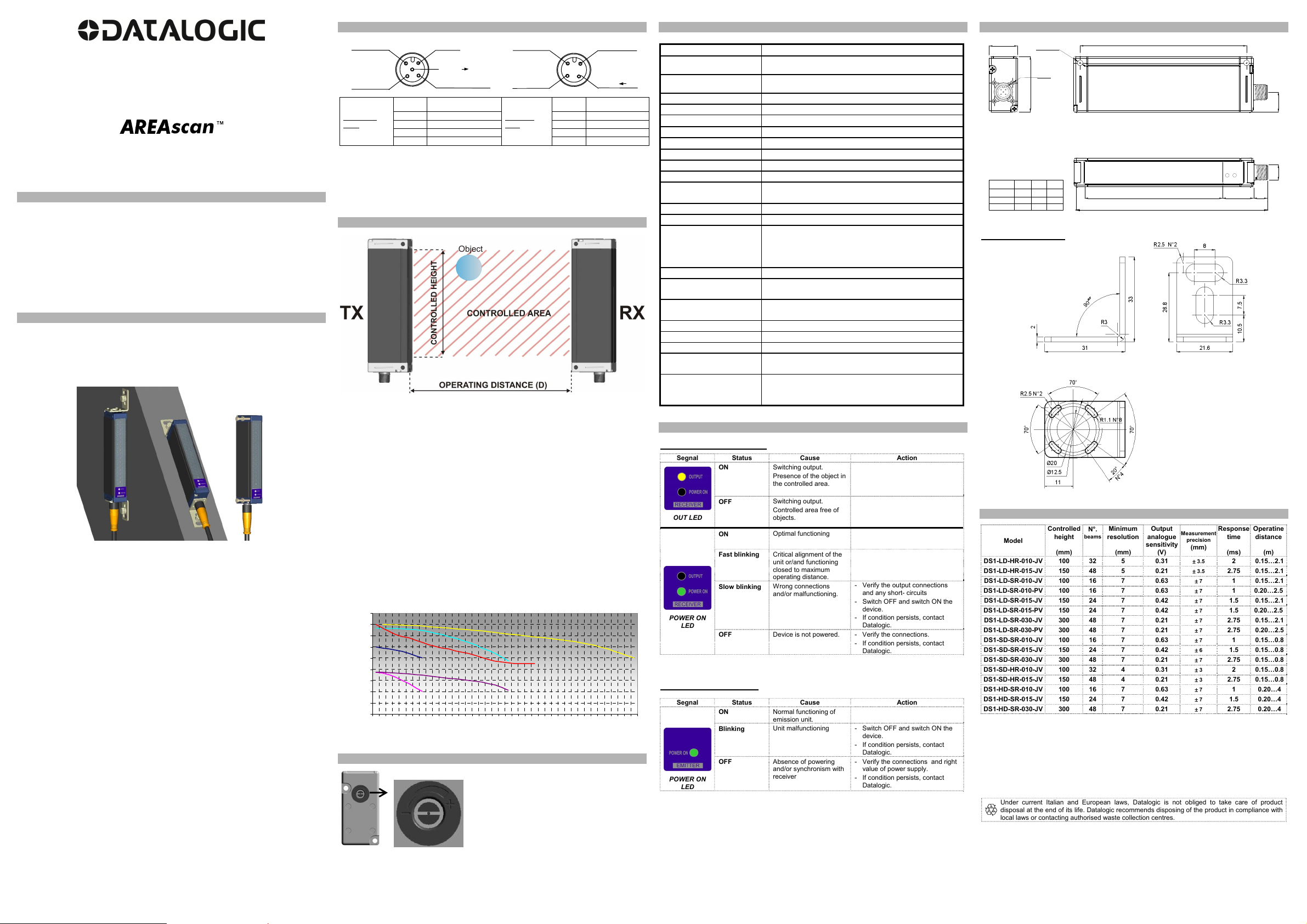
INSTALLATION MODES
General information on device positioning
Align the two receiver (RX) and emitter (TX) units, verifying that their distance is inside
the device operating distance, in a parallel manner, placing the sensitive sides one in
front of the other, with the connectors oriented on the same side. The critical alignment
of the unit will be signalled by the fast blinking of the green receiver LED.
Mount the receiver and emitter units on rigid supports which are not subject to strong
vibrations, using specific fixing brackets and /or the holes present on the device lids.
Precautions to respect when choosing and installing the device
Choose the device according to the minimum object to detect and the maximum
controlled area requested (= operating distance x controlled height);
In agroindustrial applications, the compatibility of light grid housing material and any
chemical agents used in the production process has to be verified with the assistance
of the DATALOGIC technical sales support department;
The AREAscan
TM
light grids are NOT safety devices, and so MUST NOT be used in
the safety control of the machines where installed.
Moreover the following points have to be considered:
- avoid installation near very intense and / or blinking light sources, in particular near to
the receiver unit;
- the presence of strong electromagnetic disturbances can condition the correct
functioning of the device; this condition has to be carefully evaluated and checked with
the DATALOGIC technical sales support department;
- the presence of smoke, fog and suspended dust in the working environment can
reduce the operating distance of the device;
- strong and frequent temperature variations, with very low peak temperatures, can
generate a thin condensation layer on the optics surfaces, compromising the correct
functioning of the device;
- reflecting surfaces near the luminous beam of the AREAscan
TM
device (above, under
or lateral) can cause passive reflections able to compromise object detection inside the
controlled area.
if different devices have to be installed in adjacent areas, the emitter of one unit must not
interfere with the receiver of the other unit.
General information relative to object detection and measurement
For a correct object detection and / or measurement, the object has to pass completely
through the controlled area; testing the correct detection before beginning the process is
suggested.
CONNECTIONS
4
5
3
1
2
0 V
ANALOGUE
OUTPUT
SYNC ( TX)
+24 Vdc
SWITCHING
OUTPUT
3
4
2
1
0 V
+24 Vdc
SYNC ( RX)
NOT USED
RECEIVER
(RX):
M12
5-pole connector
1 – brown: +24 Vdc
EMITTER
(TX):
M12
4-pole connector
1 – brown: +24 Vdc
2 – white: Analogue output 2 – white: Not used
3 – blue: 0 V 3 – blue: 0 V
4 –black: Switching output 4 – black: SYNC
5 – grey: SYNC
Shielded cables are not foreseen in the standard connection
Ground connection of the two units is not necessary
Use the same power supply for both units: for a correct functioning it’s necessary that
both units TX and RX have the same voltage reference 0V
FUNCTIONING AND PERFORMANCES
The beam interruption due to the passage of an object inside the controlled area caused
the closing of the switching output and the variation of the device analogue output signal.
Small objects can be detected (reaching dimensions of only 5 mm) and determine linear
measurements with a 3 mm error in best cases.
In particular, the switching output is always activated when at least one beam is
obscured. The status variation is signalled by the yellow receiver LED that turns on.
The analogue output value (0-10 V) is proportional to the number of obscured beams (0V
means that no beam is interrupted, 10V all beams interrupted)
The device does not require calibration; periodical checks of the resolution and / or
measurement are however suggested.
The blinking of the green receiver LED (stability function) signals the critical alignment of
the units and / or the functioning outside or near the maximum operating distance. In
optimal conditions the LED remains on continuously.
The two units are synchronised via cable (SYNC wire); precarious connections or
induced disturbances on the synchronism line can cause device malfunctioning or a
temporary blocking.
The diagrams, given below, show the typical minimum resolution trend of each model, SR
(standard resolution) and HR (high resolution), in according to the operating distance (D).
For DS1-LD-SR-XXX-PV, the minimum resolution at a particular operating distance is to
be intended with the trimmer calibrated near commutation threshold for that distance.
2
3
4
5
6
7
8
9
10
11
15
0
30
0
50
0
700
900
1100
1300
1500
1
7
00
1
9
00
2
1
00
2
3
00
2
5
00
2
70
0
2
90
0
3
100
3
300
3500
3700
3
9
00
Operating distance (D) mm
Resolution minimum (R) mm
DS1- HD-SR-XXX -JV
DS1-LD-SR-XXX-JV
DS1-LD-HR-XXX-JV
DS1-SD-SR-XXX-JV
DS1-SD-HR-XXX-JV
DS1-LD-SR-XXX-PV
EMISSION POWER REGULATION (only DS1-LD-SR-XXX-PV)
Rotate the trimmer clockwise to the limit (maximum emission), then align RX and TX at
the required operating distance (LED OUT off); decrease emission power rotating the
trimmer counterclockwise until the output switches (LED OUT off) or the limit is reached
(minimum emission); in the first case, rotate the trimmer clockwise until the output
switches again and LED OUT remains off.
TECHNICAL DATA
Power supply:
24 Vdc 15%
Consumption on emitting
unit
(TX):
150 mA max.
Consumption on receiving
unit (RX):
50 mA max without load
Switching output:
1 PNP output
Switching output current:
100 mA; short-circuit protection
Output saturation voltage:
1.5 V at T=25 °C
Analogue output:
0-10V proportional to obscured beams
Analogue output current:
10 mA max. (1K minimum resistive load)
Minimum resolution:
refer to “Specifications” table
Measurement precision:
± 3.5 mm (refer to “Specifications” table)
Response time:
1 ms (refer to “Specifications” table)
Indicators:
RX: OUT LED (yellow) / POWER ON LED (green)
TX: POWER ON LED (green)
Operating temperature:
0…+ 50 °C
Storage temperature:
-25…+ 70 °C
Operating distance
(typical values):
DS1-SD-XX-XXX-JV: 0.15…0.8 m
DS1-LD-XX-XXX-JV: 0.15…2.1 m
DS1-LD-SR-XXX-PV: 0.20…2.5 m
DS1-HD-XX-XXX-JV: 0.20…4.0 m
Emission type:
Infrared (880 nm)
Vibrations:
0.5 mm amplitude, 10 … 55 Hz frequency, for
every axis (EN60068-2-6)
Shock resistance:
11 ms (30 G) 6 shock for every axis (EN60068-2-
27)
Housing material:
Black electro-painted aluminium
Lens material:
PMMA
Mechanical protection:
IP65 (EN 60529)
Connections:
M12 4-pole connector for TX
M12 5-pole connector for RX
Weight:
300 g. (DS1-xx-010-xx)
400 g. (DS1-xx-015-xx)
600 g. (DS1-xx-030-xx)
DIAGNOSTICS
RECEIVING UNIT (RX):
Segnal Status Cause Action
OUT LED
ON
Switching output.
Presence of the object in
the controlled area.
OFF
Switching output.
Controlled area free of
objects.
POWER ON
LED
ON
Optimal functioning
Fast blinking
Critical alignment of the
unit or/and functioning
closed to maximum
operating distance.
Slow blinking
Wrong connections
and/or malfunctioning.
- Verify the output connections
and any short- circuits
- Switch OFF and switch ON the
device.
- If condition persists, contact
Datalogic.
OFF
Device is not powered. - Verify the connections.
- If condition persists, contact
Datalogic.
EMITTING UNIT (TX):
Segnal Status Cause Action
POWER ON
LED
ON
Normal functioning of
emission unit.
Blinking
Unit malfunctioning - Switch OFF and switch ON the
device.
- If condition persists, contact
Datalogic.
OFF
Absence of powering
and/or synchronism with
receiver
- Verify the connections and right
value of power supply.
- If condition persists, contact
Datalogic.
DIMENSIONS
22
43.2
M2 N°4
L3
Ø4.5 N°2
M12
24L2
10.8
L1
mm
L2 L3
DS1-010
DS1-015
DS1-030
150.1
200.1
350.1
107
157
307
129.1
179.1
329.1
L1
15.5
FIXING BRACKET
The fixing bracket is supplied with the product.
SPECIFICATIONS
Model
Controlled
height
(mm)
N°.
beams
Minimum
resolution
(mm)
Output
analogue
sensitivity
(V)
Measurement
precision
(mm)
Response
time
(ms)
Operatine
distance
(m)
DS1-LD-HR-010-JV 100 32 5 0.31
3.5
2 0.15…2.1
DS1-LD-HR-015-JV 150 48 5 0.21
3.5
2.75 0.15…2.1
DS1-LD-SR-010-JV 100 16 7 0.63
7
1 0.15…2.1
DS1-LD-SR-010-PV 100 16 7 0.63
7
1 0.20…2.5
DS1-LD-SR-015-JV 150 24 7 0.42
7
1.5 0.15…2.1
DS1-LD-SR-015-PV 150 24 7 0.42
7
1.5 0.20…2.5
DS1-LD-SR-030-JV 300 48 7 0.21
7
2.75 0.15…2.1
DS1-LD-SR-030-PV 300 48 7 0.21
7
2.75 0.20…2.5
DS1-SD-SR-010-JV 100 16 7 0.63
7
1 0.15…0.8
DS1-SD-SR-015-JV 150 24 7 0.42
6
1.5 0.15…0.8
DS1-SD-SR-030-JV 300 48 7 0.21
7
2.75 0.15…0.8
DS1-SD-HR-010-JV 100 32 4 0.31
3
2 0.15…0.8
DS1-SD-HR-015-JV 150 48 4 0.21
3
2.75 0.15…0.8
DS1-HD-SR-010-JV 100 16 7 0.63
7
1 0.20…4
DS1-HD-SR-015-JV 150 24 7 0.42
7
1.5 0.20…4
DS1-HD-SR-030-JV 300 48 7 0.21
7
2.75 0.20…4
Datalogic S.r.l.
Via S. Vitalino 13 - 40012 Calderara di Reno - Italy
Tel: +39 051 3147011 - Fax: +39 051 3147205 - www.datalogic.com
Helpful links at www.datalogic.com: Contact Us, Terms and Conditions, Support.
The warranty period for this product is 36 months. See General Terms and Conditions of Sales for
further details.
Under current Italian and European laws, Datalogic is not obliged to take care of product
disposal at the end of its life. Datalogic recommends disposing of the product in compliance with
local laws or contacting authorised waste collection centres.
© 2009 - 2017 Datalogic S.p.A. and/or its affiliates
ALL RIGHTS RESERVED. Without limiting the
rights under copyright, no part of this documentation may be reproduced, stored in or introduced into a
retrieval system, or transmitted in any form or by any means, or for any purpose, without the express
written permission of Datalogic S.p.A. and/or its affiliates. Datalogic and the Datalogic logo are registered
trademarks of Datalogic S.p.A. in many countries, including the U.S.A. and the E.U. All other trademarks
and brands are property of their respective owners. Datalogic reserves the right to make modifications
and improvements without prior notification.
826003144 Rev.E
The emitter is equiped with a trimmer which let
user change the emission power. The operating
distance increases rotating the trimmer clockwise.
The emission power reduction it is useful to
decrease passive reflections when the maximum
operating distance it is not required. Trimmer
rotation is limited to 260°. Do not apply a torque
greater than 35 Nmm.
 Loading...