


Matrix 220™
Image Based Reader
Product Reference Guide
Datalogic S.r.l.
Via S. Vitalino, 13
40012 Calderara di Reno — Italy
Tel. +39 051 3147011
Fax +39 051 3147205
Matrix 220™ Product Reference Guide
Original Instructions
Ed.: 11/2018
This manual refers to software version 1.6.0 and later.
© 2018 Datalogic S.p.A. and/or its affiliates
ALL RIGHTS RESERVED. Without limiting the rights under copyright, no part of this documentation may be reproduced, stored in or introduced into a retrieval system, or transmitted in any form or by any means, or for any purpose, without the express written permission of Datalogic S.p.A. and/or its affiliates.
Datalogic and the Datalogic logo are registered trademarks of Datalogic S.p.A. in many countries, including the U.S.A. and the E.U.
Matrix 220, ID-NET, DL.CODE and X-PRESS are trademarks of Datalogic S.p.A.and/or its affiliates. All other trademarks and bands are property of their respective owners.
Datalogic shall not be liable for technical or editorial errors or omissions contained herein, nor for incidental or consequential damages resulting from the use of this material.

|
Table Of Contents |
REFERENCES ........................................................................................................................................................................ |
VII |
Reference Documentation ............................................................................................................................................................ |
vii |
Support Through The Website ...................................................................................................................................................... |
vii |
Patents ............................................................................................................................................................................................ |
vii |
Conventions ................................................................................................................................................................................... |
viii |
COMPLIANCE ......................................................................................................................................................................... |
IX |
General .............................................................................................................................................................................................. |
ix |
Power Supply .................................................................................................................................................................................... |
ix |
EMC Compliance ............................................................................................................................................................................... |
ix |
CE Compliance .................................................................................................................................................................................. |
ix |
FCC Compliance ................................................................................................................................................................................. |
x |
EAC Compliance ................................................................................................................................................................................. |
x |
LED Safety .......................................................................................................................................................................................... |
x |
HANDLING.............................................................................................................................................................................. |
XI |
GENERAL VIEW ................................................................................................................................................................... |
XIII |
RAPID CONFIGURATION ............................................................................................................ |
........................................... 1 |
Step 1 - Connect the System .......................................................................................................................................................... |
1 |
CBX100/CBX500 Pinout for Matrix 220 ......................................................................................................................... |
2 |
Step 2 - Mount and Position the Reader ....................................................................................................................................... |
3 |
Step 3 - Aim and Autofocus the Reader ........................................................................................................................................ |
5 |
Step 4 - X-PRESS Configuration ..................................................................................................................................................... |
6 |
Aim ..................................................................................................................................................................................... |
6 |
Setup ................................................................................................................................................................................. |
6 |
Learn .................................................................................................................................................................................. |
6 |
Reset Reader to Factory Default Environment (Optional) ........................................................................................... |
7 |
Step 5 - Installing DL.CODE Configuration Program .................................................................................................................... |
8 |
Device Discovery .............................................................................................................................................................. |
8 |
Step 6 - Device Configuration ....................................................................................................................................................... |
11 |
Automatic or Advanced Setup ...................................................................................................................................... |
11 |
Automatic Setup ............................................................................................................................................................ |
12 |
Advanced Setup .............................................................................................................................................................. |
15 |
Reading Phase ................................................................................................................................................................ |
23 |
Good Read Setup ............................................................................................................................................................ |
24 |
Data Formatting ............................................................................................................................................................. |
25 |
Output Setup .................................................................................................................................................................. |
26 |
Step 7 - Test Mode ......................................................................................................................................................................... |
27 |
Advanced Reader Configuration ................................................................................................................................................... |
28 |
Host Mode Programming ...................................................................................................................................................... |
28 |
INTRODUCTION................................................................................................................... |
................................................. 29 |
Product Description ....................................................................................................................................................................... |
29 |
Standard Application Program ..................................................................................................................................... |
30 |
Programmability ............................................................................................................................................................ |
30 |
Excellent Performance .................................................................................................................................................. |
31 |
Ease of Setup .................................................................................................................................................................. |
31 |
Ease of Use ..................................................................................................................................................................... |
31 |
Flexible Solution ............................................................................................................................................................. |
31 |
Versatility ........................................................................................................................................................................ |
31 |
Industrial Strength ......................................................................................................................................................... |
32 |
Product Reference Guide |
iii |

Indicator and Keypad Button ......................................................................................................................................................... |
32 |
Aiming System ................................................................................................................................................................................ |
34 |
LED Spots ......................................................................................................................................................................................... |
34 |
ID-NET .............................................................................................................................................................................................. |
35 |
X-PRESS Human Machine Interface ............................................................................................................................................. |
36 |
X-PRESS Functions ................................................................................................................................................................ |
37 |
Test Mode ........................................................................................................................................................................ |
37 |
Focus/Aim ....................................................................................................................................................................... |
38 |
Setup ................................................................................................................................................................................ |
38 |
Learn ................................................................................................................................................................................ |
38 |
Diagnostic Indication .............................................................................................................................................................. |
39 |
Model Description ........................................................................................................................................................................... |
39 |
Internal Lighting Systems ...................................................................................................................................................... |
40 |
Accessories ...................................................................................................................................................................................... |
40 |
Application Examples ..................................................................................................................................................................... |
42 |
Document Handling ................................................................................................................................................................ |
42 |
Deformed or Overprinted Code Reading .............................................................................................................................. |
42 |
Direct Part Marking ................................................................................................................................................................ |
43 |
Ink-Jet Printing Technology ................................................................................................................................................... |
43 |
Laser Marking/Etching Technology ...................................................................................................................................... |
44 |
INSTALLATION..................................................................................................................................................................... |
45 |
Package Contents ........................................................................................................................................................................... |
45 |
Mechanical Dimensions ................................................................................................................................................................. |
46 |
Mounting And Positioning Matrix 220 ......................................................................................................................................... |
51 |
Mounting Accessory Covers .......................................................................................................................................................... |
54 |
ELECTRICAL CONNECTIONS ............................................................................................................................................... |
55 |
CBX Connection Box Pinout ........................................................................................................................................................... |
55 |
Power Supply ................................................................................................................................................................................... |
57 |
Standard Models ..................................................................................................................................................................... |
57 |
Power Over Ethernet (PoE) Models ...................................................................................................................................... |
57 |
Main Serial Interface ...................................................................................................................................................................... |
58 |
RS232 Interface ....................................................................................................................................................................... |
58 |
RS422 Full Duplex Interface ................................................................................................................................................... |
59 |
ID-NET Interface ............................................................................................................................................................................. |
60 |
ID-NET Cables .......................................................................................................................................................................... |
60 |
ID-NET Response Time .......................................................................................................................................................... |
61 |
ID-NET Network Termination ................................................................................................................................................ |
62 |
ID-NET Connection Diagrams ................................................................................................................................................ |
62 |
Auxiliary RS232 Interface ............................................................................................................................................................... |
65 |
Inputs ............................................................................................................................................................................................... |
66 |
External Trigger Input Connections Using Matrix 220 Power ............................................................................................ |
67 |
External Trigger Input Connections Using External Power ................................................................................................ |
69 |
Input 2 Connections Using Matrix 220 Power ..................................................................................................................... |
69 |
Input 2 Connections Using External Power ......................................................................................................................... |
70 |
Input 3 Connections (CBX500 Only) ...................................................................................................................................... |
71 |
Outputs ............................................................................................................................................................................................ |
71 |
Output 1 and 2 Connections Using Matrix 220 Power ........................................................................................................ |
72 |
Output 3 Connections Using Matrix 220 Power (CBX500 Only) ......................................................................................... |
74 |
On-Board Ethernet Interface ......................................................................................................................................................... |
75 |
User Interface - Serial Host ........................................................................................................................................................... |
75 |
TYPICAL LAYOUTS............................................................................................................................................................... |
76 |
Ethernet Connection ....................................................................................................................................................................... |
77 |
Serial Connection ............................................................................................................................................................................ |
79 |
Fieldbus Connection ....................................................................................................................................................................... |
80 |
Pass-Through .................................................................................................................................................................................. |
81 |
ID-NET Multidata Network (Pass-Through) ................................................................................................................................ |
82 |
ID-NET Synchronized Network ...................................................................................................................................................... |
83 |
READING FEATURES........................................................................................................................................................... |
86 |
FOV Calculation ............................................................................................................................................................................... |
86 |
iv |
Matrix 220 |

Global FOV Diagrams ..................................................................................................................................................................... |
87 |
7 mm Models (38°Horizontal View Angle) .......................................................................................................................... |
88 |
12 mm Models (24° Horizontal View Angle) ....................................................................................................................... |
89 |
Reading Diagrams .......................................................................................................................................................................... |
90 |
Matrix 220 (7 mm models) 1D Codes ................................................................................................................................... |
91 |
Matrix 220 (7 mm models) 2D Codes ................................................................................................................................... |
93 |
Matrix 220 (12 mm models) 1D Codes ................................................................................................................................. |
94 |
Matrix 220 (12 mm models) 2D Codes ................................................................................................................................. |
96 |
Maximum Line Speed and Exposure Time Calculations ............................................................................................................ |
97 |
SOFTWARE CONFIGURATION............................................................................................................................................. |
99 |
DL.CODE System Requirements ................................................................................................................................................... |
99 |
Reader Configuration ................................................................................................................................................................... |
100 |
Auto-Calibration ................................................................................................................................................................... |
100 |
Manual Calibration ............................................................................................................................................................... |
102 |
Under-exposure ........................................................................................................................................................... |
102 |
Over-exposure .............................................................................................................................................................. |
103 |
Moving code out of the Field of View ......................................................................................................................... |
104 |
Multi Image Acquisition Settings ............................................................................................................................................... |
105 |
Automatic Image Settings Selection .................................................................................................................................. |
106 |
External Image Settings Selection ..................................................................................................................................... |
107 |
Image Cropping ............................................................................................................................................................................ |
109 |
Direct Part Marking Applications ............................................................................................................................................... |
112 |
Matrix 220 Recommended Illumination for DPM ............................................................................................................. |
113 |
Illumination Examples for DPM Applications ................................................................................................................... |
114 |
Code Positioning with Respect to Illumination ........................................................................................................ |
114 |
Code Contrast ............................................................................................................................................................... |
115 |
Image Filter ........................................................................................................................................................................... |
116 |
Pass-Through Configurations .................................................................................................................................................... |
120 |
Internal Network Configurations ............................................................................................................................................... |
122 |
Master Configuration ........................................................................................................................................................... |
122 |
Multidata ID-NET Network Configurations ....................................................................................................................... |
125 |
Synchronized ID-NET Network Configurations ................................................................................................................ |
130 |
Verify Master/Slave Synchronized Configuration ............................................................................................................ |
134 |
Backup and Restore Through DL.CODE ..................................................................................................................................... |
137 |
Backup ................................................................................................................................................................................... |
138 |
Restore .................................................................................................................................................................................. |
139 |
Replacement ......................................................................................................................................................................... |
140 |
Restore Defaults .......................................................................................................................................................................... |
140 |
Restore Default Startup Configuration .............................................................................................................................. |
140 |
Restore Default Environment ............................................................................................................................................. |
141 |
Restore Factory Defaults .................................................................................................................................................... |
142 |
Diagnostic Alarms ........................................................................................................................................................................ |
142 |
Statistics ....................................................................................................................................................................................... |
143 |
BM150 Display Module Configuration and Messages ............................................................................................................. |
144 |
Configuration Through DL.CODE ........................................................................................................................................ |
144 |
Accessing the HMI Interface Through Keypad and Display Menu .................................................................................. |
145 |
Display Messages ................................................................................................................................................................ |
147 |
BM150 Backup and Restore Procedure ............................................................................................................................. |
150 |
MAINTENANCE .................................................................................................................................................................. |
152 |
Cleaning ......................................................................................................................................................................................... |
152 |
TROUBLESHOOTING .......................................................................................................................................................... |
153 |
General Guidelines ....................................................................................................................................................................... |
153 |
TECHNICAL FEATURES...................................................................................................................................................... |
156 |
Electrical Features ....................................................................................................................................................................... |
156 |
Optical Features ........................................................................................................................................................................... |
157 |
Environmental Features .............................................................................................................................................................. |
157 |
Physical Features ......................................................................................................................................................................... |
158 |
Software Features ....................................................................................................................................................................... |
158 |
ALTERNATIVE CONNECTIONS ...................................................................................................................... |
159 |
Product Reference Guide |
v |

Power, Com and I/O Connector for Standard Models ............................................................................................................. |
159 |
Com and Trigger Connector for PoE Models ............................................................................................................................. |
160 |
On-Board Ethernet Connector .................................................................................................................................................... |
161 |
Standard Models .................................................................................................................................................................. |
161 |
Power over Ethernet (PoE) Models .................................................................................................................................... |
162 |
ID-NET Network Termination ..................................................................................................................................................... |
162 |
Inputs ............................................................................................................................................................................................ |
163 |
Outputs ......................................................................................................................................................................................... |
163 |
User Interface - Serial Host ........................................................................................................................................................ |
166 |
GLOSSARY........................................................................................................................................................................... |
167 |
vi |
Matrix 220 |

References
Reference Documentation
The documentation related to the Matrix 220 is listed below:
•This Product Reference Guide
•DL.CODE User’s Manual
•DL.CODE Help Online
Support Through The Website
Datalogic provides several services as well as technical support through its website. Log on to www.datalogic.com and click on the SUPPORT link which gives you access to:
•Downloads by selecting your product model from the dropdown list in the Search by Product field for specific Data Sheets, Manuals, Software & Utilities, and Drawings;
•Repair Program for On-Line Return Material Authorizations (RMAs) plus RepairCenter contact information;
•Customer Service containing details about Maintenance Agreements;
•Technical Support through email or phone.
Patents
See www.patents.datalogic.com for patent list.
This product is covered by one or more of the following patents:
Design patents: EP004735694
Utility patents: EP0996284B1, EP0999514B1, EP1014292B1, EP1128315B1, EP1396811B1, EP1413971B1, EP2517148B1, EP2649555B1, JP4435343B2, JP4571258B2, US6512218, US6616039, US6808114, US6997385, US7053954, US7387246, US7433590, US8058600, US8368000, US8888003, US8915443, US9268982, US9430689, US9798948, ZL200980163411.X
Product Reference Guide |
vii |

References
Conventions
This symbol alerts the user they are about to perform a dangerous action that could result in personal injury as well as damage to the device if not performed correctly. Examples involve exposure to dangerous levels of voltage or electrical shock hazards.
WARNING
This symbol identifies a hazard or procedure that, if incorrectly performed, could cause equipment damage. It is also used to bring the user’s attention to details that are considered IMPORTANT.
CAUTION
This symbol draws attention to details or procedures that may be useful in improving,
maintaining, or enhancing the performance of the hardware or software being dis-
 cussed. NOTE
viii |
Matrix 220 |

Compliance
General
For installation, use and maintenance it is not necessary to open the reader.
Only connect Ethernet and dataport connections to a network which has routing only within the plant or building and no routing outside the plant or building
Power Supply
ATTENTION: READ THIS INFORMATION BEFORE INSTALLING THE PRODUCT This product is intended to be installed by Qualified Personnel only.
This product is intended to be connected to a UL Listed Computer (LPS or “Class 2”) which supplies power directly to the reader, or a UL Listed Direct Plug-in Power Unit (rated 10 to 30 V, minimum 1 A) marked LPS or “Class 2”, or Power over Ethernet source Device supplied by UL Listed Direct Plug-in Power Unit marked LPS or “Class 2”.
EMC Compliance
In order to meet the EMC requirements:
•connect reader chassis to the plant earth ground by means of a flat copper braid shorter than 100 mm;
•connect pin "Earth" of the CBX connection box to a good Earth Ground;
•for direct connections, connect your cable shield to the locking ring nut of the connector.
CE Compliance
CE marking states the compliance of the product with essential requirements listed in the applicable European directive. Since the directives and applicable standards are subject to continuous updates, and since Datalogic promptly adopts these updates, therefore the EU declaration of conformity is a living document. The EU declaration of conformity is available for competent authorities and customers through Datalogic commercial reference contacts. Since April 20th, 2016 the main European directives applicable to Datalogic products require inclusion of an adequate analysis and assessment of the risk(s). This evaluation was carried out in relation to the applicable points of the standards listed in the Declaration of Conformity. Datalogic products are mainly designed for integration purposes into more complex systems. For this reason it is under
Product Reference Guide |
ix |

Compliance
the responsibility of the system integrator to do a new risk assessment regarding the final installation.
Warning
This is a Class A product. In a domestic environment this product may cause radio interference in which case the user may be required to take adequate measures.
FCC Compliance
Modifications or changes to this equipment without the expressed written approval of Datalogic could void the authority to use the equipment.
This device complies with PART 15 of the FCC Rules. Operation is subject to the following two conditions: (1) This device may not cause harmful interference, and (2) this device must accept any interference received, including interference which may cause undesired operation.
This equipment has been tested and found to comply with the limits for a Class A digital device, pursuant to part 15 of the FCC Rules. These limits are designed to provide reasonable protection against harmful interference when the equipment is operated in a commercial environment. This equipment generates, uses, and can radiate radio frequency energy and, if not installed and used in accordance with the instruction manual, may cause harmful interference to radio communications. Operation of this equipment in a residential area is likely to cause harmful interference in which case the user will be required to correct the interference at his/her own expense.
EAC Compliance
Customs Union:
The CU Conformity certification has been achieved; this allows the Product to bear the Eurasian Mark of conformity.
LED Safety
LED emission according to EN 62471.
x |
Matrix 220 |
Handling
The Matrix 220 is designed to be used in an industrial environment and is built to withstand vibration and shock when correctly installed, however it is also a precision product and therefore before and during installation it must be handled correctly to avoid damage.
•avoid that the readers are dropped (exceeding shock limits)
•do not fine tune the positioning by striking the reader or bracket.
Product Reference Guide |
xi |

Handling
•do not weld the reader into position which can cause electrostatic, heat or reading window damage.
•do not spray paint near the reader which can cause reading window damage.
xii |
Matrix 220 |
General View

|
|
|
|
|
Standard Model |
PoE Model |
|
|
|
|
|
|
|
|
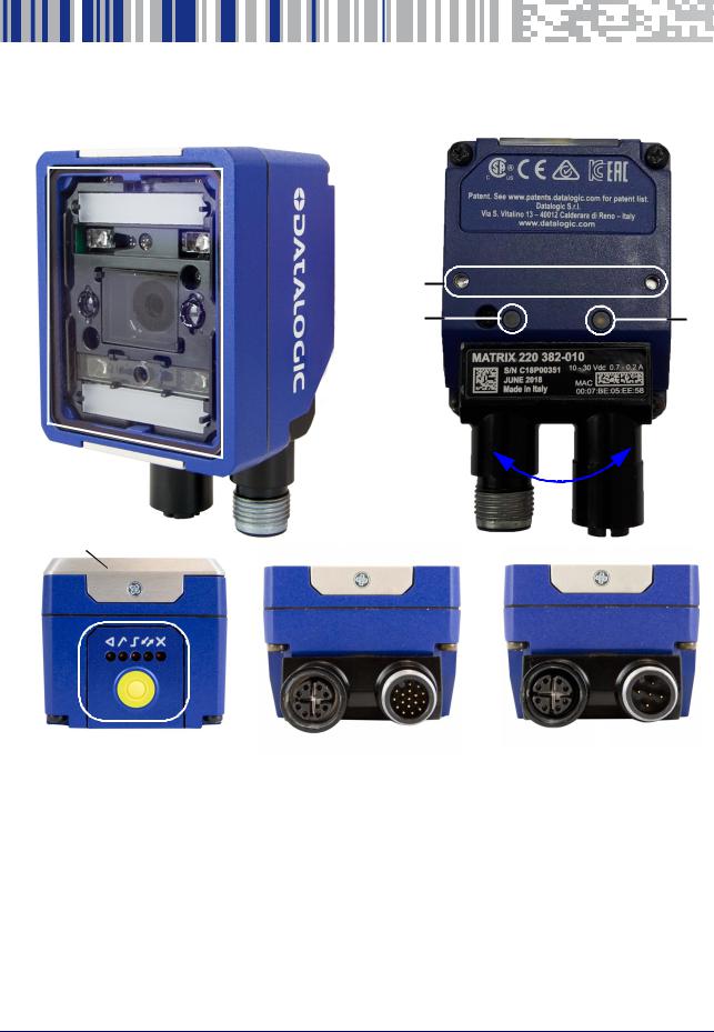
General View of DPM Models |
|
|||
|
|
|
|
|
|
|
Reading Window |
|
|
Accessory Window Cover |
|
|
|
|
|
|
|
|
Mounting Holes (2) |
|
|
X-PRESS Interface |
|
|
|
|
|
|
|
|
Power On LED |
|
|
Ethernet Connector |
|
|
|
|
|
|
|
|
Ethernet Connection LED |
|
|
Power, COM, I/O Connector |
|
|
|
|
|
|
|
|
90° Rotating Connector Block |
|
|
Power Over Ethernet Connector |
|
|
|
|
|
|
|
|
|
|
|
COM, Trigger Connector |
|
|
|
|
|
|
|
Product Reference Guide |
xiii |
General View

|
|
|
|
|
Standard Model |
PoE Model |
|
|
|
|
|
|
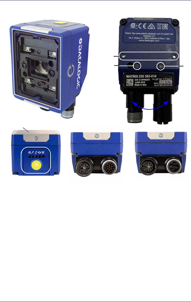
General View of Standard Models
|
Reading Window |
|
Accessory Window Cover |
|
|
|
|
|
Mounting Holes (2) |
|
X-PRESS Interface |
|
|
|
|
|
Power On LED |
|
Ethernet Connector |
|
|
|
|
|
Ethernet Connection LED |
|
Power, COM, I/O Connector |
|
|
|
|
|
90° Rotating Connector Block |
|
Power Over Ethernet Connector |
|
|
|
|
|
|
|
COM, Trigger Connector |
|
|
|
|
xiv |
Matrix 220 |
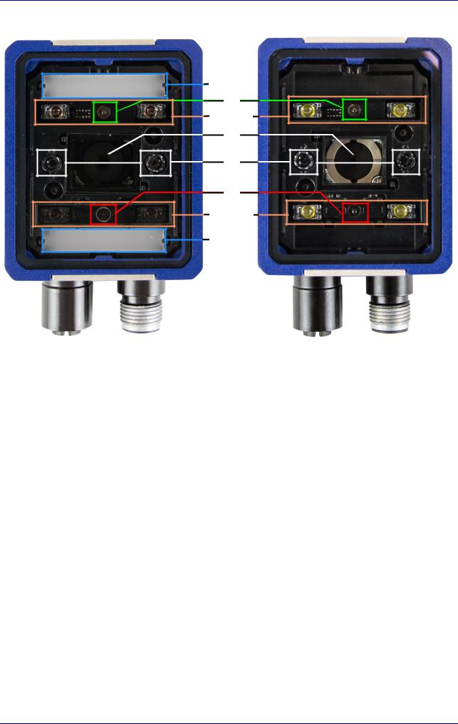
General View
DPM Models |
Standard Models |
Reading Window Details
|
Lens |
|
Non Polarized Illuminator |
|
|
|
|
|
LED Aiming System |
|
Polarized Illuminator |
|
|
|
|
|
Red Spot (No Read) |
|
Diffused Illuminators |
|
|
|
|
|
Green Spot (Good Read) |
|
Standard Illuminators (Top/Bottom) |
|
|
|
|
Product Reference Guide |
xv |

General View
|
|
|
|
|
|
X-PRESS Interface Details |
|
|
|
|
|
|
Normal Operation |
|
X-PRESS Configuration |
|
|
|
|
|
Ready |
|
Learn |
|
|
|
|
|
Good |
|
Setup |
|
|
|
|
|
Trigger |
|
Aim |
|
|
|
|
|
COM |
|
Test |
|
|
|
|
|
Status |
|
|
|
|
|
|
|
Push-button |
|
|
|
|
|
|
xvi |
Matrix 220 |
Chapter 1
Rapid Configuration
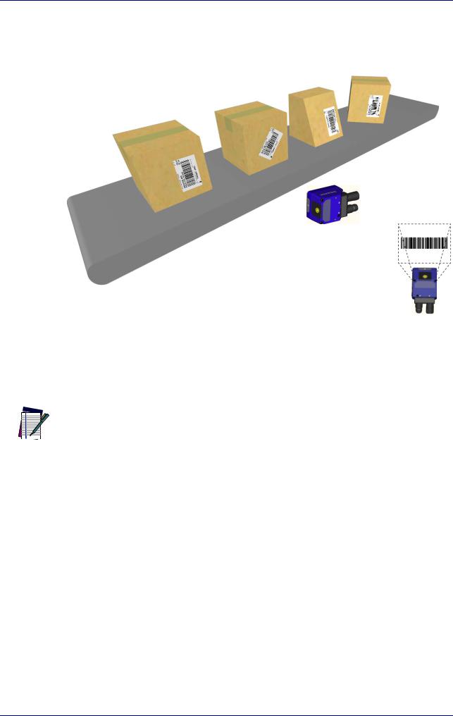
Step 1 - Connect the System
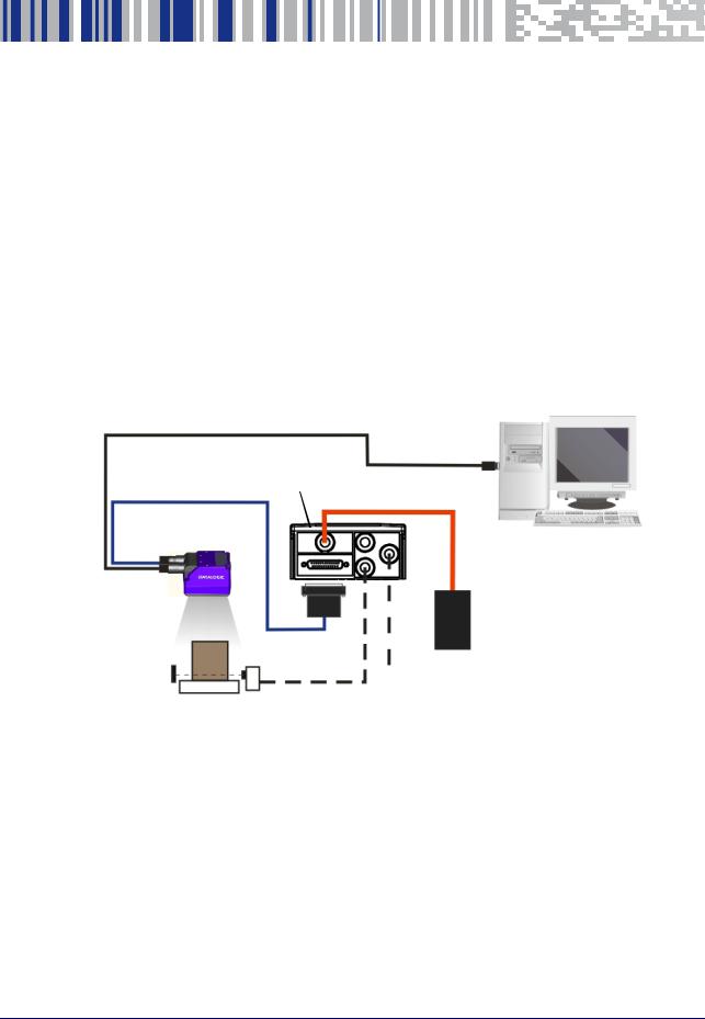
To connect the system in a Stand Alone configuration, you need the hardware indicated in Figure 1. In this layout the data is transmitted to the Host on the Ethernet interface. Data can also be transmitted on the RS232 main and/or auxiliary interface independently from the Ethernet interface selection.
When One Shot or Phase Mode Operating mode is used, the reader is activated by an External Trigger (photoelectric sensor) when the object enters its reading zone.
Host
CAB-ETH-M0x
CAB-DSxx-S CBX
Matrix 220 |
|
Alone |
PG6000 |
|
Ethernet Interface
Auxiliary Serial Interface (RS232 - Data Monitor)
External Trigger (for One Shot or Phase Mode)
Figure 1 - Matrix 220 in Stand Alone Layout
Product Reference Guide |
1 |

Rapid Configuration
CBX100/CBX500 Pinout for Matrix 220
The table below gives the pinout of the CBX100/CBX500 terminal block connectors. Use this pinout when the Matrix 220 reader is connected by means of the CBX100/CBX500:
Group |
Label |
Description |
|
|
|
|
|
|
Input Power |
Vdc |
Power Supply Input Voltage + |
|
|
|
|
GND |
Power Supply Input Voltage - |
|
|
|
|
Earth |
Protection Earth Ground |
|
|
|
Inputs |
+V |
Power Source - External Trigger |
|
|
|
|
I1A |
External Trigger A (polarity insensitive) |
|
|
|
|
I1B |
External Trigger B (polarity insensitive) |
|
|
|
|
-V |
Power Reference - External Trigger |
|
|
|
I |
+V |
Power Source - Inputs |
|
|
|
|
I2A |
Input 2 A (polarity insensitive) |
|
|
|
|
I2B |
Input 2 B (polarity insensitive) |
|
|
|
|
-V |
Power Reference - Inputs |
|
|
|
Outputs |
+V |
Power Source - Outputs |
|
|
|
|
-V |
Power Reference - Outputs |
|
|
|
|
O1+ |
Output 1 + opto-isolated and polarity sensitive |
|
|
|
|
O1- |
Output 1 - opto-isolated and polarity sensitive |
|
|
|
|
O2+ |
Output 2 + opto-isolated and polarity sensitive |
|
|
|
|
O2- |
Output 2 - opto-isolated and polarity sensitive |
|
|
|
|
O3A |
Output 3 - opto-isolated (only available through CBX500) |
|
|
|
Auxiliary Interface |
TX |
Transmit Data |
|
|
|
|
RX |
Receive Data |
|
|
|
|
SGND |
Auxiliary Interface Signal Ground |
|
|
|
ID-NET |
REF |
Network Reference |
|
|
|
|
ID+ |
ID-NET network data + |
|
|
|
|
ID- |
ID-NET network data - |
|
|
|
|
Shield |
Network Cable Shield |
|
|
|
|
|
|
Main Interface |
RS232 |
RS422 Full Duplex |
|
|
|
|
TX |
TX+ |
|
|
|
|
RX |
*RX+ |
|
|
|
|
- |
TX- |
|
|
|
|
- |
*RX- |
|
|
|
|
SGND |
SGND |
|
|
|
* Do not leave floating, see "RS422 Full Duplex Interface" on page 59 for connection details.
2 |
Matrix 220 |
Step 2 - Mount and Position the Reader
Do not connect GND, SGND and REF to different (external) ground references. GND, SGND and REF are internally connected through filtering circuitry which can be permanently damaged if subjected to voltage drops over 0.8 Vdc.
CAUTION
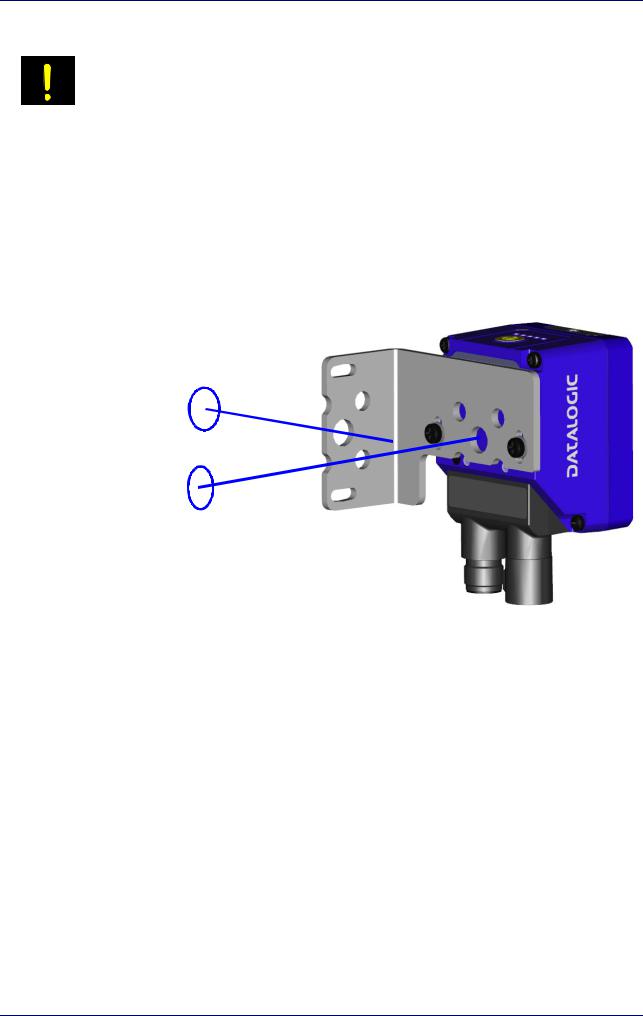
Step 2 - Mount and Position the Reader
1.To mount the Matrix 220, use the mounting brackets to obtain the most suitable position for the reader. The most common mounting configuration is shown in the figure below.
Skew
Tilt
Figure 2 - Positioning with Mounting Bracket
2.When mounting the Matrix 220 take into consideration these three ideal label position angles: Pitch or Skew 10° to 20° and Tilt 0°, although the reader can read a code at any tilt angle provided the code fits into the Field Of View (FOV).
Product Reference Guide |
3 |
Rapid Configuration
|
|
|
Skew |
|
Tilt |
Pitch |
assure at least 10° |
|
Minimize |
|
|
No Pitch, |
any angle |
|
|
inside FOV |
|
|
|
Tilt or Skew |
|
|
|
FOVH
FOVV
Figure 3 - Pitch, Skew and Tilt References
3.Refer to the reading diagrams in Chapter 6, to determine the distance your reader should be positioned at.
Rapid Configuration of the Matrix 220 reader can be made either through the X-
PRESS interface (steps 3-4) which requires no PC connection, or by using the DL.CODE
 Configuration Program (steps 5-6). Select the procedure according to your needs. NOTE
4 |
Matrix 220 |
Step 3 - Aim and Autofocus the Reader
Step 3 - Aim and Autofocus the Reader
Matrix 220 provides a built-in LED aiming system to aid reader positioning. The autofocus feature is also incorporated into this function. The aiming system is accessed through the X-PRESS Interface.
1.Power the reader on. During the reader startup (reset or restart phase), all the LEDs blink for one second. On the reverse side of the reader near the bracket, the “POWER ON” LED (blue) indicates the reader is correctly powered.
2.Place the Grade A Barcode Test Chart in front of the reader at the correct reading distance for your application. See "Global FOV Diagrams" on page 87 for reference.
3.Enter the Aim/Autofocus function by pressing and holding the X-PRESS push button until the Aim LED is on.
4.Release the button to enter the Aim function. The aiming system turns on, and the Autofocus procedure begins, see Figure 4 -. The Aim LED will blink until the procedure is completed.
Within 3 seconds (before the reader flashes), center one of the larger codes between the aiming system indicators (the code must not move during this procedure).
The Autofocus procedure ends when the Reading Distance and PPI values are successfully saved in the reader memory, the Aim LED will stop blinking and Matrix 220 emits 3 high pitched beeps.
If the Autofocus cannot be reached after a timeout of about 3 (three) minutes Matrix 220 will exit without saving the parameters to memory, the Aim LED will stop blinking and in this case Matrix 220 emits a long low pitched beep.
Figure 4 - X-PRESS Interface; Aim/Autofocus Function
You can exit the Aim/Autofocus function at any time by pressing the X-PRESS push
button once. After a short delay the autofocus procedure is cancelled and the aiming
 indicators turn off. NOTE
Product Reference Guide |
5 |

Rapid Configuration
Step 4 - X-PRESS Configuration
Once Matrix 220 is focused at the correct reading distance, you must configure it for optimal code reading relative to your application.
Aim
1.Enter the Aim function by pressing and holding the X-PRESS push button until the Aim LED is on.
2.Release the button to enter the Aim function. The aiming system turns on.
3.Select a single code from your application. Position the code at the center of the FOV (equidistant from the aiming indicators.
The reader may start flashing and try to perform autofocus however this will have no effect on the application specific code; it can be ignored.
Exit the Aim function by pressing the X-PRESS push button once. After a short delay the Aim function is cancelled and the aiming indicators turn off.
Setup
4.Enter the Setup function by pressing and holding the X-PRESS push button until the Setup LED is on.
5.Release the button to enter the Setup function. The Setup LED will blink until the procedure is completed.
The Setup procedure ends when the Image Acquisition parameters are successfully saved in the reader memory, the Setup LED will stop blinking and Matrix 220 emits 3 high pitched beeps.
If the calibration cannot be reached after a timeout of about 5 (five) seconds Matrix 220 will exit without saving the parameters to memory, the Setup LED will stop blinking and in this case Matrix 220 emits a long low pitched beep.
Learn
6.Enter the Learn function by pressing and holding the X-PRESS push button until the Learn LED is on.
7.Release the button to enter the Learn function. The Learn LED will blink until the procedure is completed.
The Learn procedure ends when the Image Processing and Decoding parameters are successfully saved in the reader memory, the Green Spot is activated, the Learn LED will stop blinking and Matrix 220 emits 3 high pitched beeps1.
1.The Code Autolearn procedure will not recognize the following symbologies: Pharmacode, MSI, Standard 2 of 5, Matrix 2 of 5.
6 |
Matrix 220 |

Step 4 - X-PRESS Configuration
If the autolearning cannot be reached after a timeout of about 3 (three) minutes Matrix 220 will exit without saving the parameters to memory, the Learn LED will stop blinking and in this case Matrix 220 emits a long low pitched beep.
The Grade A Barcode Test Chart cannot be used to set the Code 128 symbology (even
though the reader successfully reads the code). Use the application specific code if
 you need to set this symbology. NOTE
When using X-PRESS or the BM150 menu to perform Auto-Learn, only a single code
can be configured (successive Learns will substitute the current code). To configure
 multiple codes, use the DL.CODE Auto-Learn procedure. NOTE
You can always exit from any X-PRESS function at any time by pressing the X-PRESS push button once. After a short delay the procedure is cancelled.
NOTE
If you have used this procedure to configure Matrix 220, go to step 7.
NOTE
Reset Reader to Factory Default Environment (Optional)
If it ever becomes necessary to reset the reader’s Environment parameters to their factory default values, you can perform this procedure by holding the X- PRESS push button pressed while powering up the reader. You must keep the X- PRESS push button pressed until all LEDs blink simultaneously for about 3 seconds. Release and re-press the button during this LED blinking sequence.
All the device’s Environment parameters are reset including the default IP Address. The Matrix 220 emits 3 high pitched beeps and after a few seconds enters run mode.
Any previously saved configurations on the device will remain in memory, but the Default configuration is set as the startup configuration.
Product Reference Guide |
7 |

Rapid Configuration
If you release the button while the LEDs are all on continuously (after the blinking
phase), the reader will enter the Loader program sequence and the LEDs will begin to
 cycle through various patterns. Just cycle power to return to run mode. NOTE
Step 5 - Installing DL.CODE Configuration Program
DL.CODE does not currently support Windows Embedded (often used in industrial PCs and/or PLCs).
CAUTION
DL.CODE is a Datalogic reader configuration tool providing several important advantages:
•Intuitive Graphical User Interface for rapid configuration
•Defined configuration directly stored in the reader
•Discovery and IP address setting features to facilitate remote configuration
•Device Monitoring
To install DL.CODE:
1.On the PC that will be used for configuration, (running Windows 7, 8.1, or 10), download the DL.CODE mini-DVD.zip file. Extract the files maintaining the folder structure and run the start.hta file to access the installation pop-up. Click on the Install DL.CODE link to run the installation program and follow the installation procedure.
To perform a “silent” installation (without user input), see the DL.CODE User’s Guide.
NOTE
2.When the installation is complete the DL.CODE entry is created in the Start>Programs bar under “Datalogic” as well as a desktop icon. Doubleclick the desktop icon to run it.
This configuration procedure assumes a laptop computer, running DL.CODE, is connected to a factory default reader through the Ethernet port.
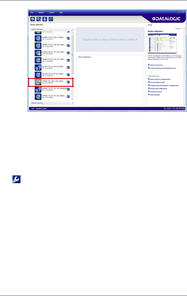
Device Discovery
The User Interface opens and displays a list of all the devices belonging to the Local Area Network. DL.CODE has a discovery feature to accomplish this task.
8 |
Matrix 220 |
Step 5 - Installing DL.CODE Configuration Program
Figure 5 - Device Discovery
The discovery feature will also show devices not belonging to the LAN and display them in grey (see Figure 5 -).
3.First the device must be added to the LAN by aligning its IP Address to the network. The network administrator should provide valid LAN address(es).
4.Find your device in the list by matching its serial number (SN) then click on the device wrench icon to open the Device Environment Configuration window.
5.Change the Ethernet Settings (IP Address, Subnet Mask, Gateway Address etc.) according to the network requirements.
Product Reference Guide |
9 |

Rapid Configuration
Figure 6 - Device Environment Configuration Window
6.Click OK; the device will reappear in the list of Online Devices (in color) meaning it is now part of the LAN and can be configured. The new IP address will also be displayed.
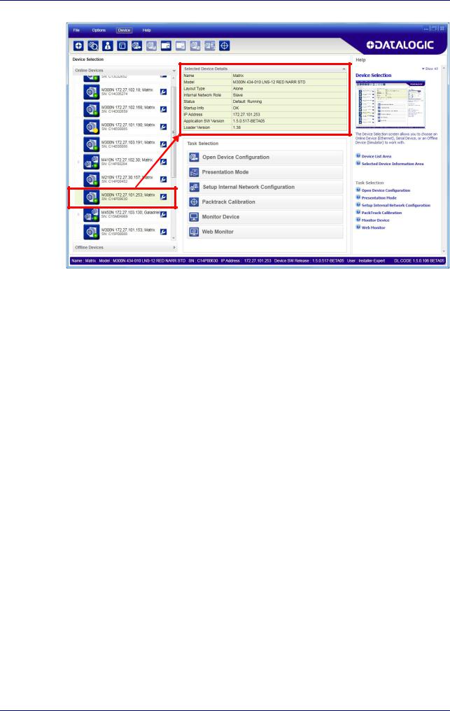
7.Double-click on or drag the device icon into the Selected Device Information Area. Details about the device will be displayed in this area.
10 |
Matrix 220 |
Step 6 - Device Configuration
Figure 7 - DL.CODE Opening Window
Step 6 - Device Configuration
Automatic or Advanced Setup
Automatic Setup provides an automatic procedure for setting: optical/ illumination, reading distance, and code definition parameters to obtain the most stable decoding conditions for a single code symbology based on the images presented to the reader. It can be set to include Image Filters if necessary. See the table below for codes and filters managed by Automatic Setup. Automatic Setup is especially useful for DPM applications.
Product Reference Guide |
11 |

Rapid Configuration
Enabled 1D Codes |
Enabled 2D Codes |
Enabled Filters |
|
|
|
|
|
|
CODE 128 |
DATAMATRIX ECC 200 |
ERODE 3x3, 5x5 and 7x7 |
EAN 128 |
QR |
DILATE 3x3, 5x5 and 7x7 |
CODE 39 |
MICRO QR |
SMOOTHING |
CODE 93 |
AZTEC |
|
CODABAR |
MAXICODE |
|
PDF417 |
DOTCODE |
|
MICRO PDF417 |
|
|
GS1 DATABAR |
|
|
GS1 DATABAR STACKED |
|
|
GS1 DATABAR LIMITED |
|
|
GS1 DATABAR EXPANDED |
|
|
GS1 DATABAR EXPANDED STACKED |
|
|
UPCEAN FAMILY EAN13 |
|
|
UPCEAN FAMILY EAN8 |
|
|
UPCEAN FAMILY UPCA |
|
|
UPCEAN FAMILY UPCE |
|
|
|
|
|
Advanced Setup provides access to the complete array of optical/illumination, focusing adjustment, and code definition parameters that can be fine-tuned semiautomatically and manually to obtain the best results for applications of any complexity.
If your application requires multiple code symbologies, multiple image settings, Code
Grading or other parameter settings for decoding, then use the Advanced Setup, see
 page15. NOTE
Automatic Setup
To begin configuration, the reader must be correctly mounted so that its Field of View covers the application reading area.
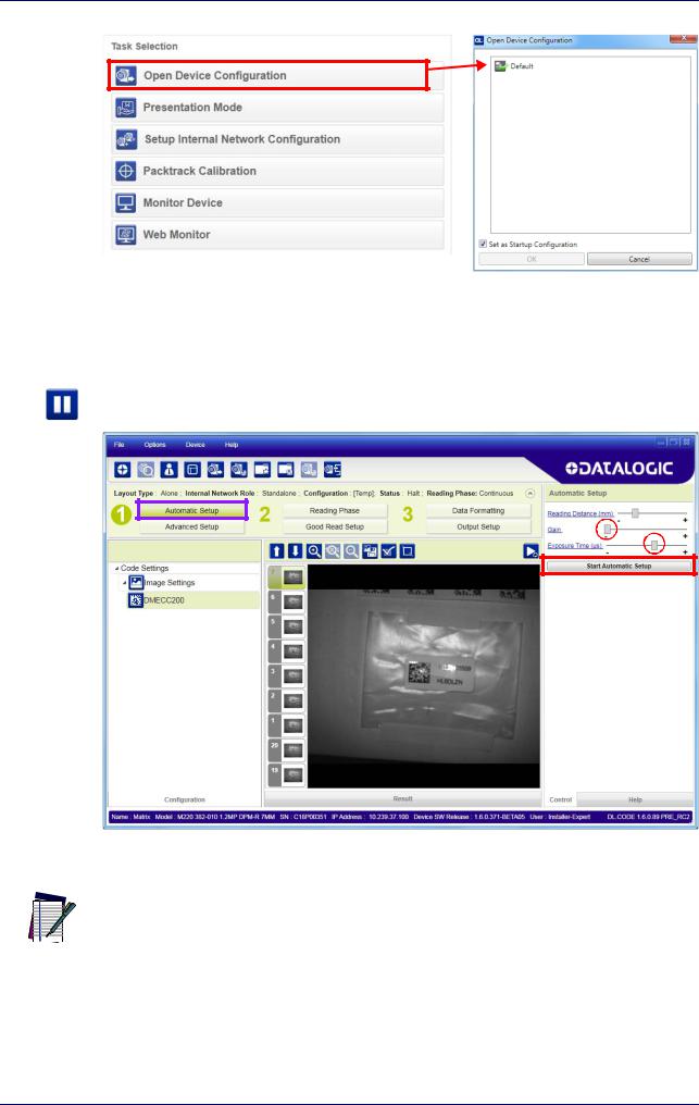
1.From the Task Area select Open Device Configuration.
2.The Open Device Configuration window opens showing the list of currently saved configurations (jobs) saved on the device. For new devices, the only saved job is the Default configuration. Click OK. The device enters run mode and begins acquiring images.
12 |
Matrix 220 |
Step 6 - Device Configuration
3.Place the application code in front of the reader at the correct application reading distance.
4. Click on the Pause button to stop image acquisition.
If the image display area is too dark to see the images being captured, you can drag
the Gain and Exposure Time sliders (circled in red in the figure above) to the right to
 increase visibility. This will not affect Automatic Setup. NOTE
5.Click on the Start Automatic Setup button. The following window is displayed:
Product Reference Guide |
13 |
Rapid Configuration
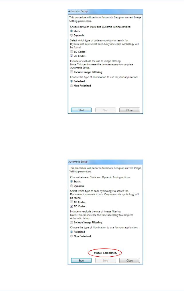
6.Select the correct reading conditions: Static or Dynamic Tuning, 1D or 2D code, Include Image Filtering (to find the best decoding condition). For DPM models you can select to use the Polarized or Non Polarized Illuminators.
7.Click Start to begin the procedure. The reader begins acquiring images. At the end of the procedure the Status: Completed message appears. You can Close the Automatic Setup window.
14 |
Matrix 220 |
 Loading...