


 Loading...
Arex™ 400
Laser Marker
User’s Manual
Datalogic S.r.l.
Via S. Vitalino, 13
40012 Calderara di Reno — Italy
Tel. +39 051 3147011
Fax +39 051 3147205
Arex™ 400 User’s Manual
Original Instructions
Ed.: 06/2019
This manual refers to Lighter™ Suite version 7.1.0 and later.
© 2018-2019 Datalogic S.p.A. and/or its affiliates
ALL RIGHTS RESERVED. Without limiting the rights under copyright, no part of this documentation may be reproduced, stored in or introduced into a retrieval system, or transmitted in any form or by any means, or for any purpose, without the express written permission of Datalogic S.p.A. and/or its affiliates.
Datalogic and the Datalogic logo are registered trademarks of Datalogic S.p.A. in many countries, including the U.S.A. and the E.U.
Arex™ 400, Arex™, Lighter™ Suite, Marvis™ and Matrix™ are trademarks of Datalogic S.p.A.and/or its affiliates. All other trademarks and bands are property of their respective owners.
Datalogic shall not be liable for technical or editorial errors or omissions contained herein, nor for incidental or consequential damages resulting from the use of this material.

|
Table of Contents |
PREFACE .............................................................................................................................................................................. |
VII |
Conventions ................................................................................................................................................................................... |
viii |
General ........................................................................................................................................................................................... |
viii |
Model Description ............................................................................................................................................................................ |
ix |
PRO Version .............................................................................................................................................................................. |
ix |
BASIC Version ........................................................................................................................................................................... |
ix |
CE Compliance ................................................................................................................................................................................... |
x |
FCC Compliance ................................................................................................................................................................................. |
x |
EAC Compliance ................................................................................................................................................................................. |
x |
UL Compliance .................................................................................................................................................................................. |
xi |
Laser Standards .............................................................................................................................................................................. |
xii |
Overview .......................................................................................................................................................................................... |
xiii |
Laser Source ........................................................................................................................................................................... |
xiii |
Galvanometric scan head ...................................................................................................................................................... |
xiii |
Operation of a laser marker with galvanometric scanning ............................................................................................... |
xiii |
Marking Software ................................................................................................................................................................... |
xiii |
Important Warnings .............................................................................................................................................................. |
xiv |
INSTALLATION ................................................................................................................... |
.................................................... 1 |
Unpacking ......................................................................................................................................................................................... |
2 |
Contents of the packaging .............................................................................................................................................................. |
4 |
On moisture condensation ............................................................................................................................................................. |
5 |
Note on moisture condensation ............................................................................................................................................. |
5 |
If moisture condensation occurs ............................................................................................................................................ |
5 |
How to avoid moisture condensation .................................................................................................................................... |
5 |
Fixing and positioning ..................................................................................................................................................................... |
6 |
Control Rack installation ................................................................................................................................................................. |
7 |
Horizontal installation ............................................................................................................................................................. |
7 |
Vertical installation .................................................................................................................................................................. |
9 |
Control rack mounting screws length .................................................................................................................................. |
10 |
Scan Head installation .................................................................................................................................................................. |
11 |
Scan head mounting screws length ..................................................................................................................................... |
14 |
Installation environment .............................................................................................................................................................. |
15 |
Control rack ............................................................................................................................................................................. |
15 |
Scan Head ............................................................................................................................................................................... |
16 |
Fume / Dust extractor ................................................................................................................................................................... |
17 |
TECHNICAL SPECIFICATIONS....................................................................................................... |
....................................... 18 |
Technical Characteristics .............................................................................................................................................................. |
19 |
Product Description ....................................................................................................................................................................... |
20 |
Control rack ............................................................................................................................................................................. |
20 |
Scan head ................................................................................................................................................................................ |
21 |
Marking Area Specification ........................................................................................................................................................... |
22 |
F-Theta Scan Lens for Arex™ 110-XXX, 120-XXX and A20-X6X ........................................................................................ |
22 |
F-Theta Scan Lens for Arex™ 130-X6X and 150-X6X ......................................................................................................... |
23 |
Green Spot ....................................................................................................................................................................................... |
24 |
Connectors Specifications ............................................................................................................................................................. |
25 |
Safety Circuit ........................................................................................................................................................................... |
25 |
Control rack back panel connector ............................................................................................................................... |
25 |
Muting Device ................................................................................................................................................................. |
27 |
Command Box (Laser Control) .............................................................................................................................................. |
28 |
User Manual |
iii |

Contents |
|
Control rack back panel connector ................................................................................................................................ |
28 |
Muting Device ................................................................................................................................................................. |
29 |
Axes (I/O Control) .................................................................................................................................................................... |
30 |
Control rack back panel connector ................................................................................................................................ |
30 |
Encoder .................................................................................................................................................................................... |
31 |
Control rack back panel connector ................................................................................................................................ |
31 |
Photocell .................................................................................................................................................................................. |
31 |
Control rack back panel connector ................................................................................................................................ |
31 |
Device Port 1 ........................................................................................................................................................................... |
32 |
Control rack back panel connector ................................................................................................................................ |
32 |
Device Port 2 ........................................................................................................................................................................... |
32 |
Control rack back panel connector ................................................................................................................................ |
32 |
RS232 (COM3) .......................................................................................................................................................................... |
33 |
Control rack back panel connector ................................................................................................................................ |
33 |
Ext Focus ................................................................................................................................................................................. |
33 |
Scan head connector ...................................................................................................................................................... |
33 |
Input/Output specifications .......................................................................................................................................................... |
34 |
Digital Input ............................................................................................................................................................................. |
34 |
Digital Output .......................................................................................................................................................................... |
34 |
Laser Marker States ....................................................................................................................................................................... |
35 |
Normal Operation States ....................................................................................................................................................... |
35 |
Error States ............................................................................................................................................................................. |
35 |
Warning State ......................................................................................................................................................................... |
35 |
Control the Laser Marker States ........................................................................................................................................... |
36 |
Key Selector mode .......................................................................................................................................................... |
36 |
Command Box mode ...................................................................................................................................................... |
36 |
Timing Diagrams ............................................................................................................................................................................. |
37 |
Turning On sequence .............................................................................................................................................................. |
37 |
Marking control signals behavior .......................................................................................................................................... |
37 |
SW_Ready output signal (Ready to Mark mode) ................................................................................................................. |
38 |
Good\Bad output signal ........................................................................................................................................................ |
38 |
System_Alarm output signal ................................................................................................................................................. |
38 |
MARVIS™ I/O signals behavior .............................................................................................................................................. |
39 |
Safety functions behavior ...................................................................................................................................................... |
39 |
Interlock behavior ........................................................................................................................................................... |
39 |
Laser_Stop behavior ....................................................................................................................................................... |
39 |
Green Spot behavior ............................................................................................................................................................... |
40 |
System Ready to Mark mode ........................................................................................................................................ |
40 |
Marking Confirmation mode ......................................................................................................................................... |
40 |
MARVIS Verification mode ............................................................................................................................................. |
40 |
Axes I/O signals behavior ...................................................................................................................................................... |
41 |
Lighter™ Suite marking software .................................................................................................................................................. |
42 |
INSTALLATION AND SET UP............................................................................................................................................... |
44 |
Connections ..................................................................................................................................................................................... |
45 |
Connecting Command Box connector .................................................................................................................................. |
45 |
Connecting Safety Circuit connector ..................................................................................................................................... |
46 |
Connecting Power Supply cable ............................................................................................................................................ |
47 |
Connecting the Earth Ground ................................................................................................................................................ |
47 |
Local Mode Control connections ........................................................................................................................................... |
48 |
Remote Mode Control connection ........................................................................................................................................ |
49 |
F-Theta scan lens protection cap removal .................................................................................................................................. |
49 |
USE AND OPERATION......................................................................................................................................................... |
50 |
First time boot ................................................................................................................................................................................. |
51 |
Turning On sequence ...................................................................................................................................................................... |
52 |
Sequence using Key Selector ................................................................................................................................................. |
52 |
Sequence Using Command Box ............................................................................................................................................. |
55 |
CUSTOMIZE THE LASER MARKER SOFTWARE ................................................................................................................ |
56 |
Change O.S. language and keyboard layout ................................................................................................................................ |
57 |
Change the LAN configuration and IP address ........................................................................................................................... |
60 |
Change the video setting ............................................................................................................................................................... |
63 |
iv |
Arex™ 400 |

|
Contents |
Remote desktop connection ......................................................................................................................................................... |
65 |
ACCESSORIES....................................................................................................................................................................... |
66 |
Control Box ...................................................................................................................................................................................... |
67 |
Remote Start Foot Switch ............................................................................................................................................................. |
67 |
I/O interface ................................................................................................................................................................................... |
68 |
DB25-to-Free Leads Cable ............................................................................................................................................................ |
68 |
MARVIS™ Add-on ............................................................................................................................................................................ |
69 |
MARVIS™ Mounting Bracket ................................................................................................................................................. |
69 |
MARVIS™ LED Ring Light ID 50mm - White ........................................................................................................................ |
69 |
Micrometric distance sensor kit ................................................................................................................................................... |
70 |
M39 F-Theta protective cap .......................................................................................................................................................... |
70 |
Starter Kit for Marking On the Fly (MOF) ..................................................................................................................................... |
71 |
Rack Handles .................................................................................................................................................................................. |
71 |
Fume Extractor ............................................................................................................................................................................... |
71 |
TECHNICAL SUPPORT ......................................................................................................................................................... |
72 |
Seals ................................................................................................................................................................................................ |
73 |
Maintenance ................................................................................................................................................................................... |
74 |
F-Theta scan lens cleaning procedure ................................................................................................................................. |
74 |
Air filter cleaning procedure .................................................................................................................................................. |
75 |
Troubleshooting ............................................................................................................................................................................. |
76 |
Service Interface ..................................................................................................................................................................... |
76 |
List of warning and error states ........................................................................................................................................... |
77 |
List of problems related to laser marker states ................................................................................................................. |
77 |
List of most common problems ........................................................................................................................................... |
78 |
Remote Assistance ........................................................................................................................................................................ |
79 |
Product Support and Customer Service ....................................................................................................................................... |
79 |
LABELS ............................................................................................................................................................. |
80 |
Labels .............................................................................................................................................................................................. |
81 |
Positioning of external labels ....................................................................................................................................................... |
82 |
Positioning of labels on the control rack: ............................................................................................................................ |
82 |
Positioning of labels on the scan head: ............................................................................................................................... |
82 |
Safety labels in local languages ................................................................................................................................................... |
83 |
UNDERSTANDING SLO: SAFE LASER OFF .............................................................................................. |
....... 84 |
Machine Safety ............................................................................................................................................................................... |
85 |
Risk Assessment ............................................................................................................................................................................ |
86 |
Performance Level (PL) .................................................................................................................................................................. |
87 |
Datalogic Laser Markers ............................................................................................................................................................... |
87 |
SLO connection diagram ............................................................................................................................................................... |
88 |
Safety Functions Of Arex™ 400 ..................................................................................................................................................... |
89 |
Arex™ XXX-X5X ....................................................................................................................................................................... |
89 |
Arex™ XXX-X6X ....................................................................................................................................................................... |
89 |
Example 1 ................................................................................................................................................................................ |
90 |
Example 2 ................................................................................................................................................................................ |
91 |
Example 3 ................................................................................................................................................................................ |
92 |
LASER SAFETY ................................................................................................................................................. |
93 |
Laser radiation ............................................................................................................................................................................... |
95 |
Absorption of laser radiation ........................................................................................................................................................ |
96 |
Classification and danger level .................................................................................................................................................... |
97 |
Degree of risk with radiation viewing conditions ...................................................................................................................... |
97 |
Direct viewing of the laser beam .......................................................................................................................................... |
97 |
Viewing of a laser reflected beam ........................................................................................................................................ |
98 |
Viewing of direct laser beam from a fiber output .............................................................................................................. |
98 |
Viewing of scattered laser beam .......................................................................................................................................... |
98 |
N.O.H.D. determination and O.D. of protection goggles ............................................................................................................ |
99 |
Accidental vision of the reflected laser radiation ............................................................................................................. |
100 |
Filter scale index of the protection goggles ...................................................................................................................... |
100 |
Eyes and skin risks ...................................................................................................................................................................... |
100 |
General safety regulations .......................................................................................................................................................... |
100 |
Other risks .................................................................................................................................................................................... |
101 |
User Manual |
v |

Contents |
|
USING MARKING SOFTWARE ....................................................................................................................... |
102 |
How to create and edit graphics layout .................................................................................................................................... |
103 |
How to test and mark layout ...................................................................................................................................................... |
106 |
How to use Command Box signals to mark layout .................................................................................................................. |
108 |
MOPA FIBER LASER ...................................................................................................................................... |
110 |
Laser marker operations ............................................................................................................................................................. |
111 |
Pulse Profile ......................................................................................................................................................................... |
113 |
Lighter™ Pulse Profile Configuration ......................................................................................................................................... |
115 |
Creating a document with multiple objects using a single pulse profile ...................................................................... |
115 |
Creating a document with multiple objects using different pulse profiles ................................................................... |
116 |
MARKING SOFTWARE UPGRADE ................................................................................................................. |
118 |
How to update the marking software ....................................................................................................................................... |
119 |
RECOVER THE LASER MARKER.................................................................................................................... |
124 |
Overview ....................................................................................................................................................................................... |
125 |
How to recover the laser marker ............................................................................................................................................... |
125 |
Recover the system: ............................................................................................................................................................ |
125 |
Initialize the Hardware ........................................................................................................................................................ |
128 |
Customize the marking software ...................................................................................................................................... |
129 |
MECHANICAL DRAWINGS ............................................................................................................................. |
130 |
Control Rack ................................................................................................................................................................................. |
131 |
Scan Head ..................................................................................................................................................................................... |
132 |
vi |
Arex™ 400 |

Preface
CONVENTIONS starting on page viii
GENERAL starting on page viii
MODEL DESCRIPTION starting on page ix
CE COMPLIANCE starting on page x
FCC COMPLIANCE starting on page x
EAC COMPLIANCE starting on page x
UL COMPLIANCE starting on page xi
LASER STANDARDS starting on page xii
OVERVIEW starting on page xiii
User Manual |
vii |
Preface
Conventions
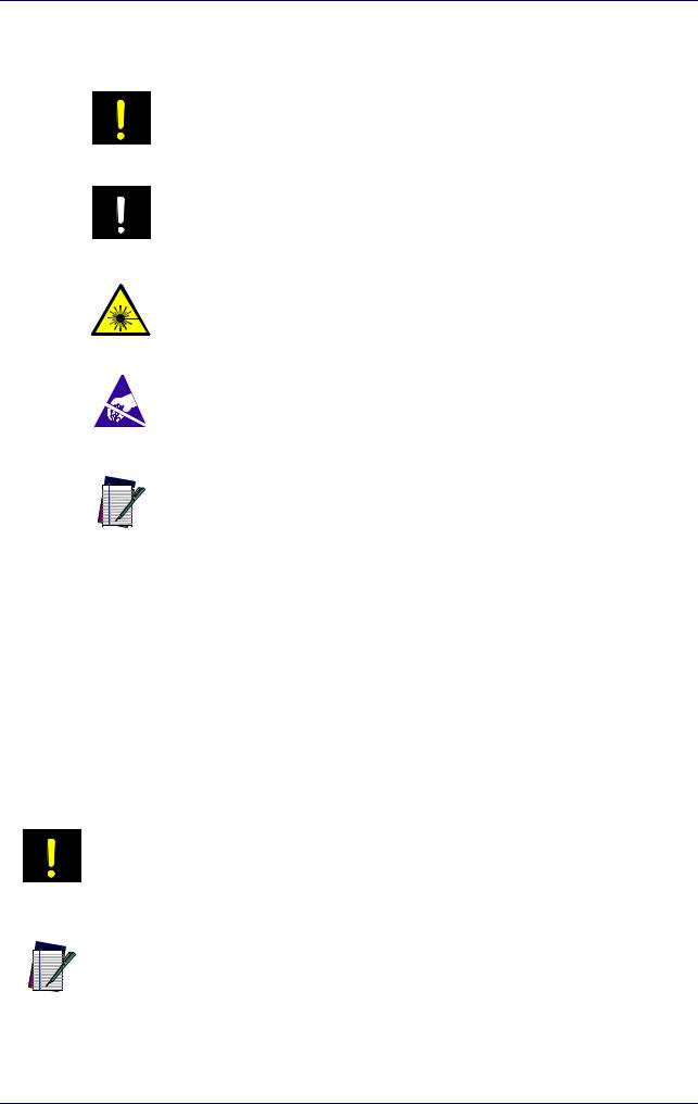
Warnings
High Voltage
Laser Caution
This symbol identifies a hazard or procedure that, if incorrectly performed, could cause personal injury or result in equipment damage. It is also used to bring the user’s attention to details that are considered IMPORTANT.
This symbol alerts the user they are about to perform an action involving, either a dangerous level of voltage, or to warn against an action that could result in damage to devices or electrical shock.
This symbol alerts the user they are about to perform an action involving possible exposure to laser light radiation.
ESD
Notes
This symbol identifies a procedure that requires you take measures to prevent Electrostatic Discharge (ESD) e.g., use an ESD wrist strap. Circuit boards are most at risk. Please follow ESD procedures.
This symbol draws attention to details or procedures that may be useful in improving, maintaining, or enhancing the performance of the hardware or software being discussed.
General
Information included in this manual is intended for a qualified installer able to integrate the laser marker into a system, complying with all the protection features required by international rules and local legislations. Refer to the following sections for further information.
This manual refers to Arex™ 400 Fiber laser markers, that is a Class 4 Laser Product.
In addition to being professionally trained in their role, personnel assigned to work with laser marker must be informed and made acquainted with the risks inherent to invisible and visible laser radiation. The operator is required to carefully read the section of the manual concerning safety instructions as well as the sections related to matters falling under her/his responsibility.
Datalogic shall not be held responsible for any non-conforming use of laser marker of its manufacture.
WARNING
BEFORE INSTALLING AND USING THE LASER, CAREFULLY READ THIS MANUAL.
NOTE
viii |
Arex™ 400 |
Model Description
Model Description
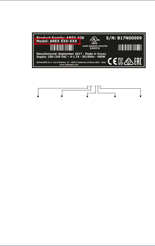
Arex™ 400 laser markers are described by their model number which indicates the characteristics listed in the diagram below. Not all combinations are available. For a complete list of combinations see the Models tab on the Product page of the website.
AREX XXX-XXX
Laser Type |
Power |
F-Theta scan lens |
Version |
Operating System |
1 = Pulsed Fiber |
10 = 10W |
3 = 160 S |
5 = BASIC |
4= Windows® 7 |
A = Fiber MOPA |
20 = 20W |
4 = 160L |
6 = PRO |
|
|
30 = 30W |
6 = 254 S |
|
|
|
50 = 50W |
7 = 254 L |
|
|
|
|
9 = 100 L |
|
|
|
|
A = 330 L |
|
|
|
|
B = 420 L |
|
|
PRO Version
•Wider power range selection
•Wider F-Theta scan lens selection
•High performance level for safety features
•High PC performance (powered by Intel® Celeron®)
•3x Ethernet ports 10/100/1000 Mbps
•High Precision Marking Field Center specifications
•Advanced software features
BASIC Version
•Models with power level 10W & 20W
•Basic performance level for safety features
•Basic PC performance (powered by Intel® Atom®)
•1x Ethernet port 10/100/1000 Mbps
•Basic Precision Marking Field Center specifications
•Basic software features
User Manual |
ix |

Preface
CE Compliance
CE marking states the compliance of the product with essential requirements listed in the applicable European directive. Since the directives and applicable standards are subject to continuous updates, and since Datalogic promptly adopts these updates, therefore the EU declaration of conformity is a living document. The EU declaration of conformity is available for competent authorities and customers through Datalogic commercial reference contacts. Since April 20th, 2016 the main European directives applicable to Datalogic products require inclusion of an adequate analysis and assessment of the risk(s). This evaluation was carried out in relation to the applicable points of the standards listed in the Declaration of Conformity. Datalogic products are mainly designed for integration purposes into more complex systems. For this reason it is under the responsibility of the customer to do a new risk assessment regarding the final installation.
This is a Class A product. In a domestic environment this product may cause radio interference in which case the user may be required to take adequate measures.
WARNING
FCC Compliance
Modifications or changes to this equipment without the expressed written approval of Datalogic could void the permission to use the equipment.
This laser marker complies with PART 15 of the FCC Rules. Operation is subject to the following two conditions: (1) this laser marker may not cause harmful interference, and (2) this laser marker must accept any interference received, including interference which may cause undesired operation.
This laser marker has been tested and found to comply with the limits for a Class A digital device, pursuant to part 15 of the FCC Rules. These limits are designed to provide reasonable protection against harmful interference when the equipment is operated in a commercial environment. This laser marker generates, uses, and can radiate radio frequency energy and, if not installed and used in accordance with the instruction manual, may cause harmful interference to radio communications. Operation of this laser marker in a residential area is likely to cause harmful interference in which case the user will be required to correct the interference at his/her own expense.
EAC Compliance
Customs Union: this laser marker complies with CU Conformity certification; this allows the Product to bear the Eurasian Mark of conformity.
x |
Arex™ 400 |
UL Compliance
UL Compliance
Reading this manual prevents the operator from carrying out operations that could cause damage to himself or others.
Follow-Up Service Procedure issued on 2019-03-26.
User Manual |
xi |

Preface
Laser Standards
This laser marker is classified as Class 4 Laser Product according to the following:
EU: EN60825-1
USA: 21 CFR 1040.10 China: GB7247-1
Datalogic, as manufacturer of laser products, provides a laser marker which is NOT intended for immediate use, but it must be connected, by others, to other devices which have the final aim of creating a laser processing system.
The final system manufacturer MUST ensure the safety of the laser processing machine according to its standards including the risk-analysis, implementation of safety measures, certification and testing of safety measures and the production of adequate information for use of the machine.
Datalogic is available for providing to the customers all the information in its possession to help in complying with applicable standards.
Use of controls or adjustments or performance of procedures other than those specified herein may result in hazardous radiation exposure.
CAUTION
xii |
Arex™ 400 |

Overview
Overview
The Fiber laser marker developed and manufactured by Datalogic employs the most advanced technologies with regards to the opto-mechanical parts, the electronic control of laser beam power, communication and the overall safety of the entire marker.
The Arex™ 400 laser marker features a control rack and a scan head. The control rack size is standard 19" 2.5U. The scan head compact dimensions make it easy to integrate.
All product connections are on the rear or front of the control rack.
Laser Source
On Arex™ 400 laser marker it is used a sealed fiber laser source. This source is based on the new fiber solid state technology. It guaranties high stability, lower sensitivity to optical misalignment and a longer product lifetime.
Galvanometric scan head
The scan head features two deflection mirrors that deflect the beam in X and Y directions, depending on the graphics/pattern to be reproduced.
Operation of a laser marker with galvanometric scanning
During the marking the laser generates an invisible, high-energy infrared beam.
In order to obtain a more accurate focus, the laser beam is first enlarged using an optical expansion system and then deflected by a scanning system consisting of two mirrors mounted on galvanometric motors.
These mirrors deflect the beam in a controlled path along the X and Y axes; processing of the product surface occurs by coordinating the movement of the two mirrors and the turning on/off of the laser beam.
The deflected laser beam is focused by an F-Theta scan lens on the surface of the product.
Generally speaking, the marking is carried out within the focus plane of the F- Theta scan lens.
Marking Software
The Ligther™ marking software is preinstalled on the product.
Consult Lighter™ software user's manual for a proper use of the same.
NOTE
If necessary, consult “How to update the marking software” on page 97, to upgrade the preinstalled software.
NOTE
User Manual |
xiii |
Preface
Important Warnings
Access to the internal parts of the laser marker is allowed only to authorized personnel, duly qualified and trained with regards to risks of optical and electrical nature.
Datalogic declines any and all responsibility for work carried out on active parts by untrained or unauthorized personnel.
It is forbidden to change the intended use for which the product was designed and developed.
Datalogic declines any and all responsibility for improper use of its laser product.
WARNING
The integration and use of this laser marker is customer responsibility.
WARNING
Never expose reflecting surfaces to laser radiation!
The reflected laser beam may cause damage to laser marker.
WARNING
Laser marking interacts with materials through, for example, a thermal carbonization process which may lead to the emission of fumes, dust and vapors.
Adequate fume/dust extractor and treatment must be provided by customer!
WARNING
Marking PVC (or other plastic material) can cause the release of chlorine gas which can be harmful to the laser operator and to the laser marker itself. Always use adequate
fume extractor during PVC and plastic marking.
WARNING
It is the responsibility of the customer to install the laser marker in proper safety condition!
WARNING
xiv |
Arex™ 400 |

Chapter 1
Installation
UNPACKING starting on page 2
CONTENTS OF THE PACKAGING starting on page 4
ON MOISTURE CONDENSATION starting on page 5
FIXING AND POSITIONING starting on page 6
CONTROL RACK INSTALLATION starting on page 7
SCAN HEAD INSTALLATION starting on page 11
INSTALLATION ENVIRONMENT starting on page 15
FUME / DUST EXTRACTOR starting on page 17
User Manual |
1 |

Installation
Unpacking
Control rack and scan head are joined by a connection cable 3 meters long, referred as Head Cable. Control rack and scan head are NOT separable.
WARNING
Be extremely careful to not damage the connection cable between scan head and control rack.
WARNING
To avoid damaging or breaking the optical fiber, never subject the Head Cable to a bending radius below the limits specified in the technical specification table (see
“Technical Characteristics” on page 19).
WARNING
The Arex™ 400 laser marker is a delicate optical device, that can be damage by shock and vibrations.
WARNING
2 |
Arex™ 400 |
Unpacking
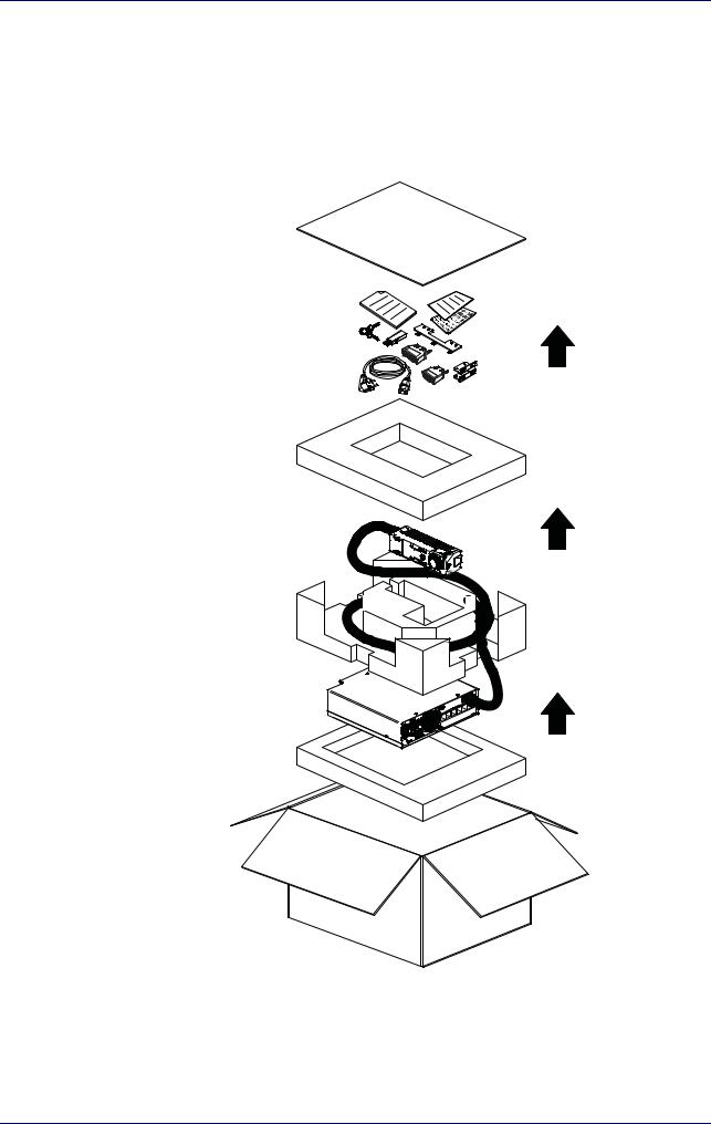
Before installing or operating the laser marker, you should:
-Inspect the shipping container for damage
-Inspect the laser marker for signs of damage
-Confirm that the shipping box contains all items on the shipping inventory list including any accessories
When unpacking the laser marker from the shipping box you should:
-Remove the accessories and documentations
-Carefully remove the laser marker from the packaging using both hands
Figure 1: Unpacking
Keep all packing materials until the laser has been inspected for completeness and damage. If something is missing or defective, call Datalogic (see “Product Support and Customer Service” on page 79 for contact details).
User Manual |
3 |

Installation
Contents of the packaging
|
|
3x |
Control Rack |
Scan Head |
Power Supply cables |
|
|
|
|
|
|
|
|
|
|
|
|
|
|
|
|
|
|
|
|
|
|
|
|
|
|
|
|
|
|
|
|
|
|
|
|
|
|
|
|
|
|
|
|
|
Rack Fixing Brackets |
Command Box |
Safety Circuit |
||||||
(Only for XXX-X6X models) |
MUTING DEVICE |
MUTING DEVICE |
||||||
|
|
|
|
|
|
|
|
|
|
|
|
|
|
|
|
|
|
|
|
|
|
|
|
|
|
|
|
|
|
|
|
|
|
|
|
|
|
|
|
|
|
|
|
|
|
|
|
|
|
|
|
|
|
|
|
|
|
|
|
|
|
|
|
|
|
|
|
|
|
|
|
|
|
|
|
|
|
|
|
|
|
|
|
|
|
|
|
|
|
|
|
|
|
|
|
|
|
|
|
|
|
|
|
|
|
|
|
|
|
|
|
|
|
|
|
|
|
|
|
|
|
|
|
|
|
|
|
|
|
|
|
|
|
|
|
|
|
|
|
|
|
|
|
|
|
|
|
|
|
|
|
|
|
|
|
|
|
|
|
|
|
|
|
|
|
|
|
|
|
|
|
|
|
|
|
|
|
|
|
|
|
|
|
|
|
|
|
|
|
|
|
|
Safety labels |
|
|
|
|
USB Recovery Disk |
|
|
|
Selector Keys |
||||||||||||||
|
|
|
|
|
|
|
|
|
|
|
|
|
|
|
|
|
|
|
|
|
|
|
|
|
|
|
|
|
|
|
|
|
|
|
|
|
|
|
|
|
|
|
|
|
|
|
|
|
|
|
|
|
|
|
|
|
|
|
|
|
|
|
|
|
|
|
|
|
|
|
|
|
|
|
|
|
|
|
|
|
|
|
|
|
|
|
|
|
|
|
|
|
|
|
|
|
|
|
|
|
|
|
|
|
|
|
|
|
|
|
|
|
|
|
|
|
|
|
|
|
|
|
|
|
|
|
|
|
|
|
|
|
|
|
|
|
|
|
|
|
|
|
|
|
|
|
|
|
|
|
|
|
|
|
|
|
|
|
|
|
|
|
|
|
|
|
|
|
|
|
|
|
|
|
|
|
|
|
|
|
|
|
|
|
|
|
|
|
|
|
|
|
|
|
|
|
|
|
|
|
|
|
|
|
|
|
|
|
|
|
|
|
|
|
|
|
|
|
|
|
|
|
|
|
|
|
|
|
|
|
|
|
|
|
|
|
|
|
|
|
|
|
|
|
|
|
|
|
|
|
|
|
|
|
|
|
|
|
|
|
|
|
|
|
|
|
|
|
|
|
|
|
|
|
|
|
|
|
|
|
|
|
|
|
|
VGA to DVI Adapter |
Test report and sample test |
Scan Head Fixing Bracket |
plate |
(Only for XXX-X6X models) |
Quick Reference Guide
4 |
Arex™ 400 |

On moisture condensation
On moisture condensation
If the laser marker is brought directly from a cold to a warm location, moisture may condense inside or outside the laser product. This moisture condensation may cause a malfunction of the laser marker.
Note on moisture condensation
Moisture may condense when you bring the laser marker from a cold place into a warm place (or vice versa) and when you use the laser marker in a humid place.
If moisture condensation occurs
Turn off the laser marker and wait about 1 hour for the moisture to evaporate.
How to avoid moisture condensation
Before moving the laser marker from a cold place into a warm place, put it in a plastic bag and seal it tightly. Remove the bag when the air temperature inside the plastic bag has reached the ambient temperature (after about 1 hour).
User Manual |
5 |

Installation
Fixing and positioning
WARNING
WARNING
WARNING
NOTE
NOTE
Fix the laser marker according to instructions shown in the figures.
It is mandatory to secure the laser marker before you start marking, since improper securing or positioning may cause serious damage.
Do not secure the laser marker in a way other than the one described in the figure.
Introduction of optical or mechanical surfaces, such as mechanical shutters or additional protective glass, between F-Theta scan lens output and marking surface may case optical feedback into the laser marker.
Optical induced damage caused to laser marker by reflection from external surfaces is not covered by warranty.
In order to prevent marking distortions, avoid vibrations and bumps during the marking process!
It is recommended to install the scan head on a positioning Z-axis system for accurate mounting at focal distance!
6 |
Arex™ 400 |
Control Rack installation
Control Rack installation
Horizontal installation
The control rack must be positioned in a safe manner, following the recommendations below:
Figure 2: Control rack horizontal positioning
The control rack can be installed on a standard 19" rack cabinet using the fixing brackets supplied as a standard equipment with XXX-X6X models and as an accessory for XXX-X5X models (see "Rack Handles" on page 71).
The figure below shows the fixing points for installation in a rack cabinet. Rack handles for an easier installation are available as an accessory (see "Rack Handles" on page 71).
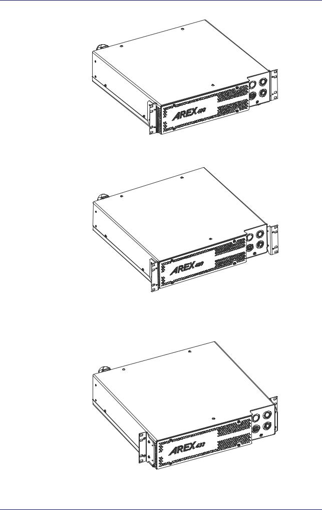
Using the fixing brackets is possible to install the control rack in three different positions inside the cabinet:
Figure 3: Control rack fixing bracket mounting configuration
All dimensions are in millimeters.
NOTE
User Manual |
7 |
Installation
Using this position the fixing brackets are aligned with the console.
Figure 4: Control rack fixing brackets mounting position 1
Using this position the fixing brackets are aligned with the frontal grid panel.
Figure 5: Control rack fixing brackets mounting position 2
Use this position if you want to use a pre-existing integration for AREX™ 3 and it is required that the back panel of AREX™ 400 is in the same position as the back panel of AREX™ 3 inside the cabinet.
Figure 6: Control rack fixing brackets mounting position 3
8 |
Arex™ 400 |
Control Rack installation
Vertical installation
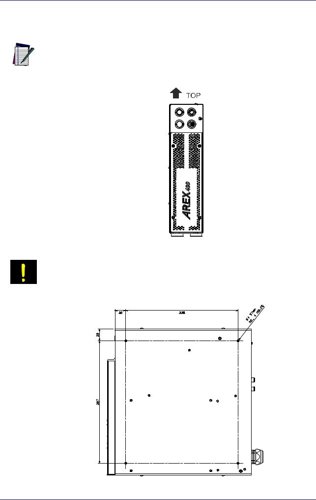
The control rack must be positioned in a safe manner, following the recommendations below.
The feet must be removed from the bottom of the control rack and installed on the left side of the control rack using the appropriate fixing points. Tightening torque = 0.5 Nm.
NOTE
Figure 7: Control rack vertical positioning
The control rack MUST be fixed to a side wall using the appropriate fixing points placed on the bottom of the control rack.
WARNING
Figure 8: Control rack fixing points for vertical installation
User Manual |
9 |

Installation
Control rack mounting screws length
To determine the length of the mounting screws, consider the thickness of the mounting plate and the thickness of the washer.
Control rack
7 mm
Mounting plate thickness |
Washer thickness |
M4 screw |
Figure 9: Length of mounting screws
Mounting holes depth is = 7mm. Tightening torque = 2 Nm.
NOTE
10 |
Arex™ 400 |
Scan Head installation
Scan Head installation
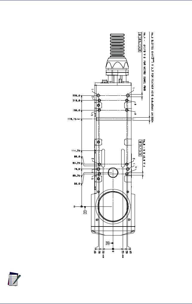
The scan head can be installed in any orientation and must be fixed to a suitable base (not supplied by Datalogic) using the dedicated threaded holes and the high precisions slotted seats:
Figure 10: Fixing points on scan head (bottom view)
All dimensions are in millimeters.
NOTE
User Manual |
11 |
Installation
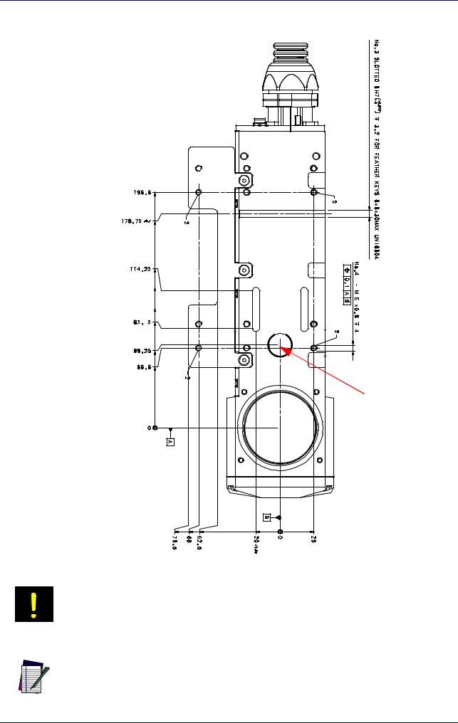
A fixing bracket for scan head is provided to offer dedicated threaded holes designed to be fully compatible with Arex™ 3 products:
Focusing Beam output |
Figure 11: Fixing points on scan head (back compatibility with Arex™ 3)
If the scan head is mounted on an existing support suitable for Arex™ 3, the Arex™ 400 focusing beam diode may be covered.
WARNING
All dimensions are in millimeters.
NOTE
12 |
Arex™ 400 |
Scan Head installation
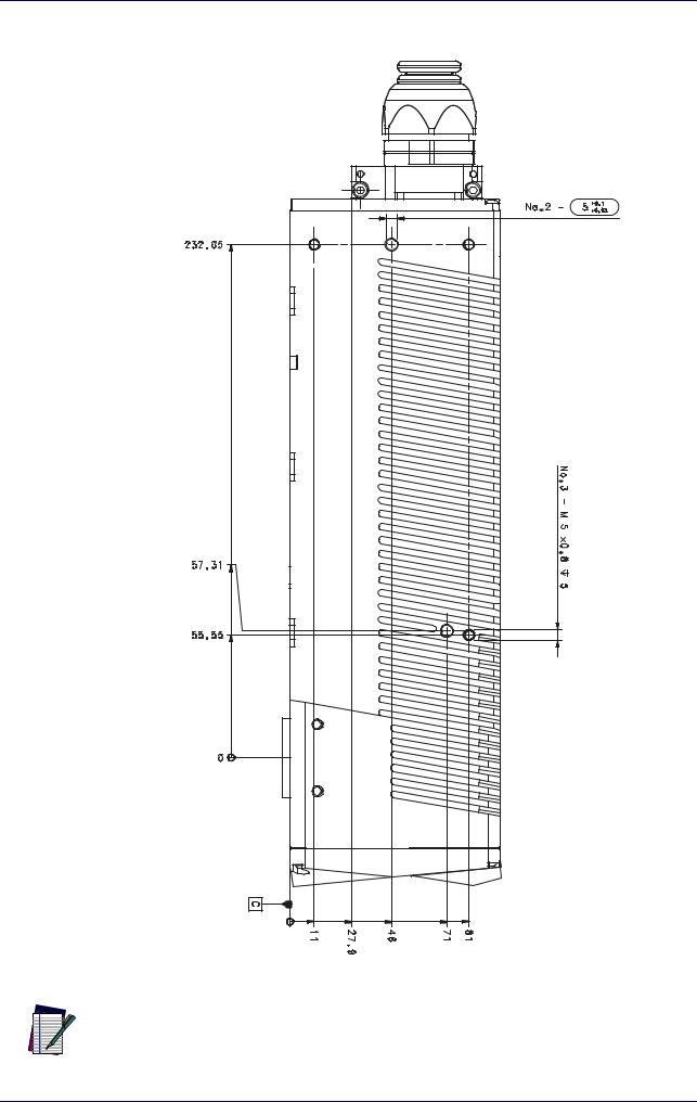
It is also possible to mount the scan head sideways using dedicated threaded holes:
Figure 12: Fixing points on scan head side
All dimensions are in millimeters.
NOTE
User Manual |
13 |
Installation
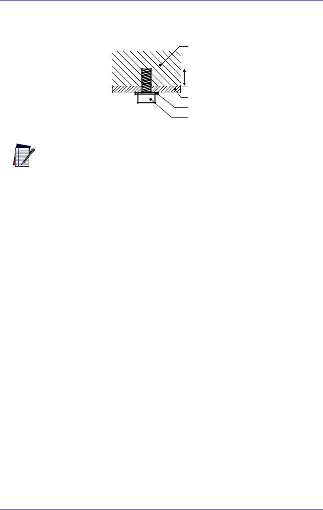
Scan head mounting screws length
To determine the length of the mounting screws, consider the thickness of the mounting plate and the thickness of the washer.
Scan Head
4 mm
Mounting plate thickness |
Washer thickness |
M5 screw |
Figure 13: Length of mounting screws
Mounting holes depth is = 4mm. Tightening torque = 2 Nm.
NOTE
14 |
Arex™ 400 |
Installation environment
Installation environment
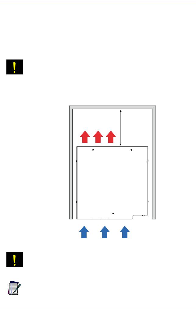
Control rack
The control rack must be installed in a suitable environment in order to allow proper air flow and correct housing of the cables.
The control rack uses a forced air cooling system: an adequate air flow is necessary to guarantee its correct cooling. Install the control rack so that air flow is not obstructed. Moreover, do not install it near a heat source.
If not enough space is provided, the temperature inside the control rack could rise, causing temperature error.
WARNING
Clean the air filter when it is dirty. If the air filter is dirty, insufficient air-flow might not ensure correct cooling and might stop the marking operation. Clean or replace the air filter periodically.
≥300mm |
Figure 14: Control rack installation environment
DO NOT place heavy objects on top of the control rack!
WARNING
The control rack IP rating is IP31 in horizontal position, otherwise IP30.
NOTE
User Manual |
15 |
Installation
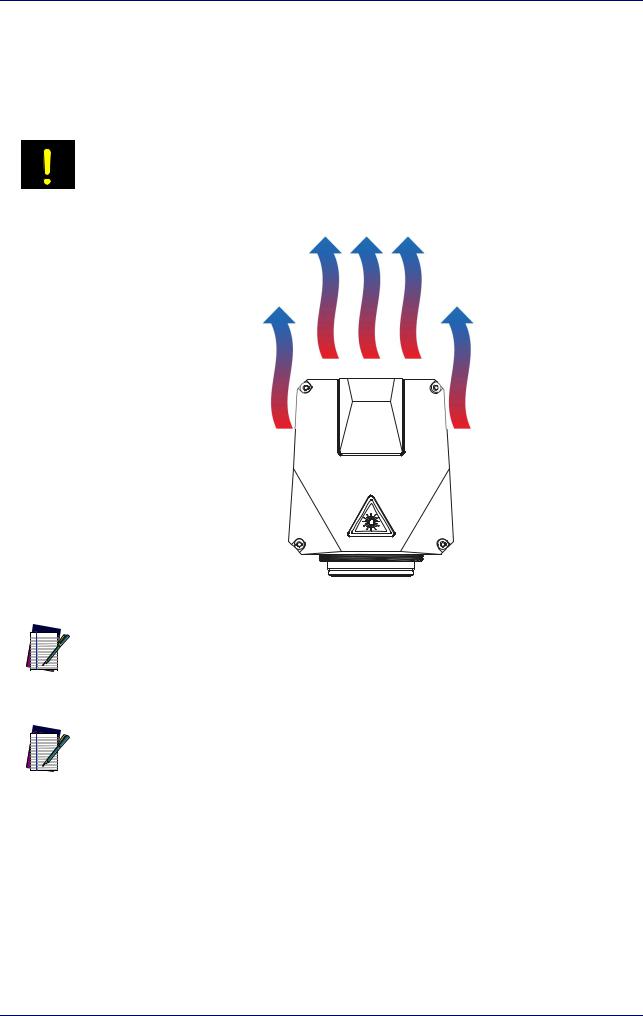
Scan Head
The scan head must be installed in a suitable environment in order to allow proper air flow and correct housing of the cables.
The scan head uses a passive air cooling system: an adequate air flow is necessary to guarantee its correct cooling. Install the scan head so that air flow is not obstructed. Moreover, do not install it near a heat source.
If not enough space is provided, the temperature inside the control rack could rise,
causing temperature error.
WARNING
Figure 15: Scan head installation environment
The scan head IP rating is IP64 not considering F-Theta scan lens.
NOTE
To ensure a complete IP64 protection for 160S and 254S F-Theta scan lenses use the proper accessory (see "M39 F-Theta protective cap" on page 70).
NOTE
16 |
Arex™ 400 |
Loading...