

Page 1
Interne
Ab
DNC
N°
EXT
I/O
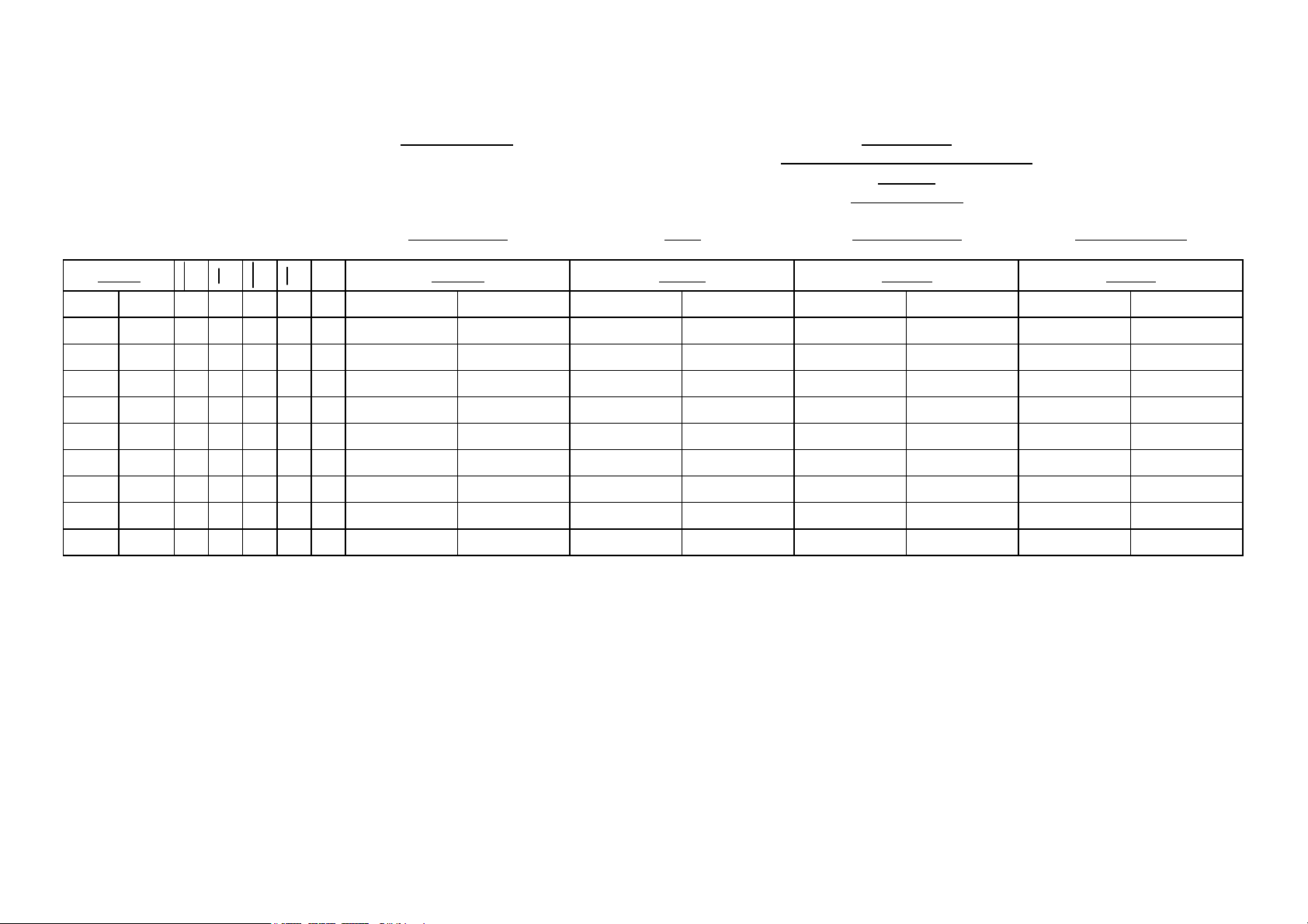
V-DNC-64-PS8
DNC 64 PS
Version de Base pour PS et PSS
8 I / 8 O
Y1 / Y2 + X / R
Descriptions Note Bemerkungen Descripciones
~
Français
English Deutsch Español
{
z
z
{
½
¾
1
2
1
Comme indiqué dans le chapitre "Précautions de raccordement" de la Notice technique, tous les câbles reliant la DNC à l'armoire doivent être blindés.
Le signe ~ indique que le blindage doit continuer jusqu'à la fiche et qu'il doit y être raccordé.
Si le signe ~ est absent, le blindage peut se terminer au niveau des brides de serrage et de mise à la masse.
1
As mentioned in the chapter "Connection Precautions" of the Technical Information manual, all cables connecting the DNC with the electrical cabinet must be shielded.
The ~ sign indicates that the shielding must continue up to the plug and must be connected to it.
When there is no ~ sign, the shielding can end at the level of the holding clamps and the mass clamps.
1
Wie im Kapitel "Vorsichtsmassnahmen für den Anschluss" der Technischen Beschreibung angegeben, müssen alle Kabel, welche die DNC mit dem elektrischen Schaltschrank verbindet,abgeschirmt sein.
Das Zeichen ~ gibt an, dass die Abschirmung bis zum Stecker geführt und mit diesem verbunden werden muss.
Ist kein Zeichen ~ vorhanden, so kann die Abschirmung auf der Höhe der Klemmhalterung und der Masseanschlusshalterung enden.
1
Como indicado en el capitulo "Conneción Precaucións" en la noticiá "Technical Information", todos los cables que reliàn la DNC al armario electrico tienén que ser blindados.
El signo ~ indica que el blindaje tiene que ír asta la ficha y estar empalmado.
Si este signo ~ no esta, el blindaje puede terminarse á la altura de las abrazaderas de apretadura y de masa de todos los cables ligando la DNC.
Prise femelle Socket female Buchse (DNC) Enchufe embra
Prise mâle Socket male Stift (DNC) Enchufe machos
Fiche mâle Plug male Stift (EXT) Enchufe machos
Fiche femelle Plug female Buchse (EXT) Enchufe embra
Entrée Input Eingang Entrada
Sortie Output Ausgang Salida
Contact 1 Pin 1 Schaltglied 1 Contacto 1
Contact 2 Pin 2 Schaltglied 2 Contacto 2
~
Câble blindé
1
Shielded cable
Capot blindé Shielded cover
1
geschirmtes
1
Abgeschirmte
Haube
Cable blindado
Capot blindado
1
LS60-PS-6i
LS60-PS-6.pdf
1 / 7 19.03.2004
Page 2
Interne
pply
g
(
)
(
)
(
)
(
)
(
)
(
)
(
)
(
)
pply
g
g
g
Interne
DCD
RxD
TxD
DTR
0V
DSR
RTS
CTS
RING
Interne
DNC
z
z
z
z
DNC
z
z
z
z
z
z
z
z
z
DNC
EXT
N°
1
2
3
4
N°
1
2
3
4
5
6
7
8
9
N°
I/O
{½
{½
{½
{½
EXT
I/O
{½~
{½~
{¾~
{¾~
{~
{½~
{¾~
{½~
{½~
EXT
I/O
MB6 J19
~
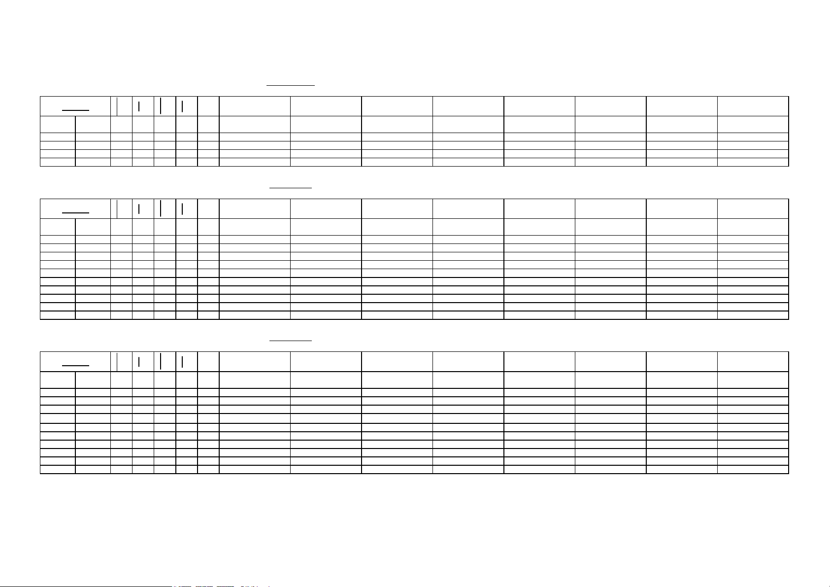
Alimentation Power supply Anspeisung Alimentación
4 contacts mâles WAGO 4 pins male WAGO 4 polig männlich WAGO 4 contactos machos WAGO
+24 VDC Alimentation +24 VDC Power su
0VDC
0VDC
+24 VDC Alimentation +24 VDC Power su
24 VDC
24 VDC
0VDC
0VDC
24 VDC
24 VDC
+24 VDC Anspeisun
0VDC
0VDC
+24 VDC Anspeisun
24 VDC
24 VDC
+24 VDC Alimentación
0VDC
0VDC
+24 VDC Alimentación
MB6 J5
~
COM 1 RS232 COM 1 RS232 COM 1 RS232 COM 1 RS232
9 contacts mâles SUB-D 9 pins male SUB-D 9 polig männlich SUB-D 9 contactos machos SUB-D
DCD DCD DCD DCD
RxD RxD RxD RxD
TxD TxD TxD TxD
DTR DTR DTR DTR
0V 0V 0V 0V
DSR DSR DSR DSR
RTS RTS RTS RTS
CTS CTS CTS CTS
RING RING RING RING
e Blindage Shield Shield Schirm Schirm Blindaje Blindaje
Blinda
MB6 J6
~
COM 2 RS232 COM 2 RS232 COM 2 RS232 COM 2 RS232
24 VDC
24 VDC
9 contacts mâles SUB-D 9 pins male SUB-D 9 polig männlich SUB-D 9 contactos machos SUB-D
DCD
RxD
TxD
DTR
0V
DSR
RTS
CTS
RING
LS60-PS-6i
LS60-PS-6.pdf
z
z
z
z
z
z
z
z
z
{½~
1
{½~
2
{¾~
3
{¾~
4
{~
5
{½~
6
{¾~
7
{½~
8
{½~
9
DCD DCD DCD DCD
RxD RxD RxD RxD
TxD TxD TxD TxD
DTR DTR DTR DTR
0V 0V 0V 0V
DSR DSR DSR DSR
RTS RTS RTS RTS
CTS CTS CTS CTS
RING RING RING RING
e Blindage Shield Shield Schirm Schirm Blindaje Blindaje
Blinda
2 / 7 19.03.2004
Page 3
Interne
giq
p
p
(
)
(
)
(
)
(
)
(
)
(
)
(
)
(
)
g
giq
g
p
g
g
p
(
)
(
)
(
)
(
)
(
)
(
)
(
)
(
)
g
giq
g
g
g
g
g
g
g
PANI2
PANI1
AGND
+10VR
AGND
+10VR
Interne
PANI4
PANI3
AGND
+10VR
AGND
+10VR
Interne
U AUX Y1
U AUX Y2
AGND
U AUX 0
U AUX 1
AGND
AGND
AGND
AGND
DNC
{
{
{
{
{
{
DNC
{
{
{
{
{
{
DNC
z
z
z
z
z
z
z
z
z
EXT
N°
z½~
1
z½~
2
z¾~
3
z¾~
4
z¾~
5
z¾~
6
EXT
N°
z½~
1
z½~
2
z¾~
3
z¾~
4
z¾~
5
z¾~
6
EXT
N°
{¾~
1
{¾~
2
{¾~
3
{¾~
4
{¾~
5
{¾~
6
{¾~
7
{¾~
8
{¾~
9
I/O
I/O
I/O
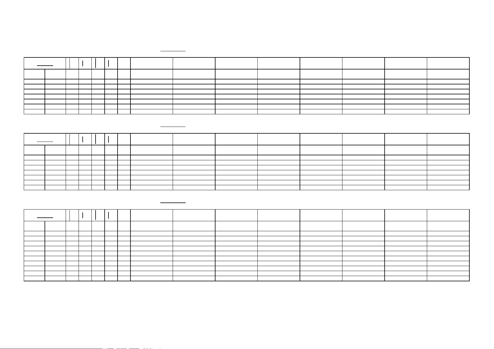
MB6 J7
Entrées
~
analo
6 contacts femelles mini-DIN 6 pins female mini-DIN 6 polig weiblich mini-DIN 6 contactos embra mini-DIN
Entrée 2 FA2 In
Entrée 1 FA1 In
0V 0V 0V 0V
+10V Réf.
0V 0V 0V 0V
+10V Réf.
Blinda
ues
max. 10mA
max. 10mA
e Blindage Shield Shield Schirm Schirm Blindaje Blindaje
Analog Inputs Analog Eingänge
ut 2 FA2 Eingang 2 FA2 Entredas 2 FA2
ut 1 FA1 Eingang 1 FA1 Entredas 1 FA1
+10V Réf.
+10V Réf.
max. 10mA
max. 10mA
+10V Réf.
+10V Réf.
max. 10mA
max. 10mA
Entredas
analógicas
+10V Réf.
+10V Réf.
MB6 J8
Entrées
~
analo
6 contacts femelles mini-DIN 6 pins female mini-DIN 6 polig weiblich mini-DIN 6 contactos embra mini-DIN
Entrée 4 Bomba
Entrée 3 In
0V 0V 0V 0V
+10V Réf.
0V 0V 0V 0V
+10V Réf.
Blinda
ues
eIn
max. 10mA
max. 10mA
e Blindage Shield Shield Schirm Schirm Blindaje Blindaje
Analog Inputs Analog Eingänge
ut 4 Crownin
ut 3 Eingang 3 Entredas 3
+10V Réf.
+10V Réf.
max. 10mA
max. 10mA
Eingang 4 Bombierun
+10V Réf.
+10V Réf.
max. 10mA
max. 10mA
Entredas
analógicas
Entredas 4 Bombeado
+10V Réf.
+10V Réf.
MB6 J9
Sorties
~
analo
9 contacts mâles SUB-D 9 pins male SUB-D 9 polig männlich SUB-D 9 contactos machos SUB-D
Tension 0/10V Axe Y1 Volta
Tension 0/10V Axe Y2 Volta
0V 0V 0V 0V
Tension 0/10V Bomba
Tension 0/10V Pression Volta
0V 0V 0V 0V
0V 0V 0V 0V
0V 0V 0V 0V
0V 0V 0V 0V
Blinda
ues
e Blindage Shield Shield Schirm Schirm Blindaje Blindaje
Axes Y1/Y2 Analog Outputs Axis Y1/Y2
e 0/10V Axis Y1 Spann. 0/10V Y1-Achse Tensión 0/10V Eje Y1
e 0/10V Axis Y2 Spann. 0/10V Y2-Achse Tensión 0/10V Eje Y2
e Voltage 0/10V Crownin
e 0/10V Pressure Spann. 0/10V Druck Tensión 0/10V Presión
Analog
Ausgänge
Spann. 0/10V Bombierun
Y1/Y2-Achsen
Salidas
analógicas
Tensión 0/10V Bombeado
max. 10mA
max. 10mA
max. 10mA
max. 10mA
Ejes Y1/Y2
LS60-PS-6i
LS60-PS-6.pdf
3 / 7 19.03.2004
Page 4

Interne
p
g
p
p
(
)
(
)0V(
)0V(
)0V(
)0V(
)
(
)0V(
)0V(
)0V(
)
IN 0
IN 1
IN 2
IN 3
IN 4
IN 5
IN 6
IN 7
OUT 0
OUT 1
OUT 2
OUT 3
OUT 4
OUT 5
OUT 6
OUT 7
0V
+24 VDC
+24 VDC
24V
24V
DNC
z
z
z
z
z
z
z
z
z
z
z
z
z
z
z
z
z
z
z
z
N°
1
2
3
4
5
6
7
8
9
10
11
12
13
14
15
16
17
18
19
20
EXT
I/O
{½
{½
{½
{½
{½
{½
{½
{½
{¾
{¾
{¾
{¾
{¾
{¾
{¾
{¾
{½
{½
{½
{½
MB6 J10
Entrées / Sorties
~
digitales
20 contacts mâles WAGO 20 pins male WAGO 20 polig männlich WAGO
Automatique Automatic Automatik Automatico
Réglage Adjustement Einstellung Reglaje
Ordre de descente
Ordre de montée Upward command Aufwärts-Befehl Orden de subida
Asservissement
ermanent
Point mort haut PMH Top dead center TDC Oberer Totpunkt OT Punto muerto alto PMA
SN (descente) Coulisseau SN (down) Beam SN Oberwange SN Trancha
PV Coulisseau PV Beam PV Oberwange PV Trancha
SP (montée) Coulisseau SP (up) Beam SP Oberwange SP Trancha
Point mort haut PMH Top dead center TDC Oberer Totpunkt OT Punto muerto alto PMA
Point de sécurité Safety point Sicherheitspunkt Punto de seguridad
Point contact tôle Beam pinch point Klemmpunkt
0V
0V
+24 VDC +24 VDC +24 VDC +24 VDC
+24 VDC +24 VDC +24 VDC +24 VDC
Axe Y0/Y1
24V
24V
Digital Inputs /
Outputs
Downward
command
Closed loop
Axis Y0/Y1
24V
24V
Digital Eingänge /
Ausgänge
Abwärts-Befehl Orden de bajada
Geschlossener
elkreis
Re
Y0/Y1-Achse
24V
24V
Entredas /
Salidas digitales
20 contactos
machos
Avasallamiento
ermanente
Punto contacto
a
cha
Eje Y0/Y1
WAGO
24V
24V
LS60-PS-6i
LS60-PS-6.pdf
4 / 7 19.03.2004
Page 5

Interne
(5V)
(5V)
)
)
)
p
p
j
p
p
j
g
(5V)
(5V)
)
)
)
p
p
j
p
p
j
g
0 VDC
/A
/B
/I
+5 VDC
A
B
I
GND
Interne
0 VDC
/A
/B
/I
+5 VDC
A
B
I
GND
DNC
{
{
{
{
{
{
{
{
{
DNC
{
{
{
{
{
{
{
{
{
EXT
N°
z¾~
1
z½~
2
z½~
3
z½~
4
z¾~
5
z½~
6
z½~
7
z½~
8
z
9
EXT
N°
z¾~
1
z½~
2
z½~
3
z½~
4
z¾~
5
z½~
6
z½~
7
z½~
8
z
9
I/O
I/O
MB6 J12
~
Codeur Axe Y2 Encoder Axis Y2 Geber Y2-Achse Encoder Eje Y2
9 contacts femelles SUB-D 9 pins female SUB-D 9 polig weiblich SUB-D 9 contactos embra SUB-D
0V
teur A Axe Y2 /Channel A Axis Y2 /Geber A Y2-Achse /Captador A Eje Y2
/Ca
teur B Axe Y2 /Channel B Axis Y2 /Geber B Y2-Achse /Captador B Eje Y2
/Ca
/Index Axe Y2 /Index Axis Y2 /Index Y2-Achse /Indice E
+5 VDC Axe Y2 +5 VDC Axis Y2 +5 VDC Y2-Achse +5 VDC Eje Y2
Ca
teur A Axe Y2 Channel A Axis Y2 Geber A Y2-Achse Captador A Eje Y2
teur B Axe Y2 Channel B Axis Y2 Geber B Y2-Achse Captador B Eje Y2
Ca
Index Axe Y2 Index Axis Y2 Index Y2-Achse Indice E
e Shield Schirm Blindaje
Blinda
Axe Y2 0V (5V
Axis Y2 0V (5V
Y2-Achse 0V (5V
MB6 J13
~
Codeur Axe Y1 Encoder Axis Y1 Geber Y1-Achse Encoder Eje Y1
9 contacts femelles SUB-D 9 pins female SUB-D 9 polig weiblich SUB-D 9 contactos embra
0V
teur A Axe Y1 /Channel A Axis Y1 /Geber A Y1-Achse /Captador A Eje Y1
/Ca
teur B Axe Y1 /Channel B Axis Y1 /Geber B Y1-Achse /Captador B Eje Y1
/Ca
/Index Axe Y1 /Index Axis Y1 /Index Y1-Achse /Indice E
+5 VDC Axe Y1 +5 VDC Axis Y1 +5 VDC Y1-Achse +5 VDC Eje Y1
Ca
teur A Axe Y1 Channel A Axis Y1 Geber A Y1-Achse Captador A Eje Y1
teur B Axe Y1 Channel B Axis Y1 Geber B Y1-Achse Captador B Eje Y1
Ca
Index Axe Y1 Index Axis Y1 Index Y1-Achse Indice E
e Shield Schirm Blindaje
Blinda
Axe Y1 0V (5V
Axis Y1 0V (5V
Y1-Achse 0V (5V
Eje Y2
e Y2
e Y2
Eje Y1
e Y1
e Y1
LS60-PS-6i
LS60-PS-6.pdf
5 / 7 19.03.2004
Page 6

Interne
(5V)
(5V)
)
)
)
p
p
j
p
p
j
j
g
j
j
g
j
p
j
j
j
j
(
)
(
)0V(
)0V(
)0V(
)0V(
)
(
)0V(
)0V(
)0V(
)
0 VDC
/A
/B
/I
+5 VDC
A
B
I
GND
GND
Interne
AGND 0
U AX 0
IN /PSE
IN /VOK
IN ZI
OUT SP
OUT SN
OUT GV
0V
+24 VDC
+24 VDC
24V
24V
DNC
{
{
{
{
{
{
{
{
{
DNC
z
z
z
z
z
z
z
z
z
z
z
z
EXT
N°
z¾~
1
z½~
2
z½~
3
z½~
4
z¾~
5
z½~
6
z½~
7
z½~
8
z
9
EXT
N°
{¾~
1
{¾~
2
{½
3
{½
4
{½
5
{¾
6
{¾
7
{¾
8
{½
9
{½
10
{½
11
{½
12
I/O
I/O
MB6 J15
~
Codeur Axe 0 Encoder Axis 0 Geber 0-Achse Encoder Eje 0
9 contacts femelles SUB-D 9 pins female SUB-D 9 polig weiblich SUB-D 9 contactos embra SUB-D
0V
teur A Axe 0 /Channel A Axis 0 /Geber A 0-Achse /Captador A Eje 0
/Ca
teur B Axe 0 /Channel B Axis 0 /Geber B 0-Achse /Captador B Eje 0
/Ca
/Index Axe 0 /Index Axis 0 /Index 0-Achse /Indice E
+5 VDC Axe 0 +5 VDC Axis 0 +5 VDC 0-Achse +5 VDC Eje 0
Ca
teur A Axe 0 Channel A Axis 0 Geber A 0-Achse Captador A Eje 0
teur B Axe 0 Channel B Axis 0 Geber B 0-Achse Captador B Eje 0
Ca
Index Axe 0 Index Axis 0 Index 0-Achse Indice E
e Axe 0 Shield Axis 0 Schirm 0-Achse BlindajeE
Blinda
Axe 0 0V (5V
Axe 0 Axis 0 0-Achse E
Axis 0 0V (5V
0-Achse 0V (5V
MB6 J16
Entrées / Sorties
~
digitales
12 contacts mâles WAGO 12 pins male WAGO 12 polig männlich WAGO
0V Axe 0 0V Axis 0 0V 0-Achse 0V E
Tension ±10V Axe 0 Volta
Pause Axe 0 Pause Axis 0 Pause 0-Achse Pausa E
Variateur OK Axe 0 Am
Zone d'Index Axe 0 Index zone Axis 0 Index-Zone 0-Achse Zona d'Indice E
SP Axe 0 SP Axis 0 SP 0-Achse SP E
SN Axe 0 SN Axis 0 SN 0-Achse SN E
GV Axe 0 GV Axis 0 GV 0-Achse GV E
0V
0V
+24 VDC +24 VDC +24 VDC +24 VDC
+24 VDC +24 VDC +24 VDC +24 VDC
Axe 0
24V
24V
Digital Inputs /
Outputs
e ±10V Axis 0 Spann. ±10V 0-Achse Tensión ±10V Eje 0
lifier OK Axis 0 Regler OK 0-Achse Variador OK Eje 0
Axis 0
24V
24V
Digital Eingänge /
Ausgänge
0-Achse
24V
24V
Entredas /
Salidas digitales
12 contactos
machos
Eje 0
e 0
e 0
e 0
e 0
Eje 0
WAGO
e 0
e 0
e 0
e 0
e 0
e 0
24V
24V
LS60-PS-6i
LS60-PS-6.pdf
6 / 7 19.03.2004
Page 7

Interne
j
g
j
p
j
j
j
j
(
)
(
)0V(
)0V(
)0V(
)0V(
)
(
)0V(
)0V(
)0V(
)
(5V)
(5V)
)
)
)
p
p
j
p
p
j
j
g
j
AGND 0
U AX 0
IN /PSE
IN /VOK
IN ZI
OUT SP
OUT SN
OUT GV
0V
+24 VDC
+24 VDC
Interne
0 VDC
/A
/B
/I
+5 VDC
A
B
I
GND
GND
24V
24V
DNC
z
z
z
z
z
z
z
z
z
z
z
z
DNC
{
{
{
{
{
{
{
{
{
EXT
N°
{¾~
1
{¾~
2
{½
3
{½
4
{½
5
{¾
6
{¾
7
{¾
8
{½
9
{½
10
{½
11
{½
12
EXT
N°
z¾~
1
z½~
2
z½~
3
z½~
4
z¾~
5
z½~
6
z½~
7
z½~
8
z
9
I/O
I/O
MB6 J17
Entrées / Sorties
~
digitales
12 contacts mâles WAGO 12 pins male WAGO 12 polig männlich WAGO
0V Axe 1 0V Axis 1 0V 1-Achse 0V E
Tension ±10V Axe 1 Volta
Pause Axe 1 Pause Axis 1 Pause 1-Achse Pausa E
Variateur OK Axe 1 Am
Zone d'Index Axe 1 Index zone Axis 1 Index-Zone 1-Achse Zona d'Indice E
SP Axe 1 SP Axis 1 SP 1-Achse SP E
SN Axe 1 SN Axis 1 SN 1-Achse SN E
GV Axe 1 GV Axis 1 GV 1-Achse GV E
0V
0V
+24 VDC +24 VDC +24 VDC +24 VDC
+24 VDC +24 VDC +24 VDC +24 VDC
Axe 1
24V
24V
Digital Inputs /
Outputs
e ±10V Axis 1 Spann. ±10V 1-Achse Tensión ±10V Eje 1
lifier OK Axis 1 Regler OK 1-Achse Variador OK Eje 1
Axis 1
24V
24V
Digital Eingänge /
Ausgänge
1-Achse
24V
24V
Entredas /
Salidas digitales
12 contactos
machos
MB6 J18
~
Codeur Axe 1 Encoder Axis 1 Geber 1-Achse Encoder Eje 1
9 contacts femelles SUB-D 9 pins female SUB-D 9 pins weiblich SUB-D 9 contactos embra SUB-D
0V
teur A Axe 1 /Channel A Axis 1 /Geber A 1-Achse /Captador A Eje 1
/Ca
teur B Axe 1 /Channel B Axis 1 /Geber B 1-Achse /Captador B Eje 1
/Ca
/Index Axe 1 /Index Axis 1 /Index 1-Achse /Indice E
+5 VDC Axe 1 +5 VDC Axis 1 +5 VDC 1-Achse +5 VDC Eje 1
Ca
teur A Axe 1 Channel A Axis 1 Geber A 1-Achse Captador A Eje 1
teur B Axe 1 Channel B Axis 1 Geber B 1-Achse Captador B Eje 1
Ca
Index Axe 1 Index Axis 1 Index 1-Achse Indice E
e Axe 1 Shield Axis 1 Schirm 1-Achse BlindajeE
Blinda
Axe 1 0V (5V
Axe 1 Axis 1 1-Achse E
Axis 1 0V (5V
1-Achse 0V (5V
Eje 1
WAGO
e 1
e 1
e 1
e 1
e 1
e 1
24V
24V
Eje 1
e 1
e 1
e 1
e 1
LS60-PS-6i
LS60-PS-6.pdf
7 / 7 19.03.2004
 Loading...