

Page 1

DNC 60 PS Manuel d’utilisation
DNC 60 PS User guide
Anglais
Code CYB: V-DOC-60PS-EN
Fichier: N60ps_en.doc
Évolution de la notice
V. 1.0 10.02.2000 Création de la notice DNC 60 PS sur la base de la notice DNC 70
V. 1.1 07.03.2000 Version livrable. Base pour version all et en.
V. 1.1a 15.11.2000 (date sur la doc. inchangée)
V. 1.2 23.01.2001 Inséré le chapitre "Protection of the access levels".
V. 1.3 29.09.2006 Inséré chapitre sur l'Hyperterminal, EasyBend, et différente mise à
PS V.2.0a (NOT70EN.doc)
Correction à la page DESCRIPTION OF THE DNC 60 PS,
points 3 + 4 (axes).
Ajouté "CASSETTE" dans INTERACTIVE MESSAGES et mise
en ordre alphabétique.
Nouvelle mise en page.
jour, remodelage complet de la notice
Traduction (texte provenant du fichier Trad_instructions.doc)
Attention ce document contient des renvois, des entrées d'index, des signets et des champs et des sections
pour les pieds de pages. Ces indications ne sont normalement pas visibles et vous risquez de les effacer.
• Afficher toujours les caractères masqués
• Utilisez l'option d'affichage des signets dans menu Outils, Options, Indicateurs de signets.
Cela évitera de les effacer.
Pour éviter d'effacer le signet, placer le curseur au début du signet, taper la traduction puis supprimer
le texte français.
Surtout ne pas sélectionner tout le signet et refrapper par dessus. Le signet disparaîtrait.
• Ne pas effacer le texte à traduire, mais se placer au début ou à la fin du texte (avant la marque de fin
de paragraphe
Ne surtout pas effacer la marque de fin de paragraphe
• Ne pas supprimer la marque de fin de paragraphe
• Commencer par traduire les titres, plusieurs champs de renvoi affichent le txte du titre. Ils seront
ainsi déjà traduits lorsque vous arriverez dessus dans le texte et ce vous évitera de l'effacer par mégarde.
), traduire en ajoutant, puis effacer le texte original.
, cela supprime les informations de renvoi.
, cela supprime la mise en forme.
Page 2

Page 3
DNC 60 PS
User Guide
CYBELEC SA Tel. ++ 41 24 447 02 00
CYBELEC SA Tel. ++ 41 24 447 02 00
RUE DES UTTINS 27 Fax ++ 41 24 447 02 01
RUE DES UTTINS 27 Fax ++ 41 24 447 02 01
CH - 1400 YVERDON-LES-BAINS E-Mail: info@cybelec.ch
CH - 1400 YVERDON-LES-BAINS E-Mail: info@cybelec.ch
SWITZERLAND
SWITZERLAND
V-DOC-60PS-EN
V-DOC-60PS-EN
Page 4
Information in this document is subject to change without notice, and does not represent
a commitment on the part of CYBELEC SA.
The software described in this document is furnished under a licence or nondisclosure agreement. The
software may be used or copied only in accordance with the terms of the agreement. It is against the law
to copy the software on any medium except as specifically allowed in the licence or nondisclosure
agreement.
Copyright CYBELEC SA. 1991
All rights reserved.
Important:
This notice explains normal and standard programming operations for the numerical control.
In view of the fact that numerical controls can be equipped with configurable functions by the press
manufacturer for his own specific purposes, please refer to the manufacturer-supplied complementary
instructions regarding the programming of these functions.
Autocad
CYBELEC
Ethernet
IBM
is a registered trade mark of Autodesk Inc..
is a registered trademark of CYBELEC SA.
is a registered trade mark of Xerox Corporation.
, PC/AT , PC Network , Token Ring Network
are registered trade marks of the International Business Machines Corporation.
MS-DOS
MS-Windows
Novell Netware
Windows NT
is a registered trade mark of Microsoft Corporation.
is a registered trade mark of Microsoft Corporation.
is a registered trade mark of Novell, Incorporated.
is a registered trade mark of Microsoft Corporation.
Page 5

SAFETY AND MAINTENANCE INSTRUCTIONS
The operator must be trained for working with the
machine on which the numerical control is installed.
Improper use of the numerical control can cause
heavy damage on equipment and/or injuries to people.
Modification of machine parameters can cause im-
portant material damage or lead to irregular product
quality.
The rear panel may only be removed by a qualified
technician (danger of electrocution).
Do not expose the numerical control to excessive
humidity so as to avoid any risk of electrocution and
any deterioration of the equipment.
Make sure the numerical control is disconnected
from the mains power before carrying out any cleaning. Do not use liquids based on alcohol or ammoniac.
In case of malfunction of the numerical control, call a
technician.
Do not expose the numerical control to direct sun
rays or any other heat source.
Do not place the numerical control in the neighbour-
hood of magnetic equipment such as transformers,
motors or devices which generate interference (welding machines, etc.)
Replace fan filters at regular intervals so as to avoid
overheating.
SAFETY AND MAINTENANCE INSTRUCTIONS PAGE I
Page 6

This page has been left blank intentionally.
PAGE II USER GUIDE DNC 60 PS
Page 7

LICENCE AGREEMENT FOR CYBELEC SOFTWARE
GENERAL COPYRIGHT
The CYBELEC software is protected by Copyright, and all the copying rights are reserved.
The CYBELEC software may only be installed and used in authorized equipments (PC or DNC).
The user manuals are also covered by copyright, and all rights to use and to copy are reserved.
This document may not, in whole or in part, be copied, photocopied, reproduced, translated or reduced
without prior consent, in writing, from CYBELEC.
SPECIAL DISKETTE COPYRIGHT
The legal users of this software product are authorized only to copy the contents of the diskette into the
memory of the computer to run the program, and to make one backup copy of the original diskette for
safety purposes in case of loss of the original program.
Unauthorized copying, duplicating, selling or otherwise distributing this product is a violation of the law.
SPECIAL EPROM COPYRIGHT
The CYBELEC DNC and CNC units in which the original software made by CYBELEC has been replaced by a copy not made by CYBELEC, and without written authorization of CYBELEC, will immediately lose their warranty.
WARRANTY
CYBELEC does not warrant that its software products will function properly in every computer and
programming environment.
The limitations of use of a software product and its technical specifications are decided by CYBELEC
only; CYBELEC solely is entitled to decide upon conformity and performance of a given software.
The CYBELEC software does not compensate for incompatibilities in operating system revisions or versions.
Running the CYBELEC software under various revisions or versions, or switching between different
versions or revisions may result in loss or alteration of data.
LICENSE AGREEMENT PAGE III
Page 8

SOFTWARE UPDATE SERVICE
Purchase of the CYBELEC software entitles the user, during one year, to delivery of software updates of
the "correction" type.
During the use of a revised or corrected version of the software it may occur that data (program, parameters, etc.) is lost, or that the equipment or its connections need to be modified; these effects are not always
foreseeable and do not engage CYBELEC's responsibility.
TERMINATION
This agreement shall automatically terminate upon any act of bankruptcy by or against licensee, upon any
assignment for the benefit of creditors of the licensee, upon any attachment execution of judgement or
process against licensee or its assets that substantially inhibits its ability to do business, or upon dissolution of licensee.
CYBELEC has the right to terminate this agreement immediately, should the licensee violate the aforementioned conditions.
Within 30 days of termination of this agreement for any reason, licen see shall at his option, either:
return to CYBELEC or authorized dealer all existent copies of such software and related materials, or
furnish to CYBELEC evidence satisfactory that the original and all copies of the software, in whole
and in any form, have been destroyed.
LIMITATION OF LIABILITY
The foregoing warranty is instead of all other warranties, expressed or implied.
Licensee further agrees that CYBELEC shall not be liable for any lost profits, lost savings, loss of use, or
other incidental or consequential damages arising from the use or inability to use the software, or fo r any
claim or demand against licensee by any other party.
In no event shall CYBELEC be liable for consequential damages, even if CYBELEC has been advised of
the possibility of such damages.
CYBELEC does not warrant that the functions contained in the software will meet the licensee's requirement or that the operation of the software will be totally error free.
Should the software prove defective, the licensee (and not CYBELEC or an authorized dealer or representative) will assume the entire cost of all necessary service, repair or correction.
CYBELEC warrants the diskettes, EPROMS or other magnetic support or cassettes on which the programs are supplied to be free of defects in material and workmanship under normal use for a period of 90
days from the date of shipment to the licensee as evidenced by a copy of the packing slip.
PAGE IV LICENCE AGREEMENT
Page 9

LIMITATION OF REMEDIES
CYBELEC's entire liability and the licensee's exclusive remedy shall be as follows:
The replacement of any diskettes or EPROMS or magnetic support media or cassettes not meeting CY-
BELEC's limited warranty and which materials are returned to CYBELEC or an authorized CYBELEC
representative with a copy of the packing slip, or
If CYBELEC or its representative is unable to deliver replacement diskettes, magnetic support media,
EPROM or cassettes which are free of defects in materials or workmanship, the licensee may terminate
this agreement under the terms and conditions herein mentioned, and the purchaser's money will be refunded.
GENERAL
The licensee acknowledges that he has read this agreement, understands it and agrees to be bound by its
terms and conditions.
The licensee agrees to hold CYBELEC harmless on all liability associated with licensee's breach of this
agreement including, but not limited to, all reasonable attorney's fees and court costs, if any.
This licence agreement shall be governed by Swiss law; place of jurisdiction is Lausanne, Switzerland.
MAINTENANCE
CYBELEC will provide one year of software maintenance. The extent of maintenance, and response
time for furnishing same, shall be at the sole discretion of CYBELEC. Maintenance shall normally include correction of errors in code, correction of errors in supporting documentation, update versions of
the covered software which may be released by CYBELEC during the maintenance period.
In no event shall CYBELEC be obliged to provide technical support in attempting to resolve problems or
difficulties resulting from licensee's modification of the licensed software; any such modification by
licensee is entirely at licensee's own risk.
LICENSE AGREEMENT PAGE V
Page 10

This page has been left blank intentionally.
PAGE VI LICENCE AGREEMENT
Page 11

29.09.2006 V. 1.3
CONTENTS
SAFETY AND MAINTENANCE INSTRUCTIONS ........................................................................... I
LICENCE AGREEMENT FOR CYBELEC SOFTWARE .................................................................. III
Safety, Copyright & Licence agreement .............................................................................. 3
EASY BEND PAGE .......................................................................................................................... 5
CREATING A PRODUCT ................................................................................................................ 7
The sequence page ............................................................................................................. 7
Programming on the sequence page .................................................................................. 11
PRODUCT MANAGEMENT ............................................................................................................. 17
List of products .................................................................................................................... 17
ANNEX A: CONVENTIONS ............................................................................................................. 21
Typographical conventions ................................................................................................. 21
Abbreviations / glossary ...................................................................................................... 21
ANNEX B: THE USER INTERFACE ................................................................................................ 23
The screen........................................................................................................................... 23
The keyboard ...................................................................................................................... 23
ANNEX C: THE MAIN MENU .......................................................................................................... 29
Choice of main menu .......................................................................................................... 30
ANNEX D: THE MACHINE WORKING MODES ............................................................................. 31
Adjustment mode ................................................................................................................ 31
Sensitive mode .................................................................................................................... 32
Automatic mode .................................................................................................................. 32
ANNEX E: TOOL PROGRAMMING................................................................................................. 33
Punch / Die programming .................................................................................................... 34
ANNEX F: PROGRAMMING WITH L-ALPHA ................................................................................. 37
Programming on the L-alpha page ...................................................................................... 38
L-alpha method ................................................................................................................... 43
Definition of the bending order ............................................................................................ 46
ANNEX G: MAINTENANCE AND MISCELANEOUS ...................................................................... 53
The initialization page .......................................................................................................... 53
In case of failure .................................................................................................................. 55
N60PS_EN.DOC CONTENTS PAGE 1
Page 12

The tool reference .............................................................................................................. 58
The contact point (CP) or Pinch point ................................................................................ 61
The gauge axes .................................................................................................................. 62
Programming the axes datum ............................................................................................ 66
Calibration ........................................................................................................................... 66
Ideal curve .......................................................................................................................... 68
Cycle without bend ............................................................................................................. 70
Punching ............................................................................................................................. 70
Bottoming ............................................................................................................................ 71
Angle correction .................................................................................................................. 71
Alphanumerical characters ................................................................................................. 73
Messages / Errors .............................................................................................................. 73
The interactive messages ................................................................................................... 74
ANNEX H: TRANSFER ................................................................................................................... 76
Tests of the serial ports ...................................................................................................... 77
CYBACK ............................................................................................................................. 78
Internal backup (save) ........................................................................................................ 79
Internal restoration of PMs and tools .................................................................................. 81
ANNEX I: PRINT OF THE CURRENT SCREEN ............................................................................ 84
To print from the DNC ........................................................................................................ 84
HyperTerminal .................................................................................................................... 85
ANNEX J: PROTECTION OF THE ACCESS LEVELS ................................................................... 92
General Information ............................................................................................................ 92
The users ............................................................................................................................ 93
Access by password ........................................................................................................... 94
Access to levels superior to 3 ............................................................................................. 95
Change password ............................................................................................................... 96
Management of the access levels by external key ............................................................. 97
ACCESSORIES ............................................................................................................................... 98
INDEX .............................................................................................................................................. 101
PAGE 2 USER GUIDE DNC 60 PS
Page 13

SAFETY, COPYRIGHT & LICENCE AGREEMENT
Please consult the safety instructions, copyright and licence agreement on the
first pages of the manual.
ABOUT THIS MANUAL
This manual is designed to help the user to familiarize with the numerical
control DNC 60 and to use it with a maximum of efficiency.
To reach a maximum of comfort and productivity of the numerical control, it
is recommended to read attentively the whole manual.
A table of contents and a well organized index enable you to find rapidly the
searched subject.
Remark: In this User Guide it is assumed that the DNC has an opera-
tional configuration (i.e. machine parameters and tools are programmed).
This manual is in constant development. You, the user, can help us to give
you better assistance. If you have any remarks on this document, please write
to us at:
CYBELEC S.A.
Dpt Communication
Rue des Uttins 27
CH-1400 Yverdon-les-Bains
Fax ++ 41 24 447 02 01
E-mail: info
@cybelec.ch
FOREWORD PAGE 3
Page 14

This page has been left blank intentionally.
PAGE 4 USER GUIDE DNC 60 PS
Page 15
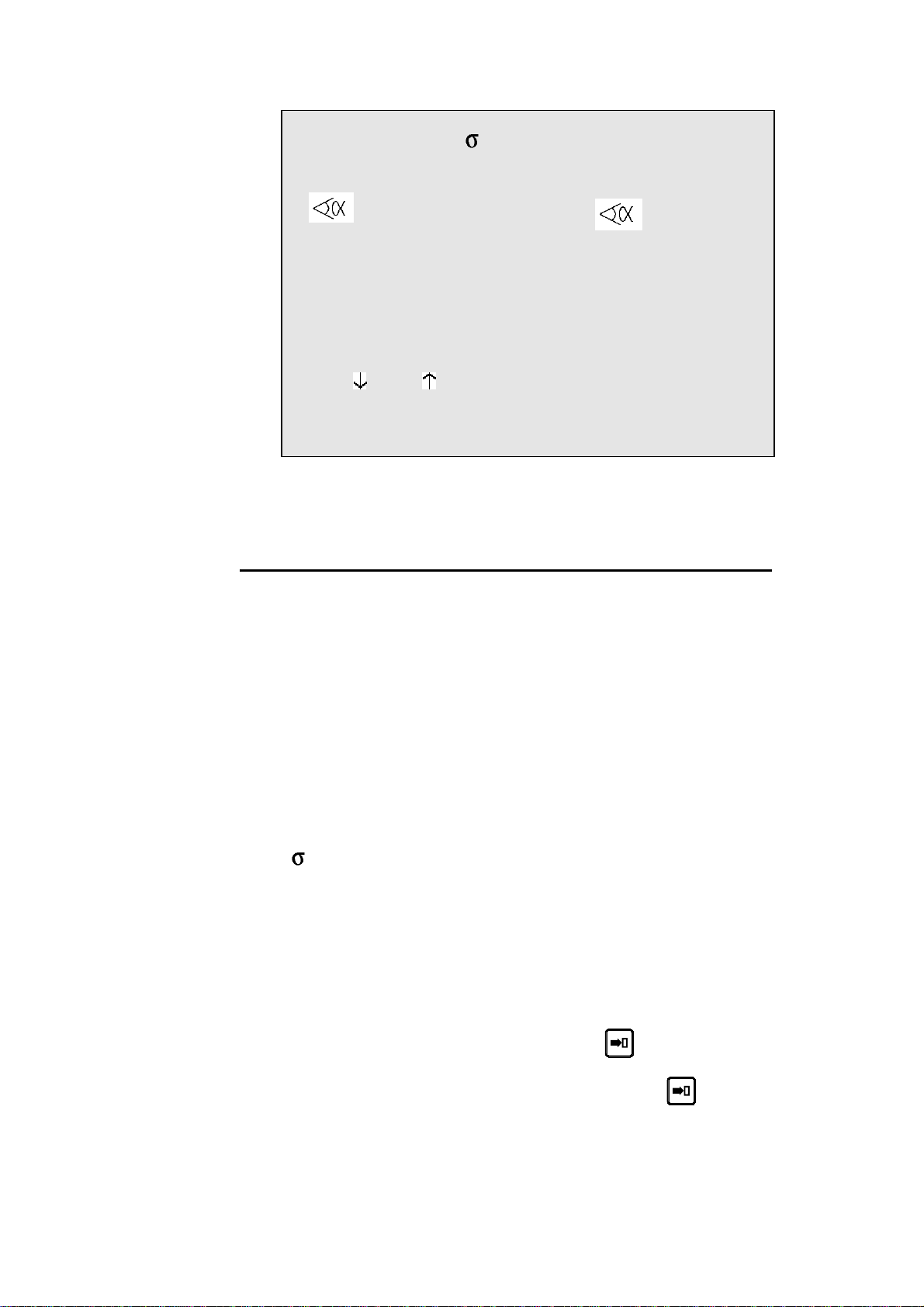
EASY BEND PAGE
The EASY BEND page is accessible by hitting the
key twice.
Easy Bend
Th: 2.00 σ 45.00 Kg/mm2 Ac_Al_In_
p/d 1/1 CR __/ri 2.78
--MEM-- --POS--
90.0° mes __._°
Y1 293.11 350.92
Y2 293.11 351.05
L 136.0
X1 133.9 51.8
Lp 5000 Fp 78
Rx ___ Start Ext _
Vy __% __% ΔTp _._s
PCV ___
This page makes it possible to quickly programme a bend, and/or briefly stop
production to perform a single bend without modifying or losing data in the
production programme.
PROGRAMMING A BEND
.
Enter the thickness and the tools if they differ from the product in the
course of production.
To speed up programming, the p/m fields as well as the material are
taken over from sequence 1 of the product currently in hand. The
modification of these data does not affect the programme that is running.
Enter the angle of the bend in the
Enter the height
the X gauge will be calculated automatically.
or
directly enter the distance at which the X
gauge is to be positioned.
Enter the length of the bend.
The system automatically calculates the pressure and bending.
Possibly also enter,
o how long the pressure is to be maintained (if not pro-
o the retraction of the gauge,
o the reduction in bending speed,
o slow liftin g, etc.
L of the wing (external measurement) and the position of
grammed, the default is = 0.5 s),
field
L
EASY BEND PAGE PAGE 5
Page 16

Press the START button or the pedal and the axes will position to the de-
sired values. The numerical command will automatically go into semiautomatic mode.
Actuate the pedal to bend.
When the beam returns, the DNC switches to programming mode.
You can now enter new data or actuate the pedal for a new bend.
Hit the
key to return to production mode.
EXPLANATION OF THE FIELDS
See Explanation of the fields page 8.
PAGE 6 USER GUIDE DNC 60 PS
Page 17
CREATING A PRODUCT
This paragraph explains how to programme a product as well as the method
for correcting and recording it.
THE SEQUENCE PAGE
This page displays all the bending information for the current sequence.
That is the requested position of the Y and X (R, etc.) axes, the pressure, the
gauge retraction, the crowning, the dwell time, etc.
Important This page displays the result of the calculations made when programming a
product in the L-alpha page with definition of the bending order.
The operator can modify these values if necessary (especially the retraction,
the dwell time, the top dead centre).
However he must avoid directly modifying the Y and X values calculated by
the DNC.
If modifications should be necessary for these axes, the correction page has
to be used.
Hint An operator can directly programme a product in this page, without "pass-
ing" through the L-alpha page and definition of the bending order.
This simplifies the manipulations a great deal, since all the information required for the bending are on this page.
To reach the sequence page, press the
The first press displays the dimensions page in large characters.
A second press displays all the dimensions and functions of the current sequence in small characters.
This page is displayed during the powering-on of the DNC.
To change from one sequence to another, press the
When the last sequence of the program is reached, the small LED of the
key lights up. At this moment, when pressing the key, a new se-
quence is created with the same contents as the last sequence. A message
COPIED is displayed.
On this page, the
field to another.
key is used to move the cursor from one significant
key.
or
key.
The
can be deactivated in the machine parameters.
If a product is removed, the data contained in the tool fields, the thickness
field and the material information fields continue to be displayed. This saves
the operator from having to reprogramme unchanged data.
CREATING A PRODUCT PAGE 7
key is used to move the cursor across all the fields. This function
Page 18
P 1 N 1 / 4 CY __
Th: 2.00 45.00 Kg/mm²
p/d 1/ 1 CR __/ri 2.78
--MEM-- --POS-- --COR--
90.0° mes____.__
Y1 293.11 350.92 ____.__
Y2 293.11 351.05 ____.__
L 136.0
X1 133.91 51.85 ____.__
Q ____ ____
Lp 5000 TON 78
Rx _ ___ Ext start _
Vy __% __% ΔT _._s
TDC ___ SP ___
F1:___ F2:___ F3:___ F4:__ F5:__ Cr: 41
EXPLANATION OF THE FIELDS
P
P+
N
CY
Th
p/d
Number of the product in the working memory.
Number of the following product when there is a
sequence of programmes.
Bending order (sequence) number to be made
and the total number of bends for the product.
Number of sequence repetitions.
(programmed 0, the sequence is jumped)
Material thickness.
The Greek symbol "Sigma" indicates the tensile
and rupture strength.
This field, as well as those showing the type of
material, can be hidden (see the
in the machine parameters).
If this field is hidden, the default value is
2
kg/mm
, but other values can be defined in the ad
hoc field in the machine parameters.
Number of the punch/die pair associated with the
bend to be made.
preferences page
steel 45
CR/ri
PAGE 8 USER GUIDE DNC 60 PS
In the P or D field press
of tools.
Select the tool in the list then press
return.
Number of bends requested when working with
ideal curve (min. 4), and internal bending radius.
to display the list
again to
Page 19
--MEM--
--POS--
--COR--
#The
, Y1, Y2, etc. fields are dependant on the axes programmed in
the numerical control.
L
Q
This column contains either the values calculated
by the system when simulating, or the values
programmed by the operator.
This column indicates the real axes' positions.
This column contains all the sequence and product corrections introduced on the
CORRECTION page.
Height of the wing after bending. The DNC will
automatically calculate the position of the back
gauge of axis X.
L
Number of product sequence repetitions. Quantity of products to be produced. The Q field is
displayed only if the parameter in the
PREFERENCES page is activated.
Lmat
TON
Rx
Ext start
Bending length.
Bending force.
Back gauge retraction. The operator indicates in
mm the retraction distance. If nothing is programmed, the beam doesn't stop at the CP. No
retraction.
If value 0 is introduced, the beam stops at the
CP, then executes immediately the bend without
carrying out a retraction.
The field between the Rx and the retraction
value serves to define the retraction mode.
_ = the beam stops at the CP and waits till the
retraction is made, in order to carry out the
bend.
1 = the beam stops at the CP, then continues
immediately, at the same time as the retraction is carrying out.
If nothing is programmed in this field, the axes
start automatically from the BDC, from the CP
or from the TDC, depending on the choice made
in the machine parameters.
If 1 is programmed, the start will be made as a
function of the configuration made by the constructor.
- In most of the configurations, it will be sufficient to give a down command. At this command, the axes take position, then a second
down command has to be given, in order to
move the beam.
CREATING A PRODUCT PAGE 9
Page 20

- In other configurations, the provided start
button must be pressed.
- When the message TOL ZONE appears, that
means that a down command has been given
and that the axes are not positioned in the
current sequence. Give a start with the provided button or on the front panel of the
DNC.
Vy
Vy
ΔT
TDC
SP
F1 - F5, Cr
These fields can also be re-programmed by the user.
However, certain fields are related, that is modifying one provokes a
modification of the other.
Beam bending speed.
Programmed at 0, the speed is 1 mm/s.
Programmed at 9, the speed is 10 mm/s.
(If the machine is capable of reaching this speed)
Rising speed from BDC to CP.
Programmable from 0 (slow) to 9 (fast).
Allows to vary the speed at which the beam rises
to the CP. (Function depending on the machine's
hydraulics).
Dwell time.
Distance from top dead centre.
Distance from the beam speed changing point.
(Switch Point).
Value of the auxiliary functions F1 to F5 and
crowning.
The auxiliary functions are displayed only if the
function is configured.
PAGE 10 USER GUIDE DNC 60 PS
Page 21
PROGRAMMING ON THE SEQUENCE PAGE
In this guide, it is considered that the DNC is configured so as to be op erational (i.e. machine and tool parameters programmed).
The operator has 2 methods available for programming.
The faster
Direct programming.
Direct programming is the faster method for an experienced operator, because all the programming of the product is done on the same page. This
makes it possible to programme the positions of the axes directly, and it calculates the depth of bending according to the angle entered.
With calculation of the development
The L-Alpha method.
The L-alpha method makes it possible to enter a profile to bend with the external dimensions and angle of each face. The DNC will calculate the developed length:
After having programmed the sequence of bends, the DNC will calculate the
position of the gauges.
Explanation of this method in chapter
on page 37
Annex F: Programming with L-alpha
DIRECT PROGRAMMING
Programming example
The following product is to be realized:
The bending order is the following:
Th: 2.0 mm
Lmat: 1000 mm
CREATING A PRODUCT PAGE 11
Page 22
Bend 1 on FACE 1 and LEG 0
Bend 2 on FACE 3 and LEG 4
Bend 3 on FACE 2 and LEG 3
Clear the memory Call the sequence page with the
Clear the work memory.
In the event of the removal of a product, the data contained in the
Tools fields, the Thickness field and the Material Information fields
remain (if displayed). This avoids the operator having to reprogramme
unchanged data.
Place the cursor in the N field (reminder:
the cursor on the top of the page).
key.
+ to position
PAGE 12 USER GUIDE DNC 60 PS
Page 23
Introduce 99 and press the
key.
P 125 P+__ N 99 / 4 CY __
Th: __.__ __.__ Kg/mm²
p/d _/_ CR __/ri __.__
--MEM-- --POS-- --COR- __._° mes____.__
Y1 ___.__ 350.92 ___.__
Y2 ___.__ 351.05 ___.__
X 1 ___.__ 51.85 ___.__
Q ____ ____
Lmat ____ Fb ___ TON
Rx ___ Ext start _
Vy _ _ ΔT _._s
TDC ___ SP ___
F1:___ F2:___ F3:___ F4:__ F5:__ Cr:__
Introduce the thickness, the sigma, the tools as below:
P 0 P+__ N 1 / 1 CY __
Th: 2.00 σ 37.00 Kg/mm²
p/d 1/1 CR __/ri __.__
Program 90 in the field,
by leaving the field, the system calculates the Y1 and Y2 axes' values.
Introduce 58.0 in the X field (stop position for this first bend).
Introduce the bending length 1000.
The system calculates the pressure and the crowning automatically.
If necessary, introduce the dwell time (by default non-programmed =
0.5 s), the gauge retraction, the bending speed reduction, the slow
raising, etc.
Press the sequence forwards key
quence in sequence 2.
The message COPIED is displayed, the N field passes on 2.
The LED of the key remains lighted, indicating that you are on the
last sequence.
, in order to copy this first se-
CREATING A PRODUCT PAGE 13
Page 24
2nd sequence The following screen is displayed:
Remark: the values Y1, Y2, Fb and Cr will vary, for they are calculated
as a function of the programmed tools. The values POS Y1,
Y2 and X will also be different, for they display the real position of the axes.
P 0 P+__ N 2 / 2 CY __
Th: 2.00 37.00 Kg/mm²
p/d 1/ 1 CR __/ri __.__
--MEM-- --POS-- --COR--
90.0° mes____.__
Y1 229.90 350.92 ____.__
Y2 229.90 351.05 ____.__
X 58.00 51.85 ____.__
Q ____ ____
Lmat 1000 TON 19
Rx ___ Ext start _
Vy _ _ ΔT _._s
TDC ___ SP ___
F1:___ F2:___ F3:___ F4:__ F5:__ Cr: 41
Modify the values which are different for this sequence, in this case enter 18
in the X field.
P 0 P+__ N 2 / 2 CY __
Th: 2.00 37.00 Kg/mm²
p/d 1/ 1 CR __/ri __.__
--MEM-- --POS-- --COR--
90.0° mes____.__
Y1 229.90 350.92 ____.__
Y2 229.90 351.05 ____.__
X 18.00 51.85 ____.__
Q ____ ____
Lmat 1000 TON 19
Rx ___ Ext start _
Vy _ _ ΔT _._s
TDC ___ SP ___
F1:___ F2:___ F3:___ F4:__ F5:__ Cr: 41
Press the sequence forwards key , in order to copy this second
sequence in sequence 3.
The message COPIED is displayed, the N field passes on 3.
The LED of the key remains lighted, indicating that you are on the
last sequence.
PAGE 14 USER GUIDE DNC 60 PS
Page 25
3rd sequence The following screen is displayed:
P 0 P+__ N 3 / 3 CY __
Th: 2.00 37.00 Kg/mm²
p/d 1/ 1 CR __/ri __.__
--MEM-- --POS-- --COR--
90.0° mes____.__
Y1 229.90 350.92 ____.__
Y2 229.90 351.05 ____.__
X 1 18.00 51.85 ____.__
Q ____ ____
Lmat 1000 TON 19
Rx ___ Ext start _
Vy _ _ ΔT _._s
TDC ___ SP ___
F1:___ F2:___ F3:___ F4:__ F5:__ Cr: 41
Modify the values which are different for this sequence, in this case
enter the value 48 in the X field.
The programming of the product is terminated.
If you wish to save:
Place the cursor on the P field.
(
and to position the cursor on the top of the page.)
Introduce the number you wish to give to this product.
Press
for saving this product).
The product will be saved in the internal memory with the number
which you have given it.
It will, however, remain present in the work memory.
Go to semi-automatic mode
Call the sequence 1.
Execute the first bend.
(if the system replies EXISTS, choose another number
.
CREATING A PRODUCT PAGE 15
Page 26
CORRECTION
It can happen that the angle bent is slightly greater or less than the angle programmed.
The operator has then the possibility to introduce the real value of the angle
bent. The DNC will correct the Y1 and Y2 axis values accordingly.
The corrections can be entered into two different pages:
Page corrections (see explanation on page 71).
Sequence page.
P 0 P+__ N 1 / 4 CY __
Th: 2.00 σ 37.00 Kg/mm2
p/d 1/1 CR __/ri __.__
--MEM-- --POS-- --COR--
90.0° mes 91.20
Y1 229.60 350.92 ____.__
Y2 229.60 351.05 ____.__
X 58.00 51.85 ____.__
Q ____ ____
Lp 1000 Fp 19 TON
Rx ___ Start ext _
Vy _ _ ΔTp _._s
PMH ___ PCV ___
F1:___ F2:___ F3:___ F4:__ F5:__ Bo: 41
The following working method is recommended:
Programme or call the product.
Switch to semi-automatic mode.
Execute first bend.
Measure the result.
Switch to programming mode.
Enter the measured angle into the COR field (see above). The DNC
automatically calculates the corrections to be made to Y1 and Y2.
If necessary, make the corrections to the gauge axes.
Bend a second product on the first bend to check the corrections.
Move to the following sequence and then proceed in the same way for
all subsequent sequences.
When all the bends are correct, switch to automatic mode and proceed
normally.
The correction entered above is applied only to the current sequence. Every
other sequence must be corrected individually.
Product-by-product correction is possible in the CORRECTION page (see
explanation on page 71).
PAGE 16 USER GUIDE DNC 60 PS
Page 27
PRODUCT MANAGEMENT
This chapter indicates how to manage the products (programs) stored in the
numerical control.
LIST OF PRODUCTS
Press the key.
P 1 NEW_P
CODE 623-42.15
SEQUENCES PROGRAMMED 42
AVAILABLE 306
-LIST OF PRODUCTS IN MEMORY-
1 2 11 222 997 ___ ___ ___ ___ ___
___ ___ ___ ___ ___ ___ ___ ___ ___ ___
___ ___ ___ ___ ___ ___ ___ ___ ___ ___
___ ___ ___ ___ ___ ___ ___ ___ ___ ___
The upper part of the screen displays the number of the product currently in
the work memory as well as the number of the drawing of that product.
The DNC also displays the number of sequences programmed, as well as the
number of sequences still available in the internal memory.
Then are displayed, in ascending order, the numbers of all the products
stored in the internal memory.
The NEW_P field enables the operator to create a new product directly,
starting from this page.
Position the cursor on NEW_P and press the
key.
PRODUCT MANAGEMENT PAGE 17
Page 28
SEEKING A PRODUCT BY CRITERIA
Press the key again.
P 28
-- CRITERIA - CODE
p/d __/__
Th __.__
Lmat _____
DevL ____.__
-- LIST OF PRODUCTS - P CODE p/d
___ __/__
___ __/__
___ __/__
___ __/__
This page allows to display a list of searched products according to one or
more criteria like the code number, the thickness, the bending length and/or
the unfolded length.
Under the heading --CRITERIA-- are displayed the different criteria according to which it is possible to search for a product.
These criteria can be combined, that is it is possible, for example, to ask for
the list of all the products stored using a specific tool pair and having a particular material thickness.
The products meeting the defined selection criteria are displayed on the second half of the screen.
To make a search by criteria, proceed as follows:
Introduce one or more selection criteria in the fields provided.
Press
If the list contains 7 or more products, the following page or pages can be
displayed by pressing
.
.
PAGE 18 USER GUIDE DNC 60 PS
Page 29
CALLING A PRODUCT
This operation seeks a product in the internal memory and place it into the
work me mory.
Calling a product is possible from all pages on which the cursor can be
placed on the P or CODE field.
Attention: The called product "erases" the product already in the work
memory. Pay attention to save, if necessary, the current product
before calling another product.
Introduce the product number in the P field or the code number in the
CODE field.
Leave the cursor on the field which has been programmed just now.
Press
The product requested is then copied into the work memory (the
original of this product is, of course, conserved in the internal memory).
.
SAVING A PRODUCT
This operation is used to permanently save a product located in the work
memory.
Saving a product is possible from all pages on which the cursor can be placed
on the P field.
It should be noted that after saving the product remains present in the work
memory.
To save a product proceed as follows:
If you wish to give a drawing number or name to the product, fill in
the CODE field. This operation is optional.
Enter the number of the product in the P field.
Leave the cursor in the P field.
Press the
If the system displays the message EXISTS, choose another number.
If you wish to save a product under a number which already exists (e.g. after
modifying a product), the product bearing that number must first be deleted
in the internal memory.
NB: Attention, the N° 998 and 999 are reserved for special functions.
998 for the temporary storage of the work memory contents during PC
<-> DNC transfer.
999 for total deletion of the internal memory (see page 20).
PRODUCT MANAGEMENT PAGE 19
key.
Page 30
DELETING A PRODUCT
Call the list of products page.
Place the cursor on the P field and introduce the number of the prod-
uct to be deleted.
Press
It should be noted that this action has no effect on the internal memory.
.
DELETING ALL THE PRODUCTS
Attention This operation deletes the totality of the products stored in the internal mem-
ory without the possibility to cancel this command.
Call the list of products page.
Introduce the value
Press
.
999 in the P field.
PAGE 20 USER GUIDE DNC 60 PS
Page 31

ANNEX A: CONVENTIONS
As a general rule, in this manual we will not repeat how to validate a field,
select a tool, call a page or any other basic manipulations.
This information is described at the beginning of this manual.
TYPOGRAPHICAL CONVENTIONS
Arial bold Quotations of text as seen on the screen.
Arial bold italic Used to indicate the name of a DNC input or
Italic Reference to a written element, a paragraph or a
output.
manual.
For example: See Annex A: Conventions.
ABBREVIATIONS / GLOSSARY
Explications of the abbreviations which are not visible fields in the pages of
the numerical control.
TDC Top dead centre.
SWP Switch point of speed, i.e. the change from ap-
PSS Safety point. This point is calculated in function
CP Contact point (see page 61).
BDC
LED Light Emitting Diode. Small red light serving as
proach speed in bending speed in the descent
phase.
of the tools height and the material thickness.
Bottom dead centre
luminous indicator.
ANNEX A: CONVENTIONS PAGE 21
Page 32

This page has been left blank intentionally.
PAGE 22 USER GUIDE DNC 60 PS
Page 33

ANNEX B: THE USER INTERFACE
THE SCREEN
The screen displays the products, tools and machine parameters as well as all
other useful information for programming and machine work.
The keys situated on the front of the DNC are used for selecting the screen
pages and introducing data.
A cursor indicates where the user can intervene.
On all pages, when first displayed the cursor is located on the programmable
field on which it was placed during the last intervention on that page.
The cursor can be moved to the previous or following field by pressing the
or key. Holding down one of the keys produces an auto-repeat
which moves the cursor forward or backward as long as the key is held
down.
Faster Regardless of the cursor position on the page , pressing the
keys simultaneously moves the cursor to the first programmable field
of the page.
THE KEYBOARD
The keyboard is divided into six zones:
Numerical keyboard
Screen page selection keys
Working mode zone
The commands
The cursor keys
The manual mode keys
NUMERICAL KEYBOARD
and the
The numerical keys as well as the and keys are used to introduce numbers or values into the different fields.
ANNEX B: THE USER INTERFACE PAGE 23
Page 34

THE SCREEN PAGE SELECTION KEYS
Main menu key
A dual-function key
Hitting the key once opens the MAIN MENU
page.
Hitting the key a second time displays the
BEND
EASY
Product list key
Double function key.
Pressing this key once displays the list of
products in the DNC memory.
Pressing the key again displays the search for
products by criteria page.
Product key
Triple function key.
Pressing this key once displays the angle
length (L-alpha) values.
Pressing a second time displays the bending
order with their respective legs.
Pressing a third time displays the bending
values which are calculated as a function of the
values introduced on the previous page.
Sequence key
Double-function key.
• Hitting the key once displays the dimen-
sions page in large characters.
• Hitting the key again displays all the
dimensions and functions of the current
sequence.
Correction key
This key displays the correction page which
allows to make corrections to the current sequence, as well as to the entire product.
PAGE 24 USER GUIDE DNC 60 PS
Page 35

THE WORKING MODES
Programming mode
Allows to introduce, modify and read data as
well as to store, search for and transfer programs.
Manual mode
Authorizes axis movement and auxiliary func-
tions using the
Semi-automatic mode
Allows a machine cycle with the current sequence values without automatic sequence
change.
This mode is used for adjustments when realizing the first product, as well as for products
with only one bend.
The sequence change is made using the
keys.
NB: The product counter Q does not function in this mode.
Automatic mode
Normal mode for product production.
The DNC automatically changes sequence
after each bend.
Changing directly from "programming" mode
automatically forces the first sequence of the
program.
Changing from "programming " mode to
"semi-automatic" mode and then to "automatic" mode, conserves the current sequence
for execution.
This allows to take up again a product in production without having to make "empty" cycles.
keys.
ANNEX B: THE USER INTERFACE PAGE 25
Page 36

THE COMMANDS
Delete key
Allows to delete a sequence or a program when
the cursor is placed on the PRODUCT or N
fields.
Only functions in programming mode.
Clear key
This key allows to delete data indicated by the
cursor.
Caution: pressing this key twice, on most
pages, deletes all the data on the page.
Search key
According to the cursor position allows:
- to search for a product
- to search for a sequence
- to search for a tool
- to search for a screen page
- to start a product feasibility calculation
- to transform L-alpha values into machine
values
- to calculate the unfolded length of the
sheet
- to execute a transfer
Only functions in programming mode.
Store / insert / teach key
Depending on the cursor position, allows to
store the current program in the DNC internal
memory, or create (insert) a new sequence in
the middle of an existing program, or copy
(teach) the value of an axis positioned manually in the current sequence.
This key is only valid in programming (memorization and insertion) mode and in manual
(teach) mode.
PAGE 26 USER GUIDE DNC 60 PS
Page 37

THE CURSOR KEYS
Sequence forwards / Page forwards key
This key allows to scroll pages of the same
type. Also allows to pass to the next page when
a series of information occupies several pages.
Eg.: program sequence
punch-die pages
production pages
parameter pages
In programming mode also allows to create an
identical sequence (copy function) to the previous one as long as this is the last sequence of
the program.
The incorporated LED indicates whether the
sequence is the last of the program.
Page backwards / Sequence backwards key
Inversed function of the
Allows to scroll backwards through pages of
the same type.
Functions in all modes except automatic mode.
key.
Cursor upwards, to the next accessible field.
and
Holding this key down causes an auto-repeat to
move the cursor back until the key is released.
Cursor downwards, to next accessible field.
Holding this key down causes an auto-repeat to
move the cursor forwards until the key is released.
This key combination positions the cursor in
the upper part of the current page.
ANNEX B: THE USER INTERFACE PAGE 27
Page 38

"MANUAL" ZONE
Start key
Commands:
- The displacement of the axis and auxiliary
functions. During movement the LED lights up
(except for the beam)
- An indexation at the beam (on option
depending on the configuration on other axes)
when this key is first pressed after switching
on the DNC.
To indicate that an index is being taken the
LED remains constantly alight, until the indexes are received. Indexes can only be taken
in
Stop key
Depending on the working mode chosen, stops
the axes or auxiliary functions, or stops the
calculation being executed.
When the DNC is in transfer mode (RS232)
the STOP key allows to terminate the transfer.
Manual displacement keys of the selected axes.
Allows, in the machine parameters, to configure the axis type, the inputs/outputs and to
select the display of the N2X axes.
or modes.
PAGE 28 USER GUIDE DNC 60 PS
Page 39

ANNEX C: THE MAIN MENU
By pressing the key on the top right of the keyboard, the main menu
appears.
CHOICE ? __
1 NEW PRODUCT
2 EASY BEND
3 LIST OF PARTS DNC/CRITERIA
4 LIST OF PUNCHES
5 LIST OF DIES
6 PROGR. PUNCHES / DIES
7 PRODUCT PUNCHES / DIES
8 PRODUCT STATUS; L;
9 PRODUCT BENDS; STOPS
10 PRODUCT X; ;Y
11 PROGR.AXES ORIGINS
12 TRANSFER DNC <-> PC
13 MACHINE PARAMETERS
14 MACHINE CONTROL
Regardless of which screen page you are on, you can always gain access to
the main menu by the
ent pages.
The option desired is chosen by entering the option number in the CHOICE
field on the first line of the screen and pressing the search
key, which allows you to circulate in the differ-
key.
ANNEX C: THE MAIN MENU PAGE 29
Page 40

CHOICE OF MAIN MENU
1 NEW PRODUCT
2 EASY BEND
3 LIST OF PARTS
DNC/CRITERIA
4 LIST OF PUNCHES
5. LIST OF DIES
6 PUNCH / DIE
PROGR.
7 PRODUCT
PUNCHES / DIES
8 PRODUCT STATUS;
L;
9 PRODUCT
BENDS;LEGS
Create a new product and display the page sequence,
ready for entering the data.
Access EASY BEND Page
Al
lows for quickly programming a bend and/or stopping production to quickly do another job (bend) without loss or modification of the program in hand.
This double page displays the list of parts held in DNC
memory and allows for selectively seeking parts.
Displays the list of punches.
Displays the list of dies.
From this page, it is possible to recall, program or delete a die or a punch.
This page allows to modify, for the product only, the
reference of a tool.
Generally called L-alpha page, this page displays and
allows the programming of products in "lengths and
angles" mode.
Displays the page allowing to program or modify the
bending order.
10 PRODUCT X;
; Y
11 PROGR. AXES
ORIGINS
12 TRANSFER
DNC <-> PC
13 MACHINE
PARAMETERS
14 MACHINE
CONTROLS
Displays for each sequence the calculated axis position.
Allows to program the axis position counter.
Allows the global or partial two way transfer of products, tools or machine parameters between the fixed
internal memory and a PC.
Displays a series of pages which allow to introduce,
display and modify the machine parameters.
Page allowing to control and to modify the state of
certain inputs and outputs (according to the configuration).
PAGE 30 USER GUIDE DNC 60 PS
Page 41

ANNEX D: THE MACHINE WORKING MODES
3 working modes are generally available at machine level.
The functioning is described hereinafter.
Depending on the manufacturers and the safety standards in force in the
country, the functioning can be different.
Adjustment mode
Sensitive mode
Automatic mode
These modes are independent of the DNC
be combined. Exception: the adjustment mode.
ADJUSTMENT MODE
This mode only functions with the DNC in mode.
If this is not the case, the press refuses to descend.
In this mode the table only functions in bending speed with the pressure and
speed programmed in the current sequence.
The top dead centre of the current sequence is active, it is thus not possible to
raise the beam above this point.
On the other hand, the bottom dead centre programmed in the sequence is not
active. Thus only stopping the descent command, or a mechanical stop
(punch in the die), or the lower limit switch will stop the beam in the descent
phase.
modes and can
ANNEX D: THE MACHINE WORKING MODES PAGE 31
Page 42

SENSITIVE MODE
DNC in mode
The functioning is identical to adjustment mode, except that the return to the
TDC is made in one movement.
DNC in or mode
The press works in the conventional way, that is:
High speed approach
Deceleration
Safety stop (if the mode requires it)
Bending
Bottom dead centre
It is at the bottom dead centre (BDC) that the differences appear.
The DNC remains under pressure at the bottom dead centre until the descent
command disappears, and this indifferently to the dwell time at BDC.
When the descent command is suppressed, the DNC remains at the BDC
without pressure or descent command, until reception of a rise command
which it executes immediately.
AUTOMATIC MODE
This mode functions in a similar way to sensitive mode, except that the raising of the beam is made automatically once the dwell time programmed in
the current sequence has elapsed.
This even if the descent command remains active.
NB: In all these modes the ascent command has priority. It is executed immedi-
ately on its reception.
PAGE 32 USER GUIDE DNC 60 PS
Page 43

ANNEX E: TOOL PROGRAMMING
The DNC 60 has several pages which allow consultation of the list of existing tools, to display them and / or program new ones.
The DNC 60 memory can hold a maximum of 20 punches and 30 dies.
LIST OF PUNCHES
From the main menu choose option LIST OF PUNCHES.
The system displays the list of punches existing in the memory, with
the number and characteristics of each punch:
LIST p/d 1/ 1
p/d 1/__ __/__ __/__ __/__
PUNCH
p 90° ___° ___° ___°
hp 100.00 ___.__ ___.__ ___.__
rp 1.50 ___.__ ___.__ ___.__
TON/M 100 ___ ___ ___
DIE
Vd ___.__ ___.__ ___.__ ___.__
d ___° ___° ___° ___°
hd ___.__ ___.__ ___.__ ___.__
rd ___.__ ___.__ ___.__ ___.__
TON/M ___ ___ ___ ___
REF Y ___.__ ___.__ ___.__ ___.__
SAF X ___.__ ___.__ ___.__ ___.__
If your DNC contains more than 4 punches, you can call the following page
or pages by pressing
.
List of dies
From the main menu, choose option LIST OF DIES.
The consultation of the list of dies can be done in the same way as explained
for the punches.
ANNEX E: TOOL PROGRAMMING PAGE 33
Page 44

PUNCH / DIE PROGRAMMING
GENERAL EXPLICATIONS
The programming of tools is done by introducing their values and dimensions on the page as represented below.
Call the PROGRAMMING PUNCH / DIE page (via the main menu).
p Punch angle.
hp
rp
TON/M
Vd
d
hd
rd
TON/M
REF Y
SAF X
Height of the punch between the lowest part of
the beam and the point of the punch.
Punch radius.
Maximum force supported by the punch per
linear meter.
V width of the die.
V angle of the die.
Height of the die from the surface of the table.
Die radius.
Maximum force supported by the die per linear
meter.
Sum of the hp and hd.
This value is automatically calculated during
programming of pairs. See The tool reference.
X Safety distance.
programmed = half V opening)
(Not
a: and b:
PAGE 34 USER GUIDE DNC 60 PS
Table and die dimensions according to the
drawing displayed on the screen.
Page 45

PROGRAMMING A PUNCH
On the PUNCH / DIE PROGRAMMING page, delete the values on
this page by pressing the
Fill in the different fields.
If you wish to save this new punch proceed as follows:
a) Place the cursor on the PROGR. p/d field and introduce the
number you wish to give to this punch as indicated below.
Attention: The die N° must not be programmed.
b) Press
c) If the system displays the message EXISTS, choose another num-
ber.
.
key twice.
PROGR. p/d 1/__
PUNCH
p 90°
hp 100.00
rp 1.50
TON/M 100
DIE
Vd 15.00
d 90°
hd 100.00
rd 1.50
TON/M 100
REF Y 200.00
SAF X 10.00
a: 20
b: 30
Create a punch by modifying an existing one
On the PUNCH / DIE PROGRAMMING page.
Call the punch which will serve as a basis.
Place for that the cursor in the p field, introduce the desired number
and press the
Modify the values as necessary.
Save the new punch by introducing its number in the p/ field and
press the
ANNEX E: TOOL PROGRAMMING PAGE 35
key.
key.
Page 46

MODIFY AN EXISTING PUNCH
On the PUNCH / DIE PROGRAMMING page.
Call the punch which will serve as a basis.
Place for that the cursor in the p field, introduce the desired number
and press the
Modify the values as necessary.
To be able to save this punch under the same number, the former ver-
sion must first be deleted from the internal memory.
Place the cursor on the punch number and press the
Leave the cursor at the same place and press
Attention: The die N° must not be programmed.
The former version of your punch has now been replaced by the new
one which has the same number.
DELETE A PUNCH
Call the LIST OF PUNCHES page (via the main menu).
Introduce the number of the punch to be deleted in the p/ field.
key.
key.
.
Press
.
PROGRAMMING A DIE
The programming of a die is done in the same way as for a punch, but in the
/m field.
PAGE 36 USER GUIDE DNC 60 PS
Page 47

ANNEX F: PROGRAMMING WITH L-ALPHA
In this manual, it is being assumed that the DNC is configured in such a way
as to be operational (i.e. the tools and machine parameters have already been
programmed).
2 programming methods are accessible by the operator.
The L-alpha method.
The L-alpha method allows to enter a profile to be bended with the external
dimensions and angles of each face. The DNC calculates the unfolded length.
After having programmed the bending order, the DNC will calculate the stop
positions.
Before starting to program a product, make sure that the tools necessary to
make the product exist in the DNC memory and write down the numbers of
the punches and dies to be used.
To do this proceed as described below:
If you are already familiar with the tools present in the DNC, you may pass
directly to chapter
Programming on the L-alpha page, page 38).
ANNEX F: PROGRAMMING WITH L-ALPHA PAGE 37
Page 48

Consulting the list of punches
To display the tools list in the P or M field, hit the key.
Select the tool from the list then press
If you don't find a punch which corresponds to your needs, you can create
one.
In this case refer to chapter Annex E: Tool programming, page 33.
It
is possible, if more than four punches are programmed to see them by
pressing the
key.
again to return
Consulting the list of dies
Proceed in the same way as described above for punches; access from the
main menu LIST OF DIES.
PROGRAMMING ON THE L-ALPHA PAGE
The PRODUCT STATUS page is often called L-alpha page for its programming method.
On this page, a product is programmed by defining its profile by the length
and the angle of each face.
Call the L-alpha page using the
choosing PRODUCT STATUS.
This page presents as follows:
key, or by passing via the main menu
P 0 P+ ___ N 1 I/mm
CODE CAL_/__.__
p/d __/__ St:_ Al:_ SS:_
Th: __.__ Kg/mm² ___.___
Lmat _____ Dev L ____.__
-N- -L- - - -p/d- -ri- CR TOL
1 ____.__ ____._°__/__ ____.__ __ ___
2 ____.__ ____._°__/__ ____.__ __ ___
3 ____.__ ____._°__/__ ____.__ __ ___
4 ____.__ ____._°__/__ ____.__ __ ___
5 ____.__ ____._°__/__ ____.__ __ ___
6 ____.__ ____._°__/__ ____.__ __ ___
7 ____.__ ____._°__/__ ____.__ __ ___
8 ____.__ ____._°__/__ ____.__ __ ___
9 ____.__ ____._°__/__ ____.__ __ ___
10 ____.__ ____._°__/__ ____.__ __ ___
PAGE 38 USER GUIDE DNC 60 PS
Page 49

Remark: On the following pages, you will find a systematic explication of all the fields
which figure on the L-alpha page.
If you wish to just follow the procedure, you may pass directly to chapter
L-alpha method, page 43.
L-ALPHA PAGE: EXPLICATION OF THE FIELDS
P
Product number
- existent in the work memory or
- to be created or
- to be searched for
The product number must be a number of a
maximum of 3 digits between 1 and 997.
(998 and 999 are reserved numbers)
If the product is created from an empty page,
the field contains the number 0.
The field keeps this value as long as the product has not been stored.
ANNEX F: PROGRAMMING WITH L-ALPHA PAGE 39
Page 50

P+
Number of the next product which will be
executed automatically.
If this field is left empty, when the last sequence of the product is executed, the program
will return to the first sequence of the current
product.
If it contains a product number, it will be executed immediately at the end of the current
product.
This allows to follow on several programs one
after another. Do not forget to program in the
last program the number of the first program in
order to close the loop.
N
I/mm
CODE
CAL
p/d
St:
Al:
S.S.:
Number of the current sequence, whose axe's
values are displayed on the sequence page.
Allows to choose the unit of length.
Programmed at 1, the face length values are
expressed in Inches.
Not programmed or programmed with a value
other than 1, the data is displayed in millimetres.
Code name or number (facultative), allowing
to associate supplementary information with
the product number in order to facilitate product management and searching.
For the introduction of alphanumerical characters, see
Allo
Alphanumerical characters, page 73.
ws automatic compensation of variations
in sheet metal thickness.
For programming this field, refer to chapter
Calibration, page 66.
Punch and di
e of the current product.
Choice of product material, steel, aluminium or
stainless steel.
Program 1 in the field next the material used.
If no field is programmed, steel is used by
default.
Th:
Kg/mm²
Lmat
Dev L
PAGE 40 USER GUIDE DNC 60 PS
Material thickness.
(Sigma) Tensile strength.
Bending length.
Unfolded length of the product calculated by
the system according to DIN 6935 standard.
Page 51

L-ALPHA PAGE : EXPLICATION OF THE COLUMNS
Each line (except the last) of the table on the PRODUCT STATUS page
represents data related to one bend.
-N- -L- - - -p/d- -ri- CR TOL
1 ____.__ ____._°__/__ ____.__ __ ___
2 ____.__ ____._°__/__ ____.__ __ ___
3 ____.__ __
-N-
-L-
80.00 60.00 80.00 85.00 120.00
Automatic numbering of the faces.
A "face" is defined as being that part of the
sheet metal situated between two bends or
between the edge of the sheet and a bend.
The maximum number of faces which can be
programmed for a product is 14. If more sequences are needed, use the chaining of product function (see previous page, field P+).
Face length. Designates the distance between
two bends or the distance between the edge of
the sheet and the first bend.
←⎯→
Length
-
-
p/d
-ri-
ANNEX F: PROGRAMMING WITH L-ALPHA PAGE 41
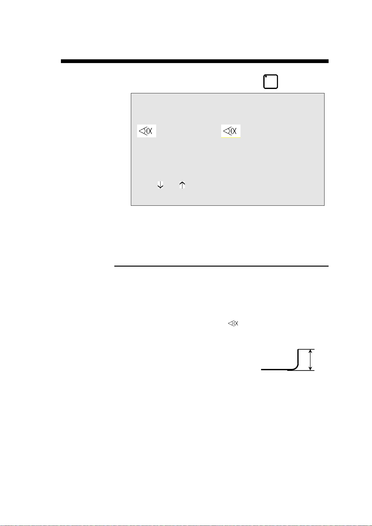
Bending angle.
Allows, for a given bend, to define a special
tooling pair different from the one specified for
the product.
If the adjacent field CR (ideal curve) is empty,
when the
indicates the internal bending radius calculated
taking into account the angle, the material and
the tools.
The operator can enter the value of the internal
radius which he considers to be correct, then
introduce the value 1 in the CR field.
key is pressed, the ri field
Page 52

During the calculation, the TOL (tolerance)
field indicates the distance defined according to
the TOL explication below.
When working with ideal curve, this field
indicates the theoretical radius requested by the
operator. (See Ideal curve, page 68).
ber of bends requested when working
CR
Num
with ideal curves. (See Ideal curve, page 68).
s number must be between 3 and 99. The
Thi
value 2 makes it impossible to change modes.
Remark: This number must be such that the
length of the ideal curve segments
are greater than half the length of
the die V opening.
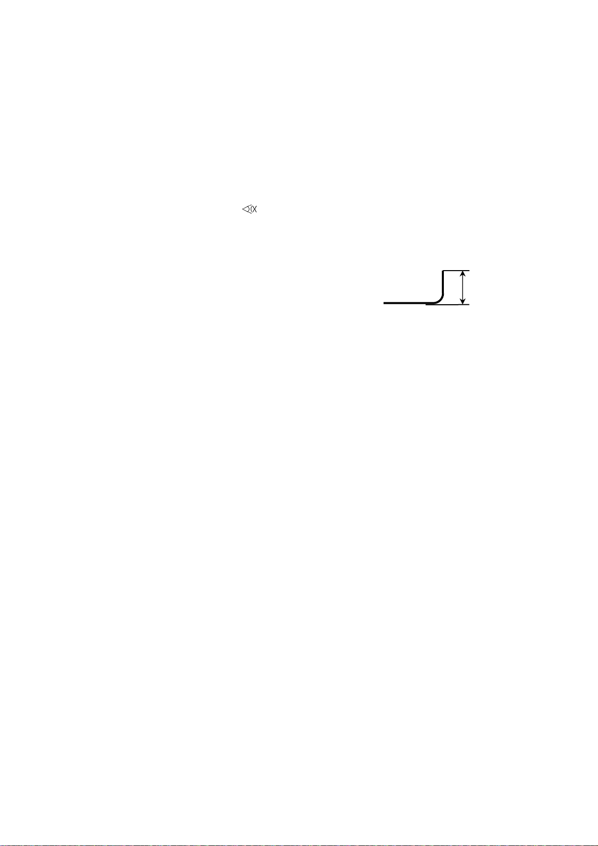
TOL
Tolerance. If the value in the CR field is equal
to 1, the tolerance indicates the value according to the illustration below.
R1 = Bending radius introduced by the
operator.
ri = Bending radius calculated by the system.
If the value in the CR field lies between 4 and
99, indicates the difference between the chord
formed by two bends and the arc of the theoretical circle, that is the difference between the
theoretical radius ri and the apex A of the
chord.
ri = Theoretical bending radius requested by the operator.
A = Apex.
For an example of ideal curve, see Ideal curve, page 68.
PAGE 42 USER GUIDE DNC 60 PS
Page 53

L-ALPHA METHOD
1. If you have it not already on screen, call the PRODUCT L-alpha
page.
The screen displays the data concerning the product in the work
memory at present.
2. In order to program a new product, the work memory must be cleared
by deleting the product already there.
If you do not wish to loose that product, you can transfer it to the internal memory by following the instructions below; if the current
product is not important or has already been saved, you can pass directly to point 4.
3. To save the product:
Place the cursor on the P field.
(
Type the number which you wish to give to this product.
Press
ber for saving this product).
The product will be saved in the internal fixed memory with the
number which you have given it.
It will, however, remain present in the work memory.
4. Delete the product from the work memory:
Place the cursor on the N field.
Introduce the value
Press the
The work memory is now empty.
Note that this operation only acts on the work memory and don't
destroy the data contained in the internal memory.
and
to position the cursor on the top of the page.)
(if the system replies EXISTS, choose another num-
99.
key.
ANNEX F: PROGRAMMING WITH L-ALPHA PAGE 43
Page 54

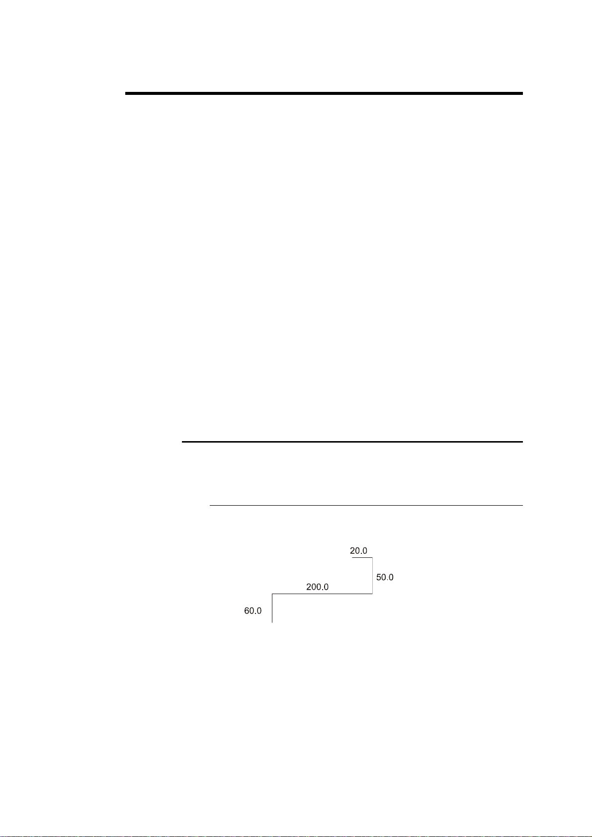
5. The product in our example is defined as follows:
Thickness: 2 mm
Sigma: 45 Kg/mm²
Material: Steel
Bending length: 250 mm
6. Fill in the fields on the screen according to the model below, taking in
to account the following particularities:
CODE: Optional field.
p/d Insert the numbers of the tools which you have previously
located (see point: consulting the list of punches or dies).
Then fill in the table columns.
Your screen should present as follows (but with the punch and die
numbers corresponding to your tools):
P 0 P+ ___ N 1 I/mm
CODE EXAMPLE-01 CAL_/__.__
p/d 1/ 1 St:1 Al:_ SS:_
Th: 2.00 Kg/mm² 45.000
Lmat 250.000 Dev L ____.__
-N- -L- - - -p/d- -ri- CR TOL
1 80.00 -90.0°__/__ ____.__ __ ___
2 60.00 90.0°__/__ ____.__ __ ___
3 90.00 135.0°__/__ ____.__ __ ___
4 85.00 -135.0°__/__ ____.__ __ ___
5 120.00 ____._°__/__ ____.__ __ ___
6 ____.__ ____._°__/__ ____.__ __ ___
7 ____.__ ____._°__/__ ____.__ __ ___
8 ____.__ ____._°__/__ ____.__ __ ___
9 ____.__ ____._°__/__ ____.__ __ ___
10 ____.__ ____._°__/__ ____.__ __ ___
7. After introducing the last length, press the key.
The system calculates the radius of each bend as well as the unfolded
length of the product and displays these values on the screen.
PAGE 44 USER GUIDE DNC 60 PS
Page 55

Save this product in the internal memory by proceeding as follows:
Introduce the number you wish to give the product in the P field, in
this case the number 1 for this product which will be used later as an
example.
Press the
If the system replies with the message EXISTS, choose another number.
key.
MODIFICATION OF A PRODUCT
If you wish to modify a product programmed in L-alpha, call the product
from the PRODUCT L-alpha page.
Delete a bend
Place the cursor on the N field and enter the number of the face to be
deleted. :
Press the
key; the face containing the bend is deleted.
Add a bend
Place the cursor on the N field and enter the number of the face in
front of which you wish to insert a new face. :
Press
rent bend. Modify the LENGTH and ANGLE fields.
Start the calculation by pressing
Continue in the next chapter. The definition of the bending order has
to be reprogrammed.
.The system inserts a line and copies the data of the cur-
.
ANNEX F: PROGRAMMING WITH L-ALPHA PAGE 45
Page 56

DEFINITION OF THE BENDING ORDER
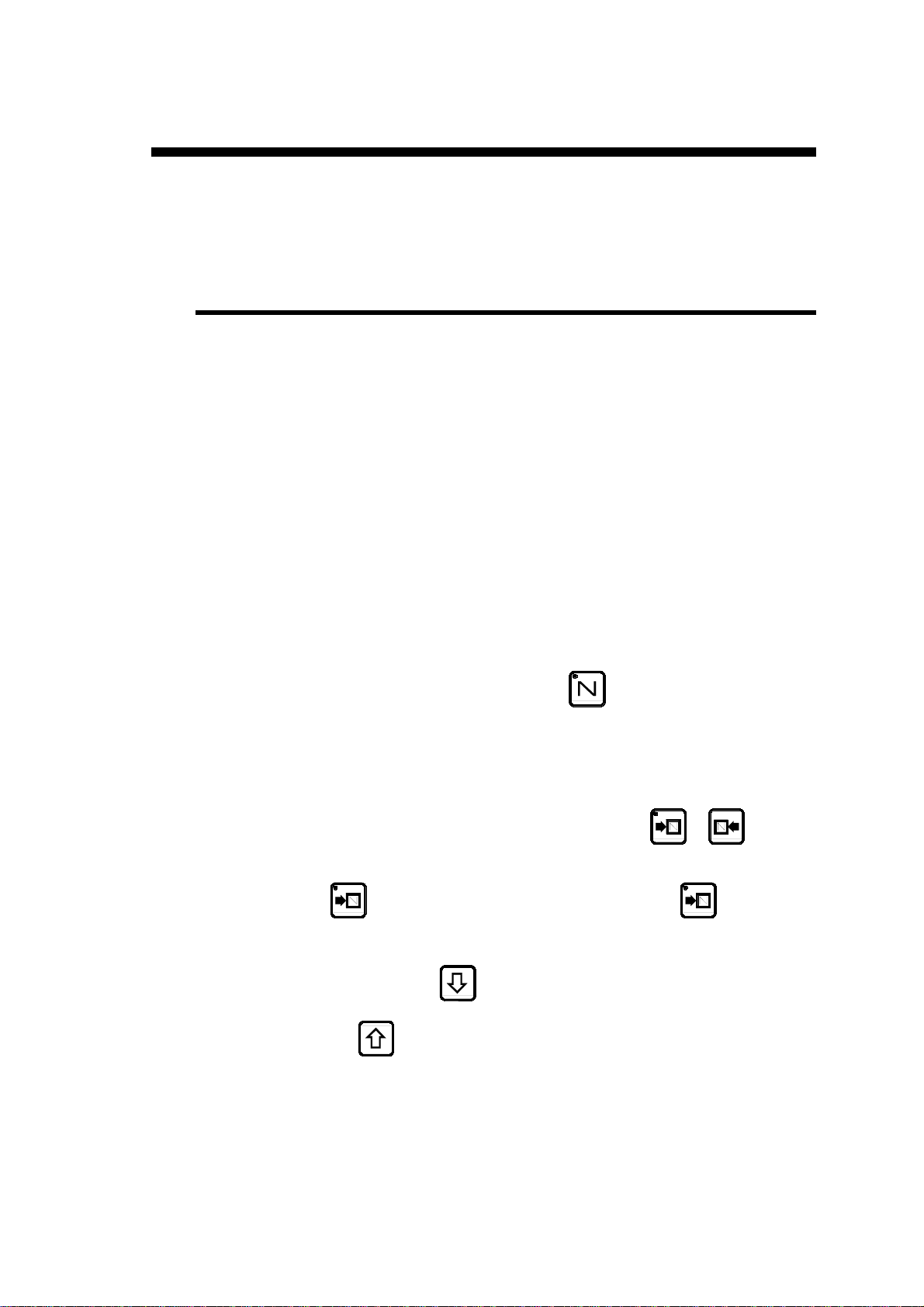
Press the key, to display the bending order page (Choice 9,
PRODUCT BENDS, STOPS of the main menu).
P 1 N 1 p/d 1/ 1
N FACE LEG CR p/d
1 __ __ __ __/__
2 __ __ __ __/__
3 __ __ __ __/__
. . .
14 __ __ __ __/__
Explication of the table columns
N
FACE
LEG
CR
Number of the sequence.
Face number.
Number of the face which will press against
the stop.
The orientation of the legs is made as a function of the bending order.
Number of bends requested when working
with ideal curve.
p/d
PAGE 46 USER GUIDE DNC 60 PS
Definition of a tooling pair for a particular
bend (if different from the pair specified in the
p/d field at the top of the page).
Page 57

Example a
For this example we will use the previously created product.
It was stored under the number 1. (If you cannot find it, create it by following the instructions of page 43).
Call the product number 1 by entering its number in the P field, and
then pressing the
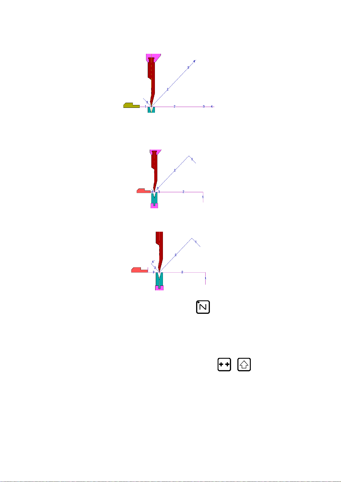
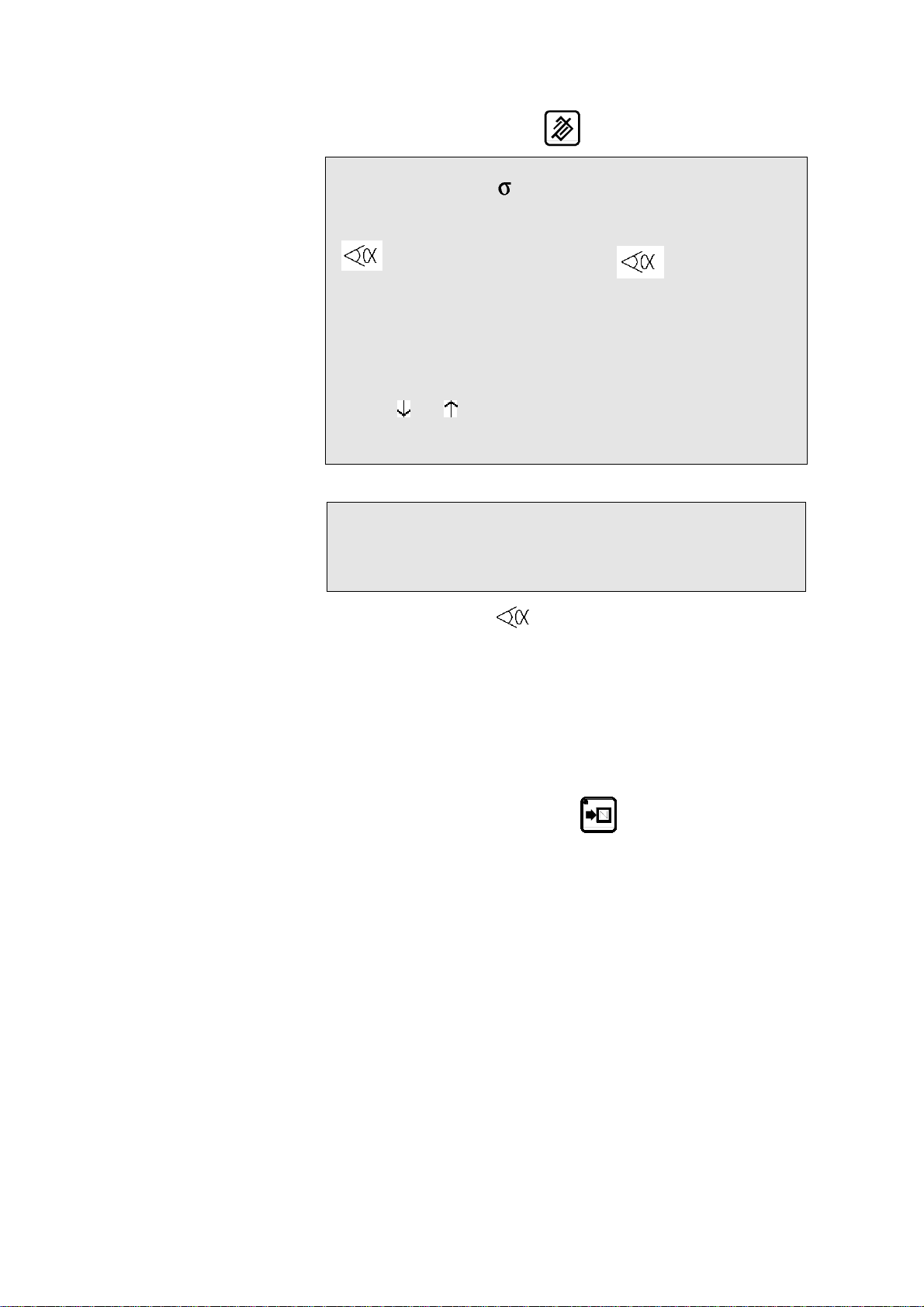
The following illustrations show you the desired b ending order.
For each sequence, the illustration shows the sheet metal with its bend before
and after bending.
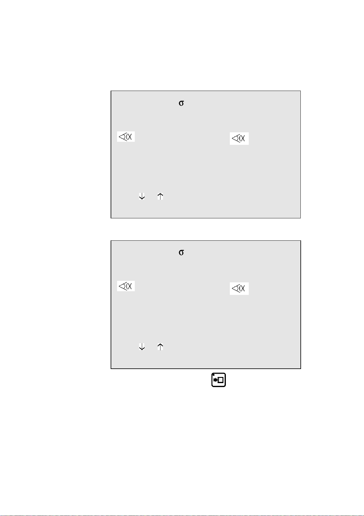
Sequence N 1: Face 1 and Leg 0
Sequence N 2: Face 3 and Leg 1
key.
Sequence N 3: Face 2 and Leg 1
ANNEX F: PROGRAMMING WITH L-ALPHA PAGE 47
Page 58

Sequence N 4: Face 4 and Leg 5
To introduce this bending order:
Fill in the FACE and LEG fields as follows:
N FACE LEG CR p/d
1 1 0 __ 1/ 1
2 3 1 __ 1/ 1
3 2 1 __ 1/ 1
4 4 5 __ 1/ 1
Press the key.
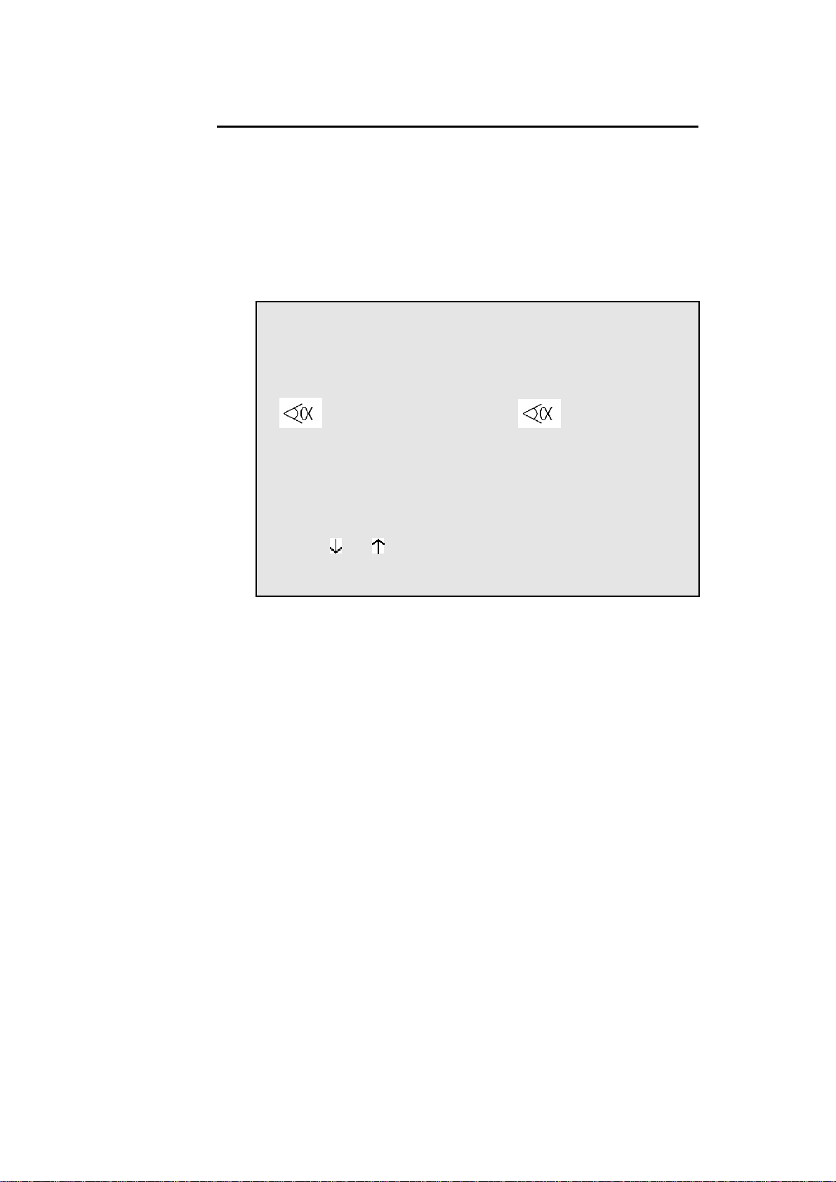
The system calculates the entire machine program (axes, functions, etc.) and
displays the sheet metal manipulations to be made before each sequence.
(See the Sheet metal manipulation diagram below).
N FACE LEG CR p/d
1 1 0 __ 1/ 1
2 3 1 __ 1/ 1 RETURN
3 2 1 __ 1/ 1
4 4 5 __ 1/ 1 SWIVEL
1 Return
2 Swing
3 Swivel (= Swing 180° + return)
PAGE 48 USER GUIDE DNC 60 PS
Fig. Sheet metal manipulation
Page 59

By pressing the
X;
values (the values depend on the used material and tools).
; Y page which displays for each sequence the X and Y axes'
key, you can consult the PRODUCT;
P 1 N 1
N -X- - - -Y- CY
1 78.06 90.0° 229.90 __
2 145.51 135.0° 233.58 __ RETURN
3 58.06 90.0° 229.90 __
4 119.39 135.0° 233.58 __ SWIVEL
5 _____.__ ___._° ___.__ 0
6 _____.__ ___._° ___.__ __
7 …………
Example b
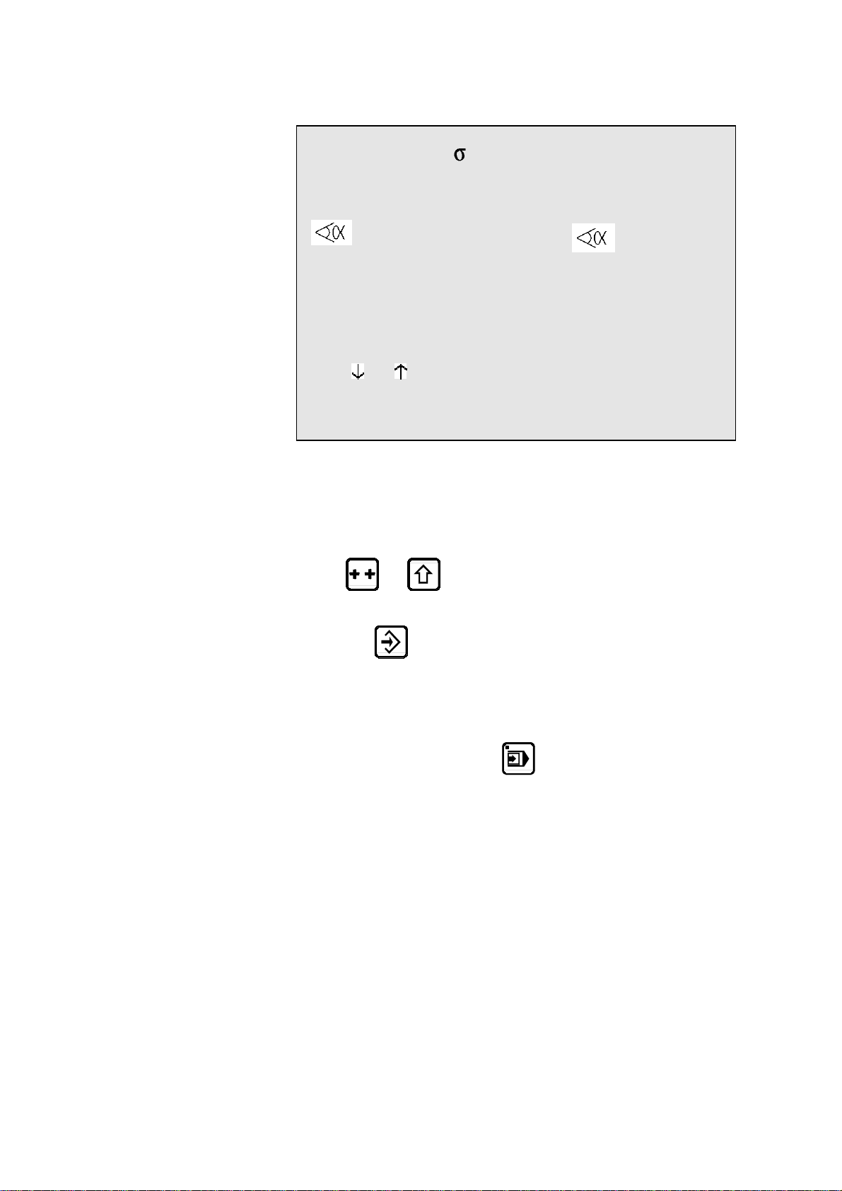
Here is an other bending order.
For this new bending order, the following illustrations show each sequence
before and after bending.
Sequence N1: Face 4 and Leg 0
Sequence N2: Face 1 and Leg 0
ANNEX F: PROGRAMMING WITH L-ALPHA PAGE 49
Page 60

Sequence N 3: Face 2 and Leg 1
Sequence N 4: Face 3 and Leg 2
Call the bending order page by pressing the
Fill in the FACE and LEG fields as below.
You will remark that the p/d fields are already programmed since we
have already made a calculation before.
key twice.
N FACE LEG CR p/d
1 4 0 __ 1/ 1
2 1 0 __ 1/ 1
3 2 1 __ 1/ 1
4 3 2 __ 1/ 1
Press the key.
The system calculates the entire machine program (axes, functions, etc.) and
displays the sheet metal manipulations to be made before each sequence.
N FACE LEG CR p/d
1 4 0 __ 1/ 1
2 1 0 __ 1/ 1
3 2 1 __ 1/ 1 RETURN
4 3 2 __ 1/ 1
PAGE 50 USER GUIDE DNC 60 PS
Page 61

By pressing the
; Y page.
This page displays for each sequence the X and Y axes' values (the
values depend on the used material and tools).
key, you can consult the PRODUCT; X;
P 1 N 1
N -X- - - -Y- CY
1 305.42 135.0° 233.58 __
2 78.06 90.0° 229.90 __
3 58.06 90.0° 229.90 __ RETURN
4 89.39 135.0° 233.58 __
5 _____.__ ___._° ___.__ 0
6 _____.__ ___._° ___.__ __
Call the sequence page
Pass to semi-automatic mode
Call the sequence 1.
Execute the first bend.
.
.
For corrections, go to page 71.
ANNEX F: PROGRAMMING WITH L-ALPHA PAGE 51
Page 62

This page has been left blank intentionally.
PAGE 52 USER GUIDE DNC 60 PS
Page 63

ANNEX G: MAINTENANCE AND MISCELANEOUS
THE INITIALIZATION PAGE
This page appears if a calculation is impossible, due to unprogrammed data
or an incorrect value.
It can also appear as a result of pollution of one of the memory zones which
will also give impossible calculations.
INITIALIZATION DNC 60 PS
-- MEMORY ZONE --
_ Clear variables zone
_ Clear punches-dies zone
_ Clear machine parameters zone
EXECUTION CODE ___
It can be necessary to display this page intentionally in order to clear completely the data of the DNC and to re-start the programming on a "clean" basis.
To display the initialization page:
Switch on the machine by pressing the
In case of unexpected apparition of the init page, proceed as follows:
If point n° 1 does not re-establish a normal situation, go on to the next point
and so on.
The following operations clear successively all the data in the selected
memories.
It is therefore recommended to re-introduce the data.
1) Press the
2) Enter:
value
1 in the field Clear variables zone
and value
Press the
key twice.
817 in the field EXECUTION CODE.
key.
and keys.
Press the
ANNEX G: SUNDRIES PAGE 53
key twice.
Page 64

3) Enter:
value
1 in the field Clear variables zone,
1 in the field Clear punches-dies zone
value
and value
Press the
Press the
4) Enter:
value
value
value
and value
Press the
Press the
The clearing of the machine parameters deletes also all the input / output
configuration defined by the operator.
817 in the field EXECUTION CODE.
key.
key twice.
1 in the field Clear variables zone,
1 in the field Clear punches-dies zone,
1 in the field Clear machine parameters zone
817 in the field EXECUTION CODE.
key.
key twice.
It is therefore advisable to re-configure the DNC 60 before the next use.
Attention: If you use an external system for the data re-introducing
(CYBACK via RS232) and the problem persists, then the information reentered by this system has to be called into question.
The best to do in this case is to delete again the whole contents o f the DNC
and to re-program the DNC manually via the keyboard (not the RS232 line).
PAGE 54 USER GUIDE DNC 60 PS
Page 65

IN CASE OF FAILURE
INITIAL CHECKS TO BE CARRIED OUT
Switch the machine off then on again.
Check the program (safety factors).
Check that the axes can be moved in manual mode.
Compare the machine parameters to those on the written list made
during the installation.
Check the power supply voltages (to do this please refer to the tech-
nical manual).
Check that the keyboard responds.
Check that the front panel lamps light up.
POSSIBLE MEMORY POLLUTION
After performing the initial checks above, it is then likely that you have a
memory pollution problem. To locate the fault, proceed as follows:
Switch off the DNC.
Switch on the DNC.
Follow the instructions in the next chapter The Initialization page.
ANNEX G: SUNDRIES PAGE 55
Page 66

THE INITIALIZATION PAGE
This page appears if a calculation is impossible, due to unprogrammed data
or an incorrect value.
It can also appear as a result of pollution of one of the memory zones which
will also result in impossible calculations.
INITIALIZATION DNC 60 G
---------
--MEMORY ZONE--
_ Clear variables zone
_ Clear machine parameters zone
_ Clear transmission RS232 zone
EXECUTION CODE ___
It may be necessary to use this page intentionally in order completely clear
the data on the DNC and to re-start the programming on a "clean" basis.
To display the Initialization page, press the
If the Initialization page appears unexpectedly, proceed as follows:
Note: If point 1 does not re-establish a normal situation, go on to the next
point and so on. The following operations clear successively all the data in
the selected memories. It is therefore recommended to re-introduce the data.
5) Press the
6) Enter:
- value
1 in the Clear variables zone field
817 in the EXECUTION CODE.field
- value
Press the
Press the
key twice.
key.
key twice.
and keys.
PAGE 56 USER GUIDE DNC 60 PS
Page 67

7) Enter:
- value
1 in the Clear variables zone field,
- value
- value
Press the
Press the
8) Enter:
value
value
value
and value
Press the
Press the
Clearing the machine parameters also deletes all the input / output configuration defined by the operator.
1 in the Clear machine parameters zone field
817 in the EXECUTION CODE field.
key.
key twice.
1 in the field Clear variables zone,
1 in the field Clear machine parameters zone,
1 in the field Clear transmission RS232 zone
817 in the field EXECUTION CODE.
key.
key twice.
We therefore recommend that the DNC 60 be re-configured before next use.
Important: If you use an external system for re-entering data (CYBACK
via RS232) and the problem persists, then the information re-entered by this
system have to checked again.
The best thing to do in this case is to again delete the who le contents of the
DNC and to re-program the DNC manually via the keyboard (not the RS232
line).
BEFORE CALLING FOR TECHNICAL HELP
Please have ready the following information:
Type of numerical control.
Serial Nr of the DNC.
DNC and axes (N2X) software numbers.
Name of the machine tool's manufacturer.
List of machine parameters (have on hand when the technician
comes).
The state of the numerical control:
- which LEDs are on?
- which message is on the screen ?
Details of what caused or is causing the problem.
ANNEX G: SUNDRIES PAGE 57
Page 68

THE TOOL REFERENCE
The machine has been adjusted according to the following principle:
When, theoretically, the punch's leg face on the beam is in contact with the
surface of the table, the value of the Y1 and Y2 counters is 000.00.
In practice this adjustment is made using two calibrated blocks, whose value
has been introduced into the counters.
Definition:
The reference value (REF Y) is theoretically the sum of the heights of both
tools; punch and die.
The height of the punch is the distance between the "point" of the punch and
its leg face on the beam.
The precision of all bends realized by the machine depends on the reference
value REF Y.
The numerical control calculates the bending depth using:
the REF Y value,
the geometrical values of the tools,
the sheet metal thickness.
If the resulting bends differ greatly from the programmed value, the reference and the values above must be controlled.
PAGE 58 USER GUIDE DNC 60 PS
Page 69

To control the reference, simply, in
mode, place the point of the punch
on the flat of the die (be careful with the pressure of the active sequence) and
read the value indicated by the POS Y1 and Y2 counters.
This value must be identical, for both counters and also correspond to the
REF Y reference value displayed on the PUNCH / DIE PROGRAMMING
page.
If it is not possible to move the die to obtain a situation as shown above, it is
possible using a die with a small opening, to place on the die a thick sheet
(which will not bend under the weight of the beam) or blocks of a known
precise thickness, (see figure below).
The value of the material introduced between the punch and the die must
then be subtracted to obtain the reference value REF Y.
ANNEX G: SUNDRIES PAGE 59
Page 70

Y1 and Y2 counters differ greatly
If the counters are not identical and present a difference superior to what is
normally tolerated (the press in this case furnishes an angle which varies
from one side to the other of the machine), a test must be made with another
tool in order to determine if the difference comes from the tool itself (tool
badly finished presenting a difference in height along its length) or if the
press is badly calibrated. In the latter case, you must contact the manufacturer.
Y1 and Y2 counters identical, but different from REF Y
If the difference between the counters Y1 and Y2 is within the acceptable
tolerance, but the Y1-Y2 value is greatly different from the REF Y value,
you must determine if the difference comes from the height of the die or that
of the punch.
In this case the tool at fault must be corrected so that the REF Y result is
identical to the value of the Y1 Y2 counters.
Modification of the reference for the product
The possibility exists to modify the reference for each tool used for the product. This modification is stored with the product.
It is in some ways a reference modification per product tool. It is thus possible in this case for the same tool pair used for two distinct products, to have a
reference modified positively in the product XXX and to have a reference
modified negatively for the product YYY.
The principle of measure / control is identical to that which is described
above.
To modify the reference in a particular product, you must access the
PRODUCT PUNCHES / DIES page via the main menu, choice 7, and program the new reference in the REF Y field which is accessible by the cursor.
All the sequences having the same tooling will be modified.
PAGE 60 USER GUIDE DNC 60 PS
Page 71

THE CONTACT POINT (CP) OR PINCH POINT
Definition:
The contact point is the position of the beam which corresponds to the moment when the point of the punch makes contact with the sheet metal placed
in the die.
This point is not programmable, but is calculated by the DNC using the
REF Y value and the sheet thickness.
The position is determined by the following calculation:
PCT = REF Y + Th (sheet thickness).
The CP is used by the DNC cycle to maintain the sheet when an X back-
gauge retraction is programmed.
As we have seen at the beginning of this chapter, the CP is closely linked to
the Y reference and the sheet thickness.
The following cases may occur:
a) the sheet is not pinched during X backgauge retraction
b) the sheet is bent too much during X backgauge retraction
To remedy these problems you must:
verify the sheet thickness and if necessary correct it
verify the reference and if necessary correct it
add a CP correction in parameter 37.
A simple way of verifying the position of the CP is to program a sequence
with a very large retraction (approx. 400 mm) and make a descent of the
beam.
During the execution of the retraction, the beam stops on the sheet, it is thus
easy to control if the sheet is pinched sufficiently or too much.
Simply interrupt the descent command before the end of retraction to prevent
the beam from bending the sheet. An ascent command frees it immediately
for another try.
For software with the "CP correction" parameter, if the reference, the tooling
dimensions and material thickness are correct you can modify this parameter
in order to correct the CP (adjustment of the material clamping) without interfering with the other points.
ANNEX G: SUNDRIES PAGE 61
Page 72

THE GAUGE AXES
The addition of supplementary axes (to X) does not present any difficulties
for the operator, the fields being clearly defined on the screen.
The safety factors concerning the supplementary axes such as R, X1, X2, Z1
and Z2 are described below.
X-R safety factors
When the R axis is a digital axis, an anti-collision safety factor prohibits the
positioning of the gauge probes in the die.
A safety zone encircling the die provokes a particular type of positioning
when the probes position themselves in this zone.
The safety zone encircling the die is defined by the data introduced in the
machine parameters, and are defined by the manufacturer.
The zone where all positioning is prohibited, is defined using the values introduced for each set of tools.
1 Safety zone
2 Prohibited zone
3 Value Safety die X parameter 50
4 Value Safety die R parameter 50
PAGE 62 USER GUIDE DNC 60 PS
Page 73

X-R safety positioning diagram
X"o R"o = machine parameters value 50
Xo = "a" die value
Ro = "hm" die value
X'o = Xo + X"o
R'o = Ro + R"o
Xc = X axis current value
Rc = R axis current value
Xv = X axis target value
Rv = R axis target value
ANNEX G: SUNDRIES PAGE 63
Page 74

Two examples of positioning
These two examples show that it is possible to position in the safety zone.
If the positioning requested is situated in the prohibited zone, the DNC re-
fuses to go into
1 Departing position
2 Temporary stopping position
3 Destination position
1 Departing position
2 Temporary stopping position
3 Temporary stopping position
4 Destination position
or mode and the cursor moves to the X field.
ouinon
oui
Rv > Rc ?
non
Rv > R'o ?
non
oui
Xc > X'o ?Rc> R'o ?
non
Xv > X'o ?
non
Rv > R'o ?
non
oui
Pos à R'o
et X puis R
oui
Rc > R'o
non
dégagem ent R
non
pos. X et R
dégagemen t R
puis pos . X
puis pos. R
Xv > X'c ?
Positionnem ent
simultané X et R
ouioui
ouinon
oui
Rv > Rc ?
non
Rv > R'o ?
non
oui
Xc > X'o ?Rc> R'o ?
non
Xv > X'o ?
non
Rv > R'o ?
non
oui
Pos à R'o
et X puis R
oui
Rc > R'o
non
dégagem ent R
non
pos. X et R
dégagemen t R
puis pos . X
puis pos. R
Xv > X'c ?
Positionnem ent
simultané X et R
ouioui
PAGE 64 USER GUIDE DNC 60 PS
Page 75

X1-X2 safety factor
The safety factors offered for X1 X2 are identical to the ordinary X axis.
The nearest axis (X1 or X2) to the die is taken into account for the safety fac-
tor.
Z1-Z2 safety factor
An anti-collision safety factor prevents the passage to and
modes, and the interactive message "Z1-Z2" is obtained if the positioning is
impossible (see parameter 51).
Normally the origin of the Z axes is on the left of the machine when looking
at the front of the machine.
ANNEX G: SUNDRIES PAGE 65
Page 76

PROGRAMMING THE AXES DATUM
Select option 11 of the main menu, the following page appears:
AXES DATUM
--SET-- --POS- X _____.__ 0.00
Y1 ____.__ ____.__
Y2 ____.__ ____.__
Introduce in the SET column the values for the axes datum.
Leave the field for validation.
At this moment , the POS field takes the new value.
Dangerous operation
This operation can only be executed by an experimented operator who
knows the consequences of his modification.
If you modify the position of an axis in this way, make sure that it
corresponds to the reality. After modifying, the electronic, electrical
and mechanical limit switches are to verify. Generally the axis in
question is displaced in manual mode slow speed up to the negative/positive limit switch.
It is recommended not to modify Y1 and Y2.
If this should be the case however, a particular caution has to be
taken. In fact, if you modify here the position and an error is committed, the damages caused by this modification can be dangerous and/or
harmful for the functioning of the machine.
Furthermore this modification get lost at each restarting of the machine.
CALIBRATION
The CAL (calibration) field on the PRODUCT STATUS page is used for
the automatic compensation of variations in sheet metal thickness.
PAGE 66 USER GUIDE DNC 60 PS
Page 77

To ensure the good working of this function, it is necessary that the beam can
"set down" on the sheet metal with minimum pressure without bending it.
The principle of functioning is as follows:
The beam approaches the sheet at minimum speed and pressure, the resis-
tance of the sheet will stop the beam. This stop allows to measure the thickness of the sheet under the punch, and in the case of a difference with a reference sheet, to make a correction.
It is thus essential that the sheet is rigid enough to stop the beam without
flexing, otherwise the measure will be false.
Calibration (procedure)
Calibration is only possible on sequence N° 1.
Measure a reference sheet with a micrometer.
Introduce this value in the Th field.
Program the CAL field at
Verify that the DNC is on the sequence N1.
Change to
Place the reference sheet in the tools and bend.
Once the bend is finished, the CAL field changes automatically to the
value 4, which confirms that the calibration has been made.
The calibration is only done once for a series of products of the same thickness.
mode.
3.
Use
After calibration, it is possible to work in mode. The measurement of
the sheet is made for each product on sequence N1.
To leave this work mode, clear the CAL field using the
If any modifications are made to the tools, it will be necessary to repeat the
calibration.
key.
ANNEX G: SUNDRIES PAGE 67
Page 78

IDEAL CURVE
The ideal curve allows to make a bend with a large internal radius.
An ideal curve can be programmed on one or the other of these pages.
An ideal curve is defined by programming from 4 to 98 (programming 0, 2
or 3 will give an error).
Remark: For the result to be coherent, the number of bends to realize the
angle must be such that the length of each segment is greater
than half the length of the V opening of the die.
If this is not the case a message informs the operator and the result will be an angle too open.
In ideal curve mode, the software calculates different bend for the first, second, next but last and last bend according to the drawing which follows.
PAGE 68 USER GUIDE DNC 60 PS
Page 79

Procedure to realize an ideal curve
In this example, an ideal curve having an internal radius of 50 mm is to be
made.
Call the PRODUCT STATUS page and fill in the fields as described
below.
P 0 P+ ___ N 1 I/mm
CODE CAL_/__.__
p/d 1/ 1 St:1 Al:_ SS:_
Th: 2.00 Kg/mm² 45.000
Lmat 2000 Dev L ___.__
-N- -L- - - -p/d- -ri- CR TOL
1 100.00 90.0°__/__ 50 00 15 ___
2 200.00 90.0°__/__ ____.__ __ ___
3 100.00 ____._°__/__ ____.__ __ ___
4 ____.__ ____._°__/__ ____.__ __ ___
5 ____.__ ____._°__/__ ____.__ __ ___
____.__ ____._°__/__ ____.__ __ ___
Press the key.
The system fills in the Dev L, ri and TOL fields.
Lmat 2000 Dev L 372.79
-N- -L- - - -p/d- -ri- CR TOL
1 100.00 90.0° 1/ 1 50 00 15 0
2 200.00 90.0° 1/ 1 2.13 __ ___
3 100.00 ____._°__/__ ____.__ __ ___
The number 15 gives a good approximation, as the tolerance, that is the difference between the apex of the chord and the theoretical radius, is 0 mm.
The calculated values vary in function of the thickness, the V opening of the
die, etc.
Press the
key and fill in the LEG and FACE fields as below.
P 0 N 1 p/d 1/ 1
N FACE LEG CR p/d
1 1 0 15 1/ 1
2 2 1 __ 1/ 1
Attention The X MEM values on the sequence page do not correspond to the position
actually aimed for by the axis during ideal curve.
ANNEX G: SUNDRIES PAGE 69
Page 80

CYCLE WITHOUT BEND
The cycle without bend is used to move the axes and auxiliary functions
without moving the beam.
To program a cycle without bend:
PUNCHING
Delete the
Program Y1 and Y2 at a value greater than that of the contact point
(CP).
The cycle proceeds as follows:
Descent command
TDC output cut
End of bend impulse
Sequence forward
Start of axes and auxiliary functions depending on the mode
TDC output activated
Control synchro impulse
Wait descent command
This cycle has been defined for re-arming the electrical cabinet for a new
bend.
field.
To use punching tools on the pressbrake, it is essential to know the exit value
of the punch.
Then the DNC is to program in such a way that the bottom dead centre corresponds to this exit point.
If necessary, a fictitious tools pair can be programmed in order to adjust the
reference height such that the clamping point is just above the pressing up of
the punching tools.
To find these values:
Make a descent with the machine in adjustment mode
DNC in
When the punch reaches its exit point, stop the descent and note the
position of the beam.
Delete the
Introduce this value in Y1 Y2.
Regulate the tool reference value as a function of the tools used.
mode.
field.
and the
PAGE 70 USER GUIDE DNC 60 PS
Page 81

BOTTOMING
As for most work under pressure, it is preferable to do this type of bending in
the centre of the press.
Delete the
Delete or leave the Y1 and Y2 fields unprogrammed.
The press makes the descent in the conventional way until the beam stops in
the bottom of the die with the pressure of the current sequence.
The DNC notes that the beam has stopped and the ascent cycle is then
switched on.
field.
ANGLE CORRECTION
It can happen that the angle bent is slightly greater or less than the angle
programmed.
The operator has then the possibility to introduce the real value of the angle
bent. The DNC will correct the Y1 and Y2 axis values in consequence.
This page allows to introduce and display the corrections on the calculated
axis values for the current product and bend.
Call the CORRECTION page by pressing the
key.
The passage to the following or previous bend is made by using the
keys.
N 1 CY __
-COR N- -COR P-
90.0°
MES ___._° ___._°
Y1 ___.__ ___.__
Y2 ___.__ ___.__
X ___.__ ___.__
or
ANNEX G: SUNDRIES PAGE 71
Page 82

COR N This column allows to make a correction for the
current sequence only. (The wording COR N
may possibly not appear according to the machine configuration, however it concerns always
the fields of the left column).
COR P This colu mn allows to make correctio ns on the
whole product in one single operation.
Value of the angle programmed in the sequence.
This field is not programmable on this page. It
simply repeats the desired value.
MES Value of the angle measured after bending.
By leaving the field the DNC calculates automatically the correction for Y1-Y2.
According to whether the operator will apply
this correction to the current sequence or to all
the sequences having the same angle, the measured value is to program in the COR N or COR
P column.
Y1, Y2, X, etc. Direct corrections on the axes.
The following working method is recommended:
Program or call the product.
Pass to semi-automatic mode.
Execute the first bend.
Measure the result.
Enter the measured angle in the COR N or COR P field (see above).
The DNC calculates automatically the corrections to apply in Y1 and
Y2.
If necessary, make the corrections on the gauge axes.
Bend a second product on the first bend, in order to control the cor-
rections.
Pass to the next sequence and proceed in the same way for the follow-
ing sequences.
When all the bends are correct, pass to automatic mode and produce
normally.
Axes Y1-Y2 If the operator wishes to intervene directly on the values of the Y1 and Y2
axes, he has to do it on this page directly in the Y1-Y2 fields, and not in the
sequence page
.
PAGE 72 USER GUIDE DNC 60 PS
Page 83

ALPHANUMERICAL CHARACTERS
The CODE field allows the introduction of alphanumerical characters.
To introduce these characters, the
combined with the numerical keys of the keyboard.
Example: To introduce the character A, press the
the latter held down, press the
Here is the correspondence of these keys:
0 1 2 3 4 5 6 7 8 9
--------------------------------------------------------------------------------------------
A D G J M P S V Y \
B E H K N Q T W Z ]
C F I L O R U X [ ^
MESSAGES / ERRORS
and keys are used,
key and keeping
0 key.
When passing from programming or manual mode into semi-automatic or
automatic mode, the safety systems are verified and any error is mentioned
by the impossibility to pass to the chosen mode.
The DNC forces the
cerned and the interactive field indicates ERROR.
The error must then be corrected and the passage to
tried again. If another error exists the process repeats itself until all the errors
have been corrected.
By error we understand the programming of a value not realizable by the
DNC (further than the limit switches, collision, etc.).
mode; the cursor positions itself on the field con-
or mode be
ANNEX G: SUNDRIES PAGE 73
Page 84

THE INTERACTIVE MESSAGES
CASSETTE
COMPLETE
COPIED
DELETED
END
Indicates that the "cassette" (internal memory)
- has not been initialized
- is polluted
- has changed the format (e.g. by changing the software
version).
Just "clean" the internal memory by placing the cursor on
the P field, entering 999 and pressing the
Displayed in
more space for an additional sequence).
Displayed in
created at the end of the program using the
Displayed in
deleted using the
Displayed in
quence of the program.
mode when the buffer is full. (No
mode when a new sequence has been
mode when a product or sequence is
key.
or mode, indicates the last se-
key.
key.
Err - axes
Err - FC
ERROR
ERROR
EXECUTED
EXISTS
FREE
IGNORE
Following error (theoretical trajectory).
Limit switch error.
This message is indicated when a calculation is impossi-
ble, or would create out-of-range values.
When security measures are in force (in other words when
an axis is told to move beyond its authorized limits).
This information is followed by a return to
and the cursor positions itself automatically over the field
to be corrected.
In the case of a transmission exterior ->DNC, this message
indicates that the data received are not valid, and thus
impossible to read.
The DNC has made the calculation correctly (corrections,
transformations, etc.).
Indicates that the product or tool number chosen for storage already exists.
Displayed in
sequences programmed).
Displayed when the key used cannot (must not) be used at
that time.
mode when the buffer is empty (no
mode
INSERTED
Jitter
PAGE 74 USER GUIDE DNC 60 PS
Indicates that the insertion has been made correctly.
Error caused by the application of simultaneous edges on
Page 85

the input encoder signals (can be provoked by a parasite, a
fault in the encoder or a short-circuit on the encoder
phases).
LAST
Displayed in
mode when the sequence shown is the
last of the product.
NEXT
Is displayed during successive display (
key) of the
sequences which exist in the buffer (except for the last
sequence which indicates END).
NO ACTIVE
Indicates an attempt to change to
or mode on
a sequence where the CY is programmed at 0.
NO PLACE
PAUSE
PREVIOUS
RUN
STOP
STORED
synchro
TEACH OK
TIME OUT
TOL ZONE
Indicates that the product list memory has no more space
available.
Axis pause.
Same as NEXT but with the
key.
Indicates that the transmission is being made correctly.
This message flashes slowly for the duration of the transmission.
Indicates that the transmission has been interrupted by
means of the DNC STOP key.
Indicates that the storage operation has been made correctly.
The maximum authorized separation (X1<->X2) has been
exceeded.
The TEACH operation has been made correctly.
Indicates that the DNC has not received any valid informa-
tion since the beginning of the transmission, and thus
returns the command to the operator. This message appears after about 30 seconds.
Displayed in
or mode when the axes are
positioned outside of their tolerances. Generally, just press
the start of the front panel to position the axes will do .
UNDEFINED
Refusal to change to
or , if the parameters
vital to execution are not or only partially programmed
and thus prevent the verification calculations.
Var KO
One of the DNC inputs "SERVO DRIVER OK" is not (no
longer) active (+24 VDC).
ANNEX G: SUNDRIES PAGE 75
Page 86

ANNEX H: TRANSFER
For transfer to a PC by serial line the DNC 60 must be equipped with the
RS232 option. .
Products The PC must be equipped with the CYBELEC PC1200 software. This unity
allows to create products in the bending software on PC and to transfer them
to the DNC for execution.
Backup The PC must be equipped with the CYBACK storage software.
CYBACK allows to make a backup of the data in the DNC without intervention on the data on the PC's level.
Updating Easy, practical and very rapid, this possibility facilitates in case of necessity
the updating of the DNC software in the FLASH memory.
The PC must be equipped with the updating software.
Call the TRANSFER DNC <--> PC page via the main menu.
DNC <-> PC STATUS STOP PA
TRANSFER 11 1 DNC --> PC
2 PC --> DNC
3,4 DATA LINK TEST 1 2
7 FLASH
8 EXT KEYBD
10 ARDIS CONNECTION
11 INTERNAL BACKUP
12 INTERNAL RESTORE
Quantity of free backup memory 93 %
-- RS232 PARAMETERS - Baud rate 57600 Stop 1.0
Parity odd (1) EVEN (0) _ Bits 8
Who commands ? This page will only be used to initialize the transmission type. It is not pos-
sible to start the transmission from the DNC, this will always be done from
the PC.
TRANSFER Allows to select the type of transmission.
DNC PC Initializes the transmission PC-DNC. Mode 1 or
2 can be selected indifferently.
DATA LINK TEST Selects the test mode of the serial ports.
See the following chapter.
FLASH Prepares the DNC to receive an updating.
EXT KEYBD Puts the DNC in external terminal mode.
See the concerned chapter.
MODEM Not yet available.
CHOICE This field allows to select the objects to be trans-
ferred.
In the case of option 6 PRODUCTS N°, it is
necessary to fill in the last fields of the page with
the numbers of the products to be transferred.
PAGE 76 USER GUIDE DNC 60 PS
Page 87

TESTS OF THE SERIAL PORTS
The 2 serial ports of the DNC 60 are SUB-D 9P, plugs J5 and J6.
Introduce and verify that the transmission parameters are programmed
as follows:
PARAMETERS RS232 / DIVERS
. . .
-- COMPUTER LINK – 106 BAUD RATE 4800 STOP 1.0
PARITY ODD(1) EVEN(2) _ BITS 8
PROTOCOL _ BCC ___
Set a test loopback connector on the serial line connector RS232 to be
tested.
Press the
The message RUN must flash.
To stop the test, press the
If you wish as well to test the cable:
Connect the transmission cable to the DNC and fit a short circuiting
loopback connector on the other end of the cable to be tested.
key to start the test.
(STOP) key.
Test loopback connector
Pin 2 (RXD) wired to pin 3 (TXD)
Pin 4 (DTR) wired to pin 6 (DSR)
Pin 7 (RTS) wired to pin 8 (CTS)
RS 232 transmission cable
The shield must be connected on the metallic
hood of the
Sub-D plugs.
ANNEX H: TRANSFER PAGE 77
Page 88

CYBACK
For this program the RS cable must be connected on the RS232 port of the J5
plug.
The transmission parameters must be programmed on the DNC with the same
values as for the test of the serial ports (see paragraph above). These same
values must be programmed on the PC.
If the transmission runs at 4800 baud, you can try to increase the transmission speed at 9600 baud.
The RS 232 norm gives as limit 15m. By using a more important distance,
there is a risk of bad transmission and it will be necessary to reduce the
transmission speed.
Reminder: The transmission command can be given only from the PC side.
To permit the serial transmission with CYBACK:
Pass to programming mode.
Call the TRANSFER DNC <–> PC page.
Introduce 2 in the TRANSFER field.
Press the
The display indicates STATUS RS232.
Programming mode From this instant on, the DNC can receive data sent from the PC, provided
that the DNC is in programming mode.
In the other modes (auto, semi-auto or manual) the DNC doesn't respond, the
transmission is not accepted.
During the transmission the operator can leave the DNC on any page. It is
not necessary to display the transfer page.
The transfer mode remains memorized, even if the DNC is disconnected
from power supply. It has to be re-programmed if the mode has been
changed (for instance FLASH).
key.
PAGE 78 USER GUIDE DNC 60 PS
Page 89

INTERNAL BACKUP (SAVE)
A machine parameter and tools backup is available in the internal memory. A
restoration can also be performed from this same internal memory.
This functionality is exclusively used by the manufacturer to memorize the
parameters and tools state, at the time of the delivery of the machine.
In the event of problems, this will allow the operator to easily reload the original parameters and/or delivered tools. This can be done without connecting
the DNC to a PC.
Note: Only the last compatible backup can be restored.
The memory quantity is limited. Each save takes up memory space (no re-
write possible) and the number of backups depends on the software version
and the number of tools.
If this memory is full, it can only be deleted by reinstalling the boot software
(See further). This is an operation which must only be done by a qualified
and trained person.The number of backup saves available (generally 1 to 2)
is enough for the correct use of this function:
Backup are usually performed:
• When the machine leaves the factory.
• When the machine is set up in workshop
• When a technician is called to re-configure a machine.
Internal backup (saving) of the PMs and tools
To save the machine parameters and tools, go to the TRANSFER RS232
page from the main menu.
DNC <-> PC STATUS STOP PA
TRANSFER 1 1 DNC --> PC
2 PC --> DNC
3,4 TEST LIAISON 1 2
7 FLASH
8 EXT KEYBOARD
10 ARDIS CONNEXION
11 INTERNAL BACKUP
12 INTERNAL RESTORE
Quantity of free backup memory 97 %
-- RS232 PARAMETERS - Baud rate 57600 Stop 1.0
Parity odd (1) EVEN (0) _ Bits 8
• Select 11 INTERNAL BACKUP
ANNEX H: TRANSFER PAGE 79
Page 90

DNC <-> PC STATUS STOP PA
TRANSFER 1 1 DNC --> PC
2 PC --> DNC
3,4 TEST LIAISON 1 2
7 FLASH
8 EXT KEYBOARD
Internal backup
10 ARDIS CONNEXION
11 INTERNAL BACKUP
12 INTERNAL RESTORE
0 = Abort
1 = Save machine parameters
2 = Save tools
Quantity of free backup memory 97 %
-- RS232 PARAMETERS - Baud rate 57600 Stop 1.0
Parity odd (1) EVEN (0) _ Bits 8
• Choose the operation by pressing the 0, 1 or 2 key.
The pop-up closes.
• The message value ? is displayed at the top right of the screen (the
same as for changing to access level 2 or 3).
Enter the level 4 code for the machine parameters or the 217 code
for the tools.
• Press the
key.
DNC <-> PC STATUS EXECUTE
TRANSFERT 1 1 DNC --> PC
2 PC --> DNC
3,4 TEST LIAISON 1 2
7 FLASH
8 EXT KEYBOARD
10 ARDIS CONNEXION
11 INTERNAL BACKUP
12 INTERNAL RESTORE
Quantity of free backup memory 93 %
-- RS232 PARAMETERS - Baud rate 57600 Stop 1.0
Parity odd (1) EVEN (0) _ Bits 8
When the backup save has finished, the EXECUTE message and the new
free memory percentage are displayed.
PAGE 80 USER GUIDE DNC 60 PS
Page 91

INTERNAL RESTORATION OF PMS AND TOOLS
This functionality allows the owner of the machine to restore the original factory parameters. This can be used in the event of problems by the operatorm,
assisted by the manufacturer/dealer.
The parameters restoration will replace the current contents of the DNC by
the last parameters save (generally performed by the manufacturer upon machine delivery).
The tools restoration will replace all tools data which have the same number.
The tools which have a different number to those in the backup are not affected by the restoration.
Example: The punches number s 1 and 2 have been saved.
The user has modified the data of the punches 1 and 2, and has
added the punches 12, 14 and 15.
At the moment of the restoration, the value of the data of the
punches 1 and 2 will be replaced by those of the saved tools.
The punches 12, 14 and 15 aren’t affected.
Only the last compatible backup can be restored.
To restore the machine parameters and tools, go to the TRANSFER RS232
page from the main menu.
DNC <-> PC STATUS STOP PA
TRANSFER 11 1 DNC --> PC
2 PC --> DNC
3,4 DATA LINK TEST 1 2
7 FLASH
8 EXT KEYBD
10 ARDIS CONNECTION
11 INTERNAL BACKUP
12 INTERNAL RESTORE
Quantity of free backup memory 93 %
-- RS232 PARAMETERS - Baud rate 57600 Stop 1.0
Parity odd (1) EVEN (0) _ Bits 8
• Select 12 INTERNAL RESTORE
ANNEX H: TRANSFER PAGE 81
Page 92

DNC <-> PC STATUS STOP PA
TRANSFER 11 1 DNC --> PC
2 PC --> DNC
3,4 DATA LINK TEST 1 2
7 FLASH
8 EXT KEYBD
Internal restore
10 ARDIS CONNECTION
11 INTERNAL BACKUP
12 INTERNAL RESTORE
0 = Abort
1 = Restore machine parameters
2 = Restore tools
Quantity of free backup memory 93 %
-- RS232 PARAMETERS - Baud rate 57600 Stop 1.0
Parity odd (1) EVEN (0) _ Bits 8
• Select the operation to be performed by pressing the 0, 1 or 2 key.
• The pop-up closes.
• The message value ? is displayed at the top right of the screen (the
same as for changing to access level 2 or 3).
Enter the code 718 to restore the machine parameters or the tools.
• Press the
key.
DNC <-> PC STATUS STOP PA
TRANSFER 11 1 DNC --> PC
2 PC --> DNC
3,4 DATA LINK TEST 1 2
7 FLASH
8 EXT KEYBD
Restore successfully done
10 ARDIS CONNECTION
11 INTERNAL BACKUP
Press any key to continue
12 INTERNAL RESTORE
Quantity of free backup memory 93 %
-- RS232 PARAMETERS - Baud rate 57600 Stop 1.0
Parity odd (1) EVEN (0) _ Bits 8
When the restoration has finished, a pop-up is displayed.
PAGE 82 USER GUIDE DNC 60 PS
Page 93

This page has been left blank intentionally.
ANNEX H: TRANSFER PAGE 83
Page 94

ANNEX I: PRINT OF THE CURRENT SCREEN
The DNC 60 authorizes, if the RS232 port is included, to print the content of a
page displayed on the screen (connector J5).
This allows, through a hardcopy, to retain information regarding the product(s), tools or machine parameters.
To be able to send this information to the printer, it is compulsory that you
use a serial printer (RS232).
You have to program the DNC 60 transmission parameters to the printer's re-
quired specifications.
Baud rate: 4800 max.
Bits: 7 or 8
Stop bits: 1, 2 etc.
Parity: 1 or leave blank
Protocol : this field defines how many DNC pages you want to have on
one printer page. After the relevant number the DNC sends a
form feed character.
Example: 1 = 1 DNC page per printer page.
2 = 2 DNC pages per printer page, etc.
BCC: this field defines the left margin in cm.
left margin = 2 + (BCC x 2)
Valid range: 0 (2 space characters) to 9 (20 space characters)
Example: BCC = 4, then 2 + (4 x 2) = 10
TO PRINT FROM THE DNC
Select the relevant page.
Simultaneously press the stop
keys.
and correction or menu
PAGE 84 USER GUIDE DNC 60 PS
Page 95

HYPERTERMINAL
CONNECTION
It is possible to enter all the pages of a DNC60 on a PC in a txt file, which
allows for a hardcopy backup of the machine parameters, programs or other
DNC 60 elements.
Connect an inverted (non-modem) RS 232 cable between the J5 connector of
the DNC and the RS 232 port of the computer. In the case of a portable computer without an RS 232 port, a USB-RS232 converter has to be used (e.g. an
Aten brand converter).
ANNEX I: PRINT OF THE CURRENT SCREEN PAGE 85
Page 96

PREPARATION
The connection parameters must be the same on the DNC as on the HyperTerminal.
DNC 60 Parameters
PARAMETERS MACHINE -06- Ignore
---- RS232 CHARACTERISTICS
60 Transmission speed 9600
61 Data transmission 8
62 Stop bits 1.0
63 Parity (-:off, 0:even, 1:odd) _
65 Protocol 0
66 BCC 5
67 Locking calculation search K7 _
68 Inch mm conversion
69 Stop Q Part reached _
Protocol: The number of DNC pages printed on a page is indi-
cated in this field.
According to the indicated number, DNC sends a
page-feed to the printer.
Example:
1 = 1 DNC page per printer page.
2 = 2 DNC pages per printer page.
If nothing is programmed, the pages are sent one
after the other.
BCC: this field defines the left margin in characters
(spaces).
left margin= 2 + (BCC x 2)
Field: 0 (2 characters) to 9 (20 characters)
Example: BCC = 4, i.e. 2 + (4 x 2) = 10
LAfter having modified the parameters:
• Go to the TRANSFER page.
• Select 1 then hit the
new parameters, or turn the DNC off and on again.
key to confirm the transmission with the
PAGE 86 USER GUIDE DNC 60 PS
Page 97

Configuration of the HyperTerminal
• Enter a name for the file which will contain the parameter setting for
this numerical command and choose an icon. You will call up this file
every time you connect to the numerical command without having to
reset the Hyper Terminal parameters.
• Connect via a serial port.
ANNEX I: PRINT OF THE CURRENT SCREEN PAGE 87
Page 98

• - Port parameters:
Bits per second: 9600
Data bits: 8
Parity: None
Stop bits: 1
Control flow: None
• Select properties:
PAGE 88 USER GUIDE DNC 60 PS
Page 99

• Enter the parameters as above.
• Click the ASCII Configuration button.
• Check the Line Wordwrap box. Then OK
• Select Display then Font
ANNEX I: PRINT OF THE CURRENT SCREEN PAGE 89
Page 100

• Choose Standard Terminal 14
ENTERING THE SCREENS
The parameters have now been set on both the DNC and the Hyper Terminal,
which have been interconnected are ready to transmit.
• Open the Call menu,
• Select Call
• Open the Transfer menu.
• Select Text Capture.
• Select the location and name of the file which will contain the DNC
screen pages.
PAGE 90 USER GUIDE DNC 60 PS
 Loading...