

Page 1

DNC 60 G16 Manuel d’utilisation
DNC 60 G16 User Guide
Anglais
Code CYB: V-DOC-60G16-EN
Fichier: 60G16_EN.DOC
Les informations sur cette page sont purement internes et n'apparaissent pas
sur la notice qui sera distribuée au client.
Évolution de la notice:
V. 1.1 20.02.2004 Création de la notice GCUT sur la base de la DNC 60 GS.
Nouveau: la fonction EASYCUT.
V. 1.2 10.02.2005 Mise à jour par D. Jaton.
Supprimé le PRELIMINARY, changé la photo de page de garde.
Suppression du chapitre "Page PRODUCTION".
Ajout sous "Page EASYCUT" du § "Page EasyCut en Mode Easy
Optimizer".
Ajout du chapitre "Fonctionnalités".
Diff. autres petites modif.
V. 1.3 21.04.2005 Nouvelle mise à jour par D. Jaton.
Modifs et ajouts sous chapitre "La page EASYCUT" + "Effacement
du buffer" (dans Programmation).
Ajouté dans les "Fonctionnalités" le chapitre "Décalage origine
tôle".
V. 1.4 14.09.2005 Nouvelle mise à jour par D. Jaton.
Modifs sous chapitre "La page EASYCUT" + "Entrée dégagement
X3".
Ajouté le chapitre "Dégagement de la butée arrière X3".
V. 1.5 13.10.2005 Nouvelle mise à jour par Ch. Ingold.
Ajouté deux schémas dans le chapitre "Escamotage de la butée
arrière X3".
Déplacé les chapitres "Visualisation des pages entrées/sorties en
cycle", "Entrée dégagement X3", "Escamotage de la butée arrière
X3", "Dégagement de la butée arrière X3", "Escamotage
hydraulique de la butée arrière X3", "Entrée Set Pression" et
"Manipulation Montée/Descente du couteau facilitée" dans la
notice PM60GCUT_FR.DOC.
V. 1.6 18.01.2007 Nouvelle mise à jour par Ch. Ingold
Complété le chapitre "Messages interactifs", Mis à jour versions de
soft, Ajouter chapitre Hyper Terminal, Mis à jour écrans DNC,
Modifié le chapitre EASYCUT, Ajouter le chapitre Restauration
interne
V 1.6b 25.01.2007 Modifier chapitre Protection niveau d’accès
V 1.6c 20.06.2007 Rajouter une introduction et les limitations dans chapitre
Page 2

EasyOptimizer
V 1.7 11.12.2007 Ajouté la section "Sheet Support" (Support tôle)
V1.8 11.04.08 Ajouté la section "Anti-Twist"
V1.8a
V1.9
25.09.08
05.05.11
Changé le titre "DNC 60 GCUT" en "DNC 60 G16"
Renommé le fichier 60GCUT_xx.DOC
Relecture Jamie
Page 3
DNC 60 G16
User Guide
CYBELEC SA Tel. ++ 41 24 447 02 00
RUE DES UTTINS 27 Fax ++ 41 24 447 02 01
CH - 1400 YVERDON-LES-BAINS E-Mail: info@cybelec.ch
SWITZERLAND
V-DOC-60G16-EN
Page 4

Information in this document is subject to change without notice, and does not represent
a commitment on the part of CYBELEC SA.
The software described in this document is furnished under a license agreement or nondisclosure
agreement. The software may be used or copied only in accordance with the terms of the agreement. It is
against the law to copy the software on any medium except as specifically allowed in the license or
nondisclosure agreement.
Copyright CYBELEC SA. 1991
All rights reserved.
Important:
This notice explains normal and standard programming operations for the numerical control.
In view of the fact that numerical controls can be equipped with configurable functions by the press
manufacturer for his own specific purposes, please refer to the manufacturer-supplied complementary
instructions regarding the programming of these functions.
AutoCAD
CYBELEC
is a registered trade mark of Autodesk Inc..
is a registered trademark of CYBELEC SA.
is a registered trade mark of Xerox Corporation. Ethernet
, PC/AT , PC Network , Token Ring Network
IBM
are registered trademarks of the International Business Machines Corporation.
is a registered trade mark of Microsoft Corporation. MS-DOS
MS-Windows is a registered trade mark of Microsoft Corporation.
is a registered trade mark of Novell, Incorporated. Novell Netware
Windows NT
is a registered trade mark of Microsoft Corporation.
Page 5

SAFETY AND MAINTENANCE INSTRUCTIONS
The operator must be trained for working with the
machine on which the numerical control is installed.
Improper use of the numerical control can cause
heavy damage on equipment and/or injuries to
people.
Modification of machine parameters can cause
important material damage or lead to irregular
product quality.
The rear panel may only be removed by a qualified
technician (danger of electrocution).
Do not expose the numerical control to excessive
humidity so as to avoid any risk of electrocution and
any deterioration of the equipment.
Make sure the numerical control is disconnected
from the mains power before carrying out any
cleaning. Do not use liquids based on alcohol or
ammoniac.
In case of malfunction of the numerical control, call a
technician.
Do not expose the numerical control to direct sun
rays or any other heat source.
Do not place the numerical control in the
neighbourhood of magnetic equipment such as
transformers, motors or devices which generate
interference (welding machines, etc.)
Replace fan filters at regular intervals so as to avoid
overheating.
SAFETY AND MAINTENANCE INSTRUCTIONS PAGE I
Page 6

This page has been left blank intentionally.
PAGE II USER GUIDE DNC 60 G16
Page 7

LICENSE AGREEMENT FOR CYBELEC SOFTWARE
GENERAL COPYRIGHT
The CYBELEC software is protected by Copyright, and all the copying rights are reserved.
The CYBELEC software may only be installed and used in authorized equipments (PC or DNC).
The user manuals are also covered by copyright, and all rights to use and to copy are reserved.
This document may not, in whole or in part, be copied, photocopied, reproduced, translated or reduced
without prior consent, in writing, from CYBELEC.
SPECIAL DISKETTE COPYRIGHT
The legal users of this software product are authorized only to copy the contents of the diskette into the
memory of the computer to run the program, and to make one backup copy of the original diskette for
safety purposes in case of loss of the original program.
Unauthorized copying, duplicating, selling or otherwise distributing this product is a violation of the law.
SPECIAL EPROM COPYRIGHT
The CYBELEC DNC and CNC units in which the original software made by CYBELEC has been
replaced by a copy not made by CYBELEC, and without written authorization of CYBELEC, will
immediately lose their warranty.
WARRANTY
CYBELEC does not warrant that its software products will function properly in every computer and
programming environment.
The limitations of use of a software product and its technical specifications are decided by CYBELEC
only; CYBELEC solely is entitled to decide upon conformity and performance of a given software.
The CYBELEC software does not compensate for incompatibilities in operating system revisions or
versions.
Running the CYBELEC software under various revisions or versions, or switching between different
versions or revisions may result in loss or alteration of data.
LICENSE AGREEMENT PAGE III
Page 8

SOFTWARE UPDATE SERVICE
Purchase of the CYBELEC software entitles the user, during one year, to delivery of software updates of
the "correction" type.
During the use of a revised or corrected version of the software it may occur that data (program,
parameters, etc.) is lost, or that the equipment or its connections need to be modified; these effects are not
always foreseeable and do not engage CYBELEC's responsibility.
TERMINATION
This agreement shall automatically terminate upon any act of bankruptcy by or against licensee, upon any
assignment for the benefit of creditors of the licensee, upon any attachment execution of judgement or
process against licensee or its assets that substantially inhibits its ability to do business, or upon
dissolution of licensee.
CYBELEC has the right to terminate this agreement immediately, should the licensee violate the
aforementioned conditions.
Within 30 days of termination of this agreement for any reason, licen see shall at his option, either:
return to CYBELEC or authorized dealer all existent copies of such software and related materials, or
furnish to CYBELEC evidence satisfactory that the original and all copies of the software, in whole
and in any form, have been destroyed.
LIMITATION OF LIABILITY
The foregoing warranty is instead of all other warranties, expressed or implied.
Licensee further agrees that CYBELEC shall not be liable for any lost profits, lost savings, loss of use, or
other incidental or consequential damages arising from the use or inability to use the software, or fo r any
claim or demand against licensee by any other party.
In no event shall CYBELEC be liable for consequential damages, even if CYBELEC has been advised of
the possibility of such damages.
CYBELEC does not warrant that the functions contained in the software will meet the licensee's
requirement or that the operation of the software will be totally error free.
Should the software prove defective, the licensee (and not CYBELEC or an authorized dealer or
representative) will assume the entire cost of all necessary service, repair or correction.
CYBELEC warrants the diskettes, EPROMS or other magnetic support or cassettes on which the
programs are supplied to be free of defects in material and workmanship under normal use for a period of
90 days from the date of shipment to the licensee as evidenced by a copy of the packing slip.
PAGE IV LICENSE AGREEMENT
Page 9

LIMITATION OF REMEDIES
CYBELEC's entire liability and the licensee's exclusive remedy shall be as follows:
The replacement of any diskettes or EPROMS or magnetic support media or cassettes not meeting
CYBELEC's limited warranty and which materials are returned to CYBELEC or an authorized
CYBELEC representative with a copy of the packing slip, or
If CYBELEC or its representative is unable to deliver replacement diskettes, magnetic support media,
EPROM or cassettes which are free of defects in materials or workmanship, the licensee may terminate
this agreement under the terms and conditions herein mentioned, and the purchaser's money will be
refunded.
GENERAL
The licensee acknowledges that he has read this agreement, understands it and agrees to be bound by its
terms and conditions.
The licensee agrees to hold CYBELEC harmless on all liability associated with licensee's breach of this
agreement including, but not limited to, all reasonable attorney's fees and court costs, if any.
This license agreement shall be governed by Swiss law; place of jurisdiction is Lausanne, Switzerland.
MAINTENANCE
CYBELEC will provide one year of software maintenance. The extent of maintenance, and response time
for furnishing same, shall be at the sole discretion of CYBELEC. Maintenance shall normally include
correction of errors in code, correction of errors in supporting documentation, update versions of the
covered software which may be released by CYBELEC during the maintenance period.
In no event shall CYBELEC be obliged to provide technical support in attempting to resolve problems or
difficulties resulting from licensee's modification of the licensed software; any such modification by
licensee is entirely at licensee's own risk.
LICENSE AGREEMENT PAGE V
Page 10

This page has been left blank intentionally.
PAGE VI LICENSE AGREEMENT
Page 11

25.09.2008 V. 1.8a
TABLE OF CONTENTS
SAFETY AND MAINTENANCE INSTRUCTIONS ........................................................................... I
LICENSE AGREEMENT FOR CYBELEC SOFTWARE .................................................................. III
FOREWORD .................................................................................................................................... 5
EASY CUT ....................................................................................................................................... 7
Programming a cut 7
PROGRAMMING A PRODUCT ....................................................................................................... 9
Operating procedure ........................................................................................................... 9
Clearing the buffer ............................................................................................................... 9
Programming a sequence ................................................................................................... 9
Creating a second (or nth) sequence ................................................................................... 10
Searching for a sequence ................................................................................................... 10
Deleting a sequence ............................................................................................................ 10
Inserting a sequence ........................................................................................................... 11
Jumping a sequence ........................................................................................................... 11
Repeating a sequence ........................................................................................................ 11
Repeating a group of sequences ........................................................................................ 11
Saving and searching for programs in the internal memory ............................................... 12
Saving a product ................................................................................................................. 12
Recalling a product from the internal memory .................................................................... 12
Deletion of a product from the internal memory .................................................................. 13
Complete clearance of the internal memory ....................................................................... 13
Modifying a program in the internal memory ....................................................................... 13
DESCRIPTION OF THE NUMERICAL CONTROL DNC 60 G16 .................................................. 15
Physical and logical organization ........................................................................................ 15
The memories ..................................................................................................................... 16
Work memory (buffer memory) 16
DNC internal memory 16
The user interface ............................................................................................................... 17
The screen 17
The keyboard 17
Presentation of the screen pages ....................................................................................... 21
Cursor accessible fields 21
THE SCREEN PAGES ..................................................................................................................... 23
The MENU page .................................................................................................................. 23
The EASYCUT page ........................................................................................................... 24
List of products in the internal memory ............................................................................... 26
List of products according criteria ....................................................................................... 27
Data link RS232 page ......................................................................................................... 28
DNC <–> PC TRANSFER page 28
60G16_EN.DOC TABLE OF CONTENTS PAGE 1
Page 12

PRODUCT page (AF Information) ...................................................................................... 29
PRODUCT page ................................................................................................................. 30
Sequences list page ........................................................................................................... 32
SEQUENCE page (small characters) ................................................................................. 34
Definition of the work cycle 37
SEQUENCE page (large characters), Programming ......................................................... 38
SEQUENCE page (large characters), Operating ............................................................... 39
Corrections page ................................................................................................................ 40
Axes datum ......................................................................................................................... 40
Machine parameters ........................................................................................................... 41
FUNCTIONALITIES ......................................................................................................................... 43
Nibbling mode 43
Blade Up Output 43
Offset of sheet origin 44
Sheet Support 45
Screen Display (for the Operator) 46
Manual Mode 46
Anti-Twist Device 46
Screen Display (for the Operator) 46
Manual Mode 47
TRANSFER ..................................................................................................................................... 48
Testing the serial port ......................................................................................................... 49
CYBACK ............................................................................................................................. 50
PROTECTING ACCESS LEVELS .................................................................................................. 52
General Information ............................................................................................................ 52
The users ............................................................................................................................ 53
Access by password ........................................................................................................... 54
Access to levels superior to 3 ............................................................................................. 55
Change password ............................................................................................................... 56
MAINTENANCE .............................................................................................................................. 58
In case of failure ................................................................................................................. 58
Initial checks to be carried out 58
Possible memory pollution 58
The Initialization page 59
Before calling for technical help 60
Internal backup (save) 61
Internal restoration of PMs and tools 63
SAFETY AND INTERACTIVE MESSAGES .................................................................................... 66
The interactive messages ................................................................................................... 66
PAGE 2 TABLE OF CONTENTS
Page 13

PRINT SCREEN TO THE PRINTER (OR ASCII FILE) ................................................................... 74
HyperTerminal ..................................................................................................................... 75
Connection 75
Preparation 76
Entering the screens 80
EASY OPTIMIZER ........................................................................................................................... 82
Information 82
Install 83
First launch 84
INDEX .............................................................................................................................................. 93
TABLE OF CONTENTS PAGE 3
Page 14

Page 15

FOREWORD
This manual will familiarize you with the programming of the DNC 60 G16. It
provides the information needed for you to program products and tools.
It will also inform you on how to search for, copy, modify and save these data.
FOREWORD PAGE 5
Page 16

This page has been left blank intentionally.
PAGE 6 USER GUIDE DNC 60 G16
Page 17
EASY CUT
The EASY CUT page is accessible by pressing the key once. If the
menu page is displayed, press the
key again.
EASY CUT STOP PA
STL
2.00 1000
____
X _____.__
ACTUAL _____.__
EASY OPT:_
Q_____
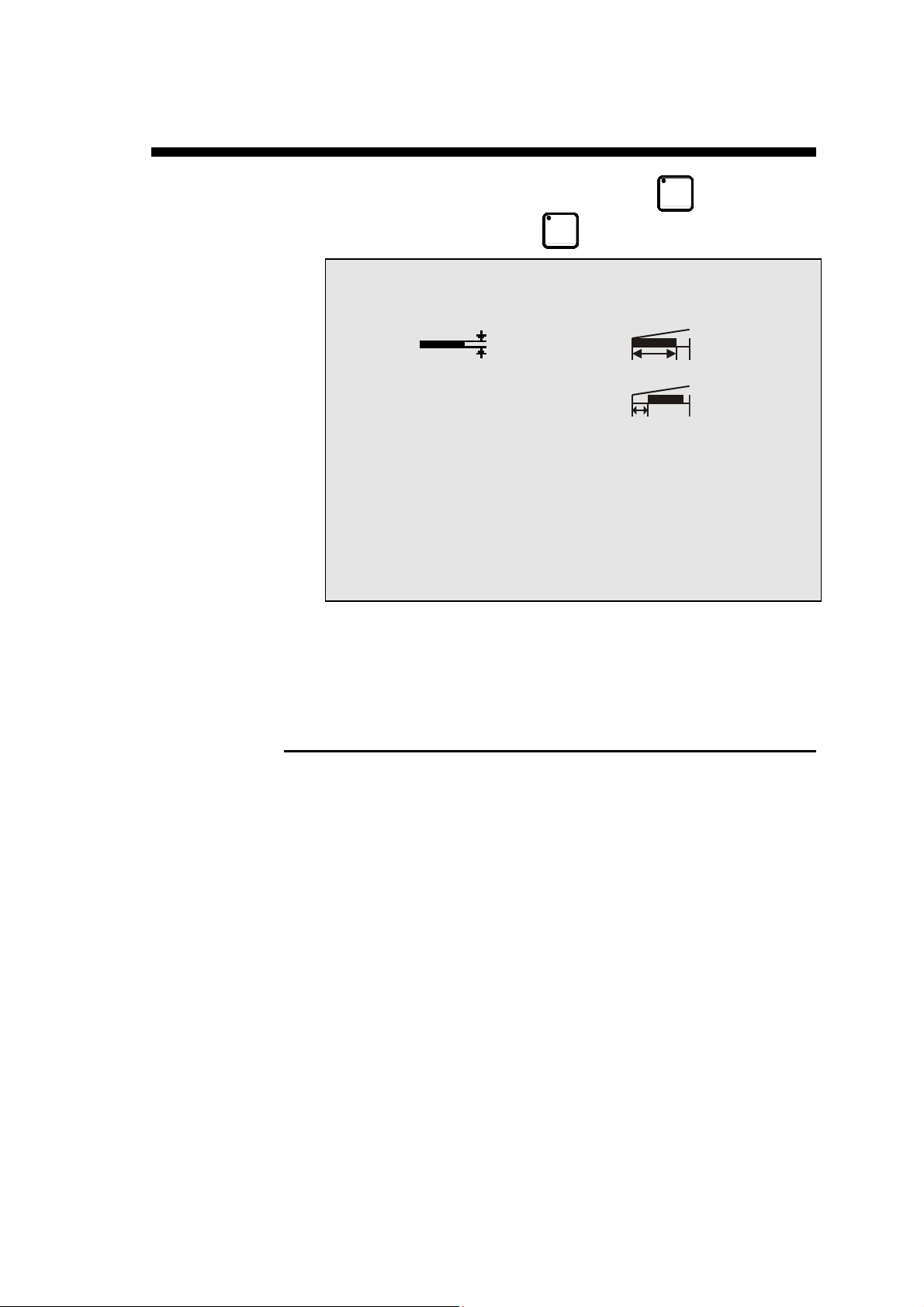
This page allows you to quickly program a cut, and/or briefly stop
production to perform a single cut without modifying or losing data in the
production program.
PROGRAMMING A CUT
Enter the thickness and the material.
Enter the distance at which the X gauge is to be positioned.
Press the START button or the pedal and the axes will position to the
desired values.
Actuate the pedal to cut.
Once the blade returns you can enter new data or actuate the pedal for a
new cut.
PAGE EASY CUT PAGE 7
Page 18

This page has been left blank intentionally.
PAGE 8 USER GUIDE DNC 60 G16
Page 19
PROGRAMMING A PRODUCT
OPERATING PROCEDURE
Enter the data
Test the product
Correct the product (if necessary) using the COR. page
Store (optional) the product
Begin production
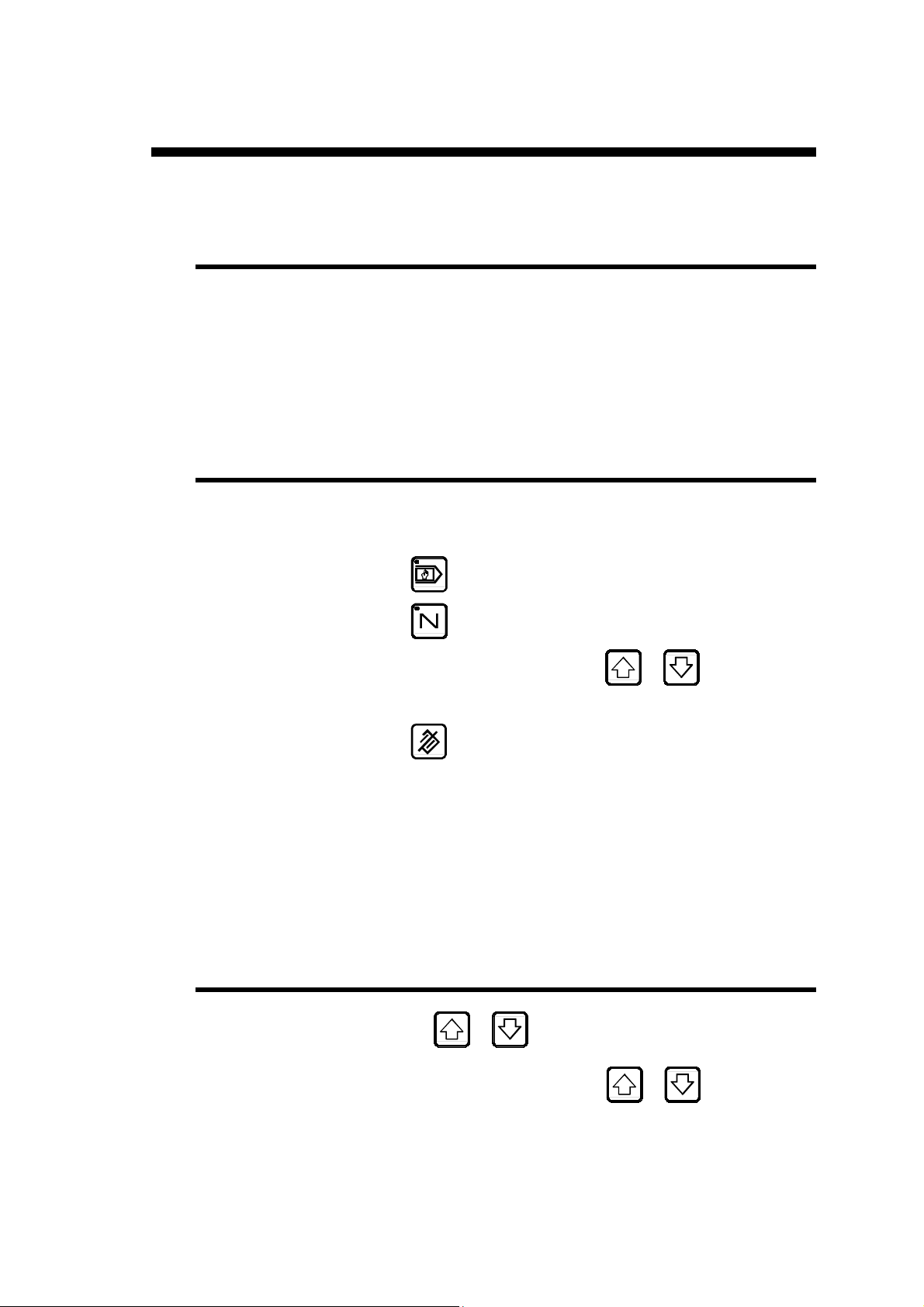
CLEARING THE BUFFER
To enter a new program into the buffer (work memory) it is best to clear
its contents before entering new data:
Press
Press
Place the cursor on N field using the
Enter the value 99.
Press
The DNC should now display the message FREE in the interactive field
at the top right of the screen.
In the Material field, the DNC should display the 1st material defined in
the machine parameters. In the Thickness field, the DNC should display
the default thickness.
to set the DNC in programming mode.
to select the sequence page.
to clear the buffer (work memory).
PROGRAMMING A SEQUENCE
or keys.
Press the or key to place the cursor on the next
programmable field.
Enter the desired value and press the
and move on to the next field.
PROGRAMMING A PRODUCT PAGE 9
or key to validate
Page 20
CREATING A SECOND (OR NTH) SEQUENCE
Press the key at the end of the program to add a sequence.
Note: when the
program.
The DNC displays the message COPIED and the number in the N field is
incremented by 1. The DNC has now created a sequence identical to the
previous one.
Enter the desired values for the new sequence.
Repeat the procedure to add a new a new sequence.
At this point you can test the product in
mode and make any necessary corrections.
The product has not as yet received a number; it will receive a number when
it is stored in the memory (see the Storage and recall of programs in the
internal memory paragraph below).
key lights up, this indicates the last sequence of the
SEARCHING FOR A SEQUENCE
Place the cursor on the N field.
Enter the number of the sequence to be found.
mode or directly in
Press the
DELETING A SEQUENCE
Place the cursor on the N field.
Enter the number of the sequence to be deleted.
Press the
Press the
This operation automatically restructures (renumbers) the remaining sequences
of the product.
key.
key.
key.
PAGE 10 USER GUIDE DNC 60 G16
Page 21
INSERTING A SEQUENCE
Inserting a sequence (with automatic re-numbering of the product
sequences):
Select the sequence after which you want to insert a new sequence
(
Place the cursor on the N field.
Press the
The DNC creates a copy of the selected sequence and places it just
after the selected sequence.
Enter the desired values for the new sequence.
Inserting a sequence by transferring an existing sequence.
Search for the sequence to be inserted.
Place the cursor on the N field.
Enter the number of the sequence where the new sequence is to be
inserted.
Press the
JUMPING A SEQUENCE
...).
key.
key.
Enter 0 in the CY field.
REPEATING A SEQUENCE
Enter the desired number of repetitions the CY field.
If the CY field is empty, the sequence is executed only once (identical to
CY = 1).
REPEATING A GROUP OF SEQUENCES
Select the last sequence of the group to be repeated.
In the JS field, enter the number of the first sequence of the group.
In the FOIS field, enter the number of repetitions minus one un it.
PROGRAMMING A PRODUCT PAGE 11
Page 22
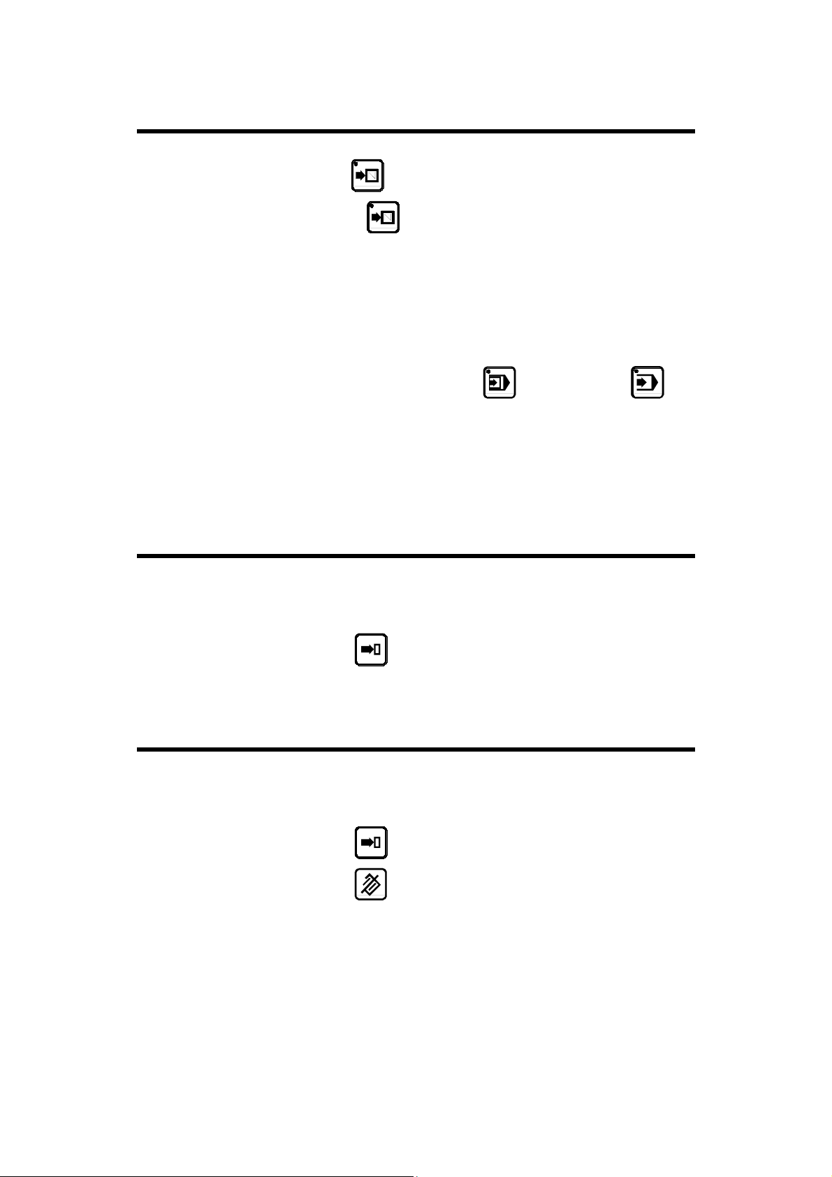
SAVING AND SEARCHING FOR PROGRAMS IN THE
INTERNAL MEMORY
Searching, saving and deleting products can only be performed in the
mode.
The field concerned is the PRODUCT field found on the top left of most
pages.
When this field exists, products can be searched for, saved and deleted
directly from this field.
SAVING A PRODUCT
A created (and tested) product can be saved for future use.
Choose an unused product number.
Place the cursor on the PRODUCT field, enter the chosen number
and press the
The message STORED is displayed once the product is saved.
key.
If the message EXISTS appears, it means that the chosen number is
already used by another program. In this case you must choose another
number.
Note: The number under which the product is to be saved must be
programmed last in the PRODUCT field, just before pressing the
Otherwise, when the cursor leaves the field, the previous value is displayed.
All other data must be entered before saving the product.
RECALLING A PRODUCT FROM THE INTERNAL
MEMORY
Place the cursor on the PRODUCT field
Enter the number of the product to be found and press the
The recalled program automatically replaces the program already in the
buffer.
The replaced program can only be recovered if it was saved beforehand.
key.
key.
PAGE 12 USER GUIDE DNC 60 G16
Page 23
DELETION OF A PRODUCT FROM THE INTERNAL
MEMORY
Place the cursor on the PRODUCT field.
Enter the number of the product to be deleted.
Press the
The interactive field displays DELETED.
If the product does not exist the message IGNORE is displayed.
key.
COMPLETE CLEARANCE OF THE INTERNAL MEMORY
Place the cursor on the PRODUCT field.
Enter the value 999.
Press the
The DNC displays DELETED.
key.
MODIFYING A PROGRAM IN THE INTERNAL MEMORY
Recall the program to be corrected as explained above.
Modify the program.
Delete the former program by placing the cursor on the PRODUCT
field and pressing the
Enter the new program by pressing the
key.
key.
PROGRAMMING A PRODUCT PAGE 13
Page 24

This page has been left blank intentionally.
PAGE 14 USER GUIDE DNC 60 G16
Page 25
DESCRIPTION OF THE NUMERICAL CONTROL
DNC
60 G16
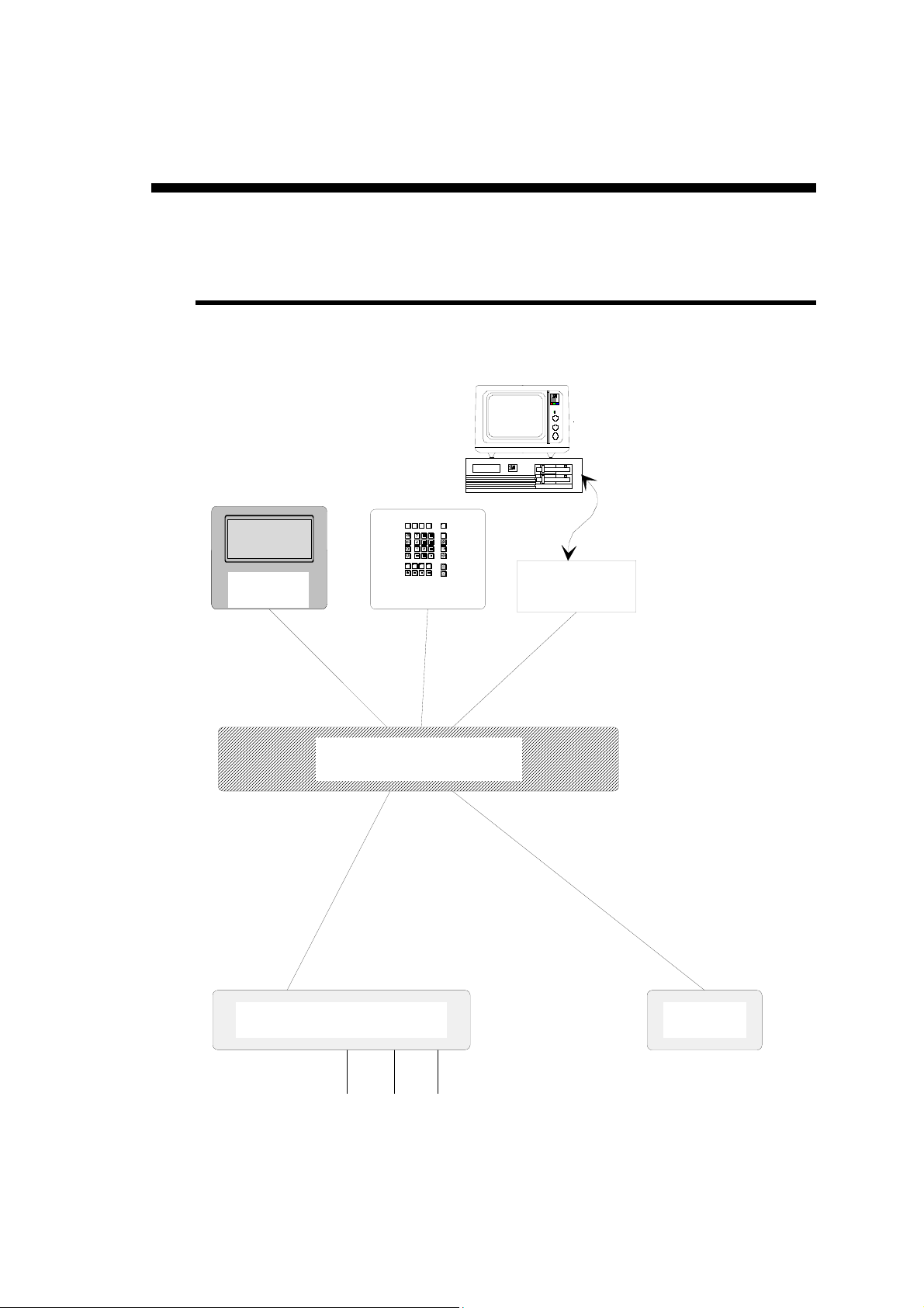
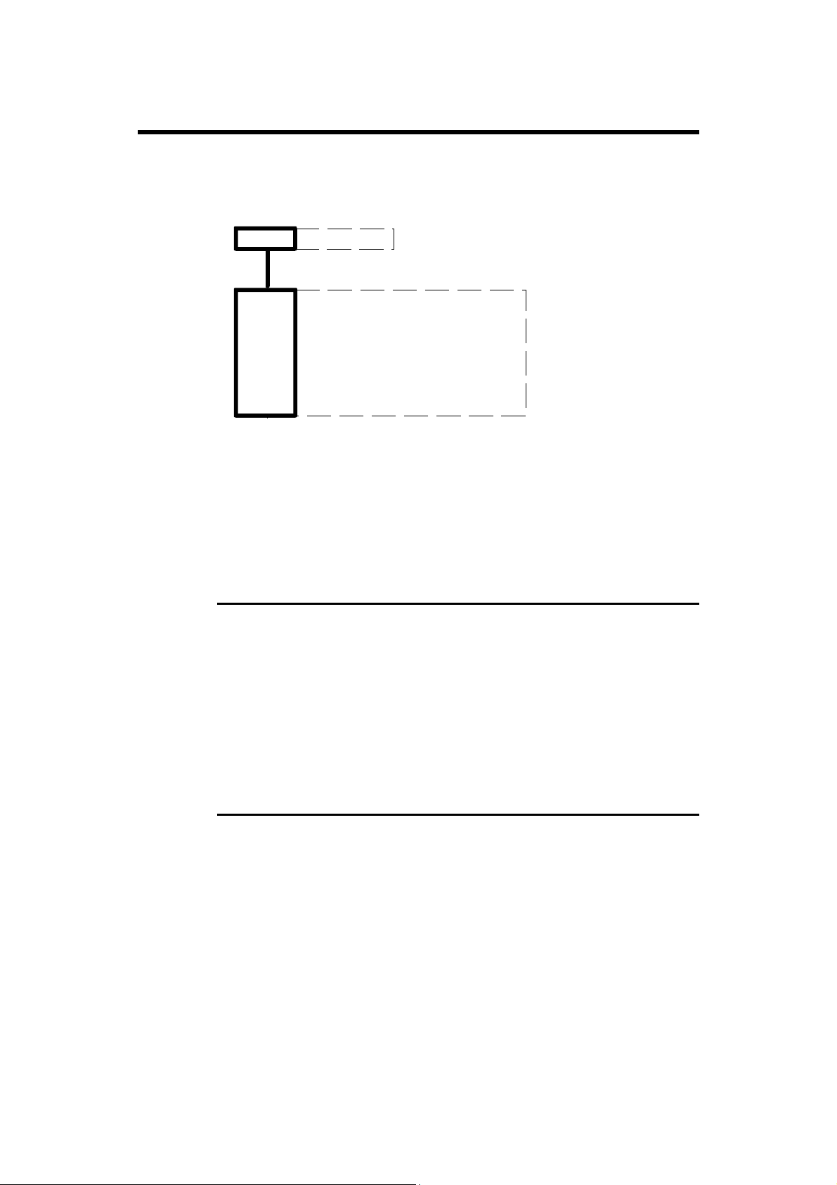
PHYSICAL AND LOGICAL ORGANIZATION
The following diagram is a schematic representation of the physical and logical organization of
the DNC 60.
RS232
Screen Keyboard
interface
Axes command and
surveillance
Motors
encoders
Microprocessors, memory
PCBs
Auxiliairy
functions
DESCRIPTION OF THE DNC 60 G16 PAGE 15
Page 26
THE MEMORIES
The different memories of the DNC 60 can be represented schematically as
follows:
ROM
RAM
+
battery
The DNC 60 is equipped with a ROM memory containing the DNC 60
program and a RAM memory, which allows the programming and saving of
products and machine parameters.
The RAM is divided into several zones each having a different use.
Program
Work memory
Internal no n vola t i le memory
Products, production,
machine parameters,
axes position
WORK MEMORY (BUFFER MEMORY)
This is a static RAM used for programming, modifying and executing
products.
It is a temporary memory containing data which is deleted whenever another
product is called for.
The content of this memory is kept if the DNC power supply is cut, even if it
has not been previously saved in the internal memory.
DNC INTERNAL MEMORY
This non-volatile internal memory, of the static RAM type maintained by a
lithium battery, contains the products, axes positions and numbers
concerning the production and machine parameters.
No programming or modifications are made directly in this memory.
PAGE 16 USER GUIDE DNC 60 G16
Page 27
THE USER INTERFACE
THE SCREEN
The screen displays the products and machine parameters as well as all other
useful information for programming and machine work.
The keys located on the front of the DNC 60 are used for selecting the screen
pages and entering data.
A cursor indicates where the user can intervene.
THE KEYBOARD
The keyboard is divided into several zones:
a) Numerical keyboard
b) Screen page selection keys
c) Working mode selection keys
d) The control keys
e) The cursor keys
f) Other keys
a) Numerical keyboard:
The numerical keys as well as the
numbers or values into the different fields.
b) The screen page selection keys:
MENU key:
Double function key.
Pressing the key once opens the EASY CUT
page.
Pressing the key a second time displays the
MAIN MENU page.
PRODUCT LIST key:
Pressing this key displays the list of products
in the DNC memory.
PRODUCT key:
Visualization of the product data (sequence 0)
and shear functions.
SEQUENCE key:
Triple function key.
Pressing the key once displays all the values of
the current sequence.
Pressing the key a second time displays the
main values of the sequences and axes in large
characters.
Pressing a third time displays the main values
of the sequence with the secondary values of
the axes in large characters.
and keys are used to enter
DESCRIPTION OF THE DNC 60 G16 PAGE 17
Page 28
CORRECTION key:
This key displays the correction page which
allows corrections to be made to the current
sequence, as well as to the entire product.
c) The working modes
PROGRAMMING mode:
Allows you to enter, modify and read data.
Allows you to save, search for and transfer
programs.
Pressing the
button or pedal will
automatically switch the DNC to automatic
mode and start the axes and functions.
MANUAL mode:
Allows axis movement and auxiliary functions
using the
keys.
SEMI-AUTOMATIC mode:
Allows a machine cycle with the current
sequence values without automatic sequence
changes.
This mode is used to make adjustments while
producing the first product, as well as for
products with only one cut.
The sequence change is made using the
keys.
Note: The product counter Q does not
function in this mode.
AUTOMATIC mode:
Standard product production mode.
The DNC automatically changes sequence
after each cut.
Changing directly from "programming" mode
automatically forces the first sequence of the
program.
Changing from "programming" mode to "semiautomatic" mode, and then to "automatic"
mode, keeps the current sequence for
execution.
This allows you to pick up the production of a
product without having to make "empty"
cycles.
PAGE 18 USER GUIDE DNC 60 G16
Page 29

d) The controls
DELETE key:
Allows you to delete a sequence or a program
when the cursor is placed on the PRODUCT
or N fields.
Only possible in PROGRAMMING mode.
CLEAR key:
This key allows you to delete data selected by
the cursor.
Pressing this key twice, on most pages, deletes
all the data on the page.
SEARCH key:
According to the cursor position, this key
allows you to:
- search for a product
- search for a sequence
- search for a screen page
- execute a transfer
Only possible in PROGRAMMING mode.
STORE (save) key:
According to the cursor position, this key
allows you to:
- save the current program in the DNC
internal memory
- create (insert) a new sequence into an
existing program
- copy (teach) the value of an axis positioned
manually in the current sequence.
This key is only valid in programming
(saving and inserting) mode and in manual
(teach) mode.
DESCRIPTION OF THE DNC 60 G16 PAGE 19
Page 30
e) The cursor keys
NEXT SEQUENCE/PAGE key:
This key allows you to scroll trough pages of
the same type. It also allows you to display the
next page when a series of information is on
several pages.
E.g.: program sequence
production pages
parameter pages
In PROGRAMMING mode, this key also
allows you to create an identical sequence
(copy function) to the previous one as long as
the last sequence of the program is selected.
The incorporated LED indicates whether the
sequence is the last of the program.
PREVIOUS SEQUENCE/PAGE key:
Allows you to scroll back through pages of the
same type.
Works in all modes except in automatic mode.
f) Other keys
Cursor up, to the next accessible field.
Cursor down, to the next accessible field.
START key:
Controls:
The movement of the axis and auxiliary
functions.
During movement the LED lights up.
An indexation (optional, depending on the
configuration) of digital axes, when this key
is first pressed after switching on the DNC.
To indicate that an index is being taken the
LED remains on until the indexes are received.
Indexes can only be taken in
or
modes.
STOP key:
Depending on the selected work mode, this key
stops the axes or auxiliary functions that are in
movement.
The Stop LED will remain on until you press
it a second time.
NB: No axes (or auxiliary function) movement
will be authorized unless the stop LED is
off.
PAGE 20 USER GUIDE DNC 60 G16
In this group of other keys, you will also find
all the movement keys connected to the
MANUAL mode.
Page 31

PRESENTATION OF THE SCREEN PAGES
CURSOR ACCESSIBLE FIELDS
By default, the cursor is located on the programmable field on which it was
placed during the last intervention on that page.
The cursor can be moved to the previous or following fields by pressing the
or key.
Regardless of the cursor position on the page, pressing the
keys simultaneously moves the cursor to the first programmable field
on the page.
When the cursor is placed on a field, you can:
introduce a number or value using the numerical keyboard.
delete the contents using the
(Important: on certain pages, pressing the
programmable fields on the page).
key.
key twice can delete all the
and the
DESCRIPTION OF THE DNC 60 G16 PAGE 21
Page 32

This page has been left blank intentionally.
PAGE 22 USER GUIDE DNC 60 G16
Page 33

THE SCREEN PAGES
THE MENU PAGE
Press the key twice to access the Menu page..
CHOICE ? 7 STOPPED
1 DATA LINK RS232
2 DISPLAY AXES
3 DISPLAY AF
4 DISPLAY CY/JS/TI
5 MACHINE MESSAGES
6 PROGRAMMING AXES DATUM
7 PROGRAMMING MACHINE PARAMETERS
To select one of the pages listed on the screen, enter its corresponding
number in the margin. Your choice is displayed in the CHOICE?__ field.
Press the
All the pages can be displayed from any mode, but it is only possible to
program in the PROGRAMMING mode.
key to display the page.
THE SCREEN PAGES PAGE 23
Page 34

THE EASYCUT PAGE
When starting, you reach directly this page, if the value of PM57 is not 0.
To open this page, press the
key.
EASY CUT STOPPED
STL
____
2.00 1000
X _____.__
ACTUAL _____ __
EASY OPT:_
Q 0
This page allows to perform individual cuts with simplified
programming.
You can momentarily interrupt the execution of a series of
programmed products in order to make a quick cut from this page.
You can then pick up the series of programmed products where it was
stopped.
When you reach this page:
- the cutting width is not defined,
- the quantity of products is initialized at 0.
The
the machine and the sheet (its availability depends on the machine
type) (see Functionalities, Offset of sheet origin).
field represents the distance between the left edge of
PAGE 24 USER GUIDE DNC 60 G16
Page 35

Flying cut in EasyCut mode
A flying cut can be performed in the EasyCut mode. To do so, an external
switch on the electrical cabinet allows you to activate or deactivate the flying
cut mode (if configured by the manufacturer).
1. The Flying cut switch is in set to ON: the AF4 field is displayed
and its value is undefined.
This field must contain a value between 1 and 9 in order to activate
the flying cut.
This value corresponds to the time spent at the TDC before the blade
starts moving again.
2. The Flying cut switch is set to OFF: the AF4 field is not displayed
and the flying cut is not active.
Note:
For safety reasons, when releasing the foot pedal, the AF4 field is reinitialized with an undefined value and the flying cut is deactivated.
THE SCREEN PAGES PAGE 25
Page 36

LIST OF PRODUCTS IN THE INTERNAL MEMORY
Press the key to access the list of products page.
PRODUCT 4 NEXT PROD.___ N 1 STOPPED
CODE
SEQUENCES N: PROG: 16 FREE: 832
--LIST OF PRODUCTS--
1 2 3 4 ___ ___ ___ ___ ___ ___
___ ___ ___ ___ ___ ___ ___ ___ ___ ___
___ ___ ___ ___ ___ ___ ___ ___ ___ ___
___ ___ ___ ___ ___ ___ ___ ___ ___ ___
___ ___ ___ ___ ___ ___ ___ ___ ___ ___
___ ___ ___ ___ ___ ___ ___ ___ ___ ___
___ ___ ___ ___ ___ ___ ___ ___ ___ ___
This page is only used to display the internal memory contents and
mention the number of programmed sequences, as well as the number
of sequences still available.
If this page is full, another page is automatically created, which can
be displayed by pressing the
It is not possible to program in the list of products.
The PRODUCT__ and CODE__ fields are only there as reminders of
the number of the product currently in the work buffer.
To store the product currently in the product buffer, press the
key.
To recall a product saved in the internal memory; select the number
and enter it in the PRODUCT field, then press the
To delete a product in the internal memory, select the number and
enter it in the PRODUCT field, then press the
To clear the whole internal memory, enter the value 999 in the
key.
key.
key.
PRODUCT field, then press the
PAGE 26 USER GUIDE DNC 60 G16
key.
Page 37

LIST OF PRODUCTS ACCORDING CRITERIA
Press the key to search in the internal memory for a product number
according to one or more of the criteria mentioned.
PRODUCT 4 NEXT PROD.__ N 1 STOPPED
CODE
THICKNESS RAKE ANGLE
3.00 __.__°
-- LIST OF PRODUCTS ACCORDING CRITERIA - 1
2
3
4
___
___
___
___
___
___
Example: Searching for a product according to its code number.
Place the cursor on the CODE__ field.
Enter the desired code number, and clear the other fields.
Press the SEARCH key
If the product exists, it is displayed in the PRODUCT column with its
code number.
If it does not exist, or the number or value is badly entered and or
incorrect, the DNC indicates IGNORE in the interactive field (top
right).
The search is performed according to the entered criteria, and
according to their values.
Any error in the entered data prevents the DNC from finding the
required product.
.
THE SCREEN PAGES PAGE 27
Page 38

DATA LINK RS232 PAGE
Choice 1 of the main menu.
The DNC 60 allows you to transfer data from or to a PC.
DNC <–> PC TRANSFER PAGE
This page allows data to be transferred to an IBM, XT, AT or compatible PC
from a RS 232 serial line.
You can transfer all the products, or just isolated products.
For a transfer to an IBM PC by serial line, the DNC 60 must be equipped
with a RS232 serial link, and the PC must be equipped with the CYBACK
type PC storage software or any other software complying with the
transmission protocol of the DNC.
DNC <-> PC STATUS STOP PA
TRANSFER 11 1 DNC --> PC
2 PC --> DNC
3,4 DATA LINK TEST 1 2
7 FLASH
8 EXT KEYBD
10 ARDIS CONNECTION
11 INTERNAL BACKUP
12 INTERNAL RESTORE
Quantity of free backup memory 93 %
-- RS232 PARAMETERS - Baud rate 57600 Stop 1.0
Parity odd (1) EVEN (0) _ Bits 8
The transmission procedure DNC <–> PC is described on page 45.
PAGE 28 USER GUIDE DNC 60 G16
Page 39

PRODUCT PAGE (AF INFORMATION)
Press the key to access the product page for auxiliary functions .
P 0 N 1 CY__
ALU1 2.00
STOPPED
____
0.74°
1000
TDC 54 0.24
BDC 39 PRESS 60
This page displays information relating to the auxiliary functions (AF)
specific to shears (blade gap, rake angle, cutting depth).
The information displayed is: - the material
- the thickness
- the width
Here you will find the following information (calculated using the
three values mentioned above).
- the blade gap
- the rake angle
- the TDC (top dead center)
- the BDC (bottom dead center)
- the downstroke pressure
The
machine and the sheet (see Functionalities, Offset of sheet origin).
THE SCREEN PAGES PAGE 29
field displays the distance between the left edge of the
Page 40

PRODUCT PAGE
Pres the key to access the product page.
PRODUCT 0 N 1 STOPPED
NEXT PRODUCT ___
CODE
Acceleration Factor X __%
SHEET: Length Width Thickness
Untreated _____.__ _____.__ 2.00
Material ALU1
NEXT PRODUCT
CODE
Acceleration factor X
SHEET
Length Width
Thickness
Untreated
Material
This field allows you to specify the next
product to be executed.
Code number for the current product.
Same with X (backgauge or dependant
auxiliary axis).
Geometrical dimensions of the sheet (they may
be used for calculating clean cut cycles).
This field is used for the calculation of the
blade gap, rake angle and possibly the blade
disengagement TDC functions. (Figure 3).
The corresponding dimensions of the sheet
before being loaded into the machine.
This field determines the blade gap calculation
constant (programmed machine parameters)
according to the material used. This field is
only displayed if the machine has a "blade gap"
function.
To select the material, use the manual keys.
Cutting width
PAGE 30 USER GUIDE DNC 60 G16
This field is only displayed if the machine is
equipped with a "cutting depth" function.
It is the width over which the upper and lower
blades cross.
Programming this field starts the calculation of
the BDC (cutting depth, figure 3).
Page 41

Blade gap (AF1)
Rake angle (AF2)
BDC (AF3)
TDC (AF3)
Gap between the cutting blades (in 1/100) for
the sheet thickness and material chosen.
Upper blade angle. It is calculated
automatically but can also be entered manually.
This field is only displayed if the machine has
a "Rake angle" function.
Cutting depth.
The value calculated for this field corresponds
to the distance (in mm) between the right end
of the upper blade and the lower blade.
This field is only displayed if the machine has
a "Cutting depth" function. Optimum Top
Dead Centre blade disengagement. It is
calculated automatically (if rake angle is
variable) but can also be entered manually.
THE SCREEN PAGES PAGE 31
Page 42

SEQUENCES LIST PAGE
a) Choice 2 of the main menu.
This page displays the data for the sequences concerning the main axis (X).
PRODUCT 4 NEXT PROD.__ N 1 STOPPED
CODE
N --X -- V%
1 _ 200.0 __
2 _ 200.0 __
3 _ 200.0 __
4 _ ______._ __
5 _ ______._ __
6 _ ______._ __
7 _ ______._ __
8 _ ______._ __
9 _ ______._ __
10 _ ______._ __
11 _ ______._ __
12 _ ______._ __
b) Choice 3 of the main menu.
This page displays the data for the sequences concerning the auxiliary
functions (AF1–>AF8).
PRODUCT 4 NEXT PROD.__ N 1 STOPPED
CODE
-- AUXILIARY FUNCTIONS - N GAP ANGL BDC
1 0.48 97 75
2 0.48 97 50
3 0.48 97 25
4 _.__ ___ ___
5 _.__ ___ ___
6 _.__ ___ ___
7 _.__ ___ ___
8 _.__ ___ ___
9 _.__ ___ ___
10 _.__ ___ ___
11 _.__ ___ ___
12 _.__ ___ ___
PAGE 32 USER GUIDE DNC 60 G16
Page 43

c) Choice 4 of the main menu.
This page displays the cycle data (CY, JS, sequence type, etc.) of the
sequences.
PRODUCT 4 NEXT PROD.__ N 1 STOPPED
CODE
N CY JS NCut
1 2 __x__ _
2 __ __x__ _
3 __ __x__ _
4 __ __x__ _
5 __ __x__ _
6 __ __x__ _
7 __ __x__ _
8 __ __x__ _
9 __ __x__ _
10 __ __x__ _
11 __ __x__ _
12 __ __x__ _
The maximum number of sequences provided for this type of machine is 36.
As the screen page can only display 12 sequences, the other sequences are
displayed on the following page, which can be displayed by pressing the
key.
To go back to the previous pages, simply press
.
THE SCREEN PAGES PAGE 33
Page 44

SEQUENCE PAGE (SMALL CHARACTERS)
Press the
This page is a recapitulative of the sequences information.
key.
PRODUCT 0 N 1 CY __/__pos STOPPED
M ALU1 Th. 2.00 Sheet Nr _______
-MEM- -POS- -SPE- -COR X _ 100.0 99.8 __% ___ __
Cut width 1000
JS __x__/__ Q prod. _____ / _____
Cycle:No cut_
Retr. _ Clean.Cut _
GAP ANGL BDC
0.24 50 39
N_
This is the sequence number. It is
automatically generated when creating a
product.
CY_
CY/POS
SHEET N°
Represents the number of times a sequence is
to be repeated before moving on to the next
sequence.
_ and 1 = no repetition (i.e. only one
sequence).
0 = the sequence is not carried out.
2 to 99 = number of repetition s desired.
The number displayed in this field corresponds
to the number of repetitions already made.
This 7 digit sheet metal number can be entered
for each sequence. It is transmitted by the RS
232 at each sequence change according to a
pre-defined protocol.
PAGE 34 USER GUIDE DNC 60 G16
Page 45

Xn
If the field immediately following the axis'
denomination is clear, the value of X -MEM- is
an absolute value to be reached.
If the field is set to 1, the X will move from the
last positioning value.
This movement will be made the number of
times programmed under CY_.
It is forbidden to program a relative value for
the X movement in the No 1 sequence (the
DNC signals an error).
If the field is programmed at 2, the axis will be
placed at 0,0 at the beginning of positioning
and it will then perform an absolute positioning
of the programmed value.
SPE
COR
Speed factor (0->99%, undef. = 100%)
This field indicates the sum of the corrections
(constant and variable) of the displayed
sequence.
JS__ J for Jump and S for Sequence.
This field allows the program to jump to a
sequence, from the next sequence, to the
sequence entered into the JS field.
TIMES/POS
The first field defines the number of times the
sequence jump (programmed in JS) is to be
performed.
The POS field defines the number of times the
jump has already been performed.
NB: Programming the JS field without
defining the number of times will result in
an unconditional jump of the planned
sequence. Generally a sequence previous
to the current sequence is programmed in
the JS field.
Similarly to the CY, which enables cycle
repetition, JS allows the repetition of a
group of sequences. This type of
programming can be very useful to carry
out a production with a minimum of
stock.
THE SCREEN PAGES PAGE 35
Page 46

Example: N JS TIMES
------------------------- 1 __ __
2 __ __
3 __ __
4 2 2
5 __ __
6 1 2
7 9 __
8 __ __
9 __ __
Cycle progression:
Note: In the above example, the sequence 8 is never effectuated
(unconditional jump).
Q__ The Q-MEM- is the number of products to be
made.
The product counter Q -POS- must be
validated by entering the value 0 or another
number corresponding to the number of
products already made.
Only then will the counter work.
To clear the counter, simply clear the Q-POS-
field.
A 24V signal is sent out as soon as Q -POS-
field value reaches the Q -MEM-value.
PAGE 36 USER GUIDE DNC 60 G16
Page 47

DEFINITION OF THE WORK CYCLE
The following fields define the type of work cycle to be chosen for the
current sequence.
Without cutting_
Retract_
Clean cut
Cutting width
Blade gap (AF1)
Cut (AF2)
Work cycle without any cutting.
By default (field is empty), the cycle will
retract. If the value of the field is 0, the cycle
will not retract. In all other cases the cycle will
retract.
Programming this field sends out a 24V signal
at the beginning of the sequence, in order to
open the scrap evacuation flap.
This field is only displayed if the machine is
equipped with a "cutting depth" function.
Width over which the upper and lower blades
cross.
Programming this field starts the calculation of
the BDC (cutting depth, figure 3).
If this field is left empty, the cut is made on the
total width of the machine.
Gap between the cutting blades (in 1/100) for
the chosen sheet thickness and material.
Function corresponding to the rake angle.
The value calculated in this field corresponds
to the vertical separation (in mm) between the
two ends of the upper blades. (Figure 3).
BDC (AF3)
Co
TDC
BDC
upper
blade
cutting
Cutting
engthl
Cutting depth.
The value calculated for this field corresponds
to the distance (in mm) between the right end
of the upper blade and the lower blade.
TDC
rake angle
sheet
lower
blade
BDC
Figure 3
THE SCREEN PAGES PAGE 37
Page 48

SEQUENCE PAGE (LARGE CHARACTERS), PROGRAMMING
Press the
P 0 N 1
ALU1 2.00
key to display the large characters sequence page.
STOPPED
1000
X _ 100.0
Actual 140.0
CY: 10/ 0
JS: __x__/ 0 Q _____
Cycle: No cut _
Retr. _ Clean.Cut _
This page is designed to facilitate product programming to the maximum.
Choice P (Product N°)
If applicable CY (number of repetitions)
Choice materiel
Choice thickness
Choice length
Choice speed
Choice cutting length
If applicable JS__x__ (jump and number of jump repetitions)
Choice quantity
If applicable: - No cut
- Retraction
- Clean cut
PAGE 38 USER GUIDE DNC 60 G16
Page 49

SEQUENCE PAGE (LARGE CHARACTERS), OPERATING
Press the key to display the large characters sequence page.
P 0 N 1 CY__
STOPPED
M ALU1 2.00
X
_ 100.0
99.8
1000
JS__x__/__
Q _____/_____
This page appears as soon as the work cycle begins.
It shows the state of the machine while it is working.
On this page you find:
The correct axis position underneath the programmed value.
CY: the number of repetitions already effectuated.
JS__x__: the number of jump repetitions already effectuated.
Q: the number of products already effectuated.
THE SCREEN PAGES PAGE 39
Page 50

CORRECTIONS PAGE
Press the key to open the corrections page.
PRODUCT 4 N 1 STOPPED
CODE
--CORRECTIONS--
CONSTANT VARIABLE --MEM--
X _ __._ __._ 200.0
CONSTANT
CORRECTIONS
VARIABLE
CORRECTIONS
NB: The resulting positioning value is displayed under the column -MEM-.
AXES DATUM
Choice 6 of the main menu.
This page is used to introduce or modify the origin of the main axis (X).
PRODUCT 4 STOPPED
SET MAIN AXES
X 100.0
100.0
Corrections to be applied to all sequences.
Corrections to be applied only to the specified
sequences.
Place the cursor on the desired axis field.
Enter the chosen value.
Remove the cursor from the field (
entered value.
The value is entered into the corresponding -POS- field.
The
PAGE 40 USER GUIDE DNC 60 G16
or ) to validate the
key allows you to display the auxiliary axes (X4/X5/X6).
Page 51

MACHINE PARAMETERS
Choice 7 of the main menu.
These pages display the operating parameters of the machine. They are
programmed when the machine is installed.
MACHINE PARAMETERS -02 X :X
10 Positioning speed ____.__
11 Fin approach speed __.__
12 Indexing speed ____.__
13 Manual slow speed ___.__
14 Manual high speed ____.__
15 A priori voltage __.___
16 Maximum voltage _.___
17 Minimum voltage _.___
18 Offset voltage __.___
19 SP/SN ratio __
20 Max. follow.eror __.__
21 Surveillance time _.___
22 Proportional gain _____
Displaying these pages from the menu page only allows you to see the
parameters, but not to modify them.
It is strongly recommended that you do not modify these values, unless
directed to do so by the CYBELEC company or one of its agents.
We also recommend that you keep a written copy of this data so that
technician can re-program the original values if necessary.
THE SCREEN PAGES PAGE 41
Page 52

This page has been left blank intentionally.
PAGE 42 USER GUIDE DNC 60 G16
Page 53

FUNCTIONALITIES
NIBBLING MODE
The nibbling mode allows you to cut by successive approaches, without
blade up stroking. This is typically for the cutting of wedges with a
rectangular form or disk sectors.
The nibbling mode is only active in semi-automatic mode, starting from key
1 and with the cursor placed on the CUTTING WIDTH field of the
SEQUENCE or EASYCUT pages.
When the pedal is released, the Cutting Authorization output is
deactivated (and also the pressure if AF6 is in pressure mode), the blade
stops and the message NIBBLING appears. As soon as the pedal is activated
again, the Cutting Authorization output is reactivated and the blade
continues its downstroke, and so on.
As soon as the BDC is reached, the blade moves normally upwards again. At
this moment you leave the nibbling mode and the message NIBBLING
disappears.
To rise the blade up again before the arrival on the BDC, just press one of the
manual keys
At this moment you leave the nibbling mode and the message NIBBLING
disappears.
or .
BLADE UP OUTPUT
This output is not configured by default. To be used, it must be configured by
the user. The idea is to be able to remove the cabled logic which is nor mally
found in the electrical cabinet for the upward movement of the blade.
This output is activated:
At each START or each time the pedal is pressed, if the blade is not at
the TDC Max.
Each time the blade has already moved down and has to be raised
again, that is to say:
– In normal use at the cutting end,
– At a STOP during the downstroking of the blade,
– At an incident in the course of the cycle.
This output is deactivated as soon as the blade has risen again, that is to say
at the ascending front of the TDC Max input.
FUNCTIONALITIES PAGE 43
Page 54

OFFSET OF SHEET ORIGIN
This functionality allows the sheet to be cut anywhere on the wid th of the
machine.
The OFFS field, located on the P and EASYCUT pages, represents the
distance between the left edge of the machine and the sheet.
The TDC and BDC are recalculated according to the OFFS value.
Formula used:
Formula used:
OFFS
BDC = (P50 – Cutlen – OFFS) · tg
TDC = (P50 – OFFS) * tg + E
Cutlen
P50
TDC
BDC
PAGE 44 USER GUIDE DNC 60 G16
Page 55

SHEET SUPPORT
Sheet supports are used to support the metal sheets before the hold-downs are
clamped (before shearing). They also help the sheared parts to slide down
onto a tray or stacker once they are cut.
Sheet supports can have 2 positions (1 high and 1 low) or 3 positions (1 high,
1 intermediate and 1 low).
The cycle of a sheet support starts after the hold-downs are tightened and
ends after they have been released (after the blade has reached the bottom
dead center).
(C1SupTol)
SW1
(C1SupTol)
SW2
(C2SupTol)
SW1
(C3SupTol)
SW2
(C2SupTol)
SW3
Position 1
Position 1
o
i
it
s
o
P
2
n
Positio
Posi
n
2
n
io
t
3
SHEET SUPPORT PAGE 45
Page 56

SCREEN DISPLAY (FOR THE OPERATOR)
This icon appears on the operator screen whenever the SupTol
field is available, i.e. whenever a sheet support is configured
on your DNC.
The value in this field only applies to the current sequence and
may change at every sequence.
To activate the sheet support for a given sequence, enter the
value 1 in this field. To de-activate it, enter the value 0 or leave
the field empty.
Whenever it is activated in a sequence, the sheet support rises to the upper
position at the beginning of the sequence.
If it isn't activated, the sheet support goes down to the lower position at the
beginning of the sequence and stays down for the entire duration of the
sequence.
MANUAL MODE
When the cursor is on the SupTol field, pressing on one of the following
keys
To stop the support at any time, simply release the key.
When the cursor is placed on the Cut width field, pressing on
down. However, pressing on
sheet support.
or on will cause both the blade and the sheet support to go
ANTI-TWIST DEVICE
An anti-twist device is a piece of equipment that will prevent the sheet from
twisting when cutting long pieces of metal.
When you start cutting, the device is in high position and holds up the metal
sheet. It is then lowered to support the sheet during cutting.
will cause the sheet support to go up or down.
or on won’t have any effect on the
SCREEN DISPLAY (FOR THE OPERATOR)
The 'A-TW' field appears on the sequence and EASY CUT pages whenever
the anti-twist feature is activated
To set the anti-twist feature, enter the value 1 in the field.
PAGE 46 USER GUIDE DNC 60 G16
Page 57

MANUAL MODE
Pressing one of the following keys
placed on the A-TW field will cause the anti-twist device to go up or down.
To stop the device at any time, simply release the key.
with the cursor
TRANSMISSION PAGE 47
Page 58

TRANSFER
To transfer data to an IBM PC by serial line, the DNC 60 must be equipped
with the RS232option.
Backup The PC must be equipped with the CYBACK storage software.
CYBACK allows you to make a backup of the data in the DNC without any
incidence on the data on the PC's level.
Updating Easy, practical and very rapid, this possibility facilitates (if necessary) the
updating of the DNC software in the FLASH memory.
The PC must be equipped with the updating software.
From the main menu page, open the TRANSFER DNC <–> PC
page.
DNC <-> PC STATUS STOP PA
TRANSFER 11 1 DNC --> PC
2 PC --> DNC
3,4 DATA LINK TEST 1 2
7 FLASH
8 EXT KEYBD
10 ARDIS CONNECTION
11 INTERNAL BACKUP
12 INTERNAL RESTORE
Quantity of free backup memory 93 %
-- RS232 PARAMETERS - Baud rate 57600 Stop 1.0
Parity odd (1) EVEN (0) _ Bits 8
Who controls ? This page will only be used to initialize the transfer type. It is not possible to
start the transfer from the DNC, this will always be done from the PC.
TRANSFER Allows you to select the type of transmission.
DNC PC Initializes the transmission PC-DNC. Mode 1 or
2 can be selected indifferently.
DATA LINK TEST Selects the test mode of the serial ports.
See the following chapter.
FLASH Prepares the DNC for the update.
EXT KEYBD Puts the DNC in external terminal mode.
See the concerned chapter.
ARDIS CONNECTION Sends the necessary values for cutting to the
DNC via RS232.
CHOICE This field allows you to select the objects to be
transferred.
In the case of option 6, PRODUCTS N°, the
last fields of the page must contain the numbers
of the products to be transferred.
PAGE 48 USER GUIDE DNC 60 G16
Page 59

TESTING THE SERIAL PORT
The serial port of the DNC 60 is the SUB-D 9P, plug J5.
Make sure that the transfer parameters are entered as follows:
PARAMETERS RS232 / DIVERS
. . .
-- COMPUTER LINK – 106 BAUD RATE 4800 STOP 1.0
PARITY ODD(1) EVEN(2) _ BITS 8
PROTOCOLE _ BCC ___
Set a test loopback connector on the serial line connector RS232 to be
tested.
Press the
The message RUN should flash.
To stop the test, press the
You can also test the transfer cable:
Connect the transfer cable to the DNC and fit a short circuiting
loopback connector on the other end of the cable to be tested.
key to start the test.
(STOP) key.
Test loopback connector
Pin 2 (RXD) wired to pin 3 (TXD)
Pin 4 (DTR) wired to pin 6 (DSR)
Pin 7 (RTS) wired to pin 8 (CTS)
TRANSMISSION PAGE 49
Page 60

CYBACK
RS 232 transmission cable
Shield: connection on the metallic hood
For this program, the RS cable must be connected to the RS232 port of the J5
plug.
The transfer parameters must be entered into the DNC, make sure that you
enter the same parameters as in the previous section (see above).
The same parameters must also be entered into the PC.
If the transfer runs at 4800 baud, you can try to increase the transmission rate
to 9600 baud.
The RS 232 norm imposes that the transfer distance be no more be then 15m
. If the distance is longer, this may affect the quality of the transfer and you
will have to decrease the transfer rate.
Reminder: The transfer command can only be given from the side of the PC.
To perform the serial transmission with CYBACK:
Set to programming mode.
Display the TRANSFER DNC <–> PC page.
Enter the value 2 into the TRANSFER field.
Press the
The display indicates STATUS RS232.
Programming mode The DNC can now receive data sent from the PC, provided that the DNC is
in programming mode.
In the other modes (auto, semi-auto or manual), the DNC doesn't respond and
the transmission is therefore not accepted.
During the transmission, the operator can leave the DNC on any page. It is
not necessary to display the transfer page.
The transfer mode remains memorized, even if the DNC is disconnected
from the power supply. It has to be re-programmed however if the mode is
changed (for instance to FLASH).
key.
PAGE 50 USER GUIDE DNC 60 G16
Page 61

This page has been left blank intentionally.
TRANSMISSION PAGE 51
Page 62

PROTECTING ACCESS LEVELS
GENERAL INFORMATION
The DNC 60 has four access levels.
Depending on the version, the DNC 60 can or cannot be equipped with a
4-position key switch.
If the DNC 60 is not equipped with a switch key, the access is protected by
password.
IMPORTANT
initialization of the machine parameters (817 on INIT page and Choice Init
Mach Par = 1).
In this manual we always will speak of a (virtual) key position, e.g.: "Key in
position 3".
Levels There are 4 access levels, 0 to 3:
0 = Programming is prohibited.
1 = Creation, correction, modification, saving, deleting, transfer of one
2 = Creation, correction, modification, saving, deleting, transfer of the
3 = Programming, modification and transfer of the machine parameters.
Access These levels are accessed by pressing the
A pop-up is displayed.
Press the
The key position is displayed as a number on the upper right part of the
screen (after the interactive field).
When passing to a higher access level, a new password will be requested.
When the password has been entered, you can access levels inferior or equal
to the authorized one, without reentering the password.
Passing to level 0 resets the password validity.
: passwords will be reset to the default values at each
(or more) product(s).
tools.
or keys to enter your password.
(STOP) key for two seconds.
Users A number of different users are predefined. A user is not a particular
individual, but can for example correspond to all the operators having the
authorization to work on the machine.
Each predefined user has a password and a maximum level which can be
reached. See the Table of users, access and passwords section.
Password Certain users can modify their own password. For the others, the password
can only be changed by a user having a superior access level.
Loss of the password If the password is lost, a user of a superior access level has to reprogram the
password.
PAGE 52 USER GUIDE DNC 60 G16
Page 63

THE USERS
Table of users, access and passwords.
Level Names of
predefined
users
1
2
3
4 WSSUPER OK OK 3 Workshop supervisor
5 MACHMAN NO OK 3 Machine manufacturer's
6 MACHMAN0 OK OK 3 Machine manufacturer’s
A predefined user is just a role.
Many physical persons can have the same role. E.g., many physical operators can be a EUL1 (level 1).
After installing the machine it is recommended that the password by default of level 4 (WSSUPER =
Workshop supervisor) and of level 3 (EUL3 = Operators with authorization level 3) be modified, simply
because the passwords are in this manual.
EUL1 NO NO
EUL2 NO NO
EUL3 NO NO
Changing of
the personal
password
Changing of
passwords of
the
subordinates
Level
virtual key
1
2
3
Password
by default
111 Operators with access
222 Operators with access
Operators with access
User generally attributed to:
authorization to level 1
authorization to level 2
authorization to level 3
Service technicians
technician manager.
PROTECTION OF ACCESS LEVELS PAGE 53
Page 64

ACCESS BY PASSWORD
Upon starting the software, the virtual key is always positioned at 0.
Press the
Choose the level to access by pressing the
keys.
The message VALUE ? appears.
Enter the password and press the
The message OK and the selected level are displayed if the password
is accepted, or KO if it is refused.
Once the authorization is granted, the operator can change levels according
to his accessibility, without entering a new password.. For instance, a user
with access on level 3 can navigate between levels 1, 2 and 3 without having
to enter the password again.
If level 0 is activated, a password will be required to access any other level.
This password will also be requested when the user passes to a superior level
(from 0 to 1, from 1 to 2, from 2 to 3, etc.) and does not have access with the
current password.
Advice If you have access to level 3, access level 0 after your intervention. This will
avoid making unwanted changes by mistake.
key for two seconds.
, or
key to validate the password.
PAGE 54 USER GUIDE DNC 60 G16
Page 65

ACCESS TO LEVELS SUPERIOR TO 3
Certain users can access levels superior to 3. This allows them, among other
things, to modify passwords.
To find out more about the various authorizations, see Table of users, access
and passwords.
Press the
A pop-up is displayed.
The message LEVEL ? appears.
Type the access level you want to access.
The message VALUE ? appears.
Enter the password corresponding to the requested access level and
validate with the
The DNC passes to level 1. The operator can "navigate" between
levels 1 and 3 without reintroducing his password.
At the end of the intervention, don't forget to pass to level 0 in order
to leave the current access level.
key for two seconds.
key. Press the
key.
PROTECTION OF ACCESS LEVELS PAGE 55
Page 66

CHANGE PASSWORD
This allows some users to modify the passwords attributed by default.
Certain users can do it for themselves, others cannot. In order to know the
authorizations, see Table of users, access and passwords.
To change a password:
Press the
A pop-up is displayed.
Press the
The message LEVEL ? appears.
Type the access level number you want to access.
The message VALUE ? appears.
Enter the password corresponding to the requested level and validate
with the
Press the
A pop-up is displayed.
Press the
The message LEVEL ? appears.
Program the access level for which you want to modify the password.
The message IGNORE appears if the requested level is superior to the
accessed level. If not, the message VALUE ? appears.
key for 2 seconds.
key.
key.
keys for two seconds.
key.
Enter the desired new password and validate with the
The message CONFIRM appears.
Enter the new password again and validate with the
If the two registered passwords are identical, the message OK is
displayed.
If the two registered passwords are different, the user is invited to
introduce the 2 passwords again, the message VALUE is displayed.
At the end of the procedure, don't forget to pass to level 0 in order to
leave the current level.
PAGE 56 USER GUIDE DNC 60 G16
key.
key.
Page 67

This page has been left blank intentionally.
PROTECTION OF ACCESS LEVELS PAGE 57
Page 68

MAINTENANCE
IN CASE OF FAILURE
INITIAL CHECKS TO BE CARRIED OUT
Switch the machine off then on again.
Check the program (safety factors).
Check that the axes can be moved in manual mode.
Compare the machine parameters to those on the written list made
during the installation.
Check the power supply voltages (to do this please refer to the
technical manual).
Check that the keyboard responds.
Check that the front panel lamps light up.
POSSIBLE MEMORY POLLUTION
After performing the initial checks above, it is then likely that you have a
memory pollution problem. To locate the fault, proceed as follows:
Switch off the DNC.
Switch on the DNC.
Follow the instructions in the next chapter The Initialization page.
PAGE 58 USER GUIDE DNC 60 G16
Page 69

THE INITIALIZATION PAGE
This page appears if a calculation is impossible, due to unprogrammed data
or an incorrect value.
It can also appear as a result of pollution of one of the memory zones which
will also result in impossible calculations.
INITIALIZATION DNC 60 G
---------
--MEMORY ZONE--
_ Clear variables zone
_ Clear machine parameters zone
_ Clear transmission RS232 zone
EXECUTION CODE ___
It may be necessary to use this page intentionally in order completely clear
the data on the DNC and to re-start the programming on a "clean" basis.
To display the Initialization page, press the
If the Initialization page appears unexpectedly, proceed as follows:
Note: If point 1 does not re-establish a normal situation, go on to the next
point and so on. The following operations clear successively all the data in
the selected memories. It is therefore recommended to re-introduce the data.
1) Press the
2) Enter:
- value
- value
Press the
Press the
1 in the Clear variables zone field
817 in the EXECUTION CODE.field
key twice.
key.
key twice.
and keys.
3) Enter:
- value
- value
- value
MAINTENANCE PAGE 59
1 in the Clear variables zone field,
1 in the Clear machine parameters zone field
817 in the EXECUTION CODE field.
Page 70

Press the
Press the
4) Enter:
value
1 in the field Clear variables zone,
1 in the field Clear machine parameters zone,
value
1 in the field Clear transmission RS232 zone
value
and value
Press the
Press the
Clearing the machine parameters also deletes all the input / output
configuration defined by the operator.
We therefore recommend that the DNC 60 be re-configured before next use.
Important: If you use an external system for re-entering data (CYBACK
via RS232) and the problem persists, then the information re-entered by this
system have to checked again.
The best thing to do in this case is to again delete the who le contents of the
DNC and to re-program the DNC manually via the keyboard (not the RS232
line).
key.
key twice.
817 in the field EXECUTION CODE.
key.
key twice.
BEFORE CALLING FOR TECHNICAL HELP
Please have ready the following information:
Type of numerical control.
Serial Nr of the DNC.
DNC and axes (N2X) software numbers.
Name of the machine tool's manufacturer.
List of machine parameters (have on hand when the technician
comes).
The state of the numerical control:
- which LEDs are on?
- which message is on the screen ?
Details of what caused or is causing the problem.
PAGE 60 USER GUIDE DNC 60 G16
Page 71

INTERNAL BACKUP (SAVE)
A machine parameter and tools backup is available in the internal memory. A
restoration can also be performed from this same internal memory.
This functionality is exclusively used by the manufacturer to memorize the
parameters and tools state, at the time of the delivery of the machine.
In the event of problems, this will allow the operator to easily reload the
original parameters and/or delivered tools. This can be done without
connecting the DNC to a PC.
Note: Only the last compatible backup can be restored.
The memory quantity is limited. Each save takes up memory space (no
rewrite possible) and the number of backups depends on the software version
and the number of tools.
If this memory is full, it can only be deleted by reinstalling the boot software
(See further). This is an operation which must only be done by a qualified
and trained person.The number of backup saves available (generally 1 to 2)
is enough for the correct use of this function:
Backup are usually performed:
• When the machine leaves the factory.
• When the machine is set up in workshop
• When a technician is called to re-configure a machine.
Internal backup (saving) of the PMs and tools
To save the machine parameters and tools, go to the TRANSFER RS232
page from the main menu.
DNC <-> PC STATUS STOP PA
TRANSFER 1 1 DNC --> PC
2 PC --> DNC
3,4 TEST LIAISON 1 2
7 FLASH
8 EXT KEYBOARD
10 ARDIS CONNEXION
11 INTERNAL BACKUP
12 INTERNAL RESTORE
Quantity of free backup memory 97 %
-- RS232 PARAMETERS - Baud rate 57600 Stop 1.0
Parity odd (1) EVEN (0) _ Bits 8
• Select 11 INTERNAL BACKUP
MAINTENANCE PAGE 61
Page 72

DNC <-> PC STATUS STOP PA
TRANSFER 1 1 DNC --> PC
2 PC --> DNC
3,4 TEST LIAISON 1 2
7 FLASH
8 EXT KEYBOARD
Internal backup
10 ARDIS CONNEXION
11 INTERNAL BACKUP
12 INTERNAL RESTORE
0 = Abort
1 = Save machine parameters
2 = Save tools
Quantity of free backup memory 97 %
-- RS232 PARAMETERS - Baud rate 57600 Stop 1.0
Parity odd (1) EVEN (0) _ Bits 8
• Choose the operation by pressing the 0, 1 or 2 key.
The pop-up closes.
• The message value ? is displayed at the top right of the screen (the
same as for changing to access level 2 or 3).
Enter the level 4 code for the machine parameters or the 217 code
for the tools.
• Press the
key.
DNC <-> PC STATUS EXECUTE
TRANSFERT 1 1 DNC --> PC
2 PC --> DNC
3,4 TEST LIAISON 1 2
7 FLASH
8 EXT KEYBOARD
10 ARDIS CONNEXION
11 INTERNAL BACKUP
12 INTERNAL RESTORE
Quantity of free backup memory 93 %
-- RS232 PARAMETERS - Baud rate 57600 Stop 1.0
Parity odd (1) EVEN (0) _ Bits 8
When the backup save has finished, the EXECUTE message and the new
free memory percentage are displayed.
PAGE 62
USER GUIDE DNC 60 G16
Page 73

INTERNAL RESTORATION OF PMS AND TOOLS
This functionality allows the owner of the machine to restore the original
factory parameters. This can be used in the event of problems by the
operatorm, assisted by the manufacturer/dealer.
The parameters restoration will replace the current contents of the DNC by
the last parameters save (generally performed by the manufacturer upon
machine delivery).
The tools restoration will replace all tools data which have the same number.
The tools which have a different number to those in the backup are not
affected by the restoration.
Example: The punches number s 1 and 2 have been saved.
The user has modified the data of the punches 1 and 2, and has
added the punches 12, 14 and 15.
At the moment of the restoration, the value of the data of the
punches 1 and 2 will be replaced by those of the saved tools.
The punches 12, 14 and 15 aren’t affected.
Only the last compatible backup can be restored.
To restore the machine parameters and tools, go to the TRANSFER RS232
page from the main menu.
DNC <-> PC STATUS STOP PA
TRANSFER 11 1 DNC --> PC
2 PC --> DNC
3,4 DATA LINK TEST 1 2
7 FLASH
8 EXT KEYBD
10 ARDIS CONNECTION
11 INTERNAL BACKUP
12 INTERNAL RESTORE
Quantity of free backup memory 93 %
-- RS232 PARAMETERS - Baud rate 57600 Stop 1.0
Parity odd (1) EVEN (0) _ Bits 8
• Select 12 INTERNAL RESTORE
MAINTENANCE PAGE 63
Page 74

DNC <-> PC STATUS STOP PA
TRANSFER 11 1 DNC --> PC
2 PC --> DNC
3,4 DATA LINK TEST 1 2
7 FLASH
8 EXT KEYBD
Internal restore
10 ARDIS CONNECTION
11 INTERNAL BACKUP
12 INTERNAL RESTORE
0 = Abort
1 = Restore machine parameters
2 = Restore tools
Quantity of free backup memory 93 %
-- RS232 PARAMETERS - Baud rate 57600 Stop 1.0
Parity odd (1) EVEN (0) _ Bits 8
• Select the operation to be performed by pressing the 0, 1 or 2 key.
• The pop-up closes.
• The message value ? is displayed at the top right of the screen (the
same as for changing to access level 2 or 3).
Enter the code 718 to restore the machine parameters or the tools.
• Press the
key.
DNC <-> PC STATUS STOP PA
TRANSFER 11 1 DNC --> PC
2 PC --> DNC
3,4 DATA LINK TEST 1 2
7 FLASH
8 EXT KEYBD
Restore successfully done
10 ARDIS CONNECTION
11 INTERNAL BACKUP
Press any key to continue
12 INTERNAL RESTORE
Quantity of free backup memory 93 %
-- RS232 PARAMETERS - Baud rate 57600 Stop 1.0
Parity odd (1) EVEN (0) _ Bits 8
When the restoration has finished, a pop-up is displayed.
PAGE 64 USER GUIDE DNC 60 G16
Page 75

This page has been left blank intentionally.
MAINTENANCE PAGE 65
Page 76

SAFETY AND INTERACTIVE MESSAGES
Whenever the or mode keys are pressed to try and enter into the
machine working modes, the safety systems are verified and any errors are
shown by the impossibility to pass to
The DNC forces the
concerned and the interactive field indicates ERROR.
The error must then be corrected and the passage to
tried again. If another error exists the process repeats itself until all the
programming faults have been corrected.
mode; the cursor positions itself on the field
THE INTERACTIVE MESSAGES
<– SHEET
24V down
The sheet has come out of the clamps (with
clamps closed).
Sheet blocked in the clamps (with clamps
opened).
As soon as the 24V is interrupted on the
numerical control, this message is displayed in
the interactive field.
or mode.
or mode be
ABORT
ACTIV EO
AFs Adju
BDCMax1
BDCMax2
Indicates that the transfer has been interrupted
using the STOP key of the DNC.
This message appears when you activate the
connection with Easy Optimizer.
The machine is adjusting the angle and (/or) the
gap of the blade.
The BDC Max sensor is active while the blade
is waiting to leave the TDC (sensor fault,
wiring problem, etc.)
The BDC was detected by the BDC Max
sensor, before the calculated BDC during
WaitBDC. This safety sensor is placed too high
compared to the low point of the measurement's
potentiometer.
PAGE 66 USER GUIDE DNC 60 G16
Page 77

CASSETTE
COPIED
COUPE
CUT OFF
DELETED
Indicates that the “cassette” (internal memory)
- is not initialized
- is polluted
- has changed format (ex.: while changing the
software version).
Internal memory must be cleaned. Place the
cursor on P field, introduce 999 and press the
touch.
Displayed in
mode when a new sequence
is created at the end of the program using the
key.
Displayed when the blade begins to descend
and is lower than the TDC potentiometer.
The blade position is out of the AF2 and AF3
MP limits when pressing the start key.
Displayed in
mode when a product or
DNC <–> PC
END
END P EO
ERR-AXIS
ERR-MODE
ERREU EO
ERROR
sequence is deleted using the
key.
Indicates a transfer from a DNC towards a PC.
Displayed in
or mode, indicates
the last sequence of the program.
End of the Easy Optimizer program.
Following error (theoretical trajectory).
In the case of a exterior-DNC transfer, this
message indicates that the data received is not
valid, and thus impossible to read.
Error during the transfer of data from Easy
Optimizer.
This message is indicated when a calculation is
impossible, or would create out-of-range
values.
When security measures are in force (in other
words when an axis is told to move beyond its
authorized limits).
This information is followed by a return to
mode and the cursor positions itself
automatically over the field to be corrected.
Error LS
ErrorN2X
Limit switch error.
N2X command error.
SAFETY AND INTERACTIVE MESSAGES PAGE 67
Page 78

Escam X
Esc H Dn
Esc H Up
EXECUTED
EXISTS
EXIT EO
FREE
This message appears when the programmed
distance for the X axis is greater than the
distance from the ramp.
The machine waits until the hydraulic foldaway
arrives at the DOWN point.
The machine waits until the hydraulic foldaway
arrives at the UP point.
The DNC has made the calculation correctly
(corrections, transformations, etc.).
Displayed in
mode when the product
number chosen to be saved already exists in the
cassette.
This message appears when you deactivate the
connection with Easy Optimizer.
Displayed in
mode when the buffer is
empty (no sequences programmed).
FULL
Displayed in
mode when the buffer is
full (no more space for an additional sequence).
IGNORE
Displayed when the key used cannot (must not)
be used at that time.
INACTIF
Indicates an attempt to switch to
or
mode on a sequence for which the CY is
programmed to 0.
INDEX Refers to Sheet index when the calculation of
the length is done automatically.
INDEXED
INSERTED
Machine indexing.
Indicates that the insertion has been made
correctly.
LAST
Displayed in
mode when the sequence
shown is the last of the product.
LIMIT !
PAGE 68 USER GUIDE DNC 60 G16
This message appears when the calculation of a
shears function (blade gap, rake angle, BDC or
TDC) exceeds the limits imposed by the
machine parameters.
The DNC limits the calculated value to the limit
defined in the machine parameters and positions
the cursor on the function by default.
Page 79

MachPar
Indicates that an N2X machine parameter is not
valid. You must refer to the specific N2X
manual.
MAT KO
Error: the material selected by Easy Optimizer
is not completely defined in the DNC.
MODIFY
Displayed when the operator programs the
DNC.
N2XPause
Indicates that the corresponding axis has been
temporarily PAUSED by means of the defined
input.
N CUT EO
The DNC asks Easy Optimizer to send the next
cut of the pattern.
N MAT EO
The material number in Easy optimizer doesn’t
exist in the DNC.
NO EASYC This message appears EASYCUT mode cannot
be accessed because the P57 = 2 (No
EASYCUT mode).
NEXT
Is displayed during the successive display
NO SPACE
NO-ACTIV
N PAT EO
ONLY E C
PausCycl
PC <–> DNC
key) of the sequences which exist in the
(
buffer (except for the last sequence which
indicates END).
Indicates that the product list memory has no
more space available.
Indicates an attempt to change to
or
mode on a sequence where the CY is
programmed at 0.
The DNC asks Easy Optimizer to send the next
pattern of the program.
This message appears when you can’t exit the
EASYCUT mode because P57 = 1
(EASYCUT mode only).
At rising edge the machine cycle is stopped
(interrupted). At falling edge the cycle
continues.
Indicates a transfer from a PC towards a DNC.
PositTol
One of the axes is not in the set tolerance.
PREVIOUS
Same as NEXT but with the
key.
SAFETY AND INTERACTIVE MESSAGES PAGE 69
Page 80

Recalage
RecAngle
Rec Jeu1
Rec Jeu2
Rec JeuC
Regl FA
RESTORE !
RPedale1
RPedale2
The machine is adjusting the angle and (/or) the
gap of the blade. The blade can go up step by
step before making the adjustments.
Adjustment of the blade angle (AF2 only).
Adjustment of the first blade gap (AF1 only).
Adjustment of the second blade gap (AF5
only).
Adjustment of the blade gap (AF1 and AF5
only).
The machine is adjusting the Angle (AF2) and
(/or) the Blade Gap (AF1).
Displayed when the next product is loaded in
the DNC from the exterior, for instance from a
PC.
The user has released the pedal during waiting
before leaving the TDC.
The user has released the pedal while the blade
was going down to BDC.
RPedCou1
The user has released the cutting pedal while
waiting before leaving the TDC (2 levels
pedal).
RPedCou2
The user has released the pedal while the blade
was going down to BDC (2 levels pedal).
RS232
RserTol1
Indicates a transfer from a PC towards a DNC.
The hold-down is opened before leaving the
TDC.
RserTol2
The hold-down opened while the blade was
going down to BDC.
RUN
Indicates that the transmission is being made
correctly. This message flashes slowly for the
duration of the transmission.
Start EO
When connection with Easy Optimizer is
established, this message appears when first
pressing on the Start key or the pedal.
StopCycl Indicates that the /STOPCYCLE input has
been de-activated. The current sequence will
finish and the machine will wait for a new front
panel START.
STOPPED
PAGE 70 USER GUIDE DNC 60 G16
Indicates that the machine has been stopped by
pressing the
stop key on the front panel.
Page 81

STORED
Indicates that the storage (save) operation has
been made correctly.
Synchro
The maximum authorized separation
(X1<->X2) has been exceeded.
TDCMax2
The TDC Max sensor is active while waiting
for WaitBDC signal (sensor fault, wiring
problem, …)
TDCMes2
The PMH Max sensor is active while waiting
for the WaitBDC signal (potentiometer fault,
wiring problem, …)
TEACHED The TEACH operation has been performed
correctly.
TEST
Indicates that the DNC is in communication
TEST mode.
TIME OUT
Indicates that the DNC has not received any
valid information since the beginning of the
transmission, and thus returns the command to
the operator. This message appears after about
30 seconds.
TolPosit
One axis is not in the set tolerance.
or mode,
UNDEFINED
Refusal to change to
occurs if the parameters vital to execution are
only partially programmed and thus prevent the
verification calculations.
Variat Informs that the Variator OK input is no
longer detected. The variator must be checked
for any problems.
WaitFST
Waiting for the hold-down to close ( Time or
input according to the PM36)
WaitPeda
All axes and AFs are ready for the sequence in
progress when the numerical control is in
mode. The numerical control is waiting for the
pedal.
WaitStrt
Displayed at the end of the sequence in
and
mode. Waiting for the pedal.
Wait BDC
The blade goes down, waiting for the arrival at
the BDC calculated by the DNC.
Wait TDC
The blade goes up, waiting of the arrival at the
TDC calculated by the DNC.
SAFETY AND INTERACTIVE MESSAGES PAGE 71
Page 82

WaitOST
WaSuToDn
WaSuToUp
WaTeSuTo
WpedCoup
WSuToDn1
WSuToDn2
W TDCMax
Waiting for the opening of the hold-down after
reaching the BDC and before making the
sequence advance.
The machine is waiting for the Sheet Support to
arrive at UP position.
The machine is waiting for the Sheet Support to
arrive at DOWN position.
Waiting for the temporization of the sheet
support.
Waiting for the cut pedal order, appears as soon
as the hold-down time has run out.
The machine is waiting for the Sheet Support to
arrive at DOWN position (for Sheet Support
with 3 positions, first part of DOWN).
The machine is waiting for the Sheet Support to
arrive at DOWN position. (for Sheet Support
with 3 positions, second part of DOWN).
The blade is rising. Waiting for the signal from
the TDC Max sensor.
WtempDec
WtempTDC
ZonIndex
Specific message for the AF6 in pressure mode.
Indicates the machine is waiting for the
decompression time (PM92).
Informs that a temporization is in progress
while the blade is stabilized at the TDC.
This message appears when an axis is already in
an index zone and that the N2X programming
of this axis prohibits an automatic exit from this
index zone. In this case you should refer to the
N2X user manual under parameter N° 25.
PAGE 72 USER GUIDE DNC 60 G16
Page 83

This page has been left blank intentionally.
SAFETY AND INTERACTIVE MESSAGES PAGE 73
Page 84

PRINT SCREEN TO THE PRINTER (OR ASCII FILE)
If the RS232 port is included (optional), the DNC 60 allows you to print the
content of a page displayed on the screen.
This print allows you to retain information regarding the product(s), tools or
machine parameters.
To send this information to the printer, you must use a serial printer
(RS232).
You have to set the DNC 60 transmission parameters to the printer's
required specifications:
Baud rate: 4800 max.
Bits: 7 or 8
Stop bits: 1, 2 etc.
Parity: 1 or leave blank
Protocol: this field defines how many DNC pages you want to have
on one printer's page. After choosing the relevant number,
the DNC sends a form feed character to the printer.
Example: 1 = 1 DNC page per printer page.
2 = 2 DNC pages per printer page, etc.
BCC: this field defines the left margin in cm.
left margin = 2 + (BCC x 2)
valid range: 0 (2 space characters) to 9 (20 space
characters)
Example: BCC = 4, then 2 + (4 x 2) = 10
Printing from the DNC 60:
Select the relevant page.
Simultaneously press the STOP + CORRECTION or MENU keys.
PAGE 74 USER GUIDE DNC 60 G16
Page 85

HYPERTERMINAL
CONNECTION
It is possible to send all the pages of a DNC60 onto a PC in .txt files, which
allows you to keep a hardcopy backup of the machine parameters, programs
or other DNC 60 elements.
Connect an inverted (non-modem) RS 232 cable between the J5 connector of
the DNC and the RS 232 port of the computer. In the case of a portable
computer without an RS 232 port, a USB-RS232 converter has to be used
(e.g. an Aten brand converter).
PRINT SCREEN PAGE 75
Page 86

PREPARATION
The connection parameters must be the same on the DNC as on the
HyperTerminal.
DNC 60 Parameters
PARAMETERS MACHINE -06- Ignore
---- RS232 CHARACTERISTICS
60 Transmission speed 9600
61 Data transmission 8
62 Stop bits 1.0
63 Parity (-:off, 0:even, 1:odd) _
65 Protocol 0
66 BCC 5
67 Locking calculation search K7 _
68 Inch mm conversion
69 Stop Q Part reached _
Protocol: The number of DNC pages printed on a page is
indicated in this field.
Exemple:
1 = 1 DNC page per printer page.
2 = 2 DNC pages per printer page.
If nothing is programmed, the pages are sent one
after the other.
BCC: this field defines the left margin in characters
(spaces).
Left margin= 2 + (BCC x 2)
Field: 0 (2 characters) to 9 (20 characters)
Example: BCC = 4, i.e. 2 + (4 x 2) = 10
LAfter having modified the parameters:
• Go to the TRANSFER page.
• Select 1 then hit the
new parameters, or turn the DNC off and on again.
key to confirm the transmission with the
PAGE 76 USER GUIDE DNC 60 G16
Page 87

Configuration of the HyperTerminal
• Enter a name for the file which will contain the parameter setting for
this numerical command, and choose an icon. You will call up this
file every time you connect to the numerical command without
having to reset the Hyper Terminal parameters.
• Connect via a serial port.
PRINT SCREEN PAGE 77
Page 88

• - Port parameters:
Bits per second: 9600
Data bits: 8
Parity: None
Stop bits: 1
Control flow: None
• Select properties:
PAGE 78 USER GUIDE DNC 60 G16
Page 89

• Enter the parameters as above.
• Click on the ASCII Configuration button.
• Tick the Line Word-wrap box. Then OK
• Select Display then Font
PRINT SCREEN PAGE 79
Page 90

• Choose Standard Terminal 14
ENTERING THE SCREENS
The parameters have now been set on both the DNC and the Hyper Terminal,
which have been interconnected and are ready to transmit.
• Open the Call menu,
• Select Call
• Open the Transfer menu.
• Select Text Capture.
• Select the location and name of the file which will contain the DNC
screen pages.
PAGE 80 USER GUIDE DNC 60 G16
Page 91

• On DNC 60, select the page to be printed
• Press the
• Repeat the operation for each desired page.
• Disconnect.
• The captured pages are visible in the previously selected txt file.
and keys simultaneously.
Printing out all the machine parameters
With the DNC 60 P, PC and PS, starting from the SIXFDAx version, it is
possible to print all the machine parameters in a single operation. To do th is:
• Go to the machine parameters.
• Press
,
and
simultaneously
PRINT SCREEN PAGE 81
Page 92

EASY OPTIMIZER
INFORMATION
Easy Optimizer is a cutting optimizer program for Sheets. It runs on a PC
and provides graphical solutions.
This program is very simple, quick and powerful.
The computed solutions (cutting sequences and dimensions) may be printed
or sent directly to the DNC 60 G16 via the RS 232 link.
The communication between the PC and the DNC graphically shows the
cut in real time on the PC screen.
A simple low cost PC near the shear with an RS232 connection to the DNC
60 G16 turns your shear into a powerful cutting center.
The program is very easy to handle. The operator enters the dimensions of
the sheet(s) then introduces the dimensions and number of the products. The
program optimizes and displays the solution graphically (also printable) on
the screen.
A blue line shows the first cut on the cutting layout. At the same time the
DNC 60 G16 is ready to cut this flange at the correct dimensions. After the
cut, the blue line moves to the second cutting line and the DNC is ready cut
it.
Advantages:
• Better use of materials (no waste)
• Much quicker solutions and handling of multiple products.
• No cutting errors due to programming faults.
PAGE 82 USER GUIDE DNC 60 G16
Page 93

Try it safely:
The installation only writes the files in the dedicated directory, it does n ot
change the Registry or other components of your PC.
Just install the software and follow the installation procedu re in the next
chapter.
Double clic on the EasyOptimizer_install_demo.exe file (in the
EasyOptimizer directory) to start the Easy Optimizer demo installation.
This demo program is a fully working version but with some limitations:
• Max. 2 cutting layouts
• Max. 10 different product sizes.
• Max. 20 products (total)
• Max 1 sheet dimension
For more information, you can visit the ARDIS Web Site at www.ardis.be
INSTALL
Double-click on the setup icon and then follow the given instructions.
Connect the PC to the DNC with a RS232 connector (same cable as for the
CYBACK program or Flash utility).
EASY OPTIMIZER PAGE 83
Page 94

FIRST LAUNCH
Once the Easy Optimizer software has been correctly installed, an icon
appears on your desktop:
Double click on this icon to launch Easy Optimizer.
A dialog box appears:
If the demo2298 file doesn't appear, you have to browse for it (click the
button indicated by the red arrow). The path for this file is the folder where
you have just installed the software (by default ARDIS folder).
Click the OK button
The Optimization wizard window appears:
Click on the Next button (red arrow).
PAGE 84 USER GUIDE DNC 60 G16
Page 95

In the next window, you don't have to enter anything.
Click on the Next button (red arrow)
EASY OPTIMIZER PAGE 85
Page 96

In the next window, enter the basic material you want to use:
Important: In the Reference field you must enter a number between 1 and 5
corresponding to the material programmed in the DNC60G.
PARAMETRES MACHINE -05- IGNORE
54 Angle MIN: 0.50° MAX (Nom): 5.00°
55 Dist <- point fixe couteau 100.00
56 Options de cycle __
57 Mode EASY CUT au demarrage 0
58 Distance Potentiomètre 3800
TABLES ANGLE COUPE / BLADE GAP
/ CUTTING PRESSURE
Material 1: ALU1 Ep Def: __.__
Thickness Angle Gap Pressure
min 0.20 0.10° 0.20 20
I1 2.00 0.50° 0.40 40
I2 3.00 1.50° 0.60 60
I3 4.00 2.10° 0.80 80
max 6.00 3.00° 1.00 100
Click on the Next button (red arrow)
PAGE 86 USER GUIDE DNC 60 G16
Page 97

In the next window, enter the parts you want to cut:
Warning: in the Reference field you must enter a number between 1 and 5
corresponding to the material programmed in the DNC60G.
Click on the Next button (red arrow)
In the next window, click on the Finish button.
A dialog box asks you to save your job.
Important: the file name must be a number between 1 and 900. Some
numbers over 900 are used for special internal functions.
This number has to be reported in the EasyCut page of the DNC60, in the
field Prog.
EASY OPTIMIZER PAGE 87
Page 98

After your job has been saved, optimization is automatically performed and
the screen looks like the below screen. Now, you are ready to send the data
to the DNC.
Click on the "Link to DNC" button (red arrow).
PAGE 88 USER GUIDE DNC 60 G16
Page 99

In the new window, you have to enter:
• The machine parameter P28 (Max. limit +) of X in the field
MaxWidthParAxis.
• The max. limit + of a virtual X1 (length of the front ruler) in the
field MinWidthAngleAxis.
PARAMETRES MACHINE -03- IGNORE
X : X
24 Gain différentiel _____
25 Mode d'indexation __
26 Cote d'index ______.__
27 Fin de course - ______.__
28 Fin de course + 1000.00
29 Rés. affichage _.__
30 Dist. sécurit FC _____.__
31 Appuis supplément _ _
32 Ecart des appuis _____.__ _____.__
33 Vit. présence tôle ___.__ ___.__
34 Type gestion axe
35 Distance de recul 2.00
36 Tempo serre-tôle/rec. 1.20
37 Fact.Cor.jeu couteaux 0.90
Max. length of
the front ruler
EASY OPTIMIZER
PAGE 89
Page 100

You also have to check that the Project's destination folder is the same as the
current project.
Then, click the Run button.
Finally, following window appears with the list of all cuts to be performed.
Note that the blue line represents the current cut.
PAGE 90 USER GUIDE DNC 60 G16
 Loading...