

Page 1
DNC 60 G
Machine Parameters
CYBELEC SA Tel. ++ 41 24 447 02 00
RUE DES UTTINS 27 Fax ++ 41 24 447 02 01
CH - 1400 YVERDON-LES-BAINS E-Mail: info@cybelec.ch
SWITZERLAND
V-DOC-60G-EN
Page 2

Page 3

26.09.2008 V. 1.8d
CONTENTS
MACHINE PARAMETERS ............................................................................................................... 6
Safety, Copyright & License agreement .............................................................................. 6
Introduction .......................................................................................................................... 6
Specification of alphanumeric characters 8
Machine parameters definition ............................................................................................ 9
P29 Display Resolution 9
P30 Security distance (distance at low speed) 9
P31 Number of supplementary legs 10
P32 Leg distance 11
P33 Sheet present speed 11
P34 Type management axis 11
P35 Retraction distance 12
P36 Hold-downs Time 12
P37 Correction factor blade gap 13
P38 Treatment Jitter Error 13
P39 TDC Time 14
P40 None Synchro limit (Opened clamps / Closed clamps) 14
P41 Distance "Sheet present" <–> "Bottom of mechanical clamp" 14
P42 Distance "Sheet present" <–> "Bottom of electronic clamp" 14
P43 Clamp disengagement time 15
P44 Distance sheet index <–> blade 15
P49 Ejection time 15
P50 Maximum sheet width 16
P51 Distance stop X1 <–> Square 16
P52 Articulated arm length 16
P53 Maximum rotation arm angle 16
P54 Rake angle min and max 17
P55 Distance Í fixed point blade 17
P56 Cycle Option 17
P57 Access to EasyCut mode 17
P58 Distance Potentiometer 18
Material 18
Default thickness 18
P60 Transmission speed 18
P61 Transmission data 19
PM60G16_EN_V2.DOC CONTENTS PAGE 1
Page 4

P62 Stop bits 19
P63 Parity 19
P65 Protocol 19
P66 BCC 20
Tests of the serial port ........................................................................................................ 20
P67 None at product search in cassette 21
P68 Conversion Inch/mm 21
P69 Stop Q Product reached 21
Auxiliary functions parameters (AF) 22
P70 Function type 23
P71 Digital Mode 23
P72 Analogue mode 24
P73 Voltage mode 24
P74 LS distance 25
P75 Overrun distance 25
P76 Advanced stop 25
P77 Tolerance 26
P78 Reversal time 26
P79 Minimum range (D/A) 26
P80 Maximum range (D/A) 26
P81 Minimum range (progr) 27
P82 Maximum range (progr) 27
Cutting pressure parameters (AF6) 27
P83 Minimal Blade up pressure 27
P84 Rake angle adjust. pressure 27
P85a ELECTRICAL BLADE GAP 28
P85b Blade gap adjust. pressure 28
P86 Blade Up pressure 28
P87 Blade Up gain 28
P88 Acc. time Blade Down pressure 28
P89a Dec. time Blade Down pressure 28
P89b Dec. time manual pressure 29
P90 Acc. time Blade Up pressure 29
P91 Dec. time Blade Up pressure 29
P92 Decompression time 29
Calibration cutting pressure parameters (AF6) 29
P93 TDC max Sensor Distance 30
Extended blade gap parameters (8 segments) 30
X Backgauge foldaway parameters 31
P94 Park distance 31
PAGE 2 MACHINE PARAMETERS DNC 60 G
Page 5

P95 Crawl distance 31
P96 Hydraulic foldaway time 32
P97 LS/HS X Commutation 33
P98 Delay Reset out Hold-downs 33
P99 Pulsate TDC duration 33
P100 Easy Optimizer 33
P101 AFs Adjustment once out of … 34
P104 Cut on middle 34
Thickness measurement parameters (8 segments) 34
Sheet Support 35
Anti-Twist Parameters 36
P112 Sequentiel sending FAs 38
P113 Delay opening hold-downs 38
P114 Duration opening hold-downs 38
P117 Toggle Mode Level 3/2/3 38
P118 I/O Visualization in Run 39
P119 Nibbling Mode 39
P120 Uninterruptible Cut 39
P121 Show all Mach. Par. 39
P122 Print all Mach. Par. 39
P123 Key 0 Blocks Utilization 40
SPECIAL SHEAR FUNCTIONS ....................................................................................................... 41
Blade gap function (F1) ....................................................................................................... 41
Calibration of functions F1 / F5 42
Blade gap calculation 42
Rake angle (F2) and cutting length (F3) functions (with only one potentiometer) .............. 43
Calibration of the auxiliary function rake angle F2 44
Calibration of the auxiliary function cutting length F3 45
Rake angle calculation 46
Cutting length calculation 46
Cutting length function (F3) with fixed rake angle (no F2 rake angle function) .................. 47
Calibration of function F3 47
Cutting length calculation 48
Cutting length function (F3) without measuring potentiometer (Use of tempo) .................. 49
Calibration of function F3 49
Flying Cut Function (F4) ...................................................................................................... 50
Pressure ramps function (F6) .............................................................................................. 51
Calibration of function F6 51
CONTENTS PAGE 3
Page 6

Parametrizing of function F6 52
Function Pressure ON or OFF (F6) .................................................................................... 53
Blade Up or Down 53
SP or SN of the AF 53
Sheet thickness measurement function (F7) ...................................................................... 54
Calibration of function F7 54
Sheet Support ..................................................................................................................... 55
Configuration 56
Parameters 57
Screen Display (for the Operator) 57
Cycle of a 2-position Sheet Support 58
Cycle of a 3-position Sheet Support 61
Manual Mode 62
Anti-Twist Device ................................................................................................................ 63
Inputs/Outputs 63
Parameters 63
A-TW Device Cycle 64
Screen Display (for the Operator) 64
Mode manuel 64
FUNCTIONALITIES ......................................................................................................................... 65
Visualization of the Inputs/Outputs pages in cycle 65
Input clearance X 65
Backgauge foldaway X 65
Clearance of the backgauge X 67
Hydraulic foldaway of backgauge X 68
Input Set Pressure 69
Facilitated Up/Down manipulation of the blade 70
Internal backup (save) 71
Internal restoration of PMs and tools 73
Input/Output configuration 75
Configurable axes and functions ........................................................................................ 75
Axes 75
Functions 76
Definition of inputs/outputs by default ................................................................................. 77
INPUTS 77
OUTPUTS 78
Configuration of digital inputs/outputs ................................................................................ 80
PAGE 4 MACHINE PARAMETERS DNC 60 G
Page 7

Configuration of analogic inputs/outputs ............................................................................. 81
Management of the access levels by external key ............................................................. 82
Machine Messages ............................................................................................................. 83
INDEX .............................................................................................................................................. 85
CONTENTS PAGE 5
Page 8

MACHINE PARAMETERS
SAFETY, COPYRIGHT & LICENSE AGREEMENT
Please consult the safety instructions, copyright and license agreement on the
first pages of the manual.
INTRODUCTION
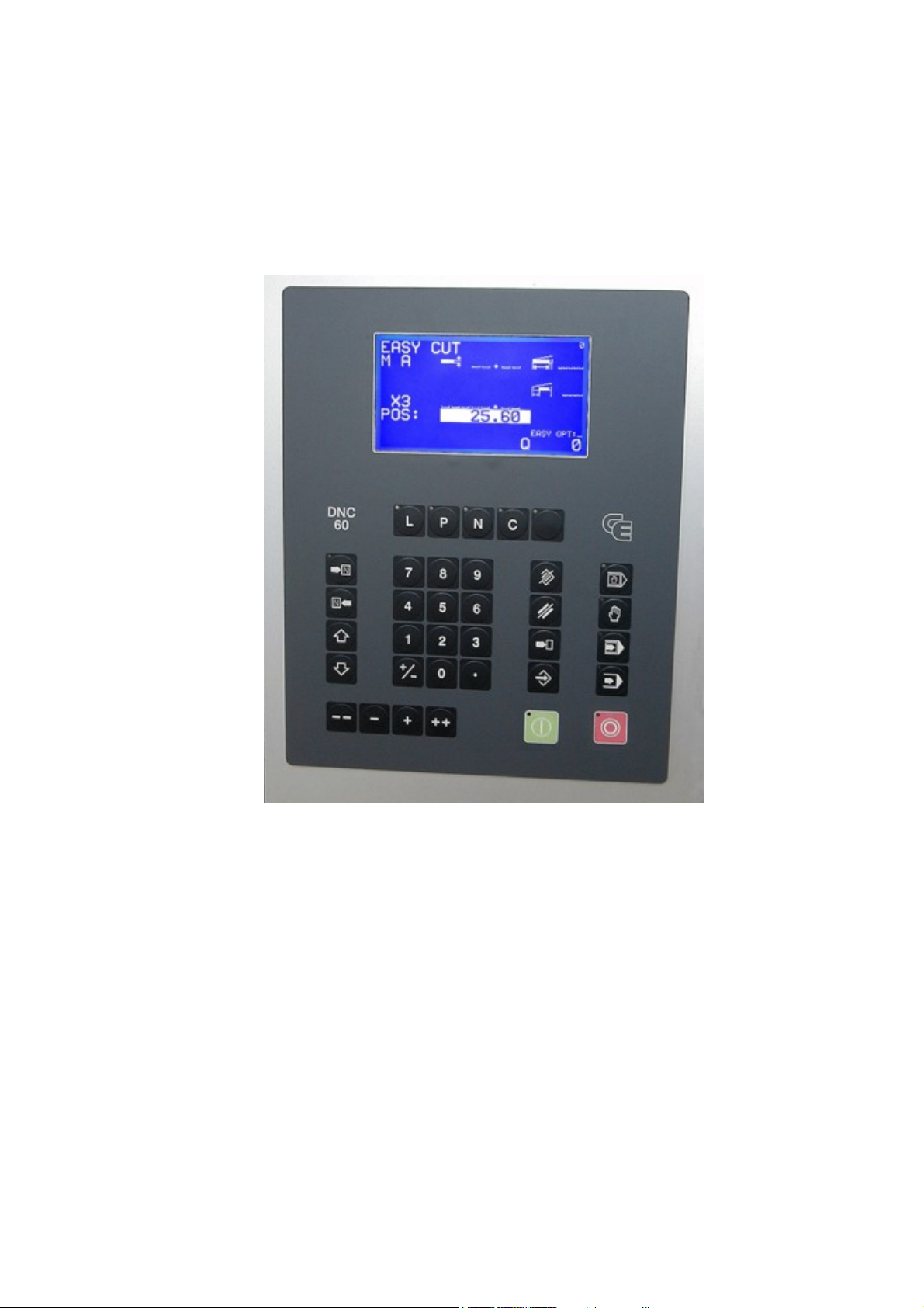
On the machine parameters page N° 01, you will find the following fields:
Softs:
PIC
Key:
Language
CONFIGURATION 8
I/O
GIXME: Version of the Master software contained
in the DNC.
ZIAMBA3: Version of the Master boot software
N2XMng: Version of the axes software
ZZAMBA3: Version of the axes boot software
N2XSA1: Version of the N2XSUP axes software.
Name of the pic software the DNC is equipped
with.
Enables to choose between a cabled key or a
password.
Field allowing a pre-selection of the various
resident languages (by means of the manual
displacement keys (
Field allowing to select the hardware
configuration.
).
PAGE 6 MACHINE PARAMETERS DNC 60 G
Page 9

MACHINE PARAMETERS -01- IGNORE
Softs: GIXMEG/ZIAMBA3 PIC:AA6
N2XMng/ZZAMBA3 N2XSA1 Key:0
Language: [GB] FR GB DE IT ES PT SE NL
CONFIGURATION 8 I/O: 1
X FRONT GAUGE: _ X3: X
00 Axis type __
01 Operating mode __
02 Encoder reso. (I/mm) ___.___
03 Tolerance 0.05
04 Advanced stop _.__
05 Overrun distance ___.__
06 Slow speed distance __.__
07 SP / SN time _.___
08 Acceleration time 0.300
09 Deceleration time 0.400
MACHINE PARAMETERS -02- IGNORE
X3: X
10 Positioning speed 30.00
11 Fin.approach speed __.__
12 Indexing speed ____.__
13 Manual slow speed ___.__
14 Manual high speed ____.__
15 A priori voltage __.___
16 Maximum voltage _.___
17 Minimum voltage _.___
18 Offset voltage __.___
19 Closed loop toler. 80%
20 Max. follow.error __.__
21 Surveillance time _.___
22 Proportional gain _____
23 Integral gain _____
With regard to the axis parameters (P00 –> P28), these are described in the
"N2X BOARD PARAMETERS" manual.
The name of the axes and auxiliary functions can be personalized. An axis or
auxiliary function's name may contain up to 4 characters.
MACHINE PARAMETERS PAGE 7
Page 10

SPECIFICATION OF ALPHANUMERIC CHARACTERS
1) With the aid of the manual displacement keys, run through the
character table until the required character appears in the display.
Note: The
characters.
The
character.
2) Press the
memorized.
3) Repeat operations 1 and 2 for the following characters.
or keys move forward or backward by 4
or keys move forward or backward by 1
or TEACH key (memorize). The first character is
PAGE 8 MACHINE PARAMETERS DNC 60 G
Page 11
MACHINE PARAMETERS DEFINITION
MACHINE PARAMETERS -03- IGNORE
X3: X
24 Differential gain _____
25 Index mode __
26 Index position ______.__
27 Min. limit - 0.00
28 Max. limit + 1000.00
29 Display resolut. _.__
30 Saf. Limit dist. _____.__
31 Supplement stops _
32 Dist.between legs _____.__
33 Sheet pres. speed ___.__
34 Type of axe funct.
35 Retraction distance 2.00
36 Hold-downs/retr.time 1.20
37 Blade gap corr.factor 0.90
P29 DISPLAY RESOLUTION
(Does not function in Inch mode, P68).
1.00
0.10
0.01
axis display to 1 mm accuracy
axis display to 1/10 mm accuracy
(or undefined) axis display to 1/100 mm accuracy
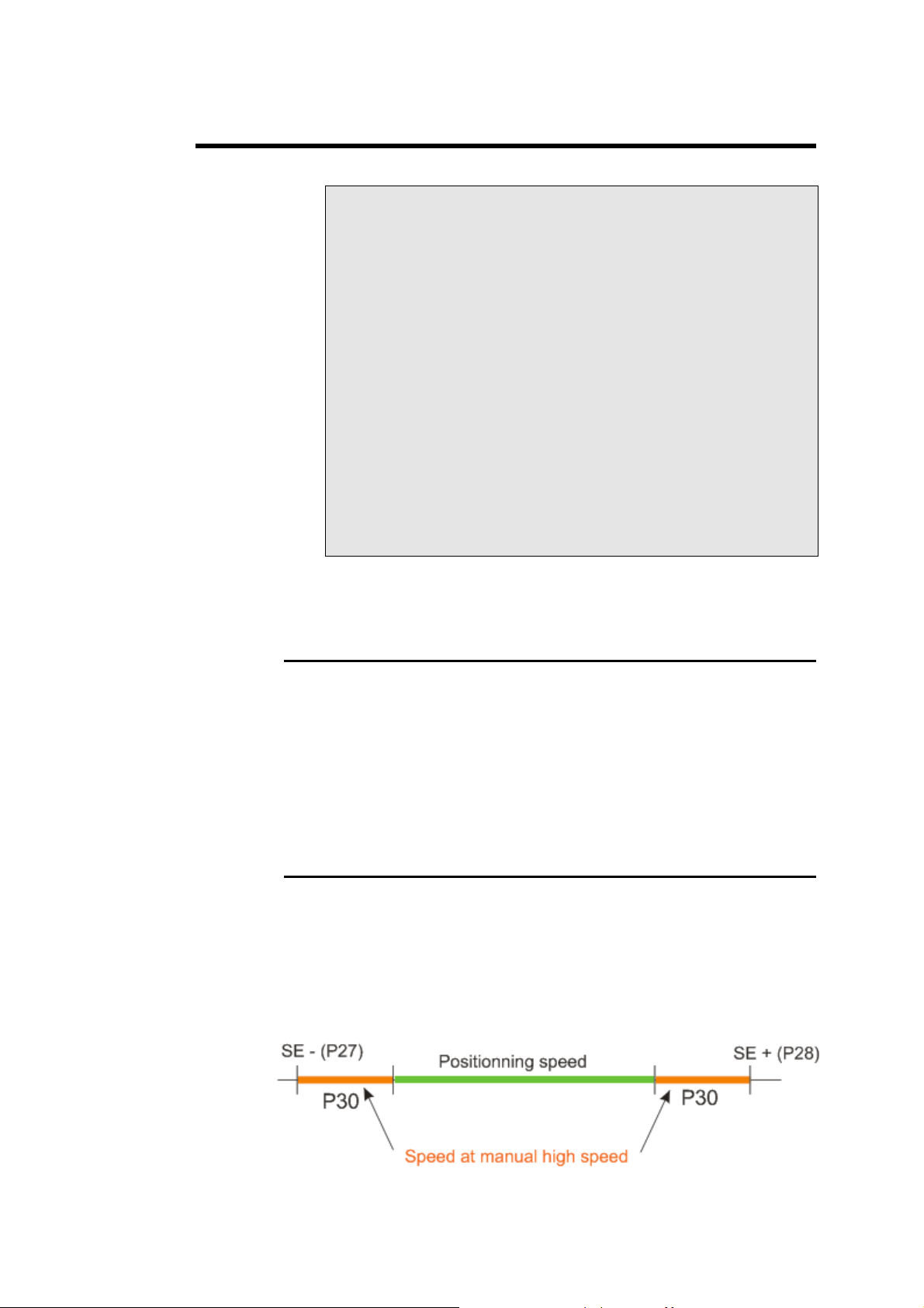
P30 SECURITY DISTANCE (DISTANCE AT LOW SPEED)
This is the safety distance from the stroke end (SE) at which the back gauge
switches from manual high speed (P14) to manual low speed (P13), or vice
versa.
This security distance provides extra security when approaching stroke end
and avoids vibrations at the end of the ball screw drives.
IMORTANT: P30 must be
< [(SE–) – (SE +)] / 2
MACHINE PARAMETERS PAGE 9
Page 12

P31 NUMBER OF SUPPLEMENTARY LEGS
In the case of an axis with several gauge arms, P31 defines the number of
supplementary arms (max. 7).
PAGE 10 MACHINE PARAMETERS DNC 60 G
Page 13

P32 LEG DISTANCE
P32 defines the separation between two consecutive arms. The separation
between 2 consecutive arms being always the same.
P33 SHEET PRESENT SPEED
In the case of a take sheet cycle, without square, the P33 defines the speed at
which the axis moves once the clamp has detected the sheet.
P34 TYPE MANAGEMENT AXIS
Remark: This field is accessible only on X4, X5, X6.
Definitions:
y The dependant axes will follow the cycle sequences.
y The independent axes will execute their own advance sequence with
their signal "Start Xn".
y The axes with automatic "Start" will have their positioning departure
synchronized with the departure of the shear axes (X1/X2/X3).
y The axes with an external "Start" will have their positioning departure
commanded by their signal "Start Xn".
Modes:
0 or __: Auxiliary axis dependant on the cycle with automatic "Start".
1 (D0): Auxiliary axis independent of the cycle with external "Start"
(masked time).
4 (D2): Auxiliary axis dependant on the cycle with external "Start". In this
mode, the axis' sequences follow the cycle sequences but the cycle
does not wait for the end of axis positioning to execute the advanced
sequence (masked time).
2 (D1): Only for X4, this mode indicates that X4 is used as a second
backgauge.
MACHINE PARAMETERS PAGE 11
Page 14

X1, X2: frontgauges
X3, X4: backgauges
Remark: P35, P36, P37 are accessible only on X1 and X3.
P35 RETRACTION DISTANCE
Sufficient distance for the axis retraction.
This retraction is made:
1) Before the cut for backgauges.
By cutting, the sheet spreads. The gauge must be retracted.
2) After the cut for frontgauges.
After the cut, the sheet holder moves upward. The sheet has to be
retracted in order to enable the raising of the blade without rubbing.
The cycle will only wait for the axis to reach its retraction value (in high
speed), then the axis will be stopped independently of the machine cycle.
P36 HOLD-DOWNS TIME
Negative value: This value is interpreted as a retraction delay time and
allows to wait for the hold-down to pressure up before
starting the retraction.
After receiving the HOLD-DOWN CLOSED signal
(0V) the DNC waits for the time programmed in this
parameter before starting the retraction.
Positive value:
The programmable range for this time is situated between -9,99 and +9,99
seconds.
This parameter (programmed positive) defines machine
functioning without the HOLD-DOWN input signal.
Effectively this signal is replaced by the programmed
time. As soon as the CUTTING AUTHORIZATION
signal is furnished, the DNC will wait for the
programmed time then start the retraction.
After this time has elapsed, the DNC considers that the
sheet is held down.
PAGE 12 MACHINE PARAMETERS DNC 60 G
Page 15

P37 CORRECTION FACTOR BLADE GAP
This parameter allows to correct the axis positioning value as a function of
the blade gap defined in the product.
The DNC applies a constant correction, to all the programmed positioning
values, as a function of the blade gap and this parameter.
Cv = Cp + P37 * Jc
Cv Axis positioning value (target value)
CP Programmed value
Jc Blade gap
P37 positive Back gauge cycle
P37 negative Front gauge cycle
At each STOP the DNC displays the real axis value (with the correction).
MACHINE PARAMETERS -04- IGNORE
38 Treatment jitter error _
39 TDC time 0.80s
Clamp: Opened Closed
40 Synchro limit ____.__ ____.__
41 Mech. sheet <-> clamp bottom ___.__
42 Elect. sheet <-> clamp bottom ___.__
43 Clamp disengagement time _.__s
44 Distance Index <-> Blade ___.__
49 Ejection time __.__s
50 Maximal sheet width 4000
51 Distance stop X1 <-> Square ___.__
52 Length of articulated arm ___.__
53 Max angle of articulated arm __._°
P38 TREATMENT JITTER ERROR
Management of encoder impulse errors.
0
2
Other values
MACHINE PARAMETERS PAGE 13
No error handling
Display of alarm messages in the interactive field, but
no machine stop.
Display of alarm messages in the interactive field, the
DNC goes into MANUAL mode, and the pressing of
the
key of the front panel is being simulated.
Page 16

P39 TDC TIME
This parameter is only used if for the RAKE ANGLE (AF2) and CUTTING
LENGTH (AF3) functions only one potentiometer is used.
This time is used to delay the adjustment of the RAKE ANGLE function
(AF2 P70 = 2 or 50) after reception of the TDC signal in order to wait for
the stabilization of the blade at the TDC.
Effectively, in this configuration it is only possible to adjust the rake angle if
the blade is completely stopped at the TDC.
P40 NONE SYNCHRO LIMIT (OPENED CLAMPS / CLOSED CLAMPS)
This double parameter defines the maximum separation authorized between
X1 and X2 with the clamps opened and closed.
This safety control is switched on as soon as an axis moves. If the limit is
reached, the axis is stopped and an error is signalled.
It also allows to deal with all mechanical backgauge configurations (eg.
gauges joined by a bar).
P41 DISTANCE "SHEET PRESENT" <–> "BOTTOM OF
MECHANICAL CLAMP"
This distance should be greater than the distance between the sheet detector
and the mechanical bottom of the clamp.
It is used in sheet taking cycles without square.
P42 DISTANCE "SHEET PRESENT" <–> "BOTTOM OF
ELECTRONIC CLAMP
This distance should be less than the distance between the sheet detector and
the mechanical bottom of the clamp. It is used in sheet taking cycles with
square or in "Square=2" mode.
It prevents the clamps from touching the sheet before they are closed.
"
PAGE 14 MACHINE PARAMETERS DNC 60 G
Page 17

P43 CLAMP DISENGAGEMENT TIME
Remark: The programming of this parameter determines the use or not of
clamps.
Undefined = machine without clamps
Defined = machine with clamps.
This delay is used to make a safety control on the disengagement of the sheet
from the clamps.
In the case of a cycle "without sheet", "without cutting", the clamps will open
then the axis will move backwards to disengage the clamps.
The DNC will control only after the P43 time that the "sheet present" signal
has disappeared. If the sheet remains blocked in the clamps, the axes are
stopped and an error is signalled.
P44 DISTANCE SHEET INDEX <–> BLADE
This parameter indicates the distance between the sheet detection point and
the cutting line.
This parameter is used in the case where an indirect measure of the sheet is to
be made before it is cut.
This working mode is selected by programming the value 2 (D1) in the Take
sheet field.
P49 EJECTION TIME
This parameter should only be programmed in the case where the clamps are
equipped with ejectors.
In the case where the Ejection field has been defined (on the sequence
page) the ejection cycle is as follows:
P49 positive:
1) Set ejection signal
2) Ejection time (P49)
3) Clamp opening
4) Reset ejection signal
P49 negative:
1) Clamp opening
2) Set ejection signal
3) Ejection time (P49)
4) Reset ejection signal
MACHINE PARAMETERS PAGE 15
Page 18

P50 MAXIMUM SHEET WIDTH
This parameter should only be programmed in the event that the machine is
equipped with function (F3), measuring the length of the cut or function
(F2), measuring the rake angle. It defines the maximum cutting length of the
machine.
The three parameters which follow (P51, P52, P53) should be programmed
only for machines equipped with 2 frontgauge clamps (X1, X2) of which X1
(left leg) is fixed and X2 (right leg) is fitted with an articulated arm.
P51 DISTANCE STOP X1 <–> SQUARE
This parameter defines the distance between the left leg and the right end of
the blade (generally the square).
P52 ARTICULATED ARM LENGTH
This parameter defines the distance between the axis of the articulated arm
and the axis of the cylinder holding the sheet.
P53 MAXIMUM ROTATION ARM ANGLE
This parameter defines the maximum angle of rotation authorized for the
articulated arm.
PARAMETRES MACHINE -05- IGNORE
54 Angle MIN: 0.50° MAX (Nom): 5.00°
55 Dist <- fixed point blade 100.00
56 Cycle options __
57 EASYCUT mode at Power on 0
58 Distance Potentiometer 3800
RAKE ANGLE / BLADE GAP TABLES
/ PRESSURE
Material 1: ALU1 Def Thickn: __.__
Thickness Rake angle Bl.gap Pressure
min 0.20 0.10° 0.20 20
I1 2.00 0.50° 0.40 40
I2 3.00 1.50° 0.60 60
I3 4.00 2.10° 0.80 80
max 6.00 3.00° 1.00 100
The four parameters which follow (P54 –> P57) should be programmed only
for machines equipped with a function (AF2) for measuring the rake angle.
PAGE 16 MACHINE PARAMETERS DNC 60 G
Page 19

P54 RAKE ANGLE MIN AND MAX
Min and max rake angle authorized.
P55 DISTANCE Í FIXED POINT BLADE
Distance between the left extremity of the lower blade and the axis of the
rotation point of the upper blade. This rotation point being fixed (no vertical
variation) regardless of the rake angle. (See figure 4, page 43).
the case where this point does not exist the point with the least variation is
In
chosen.
N.B.: This point can be situated outside the cutting range (to the right).
In this case, P55 can be defined negative.
P56 CYCLE OPTION
This parameter is used to define the cyle options explained hereafter.
D0 = 0 The gauge axis starts its positioning when the blade arrives at
the TDC.
D0 = 1 The gauge axis starts its positioning when the blade arrives at
the TDC if the gauge approachs the blade. Positioning in SN
(negative sense).
The gauge axis starts its positioning when the blade arrives at
the BDC if the gauge moves away from the blade. Positioning
in SP (positive sense).
D1 = 1 The gauge axis starts its positioning when the blade arrives at
the BDC.
D2 = 1 The Retraction field is not displayed in key position 0 or 1.
D3 = 1 Activates the messaging of the cycle follow-up information.
P57 ACCESS TO EASYCUT MODE
This parameter allows you to choose the access to the EasyCut page.
0 Access to the MENU page at the start up of the soft
1 Access only to EASYCUT page.
2 No access to the EASYCUT page
Undef Access to the EASYCUT page at the start up of the soft
MACHINE PARAMETERS PAGE 17
Page 20

P58 DISTANCE POTENTIOMETER
Horizontal distance between the left edge of the lower blade and the
potentiometer position. This parameter must be greater than P55 and less
than or equal to P50 (P55 < P58 ≤ P50). If this parameter is not definied, it
will take the default value of P50.
MATERIAL
The name of the material is programmed in 4 characters in the fields located
on the line headed -MATERIAL-.
The name of the material is defined in alpha numerical using the manual
displacement keys. You will find a description of the use of the manual
displacement keys for defining the alpha numerical characters in the
paragraph concerning the auxiliary functions.
DEFAULT THICKNESS
For each material you can program a default thickness. When clearing the
buffer or selecting another material, if the default thickness is defined, then it
will be transferred in the Thickness field of the product.
MACHINE PARAMETERS -06- IGNORE
-- RS232 CHARACTERISTICS --
60 Transmission speed 38400
61 Transmission data 8
62 Stop bits 1.0
63 Parity (-:off, 0:even, 1:odd) _
65 Protocol 6
66 BCC 9
67 None at product search in cassette _
68 Conversion Inch/mm
69 Stop Q Product reached _
Cut Counter: 127
Counter 11h 42min
P60 TRANSMISSION SPEED
Programmable to 300, 600, 1200, 2400, 4800, 9600, 14400, 19200, 38400,
57600 baud.
PAGE 18 MACHINE PARAMETERS DNC 60 G
Page 21

P61 TRANSMISSION DATA
Number of data bits (usually 8) used for transmission.
P62 STOP BITS
Programmable, depending on the peripheral: 1.0, 1.5, 2.0
P63 PARITY
Parity checking.
P65 PROTOCOL
This parameter allows the selection of one of several transmission protocols.
0 / _
1 Identical to 0 or _, but without echo from PC.
2 Protocol for liaison with PUNCHER,
Cybelec standard for PC link with software via
CYBELEC protocol.
When the DNC is sending, the PC sends back a
control character after receiving each character
from the DNC.
When the DNC is receiving, no control
character is sent back to the PC.
READER.
CTS and DSR signal management for flow
control.
When the DNC is receiving, and if the DNC
wishes to halt transmission temporarily to
process the received data, the CTS line goes
low, indicating that only one more character
can be accommodated (if more arrive, they will
be lost).
With this protocol in force, the READER must
thus send only one more character when the
CTS line goes low.
On the other hand, when the DNC is sending,
and the READER forces the CTS line low, the
DNC stops sending characters immediately
(not even 1 more is sent).
3 Same as for protocol 2, but when the DNC
forces the CTS line low, it does not expect to
receive any more characters (not even 1).
Therefore, the READER must not send even 1
more character, the moment the CTS line goes
low.
MACHINE PARAMETERS PAGE 19
Page 22

P66 BCC
This parameter authorizes or inhibits the checksum test in reception mode.
_
1
with checksum
without checksum
TESTS OF THE SERIAL PORT
The serial port of the DNC 60 is SUB-D 9P, plug J5.
y Introduce and verify that the transmission parameters are programmed
as follows:
PARAMETERS RS232 / DIVERS
. . .
-- COMPUTER LINK – 106 BAUD RATE 4800 STOP 1.0
PARITY ODD(1) EVEN(2) _ BITS 8
PROTOCOLE _ BCC ___
y Set a test loopback connector on the serial line connector RS232 to be
tested.
y Press the
The message RUN must flash.
y To stop the test, press the
If you wish as well to test the cable:
y Connect the transmission cable to the DNC and fit a short circuiting
loopback connector on the other end of the cable to be tested.
key to start the test.
(STOP) key.
Test loopback connector
Pin 2 (RXD) wired to pin 3 (TXD)
Pin 4 (DTR) wired to pin 6 (DSR)
Pin 7 (RTS) wired to pin 8 (CTS)
PAGE 20 MACHINE PARAMETERS DNC 60 G
Page 23
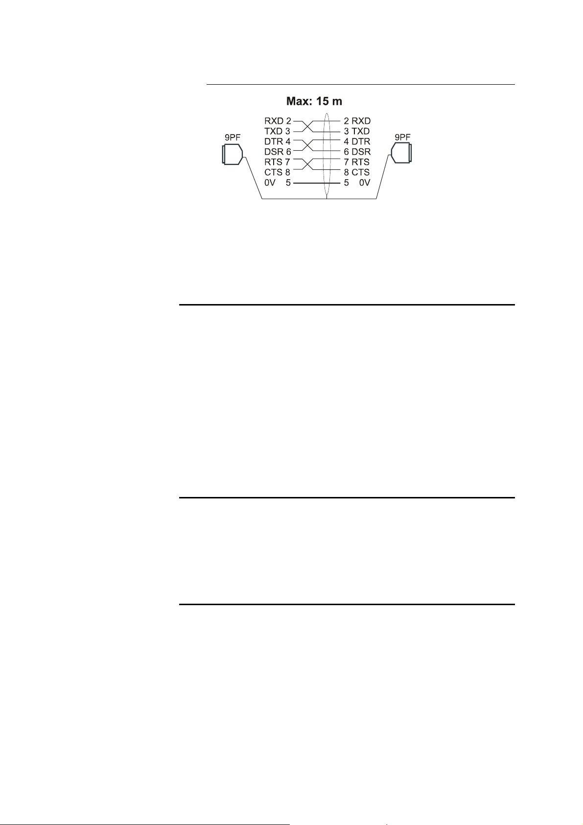
RS 232 transmission cable
Shield: connection on the metallic hood
Blindage: connexion sur le capot métallique
Abschirmung: Anschluss an Metallhülse
P67 NONE AT PRODUCT SEARCH IN CASSETTE
If P67 = 1 The DNC inhibits the various calculations
relative to functions F1, F2, F3 (blade gap, rake
angle, cutting length) whenever a product is
recalled from the product memory. Otherwise,
all the relevant calculations are performed at
each product recall.
If P67 = 2 The DNC inhibits the calculation of the TDC. The
blade upstroke will hence only take account of the
exterior TDC (24V contact of max TDC).
If P67 = 3 The above two conditions are in fare.
P68 CONVERSION INCH/MM
If P68 = 1 Conversion to inches of user data expressed in
mm.
If P68 = 0 or undefined User data expressed in mm.
P69 STOP Q PRODUCT REACHED
This parameter allows to stop the cycle execution in AUTOMATIC mode as
soon as the quantity of products has been reached.
This functionality is active by default (P69 = Undef). To inhibit it, you have
to program P69 = 0.
In page MP 12 (PARAMETRIZING OF THE MACHINE MESSAGES),
write Q PRODUCT REACHED in message 15.
When the quantity of products is reached, the STOP key is activated and the
DNC displays the MACHINE MESSAGES page with Q PRODUCT
REACHED. When releasing the STOP, the quantity of executed products is
reinitialized at 0.
MACHINE PARAMETERS PAGE 21
Page 24
AUXILIARY FUNCTIONS PARAMETERS (AF)
MACHINE PARAMETERS -07- IGNORE
--Auxiliary functions- F1:GAP F2:ANGL F3:BDC
70 Function type 2 2 2
71 Mode: Digital _ _ _
72 Analogue 1 1 0
73 Voltage _ _ _
74 LS distance __ __ __
75 Overrun dist. __ __ __
76 Advanced stop 2 2 2
77 Tolerance 2 2 2
78 Reversal time _.__ _.__ _.__
79 Min.range(D/A) 2 38 2
80 Max.range(D/A) 250 254 254
81 Min.range(prog) 5 34 0
82 Max.range(prog) 165 341 361
On the MACHINE PARAMETERS page N° 7 you will find a set of fields
under the heading:
Fn
Specification of alphanumeric characters
1) With the aid of the manual displacement keys, run through the
character table until the required character appears in the display.
Remark: The
4 characters.
The
1 character.
2) Press the
memorized.
3) Repeat operations 1 and 2 for the following characters.
The auxiliary function pages can only display 3 AF at the same time, whereas
the DNC can handle up to 8.
In order to visualize the other AF, position the cursor on any field pertaining
to parameters 70 to 78, and use the manual displacement keys.
In these fields you can enter the auxiliary
function identifier using 4 alphanumeric
characters (n=1 to 8).
On initialisation, these appear as F1, F2 .... F8.
:
or keys move forward or backward by
or keys move forward or backward by
or TEACH key (memorize). The first character is
PAGE 22 MACHINE PARAMETERS DNC 60 G
Page 25

P70 FUNCTION TYPE
Definitions:
y The dependent auxiliary functions follow the sequences of the cycle.
y The auxiliary functions with automatic START have their
management start synchronised with their axis start.
y The independent auxiliary functions execute their own advance
sequence and START with their signal START AFn.
y The auxiliary functions with external START have their management
start triggered by their START AFn signal.
Programming:
P70 = undefined
P70 = 0
P70 = 1 (D0)
P70 = 2 (D1)
P70 = 4 (D2)
AF dependent on the machine cycle with
automatic START.
The code 0 prohibits display of the function,
but allows to reserve the function outputs in
digital mode. The aim of this is to avoid a
difference of the auxiliary functions as a
function of the configuration of the machine
options. The wiring can be standardized.
Cycle-independent AF with independent
advance sequence and external START.
Special AF with internal calculations:
- for F1 and F5: blade gap
- for F2: cutting angle
- for F3: cutting length (BDC)
- for F4: timer for flying cut
- for F7: sheet thickness measurement
AF dependent on the cycle for the advance
sequence, but having its own management
start, supplied by its corresponding START
AFn signal.
P71 DIGITAL MODE
This parameter configures the AF in digital mode.
The programmed number (maximum 8) corresponds to the number of 24V
output wires (binary coded) for the chosen function. This number of outputs
is reserved.
Calibrating digital functions
The parameters P79 and P80 can be used to define a limit for the binary
codes attributed to the function.
Example: A digital function programmed with 3 wires accepts the digital
values from 0 to 7. These values are used by default if P79 and
P80 are not programmed. If you program P79 = 2 and P80 = 5,
the codes 0, 1, 6 and 7 are excluded.
MACHINE PARAMETERS PAGE 23
Page 26
P72 ANALOGUE MODE
This parameter configures the AF in analogue mode, so that it can be used as
an axis with analogue position measurement, or measurement of any other
physical attribute (temperature, pressure, etc.).
Mode 1: Reservation of 2 digital outputs (SP/SN) and a digital input
(potentiometer).
Mode 0: Reservation of just one analogue input (F3 in cutting length
mode).
Calibration of an analogue function
1) Move down the function until its minimum position is reached, by
placing the cursor on P79 and pressing the
2) Perform the TEACH of the minimum D/A value (P79 of the function),
by pressing the
will appear in the active field (value range between 1 and 254).
3) Program in P81 the physical value corresponding to this state (mm,
degrees, pressure, temperature, etc.).
4) Move up the function until its maximum position by placing the cursor
on P80 and pressing the
5) Perform the TEACH of the maximum D/A value (P80 of the function),
by pressing the
6) Program in P82 the physical value corresponding to this state (mm,
degrees, pressure, temperature, etc.).
key. The D/A value read on the potentiometer
key.
key (value less than 255).
key.
P73 VOLTAGE MODE
This parameter configures the AF in voltage mode. In this mode the DNC
supplies a voltage of between 0V and 10V.
Reserves an analogue output.
Calibration of a tension function
1) Program in parameter 79 the minimum D/A value, while aware that:
0 V corresponds to 0 D/A
+10 V corresponds to 254 D/A.
2) Program in P81 the physical value corresponding to this state (mm,
degrees, pressure, temperature, etc.).
3) Program in parameter P80 the maximal D/A value, while aware that:
0 V corresponds to 0 D/A
+10 V corresponds to 254 D/A.
4) Program in P82 the physical value corresponding to this state (mm,
degrees, pressure, temperature, etc.).
PAGE 24 MACHINE PARAMETERS DNC 60 G
Page 27

NB: The 1 to 3 steps can be realized by teaching, using the manual keys.
The manual keys will increase or decrease the P79 or P80 values
(according to the cursor position) meanwhile the voltage corresponding
to the reached digital value will be output on the analogue auxiliary
function.
The
1 to 10 units.
The
1 to 10 units.
For the 5 following parameters (P74 → P78), you will find a diagram explaining the positioning of an AC axis at 1 or 2 speeds in the notice "N2X BOARD
PARAMETERS" at figure 1. The only difference to take into account is that
the units of measurement are replaced by increments from the D/A unit.
or keys will increase respectively the D/A value of
or keys will respectively decrease the D/A value of
P74 LS DISTANCE
Switch on low speed signals "n" D/A units before the required position is
reached.
Default value = no low speed.
Type value = 10.
This distance must be sufficiently large to enable the axis to stabilise at the
required low speed.
Programming this parameter reserves an extra (HS) digital output.
P75 OVERRUN DISTANCE
Defines, in D/A units, the distance allowing for an overrun to catch up with
any play in the auxiliary axis.(unidirectional positioning).
Value type = 0 (without overrun).
The sign preceding the value determines the direction at the end of
positioning, namely:
Sign negative: the axis terminates positioning in SN.
Sign positive: the axis terminates positioning in SP.
P76 ADVANCED STOP
Distance in D/A units before the aimed-for position at which the movement
command is cut.
Value type = 1 (depending on axis inertia).
The inertia of the axis determines this distance.
MACHINE PARAMETERS PAGE 25
Page 28

P77 TOLERANCE
Maximum tolerance, in D/A units, authorized each side of the position value
without having to reposition with a new start.
Value type = 2.
Insensitive zone.
P78 REVERSAL TIME
This parameter corresponds to the waiting time before a change in the
positioning direction (directional change timeout).
P79 MINIMUM RANGE (D/A)
Digital value from the analogue-to-digital convertor for the minimum
position of the function.
This parameter functions as an electronic limit switch for the analogue AF.
To determine the required value, the cursor should be positioned on the
parameter and the axis moved to the desired limit switch position. Then,
)
press the TEACH key
potentiometer position will appear in this field, and effectively becomes the
minimum limit switch value not to be exceeded.
Attention: The value must be greater than zero, otherwise this indicates that
the axis has reached the electrical limit of the potentiometer.
(
. The D/A value corresponding to the
P80 MAXIMUM RANGE (D/A)
Digital value from the analogue-to-digital convertor for the maximum
position of the function.
This parameter functions as an electronic limit switch for the analogue AF.
To determine the required value, the cursor should be positioned on the
parameter and the axis moved to the desired limit switch position. Then,
)
press the TEACH key
potentiometer position will appear in this field, and effectively becomes the
maximum limit switch value not to be exceeded.
Attention : The value must be less than 255, otherwise this indicates that the
axis has reached the electrical limit of the potentiometer.
These 2 parameters (P79, P80) are generally determined by use of the
TEACH key for analogue functions.
(
. The D/A value corresponding to the
PAGE 26 MACHINE PARAMETERS DNC 60 G
Page 29

P81 MINIMUM RANGE (PROGR)
Programming value which corresponds to the minimum D/A (P79).
P82 MAXIMUM RANGE (PROGR)
Programming value which corresponds to the maximum D/A (P80).
This parameter determines the unit with which you want to work.
CUTTING PRESSURE PARAMETERS (AF6)
MACHINE PARAMETERS -13- IGNORE
-- PRESSURE PARAMETRIZING (AF6) --
83 MINIMAL BLADE UP PRESSURE: 10
84 RAKE ANGLE ADJUST. PRESSURE: 20
85 b ELECTRICAL BLADE GAP: _
a BLADE GAP ADJUST. PRESSURE: 20
86 BLADE UP PRESSURE: 80
87 BLADE UP GAIN: 200
88 ACC.TIME BLADE DOWN PRESSURE: 1.00
89 a DEC.TIME BLADE DOWN PRESSURE: 1.00
b DEC.TIME MANUAL PRESSURE: _.__
90 ACC.TIME BLADE UP PRESSURE: 1.00
91 DEC.TIME BLADE UP PRESSURE: 1.00
92 DECOMPRESSION TIME: 1.00
P83 MINIMAL BLADE UP PRESSURE
This parameter indicates the remaining minimum pressure at the raising of
the blade when it has reached the max. TDC.
P84 RAKE ANGLE ADJUST. PRESSURE
This parameter indicates the pressure used to carry out the angle adjustment.
Remark: If AF2 and AF3 are calibrated, the used pressure is the max.
pressure of parameters P84 and P85.
MACHINE PARAMETERS PAGE 27
Page 30

P85A ELECTRICAL BLADE GAP
This parameter indicates that the blade gape is adjusted with a electrical
motor and not with hydraulic pressure. (Value = _, 0 ou 1)
P85B BLADE GAP ADJUST. PRESSURE
This parameter indicates the pressure used to carry out the blade gap
adjustment
Remark: If AF2 and AF3 are calibrated, the used pressure is the max.
pressure of parameters P84 and P85.
P86 BLADE UP PRESSURE
This parameter indicates the pressure level used to carry out the raising of the
blade.
P87 BLADE UP GAIN
This parameter is used to soften the arrival at the TDC on the blade raising.
y Default value (if Undef) = 100.
y A too low value can limit too much the upstroke pressure of the blade
(the raising doesn't cushion).
y More the value is strong, more the softening comes late. On the other
hand it is more sloping.
P88 ACC. TIME BLADE DOWN PRESSURE
This parameter indicates the required time to reach the downstroke pressure
of the blade.
This parameter corresponds to a pressure acceleration ramp.
P89A DEC. TIME BLADE DOWN PRESSURE
This parameter indicates the required time to reach the zero pressure at the
end of the descent of the blade.
This parameter corresponds to a pressure deceleration ramp.
PAGE 28 MACHINE PARAMETERS DNC 60 G
Page 31

P89B DEC. TIME MANUAL PRESSURE
This parameter indicates the required time to reach the zero pressure at the
end of the manual movement of the blade.
This parameter corresponds to a pressure deceleration ramp. The default
value is 0,3 seconds (max. 0,3 seconds).
P90 ACC. TIME BLADE UP PRESSURE
This parameter indicates the required time to reach the upstroke pressure of
the blade.
This parameter corresponds to a pressure acceleration ramp.
P91 DEC. TIME BLADE UP PRESSURE
This parameter indicates the required time to reach the minimum upstroke
pressure (P83) at the end of the ascent of the blade.
This parameter corresponds to a pressure deceleration ramp.
P92 DECOMPRESSION TIME
This parameter indicates the waiting time after the cut before the blade
moves up again.
CALIBRATION CUTTING PRESSURE PARAMETERS (AF6)
MACHINE PARAMETERS -14- IGNORE
93 TDC MAX SENSOR DISTANCE IN MM: 20
IN U D/A: 14
-- PRESSURE CALIBRATION (AF6) --
AF6 AF6
U Pr U D/A
Min = P81 1 = P79 2
25% 64
50% 128
75% 192
Max = P82 100 = P80 254
MACHINE PARAMETERS PAGE 29
Page 32

P93 TDC MAX SENSOR DISTANCE
This parameter can be considered as an advanced stop which allows to avoid
a shock at the top of the machine when the blade is moving up.
ATTENTION: This parameter must be programmed in millimeter after the
calibration of AF2 and AF3, for after that it is converted and displayed (just
underneath) in U D/A as soon as you leave the field. This U D/A value is
then exploited by the software for the management of the angle adjustment
tolerance.
This parameter enables to improve the management of the angle adjustment
tolerance.
EXTENDED BLADE GAP PARAMETERS (8 SEGMENTS)
MACHINE PARAMETERS -15- IGNORE
-- BLADE GAP WITH 9 POINTS (8 SEGMENTS) --
AF1 AF1 (TEACH) AF5
U Pr U D/A U D/A
Min = P81 1 = P79 2 2
Int1 12 32 16
Int2 25 64 32
Int3 37 96 48
Int4 50 128 64
Int5 62 160 80
Int6 75 192 96
Int7 87 224 112
Max = P82 100 = P80 254 128
PAGE 30 MACHINE PARAMETERS DNC 60 G
Page 33

X BACKGAUGE FOLDAWAY PARAMETERS
MACHINE PARAMETERS -16- IGNORE
-- X BACKGAUGE FOLDAWAY --
P94 PARK DISTANCE: _____.__
PARK TARGET: +_____.__
P95 CRAWL DISTANCE: _____.__
CRAWL TARGET: +_____.__
P96 HYDRAULIC FOLDAWAY TIME:
a: IN: _.__ b: OUT: _.__
c: DELAY: _.__ d: PRESSURE: _.__
P97 LS/HS X3 COMMUTATION: _
P98 DELAY RESET OUT HOLD-DOWNS: _.__
P99 PULSATE TDC DURATION: _.__
P100 EASY OPTIMIZER _
P101 AFS ADJUSTMENT: 1 x / ___
P104 CUT ON MIDDLE _
P94 PARK DISTANCE
This parameter is used for the backgauge foldaway. It defines the safety
distance from the max. limit switch where the gauge is retracted.
The PARK TARGET (= LSW max – P94) is the absolute value from which
the gauge is completely retracted.
For more details, see User Guide, Ch. Functionalities, Backgauge foldaway.
P95 CRAWL DISTANCE
This parameter is used for the backgauge foldaway. It defines the transition
distance between the normal position of the backgauge and its retracted
position.
The CRAWL TARGET (= PARK TARGET – P95) is the absolute maximum
value of the backgauge for a normal use.
For more details, see User Guide, Functionalities, Backgauge foldaway.
MACHINE PARAMETERS PAGE 31
Page 34

P96 HYDRAULIC FOLDAWAY TIME
This parameter is used for the backgauge foldaway activated by a hydraulic
cylinder. It defines the dwell time of the hydraulic system of the gauge
foldaway.
L In order to activate this functionality, you have to program:
• P94 (PARK DISTANCE)
• P95 (CRAWL DISTANCE) =
a: In
Temporization while the pressure is active for the foldaway. (Max.
9.99seconds)
b: Out
Temporization while the backgauge goes at his normal height of use. (Max.
9.99seconds)
c: Delay
This parameter extends the time for the signal of the pressure up and down
command for the foldaway. (Max. 2.54seconds)
0
d: Pressure
Pressureof for the hydraulic foldaway rise. The value in this field is percent.
The minimum value (0%) corresponds to P81 Min. Range (prog) of the
AF6 and the maximum value (100%) at P82 Max. Range (prog) of the
AF6.
If the cursor is on this field, it’s possible move up or down the hydraulic
foldaway with the key
or .
PAGE 32 MACHINE PARAMETERS DNC 60 G
Page 35

P97 LS/HS X COMMUTATION
If this parameter P97 is configurated with value 1, then:
y at each entry of X in the retraction zone (= P94 + P95), the DNC
passes to LS on X.
y at each exit of X from the retraction zone (= P94 + P95), the DNC
passes to HS on X.
CAUTION: To use this functionality, it is recommended to not configure
the LSX input.
P98 DELAY RESET OUT HOLD-DOWNS
The independent management of the hold-downs can be done uniquely with
a two-level pedal. The 1
the downstroke of the blade.
Right from the beginning of the blade upstroke, the value of parameter P98
defines the delay (from 0 to 9,99 seconds) before disactivating the Hold-
downs output.
P98 = Undef is considered as a delay zero (0 sec).
st
level activates the hold-downs and the 2nd activates
P99 PULSATE TDC DURATION
When the Pulsate TDC output is configured, parameter P99 defines the
activation time (from 0 to 9,99 seconds) of this output, as soon as the blade
arrives at the TDC calculated by the DNC.
For P99 = Undef or P99 = 0, the Pulsate TDC output is not activated.
P100 EASY OPTIMIZER
This parameter is used for the Easy Optimizer mode.
If P100 = 1, the MODE EASY OPTIMIZER field appears in the
EASYCUT page.
To activate this functionality, the value 1 must furthermore be programmed
in the MODE EASY OPTIMIZER field of the EASYCUT page.
For more details, see: User Guide, The EASYCUT page, EasyCut page in
Easy Optimizer mode.
MACHINE PARAMETERS PAGE 33
Page 36

P101 AFS ADJUSTMENT ONCE OUT OF …
This parameter allows to increase the cutting cadence by not raising each
time up to the top of the machine (TDC max).
In AUTOMATIC or SEMI-AUTOMATIC mode:
y If P101 = 0, the blade never raises up to the top of the machine
(TDC max) during the whole cycle. The blade gap and the angle
adjustment is executed only once at the start-up of the cycle.
y If P101 = 1 or P101 = Undef, the blade raises each time up to the
top of the machine (TDC max) in order to execute the blade gap and
the angle adjustment.
y If P101 = n (2 ≤ n ≤ 999), the blade raises up to the top of the
machine each n
adjust-ment. For the other n-1 times, the blade raises up to the TDC
pot only.
th
time in order to execute the blade gap and the angle
P104 CUT ON MIDDLE
This parameter allows to active the function of offset of sheet origin
. This function allows the sheet cutting anywhere on the width of
the machine.
THICKNESS MEASUREMENT PARAMETERS (8 SEGMENTS)
MACHINE PARAMETERS -17- IGNORE
-THICKNESS MEASUREMENT 9 POINTS (8 SEGM.)-
AF7 AF7 (TEACH)
U Pr U D/A
Min = P81 0 = P79 2
Int1 10 32
Int2 15 64
Int3 20 96
Int4 40 128
Int5 60 160
Int6 80 192
Int7 100 224
Max = P82 120 = P80 254
PAGE 34 MACHINE PARAMETERS DNC 60 G
Page 37

SHEET SUPPORT
For more details on how to use the sheet support feature, please refer to
section Sheet Support, on page 55 of t
MACHINE PARAMETERS -18- STOPPED 3
P103 PIN SECURITY ZONE _.__
-- SHEET SUPPORT FUNCTION --
P115 SHEET SUPPORT START DELAY: _.__
P105 SHEET SUPPORT TIME UP: _.__
P102 SHEET SUPPORT TIM
P106 SHEET SUPPORT TIME DOWN: _.__
b : SECURITY DELAY DOWN: _.__
P107 RETURN SHEET SUPPORT AT TDC: _
-- A-TW FUNCTION --
P116 A-TW START DELAY: _.__
P108 A-TW TIME UP: _.__
P109 A-TW TIME: _.__
P110 A-TW TIME DOWN: _.__
P111 RETURN A-TW AT TDC: _
his manual.
P102 Sheet Support Time
This specified time starts when the blade is at BDC and the sheet support at a
low position, and ends when the support starts going up.
(Value range: from 0 to 9.99 seconds)
P105 Sheet Support Time Up
Estimation of the time needed for the sheet support to go up to the high
position.
(value range : from 0 to 9.99 seconds)
P106 Sheet Support Time Down
This parameter is an estimation of the time needed for the sheet support to go
down to the lower position.
(value range : from 0 to 9.99 seconds)
P106b Security Delay Down
This parameter is the specified time at the end of which the numerical control
checks whether the sensor on position 1 is activated or not.
MACHINE PARAMETERS PAGE 35
Page 38

(Value range: from 0.01 to 2.54 seconds, if no value is specified, no check is
performed)
P106b<P106
P107 Return Sheet Support at TDC
This parameter controls whether the sheet support goes back to position 1
(high) after the blade reaches TDC or whether it remains in the lower
position.
If the value for this parameter is 1, the sheet support goes to position 1 at the
end of the time specified in P102.
You may also use parameter P107 if you need to ensure that the sheet
support only goes up after blade, eg, to avoid collisions between the two.
P115 Sheet Support Start Delay
This parameter is the delay between the cutting authorization signal and the
start of the sheet support cycle.
(Value range : from 0.01 to 9.99 seconds, Default value = 1 second)
Reminder: in a work cycle without sheet support, parameter P36 is the
specified time between the cutting authorization and the moment where the
hold-downs are tightened, that is, when the blade can start going down.
When using a sheet support, you must enter a value for P36: this parameter
then acts as an additional security.
As a rule, the sheet support cycle must start after the metal is clamped: P115
must be greater than P36.
However, in special situations, the support cycle may need to start before the
metal is clamped. In this case, P115 must be less than P36.
Using a pressure sensor may shorten the duration of both P115 and P36.
ANTI-TWIST PARAMETERS
For more details on how to use the anti-twist feature, please refer to section
Sheet Support on page 63 of this manual.
P116 A-TW Start Delay
This parameter is the delay between the cutting authorization signal and the
start of the anti-twist device's cycle.
(Value range : from 0.01 to 9.99 seconds, Default value = 1 second)
Reminder: in a work cycle without sheet support, parameter P36 (Hold
Downs Time) is the specified time between the cutting authorization and the
moment where the hold-downs are tightened, that is, when the blade can start
going down.
PAGE 36 MACHINE PARAMETERS DNC 60 G
Page 39

When using a sheet support, you must enter a value for P36: this parameter
then acts as an additional security.
As a rule, the anti-twist device cycle must start after the metal is clamped:
P116 must be greater than P36.
However, in special situations, the anti-twist device cycle may need to start
before the metal is clamped. In this case, P116 must be less than P36.
Using a pressure sensor on the hold-downs may shorten the duration of both
P116 and P36.
P108 A-TW Time Up
Estimation of the time needed for the anti-twist device to go up to the high
position.
This parameter is similar to P105 for sheet support.
P109 A-TW Time
This specified time starts when the blade is at BDC and the anti-twist device
at a low position, and ends when the A-TW device starts going up.
(Value range: from 0 to 9.99 seconds)
P110 A-TW Time Down
This parameter is an estimation of the time needed for the sheet support to go
down to the lower position.
(value range : from 0 to 9.99 seconds)
P111 Return A-TW at TDC
If the value for this parameter is 1, the anti-twist device goes back up after
the blade reaches TDC and the time specified in P109 has elapsed.
Use this parameter if you need the anti-twist device to go back up after the
blade.
MACHINE PARAMETERS PAGE 37
Page 40

MACHINE PARAMETERS -19- 3
P112 SEQUENTIEL SENDING FAs: _
P113 DELAY OPENING HOLD-DOWNS : _.__
P114 DURATION OPENING HOLD-DOWNS : _.__
P117 TOGGLE MODE LEVEL 3/2/3 (1=YES)_
P118 I/O VISUALIZATION IN RUN (1=YES)_
P119 NIBBLING MODE (1=YES) _
P120 UNINTERRUPTIBLE CUT (1=YES) _
P121 SHOW ALL MACH. PAR. (1=YES) _
P122 PRINT ALL MACH. PAR. (1=YES) _
P123 KEY 0 BLOCKS UTILIZATION (1=YES)_
P112 SEQUENTIEL SENDING FAS
If this parameter is at 1, the auxiliary functions (1st blade gap, 2nd blade gap,
cutting angle) are adjusted one after the other.
P113 DELAY OPENING HOLD-DOWNS
In the hold-down hydraulic circuit, an opening valve is integreted. The
POuvSerT output drives this valve.
The activation of the POuvSerT output will be temporized by the parameter
Delay opening hold-downs and a potientiometer after the start of the
blade goes up. A potientiometer must be connected on 4
1 of connector J8).
This function is always active, except if the value of the potentiometer is
smaller than 20 units D/A.
See also parameter P114.
th
analogic input (Pin
P114 DURATION OPENING HOLD-DOWNS
This parameter allows to limit the duration of POuvSerT output activation.
P117 TOGGLE MODE LEVEL 3/2/3
When this parameter is active (set to 1), the operator can switch from 3 to 2
and conversely by holding down the key
PAGE 38 MACHINE PARAMETERS DNC 60 G
for a few seconds.
Page 41

This parameter won't let you toggle from level 0 to level 1. It is only intended
to help you start a machine quickly.
P118 I/O VISUALIZATION IN RUN
When this parameter is active (set to 1), the operator may view the status of
all inputs/ouputs while in cycle, by pressing either
or
P119 NIBBLING MODE
This parameter lets you activate or de-activate the nibbling mode (for more
details, please refer Nibbling Mode section of the DNC60G16 User Guide).
1 = actives
0 or undef = de-activated.
P120 UNINTERRUPTIBLE CUT
When this parameter is active (set to 1), the blade will go down to BDC
without stopping - even if you release the pedal. This applies only from the
moment the hold-down is down (tightened).
P121 SHOW ALL MACH. PAR.
.
When this parameter is active (set to 1), all machine parameters will display,
including unused parameters such as unassigned auxiliary functions.
If this parameter is set to 0 or undefined, parameters that are connected to
another (unset) parameter do not display.
Ex: P39 (TDC TIME) only displays if F2 is in "cutting angle" mode or if
P121 is set to 1.
P122 PRINT ALL MACH. PAR.
When this parameter is set to 1, you can print all machine parameters simply
by pressing
If this parameter is undefined, enter 1, then move the cursor out of the field,
and press
What is referred to as printing is the process of downloading the content of
all all Machine Parameter screens to the HyperTerminal utility (on a PC).
For more information on this operation, please refer to section
HyperTerminal in the DNC60G16 User Guide.
.
to print all machine parameters.
MACHINE PARAMETERS PAGE 39
Page 42

P123 KEY 0 BLOCKS UTILIZATION
This parameter is actually an additional security for the DNC.
When this parameter is set to 1 with the DNC is in key level 0 mode, the only
actions possible are to press or release the pedal or the Stop button.
To unblock the DNC, simply switch key levels.
PAGE 40 MACHINE PARAMETERS DNC 60 G
Page 43

SPECIAL SHEAR FUNCTIONS
AUXILIARY FUNCTIONS Type of management (P70)
F1/F5: Blade gap 2
F2: Cutting angle 2
F3: Cutting length 2
F4: Flying cut 2
F6: Pressure 2
F7: Sheet thickness measurement 2
BLADE GAP FUNCTION (F1)
FIELDS TO
PROGRAM
Material tables 0.01Î9.99
P70 F1 2
P72 F1 (par ex.) 1
P79 F1 1Î254
P80 F1 1Î254
P81 F1 0Î999
P82 F1 0Î999
On the sequence
page:
-
- select the
MATERIAL
with the manual
displacement
keys.
The BLADE GAP function can be adjusted using two motors placed at each
end of the machine. This configuration allows to simplify the adjustment
mechanism of the blade gap.
nd
AF used for this adjustment is AF5; it is programmed and calibrated
The 2
the same as AF1 (in BLADE GAP mode).In this mode, the AF5 does not
appear on the screen but is programmed automatically when a calculation is
made or a blade gap function is programmed. It is also moved simultaneously
with the AF1 in AUTOMATIC or MANUAL.
VALUES COMMENTS
Calculation constants for
blade gap according to
material and thickness.
Management type
Analogue mode
Value D/A min. (teach)
Value D/A max. (teach)
Min programming range
Max programming range
0.01Î99.99
ALU
(for ex.)
Sheet metal thickness
Sheet metal type
Note : F1 / F5 could be defined as analogue, voltage, or digital, by
defining parameters 71, 72 or 73 (see relevant text, page 23/24).
SPECIAL SHEAR FUNCTIONS PAGE 41
Page 44

CALIBRATION OF FUNCTIONS F1 / F5
1) Adjust the blade gap function to its minimum position, by placing the
cursor in the F1 column of row P79, and pressing the
2) Perform the TEACH for the minimum D/A value (row P79, column
F1) with
written in to the active field (value in range 1-254).
3) Program in P81 the measured distance (in 1/100 mm) between the
blades.
4) Adjust the blade gap function to its maximum position by placing the
cursor in the F1 column of row P80, and pressing the
5) Perform the TEACH for the maximum D/A value (row P80,
column F1) with
6) Program in P82 the measured distance (in 1/100 mm) between the
blades.
If F6 is defined in pressure mode (see function F6 Pressure), each pressing
on a manual key provokes the pressure rise to P85 (Blade gap adjustment
pressure). When releasing the key, the pressure will fall back to 0.
key. The D/A value read on the potentiometer will be
key (value less than 255).
key.
key.
BLADE GAP CALCULATION
The calculation of the blade gap is performed each time the sheet metal
thickness or sheet metal type fields are programmed (according to the table
of materials explained earlier).
The value of blade gap calculated on the sequence page corresponds to an
accuracy of 1/100 mm.
Manual programming of the blade gap (in 1/100 mm) on the (
page remains possible.
) function
PAGE 42 MACHINE PARAMETERS DNC 60 G
Page 45

g
RAKE ANGLE (F2) AND CUTTING LENGTH (F3)
FUNCTIONS
(WITH ONLY ONE POTENTIOMETER)
FIELDS TO
PROGRAM
P70 F2 2
P72 F2 1
P79 F2 1Î254
P80 F2 1Î254
P81 F2 (b-a) mm
P82 F2 (c-a) mm
P70 F3 2
P72 F3 0
P79 F3 1Î254
P80 F3 1Î254
P81 F3 0 mm
P82 F3 (c) mm
P50 1Î99999
Table of materials 0.01Î9.99
P55 0.01Î999.99
On sequence page :
-
- choose the
MATERIAL using
the manual
displacement keys.
-
VALUES COMMENTS
Type of management
AF2 analog
Min D/A value (teach)
Max D/A value (teach)
Minimum programming range.
(See figure 4, page 43)
Maximum programming
range. (See figure 4, page 43)
Type of management
AF3 analog
Min. D/A value (teach)
Max D/A value (teach)
Minimum programming range
Maximum programming range
(see figure 4, page 43).
Maximum cutting length
Rake angle according to
material and thickness
Dist. between left edge and
fixed point blade
0.01Î99.99
ALU
1Î99999
(e.g.)
Sheet metal thickness
Sheet metal type
Sequence cutting length
Rake angle and cutting depth
measuring potentiometer
Measurin
point
Fixed
rotation point
max
<min
c
b
Lower blade
P 55
Figure 4
SPECIAL SHEAR FUNCTIONS PAGE 43
Page 46

p
CALIBRATION OF THE AUXILIARY FUNCTION RAKE
ANGLE F2
Rake angle and cutting depth
measuring potentiometer
Fixed
rotation
oint
P54 max.
P54 min.
+
_
Dmax.
P81
P82
Lower blade
P55
P58
P50
1) Program in P50 the maximum cutting width of the machine.
2) Program in P54 the max. angle and the min. angle of the blade.
3) Program in P55 the horizontal distance between the left edge of the
lower blade and the axis of the rotation point of the upper blade.
4) Program in P58 the horizontal distance between the left edge of the
lower blade and the potentiometer position.
5) Move the blade up to the max. TDC (Dmax distance) by setting the
cursor in P80 of F3 and pressing the
6) Move the blade up to its min. angle by setting the cursor in P79 of F2
and pressing the
7) Perform the TEACH of the min. D/A value (P79 of F2). The (in mm)
calculated vertical distance between the fixed rotation point and the
upper blade, at the point where the potentiometer is found, is transferred
in P81 of F2.
8) Move the blade up to its max. angle by setting the cursor in P80 of F2
and pressing the
key (by keeping the Dmax distance).
key.
key.
PAGE 44 MACHINE PARAMETERS DNC 60 G
Page 47

p
9) Perform the TEACH of the max. D/A value (P80 of F2). The (in mm)
calculated vertical distance between the fixed rotation point and the
upper blade, at the point where the potentiometer is found, is transferred
in P82 of F2.
If F6 is defined in pressure mode (see function F6 Pressure), each pressing
on a manual key provokes the pressure rise to P84 (Rake angle adjustment
pressure). When releasing the key, the pressure will fall back to 0.
CALIBRATION OF THE AUXILIARY FUNCTION CUTTING
LENGTH F3
Rake angle and cutting depth
measuring potentiometer
+
_
Fixed
rotation
oint
P54 max.
P82
P81 = 0
Lower blade
P55
P58
Remark: The upstroke / downstroke of the blade can also be carried out by
P50
the pedal. In this case, if the elapsed time between two pedal
pressings is less than 2 seconds, the blade will move in the same
direction as previously, otherwise it changes the direction.
After having carried out the above described steps 1 to 9, the calibration of
the auxiliary function F3 is the following:
10) Place the cursor in P80 of F3 and make the TEACH of the max. D/A
value (P80 of F3).
11) Measure the distance between the upper and the lower blade at the right
extremity of the machine and transfer this value (in mm) in P82 of F3.
12) Bring down the upper blade until the right-hand edges of the blades
cross, by setting the cursor in P79 of F3 and pressing the
Stop the blade in this position.
SPECIAL SHEAR FUNCTIONS PAGE 45
key.
Page 48

13) Perform the TEACH of the min. D/A value (P79 of F3).
14) Program in P81 of F3 the value 0.
If F6 is defined in pressure mode (see function F6 Pressure), each pressing
on a manual key provokes the pressure rise to P86 (Blade up pressure).
When releasing the key, the pressure will fall back to 0.
RAKE ANGLE CALCULATION
The rake angle calculation is performed on each occasion the sheet metal
thickness or name fields are programmed.
The calculated value, in 1/100
page.
The calculation will be carried out from the tables which define the rake
angle according to the thickness and the material.
ths
of a degree, is displayed on the function
CUTTING LENGTH CALCULATION
The DNC calculates the BDC and TDC each time the sheet metal thickness,
material sigma or sequence cutting length fields are programmed.
The calculated and displayed BDC value corresponds to the geometric
position (in mm) of the measurement point (figure 4, page 43), relative to the
lower blade at the end-of-cut.
ula used:
Form
Cutlen: Sequence cutting length
: Rake angle
The calculated and displayed TDC value corresponds to the geometric
position (in mm) of the measurement point (figure 4, page 43), relative to the
ower blade at sheet disengagement position.
l
Formula used:
E: Material thickness
BDC = tg *(P50- Cutlen)
TDC = (tg *P50)+E
PAGE 46 MACHINE PARAMETERS DNC 60 G
Page 49

CUTTING LENGTH FUNCTION (F3) WITH FIXED RAKE
ANGLE
(NO F2 RAKE ANGLE FUNCTION)
The potentiometer position (right or left) is immaterial, but a positive
displacement (increasing voltage) must correspond to the upward movement
of the blade.
FIELDS TO
PROGRAM
P54 0,11Î9,99
P70 F3 2
P72 F3 0
P79 F3 1Î254
P80 F3 1Î254
P81 F3 1Î999
P82 F3 1Î999
P50 1Î99999
On sequence page:
-
VALUES COMMENTS
For TDC calculation
Type of management
Analog AF3
Min. D/A value (teach)
Max. D/A value (teach)
Min. programming range
Max. programming range.
Max. cutting length.
1Î99999
Cutting length for the
sequence
CALIBRATION OF FUNCTION F3
Remark: The upstroke / downstroke of the blade can also be carried out by
the pedal. In this case, if the elapsed time between two pedal
pressings is less than 2 seconds, the blade will move in the same
direction as previously, otherwise it changes the direction.
1) Lower the blade to the point where its right extremity crosses the lower
blade.
Make a TEACH of the min D/A value (P79 of F3) while maintaining
the blade at this position.
2) Program in P81 the value 0.
3) Rise the upper blade until its maximum position.
Perform the TEACH of the minimum D/A value (P79 of F3) while
maintaining the blade in this position.
4) Maintaining the position of point 3, program in P82 the value of the
maximum programming range corresponding to the distance measured
between the two right extremities of the blades (value "c" of figure 4).
If F6 is defined in pressure mode (see function F6 Pressure), each pressing
on a manual key provokes the pressure rise to P86 (Blade up pressure).
When releasing the key, the pressure will fall back to 0.
SPECIAL SHEAR FUNCTIONS PAGE 47
Page 50

CUTTING LENGTH CALCULATION
Calculation of the BDC is performed each time the sequence cutting length
field is programmed.
Formula used:
BDC = (P50 – Cutlen) · tan(P54)
TDC
BDC
P54
Cutlen
P50
The TDC is only calculated if P54 (nominal angle) is programmed at the
value of the fixed angle.
In any case, the TDC can always be programmed manually.
Notes on functions F1 and F2:
The procedures described above allow to set up only the analogue functions.
It will subsequently be necessary to adjust the position parameters (P74,
P75, P76, P77, P78) for functions F1 and F2.
PAGE 48 MACHINE PARAMETERS DNC 60 G
Page 51

CUTTING LENGTH FUNCTION (F3) WITHOUT
MEASURING POTENTIOMETER
In this configuration, a time-out value is used to manage the blade descent.
The length of the time-out period is calculated as a function of the cutting
length.
FIELDS TO
PROGRAM
P54 0,1Î9,99
P70 F3 2
P79 F3 1Î254
P80 F3 1Î254
P81 F3 0mm.
P82 F3 (c)mm.
P50 1Î99999
On the sequence page:
-
VALUES COMMENTS
1Î99999
(USE OF TEMPO)
Calculation of TDC
Type of management
Generally = 0
Descent time 1/10 of a second
for the maximum cutting
length
Minimum Prgramming range.
Minimum descent time for
max. cutting length
Maximum cutting length
Sequence cutting length.
CALIBRATION OF FUNCTION F3
Use the calibration method with the variable or fixed angle (depending on the
configuration of the machine) with the exception of the P79 and P80
parameters of AF3.
1) Usually the value P79 = 0 is programmed.
You can also program, if necessary, on this parameter a time offset in
1/10 of seconds corresponding to the starting time of the blade.
2) Program in P80 the time in 1/10 of seconds necessary to cut across
the whole length of the machine (with max angle).
SPECIAL SHEAR FUNCTIONS PAGE 49
Page 52

FLYING CUT FUNCTION (F4)
The Flying Cut input (at 24V) allows to automatically link several cuts
without having to release and press again the foot pedal in order to obtain the
subsequent cut. The Cutting Authorization is issued as soon as the TDC is
reached and the axes are in position.
In order to allow sufficient time to the operator for putting the sheet against
the backgauge, it is possible to introduce a time-out between the end of the
axes positioning (and the return to TDC) and the output of the Cutting
Authorization signal.
This time-out can be programmed, per sequence, in AF4 which will have
been defined in the Flying Cut mode beforehand.
FIELDS TO
PROGRAM
VALUES COMMENTS
P70 F4 2
P71 F4
P72 F4
P73 F4
P79 F4 0Î254
Function type = flying cut
Undefined
Undefined
Undefined
Min. time-out in 1/10 of
seconds
P80 F4 0Î254
Max. time-out in 1/10 of
seconds
P81 F4 0Î254
P82 F4 0Î254
Min. programming range
Max. programming range
Here are two examples where the user can program this time-out either in
seconds or in tenths of seconds:
Example 1: (time-out programmable in seconds)
P79 = 0 =
P80 = 120 =
> 0 10
> 120 10
ths
of sec. = 0 sec. min.
ths
of sec. = 12 sec. max.
P81 = 1 => min. 1 sec.
P82 = 12 => max 12 sec.
When programming FA4 = 8, this corresponds, for the current sequence, to a
delay of 8 seconds before cutting.
Example 2: (time-out programmable in 1/10
P79 = 0 =
P80 = 50 =
> 0 10
> 50 10
ths
of sec. = 0.0 sec. min.
ths
of sec. = 5 sec. max.
ths
of seconds)
P81 = 0 => min. 0.0 sec.
P82 = 50 => max 5 sec.
When programming FA4 = 30, this corresponds, for the current sequence, to
a delay of 3 seconds before cutting.
Note: If AF4 is not programmed, the time-out is not active.
PAGE 50 MACHINE PARAMETERS DNC 60 G
Page 53

PRESSURE RAMPS FUNCTION (F6)
An analog output enables to adjust the pressure of the upward and downward
system of the blade in order to have pressure ramps instead of an all or
nothing (On/Off) pressure.
FIELDS TO
PROGRAM
VALUES COMMENTS
P70 F6 2
P73 F6 1
Type of management
AF6 voltage
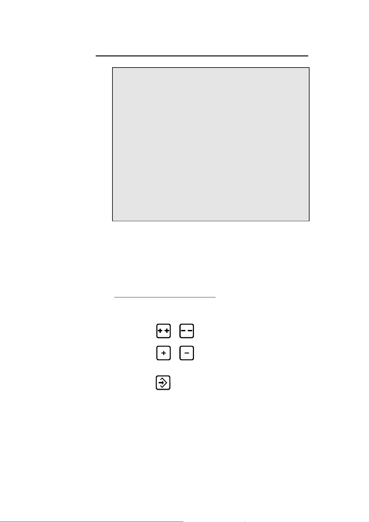
CALIBRATION OF FUNCTION F6
The calibration of function F6 is carried out in the MACHINE
PARAMETERS 14 page with the manual keys.
y Pressing the
of 1 unit and outputs the corresponding voltage on the analog output.
y Pressing the
of 10 units and outputs the corresponding voltage on the analog
output.
At each releasing of one of these keys, the voltage on the analog output
returns to 0 Volt.
1) With the cursor on the Min U D/A field, increase with the manual keys
progressively the value until the desired Min pressure is reached.
Note down this value = Min pressure.
or key increases or decreases the D/A value
or key increases or decreases the D/A value
2) With the cursor on the Max U D/A field, increase with the manual keys
progressively the value until the desired Max pressure is reached.
Note down this value = Max pressure.
3) For each of the 3 remaining intermediate points (in X %), increase with
the manual keys progressively the value until the desired pressure, that
is to say:
Pressure = Min Pressure + X % * (Max pressure – Min pressure).
SPECIAL SHEAR FUNCTIONS PAGE 51
Page 54

PARAMETRIZING OF FUNCTION F6
The parametrizing of function F6 is carried out in the MACHINE
PARAMETERS 13 page with the manual keys.
Define first the time of the pressure ramps for the upstroke and the
downstroke of the blade (P88 to P91) as well as the decompression time
(P92).
On each of the fields P83 (Minimal Blade Up Pressure), P84 (Rake Angle
Adjustment Pressure), P85 (Blade Gap Adjustment Pressure) and 86 (Blade
Up Pressure) first program a value, then:
1) When pressing a manual key:
y The pressure rises up to this programmed value.
y The corresponding digital output (Blade Up, Cutting Authorization,
SP, SN) is activated (24V).
2) When releasing the key:
y The activated digital output (Blade Up, Cutting Authorization, SP,
SN) is disactivated (0V).
y The pressure falls back to 0.
PAGE 52 MACHINE PARAMETERS DNC 60 G
Page 55

FUNCTION PRESSURE ON OR OFF (F6)
The output System Pressure must be configured to be able to use this
function.
FIELDS TO
PROGRAMME
VALUES COMMENTS
P70 F6 2
P88 0Î254
P89 0Î254
P90 0Î254
P91 0Î254
Type of management
Tempo in 1/10 of second
Tempo in 1/10 of second
Tempo in 1/10 of second
Tempo in 1/10 of second
BLADE UP OR DOWN
The management of the outputs used for the displacement of the blade is as
follows:
1. Starting:
Output SP/SN is activated. After a waiting period (defined by P88 if
the blade goes down or P90 if the blade goes up), the output System
Pressure is activated.
2. Stop:
The output System Pressure is desactived. After a waiting period
(defined by P89 if the blade goes down or P91 if the blade goes up),
the output SP/SN is desactivated.
SP OR SN OF THE AF
The management of the outputs used for SP/SN of the AF is as follows:
1. Starting:
2. Stop:
Output SP/SN is activated. After a waiting period defined by P88,
the output System Pressure is activated.
The output System Pressure is desactived. After a waiting period
defined by P89, the output SP/SN is desactivated.
SPECIAL SHEAR FUNCTIONS PAGE 53
Page 56

SHEET THICKNESS MEASUREMENT FUNCTION (F7)
With an analog sensor 0 – 10V connected to an analog input of the DNC, it is
possible to automatically measure the sheet metal thickness.
FIELDS TO
PROGRAM
VALUES COMMENTS
P70 F7 2
P72 F7 0
P79 F7 1Î254
P80 F7 1Î254
P81 F7 1Î999
P82 F7 1Î999
Type of management
AF7 analog
Min. D/A value (Teach)
Max. D/A value (Teach)
Min. programming range
(1/10mm)
Max. programming range
(1/10mm)
CALIBRATION OF FUNCTION F7
1) Without having a sheet placed under the sensor, perform the TEACH of
the min D/A value (P79 of F7).
2) Program in P81 the value 0.
3) With a sheet of maximum thickness, perform the TEACH of the max
D/A value (P80 of F7).
4) Program in P82 the maximum thickness in tenths of millimetre
If the response of the sensor is not linear, it is possible to calibrate and
parametrize F7 on a curve in 9 points (8 segments) in the MACHINE
PARAMETERS 17 page. This functionality is active if the 9 points are
defined and all different the ones from the others.
.
PAGE 54 MACHINE PARAMETERS DNC 60 G
Page 57

SHEET SUPPORT
Sheet supports are used to support metal sheets before hold-downs are
clamped (before shearing). They also help the sheared parts to slide down
onto a tray or stacker once they are cut.
The cycle of a sheet support starts after the hold-downs are tightened and
ends after they have been released (after the blade has reached the bottom
dead center).
(C1SupTol)
SW1
(C1SupTol)
SW2
(C2SupTol)
SW1
SW3
(C3SupTol)
SW2
(C2SupTol)
Position 1
Position 1
io
it
s
o
P
n
Positi
2
osition
P
2
3
n
o
Sheet supports may have 2 positions (1 high and 1 low) or 3 positions (1
high, 1 intermediate, and 1 low).
FUNCTIONALITIES PAGE 55
Page 58

CONFIGURATION
When using a sheet support, you need to define a number of inputs, outputs
and parameters.
Inputs
C1SupTol: Input used for the sensor on position 1 (high
position), regardless of the number of positions
of your support.
C2SupTol: Input used for sensor on position 2:
= low position on a 2-position support
= high position on a 3-position support
C3SupTol: Input for sensor on position 3, which is the low
position for 3 position support
Connecting 3 sensors to the numerical control is enough to indicate to the
DNC that you are using a 3-position support.
CprSeTol: CprSeTol is the short for Capteur Pression Serre
Tôle: Hold-down Pressure Sensor.
This input is optional. When active, it signals
that the metal holddowns are tightened and that
the sheet support cycle may start.
Reminder: The hold-downs are typically
controlled by parameter P36 Hold Downs
Time: the countdown for the specified time
starts as soon as the Cutting Authorization is
given.
This parameter must be configured, even when
input CprSeTol is used. In this case, the
specified time is used as a security.
However, parameter Hold Downs Time may
be used on its own, that is, even when input
CprSeTol is not connected.
Outputs
SupTolUp: Output that controls all upward moves of the
sheet support.
SupTolDn: Output that controls all downward moves of the
PAGE 56 MACHINE PARAMETERS DNC 60 G
sheet support.
Page 59

STSingle: This output switches to 1 when the output
SupTolDn becomes active, and switches to 0
when SupTolUp becomes active.
This ouput acts as a unique control that sends the
sheet support on low position and holds it down
for the required duration (in supports where the
high position is the default, eg in a monostable
actuator).
Sheet Support Up
(Output SupTolUp)
Sheet Support Down
(Output SupTolDn)
Sheet Support Single
(Output STSingle)
PARAMETERS
All machine parameters dedicated to sheet support are listed in the table
below.
For more information on these parameters, please refer to section Sheet
Support
on page 35 of this manual.
P115 SHEET SUPPORT
START DELAY
P106 SHEET SUPPORT
TIME DOWN
P106b SECURITY DELAY
DOWN
P102 SHEET SUPPORT
TIME
P105 SHEET SUPPORT
TIME UP
P107 RETURN SHEET
SUPPORT AT TDC
SCREEN DISPLAY (FOR THE OPERATOR)
This icon displays on the operator screen whenever the
SupTol field is available, that is, whenever a sheet support is
configured on your DNC.
When the value in this field is 1, the sheet support is activated
for the current sequence.
The value in this field only applies to the current sequence: it
may change at every sequence.
FUNCTIONALITIES PAGE 57
Page 60

CYCLE OF A 2-POSITION SHEET SUPPORT
A 2-position sheet support may be configured in several ways:
- with 2 sensors (C1SupTol and C2SupTol) controlling the actual
position of the support,
- with 2 specified time parameters P105 and P106: the actual position of
the support is not controlled,
- with 1 or 2 sensors (C1SupTol / C2SupTol) and 1 or 2 specified time
parameters (P105 / P106).
This section explains how the most common configurations work.
Other configurations may work just as well. However, they are not
documented here.
Configuration 1: 2 sensors (C1SupTol and C2SupTol)
In this configuration, the position of the sheet support is controlled by 2
sensors C1SupTol and C2SupTol. Parameters P 103 and P106 are not set.
(SupTol) = 1
At the beginning of the work cycle, the sheet support is always in high
position.
As soon as the DNC receives the signal for cutting authorization (or cut
order), the countdown of parameter P115 (SHEET SUPPORT START
DELAY) starts. At the end of the countdown, the sheet support goes down to
position 2 (low), and activates the sensor located at that position.
Once the blade reaches BDC and the support is in position 2, the countdown
of the specified time SHEET SUPPORT TIME (P102) begins.
If the value in the SupTol field of the next sequence is 1, the support will go
back to position 1 (high) at the end of the countdown. If the value is 0 or
undefined, the support remains in position 2 (low).
PAGE 58 MACHINE PARAMETERS DNC 60 G
Page 61
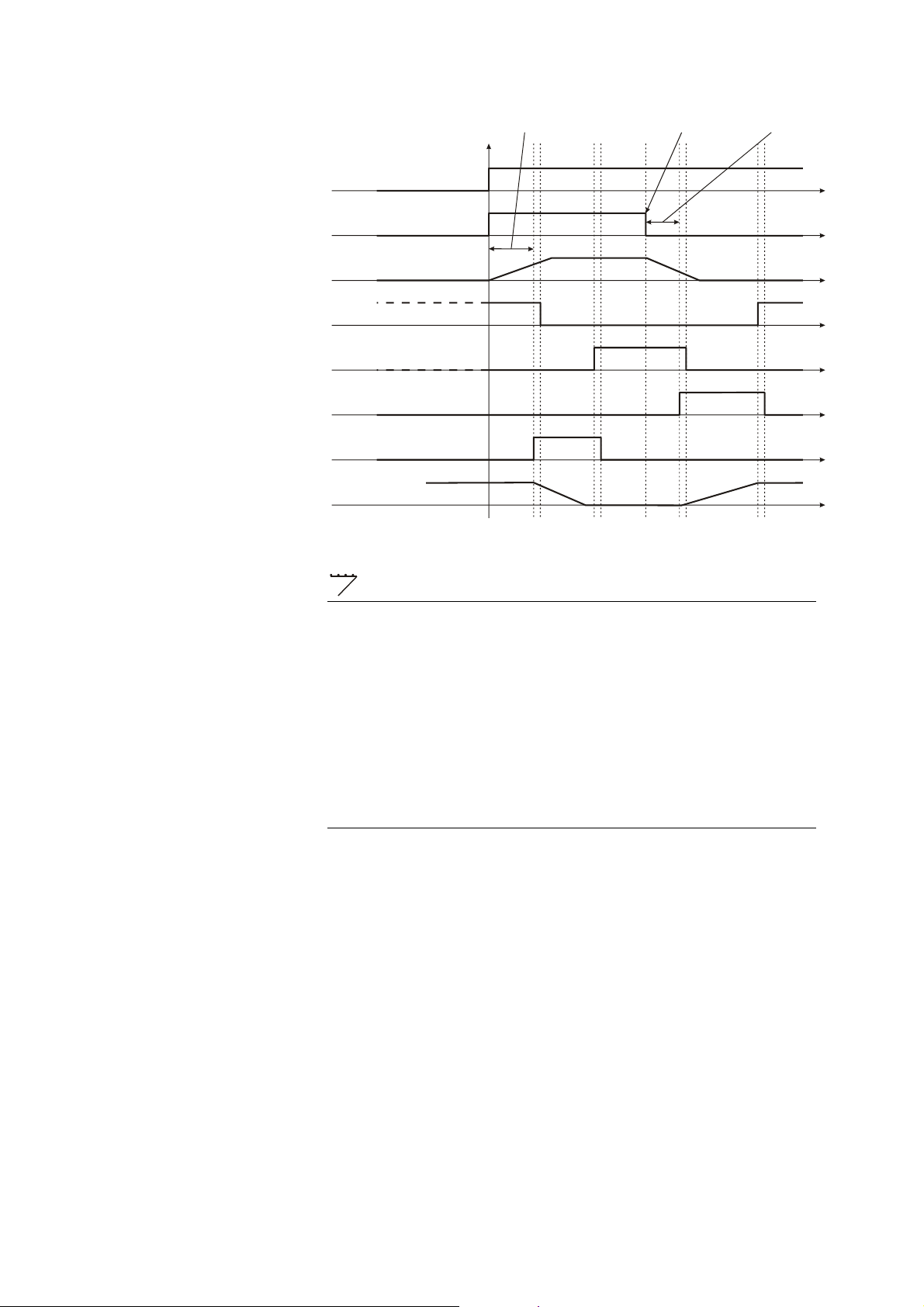
S
S
Pedal
Cuttin Authorization
Hold-down Pressure
Sheet Support Position 1
(Input C1SupTol)
Sheet Support Position 2
(Input C2SupTol)
Sheet Support Up
(Output SupTolUp)
Sheet Support Down
(Ouput SupTolDn)
Sheet Support
Position
heet Support
Start Delay P115
BDC
heet Support
Time P102
(SupTol) = 0 or Undefined
At the beginning of the working cycle, the support goes down to position 2
(low).
The support then remains in the low position until the blade reaches BDC.
At that point, the DNC checks whether the support is used in the next
sequence (SupTol = 1). If it is, the support goes back to position 1 (high)
after SHEET SUPPORT TIME. If not, it stays in position 2 (low).
Configuration 2: 2 Parameters P105 and P106
In this configuration, the sheet support is controlled by parameters P105 and
P106. (The DNC does not know the exact location of the support, but
extrapolates it based on the statuses of these 2 parameters).
The operating mode of the support as controlled by the time parameters P105
and P106 is very similar to that controlled by 2 sensors, with the following
exceptions:
• The sheet support stops going up when the time specified in P105
(TEMPO SUPPORT TOLE UP) has expired. (Unlike
Configuration 1, there is no sensor signal C1SupTol).
• The support stops going down when the time specified in P105
(TEMPO SUPPORT TOLE UP) has expired. (Unlike
Configuration 1, there is no sensor signal C2SupTol).
FUNCTIONALITIES PAGE 59
Page 62

S
p
S
S
e Do
06
Sheet Support
Start Delay P115
BDC
heet Support
Time P102
Pedal
Cutting Authorization
Hold-down Pressure
Sheet Support Up
(Output SupTolUp)
Sheet Support Down
(Output SupTolDn)
Sheet Support
Position
Sheet Support
Time Down P106
Sheet Support
Time U
P105
Configuration 3: 1 Sensor C1SupTol and Parameter P106
The sheet support is controlled by 1 sensor (C1SupTol) and by parameter
P106 (SHEET SUPPORT TIME DOWN).
The support stops going down when the time specified in parameter 106
(SHEET SUPPORT TIME DOWN) has expired.
The DNC has no control of the exact location of the support when it is
lowered. The support stops going up when sensor C1SupTol becomes
active.
heet Support
Time P102
Pedal
Cutting Authorization
Hold-down Pressure
Sheet Support Position 1
(Input C1SupTol)
Sheet Support Up
(Output SupTolUp)
Sheet Support Down
(Ouput SupTolDn)
Sheet Support
Position
heet Support
Start Delay P115
BDC
Sheet Support
Tim
wn P1
PAGE 60 MACHINE PARAMETERS DNC 60 G
Page 63

S
S
o
06b
Configuration 4: 2 Parameters P105 and P106 + 1 Sensor C1Suptol
In this configuration, parameter P106b is set. It is used as an additional
security (“watchdog”) when the support starts going down.
The sheet support must leave (and de-activate) sensor C1SupTol before the
time specified in P106b (SECURITY DELAY DOWN) has expired.
If it doesn’t, the work cycle is interrupted and a pop-up appears on the
screen.
Parameter P105 (SHEET SUPPORT TIME UP) acts as a security when the
support rises.
heet Support
Time P102
Pedal
Hold-down Pressure
heet Support
Start Delay P115
BDC
Sheet Support Position 1
(Input C1SupTol)
Sheet Support Up
(Output SupTolUp)
Sheet Support Down
(Output SupTolDn)
Sheet Support
Position
Security Delay
D
wn P1
Sheet Support
Time Down P106
CYCLE OF A 3-POSITION SHEET SUPPORT
Whenever you set the 3 inputs C1SupTol, C2SupTol and C3SupTol the
DNC knows that a 3-position sheet support is being used.
(SupTol) = 1
Sheet Support
Time Up P105
At the beginning of the work cycle, the support goes up to position 1 (high).
As soon as the DNC receives the signal for cutting authorization (or cut
order), the countdown of the time specified in parameter P115 (SHEET
SUPPORT START DELAY) starts. At the end of the countdown, the sheet
support goes down to position 2 (intermediate), and activates the sensor
located at that position.
Once the blade reaches BDC, the support goes down to position 3 (low),
while the blade goes back up.
FUNCTIONALITIES PAGE 61
Page 64

When the support reaches position 3 and activates sensor C3Suptol, the
countdown of the specified time SHEET SUPPORT TIME (P102) begins.
If the value in the SupTol field of the next sequence is 1, the support will go
back to position 1 (high) at the end of the countdown. If the value is 0 or
undefined, the support remains in position 2 (low).
Pedal
Cutting Authorization
Hold-down Pressure
Sheet Support Position 1
(Input C1SupTol)
Sheet Support Position 2
(Input C2SupTol)
Sheet Support Position 3
(Input C3SupTol)
Sheet Support Up
Sheet Support
Start Delay P115
BDC
Sheet Support Down
(Output SupTolDn)
Sheet Support
Position
Sheet Support Time P102
(SupTol) = 0 or Undefined
At the beginning of the work cycle, the support goes down to position 3
(low).
The support then remains in its lowest position until the blade reaches BDC.
At that point, the DNC checks whether the support is used in the next
sequence (SupTol = 1). If it is, the support goes back to position 1 (high)
after SHEET SUPPORT TIME. If not, it remains in position 3 (low).
MANUAL MODE
When the cursor is on the SupTol field, pressing on one of the following
keys
To stop the support at any time, simply release the key.
PAGE 62 MACHINE PARAMETERS DNC 60 G
will cause the sheet support to go up or down.
Page 65

When the cursor is on the Cut width field, pressing on
or on will cause both the blade and the sheet support to go
down. However, pressing on
sheet support.
ANTI-TWIST DEVICE
An anti-twist device is a piece of equipment that will prevent the sheet from
twisting when you cut lengthy pieces of metal.
When you start cutting, the device is in high position and holds up the metal
sheet. It is then lowered to support the sheet during cutting.
The DNC 60 G16 controls this type of device in the same way as a 2-position
sheet support (without sensors), that is, with specified times (for more
details, please refer to section Sheet Support on page 55).
INPUTS/OUTPUTS
In order to implement an anti-twist device, you must configure the 2
following outputs:
or on won’t have any effect on the
ATwistUp This output controls all upward moves of the
anti-twist device.
ATwistDn This output controls all downward moves of the
anti-twist device.
You do not need to configure any input.
PARAMETERS
All machine parameters dedicated to an anti-twist device are listed in the
table below.
For more information on these parameters, please refer to section Anti-Twist
Devi
ce on page 36 of this manual.
P116 A-TW START
DELAY
P110 A-TW TIME
DOWN
P109 A-TW TIME
P108 A-TW TIME UP
P111 RETURN A-TW
AT TDC
FUNCTIONALITIES PAGE 63
Page 66

A-TW DEVICE CYCLE
Since the anti-twist device is not equipped with sensors, the DNC has no
information on its position. The device is managed by 2 parameters: P108
and P110.
These parameters are similar to P105 and P106 in the case of a sheet support.
(For details, please, refer to page 63 in this manual.)
SCREEN DISPLAY (FOR THE OPERATOR)
The 'A-TW' field displays on the sequence and EASY CUT pages whenever
the anti-twist feature is on.
To set the anti-twist feature, enter the digit 1 in the field.
MODE MANUEL
Pressing one of the following keys
on the A-TW field will cause the anti-twist device to go up or down. To stop
the device at any time, simply release the key.
with the cursor
PAGE 64 MACHINE PARAMETERS DNC 60 G
Page 67

FUNCTIONALITIES
VISUALIZATION OF THE INPUTS/OUTPUTS PAGES IN
CYCLE
In order to facilitate the starting and the follow-up of the Inputs/Outputs
state, it is possible to visualize the Inputs/Outputs pages during the machine
cycle.
As soon as the machine is in AUTOMATIC or SEMI-AUTOMATIC mode,
a first pressure on the
Inputs/Outputs page. The following three pressures on this same key provoke
the display of the next 3 Inputs/Outputs pages.
In order to return to the original page, the
key provokes the display of the 1st
key is to be pressed 4 times.
INPUT CLEARANCE X
The clearance of the backgauge X towards the back of the machine allows to
avoid the spin of the sheet when a cut is only of low width.
This functionality is active as soon as the input Clearance X is
configurated.
In SEMI-AUTOMATIC or AUTOMATIC mode, as soon as the blade goes
down, or in MANUAL mode:
- An ascending front on this input provokes the sending of X to
LSW+.
- A descending front on this input provokes the standstill of X.
BACKGAUGE FOLDAWAY X
The backgauge foldaway allows to cut sheets longer than its max. limit
switch.
In the MACHINE PARAMETERS page, the 2 following parameters must
be configurated:
y P94 = PARK DISTANCE (see figure).
y P95 = CRAWL DISTANCE (see figure).
P94 defines the safety distance from the max. limit switch where the gauge
is retracted.
The PARK TARGET (= LSW max. – P94) is the absolute value from which
the gauge is completely retracted.
INPUT/OUTPUT CONFIGURATION PAGE 65
Page 68

P95 defines the transition distance between the normal position of the
backgauge and its retracted position.
The CRAWL TARGET (= park target – P95) is the absolute maximum
value of the backgauge for a normal use.
LSW
Min.
CRAWL TARGET
P95 =
CRAWL Dist.
P 94 =
PARK Dist.
PARK TARGET
If parameters P94 and P95 are configurated, the backgauge retraction is
active. In this case, if the value X MEM is superior to the CRAWL
TARGET, that one is set on Undef and the axis is sent to its max. limit
switch. As soon as the PARK TARGET is reached, the axis stands still.
If furthermore P97 (LS/HS X COMMUTATION) is configurated with value
1, then:
LSW
Max.
y at each entry of X in the retraction zone (= P94 + P95), the DNC will
pass in LS on X.
y at each outgoing of X from the retraction zone (= P94 + P95), the
DNC will pass in HS on X.
CAUTION: To use this functionality (P97), it is recommended to not
configure the LSX input.
PAGE 66 MACHINE PARAMETERS DNC 60 G
Page 69

M
M
M
P95 = Dist
COTE DE RAMPE
COTE DE PARC
RAMPE
P94 =
Dist PARC
FC
Min.
CLEARANCE OF THE BACKGAUGE X
When the backgauge X is not programmed in the sequence,
it remains in its position;
except if the P94 parameter is configured with an unspecified value
and that the P95 parameter is not defined. In this case, it is sent
towards LSW+.
FC
Max .
INPUT/OUTPUT CONFIGURATION PAGE 67
Page 70

HYDRAULIC FOLDAWAY OF BACKGAUGE X
The retraction of the backgauge is activated by a hydraulic cylinder.
To activate this functionality, must be programmed:
y P94 (PARK DISTANCE)
y P95 (CRAWL DISTANCE) = 0
y P96a (HYDRAULIC FOLDAWAY TIME IN)
y P96b (HYDRAULIC FOLDAWAY TIME OUT)
y P96c (SECURITY DELAY)
y P96d (HYDRAULIC FOLDAWAY RISE PRESSURE)
Input / Output
• IN BG Dn: Input for the foldaway down sensor. This sensor must be in
the park zone where it will stop the movement of the backgauge before
the rise. The stop when the backgauge goes down is done by this
sensor. (This input must be configurated.)
• IN BG Up: Input for the foldaway up sensor. This sensor indicates the
up position when the backgauge is retracted. (This input can be
configurated.)
• OUTBg Dn: Output to active the backgauge going down. (This output
must be configurated.)
• OUTBg Up: Output to active the backgauge rise. (This output must be
configurated.)
Remark: If the IN BG Dn input isn’t activated and the IN BG Up input
isn’t configurated, the backgauge isn’t necessarily at the up
position for the software.
Functionnement
If X MEM is not defined and the foldaway takes place (entry of X in PARK
zone), after the stopping of the axes and the auxiliary functions the DNC will
supply a pressure during the time defined by P96d, allowing to move up the
backgauge. The pressure stops with the help of the activation of the IN Bg
Up input (if it is configured) or by the end of the temporization defined by
P96a. If the temporization has finished before the input is active (and
configured), a message is displayed with a pop-up.
PAGE 68 MACHINE PARAMETERS DNC 60 G
Page 71

0
M
M
P96 = Tempo
escamotage hydraulique
Pression
t
M
P94 = Dist.
PARC
FC
Min.
COTE DE PARC
P95 = Dist.
RAMPE =
INPUT SET PRESSURE
This functionality is active as soon as the input SetPressure is
configurated.
On the ascending front of this input:
If the current pressure is zero (i.e. if no other pressure is active so far);
then upstroking in pressure towards the Pressure Blade up.
On the descending front:
FC
Max.
M
If the current pressure has been activated by the ascending front of
this input:
then return to Pressure zero.
INPUT/OUTPUT CONFIGURATION PAGE 69
Page 72

FACILITATED UP/DOWN MANIPULATION OF THE BLADE
This functionality facilitates the calibration of the auxiliary function AF3
(cutting length).
With the cursor in the field Min or Max D/A AF3 (= P79 or P80):
y Each pedal pressing provokes the upstroking or the downstroking of
the blade.
y Each pedal releasing provokes the falling back of the outputs
Blade Up or Blade Down.
If the duration between two successive pedal pressings is longer than 2
seconds, then the direction of the blade movement is inversed, otherwise the
direction remains the same.
To indicate the direction of the next movement, the messages Next UP and
Next DOWN are displayed 2 seconds after the last pedal pressing.
PAGE 70 MACHINE PARAMETERS DNC 60 G
Page 73

INTERNAL BACKUP (SAVE)
A machine parameter and tools backup is available in the internal memory. A
restoration can also be performed from this same internal memory.
This functionality is exclusively used by the manufacturer to memorize the
parameters and tools state, at the time of the delivery of the machine.
In the event of problems, this will allow the operator to easily reload the
original parameters and/or delivered tools. This can be done without
connecting the DNC to a PC.
Note: Only the last compatible backup can be restored.
The memory quantity is limited. Each save takes up memory space (no
rewrite possible) and the number of backups depends on the software version
and the number of tools.
If this memory is full, it can only be deleted by reinstalling the boot software
(See further). This is an operation which must only be done by a qualified
and trained person.The number of backup saves available (generally 1 to 2)
is enough for the correct use of this function:
Backup are usually performed:
• When the machine leaves the factory.
• When the machine is set up in workshop
• When a technician is called to re-configure a machine.
Internal backup (saving) of the PMs and tools
To save the machine parameters and tools, go to the TRANSFER RS232
page from the main menu.
DNC <-> PC STATUS STOP PA
TRANSFER 1 1 DNC --> PC
2 PC --> DNC
3,4 TEST LIAISON 1 2
7 FLASH
8 EXT KEYBOARD
10 ARDIS CONNEXION
11 INTERNAL BACKUP
12 INTERNAL RESTORE
Quantity of free backup memory 97 %
-- RS232 PARAMETERS - Baud rate 57600 Stop 1.0
Parity odd (1) EVEN (0) _ Bits 8
• Select 11 INTERNAL BACKUP
INPUT/OUTPUT CONFIGURATION PAGE 71
Page 74

2
DNC <-> PC STATUS STOP PA
TRANSFER 1 1 DNC --> PC
2 PC --> DNC
3,4 TEST LIAISON 1 2
7 FLASH
8 EXT KEYBOARD
10 ARDIS CONNEXION
Internal backup
11 INTERNAL BACKUP
12 INTERNAL RESTORE
Quantity of free backup memory 97 %
0 = Abort
1 = Save machine parameters
= Save tools
-- RS232 PARAMETERS - Baud rate 57600 Stop 1.0
Parity odd (1) EVEN (0) _ Bits 8
• Choose the operation by pressing the 0, 1 or 2 key.
The pop-up closes.
• The message value ? is displayed at the top right of the screen (the
same as for changing to access level 2 or 3).
Enter the level 4 code for the machine parameters or the 217 code
for the tools.
• Press the
key.
DNC <-> PC STATUS EXECUTE
TRANSFERT 1 1 DNC --> PC
2 PC --> DNC
3,4 TEST LIAISON 1 2
7 FLASH
8 EXT KEYBOARD
10 ARDIS CONNEXION
11 INTERNAL BACKUP
12 INTERNAL RESTORE
Quantity of free backup memory 93 %
-- RS232 PARAMETERS - Baud rate 57600 Stop 1.0
Parity odd (1) EVEN (0) _ Bits 8
When the backup save has finished, the EXECUTE message and the new
free memory percentage are displayed.
PAGE 72 MACHINE PARAMETERS DNC 60 G
Page 75

INTERNAL RESTORATION OF PMS AND TOOLS
This functionality allows the owner of the machine to restore the original
factory parameters. This can be used in the event of problems by the
operatorm, assisted by the manufacturer/dealer.
The parameters restoration will replace the current contents of the DNC by
the last parameters save (generally performed by the manufacturer upon
machine delivery).
The tools restoration will replace all tools data which have the same number.
The tools which have a different number to those in the backup are not
affected by the restoration.
Example: The punches number s 1 and 2 have been saved.
The user has modified the data of the punches 1 and 2, and has
added the punches 12, 14 and 15.
At the moment of the restoration, the value of the data of the
punches 1 and 2 will be replaced by those of the saved tools.
The punches 12, 14 and 15 aren’t affected.
Only the last compatible backup can be restored.
To restore the machine parameters and tools, go to the TRANSFER RS232
page from the main menu.
DNC <-> PC STATUS STOP PA
TRANSFER 11 1 DNC --> PC
2 PC --> DNC
3,4 DATA LINK TEST 1 2
7 FLASH
8 EXT KEYBD
10 ARDIS CONNECTION
11 INTERNAL BACKUP
12 INTERNAL RESTORE
Quantity of free backup memory 93 %
-- RS232 PARAMETERS - Baud rate 57600 Stop 1.0
Parity odd (1) EVEN (0) _ Bits 8
• Select 12 INTERNAL RESTORE
INPUT/OUTPUT CONFIGURATION PAGE 73
Page 76

DNC <-> PC STATUS STOP PA
TRANSFER 11 1 DNC --> PC
2 PC --> DNC
3,4 DATA LINK TEST 1 2
7 FLASH
8 EXT KEYBD
10 ARDIS CONNECTION
Internal restore
11 INTERNAL BACKUP
12 INTERNAL RESTORE
Quantity of free backup memory 93 %
0 = Abort
1 = Restore machine parameters
-- RS232 PARAMETERS - Baud rate 57600 Stop 1.0
Parity odd (1) EVEN (0) _ Bits 8
• Select the operation to be performed by pressing the 0, 1 or 2 key.
• The pop-up closes.
• The message value ? is displayed at the top right of the screen (the
same as for changing to access level 2 or 3).
Enter the code 718 to restore the machine parameters or the tools.
• Press the
key.
DNC <-> PC STATUS STOP PA
TRANSFER 11 1 DNC --> PC
2 PC --> DNC
3,4 DATA LINK TEST 1 2
7 FLASH
8 EXT KEYBD
Restore successfully done
10 ARDIS CONNECTION
11 INTERNAL BACKUP
12 INTERNAL RESTORE
Press any key to continue
Quantity of free backup memory 93 %
-- RS232 PARAMETERS - Baud rate 57600 Stop 1.0
Parity odd (1) EVEN (0) _ Bits 8
When the restoration has finished, a pop-up is displayed.
PAGE 74 MACHINE PARAMETERS DNC 60 G
Page 77

INPUT/OUTPUT CONFIGURATION
The configuration of the inputs/outputs of a DNC consists in assigning a
software function (see paragraph Definition of inputs/outputs) t
input or output of the numerical control.
The inputs and outputs, when they are not being used, have the following
designations in the input/output list:
Digital Analogical Voltage
F dig 1 Pot F1 A analog 1
F dig 2 Pot F2 A analog 2
. . A analog 3
. .
. .
F dig 20 Pot F8
CONFIGURABLE AXES AND FUNCTIONS
o a given
Availability of an axis or a function is in direct relationship with the
hardware. The DNC 60 G16 can handle a maximum of 4 axes. It is therefore
not possible to configure all the axes which are available in the software, but
only 4 among them. The same is true for the auxiliary functions within the
limits of the available inputs/outputs.
AXES
The configuration (which will cause the axis to appear on the CRT) can be
achieved by programming the limit switches (+,-) of the relevant axis.
X1-X2
X
X4 to X6
In the N2X parameters pages press the manual key
the available axes
X1 X2 X X4 X5 X6
Front gauges
Backgauges
Auxiliary functions
or to display
INPUT/OUTPUT CONFIGURATION PAGE 75
Page 78

FUNCTIONS
These functions assign an output as soon as the function is being used.
For instance, if the X4 axis is used, the output X4 in position will
automatically be assigned.
X used alone
X4 in position
X5 in position
X6 in position
Leg X1
Leg X2
Leg X
AF1 to AF8
Output signalling that the DNC functions in
"backgauge mode". This means that X1 and X2
are not programmed in the current sequence.
Output signalling that the X4 axis is in
position.
as above, but for X5.
as above, but for X6.
Output activating the leg code of the X1 axis.
Output activating the leg code of the X2 axis.
Output activating the leg code of the X axis.
Auxiliary functions assigned according to the
AF configuration table.
PAGE 76 MACHINE PARAMETERS DNC 60 G
Page 79

DEFINITION OF INPUTS/OUTPUTS BY DEFAULT
INPUTS
– PEDAL = Pedal
– TDC max = TDC max (Sensor)
– Fly Cut = Flying Cut
– IZ X = Index Zone Signal Axis X
INPUT CONFIGURATION IGNORE
SEARCH CONFIGURATION BY DEFAULT _
--- MB6 J10 --- 10111100
01: Pedal ÇÈ 02: TDC max ÇÈ
03: Fly Cut ÇÈ 04:
05: 06:
07: 08: IZ X ÇÈ
--- MB6 J11 -- 01: 02:
03: 04:
05: 06:
07: 08:
(must remain blank)
INPUT CONFIGURATION IGNORE
SEARCH CONFIGURATION BY DEFAULT _
--- MIO J10 -- 01: 02:
03: 04:
05: 06:
07: 08:
--- MIO J11 -- 01: 02:
03: 04:
05: 06:
07: 08:
INPUT/OUTPUT CONFIGURATION PAGE 77
Page 80

OUTPUTS
– CutAuth = Cutting Authorization
– F1Dig SP / SN = Digital output AF1 (1
– F2Dig SP / SN = Digital output AF2 (Rake angle)
– F5Dig SP / SN = Digital output AF5 (2
– SP X = SP Signal Axis X
– SN X = SN Signal Axis X
With the aim to simplify the wiring in the electrical cabinet and to avoid a
systematic electromechanical relayer on the digital outputs, it is possible to
double the following outputs:
y Cutting authorization (= Blade down)
y Upstroking of the blade
y All auxiliary functions outputs
In order to establish a double output, it is sufficient to configure the second
output. It takes the same name as the first one and finishes with the letter B.
st
Blade gap)
nd
Blade gap)
OUTPUT CONFIGURATION IGNORE
SEARCH CONFIGURATION BY DEFAULT _
--- MB6 J10 --- 10100000
09: CutAuth 10: Blade Up
11: F1Dig SP 12: F1Dig SN
13: F2Dig SP 14: F2Dig SN
15: F5Dig SP 16: F5Dig SN
--- MB6 J11 --- 00000000
09: 10:
11: 12:
13: 14:
15: SP X 16: SN X
PAGE 78 MACHINE PARAMETERS DNC 60 G
Page 81

(must remain blank)
OUTPUT CONFIGURATION IGNORE
SEARCH CONFIGURATION BY DEFAULT _
--- MIO J10 ---
09: 10:
11: 12:
13: 14:
15: 16:
--- MIO J11 ---
09: 10:
11: 12:
13: 14:
15: 16:
INPUT/OUTPUT CONFIGURATION PAGE 79
Page 82

CONFIGURATION OF DIGITAL INPUTS/OUTPUTS
MACHINE PARAMETERS page, key or .
After a deleting of the machine parameters zone the I/O configuration is
reinitialized with its original default values.
Attention: On this machine we have only 16 I/O hardware, consequently
To modify:
y Place the cursor on the field to be modified.
y Select with keys
the I/O which it is possible to affect on this machine.
Remark: For the AF the extension, which can go from D0 to D7, SN,
To find the original configuration again:
It is at any time possible to find the default I/O configuration again. For that:
y Program in the SEARCH CONFIGURATION BY DEFAULT field
the value 1.
y Press the SEARCH key
nd
configurable I/O pages are blank by default and have to
the 2
remain blank. (They must in no case be modified).
and the desired input or output among
SP, PV, is to specify.
For the supplementary legs only the extensions D0, D1, D2
make sense and are controlled.
.
The message TEACHED appears.
The CONFIGURATION 8 I/O field of the MACHINE PARAMETERS 01
page must be programmed with value 1.
PAGE 80 MACHINE PARAMETERS DNC 60 G
Page 83

CONFIGURATION OF ANALOGIC INPUTS/OUTPUTS
Reminder: On this machine there are:
– 4 analogic inputs
– 2 analogic outputs: the first one is reserved to the supply
voltage of X and the second one to the pressure regulation
if AF6 is parametrized in pressure mode.
For the analogic inputs, the address allocation is automatically made in
dynamic manner when programming the AFs.
Here a list of the different possibility :
F2/F3 WITH ONLY ONE POTIENTOMETER : PM 70 PM 72 INPUT
ORDER
F1 1ST BLAD GAP 2 1 1ST J7_PIN_2
F2 CUTTING ANGLE 2 1 2ND J7_PIN_1
F3 CUTTING LENGTH 2 0 2ND J7_PIN_1
F5 2ND BLAD GAP 2 1 3RD J8_PIN_2
F7 SHEET TIGHTNESS
MEASURE
F8 ONLY IF
NOT F7
F2/F3 WITH 2 POTIENTOMETERS : PM 70 PM 72 INPUT
F1 1ST BLAD GAP 2 1 1ST J7_PIN_2
F2 CUTTING ANGLE 8 1 OU 0 2ND J7_PIN_1
GENERIC _ 1 4TH J8_PIN_1
2 0 4TH J8_PIN_1
ORDER
WIRING
WIRING
F3 CUTTING
ANGLE/LENGTH
F5 2ND BLAD GAP 2 1 4TH J8_PIN_1
F7 ONLY IF
NOT F5
F8 ONLY IF
NOT F5 AND F7
INPUT/OUTPUT CONFIGURATION PAGE 81
SHEET TIGHTNESS
MEASURE
GENERIC _ 1 4TH J8_PIN_1
8 1 3RD J8_PIN_2
2 0 4TH J8_PIN_1
Page 84

MANAGEMENT OF THE ACCESS LEVELS BY
EXTERNAL KEY
If the use of the external key is defined in the machine parameters, the access
levels are managed by the external key. The passwords are no more active.
The use of the external key is defined by the parameter Key = 1 and by the
use of the inputs KEY 0 and KEY 1.
Input
KEY 0
OFF OFF
ON OFF
OFF ON
ON ON
Input
KEY 1
Pos.
key
0
1
2
3
PAGE 82 MACHINE PARAMETERS DNC 60 G
Page 85

MACHINE MESSAGES
y In MACHINE PARAMETERS (page 12):
y In INPUT CONFIGURATION page:
y In OPERATION:
M MACHINE PARAMETERS -12- IGNORE
A 01 A FE
C 02 B OU
H 03
I 04
N 05
E 06
07
M 08
E 09
S 10
S 11
A 12
G 13
E 14
S 15
You have the possibility to define 15 messages, which can each be
composed of 2 words with 15 characters.
You have the possibility to affect 4 inputs (D0MesMac to
D3MesMac) which offer 15 possible state combinations, each of these
states corresponds to a message to be displayed.
At each state changing on one of the inputs (D0MesMac to
D3MesMac), the corresponding message is displayed immediately.
(You also have a short history of the last 4 displayed messages at the
bottom of the page).
INPUT/OUTPUT CONFIGURATION PAGE 83
Page 86

This page has been left blank intentionally.
PAGE 84 MACHINE PARAMETERS DNC 60 G
Page 87

INDEX
Cut on middle, 33
A
Access levels
Management by external key, 80
Access to EasyCut mode, 16
Advanced stop, 24
Alphanumeric characters, 21
Analogue, 23
B
B
ackgauge foldaway X, 65
Baud, 17
BCC, 19
BDC, 46
Blade Down
acc. time, 27
dec. time, 27
Blade gap, 41
Blade gap extended, 29
Cutting length, 43, 47, 49
Cutting length calculation, 46
Cutting pressure, 26
Cutting pressure calibration, 28
Cycle Type, 16
D
Dat
a, 18
Decompression time, 28
Default thickness, 17
Delay opening hold-downs, 37
Digital, 22
DSR, 18
Duration opening hold-downs, 37
E
ELECTRICAL BLADE GAP, 27
Blade gap pressure, 27
Blade manipulation, 70
Blade Up
acc. time, 28
dec. time, 28
Blade Up gain, 27
Blade up pressure, 26
Blade Up pressure, 27
C
C
alibration, 23, 42, 47, 49, 51, 54
cutting length F3, 45
rake angle F2, 44
Checksum, 19
Choice of language, 6
Clearance X, 67
Copyright & License agreement, 6
Crawl distance, 30, 65
Crawl target, 30, 66
External START, 22
F
Fi
xed point blade, 16
Flying Cut, 50
Fn, 21
Functionalities, 65
H
Hy
draulic retraction, 68
I
I/
O Visualization in run, 38
Independent function, 22
Input clearance X, 65
Inputs/Outputs state, 65
Internal backup, 71
CTS, 18
INDEX PAGE 85
Page 88

J
Jitter Erro
r, 12
K
Key
, 6
external, 80
Key 0 blocks utilization, 39
L
Language, 6
LS, 24
M
M
anual
dec. time, 28
Master, 6
Material, 17
Maximum range, 25, 26
Message
RUN, 19
Rake angle calculation, 46
Rake angle pressure, 26
Resolution, 9
Return Sheet Support at TDC, 35, 36
Rotation point, 16
S
Safety in
structions, 6
Security Delay Down, 34
Sensor Distance TDC max, 29
Sequentiel sending FAs, 37
Sheet Support, 55
Sheet Support, 34
Sheet Support Start Delay, 35
Sheet Support Time, 34, 36
Sheet Support Time Down, 34, 36
Sheet Support Time Up, 34, 36
Sheet thickness measurement, 54
Show all machine parameters, 38
Minimum range, 25, 26
N
Ni
bbling mode, 38
O
Overrun, 24
P
Parity, 1
8
Park distance, 30, 65
Park target, 30, 65
Pic, 6
Pressure all or nothing, 53
Pressure ramps, 51
Print all machine parameters, 38
Protocol, 18
Software
Master version, 6
START
external, 22
Stop bits, 18
Stop Q product reached, 20
T
TDC
, 46
Teach, 21
Time, 25
Toggle mode level 3/2/3, 37
Tolerance, 25
Transmission speed, 17
U
Un
interruptible cut, 38
R
R
ake angle, 16, 43
PAGE 86 INDEX
V
Versi
on
Software Master, 6
Page 89

Voltage, 23
X
X B
ackgauge foldaway, 30
INDEX PAGE 87
 Loading...