

Page 1

CYCAD
User Guide
CYBELEC SA Tel. ++ 41 24 447 02 00
RUE DES UTTINS 27 Fax ++ 41 24 447 02 01
CH - 1400 YVERDON-LES-BAINS E-Mail: info@cybelec.ch
SWITZERLAND
V-DOC-CYCAD3-EN
Page 2

Information in this document is subject to change without notice, and does not represent a
commitment on the part of CYBELEC SA. The software described in this document is furnished under
a license agreement or nondisclosure agreement. The software may be used or copied only in accordance
with the terms of the agreement. It is against the law to copy the software on any medium except as
specifically allowed in the license or nondisclosure agreement.
Copyright CYBELEC SA. 1991
All rights reserved.
Important:
This notice explains normal and standard programming operations for the numerical control.
In view of the fact that numerical controls can be equipped with configurable functions by the press
manufacturer for his own specific purposes, please refer to the manufacturer-supplied complementary
instructions regarding the programming of these functions.
Arcnet
CYBELEC
Ethernet
IBM
are registered trade marks of the International Business Machines Corporation.
MS-DOS
MS-Windows
Novell Netware
Windows NT
is a registered trade mark of Datapoint Corporation.
is a registred trademark of CYBELEC SA.
is a registered trade mark of Xerox Corporation.
, PC/AT , PC Network , Token Ring Network
is a registered trade mark of Microsoft Corporation.
is a registered trade mark of Microsoft Corporation.
is a registered trade mark of Novell, Incorporated.
is a registered trade mark of Microsoft Corporation.
Page 3

AFETY AND MAINTENANCE INSTRUCTIONS
S
The operator must be trained for working with the
!
machine on which the numerical control is installed.
!
Improper use of the numerical control can cause
heavy damage on equipment and/or injuries to
people.
!
Modification of machine parameters can cause
important material damage or lead to irregular
product quality.
The rear panel may only be removed by a qualified
!
technician (danger of electrocution).
!
Do not expose the numerical control to excessive
humidity so as to avoid any risk of electrocution and
any deterioration of the equipment.
Make sure the numerical control is disconnected
!
from the mains power before carrying out any
cleaning. Do not use liquids based on alcohol or
ammoniac.
In case of malfunction of the numerical control, call a
!
technician.
Do not expose the numerical control to direct sun
!
rays or any other heat source.
Do not place the numerical control in the
!
neighbourhood of magnetic equipment such as
transformers, motors or devices which generate
interference (welding machines, etc.)
Replace fan filters at regular intervals so as to avoid
!
overheating.
SAFETY AND MAINTENANCE INSTRUCTIONS PAGE I
Page 4

This page has been left blank intentionally.
PAGE II PC 1200 / CYCAD
Page 5

21.03.2003 V. 3.1
CONTENTS
SAFETY AND MAINTENANCE INSTRUCTIONS............................................................................I
ABOUT THIS MANUAL ....................................................................................................................3
CYBELEC License Agreement and Copyright 3
INTRODUCTION..............................................................................................................................5
Working Method ..................................................................................................................6
Conversion of "untreated" CAD files 6
Conversion of "prepared" Files 7
CAD DRAWING CONVENTIONS....................................................................................................9
Generalities..........................................................................................................................9
The "OUTLINE" level ...........................................................................................................10
Product Outline 10
Internal Cuts 10
Parameters 10
The "Bends" Level ...............................................................................................................12
The "Sections" Level............................................................................................................13
Supported entities................................................................................................................14
LIMITATIONS...................................................................................................................................15
SETTING PARAMETERS FOR CYCAD / PC1200 OPTION...........................................................17
Activating the CYCAD Option 17
Configuration of Peripherals 17
Configuration of the CAD Interface Page 18
DEFINITION OF CYCAD ICONS .....................................................................................................21
Levels 23
USING CYCAD.................................................................................................................................25
General Procedure 25
Importing a CAD File ...........................................................................................................26
Simplification 29
Exporting a File in DXF or IGES Format .............................................................................30
Example Files ......................................................................................................................31
Use of the Sample Disquette 32
CYCAD3_EN.DOC
CONTENTS PAGE 1
Page 6

PROBLEMS AND SOLUTIONS ...................................................................................................... 33
Order of Sections ................................................................................................................ 33
Bending Lines ..................................................................................................................... 33
Open Outline....................................................................................................................... 34
Crossing Bends................................................................................................................... 34
Superposed Lines ............................................................................................................... 35
Not recognized Level .......................................................................................................... 36
Not converted Elements ..................................................................................................... 36
CAD INTERFACE Page not available ................................................................................ 37
INDEX.............................................................................................................................................. 39
PAGE 2 PC 1200 / CYCAD
Page 7

BOUT THIS MANUAL
A
This manual describes the CYCAD option which allows the PC1200 to read
and convert DXF and IGES files for use on PC1200.
This manual addresses operators having a working knowledge on CAD
systems. It is necessessary for these persons to also be familiar with the
PC1200 software, to know how to create products with this software and to
have read the PC1200 user guide.
This manual can evolve, it is you, the operators, who can help us to help you
more. If you have any remarks concerning this manual, please write to us at:
CYBELEC S.A.
Dpt Communication
Rue des Uttins 27
CH-1401 Yverdon-les-Bains
Fax +41 24 447 02 01
E-Mail: info@cybelec.ch
CYBELEC L
This manual is subject to the License Agreement and Copyright mentioned in
the PC1200 User Guide.
ICENSE AGREEMENT AND COPYRIGHT
ABOUT THIS MANUAL PAGE 3
Page 8

This page has been left blank intentionally.
PAGE 4 PC 1200 / CYCAD
Page 9

NTRODUCTION
I
The CYCAD option offers conversion possibilities between DXF or IGES
files generated by a CAD programme such as Autocad, CADKey, HiCad etc
and files accepted by the numerical controls DNC 80/800/900/1200 from
CYBELEC (in both directions).
The DXF (IGES) file describes the product in its entirety so that after
conversion the DNC will be able to fully exploit that product. Use of the
CYCAD conversion program, in conjunction with a CAD program, will bring
about the following gains:
! You can use an existing drawing directly on a DNC, without having to
re-programme the product.
! It is possible to include such attributes as holes and circles on the
drawing - a feature not supported by the DNC.
! You can employ all the familiar CAD techniques to develop your
drawing.
! Carrying out modifications on a drawing will be easier than on the
DNC. For example, you can re-shape the product even after the bends
have been defined.
Examples Several example files in the DXF and DWG formats are available on the
CYCAD diskette. Should this diskette be missing, do not hesitate to request it
from our After Sales Service.
Allow yourself some time to open these files with your CAD system and with
PC1200 / CYCAD. In each example, one or several particular cases are
shown in detail. You will find the names of the example files in the sections
where each particular case is mentioned.
INTRODUCTION PAGE 5
Page 10

ORKING METHOD
W
1. You design the product on your CAD system, according to the
2. You save it to a DXF (IGES) format file.
3. You start the PC1200 software program. In the INTERFACE CAD
4. You may now modify the product by means of the PC1200 functions,
You can also convert an existing file (.DAT file) into a DXF (IGES) file that
can be used with a CAD program.
The drawing conventions for the DXF (IGES) file are strictly the same for
both conversion directions.
The CYCAD option allows two different working approaches:
conversion of "untreated" CAD files and
conversion of "prepared" CAD files.
These two possibilities with their advantages and inconvients are summarized
hereafter.
conventions explained below.
page, you read, modify and convert the DXF (IGES) file to the
"CYBELEC" format.
add missing information if necessary, test the feasibility of the product
and then transfer it to the numerical control.
C
ONVERSION OF "UNTREATED
CYCAD is capable of reading "untreated" DXF files, i.e. files that have been
converted in the state in which they have been created in the CAD system,
without the conventions described hereunder being applied.
From the CAD INTERFACE page of the PC1200 software, the program
filters certain unwanted information and displays the contents of the CAD file
which will need to be "purified" and in which it will be necessary to select the
elements needed by PC1200 (see Use of CYCAD section, page 25).
Existing CAD files The advantage is that existing DXF or IGES files can be converted without
having to any work on them at CAD level. This is particularly convenient
when the files have been generated on a system which is not available in the
company.
However, such a file must be a 2D file, for CYCAD does not recognize
3D files. Furthermore, the file must contain at least the outline of the product
and respect a certain number of limitations described in the CAD Drawing
Conventions section, page 9.
" CAD
FILES
PAGE 6 PC 1200 / CYCAD
Page 11

C
ONVERSION OF "PREPARED
If the drawing conventions have been respected during creation of the
products on the CAD system, the CYCAD converter is able to automatically
insert the information at the correct locations (see CAD Drawing
Conventions, page 9).
Conversion speed Preparation of the CAD file may seem a bit long because the drawing
conventions must be respected, but the conversion is greatly facilitated. The
operator will need to spend much less time (if any) in the CAD INTERFACE
page of PC1200, and the product can be "taken over" by PC1200 much faster.
" F
ILES
INTRODUCTION PAGE 7
Page 12

This page has been left blank intentionally.
PAGE 8 PC 1200 / CYCAD
Page 13

CAD D
RAWING CONVENTIONS
The drawing is organized into various levels, of which just three are relevant
to CYCAD.
! The first pre-defined level describes the overall shape of the product,
with general data on it. This is called OUTLINE.
! The second pre-defined level defines the bends and associated data.
This is called BENDS.
! The third (optional) pre-defined level contains section and order of
bending data, together with support details. This is called
SECTIONS.
You may use the other levels for your own needs. The conversion program
simply ignores the levels which are not needed. It is recommended to assign
particular colors or line types to the various levels. An example file treated
this way can be found on the CYCAD diskette. The file names are
EX_CY.DWG (for AutoCAD) and EX_CY.DXF.
At this stage it is helpful to remember that the notion of sectioning a product
is not critical when designing it. It is not necessary to indicate section
positions, since they are generated automatically by the conversion
programme. If however the section location becomes important (eg. in
determining the support position) you can in fact indicate it.
Hint CYCAD is capable of exporting products created on PC1200 in the DXF or
IGES format. It is thus easy for you to create yourself example DXF or IGES
files respecting the CYCAD conventions and export a product with DXF or
IGES format to look at them in your CAD system. See Exporting a File in
DXF or IGES Format, page 30.
ENERALITIES
G
Texts:
The character type (font) and the size of the
characters is unimportant.
When the position of the text is relevant, the
lower left corner of the text is taken into
account.
CAD DRAWING CONVENTIONS PAGE 9
Page 14

T
HE
"OUTLINE"
LEVEL
The text CYCAD : OUTLINE (in upper case characters) must be present for
the level to be correctly identified.
P
RODUCT OUTLINE
The product shape must be defined as a series of lines and connected arcs.
The outline of the product must be entirely closed (no open ends). The shape
will correspond to that drawn on the PRODUCT FLAT page of PC1200.
Arcs In the moment of conversion, the arcs are converted into a series of segments.
The number of segments corresponding to an arc can be specified by the user,
as indicated in the Setting Parameters for CYCAD / PC1200 Option section,
page 17.
The order in which the lines and arcs are drawn is unimportant; they must be
simply end-to-end in the sense that each "summit" on the drawing must
correspond to the junction of two lines/arcs. The total of these lines/arcs must
not exceed 300 before conversion.
I
NTERNAL CUTS
You may draw cut-outs inside of the product outline in the same way as the
outline, by means of lines and connected arcs. The external outline as well as
the cuts must be closed shapes. It is, of course, necessary to take into account
the max. number of segments (300).
An example of internal cuts can be found in the EXAMPLE1.DXF file. You
can convert this file and see the result in PC1200.
If the the internal cut-outs are not really necessary for the comprehension or
for the recognition of the drawing, and if they are not to be "worked on"
(bend within the internal cut), it is recommended to put them into a nonCYCAD layer so that they will not appear in the product destined to PC1200.
P
ARAMETERS
Optionally, it is also possible on the Outline level to indicate various
PC1200 parameters. You may specify just those values useful to you and omit
the others. Each parameter is defined by an independent text, and the position
of the text is unimportant. To define a parameter, write the corresponding
keyword, the character = preceded and followed by a space and its value,
which can either be a number or a text, according to the parameters.
PAGE 10 PC 1200 / CYCAD
Page 15

! For real numbers (REALS) you may use the "minus" sign and the
decimal point.
! "Whole" numbers (INTEGERS) are composed of figures only (0 - 9),
including, if necessary, the minus sign.
! The length of the texts is limited to 25 characters.
The list of usable parameters and their associated keywords is given below:
Do not use any spaces inside the keywords. As an example, it is not
acceptable to write D I N instead of DIN.
BHead = <texte>
DefAngle = <real>
Die = <text>
DIN
Inch
Name = <text>
Punch = <text>
Radius = <real>
ScaleX = <real>
ScaleY = <real>
Sigma = <real>
Thick = <real>
Example:
Thick = 2.00
Punch = P12-3-30
Die = M10-30-1
etc.
For folding presses only: corresponds to the
name of the folding tool.
Defines a default angle for any angles that have
not been specified in the Bends level.
Name of the die, or of the lower tool in the case
of a folding press.
Indicates that dimensions are 'post bending'.
Indicates that dimensions are expressed in
inches.
Product name.
Die name, or name of the upper tool in the case
of a folding press.
Internal bending radius.
Horizontal scale factor (1.0 = no deformity).
Vertical scale factor.
Sigma (...).
Thickness of the metal sheet.
Note: the text items must be placed on a vertical line, as shown in the
above example.
Example To obtain an example on how these paramters are used, export a file with
DXF or IGES format and look at it with your CAD system. You can also see
the EX_CY.DXF file on the CYCAD disquette.
CAD DRAWING CONVENTIONS PAGE 11
Page 16

T
HE
"B
ENDS
The text CYCAD : BENDS (in upper case characters) must be present.
This level must include product bends in the form of a set of lines.
Simple bends:
" L
EVEL
The bend line must intersect with the edge of
the product in 2 places (not more, not less).
You may use outline points as terminating
points for bends. If a line has to cut a
component of the outline, its endpoint can
either be on the outline itself or can overshoot.
Forced bends:
Internal bends:
The bends can cut the outline at several points.
All bends thus defined will effectively be
actioned simultaneously. It is equally possible
to define forced bends with unjoined lines. For
this the lines must be aligned and 'barred'
evenly (see example "EXEMPLE2.DXF").
Note: This is possible only for vertical or
horizontal bends.
Bends which do not cut the outline but are near
of the terminating points of it (at a distance
smaller than 2 % of the largest dimension of the
product), are treated differently. In order to be
integrated into the product, the program
modifies the outline by creating additional
points to join the bending line (see example
"EXEMPLE3.DXF"). In order to perfectly
understand this example, it will be useful to
convert EXEMPLE3.DXF and to view the
result in the 3D construction page (MODIFY
3D). Also see the illustration below.
Contour/Outline/Umriss
Contour/Outline/Umriss
Pli/Bend/Biegung
Drawing not at scale
Max number of bends The maximum number of bends allowed is 35, less the number of sections.
Furthermore there must not be more than 15 distinct orientations for these
bends. You may thus have a maximum of 15 groups of parallel bends.
PAGE 12 PC 1200 / CYCAD
Pli/Bend/Biegung
Page 17

Angle values Optionally, you may also indicate on this level the various bend angles.
Certain bends can be left unassigned to particular angle values.
The angle values are indicated, as in the case of OUTLINE, with the aid of
texts. These texts amount in fact to numbers (not keywords) and they must
appear approximately in the middle of each bend, also in the case of a forced
bend. Each value is recognized as belonging to the bend which is physically
closest to the leftmost extremity of the text.
You are advised to avoid the use of over-large characters so as not to overfill
your drawing. You may also indicate for each bend its associated tool (punch
and die) and the internal radius. To this end you write after the angle:
C=<integer>
D=<text>
P=<text>
R=<real>
H=<text>
I
You may write partially or completely this set of fields and in any order. The
field delimiting character is the '/'.
No space must be inserted after the "equal" sign.
You may also write the instructions in several separate texts for each bend.
Example: 90.5 / D=M1 / R=3.1 / C=5 / P=P1
This stream of data indicates that the bend's angle is 90.5 degrees,
that it uses die M1, punch P1 has a radius of 3.1 mm and that there
are 5 units of ideal curve.
Ideal curve (number of bends)
Name of the die or, for a folding press, name of
the lower tool
Name of the punch or, for a folding press, name
of the upper tool.
Internal bending radius.
For a folding press only: corresponds to the
name of the folding tool.
(I for India) For folding presses only:
designates an inversed bend.
HE
T
CAD DRAWING CONVENTIONS PAGE 13
ECTIONS
"S
EVEL
" L
The text "CYCAD : SECTIONS" (in upper case characters) must be present.
Sections:
You can indicate at this level the relevant sections for a
product.
Each section is defined by a line which intersects a
component of the outline at two places. Bends
perpendicular to this section, and crossing it, belong to
this section, and no other.
Page 18

Bend and
Support Order
UPPORTED ENTITIES
S
You can also specify at this level the bend order and
support positions with the aid of texts. To do this you
write close to the bend's mid point the letter 'b', followed
by a number (eg. b1, b2 & b3). You should begin with
number 1, and subsequently continue in exact sequence,
leaving no gaps - for example going from 5 to 7.
The support is indicated by writing the letter 's' followed
by the same number as the corresponding bend either
near the middle of an existing bend or near the middle of
a segment of the product outlinef (e.g. s1, s2, s3). For
machines equipped with front gauges, the contact point
with the front gauge must be indicated with the letter 'e'
followed by the number of the corresponding bend (e.g.
e1, e2, e3).
You are not obliged to indicate the sequence number of
every bend, but each time you do, you must also indicate
its support (see example EXAMPLE4.DXF).
DXF:
IGES:
ARC
LINE
LINE3D
POLYLINE
LWPOLYLINE
TEXT
CIRCULAR ARC (100)
LINE (110)
GENERAL NOTE (212)
PAGE 14 PC 1200 / CYCAD
Page 19

IMITATIONS
L
! 1000 outline segments (including internal cuts, and conversion of
curves into polylines)
! 30 sections
! The maximum number of bends is 130, less the number of sections
LIMITATIONS PAGE 15
Page 20

This page has been left blank intentionally.
PAGE 16 PC 1200 / CYCAD
Page 21

ETTING PARAMETERS FOR
S
CYCAD / PC1200
PTION
O
Before using the CYCAD option, you must verify that your protection key
contains the options number 2, 5, 7 and 25. Should option 2 be missing, your
key has not been programmed for the use of CYCAD. In this case, contact
your supplier. It is also possible to verify the options of the protection key by
calling up the WELCOME page of the PC1200 software. Only if the key and
the option appear in this page you can assume that they have been recognized
by the software. If the key is not recognized at all by the system, you cannot
leave the Main Menu page, and the message Illegal Configuration is
displayed.
A
CTIVATING THE
For the CYCAD program to be used, it is not sufficient to have a protection
key with the CYCAD option. It is necessary to activate it in order to access
the CAD INTERFACE page.
! For this, call the Machine Parameters page, then OPTIONS.
CYCAD O
PTION
! Select the sign
! Click on it so as to make appear the
The option is now validated.
Should the choice CAD INTERFACE not appear in the Menu page, this
means that the CYCAD option is not available in the protection key (see
above).
C
ONFIGURATION OF PERIPHERALS
The paths in which can be found the DXF and / or IGES files must be defined
within the machine parameters and in the PERIPHERALS page.
-
of 02 CAD Interface page.
+
sign.
SETTING PARAMETERS FOR CYCAD / PC1200 OPTION PAGE 17
Page 22

C
ONFIGURATION OF THE
To reach the PREFERENCES page:
! Call up the CAD INTERFACE page.
CAD I
NTERFACE PAGE
! Click the
CAD files in:
Files to display:
Save format:
Dimensions in:
Nb. of segments
for arcs:
icon, then .
with right click, select in the appearing list the
peripheral where the CAD files by default
(TEST in this example) are located.
allows to insert a filter in the window for listed
files. *.* display all files, regardless of the
extension, *.DXF only lists DXF files etc.
defines the format (DXF or IGES) in which the
converted files (coming from PC1200) must be
saved.
defines the measuring unit (mm or Inches).
specifies into how many (straight) segments the
arcs are to be transformed. If not programmed,
this value will be 1. To see the effect of this
feature, set this parameter to 3 or 5 and import
the file called EX_CY.DXF. Each of the two
large notches will be terminated by 3 or 5
segments respectively.
Be careful not to use too big values (max. 9)
because for a complex part, the maximum
number of segments accepted for the outline
could be reached (see the Limitations section,
page 15).
PAGE 18 PC 1200 / CYCAD
Page 23

Angle dimensioning: The choice is internal or external.
This indicates to the CYCAD converter in
which way the angle values have been entered
in the CAD drawing. This possibility only
applies to CAD drawings. A mixed solution
with internal / external angle values is not
allowed.
The PC1200 program only works with
"internal" angle values.
Simplification
limit size:
This is the maximum distance of the selected
segments for the simplification to be possible.
See the Simplification icon, and the
simplification example contained in the Using
CYCAD section, page 25.
SETTING PARAMETERS FOR CYCAD / PC1200 OPTION PAGE 19
Page 24

This page has been left blank intentionally.
PAGE 20 PC 1200 / CYCAD
Page 25

EFINITION OF
D
Selection
Select polyline
Selection text
Select window
Select all
Transfer
CYCAD
ICONS
Click on the element to select it.
Clicking on one of the segments selects all the lines of the
"polyline" element.
Click on the text (near lower left corner) to select it.
Selects all elements located inside a square created in the
same way as the zooming function (note: the texts touched by
the frame are also selected).
Selects (and de-selects) all elements of the drawing.
Moves the selected elements to a different level.
Copy
Eraser
Undo
Zoom
Global view
Simplification
Copies the selected elements to a different level. Be careful
when using this feature, for if the copy has been carried out
twice, there will be conversion problems. It is difficult to
detect and to delete two elements which are superimposed on
the same level. It is preferable to use the transfer function.
Deletes the selected items.
Cancels the last action.
Activate the zoom function, then click on the upper left
corner of the desired portion, release the button, "drag" the
cursor to the bottom right corner of the zone to be enlarged
and click.
Click on the
Displays the entire drawing (after having used the zoom
function).
Replaces the small segments by one or several larger ones.
icon to display the entire drawing.
DEFINITION OF CYCAD ICONS PAGE 21
Page 26
Information
Displays the CYCAD configuration window.
Change icons Displays the other icons.
Create segment
Creates a straight segment between 2 lines.
A click close to a point creates the end of the segment on this
point. The segment is created in the same level as that of the
Lengthen segment
first line.
Click on a line which becomes the support straight line.
Click on another line. This line is lengthened, so that it cuts
Trim two crossing
segments
the support straight line.
Click on a segment which becomes the support. Click on the
segment which crosses. The selected part of the 2
nd
segment
is eliminated up to the intersection with the support segment.
Selection The selection of an object such as a line, polyline, text, etc. can be made by
clicking on or close to the object. Clicking on the selected object de-selects it.
It is possible to make multiple selections. A selected object appears in grey
color.
The two selection icons are available in the two CAD INTERFACE pages,
so as to avoid "back and forth" movements between the two pages (as from
SJAFCIx software, mid-June 1997.)
PAGE 22 PC 1200 / CYCAD
Page 27
L
EVELS
The levels (or layers) recognized by CYCAD are represented by rectangles
located on the top of the page......
cyan Outline
Contains the outline of the product, and general information on the product.
yellow Bends
Contains the bending lines and indications for the bends.
red Sections
Contains the sections, and indications for the bending order and supports.
black Auxiliary functions
Useful for temporarily copying / transferring information.
blue All others
Contents of all other levels.
The Levels field allows to activate either one of these levels (except for the level All others).
The active level is marked with a blue rectangle around the corresponding
rectangle
In this example, the active level is Outline. The figure between brackets
indicates the number of segments contained in the active level.
Masking a level
It is possible to mask one or several levels.
To this, just click inside the rectangle of the level to be masked. A masked
level can be recognized by the black color inside the corresponding square
.
Caution: masked levels will not be converted.
, and its name appears in the Level field, as shown below.
In this example, the levels Auxiliary and All others are masked. The
Outline level is active.
DEFINITION OF CYCAD ICONS PAGE 23
Page 28

This page has been left blank intentionally.
PAGE 24 PC 1200 / CYCAD
Page 29
SING
U
CYCAD
As seen in the Working Method section, it is possible to import "untreated"
files or files "prepared" for CYCAD.
Hereafter, the import procedure for "untreated" files is explained because this
procedure needs the most handling at CYCAD level. "Prepared" files can be
imported exactly in the same fashion; they simply need less work to be done
at CYCAD level.
General Procedure
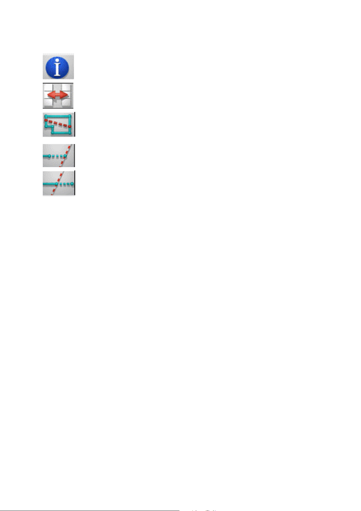
! Click on the ACTIONS menu or press function key F5.
! Import the unprepared DXF file (CAD """").
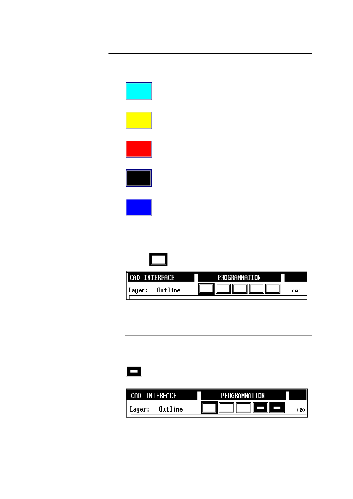
! The following window appears, allowing you to navigate in the
different directories of your system.
! Select the outline and move it to the Outline level.
! Select the bends and move them to the Bends level.
! If other indications, such as angle values, tools, material etc. are
available, and provided that they are comply with the CYCAD
prescriptions, you can also move them to the corresponding levels.
! If necessary, simplify the outline of the product in the Outline level.
! Convert the file into a PC1200 product (PRODUCT ####).
! In the PC1200 program, you can, if necessary, add missing
information such as material, tools, tool position, etc.. Then you test
the feasibility of the product as you would do with any other product
created directly with PC1200.
USING CYCAD PAGE 25
Page 30

MPORTING A
I
CAD F
In this section you find a step-by-step description of the import procedure for
an "unprepared" CAD file. For this example, the file named EX_ORI.DXF
contained in the disquette will be used. Open this file with your CAD system
to see the original DXF file.
You will notice that this file does not have any specific level, nor any
particular text corresponding to CYCAD standards. However, it contains the
bending lines with the values of their angles and - this is the only CYCADspecific item - three small oblique lines across the bending line of the upper
part of the product, indicating that this will be a forced bend (see further on in
this manual).
! Configurate the peripherals and the PREFERENCES page of
CYCAD as described in the section called Setting Parameters for
CYCAD / PC1200 Option, page 17.
! Import the EX_ORI.DXF file by clicking on the CAD """" function
key, or by pressing the CAD """" function key. (See also: Limitations,
page 15).
ILE
Then click on the EX_ORI.DXF file.
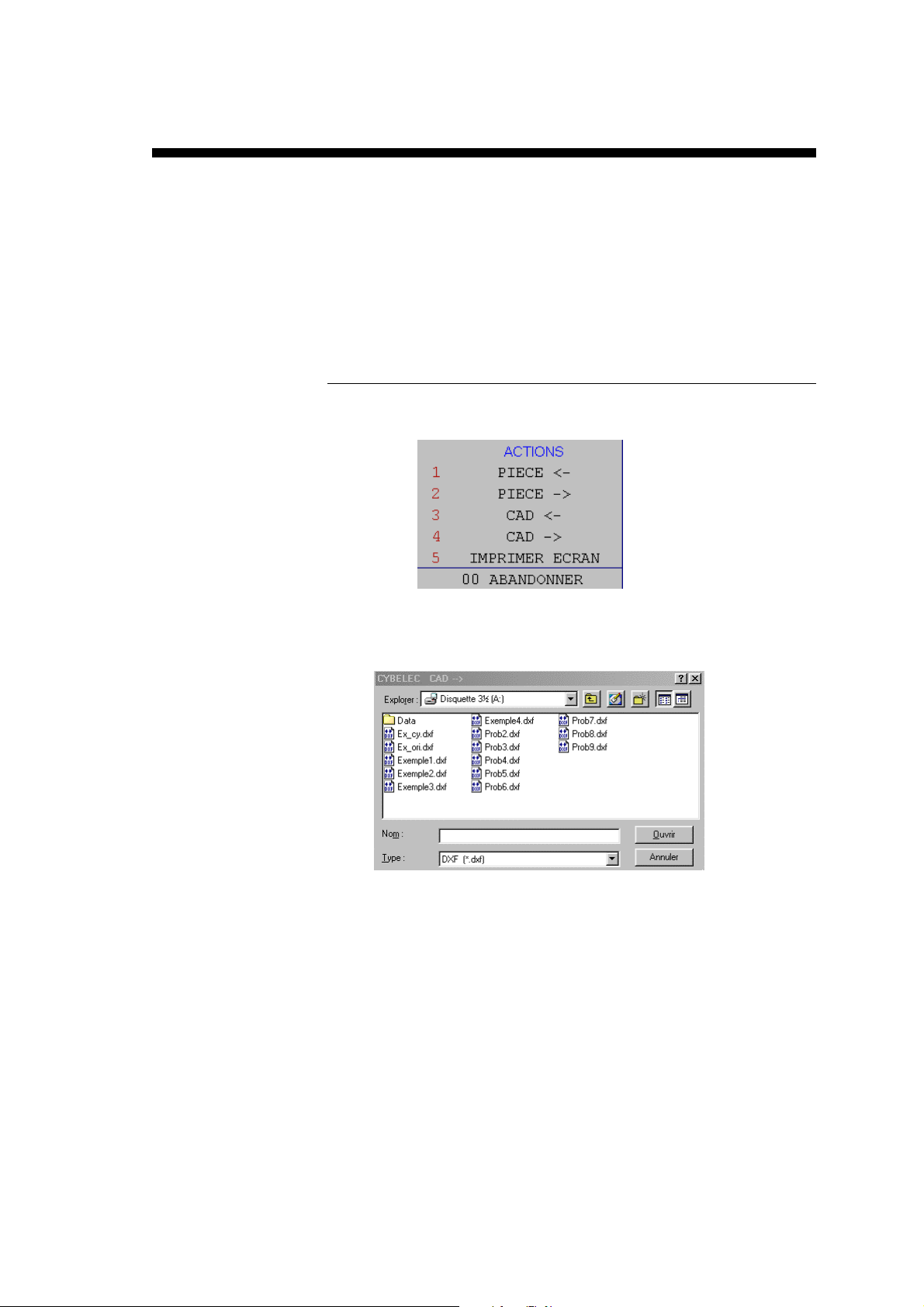
! Confirm and the drawing shown hereunder appears.
Since no other level has been defined, all elements are located in the
All other levels. This is indicated by the fact that all lines are blue.
It can be seen that in this drawing, only the upper right portion can be
used by PC1200. This is the flat layout of the product.
PAGE 26 PC 1200 / CYCAD
Page 31
! Zoom into the relevant portion.
! Activate the Select polyline icon
the outline in order to select it.
! Activate the Outline level.
Then click onto the Transfer
cyan color.
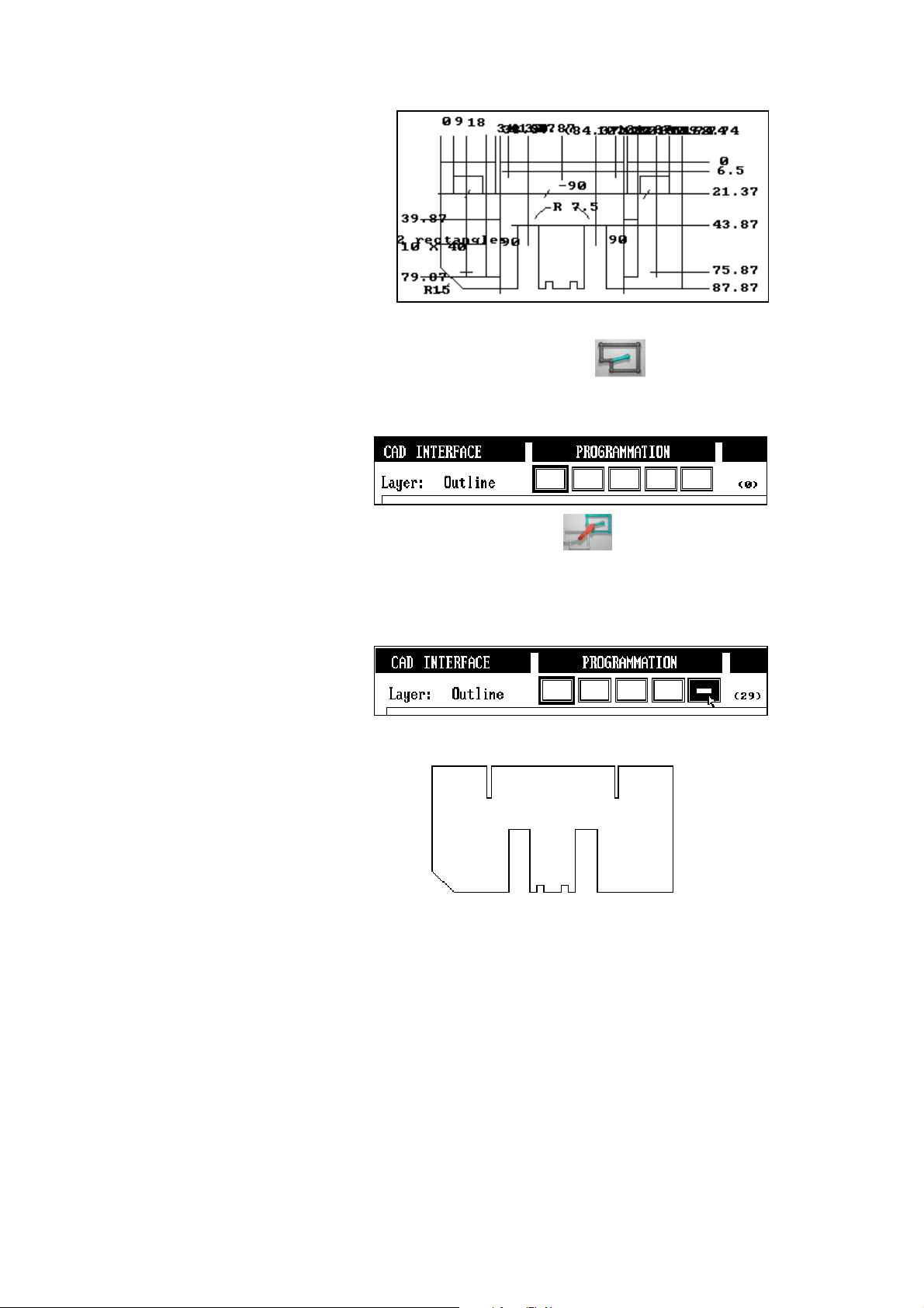
! To see the contents only of the Outline level, mask the All others
level. It is not necessary to mask other levels because, for the time
being, they do not contain any elements.
The result in the CYCAD window then looks like this:
an click onto a segment of
icon, and the outline changes to
At this stage, if no other indication is available, it is possible to
transfer this outline into the PC1200 software by clicking the
PRODUCT #### function key. It will, of course, be necessary to add all
missing information such as the material, the bends with their values,
the tools and their position etc.
! If other information is available, display once again the whole drawing
by clicking inside the blue rectangle.
In this example, the bending lines have been specified, as well as the
angle values. Activate the Bends level, select the bending lines and
related texts, and transfer them into the Bends level in the same
fashion as before.
USING CYCAD PAGE 27
Page 32

For this operation, the Selection
icon, and if necessary the zoom function must be used. The
transferred elements will appear in yellow color.
This is what you should now have on your screen after having
transferred the bends with their values, and having masked the
Outline and All others levels. The three small oblique lines
designate forced bends (see CAD Drawing Conventions, page 9).
! Convert the product by clicking on the PRODUCT #### function key.
Caution: the masked levels will not be converted, i.e. if you have
masked the Bends level, the bends will not be transferred to the
current PC1200 product. If the Outline level has been masked, an
error appears in the moment of conversion.
icon and the Select Text
! In the PC1200 program, add the tools and their positions, and test the
feasibility like you would on another product.
PAGE 28 PC 1200 / CYCAD
Page 33

S
IMPLIFICATION
If the outline of the product contains a large number of small segments which
are unimportant for the bending of the product, it may be useful or necessary
(max. number of bends reached) to simplify the outline. In the example used,
the two small notches of 5 x 5 mm will be used. The distance between the two
notches is 12 mm.
! Call up the PREFERENCES window with the
! Program Simplification limit size: 13
(It is suggested that you try out other values in order to understand the
way how this functions).
! Activate and display the Outline level.
! Activate the Select window
notches.
! Click on the Simplification
Result of the operation:
icon and select the group of
icon.
icon.
USING CYCAD PAGE 29
Page 34

XPORTING A FILE IN
E
It is possible to export a product created on PC1200 in a DXF or IGES file
for use on a CAD system. It is also possible to convert a DXF file into a IGES
file, and vice-versa.
The exported file will comply with the CYCAD conventions as described in
the CAD Drawing Conventions section, page 9.
The file will be exported to the peripheral chosen in the PREFERENCES
page. In this page, you can also select the export format (DXF or IGES), and
the number of segments for each arc.
To export a product from PC1200:
! In the PC1200 program, call up the product to be exported
! In the CAD interface program, call up the current PC1200 product by
clicking on the PRODUCT " function key.
The product is now displayed in the CYCAD window.
Note: CYCAD only calls up the current product. It is thus not
necessary that the product be memorized in PC1200.
! If necessary, you may move or delete elements.
! Click on the CAD #### function key.
! Select the directory in which the file will be saved.
DXF
OR
IGES F
ORMAT
! Enter a file name and confirm.
PAGE 30 PC 1200 / CYCAD
Page 35

XAMPLE FILES
E
On the CYCAD Example files diskette several example files are available.
Take the necessary time to open them and to have a look at them in your
CAD system. This is particularly useful to understand the use of the different
levels.
The disquette also contains a number of converted products which can be
read directly with PC1200. The numbers PRODUCT 20000 (to 20055)
designate the corresponding PC1200 product numbers.
The following files can be found on the disquette:
EX_ORI.DWG
EX_ORI.DXF
EX_CY.DWG
EX_CY.DXF
EXAMPLE1.DXF
EXAMPLE2.DXF
EXAMPLE3.DXF
Drawing created on AutoCAD in native format.
File created on AutoCAD in DXF format from
the EX_ORI.DWG file. This is the example file
used in the section Importing a CAD File.
This is a copy of the EX_ORI.DWG file. It has
been modified so as to enable automatic
conversion. This means that the indications
contained in the CAD Drawing Conventions
section have been respected.
File created on AutoCAD in DXF format from
the EX_CY.DWG file. See the comments
below, and also PRODUCT 20000.
DXF file containing the example of a product
with two internal cuts.
See also PRODUCT 20001.
DXF file containing various ways of imposing
forced bends.
See The "Bends" Level, page 12, and also
PRODUCT 20002.
DXF file containing an example of internal
forced bends (See The "Bends" Level, page
12).
EXAMPLE4.DXF
PROB2.DXF to
PROB9.DXF
SUPPLMN2.WRK
SUPPLMNT.WRK
(DATA directory)
USING CYCAD PAGE 31
DXF file containing the example of a product
for which the bend order and the supports have
been determined on CAD system level. This
bend order is recognized by PC1200 (see The
"Sections" Level, page 13 ).
DXF files relating to the Problems and
solutions section (page 33).
On this disquette are also some sample DXF
files already converted.
Page 36

The EX_CY.DXF file is the same as EX_ORI.DXF, but it has been prepared
for CYCAD at CAD system level. When looking at this file with your CAD
system, or importing it into CYCAD, you can see that the outline, the bends
and the angles have been placed in the levels according to CYCAD
"standards", and that information using CYCAD keywords have also been
integrated. Because of this, the file can be converted after having been
imported directly into a PC1200 product (PRODUCT#### key) without having
to work on it by means of the CYCAD interface. It will, however, still be
necessary to add in PC1200 the missing information and to test the feasibility
of the product.
U
SE OF THE SAMPLE DISQUETTE
In order not to modify your existing environment, the disquette has also been
made in such a way that it can be read directly by PC1200. To this effect, the
disquette contains the machine parameters and tools making it possible to
visualize the converted sample products.
To read information directly on the disquette from PC1200:
! Call the WELCOME page.
! Select ACTIVE PERIPHERALS = FLOPPY.
(See also: 2D Reference Manual).
In the CAD INTERFACE page, access the DXF example files by choosing
the DXF_A peripheral.
Note: The 3.5" disquette unit must be A:
If this is not the case, you must modify the machine parameters page
PERIPHERALS accordingly.
To return back to your original configuration, program ACTIVE
PERIPHERALS in the way they were before.
Normally, the default value is INTERNAL.
PAGE 32 PC 1200 / CYCAD
Page 37

ROBLEMS AND SOLUTIONS
P
When using CYCAD, it may happen that the software does not react in the
way you are expecting. In such cases, the present section may be useful, for it
explains the most frequently problems encountered..
On the CYCAD disquette, in the PROB directory, you will find several
DXF example files which may cause problems. They are described in the
corresponding sections.
RDER OF SECTIONS
O
CYCAD converts the sections in the order of construction. The section
established first will be given the numer 1, the second the number 2 etc. If
there are numbered sections in the CAD drawing, this numbering will be
ignored.
The order of the sections influcences the bending order, because PC1200
starts with section 1.
PROB2.DXF shows a DXF file where the sections were created in the
following order: 1 horizontal, 2 vertical. However, the numbering has been
"inverted", i.e. the vertical section was given the number 1, and the horizontal
section has number 2.
If you import this example file, you will see after conversion that
(PRODUCT FLAT) section number 1 is the horizontal and section 2 the
vertical section. They do correspond to the order of construction.
The PROB3.DXF file is identical to PROB2, but the vertical section was
created first, followed by the horizontal section as a second step.
You can import this example and see the difference in the PRODUCT FLAT
page.
ENDING LINES
B
The bending lines must be continuous lines, because on certain CAD systems
a "dotted" line is considered to be a multitude of short lines.
It is indispensable that the bending lines touch the outline at both extremities,
otherwise the line will not be converted.
The PROB7.DXF file shows a product with a "dotted" bending line. It is not
possible to select the line in a single operation, and even if each element is
selected, this bending line will not be converted.
The PROB8.DXF file shows a bending line which does not touch the outline
(top). During conversion, this line is ignored and will be lost.
Solution:
The only remedy is to make the necessary changes at CAD level.
PROBLEMS AND SOLUTIONS PAGE 33
Page 38

PEN OUTLINE
O
The conventions specify that the outline of a product must be closed. CYCAD
does not signal any particular error if this point is not respected. To the eye,
an outline may seem to be closed even if it isn't. This problem will show up
after conversion in the PRODUCT FLAT or PRODUCT 3D page.
The PROB4.DXF illustrates this explanation. The outline is not closed in the
upper left corner. To see the "gap", it is necessary to zoom extensively, for
the opening is only 0.05 mm wide. See also PRODUCT 20054 on the
CYCAD Example files disquette.
The PROB6.DXF file provides another example of an unclosed outline. In the
upper right corner, the two lines are crossing each other (exaggeratedly for
this example) but they have not been declared as closing the outline.
During conversion, the system will close the outline by using the extremity of
either one of these lines, and the outline will be incorrect. In this example, a
side-effect will be that the bending line no longer touches the outline at one
extremity and will therefore not be converted (see Bending Lines).
Solutions:
1.- Open the file with a CAD system and correct it by closing the outline.
Note: The outline of the internal cuts must also be closed.
2.- Use the functions at disposal:
Create segment
Lengthen segment
Trim two crossing
segments
ROSSING BENDS
C
The conventions do not allow bends to cross each other. Sometimes, the eye
cannot distinguish that bends are crossing. The product will be converted
without any particular message being issued. The error will be found in the
PRODUCT 3D page. The product will not be displayed, and the message Crossing Bends will be shown. The product can be seen in the BEND 2D
page.
Creates a straight segment between 2 lines.
A click close to a point creates the end of the segment on this
point. The segment is created in the same level as that of the
first line.
Click on a line which becomes the support straight line.
Click on another line. This line is lengthened, so that it cuts
the support straight line.
Click on a segment which becomes the support. Click on the
segment which crosses. The selected part of the 2
is eliminated up to the intersection with the support segment.
nd
segment
The PROB5.DXF file illustrates an example with crossing bends. The upper
horizontal bend is too low by a value of 0.01 mm. See also
PRODUCT 20055 on the CYCAD Example files disquette.
PAGE 34 PC 1200 / CYCAD
Page 39

Solution:
It is recommended to correct the problem at its source. However, since the
product can be displayed in 2D, this product can be worked on, but only in
2D. Depending on the value of the error, it will be necessary to correct the
backgauge axis.
UPERPOSED LINES
S
It may happen that you cannot select a line, or that only part of a line is being
selected.
Sometimes, during construction of a product, some construction lines remain
in the file. They are "hidden" but they may cause you some surprises when
selecting or converting items.
The PROB9.DXF file gives a small example of the phenomenon you might
encounter.
On the outline, two supplementary lines have been superimposed.
One is located on the vertical left line, the other one on the upper horizontal
line. The vertical line has the same length as the line it covers, the horizontal
one is shorter.
! Call the PROD9.DXF file into the CAD INTERFACE page.
! Activate the
to be impossible to select it.
! Now try to do the same with the upper horizontal line. You will see
immediately that it is shorter.
Solution:
Remember that one click activates the selected object, and that the subsequent
click de-activates it. The reaction can be different depending on the fact
whether the supplementary line is situated on top of or underneath the line of
the drawing.
In the case of the vertical line, select the
the vertical line. Even though it is of blue color and does not seem to be
selected, click the eraser
Proceed in the same way with the horizontal line.
Maybe you are not sure whether you have chosen the right line. In this case,
instead of erasing to line, you just transfer it into the Auxiliary level. Then
you mask it and check the situation.
icon and try to select the left vertical line. It seems
icon and click once only on
to remove the line.
PROBLEMS AND SOLUTIONS PAGE 35
Page 40

OT RECOGNIZED LEVEL
N
If, after having read a CAD file, the elements are not "placed" automatically
in the correct levels, and if the indications CYCAD : OUTLINE or
CYCAD : BENDS (or other similar information) are visible, check the
following points:
!!!! Outline level
- Only the outline and possible reserved keywords may be seen in
this level.
- The text CYCAD : OUTLINE must be written on one single line.
- The text CYCAD : OUTLINE must be written in upper case letters.
- The double point must be preceded and followed by one space.
- The syntax of the reserved keywords must be imperatively
respected (see the corresponding section).
- Make sure you use the decimal point and not the comma.
- The keywords must be placed one on top of the other.
- Make sure the outline is completely closed.
! Bends level
- This level may only contain bending lines and possible reserved
keywords.
- The text CYCAD : BENDS must be written on one single line.
- The text CYCAD : BENDS must be written in upper case letters.
- The double point must be preceded and followed by one space.
- The syntax of the reserved keywords must be imperatively
respected (see the corresponding section).
- In this level, there must not be any space before or after the equal
sign.
- Make sure you use the decimal point and not the comma.
- Place the value angles (and the keywords) in a univocal way near
the related bending line.
! Sections level
- Same remarks (see corresponding section).
Hint In any event, if you have doubts about the syntax, you can create a product
with the PC1200 software and export in in DXF or IGES format so as to
examine it with your CAD system.
OT CONVERTED ELEMENTS
N
It may happen that some elements are not converted. In this case, please make
sure that:
! All levels are visible (not masked) during conversion.
See Masking a level, page 23.
! The element is really located in one ot the 3 levels Outline, Bends
or Sections.
! Both ends of the bending lines really touch the outline (see Bending
Lines earlier in this section). If necessary, check both extremities with
a strong zoom enlargement.
PAGE 36 PC 1200 / CYCAD
Page 41

CAD INTERFACE P
If the CAD INTERFACE page doesn't appear in the main menu:
! Verify that the protection key contains really the option 2. See Setting
Parameters for CYCAD / PC1200 Option, page 17.
! Verify that the option CAD INTERFACE Page in the OPTIONS
page of the machine parameters has been activated. See Setting
Parameters for CYCAD / PC1200 Option, page 17.
! This page is available only in the PC1200 software, but not in the
numerical control.
AGE NOT AVAILABLE
PROBLEMS AND SOLUTIONS PAGE 37
Page 42

This page has been left blank intentionally.
PAGE 38 PC 1200 / CYCAD
Page 43

NDEX
I
- A -
Activate
levels 23
examples 31
- E -
Example files 9
Angle
see Bends 13
Angles
external values 19
internal values 19
Arcs 10
- B -
Bending lines 33
Bending orders 14
Bends 12
angle values 13
forced 12
internal 12
max. number 12
max. number 15
order .... 14
simple 12
supports 14
- C -
CAD Interface Page not visible 37
Complementary Information 10
Configuration
activate CYCAD 17
of CYCAD 17
of peripherals 17
Examples 5, 31
Complementary Information in a level 10
internal cut-outs 10
Exporting files 30
- F -
Files
conventions 9
description of examples 31
DXF 6
examples 9, 31
existing CAD 6
IGS 6
import 26
max. Number in a directory 15
prepared 6
read in... 18
save in.... 18
untreated 6
untreated 9
- I -
Icons
définitions 21
Illegal Configuration 17
Import
file 26
Internal cut-outs 10
Conventions 9
Conversion
problems 33
- D -
Définitions
icons 21
Difficulties 33
Discontinued lines 33
Diskette
examples 5
Disquette
INDEX PAGE 39
- L -
Layers 9
Levels 9
active 23
Auxiliary 23
Bends 12
Bends 23, 28
Complementary Information 10
masking 23
Outline 10
Outline 23
Sections 13
Sections 23
Page 44

Limitations 15
Lines
not selected 35
superposed 35
- M -
Mask
levels 23
Menu
CAD Interface not appearing 37
CAD Interface not appearing 17
conversion 28
conversion 34
elements not being converted 36
elements not converted 28
level not recognized 36
line cannot be selected 35
order of sections 33
Outline not closed 34
Superposed lines 35
Protection key 17
- S -
Messages
Illegal Configuration 17
- O -
Order of sections 33
Outline 10
not closed 34
simplification 19, 29
- P -
Plans
Outline 27
Problem
elements not converted 23
Problems 33
bending lines 33
CAD Interface choice not visible 17, 37
Sections 13
max. number 15
Segments
max. number 15
number in a given level 23
Simplification
of outline 19
Simplification of outline 29
Supports 14
- T -
Text style 9
- U -
Utilization
of the sample disquette 32
PAGE 40 PC 1200 / CYCAD
 Loading...