

Page 1
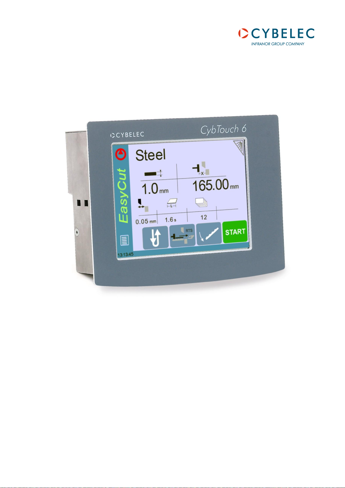
CybTouch 6 G-W
Shears
Machine Parameters Manual V.2.0
Page 2

Page left blank intentionally
Page 3

v2.0 Nov.12
TABLE OF CONTENTS
INTRODUCTION ..................................................................................................................................... 6
P01 MACHINE CONFIGURATION ......................................................................................................... 7
Menu Button 7
Toggle Pages Button 7
P01.01 Machine Type 7
P01.02 Start Pump Button 8
P01.03 Automatic Cut 8
P01.04 Quantity 8
P01.05 Material 9
P01.06 Blade Gap 9
P01.07 Second Blade Gap 9
P01.08 Axis 10
P02 MACHINE CONFIGURATION 2 ...................................................................................................... 11
P02.01 Sheet Support 11
P02.02 Return to Sender (RTS) 12
P03 MACHINE CONFIGURATION 3 ...................................................................................................... 13
P03.01 Auxilary Function 13
P03.02 Eco Mode 13
P03.03 Store/Delete Programs in Level 0 14
P03.04 HMI Locked in Level 0 14
P03.05 Toggle Pages 14
P03.06 Show Cycle Steps 14
P03.07 Retraction 15
P03.08 Analog Pressure 15
P03.09 Cutting Length Sensor 15
P04 MACHINE SETTINGS ..................................................................................................................... 16
Machine Settings Wizard 16
P04.01 Max Programmable Cutting Length 16
P04.02 Time Before Axis Start at BDC 16
P04.03 Default Time for Max Cutting Length 17
P04.04 Time to Close Hold-Downs 17
P04.05 Time to Close Hold-Downs if not TDC max 17
P04.06 Timing Valves 18
P04.07 AutoCut Minimum Waiting Time at TDC 18
P05 PREFERENCES .............................................................................................................................. 19
P05.01 Axes Start at 19
P05.02 Sheet Offset 19
PM_CybTouch6_ Shears_v2.0.doc page 3 of 55
Page 4

v2.0 Nov.12
P05.03 Angle Control at TDC Max 19
P05.04 Square Signal Low/High 19
P06 AXIS SETTINGS -X- ........................................................................................................................ 20
P06.00 Display Resolution 20
P06.01 Axis Type 20
P06.02 Closed Loop 20
P06.03 Encoder resolution 21
P06.04 Position Speed 21
P06.05 Position Tolerance 21
P06.06 One-Way Positioning 21
Advanced button 22
Axis Settings -X- Wizard 22
P06B ADVANCED AXIS REGULATOR X ............................................................................................. 25
P06b.01 Change Counting Direction 25
P06b.02 Manual Speed 25
P06b.03 Acceleration 25
P06b.04 Invert voltage & Speed at 10V 25
P06b.05 Closed Loop Frequency 25
P06b.06 Integrator factor 26
P06b.07 Offset Voltage 26
P06b.08 Supervisor Error 26
P06b.09 Supervisor Speed Level 26
P06b.10 Control Time Out 27
07 INDEXATION AXIS -X- ...................................................................................................................... 28
Indexation Axis -X- Wizard 28
P07.01 Index Type 29
P07.02 Index Zone in Reverse Logic 29
P07.03 Start Indexation in Negative Direction 29
P07.04 Indexation Speed 29
P07.05 Index Position 29
P07.06 Minimum Limit 29
P07.07 Maximum Limit 30
P07.10 Parking 30
P07.11 Parking Tolerance 30
08 AXIS FUNCTIONS -X- ....................................................................................................................... 31
P08.01 Blade Gap Factor 32
P08.02 Speed with input “Speed reduction” 32
P09 DIGITAL INPUT CONFIGURATION ............................................................................................... 33
P10 DIGITAL OUTPUT CONFIGURATION ........................................................................................... 35
P11 ANALOG I/O CONFIGURATION .................................................................................................... 37
PM_CybTouch6_ Shears_v2.0.doc page 4 of 55
Page 5

v2.0 Nov.12
P12 BLADE GAP .................................................................................................................................... 38
Blade Gap Wizard 38
P12.01 Inverted AD Input 39
P12.02 Tolerance 39
P12.03 Advanced Stop 39
P12.04 Overrun Distance 39
P12.05 SP/SN Time 39
P13 ANGLE & CUTTING LENGTH ........................................................................................................ 40
Angle & Cutting Length Wizard 40
P14 ANGLE AND CUTTING LENGTH 2 ................................................................................................ 41
P14.01 Inverted Input 41
P14.02 Resolution 41
P14.03 Minimum Limit 41
P 14.04 Distance Max TDC – Mechanical Stop 41
P14.05 TDC Time Before Angle Control 41
P14.06 Cutting Angle Tolerance 42
P14.07 Stop if Angle Sensor Max 42
P14.08 Advanced stop, angle down/up 42
P14.09 Advanced stop, cut down/up 42
P15 PRESSURE ..................................................................................................................................... 43
Pressure Wizard 43
P15.02 Minimum Pressure Beam Down 43
P15.03 Beam Up 44
P15.04 Final Approach Up (min pressure) 44
P15.05 Ramp / Final Approach Up 44
P15.06 Final Approach Speed Up 44
P15.07 Final Approach Gain 44
P15.08 Cutting Angle 44
P15.09 Blade Gap 44
P15.10 Ramp Cutting Pressure 44
CHANGING ACCESS LEVEL SECURITY PASSWORDS: ................................................................... 45
Default passwords 45
Changing passwords 45
CREATING BACKUPS AND RESTORING DATA ................................................................................. 47
Creating an Internal Backup of Machine Parameters 47
Restoring Creating an Internal Backup of Machine Parameters 47
ERROR AND WARNING MESSAGES IN CYBTOUCH 6 FOR SHEARS ............................................. 48
APPENDIX 1 – USING REMOTE CONTROL ........................................................................................ 54
Wiring Recommendation for Remote Control 55
PM_CybTouch6_ Shears_v2.0.doc page 5 of 55
Page 6

v2.0 Nov.12
INTRODUCTION
This manual is specifically written for qualified technicians.
Information contained herein will serve as a guide for all technicians setting up shear
machines with the Cybelec CybTouch 6 numerical control.
The following documents may also be useful to a technician for setting up and testing
a shear machine with the CybTouch 6:
CybTouch 6 for shears user manual:
CybTouch6_Shear_Usermanual_EN_vx.x.pdf
CybTouch 6 for shears technical manual:
CybTouch_6_G_1612io_Technical_manual_vx.x.pdf OR
CybTouch_6_W_88io_Technical_manual_vx.x.pdf
The present manual will describe all machine parameters of the CybTouch.
Please note that modifications to the machine parameters may imply additional inputs
or outputs to be configured (also done in the machine parameters), and will have a
direct effect on the HMI. Functions and/or buttons will be deactivated/hidden/made
available depending on the machine configuration.
This manual describes all features of CybTouch 6 X or G with software
version 2.0.0.
PM_CybTouch6_ Shears_v2.0.doc page 6 of 55
Page 7
v2.0 Nov.12
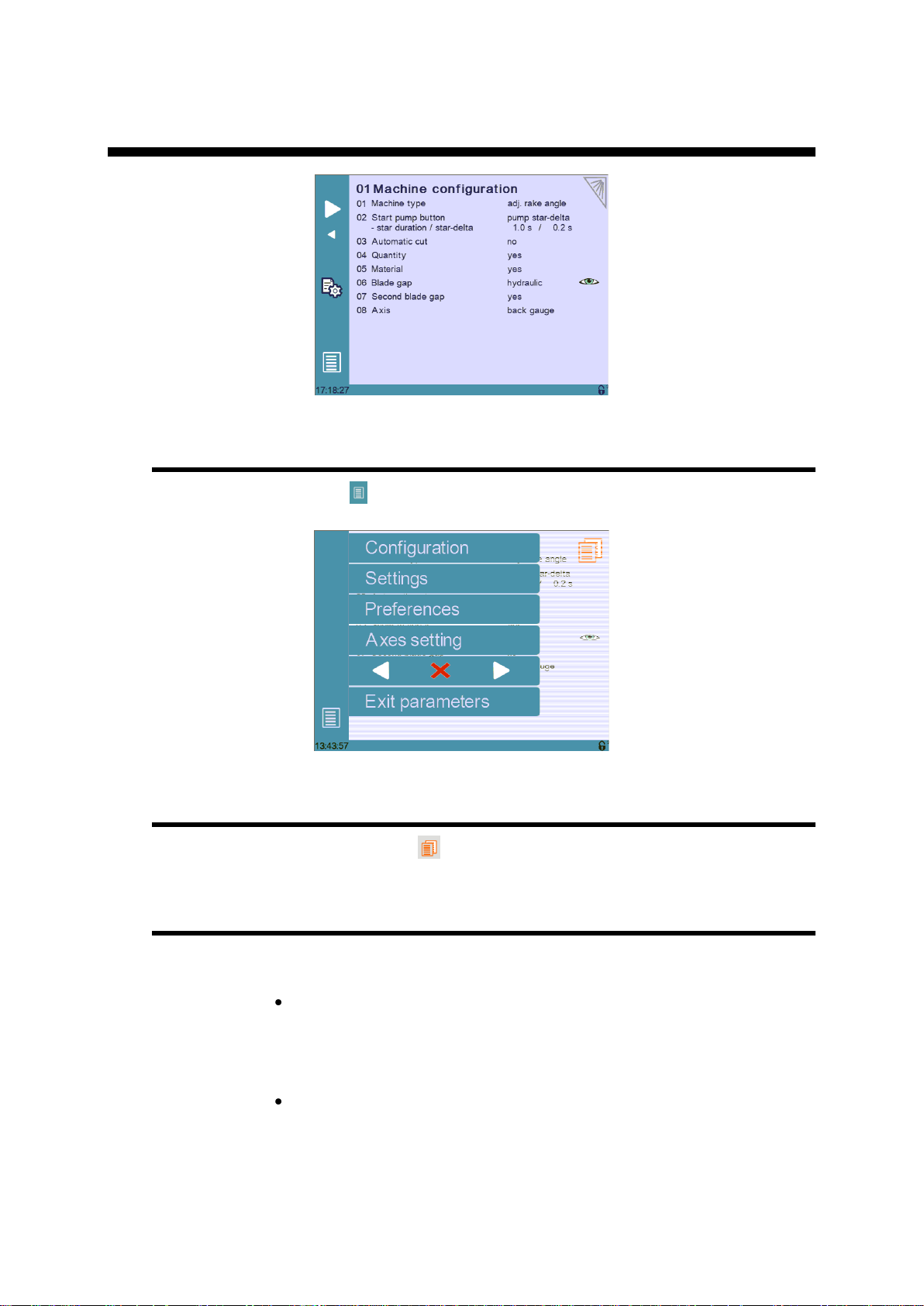
P01 MACHINE CONFIGURATION
Menu Button
The Menu button allows you to exit the P01 Machine Configuration page or to
scroll through the other machine parameters pages:
Toggle Pages Button
The Toggle pages button
P01.01 Machine Type
Touch the Machine type field to choose the type of machine used with the
CybTouch:
Adjustable rake angle: Select this mode if your machine has a rake
angle managed by the CybTouch. Angle and cutting length are managed
by a sensor (potentiometer or linear encoder).
Selecting this option will give you access to dedicated machine
parameters for controlling this type of shears.
Swing: Select this mode if your machine has a fixed angle. The cutting
length is managed by a timer.
is described in section P03.05 Toggle Pages.
PM_CybTouch6_ Shears_v2.0.doc page 7 of 55
Page 8
v2.0 Nov.12
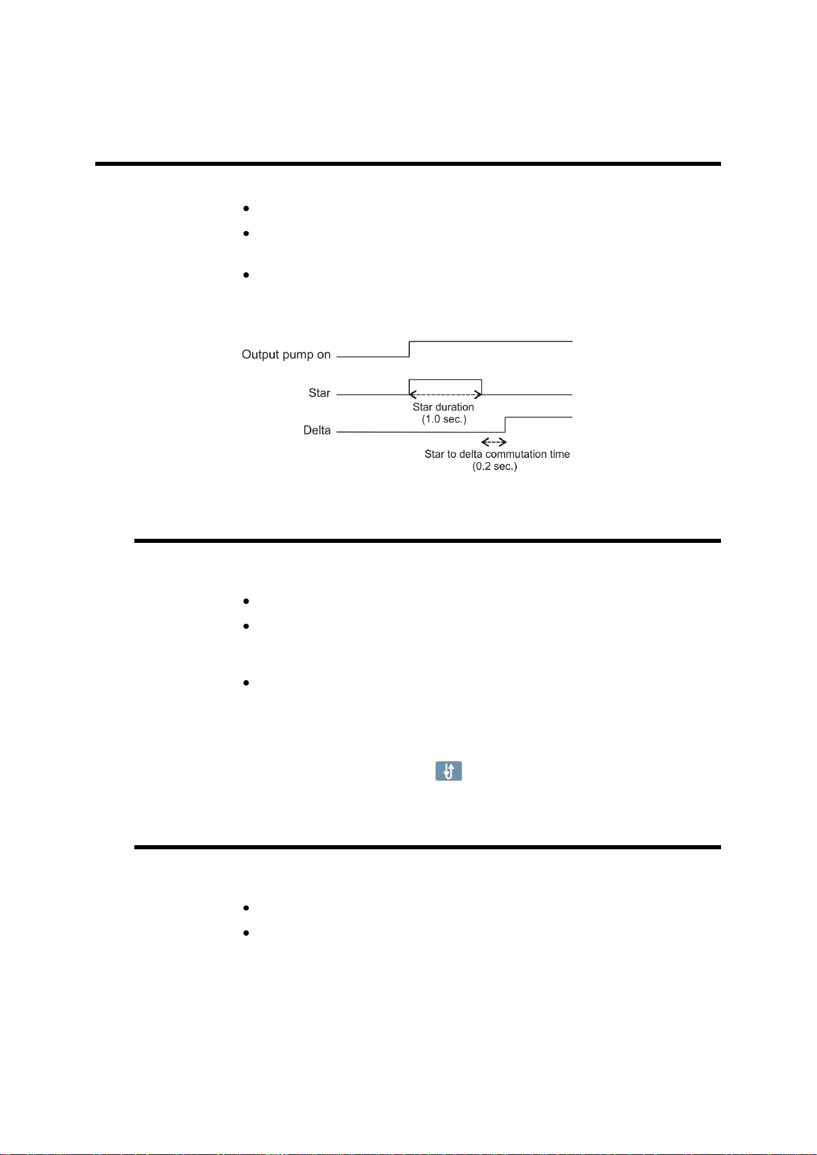
P01.02 Start Pump Button
Touch the Start Pump field to select:
No = Start Pump: start pump button is not available on screen.
Yes = Start Pump start pump button is available on screen.
1 output (Pump_on) is dedicated to this.
Pump star delta start pump button is available on screen.
3 outputs are dedicated to the star delta pump start.
1.0s = star duration.
0.2s = star to delta commutation time.
P01.03 Automatic Cut
The Automatic cut function is only available in EasyCut mode, and can be
configured as follows:
No: The Automatic cut function is disabled.
Yes, auto stop: The Automatic cut function is enabled but will be
deactivated when the operator releases the foot pedal. The operator then
has to press the Automatic cut button again to work in AutoCut mode.
Yes, no auto stop: The Automatic cut function is enabled and will
remain enabled, even after releasing the pedal. Usually, if this feature is
configured a key switch is wired to the machine to allow (or not) the
Automatic cut function.
Note: The Automatic cut input must be activated to enable the
Automatic cut icon ( ) on the screen.
P01.04 Quantity
When enabled, the Show quantity function allows the operator to enter a number
of times a program can be repeated (number of pieces to be produced).
No: The quantity counter is not displayed.
Yes: The quantity counter is displayed; the operator can enter a number
of pieces to be produced.
PM_CybTouch6_ Shears_v2.0.doc page 8 of 55
Page 9

v2.0 Nov.12
P01.05 Material
When enabled, the Show material function will display the material type used and
allow the operator to change the material type:
Yes: Material selection is displayed; the operator can select the material
type.
No: Material selection is not displayed. Blade gap is also not visible
- Minimum display Yes/No
When set to Yes, the working pages of the interface are simplified
(less icons) so that the CybTouch can be used as a positioner
control.
P01.06 Blade Gap
The blade gap is adjusted according to the selected material and thickness. These
values are set in the Material page by the machine manufacturer. Usually the blade
gap is not modified by the operator and is only shown to the operator.
Note: Blade gap feedback can only be provided by a potentiometer.
No: No blade gap management; blade gap icon and value are not
displayed and cannot be configured in machine parameters.
Show only: Blade gap is not managed by the CybTouch (manual blade
gap) but the blade gap values must be entered in Material page.
When the P01.05 Material is set to Show only, icon and value are
displayed for reference only to the operator (P12 Blade gap page is
hidden).
Electric or Hydraulic: choose the type of blade gap (electric motor or
hydraulic cylinder). The icon and value are displayed and can be
configured in machine parameters (P12 Blade gap page).
Note: When Hydraulic is selected, Pressure output must be
configured.
: Blade gap value is visible on work pages.
: Blade gap value is not visible on work pages.
Note: If the operator needs to change the blade gap, it must be set as
visible and the programmable tolerances must be set in the Material
pages. See Materials section in CybTouch 6 user guide for more
details.
P01.07 Second Blade Gap
A second blade gap can be configured. See P12 Blade gap page for calibration.
No: Only 1 blade gap actuator.
Yes: If a second blade gap is needed.
Note: Blade gap feedback can only be provided by a potentiometer.
PM_CybTouch6_ Shears_v2.0.doc page 9 of 55
Page 10

v2.0 Nov.12
P01.08 Axis
Back gauge: The back gauge is configured and can be used.
Front gauge: The front gauge is configured and can be used.
P01.09 Clamp parameter becomes available.
None: The back gauge is disabled (screen and management). This
feature is commonly used at startup of the machine.
PM_CybTouch6_ Shears_v2.0.doc page 10 of 55
Page 11

v2.0 Nov.12
P02 MACHINE CONFIGURATION 2
P02.01 Sheet Support
The sheet support cycle must be managed by the electrical box.
The sheet support function activates 1 output for Sheet support 2 (with
2 positions) or 2 outputs for Sheet support 3 (with 3 positions).
The sheet support can be configured as follows:
No: No sheet support.
Sheet support 2 pos: Sheet support with 2 positions (1 output).
Sheet support 3 pos: Sheet support with 3 positions (2 outputs).
Disable support in zone: E.g. 0.0 – 300.0 mm values are
entered: for a part less than 300 mm in length, sheet support isn’t used.
Note: Once configured, the sheet support button is available in the
work pages for the operator to select.
PM_CybTouch6_ Shears_v2.0.doc page 11 of 55
Page 12

v2.0 Nov.12
P02.02 Return to Sender (RTS)
Sheet support must be configured to activate the RTS function. The RTS function can
be configured as follows:
No: RTS is not configured.
o Warning: RTS is configured and operator will see a warning popup
if max weight is exceeded. Operator can acknowledge the popup
and continue by pressing the foot pedal.
o Not allowed: RTS not available if max weight, min X dist, or
max X distance is exceeded.
RTS allowed in park position: RTS can be allowed or not when
the gauge is in parking position.
Retraction distance: RTS mode back gauge retraction distance is
usually greater than normal retraction.
Return speed: Speed at which the cut piece is pushed back to the
sender by the back gauge. The return is triggered by touching the RTS
button on the screen or using the RTS move input.
Min X dist: Minimum length of the part for which the RTS will be used,
depending on the choice made above.
Max X dist: Maximum length of the part for which the RTS will be used,
depending on the choice made above.
Max weight: Maximum weight of the part for using RTS function,
depending on the choice made above.
PM_CybTouch6_ Shears_v2.0.doc page 12 of 55
Page 13

v2.0 Nov.12
P03 MACHINE CONFIGURATION 3
P03.01 Auxilary Function
Several preset auxiliary functions can be configured: light, scrap, and ejector. And one
or two freely configurable auxiliary functions can be added: F1 or F1+F2.
None: No auxiliary function configured.
Light: Light is configured.
F1: 1 auxiliary function is configured and called F1.
F1+F2: 2 auxiliary functions are configured, called F1 and F2, and can
be used separately or at the same time.
Scrap: The scrap function is configured. The scrap feature is a
compartment that opens to receive scrap cuts.
Ejector: The ejector function is configured. The ejector function is used
usually with front gauge to push the remaining metal backwards.
When auxiliary functions are configured, the below parameter determines if they are to
be applied to the whole machine (on-off on operator use), saved in the complete
program for a specific part, or saved in a sequence in a part.
mode: machine/part/sequence.
P03.02 Eco Mode
The Eco mode parameter defines after how much time of operator or machine
inactivity the CybTouch will switch to economical mode.
When switching into Eco mode the Pump on output is turned off and the screen
becomes darker.
Current value is usually 5-15 min.
Setting the Eco Mode to 0.0 min deactivates Eco mode.
Note: If the Start Pump button is not configured on the screen, but
wired conventionally, the Eco mode off output can be used to
switch off the pump after the Eco mode time is reached. Please refer
to basic electrical diagrams in the CybTouch 6 technical manual.
PM_CybTouch6_ Shears_v2.0.doc page 13 of 55
Page 14

v2.0 Nov.12
P03.03 Store/Delete Programs in Level 0
Here you can choose whether or not operators with access level 0 can be authorized
to store or delete programs in the CybTouch.
P03.04 HMI Locked in Level 0
The Human Machine Interface can be locked in level 0. This is commonly used when
machines are left unattended on exhibitions to prevent visitors from changing
programs.
When set to Yes, the operator will need a code to access programming (level 2).
The HMI will be automatically locked every time:
The CybTouch is switched off.
The CybTouch switches to Eco mode.
The HMI can be locked manually by opening the menu and pressing the icon.
The unlocking code is “55". See section Changing Access Level Security Passwords.
Another option: EasyOK, means that the CybTouch is locked in the EasyCut page.
This option is to make the machine very simple.
P03.05 Toggle Pages
If activated, the toggle button allows you to switch directly from any parameter
page "back" to the last working page visited before accessing the parameters.
Once you are in the working pages, touching allows you to return to the last
accessed parameter page.
This functionality is very useful for technicians during the machine set-up.
Its vivid orange color just informs the technician that this toggle page mode is active
and acts as a reminder to deactivate this functionality before machine delivery.
The Toggle pages button will disappear automatically from operator pages (Toggle
page parameter set to no) after 24 hours of inactivity.
P03.06 Show Cycle Steps
Cycle steps messages at the top of the screen can be displayed or not by activating or
deactivating the Show Cycle Steps parameter.
Ex: .
By default this parameter is set to Yes. The operator immediately knows in which
phase the machine currently is. This feature and the Machine Status pages are very
helpful during the first service calls between the operator and the service technician.
PM_CybTouch6_ Shears_v2.0.doc page 14 of 55
Page 15

v2.0 Nov.12
P03.07 Retraction
Retraction of the back gauge can be set as follow:
No: The backgauge will not retract.
Always: The backgauge will always retract.
Selectable: The backgauge will retract or not, this is defined by
operator.
Retraction is only possible if AutoCut function is active.
Retraction distance: Backgauge retraction distance
Mandatory for thickness over: Retraction is mandatory if
material is thicker than this parameter value.
P03.08 Analog Pressure
Analog pressure can be configured if a proportional pressure valve is used for the
system pressure of the machine. Output manages ramps and pressure levels
depending on programmed material.
When P03.09 Analog Pressure is set to Yes, P15 Pressure becomes available
in machine parameters.
P03.09 Cutting Length Sensor
CybTouch 6 G allows the choice between a linear encoder or a potentiometer for
angle and cutting length functions.
If 2 blade gaps are used, the angle and cutting length sensor must be an
encoder.
The sensor (potentiometer/linear encoder) must be positioned as far as possible to the
right of the machine in order to obtain maximum precision.
Encoder index must be positioned near to BDC (approx. 10 - 20 mm), before the
blades cross.
PM_CybTouch6_ Shears_v2.0.doc page 15 of 55
Page 16
v2.0 Nov.12
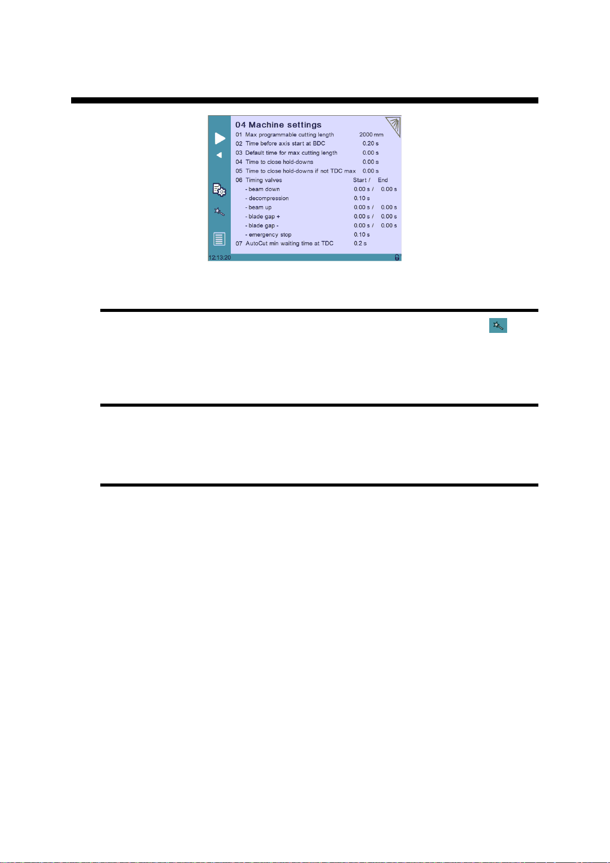
P04 MACHINE SETTINGS
Machine Settings Wizard
When a swing shear machine is used, a Wizard is available by touching the
button. This allows you to measure the default time for the maximum cutting length.
See section P04.04 Default Time for Max Cutting Length for more details.
P04.01 Max Programmable Cutting Length
This parameter is only available with swing shear machines. It is the maximum cutting
length, depending on the machine dimensions.
P04.02 Time Before Axis Start at BDC
After the beam begins to move up from BDC, this is an extra time that can be set
before axes (sheet support and back gauge begin to move. This parameter is only
active if P05.01 Axes Start At is set to BDC.
PM_CybTouch6_ Shears_v2.0.doc page 16 of 55
Page 17
v2.0 Nov.12
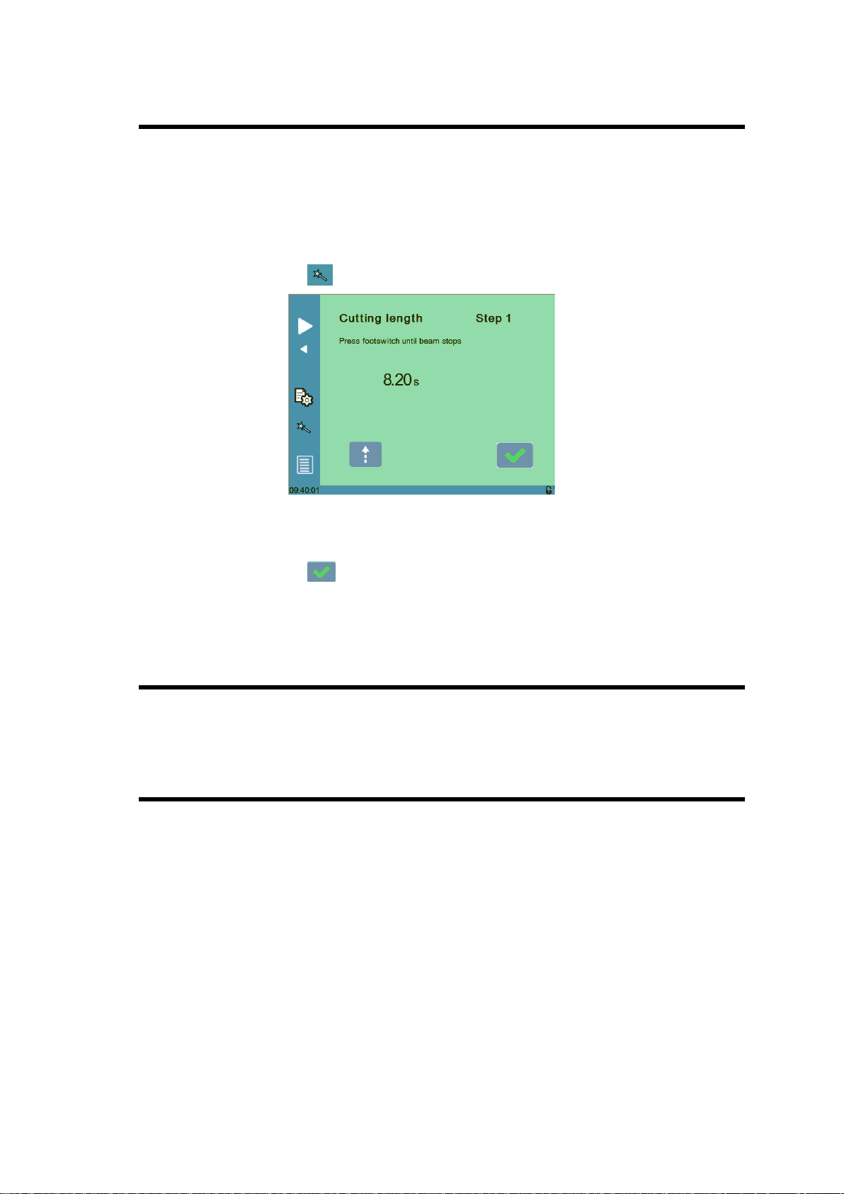
P04.03 Default Time for Max Cutting Length
This is the default time it takes to cut a piece with the previously set maximum cutting
length in P01 Maximum Cutting Length.
This is the value set by default when working in the EasyCut and Program page.
This is also the maximum time the operator can program.
This parameter is only available with swing shear machines.
This time can easily be measured using the Wizard:
1. Touch the button, the below Wizard is displayed:
2. Press the foot pedal to lower the beam, the time it takes for the beam to go from
TDC position to BDC is measured (here 8.20 seconds).
3. Touch the button to exit the Wizard and return to the machine parameters
page.
4. The programmed cutting length value is now set.
P04.04 Time to Close Hold-Downs
This parameter determines the time before the output Time hold dn closed (for closing
the holdowns) is activated after the beam starts to descend from TDC max.
P04.05 Time to Close Hold-Downs if not TDC max
This parameter determines the time before the output Time hold dn closed (for closing
the holdowns) is activated after the beam starts to descend from a point below TDC
max, upon pressing foot pedal.
PM_CybTouch6_ Shears_v2.0.doc page 17 of 55
Page 18

v2.0 Nov.12
*Or beam up, blade gap +, blade gap -
P04.06 Timing Valves
This parameter is used to manage system pressure for hydraulic systems in the
machine by timing the opening and closing of valves according to the system
pressure:
E.g.: Beam down 0.20s / 0.30s
P04.07 AutoCut Minimum Waiting Time at TDC
This parameter determines the minimum time that the blade must stay at TDC
between cuts in automatic cut mode.
This is to ensure a smooth and less brutal change of direction/pressure in the system.
PM_CybTouch6_ Shears_v2.0.doc page 18 of 55
Page 19

v2.0 Nov.12
P05 PREFERENCES
P05.01 Axes Start at
The axes (back gauge) can be configured to start positioning at different moments,
depending on the position of the beam:
BDC if X SP:
o If the axes movement will be in positive direction, axes (back
gauge) will start once the beam reaches BDC.
o If the axes movement will be in negative direction, axes (back
gauge) will wait and start once the beam reaches TDC.
BDC: Back gauge starts moving when beam reaches BDC.
TDC: Back gauge starts moving when beam reaches TDC.
P05.02 Sheet Offset
Only available with adjustable rake angle machines.
If configured, allows the operator to set a series of cuts to be made in the center of the
machine without the beam having to return to TDC max for each cut. This function is
only available if the machine is capable of stopping in the middle of a return of stroke.
P05.03 Angle Control at TDC Max
Only available with adjustable rake angle machines.
The CybTouch can be configured to check the blade angle at TDC Max.
It can be configured to perform this check every X number of cuts (value between 1
and 999 cuts). More frequent controls are usually used for older machines or
machines with hydraulic systems with minor leakage.
Setting this parameter to 0 disables the angle check at TDC Max.
P05.04 Square Signal Low/High
The square signal is used to carry out tests on the machine. This signal is available on
one output Square signal and must be configured to be used.
PM_CybTouch6_ Shears_v2.0.doc page 19 of 55
Page 20

v2.0 Nov.12
P06 AXIS SETTINGS -X-
P06.00 Display Resolution
This value must be entered manually before using the Wizard.
Here you must set the displayed resolution for the selected axis to 0.01 mm,
0.1 mm or 1 mm.
P06.01 Axis Type
This value must be entered manually before using the Wizard.
Depending on the drive logic, you must select either:
For DC or AC brushless motor, select Enable +/-10V.
For frequency converter with asynchronous motor, select either
If a frequency converter is used, the offset must be 0.0 V.
En/SN 0/10V, or SP/SN 0/10V according to the drive logic.:
P06.02 Closed Loop
Must be programmed manually before using the Wizard.
If you are using a frequency converter this parameter must be set to No.
PM_CybTouch6_ Shears_v2.0.doc page 20 of 55
Page 21

v2.0 Nov.12
P06.03 Encoder resolution
The encoder resolution can be programmed if it is already known
It can also easily be determined using the axis Wizard .
P06.04 Position Speed
Must be programmed manually before using the Wizard.
Here you must enter an approximate realistic positioning speed for the back gauge.
The real maximum positioning speed will then be determined by the Wizard.
P06.05 Position Tolerance
Must be programmed manually before using the Wizard.
Here you must enter the position tolerance accepted by the machine for the axis.
P06.06 One-Way Positioning
Back gauge positioning can be configured here. Various configurations are possible;
here are some examples which display how to configure this parameter:
Bi-directional positioning without final approach:
Bi-directional positioning with final approach of 5 mm at 1 mm/s:
One-way positioning with overrun of 30 mm:
PM_CybTouch6_ Shears_v2.0.doc page 21 of 55
Page 22

v2.0 Nov.12
One-way positioning with overrun of 30 mm +final approach of 5 mm
and 1 mm/s:
Advanced button
Touching the Advanced button displays the P06b Advanced Axis Regulator
page.
These parameters are automatically generated by executing the Wizard described
below. See section P06b Advanced Axis Regulator X for more details.
Axis Settings -X- Wizard
Important: Before using the Wizard, a number of parameters must be set manually,
see section P06 Axis Settings –X-.
For this example of axis setting, we will enter the below values in the 06 Axis settings
X Page:
Axis type En/SN 0/10V
Closed loop no
Time before 0.0s
Encoder resolution xxxxx p/mm
Positioning speed 60,00 mm/s (*)
One way positioning: no.
(*) Make sure this speed is at least 30 to 40 % lower than the expected final
speed.
1. Touch the Wizard button to launch a Wizard to help you set the axis.
Simply follow the instructions in the Wizard for the following:
Axis movement direction:
2. Program the voltage to a value of minus 30-50%
(30% = auto-tuning will be made with max 3V output. 50% = auto-tuning done
with 5V output)
3. Simply follow instructions in the Wizard.
4. Proceed the same for the following steps:
Axis resolution.
Axis position test.
Note: if the mechanical position is not right when you measure it,
restart the wizard.
Axis limits.
PM_CybTouch6_ Shears_v2.0.doc page 22 of 55
Page 23

v2.0 Nov.12
Axis identification:
5. Set the direction (01 Direction) in which the axis should move. The axis will
move for its identification for a certain time as defined in the next steps. Choose
the axis direction where the most distance is available for the stroke.
6. Set a test voltage (02 Voltage) for axis movement, 2 to 5 V preferably.
Start tests with a small v at the beginning in order to observe axis reaction.
7. Set the duration (03 Time) for axis movement, 2 to 4 sec preferably (but
depending on the axis speed). Start with small value. Too small value will
results one error. Increase the time if error 56 is shown (see errors on page 48).
8. Touch Start,
a. Axis starts a movement with above values, oscillates, stops, and then
returns near to the start position.
b. The Positioning OK message appears and the 10 speed at
10V value is calculated.
Note: P06.04 Positioning speed = 10 Speed at 10 V – 15%.
The P06.04 Positioning Speed can be made lower but never higher.
If an identification error [ ] occurs:
i. Err 1 = No motion detected. Should not happen if you
started the Wizard from the beginning.
ii. Err 2 = Not enough oscillations.
Increase the above identification time.
iii. Err 3= Oscillation amplitude.
Increase the above identification voltage.
In all cases, make sure that the amplifier / frequency converter doesn't
have internal ramps.
If ramps are set, turn them off (or set them to 0).
Make sure that no tests are performed by the drive at start movement.
If tests are set, turn these tests off (such as the inductance or poles
tests).
PM_CybTouch6_ Shears_v2.0.doc page 23 of 55
Page 24

v2.0 Nov.12
9. Touch to move on to Axis Tuning.
Axis tuning:
1. Choose between closed loop and open loop. Select open loop if frequency
converter is used.
2. Reduce the 04 Positioning speed if needed, never make it higher.
3. Increase or decrease manual speed depending on machine behavior.
4. Increase or decrease acceleration speed depending on machine behavior.
5. Enter a position in the field above and touch START.
6. Verify that X axis went to the right position. Repeat with different values.
Adjust 03 Acceleration to your convenience.
And if necessary set a final approach distance and or the one-way positioning
mode (in P06.06 One-way positioning).
All tests and axis adjustments can easily be made in this page.
After executing the Wizard, the backgauge is set to run in normal operating conditions.
7. Touch to move on to Axis Tuning.
Axis tuning:
1. Choose between closed loop and open loop. Keep open loop if frequency
converter is used.
2. Reduce the 04 Positioning speed if needed, never make it higher.
3. Increase or decrease manual speed depending on machine behavior.
4. Increase or decrease acceleration speed depending on machine behavior.
5. Enter a position in the field above and touch START.
6. Verify that X axis went to the right position. Repeat with different values.
Adjust 03 Acceleration to your convenience.
And if necessary set a final approach distance and or the one-way positioning
mode (in P06.06 One-way positioning).
All tests and axis adjustments can easily be made in this page.
After executing the Wizard, the backgauge is set to run in normal operating conditions.
PM_CybTouch6_ Shears_v2.0.doc page 24 of 55
Page 25

v2.0 Nov.12
P06B ADVANCED AXIS REGULATOR X
All parameters in this chapter are automatically calculated by the Wizard.
This page is accessed by touching the advanced button on P06 Axis Setting.
P06b.01 Change Counting Direction
This parameter changes the counting direction for the axis movement/positioning.
P06b.02 Manual Speed
This parameter determines the manual movement speed for the axis in mm/sec.
P06b.03 Acceleration
This parameter determines the X axis default acceleration speed.
The bigger the value is, the faster the acceleration is.
P06b.04 Invert voltage & Speed at 10V
The theoretical maximum speed of the axis with 10V applied to the drive.
This value is set by the Wizard and should be handled manually with great care, or
simply left to be calculated by the Wizard.
The sign in front of the value (+ or -) shows inversion or not.
P06b.05 Closed Loop Frequency
This parameter determines the level of proportional gain. This value is set by the
Wizard and should be handled manually with great care, or simply left to be
calculated by the Wizard.
PM_CybTouch6_ Shears_v2.0.doc page 25 of 55
Page 26

v2.0 Nov.12
P06b.06 Integrator factor
Integral gain. This value is set by the Wizard.
Can be adjusted manually to increase positioning accuracy.
P06b.07 Offset Voltage
Offset voltage, 0 - 9.999V
P06b.08 Supervisor Error
Supervisor error 0 - 999.99 mm
999.99 = no test
Usually programmed:
10 - 30 mm with frequency converter and
5-10 mm with servo-drives.
This is the max allowed distance between the calculated and the real trajectory.
If during movement the value in P06b.08 Supervisor error is exceeded, the
CybTouch stops the movement and displays FW Err 32 Trajectory following
error.
If this occurs, try to slow down the positioning speed and or acceleration, or check
that the axis has no mechanical friction spots on its stroke.
Refer to the error description chapter for additional information.
P06b.09 Supervisor Speed Level
Speed supervisor level 100%.
0 = no test.
Usually programmed:
20-30% with frequency converter and
5-10 % with servo-drives.
This is the max. allowed speed difference between the calculated and the real
speed.
If during movement speed difference exceeds the value in P06b.09 Supervisor
speed level, the CybTouch stops the movement and displays FW Err 39
Speed following error.
If this occurs, try to slow down the positioning speed and/or acceleration, or check
for friction points on the axis stroke.
Refer to the error description chapter for additional information.
PM_CybTouch6_ Shears_v2.0.doc page 26 of 55
Page 27

v2.0 Nov.12
P06b.10 Control Time Out
Control time out 9.999s
0 = no test
Usually programmed
0.4 to 0.8s with frequency converter, and
0.2 -0.4s with servo-drives.
This is the max allowed time with regulator at max voltage.
If this error appears, it means the regulator had to provide 10V for at least the
duration programmed in this parameter.
If at start and during movement, the value in P06b.10 Control time out is
exceeded, the CybTouch stops the movement and displays FW Err 33 Maximum
voltage time exceeded.
Refer to the error description chapter for additional information.
PM_CybTouch6_ Shears_v2.0.doc page 27 of 55
Page 28

v2.0 Nov.12
07 INDEXATION AXIS -X-
Most of these parameters are set during the Wizard procedure. They can be
modified manually if necessary.
This machine parameters page can display parameters for more than one axis.
Simply touch –X– or –Y– in the page title to switch from one axis to the other.
Indexation Axis -X- Wizard
Touch the indexation Wizard button to launch the axis indexation Wizard and
follow instructions. Make sure you select the type of index before launching the
Wizard.
PM_CybTouch6_ Shears_v2.0.doc page 28 of 55
Page 29

v2.0 Nov.12
P07.01 Index Type
None: No indexation.
Index and zone:
Axis enters the index zone (24V input),
Reverses direction and exits the zone, and then
The first 5V encoder index = index is taken.
Index only:
At first 5V encoder index = index is taken.
Index zone only:
Axis enters the index zone (24V input),
Reverses direction and exits the zone.
The axis indexes when leaving the index zone.
Mechanical stop:
There is no index zone switch or index.
The axis move in index speed until it is stopped mechanically at
end of the stroke.
The mechanic axis stop = index.
This indexing mode requires precise and constant mechanic stop
and a slow indexing speed.
Mechanical and index:
Same as above, but the mechanical stop acts as an indexing zone.
The axis stops on the mechanical stop (can be a rubber stop to
reduce strength on the axis)
Axis reverses direction and exits the zone.
At first 5V encoder index = index is taken.
P07.02 Index Zone in Reverse Logic
Inverts the input signal function. 24V or 0V active depending on selection.
P07.03 Start Indexation in Negative Direction
Indexation starts in positive or negative direction. This parameter is used in
conjunction with above P07.02. IndexZone in Reverse Logic.
P07.04 Indexation Speed
Defines the axis indexation speed.
P07.05 Index Position
Defines the index position. This value is set using the Wizard.
P07.06 Minimum Limit
Defines the minimum limit position. This value is set using the Wizard.
PM_CybTouch6_ Shears_v2.0.doc page 29 of 55
Page 30

v2.0 Nov.12
When the operator touches the back gauge icon, it changes
to the foldaway icon and value is hidden. The backgauge
automatically moves to its parking position.
If a foldaway system is used, enter the ramp start value and
speed on ramp value.
If no ramp, set the ramp start at smaller value than parking
position and program speed on ramp at same value as
positioning speed.
P07.07 Maximum Limit
Defines the maximum limit position. This value is set with the Wizard.
P07.10 Parking
Note: Parking position must be smaller than P07.07 Maximum limit parameter
value.
P07.11 Parking Tolerance
This parameter determines the tolerance for the gauge’s parking position.
Recommended Parking Tolerance is 10.0 to 20.0 mm.
PM_CybTouch6_ Shears_v2.0.doc page 30 of 55
Page 31

v2.0 Nov.12
08 AXIS FUNCTIONS -X-
If there are several axes, touch the axis name –X– or –Y– on top of the page to
switch from one axis to the other.
PM_CybTouch6_ Shears_v2.0.doc page 31 of 55
Page 32

v2.0 Nov.12
Blade gap
fracture width
Sample values (mm):
- blade gap = 1.00
- fracture width = 0.40
- cut length = 100.00
needed correction 0.60
P37 = 0.6
1.00
99.000.40
0.40
0.00 100.00
needed correction -0.4
P37 = - 0.4
1.00
100.000.40
0.40
0.00
100.00
needed correction - 1.00
P37 = 0.6
1.00
101.00
0.40
0.00100.00
P08.01 Blade Gap Factor
The blade gap factor is used to correct the x axis value with regards to the blade gap
value and the backgauge fixing point or if front gauge.
P08.02 Speed with input “Speed reduction”
The Speed reduction input allows you to reduce the positioning speed of the axis.
Enter here the speed when the input is active.
PM_CybTouch6_ Shears_v2.0.doc page 32 of 55
Page 33

v2.0 Nov.12
P09 DIGITAL INPUT CONFIGURATION
The inputs can be modified according to the machine requirements.
Simply touch a field and select the output to configure:
Note: Use the arrows to scroll through the available inputs.
Doubling inputs will result in error (configuration error) while leaving machine
parameters.
PM_CybTouch6_ Shears_v2.0.doc page 33 of 55
Page 34

v2.0 Nov.12
INPUT
RECEIVED SIGNAL
Safety system down
Inform the CybTouch that the safety system is
deactivated
Pedal
Down Pedal is pressed
Automatic cut
AutoCut function is enabled (external switch)
TDC max
Beam has reached the max beam position switch
(TDC = Top Dead Center)
BDC min
Beam has reached min beam position switch
(BDC = Bottom Dead Center)
X index zone
X axis is in the index zone (index zone active)
Speed reduction X
When active, X axis runs at reduced speed (P08.02)
External stop
When activated, stops all movement of the CybTouch.
Must be deactivated to let the CybTouch start again.
RTS ready
If configured, this signal inform the CybTouch that the
RTS (return to sender) system is in its final up position
and operator can use the “return” button to move the
plate back to him. If not in position, the “return” button will
not be active
RTS move
The RTS return button on the CybTouch may not be
convenient for the operator to move the plate backward to
him. On external switch may be mounted in a more
convenient place for this operation. Configure this input
and connect the external switch. Both buttons (switch and
screen) can be activated.
Beam up
Beam moving up by remote control (*1).
Blade gap 1 select
Selects blade gap1 using remote control (*1).
Blade gap 2 select
Selects blade gap 2 using remote control (*1).
Blade gap +
Blade gap made larger using control. (*1)
Blade gap -
Blade gap made smaller control using remote control (*1).
(*1) Please refer to Appendix 1 –Using Remote Control for more information.
Available digital inputs for configuration:
PM_CybTouch6_ Shears_v2.0.doc page 34 of 55
Page 35

v2.0 Nov.12
P10 DIGITAL OUTPUT CONFIGURATION
The outputs can be modified according to the machine requirements.
Simply touch a field and select the output to configure.
Note: Use the arrows to scroll through the available outputs.
Some outputs can doubled for more power. Simply configure the output twice to
double it. Only the outputs marked with a * can be doubled.
Doubling an output that isn’t marked with a * will result in an error (configuration
error) occurring when you leave the machine parameters page.
PM_CybTouch6_ Shears_v2.0.doc page 35 of 55
Page 36

v2.0 Nov.12
OUTPUT
SENT SIGNAL
Enable X axis
Allows the machine to move.
SN X axis
Pump on
See parameter P01.02
Pump star
See parameter P01.02
Pump delta
See parameter P01.02
System pressure
Activates the ON-OFF system pressure valve (if applies).
Blade down
Moves blade down
Blade up
Moves blade up
Blade gap +
Makes blade gap larger
Blade gap -
Makes blade gap smaller
Blade gap2 +
Makes second blade gap larger.
Blade gap2 -
Makes second blade gap smaller.
Sheet support 2
Informs the electrical box that the operator selected the
Sheet support 2 positions. Management of sheet support
cycle must be done by the electrical box
Sheet support 3
Informs the electrical box that the operator selected the
Sheet support 3 positions. Management of sheet support
cycle must be done by the electrical box
Square signal
Can be used to make some automatic tests
Safety system reset
Once the operator presses the button on the warning
display, this output gives a 24VDC impulse (can be used
to reset a system)
Aux funct F1
Turns on the light or activates configured aux function F1
Eco mode off
This output gives a 24VDC impulse when the CybTouch
goes into Eco mode. It can be used to stop the main
pump (and other device). See P03.02 and electrical
diagram samples.
Cutting angle -
Makes cutting angle smaller.
Cutting angle +
Makes cutting angle larger.
RTS on
Inform the electrical box that the RTS function is active.
Time hold dn closed
Output activated to close holdowns (at end of P04.04 /
P04.05 Time to Close Hold Downs), it remains active until
beam returns to TDC (while pedal is pressed).
RTS active
Return To Sender is ready to be used
Mach ready
Machine is ready.
Mach indexed
Machine is indexed.
Available digital outputs for configuration:
PM_CybTouch6_ Shears_v2.0.doc page 36 of 55
Page 37

v2.0 Nov.12
INPUT
RECEIVED SIGNAL
Blade gap
Input of the Blade gap potentiometer
Blade gap2
Input of the second Blade gap potentiometer (if
configured)
Cutting length
Input of the Cutting length potentiometer
OUTPUT
RECEIVED SIGNAL
X axis
+/- 10 V analog output for the X axis drive
Pressure
0-10 V analog output for Pressure proportional valve
10V ref.
+ 10V reference output for potentiometers
10V ref. 2
+ 10V reference output for potentiometers
X axis
X axis encoder input (see input/output list)
Cutting length
Encoder input for Angle & Cutting length if configured as
encoder
P11 ANALOG I/O CONFIGURATION
The analog inputs or outputs may be modified according to the machine requirements.
Simply touch a field and select the input or output to configure.
Available analog outputs for configuration:
Available analog inputs for configuration:
Encoder signals:
PM_CybTouch6_ Shears_v2.0.doc page 37 of 55
Page 38

v2.0 Nov.12
If configured (in P01.07) the second blade gap can be adjusted in the second machine
parameter page. Press the (1) or (2) to switch between blade gap pages.
Touch the V (Voltage) box and press
the teach button to copy the current
potentiometer value into the blade gap
table.
P12 BLADE GAP
It is recommended to use the blade gap Wizard to setup the range (min-max) of
the blade gap stroke. For more info, simply follow the Wizard on the CybTouch:
If the stroke is not linear (eccentric) it is possible to compensate this adding some
points (up to 6 more):
Touch a column header (2 to 7).
Move the blade gap ( ) until it reaches the thickness gauge you
selected (eg. 0.15).
Touch the mm box in the column and enter the gauge value (0.15)
Move the blade gap until it reaches the thickness gauge.
If the parameters are changed after the Material tables are programmed, you MUST
check and adapt the minimum and maximum of all tables in the Material pages.
Blade Gap Wizard
Touch the Wizard button to launch the blade gap Wizard.
Follow the instructions on screen and touch . The Wizard will help you to define
PM_CybTouch6_ Shears_v2.0.doc page 38 of 55
Page 39

v2.0 Nov.12
the minimum and the maximum stroke values, the P12.03 Advanced stop and the
P12.04 Overrun distance.
P12.01 Inverted AD Input
Allows the blade gap sensor signal to be inverted.
P12.02 Tolerance
Tolerance for blade gap positioning.
To avoid problems, the tolerance value must be bigger than the P12.03 advanced
stop parameter.
If there is a programmed P12.04 Overrun distance, the tolerance value may be
programmed at smaller value than the advance stop.
P12.03 Advanced Stop
Compensates the time required for the blade gap motor to stop. This value is
automatically found during the Wizard procedure.
P12.04 Overrun Distance
Overrun distance for the blade gap. Value is proposed by the Wizard.
0.00 mm= no overrun.
P12.05 SP/SN Time
This parameter determines the stop time between changing from a positive movement
to negative movement or vice versa. This is specifically used during the overrun
distance.
0 s = not in use.
PM_CybTouch6_ Shears_v2.0.doc page 39 of 55
Page 40

v2.0 Nov.12
P13 ANGLE & CUTTING LENGTH
Make sure you select the correct sensor (potentiometer or encoder) in P03.10.
Enter the machine dimensions (the three lower fields in the above screen).
Enter the minimum and maximum cutting angle.
Angle & Cutting Length Wizard
1. Touch the Wizard button to launch the Wizard.
2. Follow the instructions on the screen and touch .
The Wizard will set all parameters for the angle and cutting length function:
PM_CybTouch6_ Shears_v2.0.doc page 40 of 55
Page 41

v2.0 Nov.12
P14 ANGLE AND CUTTING LENGTH 2
P14.01 Inverted Input
Inverts the sensor signal (valid for potentiometer or encoder).
Automatically calculated using the Wizard.
P14.02 Resolution
This parameter defines the resolution (degree of precision) of the cutting length
sensor. If the sensor is a linear encoder, usually the resolution is 200.000.
If you know the resolution, enter the value when Wizard asks for it.
If the sensor is a potentiometer, let the Wizard determine the resolution for you.
P14.03 Minimum Limit
Minimum beam position (measured at right of the machine). Usually a negative value.
Automatically calculated during the Wizard.
P 14.04 Distance Max TDC – Mechanical Stop
Distance between the TDC switch and the mechanical TDC stop.
Automatically calculated during the Wizard.
P14.05 TDC Time Before Angle Control
Time spent at TDC before angle control is performed (this is to allow the beam to
stabilize). Must be programmed.
PM_CybTouch6_ Shears_v2.0.doc page 41 of 55
Page 42

v2.0 Nov.12
P14.06 Cutting Angle Tolerance
Accepted margin of positioning error for the cutting angle (in degrees or mm).
To avoid problems, the tolerance value must be bigger than the P14.08 Advanced
stop parameter.
P14.07 Stop if Angle Sensor Max
If the max TDC switch (left side) is reached before the sensor (right side) reaches its
TDC, this means the beam angle has changed.
In this case CybTouch can have 2 reactions:
Stop and display a message (Yes).
Correct automatically (No = default).
CybTouch will adjust angle automatically.
P14.08 Advanced stop, angle down/up
Advanced stop values for the angle movements.
P14.09 Advanced stop, cut down/up
Advanced stop values for the beam cutting movements (up/down).
PM_CybTouch6_ Shears_v2.0.doc page 42 of 55
Page 43

v2.0 Nov.12
P15 PRESSURE
This feature manages a proportional pressure valve for the system pressure.
Only displayed if the P03.09 Analog pressure parameter is set to Yes.
The technician can teach pressures by entering values in the linearization table.
To enter a value, touch the header of the column where the value should be entered.
Make sure the values are consistent (increasing from left to right).
Beam upwards stroke parameters:
Pressure Wizard
Touch the Wizard button to launch the pressure Wizard then follow the
instructions in the Wizard.
P15.02 Minimum Pressure Beam Down
This is the minimum pressure required for the beam to move down.
PM_CybTouch6_ Shears_v2.0.doc page 43 of 55
Page 44

v2.0 Nov.12
P15.03 Beam Up
This is the pressure required for the beam to move up at a certain speed.
P15.04 Final Approach Up (min pressure)
This is the minimum pressure the beam needs to move up slowly. This parameter is
used in the final approach P15.05.
P15.05 Ramp / Final Approach Up
This is the ramp position (speed change position) and the final approach distance
when positioning to TDC.
P15.06 Final Approach Speed Up
Expected speed of the beam during final approach up.
P15.07 Final Approach Gain
Correction factor of the speed in the ramp to final approach up. (Higher value = more
correction).
P15.08 Cutting Angle
Pressure applied when adjusting the cutting angle.
P15.09 Blade Gap
Pressure applied when adjusting the blade gap.
P15.10 Ramp Cutting Pressure
This is the time required for pressure to build up before cut/down movement.
PM_CybTouch6_ Shears_v2.0.doc page 44 of 55
Page 45

v2.0 Nov.12
Access
level
Description
Default
Notes
0
Unlock touchscreen when
locked in level 0.
55
If machine parameter P03.04 HMI
locked in level 0 is set to Yes
1
Access to programs
111
Only if the machine parameter
P03.03 Store/Delete programs
in level 0 is set to Yes
2
Access Service
222 3
Access Machine parameters
333
4
Supervisor access level
*
Supervisor level of access allows the
access levels 1, 2 and or 3 to be
modified. It cannot be modified.
5
Reset the HMI password (for
blocking the touchscreen)
*
This password resets the HMI
password to the default password.
Only works If machine parameter
P03.04 HMI locked in level 0 is
set to Yes
Internal
backup
Create an internal backup for
data
*
Internal backup is created in a specific
area of CybTouch memory
Restore
Restore using internal backup
*
Restores data from the internal backup
on CybTouch memory
CHANGING ACCESS LEVEL SECURITY PASSWORDS:
Default passwords
For each access level there is a default password:
* Please ask for level 4 and 5 passwords by phone or email to support@cybelec.ch.
Changing passwords
Access level 4 is required to modify all access level passwords:
1. Go to the machine parameters and enter the password level 4.
2. Now touch the Menu button and scroll through the pages using or
until the below page appears with Passwords:
Important: Once a password is modified it is no longer possible to
return to the default password, except the HMI lock (touchscreen
locked in level 0 access).
If a password is forgotten / lost the only way to continue is to modify
the password again in Supervisor mode.
PM_CybTouch6_ Shears_v2.0.doc page 45 of 55
Page 46

v2.0 Nov.12
3. Touch Passwords and select the password you wish to change:
4. Enter the new password with the numerical keypad and validate. Enter the new
password again to confirm. The message Password accepted is displayed
in the interactive message line if the password was changed successfully.
Note: The new passwords must all be unique and must not be the same as the default
passwords described above.
PM_CybTouch6_ Shears_v2.0.doc page 46 of 55
Page 47

v2.0 Nov.12
CREATING BACKUPS AND RESTORING DATA
Creating an Internal Backup of Machine Parameters
After setting up the machine, the tachnician must create an in internal backup in the
CybTouch for the machine parameters. This is used if there is a problem with the
CybTouch to reset the machine paremeters. Code level 3 and the backup code are
required for this (817).
This is done via the Maintenance page, in the Service Menu:
1. Touch the Menu button
2. Touch Services.
3. Touch Services again.
4. Touch Maintenance.
5. Touch Internal backup.
6. Enter password level 3.
7. Touch Backup.
8. Enter the backup password (817).
9. Touch Internal backup again.
10. Touch Backup again.
11. Validate to create the backup.
Restoring Creating an Internal Backup of Machine Parameters
The end user will request the assistance of a technician to restor machine parameters
if there is a problem with the CbTouch. This is why code level 2 (not 3) and the restore
code 718 (inverted 817 password) are required foer this.
This is done via the Maintenance page, in the Service Menu:
12. Touch the Menu button
13. Touch Services.
14. Touch Services again.
15. Touch Maintenance.
16. Touch Internal backup.
17. Enter password level 2.
18. Touch Restore.
19. Enter the backup password (718).
20. Touch Internal backup again.
21. Touch Restore again.
22. Validate to restore machine parameters.
PM_CybTouch6_ Shears_v2.0.doc page 47 of 55
Page 48

v2.0 Nov.12
WARNING MESSAGES
10 //Cycle in progress
The operator touched the screen while a cycle is running (the
screen is inactive except the STOP button).
15 //"automatic cut" input is not
active
The automatic cut input is configured but not active. It must be
active to enable the AutoCut function in the EasyCut page.
Usually a switch or key switch is used to enable this function.
18 //Empty field
Operator did not enter a value.
19 //24V I/O power on
24V to the inputs/outputs is now available.
29 //End of list
End of list reached. Scroll backwards.
32 //Data entry in progress
Operation impossible: data entry in progress.
35 //Access not allowed
Operator needs to enter a different password.
37 //Moving direction has been
inverted
Wizard msg.: Rotary direction of the motor has been changed.
38 //Counting direction has been
inverted
Wizard msg.: Counting direction of the axis has been changed.
39 //Moving and counting direction
have been inverted
Wizard msg.: Both the rotary direction of the motor and the
counting direction have been changed
42 //No movement executed
Wizard msg.: Operator pressed but the requested movement
was not made.
43 //Waiting input "RTS ready"
A switch makes sure the sheet support is in the correct position
for the operator to move the backgauge to retrieve the cut part.
Check the RTS switch on the sheet support.
44 //Min. BDC limit reached
Minimum BDC limit has been reached, down stroke has been
stopped. This may occur in manual mode. If this message
appears often In normal cutting operation, the machine
parameters need to be readjusted.
ERROR MESSAGES
03 //Buffer Full
The part-program memory is full, you cannot add another
sequence.
04 //Code refused
The password to access the selected page is not correct. Enter
the correct password.
05 //File not compatible
The loaded part-program is incompatible with the CybTouch.
This part should be deleted.
ERROR AND WARNING MESSAGES IN CYBTOUCH 6
FOR SHEARS
Below is a list of warning and error messages which may be displayed in the
interactive message line on the CybTouch. Each message is explained and possible
solutions are provided:
Warning messages are on a green background, and are information or
instructions that will disappear automatically.
Error messages (machine or CybTouch errors) are on a red background. They
inform the user of an error occurring on the machine or CybTouch, and
sometimes require intervention by the end user or a technician.
PM_CybTouch6_ Shears_v2.0.doc page 48 of 55
Page 49

v2.0 Nov.12
06 //Machine parameter file
problem
This file is corrupt and cannot be saved. Try to restart the
CybTouch. If the problem persists, format the memory.
07 //Machine parameters not
compatible, please format data
If a software update has been made over a much older version,
the parameters are perhaps no longer compatible. Or if
uploaded parameters (with RFlink) are much older or newer than
the current software version, they may also not be compatible. A
new start up of the machine must be made.
Please contact a Cybelec technician for more information.
08 //Lismisc File not compatible
Information message, it will disappear upon next CybTouch
restart.
09 //Save program problem
This file is corrupt and cannot be saved. Try to restart the
CybTouch. If the problem persists, format the memory.
11 //Write to file problem
This file is corrupt and cannot be saved. Try to restart the
CybTouch. If the problem persists, format the memory.
12 //X smaller than minimum limit
The operator entered a value under the limit or a memorized
value in the program is under the limit. Change value.
13 //X over maximum limit
Operator entered a value over the limit or a memorized value in
the program is over the limit. Change value.
14 //Fw SetVar Error
May occur when a feature is configured, but a dedicated in–
output is not configured. Usually this is solved by loading the
default in-outputs configuration.
15 //"BDC min" input is active
Min BDC has been reached, cannot descend more.
17 //Programming error
Machine parameters incorrectly configured, the page with the
error is displayed.
19 //Sheet support X safety
A safety zone is defined while using the sheet support. The
sheet support can't be used while X is programmed in that zone.
20 //Cycle repeat = 0
Cannot start cycle because the repeat cycle function is set to
“0”.
21 //No material defined (define
one or more in Materials page)
No materials programmed in the Material pages (in User
preferences). A material must be selected to perform
calculations.
25 //No FAST task running [ ]
Switch OFF the machine for 1 min and restart it.
28 //No I/O 24V or overload (output
in safety off)
Inputs/outputs 24V power supply is no longer present or an
output is overloaded. Reset any safety device on the machine,
and check that protection grids and rear guards are closed, etc.
If problem persists, switch machine OFF for 3 min and restart
again. If problem still persists check the machine manual and/or
contact a Cybelec technician for more information.
30 //Touch Screen error, code [ ]
Please contact a Cybelec technician for more information
regarding this specific code and details.
31 //Retraction mandatory for the
selected thickness
Cannot disable retraction because the selected material is too
thick.
32 //Pedal released before end of
cycle
Cutting length is programmed and operator released the foot
pedal before the cutting length was reached.
In such case, the cut is considered as not finished. In a program,
the CybTouch doesn't jump to next step. Keep pedal pressed
until the beam automatically returns.
33 //Syntax error in XML file
This file is corrupt and cannot be used. Try to restart the
CybTouch. If the file is a part-program, try to delete it.
PM_CybTouch6_ Shears_v2.0.doc page 49 of 55
Page 50

v2.0 Nov.12
34 //Memory allocation problem
(xml)
Usually displayed when loading an element (part-program,
parameter, etc.) and memory is almost full.
35 //Endless loop on process task
Process error. Please restart the CybTouch. If the problem
persists please contact a Cybelec technician.
39 //"Pedal" input refused
Pressing the pedal is not accepted in this page/situation.
40 //Error calculating resolution
Wizard msg. in machine parameters while setting the axis. Start
the wizard again, measure and enter values with care.
41 //Cutting angle < min angle
When a movement is attempted, the cutting angle is smaller
than the minimum machine limits. Check the Material page.
42 //Cutting angle > max angle
When a movement is attempted, the cutting angle is larger than
the minimum machine limits. Check the Material page.
43 //Configuration error
I/O incorrectly configured in machine parameters, the error I/O
page is displayed.
44 //"External stop" input is active
An external stop may be caused by safety devices, emergency
buttons, rear protection guards, etc. Check machine instructions.
45 //"Blade gap" analog input not
configured
While configuring (setting up) the CybTouch, dedicated input or
output are not configured but are requested to run properly.
46 //"Pressure" analog output not
configured
While configuring (setting up) the CybTouch, dedicated input or
output are not configured but are requested to run properly.
47 //Error calculating cutting angle
Wizard msg in machine parameters while setting up the angle.
Start the wizard again, measure and enter values with care.
48 //Error calculating cutting length
Wizard msg in machine parameters while setting up the angle.
Start the wizard again, measure and enter values with care.
49 //Max pressure moving to TDC
While beam was returning to TDC, the CybTouch provided
maximum pressure output, perhaps due to friction point or
setting point. This case should not occur.
52 //"Blade gap2" analog input not
configured
While configuring (setting up) the CybTouch, dedicated input or
output are not configured but are requested to run properly.
53 //"TDC Max" digital input not
configured
While configuring (setting up) the CybTouch, dedicated input or
output are not configured but are requested to run properly.
54 //"BDC Min" digital input not
configured
While configuring (setting up) the CybTouch, dedicated input or
output are not configured but are requested to run properly.
55 //Identification Error 1 (No
motion detected)
No motion detected. Should not happen if you started the
Wizard from the beginning. If the error remains, check limit
switches, drive, wiring, etc.
56 //Identification Error 2 (Not
enough oscillations)
Not enough oscillation. Increase the identification time. See
machine parameters manual.
57 //Identification Error 3
(Amplitude of the oscillation)
Oscillation amplitude.
Increase the identification voltage. See machine parameters
manual.
PM_CybTouch6_ Shears_v2.0.doc page 50 of 55
Page 51

v2.0 Nov.12
58 //Fw Axes Error 32 [Trajectory
tracking error]
This is a regulator error. The axis could not follow its trajectory.
This may be due to high friction, resistance or an obstacle on the
axis movement. This may also be a drive problem.
The parameter P06b.08 Supervisor error monitors whether the
axis can follow the trajectory.
If the error between the theoretical (requested) trajectory and the
real trajectory (position of the axis) is more than xx mm, the
CybTouch stops and displays FW Axes Error 32.
Try adjusting speed and acceleration (generally by reduce
P06.04 Positioning speed and P06b03 Acceleration.).
Usually this parameter can be set to 10 mm. It can be increased
if needed, but the correct way is to adjust the axis and reduce
acceleration and speed.
Tip: To adjust the speed, we recommend that you use the axis
Wizard:
While using a frequency converter
Please check that in parameter P06b.07 the offset value = 0.0V.
Offset must always be 0.0V when using frequency converters.
With software version V1.2.x (shears) and V1.2.x (Press) The
offset identification is automatically disabled if SP/SN 0-10V or
En/SN 0-10V is configured and offset value is set to 0.0V. So
the above step is not necessary
If the speed found by the Wizard is too high, it can safely be
reduced, but must never be increased.
59 //Fw Axes Error 311 [MaxSpeed
too high !]
Max speed or encoder resolution too high.
60 //Fw Axes Error 312 [MaxSpeed
too small !]
Max speed or encoder resolution too low
61 //Fw Axes Error 313
[Acceleration too small or
MaxSpeed too high !]
Acceleration too small (mm/s²) or max speed too high. This
needs to be corrected. Please note that acceleration is not a
ramp distance.
62 //Fw Axes Error 314
[Acceleration too high or
MaxSpeed too small !]
Acceleration too high (mm/s²) or max speed too low. This needs
to be corrected.
63 //"Cutting length" analog input
not configured
While configuring (setting up) the CybTouch, dedicated input or
output are not configured but are requested to run properly.
64 //"Cutting length" encoder not
configured
While configuring (setting up) the CybTouch, dedicated input or
output are not configured but are requested to run properly.
65 //X axis is not configured
RTS is configured in machine parameters, while X axis is not
configured. X axis must be configured for RTS function to be
available.
PM_CybTouch6_ Shears_v2.0.doc page 51 of 55
Page 52

v2.0 Nov.12
66 //Fw Axes Error 33 [Maximum
voltage time exceeded (10V)]
This is a regulator error. The axis could not follow its trajectory.
May be due to higher friction, resistance or an obstacle on the
axis movement. May also be a drive problem.
The parameter P06b.10 Control time out is the maximum time
that the regulator is allowed to give the maximum voltage. In this
example, the parameter is set to 0.1 s. This means if the
regulator gives 10V for more than 0.1 sec, the CybTouch will
stop and display FW Axes Error 33.
This error means the axis cannot follow the trajectory
programmed in the machine parameters (acceleration and
speed). So the regulator gives 10V to try to make the axis
follow. Try to reduce the Positioning speed P06.04 and or
reduce the Acceleration P06b.03. To avoid excessive errors
program this parameter to 0.2 / 0.3 sec, or even 0.5 sec.
Tip: To adjust speed, we recommend you use the axis Wizard.
If the speed found by the Wizard is too high, it can safely be
reduced, but must never be programmed higher.
67 //Fw Axes Error 39 [Speed
tracking error]
This is a regulator error. The axis could not follow its trajectory.
May be due to higher friction, resistance or an obstacle on the
axis movement. May also be a drive problem.
The parameter P06b.09 Supervisor speed level monitors
whether the axis can follow the programmed speed. If the speed
is less or more than xx% of the P06.04 Positioning speed, the
CybTouch stops and displays FW Axes Error 39 .
This means the axis could not follow the programmed speed.
Try to adjust speed correctly (by reducing P06.04 Positioning
speed).
Usually this parameter can be set to 20%. It can be increased if
needed, but the correct way is to adjust the axis correctly and
reduce the speed.
Tip: To adjust the speed, we recommend you use the axis
Wizard. If the speed found by the Wizard is too high, it can safely
be reduced, but must never be programmed higher.
69 //The machine is not indexed!
No limit
Before the machine is indexed, the CybTouch doesn’t know
where the axes are.
In manual page, movements are authorized but the electronic
stroke limits are not activated. Operator is responsible for
stopping axis movement before mechanical limit is reached.
70 //Blade gap out of limit
When a movement is attempted, the blade gap is out is out of
machine limits. Check the Material page.
PM_CybTouch6_ Shears_v2.0.doc page 52 of 55
Page 53

v2.0 Nov.12
Error 115
Error 115 is a "parasite" problem. This error can occur if:
the frame of the CybTouch is not connected to the
ground.
the 0VDC_IO is not well connected.
the 0VDC_IO is wired in serial when it should be wired
in star.
See wiring recommendation in the technical manual:
This error may be also caused by spikes coming from
unprotected valves or if the 0V_analog is connected to the
0VDC_IO or CybTouch frame or machine ground.
PM_CybTouch6_ Shears_v2.0.doc page 53 of 55
Page 54

v2.0 Nov.12
APPENDIX 1 – USING REMOTE CONTROL
A remote control can be used by the technician to facilitate adjusting the up and down
movements of the blade, as well as the blade gap positive and negative movements.
This remote control is very useful as jobs that required two technicians (one beneath
the shear blade, and one near the electrical box) can now be performed by only one
technician, using the remote control directly linked to the electrical box:
Specific inputs are available for controlling the electrical box with the remote control:
Beam up,
Blade gap 1 select,
Blade gap 2 select,
Blade gap +,
Blade gap -.
Please refer to the P10 Digital Output Configuration section for more details.
PM_CybTouch6_ Shears_v2.0.doc page 54 of 55
Page 55

v2.0 Nov.12
Blade Gap 1 select
0 1 0
1
Blade Gap 2 select
0 0 1
1
No movement
Blade Gap 1
Blade Gap 2
Blade Gap 1+2
Wiring Recommendation for Remote Control
PM_CybTouch6_ Shears_v2.0.doc page 55 of 55
 Loading...