


Operator’s Manual
TABLE OF CONTENTS
Service Information . . . . . . . . . . . . . . . . . . . . . . . . . . . . . . . . . . . .1 Rules for Safe Operation . . . . . . . . . . . . . . . . . . . . . . . . . . . . . . . .2 Know Your Unit . . . . . . . . . . . . . . . . . . . . . . . . . . . . . . . . . . . . . . .5 Assembly Instructions . . . . . . . . . . . . . . . . . . . . . . . . . . . . . . . . . .6 Oil and Fuel . . . . . . . . . . . . . . . . . . . . . . . . . . . . . . . . . . . . . . . . . .8 Starting/Stopping Instructions . . . . . . . . . . . . . . . . . . . . . . . . . . . .9 Operating Instructions . . . . . . . . . . . . . . . . . . . . . . . . . . . . . . . . .10 Maintenance and Repair Instructions . . . . . . . . . . . . . . . . . . . . .11 Cleaning and Storage . . . . . . . . . . . . . . . . . . . . . . . . . . . . . . . . . .13 Troubleshooting . . . . . . . . . . . . . . . . . . . . . . . . . . . . . . . . . . . . . .14 Specifications . . . . . . . . . . . . . . . . . . . . . . . . . . . . . . . . . . . . . . . .15 Warranty Information . . . . . . . . . . . . . . . . . . . . . . . . . . . . . . . . . .18
P/N 769-03181
4-Cycle Backpack Blower
CC4BP
SAVE THESE INSTRUCTIONS
For service call 1-877-282-8684, or 1-800-668-1238 in Canada to obtain a list of authorized service dealers near you. For more details about your unit, visit our website at www.cubcadet.com.
DO NOT RETURN THE UNIT TO THE RETAILER. PROOF OF PURCHASE WILL BE REQUIRED FOR WARRANTY SERVICE.
THIS PRODUCT IS COVERED BY ONE OR MORE U.S. PATENTS. OTHER PATENTS PENDING.
Service on this unit both within and after the warranty period should be performed only by an authorized and approved service dealer.
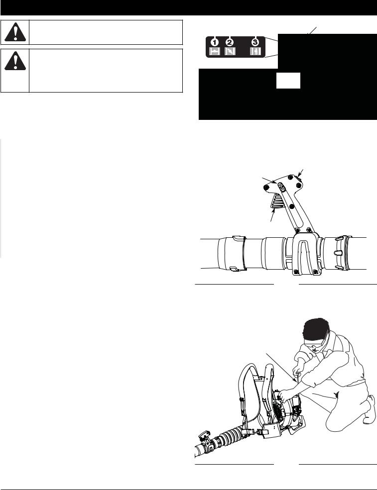
Before beginning, locate the unit’s model plate. It lists the model and serial numbers of your unit. Refer to the sample plate below and copy the information for future reference.
|
MODEL : |
S/N : |
ITEM : |
Copy the model and parent part number here:
Copy the serial number here:
All information, illustrations, and specifications in this manual are based on the latest product information available at the time of printing. We reserve the right to make changes at any time without notice.
Copyright© 2007 MTD SOUTHWEST INC, All Rights Reserved.
(08/07)
RULES FOR SAFE OPERATION
SPARK ARRESTOR NOTE
NOTE: For users on U.S. Forest Land and in the states of California, Maine, Oregon and Washington. All U.S. Forest Land and the state of California (Public Resources Codes 4442 and 4443), Oregon and Washington require, by law that certain internal combustion engines operated on forest brush and/or grass-covered areas be equipped with a spark arrestor, maintained in effective working order, or the engine be constructed, equipped and maintained for the prevention of fire. Check with your state or local authorities for regulations pertaining to these requirements. Failure to follow these requirements could subject you to liability or a fine. This unit is factory equipped with a spark arrestor. If it requires replacement, ask your LOCAL SERVICE DEALER to install the
Accessory Part #753-05297 Spark Arrestor Kit.
CALIFORNIA PROPOSITION 65 WARNING
WARNING
THE ENGINE EXHAUST FROM THIS PRODUCT CONTAINS CHEMICALS KNOWN TO THE STATE OF CALIFORNIA TO CAUSE CANCER, BIRTH DEFECTS OR OTHER REPRODUCTIVE HARM.
The purpose of safety symbols is to attract your attention to possible dangers. The safety symbols, and their explanations, deserve your careful attention and understanding. The safety warnings do not by themselves eliminate any danger. The instructions or warnings they give are not substitutes for proper accident prevention measures.
SYMBOL MEANING
SAFETY ALERT: Indicates danger, warning or caution. Attention is required in order to avoid serious personal injury. May be used in conjunction with other symbols or pictographs.
DANGER: Failure to obey a safety warning will result in serious injury to yourself or to others. Always follow the safety precautions to reduce the risk of fire, electric shock and personal injury.
WARNING: Failure to obey a safety warning can result in injury to yourself and others. Always follow the safety precautions to reduce the risk of fire, electric shock and personal injury.
CAUTION: Failure to obey a safety warning may result in property damage or personal injury to yourself or to others. Always follow the safety precautions to reduce the risk of fire, electric shock and personal injury.
NOTE: Advises you of information or instructions vital to the operation or maintenance of the equipment.
Read the Operator’s Manual and follow all warnings and safety instructions. Failure to do so can result in serious injury to the operator and/or bystanders.
FOR QUESTIONS, CALL 1-877-282-8684 IN U.S. OR 1-800-668-1238 in CANADA
• IMPORTANT SAFETY INSTRUCTIONS •
READ ALL INSTRUCTIONS BEFORE OPERATING
WARNING: When using the unit, you must follow the safety rules. Please read these instructions before operating the unit in order to ensure the safety of the operator and any bystanders. Please keep these instructions for later use.
•Read the instructions carefully. Be familiar with the controls and proper use of the unit.
•Read this operating instruction manual carefully. Be thoroughly familiar with the controls and the proper use of the equipment. Know how to stop the unit and disengage the controls quickly.
•Do not operate this unit when tired, ill, or under the influence of alcohol, drugs, or medication.
•Never allow children to operate the equipment. Never allow adults unfamiliar with the instructions to use the unit. Never allow adults to operate the equipment without proper instruction.
•All guards and safety attachments must be installed properly before operating the unit.
SPECIAL SAFETY WARNINGS FOR GAS ENGINES
WARNING: Gasoline is highly flammable, and its vapors can explode if ignited. Take the following precautions:
•Store fuel only in containers specifically designed and approved for the storage of such materials.
•Always stop the engine and allow it to cool before filling the fuel tank. Never remove the cap of the fuel tank, or add fuel, when the engine is hot. Never operate the unit without the fuel cap securely in place. Loosen the fuel tank cap slowly to relieve any pressure in the tank.
•Add fuel in a clean, well-ventilated area outdoors where there are no sparks or flames. Slowly remove the fuel cap only after stopping engine. Do not smoke while fueling. Wipe up any spilled fuel from the unit immediately.
•Avoid creating a source of ignition for spilled fuel. Do not start the engine until fuel vapors dissipate.
•Move the unit at least 30 feet (9.1 m) from the fueling source and site before starting the engine. Do not smoke. Keep sparks and open flames away from the area while adding fuel or operating the unit.
WHILE OPERATING
•Never start or run the unit inside a closed room or building. Breathing exhaust fumes can kill. Operate this unit only in a wellventilated outdoor area.
•Wear safety glasses or goggles that are marked as meeting ANSI Z87.1 standards and are marked as such. Wear ear/hearing protection when operating this unit.
•Never run the unit without the the proper equipment attached.
•To reduce the risk of hearing loss associated with sound level(s), always wear ear/hearing protection when operating this unit.
•Wear heavy long pants, boots, gloves, and a long sleeve shirt. Do not wear loose clothing, jewelery, short pants, sandals or go barefoot. Secure hair above shoulder level.
•To avoid static electricity shock, do not wear rubber gloves or any other insulated gloves while operating this unit.
•Use the unit only in daylight or good artificial light.
•Keep outside surfaces free from oil and fuel.
•Avoid accidental starting. Be in the starting position whenever pulling the starter rope. The operator and unit must be in a stable position while starting. Refer to Starting/Stopping Instructions.
2

RULES FOR SAFE OPERATION
•Do not set unit on any surface except a clean, hard area while engine is running. Debris such as gravel, sand, dust, grass, etc. could be picked up by the air intake and thrown out by the discharge opening, damaging unit, property, or causing serious injury to bystanders or operator.
•Use the right tool. Only use this tool for its intended purpose.
•Do not force unit. It will do the job better and with less likelihood of injury at a rate for which it was designed.
•Do not overreach or use from unstable surfaces such as ladders, trees, steep slopes, rooftops, etc. Always keep proper footing and balance.
•Always hold the unit with a firm grip when operating.
•Keep hands, face, and feet away from all moving parts. Do not touch or try to stop the impeller when it is rotating. Do not operate without guards in place.
•Do not put any object into openings. Do not use with any opening blocked; keep free of dirt, debris, and anything that may reduce the air flow.
•Do not touch the engine or muffler. These parts get extremely hot from operation, even after the unit is turned off.
•Do not operate the engine faster than the speed needed to do the job. Do not run the engine at high speed when not in use.
•Always stop the engine when operation is delayed or when walking from one location to another.
•Stop the engine for maintenance, repair, to install or remove the blower tubes. The unit must be stopped and the impeller no longer turning to avoid contact with the rotating blades.
•If you strike or come into contact with a foreign object, stop the engine immediately and check for damage. Do not operate before repairing damage. Do not operate the unit with loose or damaged parts.
•Use only replacement parts recommended for this tool that are sold by a Cub Cadet outlet. Use of any replacement parts purchased elsewhere may be hazardous, and will also void your warranty.
•Never use this unit for spreading chemicals, fertilizers or other substances which may contain toxic materials.
•To reduce fire hazard, replace faulty muffler and spark arrestor. Keep the engine and muffler free from grass, leaves, excessive grease or carbon build up.
•Turn the engine off and disconnect the spark plug for maintenance or repair.
•Never point the blower or blowing debris in the direction of people, animals, or in the direction of windows. Always direct the blowing debris away from people, animals, and windows. Use extra caution when blowing debris near solid objects such as trees, automobiles, walls, etc.
OTHER SAFETY WARNINGS
•Always disconnect the spark plug before performing maintenance or accessing movable parts. See Replacing the Spark Plug.
•Never store the unit, with fuel in the tank, inside a building where fumes may reach an open flame (pilot lights, etc.) or sparks (switches, electrical motors, etc.).
•Allow the engine to cool before storing or transporting. Be sure to secure the unit while transporting.
•Store the unit in a dry place, secured, or at a height to prevent unauthorized use or damage. Keep out of the reach of children.
•Never douse or squirt the unit with water or any other liquid. Keep handles dry, clean, and free from debris. Clean after each use, see Cleaning and Storage instructions.
•Keep these instructions. Refer to them often and use them to instruct other users. If you loan this unit to others, also loan these instructions to them.
SPECIAL NOTE: Exposure to vibrations through prolonged use of gasoline powered hand tools could cause blood vessel or nerve damage in the fingers, hands, and joints of people prone to circulation disorders or abnormal swelling. Prolonged use in cold weather has been linked to blood vessel damage in otherwise healthy people. If symptoms occur such as numbness, pain, loss of strength, change in skin color or texture, or loss of feeling in the fingers, hands or joints, discontinue use of this tool and seek medical attention. A reduced vibration system does not guarantee avoidance of these problems. Users who operate power tools on a regular basis must closely monitor their physical condition and the condition of this tool.
SAVE THESE INSTRUCTIONS
3
RULES FOR SAFE OPERATION
SAFETY AND INTERNATIONAL SYMBOLS
This operator's manual describes safety and international symbols and pictographs that may appear on this product. Read the operator's manual for complete safety, assembly, operating, maintenance,` and repair information.
SYMBOL MEANING SYMBOL MEANING
|
• SAFETY ALERT SYMBOL |
|
|
|
|
• ON/OFF STOP CONTROL |
|
|
|
|
|
||
|
Indicates danger, warning or caution. May be used in |
|
|
|
|
ON / START / RUN |
|
conjunction with other symbols or pictographs. |
|
|
|
|
|
|
|
|
|
|
|
|
|
|
|
|
|
|
|
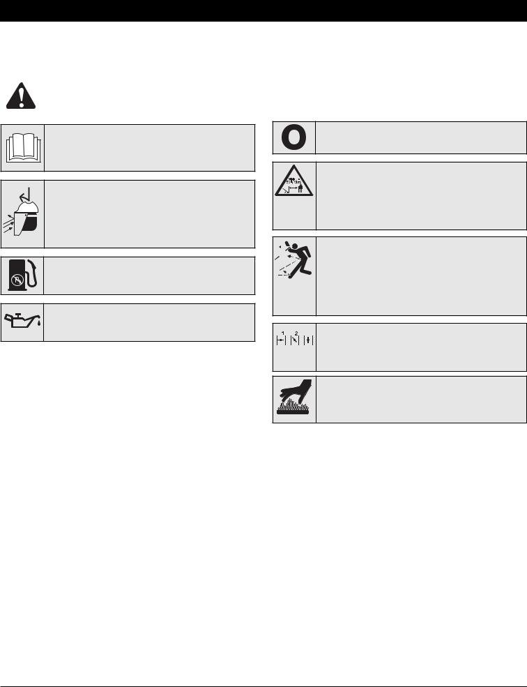
• WARNING: READ OPERATOR'S MANUAL
Read the operator’s manual(s) and follow all warnings and safety instructions. Failure to do so can result in serious injury to the operator and/or bystanders.
• WEAR EYE AND HEARING PROTECTION
WARNING: Thrown objects and loud noise can cause severe eye injury and hearing loss. Wear eye protection meeting ANSI Z87.1 standards and ear protection when operating this unit. Use a full face shield when needed.
• UNLEADED FUEL
Always use clean, fresh unleaded fuel.
• OIL
Refer to operator’s manual for the proper type of oil.
• ON/OFF STOP CONTROL
OFF or STOP
• KEEP BYSTANDERS AWAY
WARNING: Thrown objects and loud noise can cause severe eye injury and hearing loss. Wear eye protection meeting ANSI Z87.1 standards and ear protection when operating this unit. Use a full face shield when needed.
• THROWN OBJECTS CAN CAUSE SEVERE INJURY
WARNING: Thrown objects and loud noise can cause severe eye injury and hearing loss. Wear eye protection meeting ANSI Z87.1 standards and ear protection when operating this unit. Use a full face shield when needed.
 • CHOKE CONTROL
1. • FULL choke position
2.• PARTIAL choke position
3.• RUN choke position
•HOT SURFACE WARNING
Do not touch a hot surface. You may get burned. These parts get extremely hot from operation. They remain hot for a short time after the unit is turned off.
4

KNOW YOUR UNIT
Shoulder Strap
Shoulder Strap
Buckle
Trigger Lock
Throttle Grip
Trigger
Blower
Tube
Nozzle
Choke Lever |
Air Filter Cover |
Harness
Clip
Throttle
Cables
Primer Bulb
Gas Tank 
Oil Fill Plug
Starter Rope
Handle
Gas Cap
Stand
Harness
Muffler
Elbow Tube
5
ASSEMBLY INSTRUCTIONS
ASSEMBLING THE BLOWER TUBE
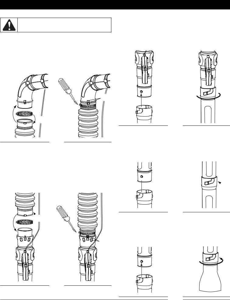
WARNING: To avoid serious personal injury and damage to the unit, shut the unit off before removing or installing the blower tubes.
Installing the Flex Tube
1.Place a hose clamp over the end of the Flex Tube (Fig. 1A).
2.Slide the end of the Flex Tube with the clamp on it over the elbow tube (Fig. 1B).
3.Align the bump on the Flex Tube with the bump on the elbow tube (Fig. 1C).
4.Tighten the screw on the hose clamp to secure the Flex Tube to the elbow tube (Fig. 1D).
Installing the Lower Blower Tubes and Nozzle
1.Align the bump slot on the end of the first lower blower tube with the bump on the bottom end of the upper blower tube (Fig. 3, A).
2.Insert the bump on the upper blower tube into the bump slot on the tube extension (Fig. 3, A).
3.Twist the extension tube clockwise around the upper upper blower tube until the handle tube bump locks into place (Fig. 3, B).
C
D
B
A
Fig. 1
Installing the Upper Blower Tube
1.Place a hose clamp over the other end of the Flex Tube (Fig. 2, A).
2.Slide the end of the hose with the clamp on it over the top end of the upper blower tube (Fig. 2, B).
3.Align the bump on the Flex Tube with the bump on the upper blower tube (Fig. 2, C).
4.Tighten the screw on the hose clamp to secure the Flex Tube to the upper blower tube (Fig. 2, D).
 A
A
B
D 
C
Fig. 2
 B
B
A
Fig. 3
4.Align the bump slot on the end of the second lower blower tube with the bump on the bottom end of the first lower blower tube (Fig. 4, A).
5.Insert the bump on the first lower blower tube into the bump slot on the second lower blower tube (Fig. 4, A).
6.Twist the second lower blower tube clockwise around the first lower blower tube until the second lower blower tube bump locks into place (Fig. 4, B).
 B A
B A 
Fig. 4
7.Align the bump slot on the top end of the nozzle with the bump on the bottom end of the second lower blower tube (Fig. 5, A).
8.Insert the bump on the second lower blower tube into the bump slot on the nozzle (Fig. 5, A).
9.Twist the nozzle clockwise around the second lower blower tube until the nozzle bump locks into place (Fig. 5, B).
B
A
Fig. 5
6

ASSEMBLY INSTRUCTIONS
The completed blower tube should look like Figure 6.
Elbow Tube |
Hose Clamp |
|
Flex Tube
Throttle Cables
Hose Clamp
On/Off Switch
Upper Blower Tube
 Throttle Grip
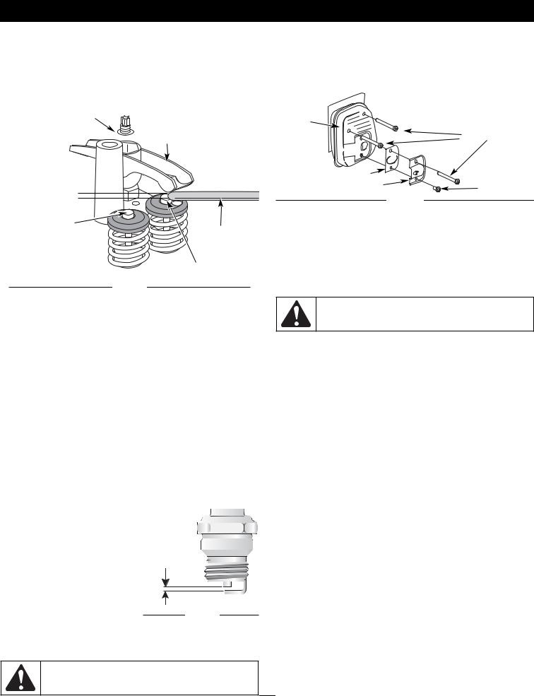
Adjusting the Handle
1.Rotate the throttle grip counterclockwise around the blower tube until it is pointing directly downward (Fig. 7, A).
WARNING: Do not rotate the handle clockwise to adjust. This may cause the throttle cables to disconnect from the throttle grip or the engine.
 B
B
A 
Fig. 7
2.Pull or push the throttle grip along the handle tube until its distance from the backpack blower is comfortable (Fig. 7, B).
3.Align the throttle grip with the slot closest to the comfortable place and rotate the throttle grip clockwise into the upright position (Fig. 8).
First Lower
Blower Tube
Fig. 8
Second Lower
Blower Tube
Nozzle
Fig. 6
WARNING: To avoid serious personal injury, make sure that the blower tubes are locked in place or firmly installed.
7
OIL AND FUEL INFORMATION
WARNING: OVERFILLING OIL CRANKCASE MAY CAUSE SERIOUS PERSONAL INJURY. Check and maintain the proper oil level in the crank case; it is important and cannot be overemphasized. Check the oil before each use while the engine is cold and change it as needed. See Changing the Oil.
RECOMMENDED OIL TYPE
Using the proper type and weight of oil in the crankcase is extremely important. Check oil before each use while the engine is cold and change the oil every 25 hours of operation. Failure to use the correct oil, or using dirty oil, can cause premature engine wear and failure. Use a high-quality SAE 30 weight oil of API (American Petroleum Institute) service class SF, SG, SH.
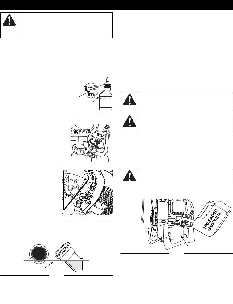
ADDING OIL TO CRANKCASE: INITIAL USE NOTE: This unit is shipped without
oil. In order to avoid damage to the unit, put oil in the crankcase before you attempt to start the unit.
Your unit is supplied with one 3.04 |
Funnel |
|
fluid oz. (90 ml.) bottle of SAE 30 SF, |
Spout |
Fill Level |
SG, SH oil (Fig. 9). |
|
|
NOTE: Save the bottle of oil. It can |
|
Fig. 9 |
be used to measure the |
|
|
correct amount during |
|
Oil Fill Plug |
future oil changes (Fig. 9). O-Ring |
||
See Changing the Oil. |
|
|
1. Unscrew the top of the bottle of oil and remove the paper seal covering the opening. Replace the top. Next, cut the tip off the funnel spout (Fig. 9).
2. Remove the oil fill plug from the crankcase (Fig. 10).
3. |
Tilt the unit 30° to the side |
Oil |
|
|
(Fig. 11). |
10 |
|
4. |
Pour the entire bottle of oil |
||
|
|||
|
into the oil fill hole (Fig. 11). |
30° |
NOTE: Never add oil to the fuel or fuel tank.
5.Wipe up any oil that may have
spilled and reinstall the oil fill plug.
Check oil before each use while the engine is cold and change the oil every 25 hours of operation. Refer to
Checking the Oil Level.
CHECKING THE OIL LEVEL |
|
|
Check the oil only when the engine is |
Fig. 11 |
|
off and cool. |
||
|
1.Place the unit on its stand on a level surface.
2.Remove the oil fill plug from the crankcase (Fig. 10).
3.Look into the oil fill hole (Fig. 10). If the oil level comes up to the first thread, then the oil is full (Fig. 12). If it does not, fill
Oil Full Line
Fig. 12
with oil until it does.
RECOMMENDED FUEL TYPE
Old fuel is the primary reason for improper unit performance. Be sure to use fresh, clean, unleaded gasoline.
NOTE: This is a four cycle engine. In order to avoid damage to the unit, do not mix oil with gasoline.
Definition of Blended Fuels
Today's fuels are often a blend of gasoline and oxygenates such as ethanol, methanol or MTBE (ether). Alcohol-blended fuel absorbs water. As little as 1% water in the fuel can make fuel and oil separate or form acids when stored. Use fresh fuel (less than 60 days old), when using alcohol-blended fuel.
Using Blended Fuels
If you choose to use a blended fuel, or its use is unavoidable, follow recommended precautions:
•Always use fresh unleaded gasoline
•Use the fuel additive STA-BIL® or an equivalent
•Drain tank and run the engine dry before storing unit
WARNING: Add fuel in a clean, well ventilated outdoor area. Wipe up any spilled fuel immediately. Avoid creating a source of ignition for spilt fuel. Do not start the engine until fuel vapors dissipate.
WARNING: Gasoline is extremely flammable. Ignited vapors may explode. Always stop the engine and allow it to cool before filling the fuel tank. Do not smoke while filling the tank. Keep sparks and open flames at a distance from the area.
Using Fuel Additives
The use of fuel additives, such as STA-BIL® Gas Stabilizer or an equivalent, will inhibit corrosion and minimize the formation of gum deposits. Using a fuel additive can keep fuel from forming harmful deposits in the carburetor for up to six (6) months. Add 0.8 oz. (23 ml.) of fuel additive per gallon of fuel according to the instructions on the container. NEVER add fuel additives directly to the unit's gas tank.
WARNING: Remove fuel cap slowly to avoid injury from fuel spray. Never operate the unit without the fuel cap securely in place.
FUELING THE UNIT
1.Remove the fuel cap.
Gas Can
Spout
Fuel Tank
Fig. 13
2.Place the gas container’s spout into the fill hole on the fuel tank (Fig. 13) and fill the tank.
NOTE: Do not overfill the tank.
3.Wipe up any gasoline that may have spilled.
4.Reinstall the fuel cap.
5.Move the unit at least 30 ft. (9.1 m) from the fueling source and site before starting the engine.
NOTE: Dispose of the old gasoline in accordance to Federal, State and Local regulations.
8
STARTING/STOPPING INSTRUCTIONS
WARNING: Operate this unit only in a wellventilated outdoor area. Carbon monoxide exhaust fumes can be lethal in a confined area.
WARNING: Avoid accidental starting. Make sure you are in the starting position when pulling the starter rope (Fig. 16). To avoid serious injury, the operator and unit must be in a stable position while starting.
To avoid serious personal injury, make sure that the blower tube is locked in place or firmly installed.
STARTING INSTRUCTIONS
1.Check the oil level in the crankcase. Refer to Checking the Oil Level.
2.Fill the fuel tank with fresh, clean unleaded gasoline. Refer to Fueling the Unit.

 3. Fully press and release the primer bulb 10 times, slowly. Some amount of fuel should be visible in the primer bulb and fuel lines (Fig. 14). If you can’t see fuel in the bulb, press and release the bulb as many times as it takes before you can see fuel in it.
4.Place the choke lever in Position 1 (Fig. 14).
NOTE: The unit should be started in idle. Do not squeeze the trigger while starting (Fig. 15).
5.Crouch in the starting position and pull the starter rope out about 4 inches, then pull 4 times in smooth and rapid pulls to start engine (Fig. 16).
IF... the engine does not start, place the choke lever in Position 2 (Fig. 14) and pull 4 times in smooth and rapid pulls to start engine.
6.Place the choke lever in Position 2 (Fig. 14) and allow the engine to warm up for 5–10 seconds.
7.Place the choke lever in Position 3 (Fig. 14). The unit is ready for use.

 IF... the engine does not start, follow steps 3 through 7 again.
HOT RESTART: If the unit is already hot, place the choke lever in Position 3 and pull the starter rope to restart.
The unit should be started in idle. Do not squeeze the trigger while starting (Fig. 15).
STOPPING INSTRUCTIONS
1.Release your hand from the trigger. Allow the engine to cool down by idling.
2.Press the On/Off Stop Control switch in the OFF (O) position and hold until the engine comes to a complete stop (Fig. 15).
Choke Lever
Primer 
Bulb
Fig. 14
On/Off Switch
Trigger Lock
Trigger
Fig. 15
Starter Rope
Fig. 16
9
OPERATING INSTRUCTIONS
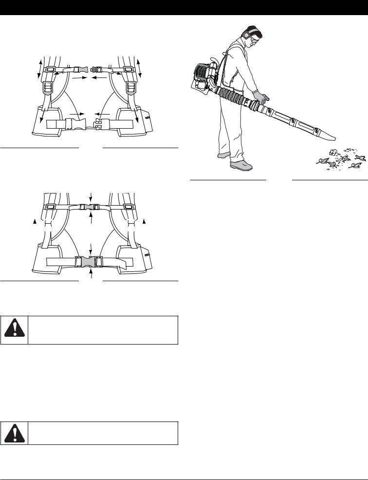
ADJUSTING THE HARNESS
1.Place the unit’s shoulder straps over the shoulders while the unit is behind you.
2.Close the harness belt by sliding the harness clips together (Fig. 17, A).
B B
A
A
B 
 B
B
Fig. 17
3. Pull the harness straps to tighten the shoulder straps (Fig. 17, B).
Releasing the Harness
1.To release the harness, pull up on the shoulder strap buckles (Fig. 18, A).
A
 B
B  A
A
Fig. 18
2.Squeeze the top and bottom of the harness clips to release the harness clips (Fig. 18, B).
HOLDING THE BLOWER
WARNING: To avoid serious personal injury, wear goggles or safety glasses at all times when operating this unit. Wear a face mask or dust mask in dusty locations.
Before operating the unit, stand in the operating position (Fig. 19). Check for the following:
•Operator is wearing proper clothing, such as boots, safety glasses or goggles, ear/hearing protection, gloves, long pants and long sleeve shirt.
•If the conditions are dusty, the operator is wearing a dust mask or face mask.
•The unit is in good working condition.
•The tubes are in place and secure.
OPERATING TIPS
WARNING: To prevent serious personal injury or damage to the unit, make sure blower tubes are in place before you operate the unit.
•Assure the unit is not directed at anybody or any loose debris before starting the unit.
•Verify that the unit is in good working condition. Make sure the tubes are in place and secure.
Fig. 19
•Always hold the unit securely when operating.
•To reduce the risk of hearing loss associated with sound level(s), hearing protection is required.
•Operate power equipment only at reasonable hours— not early in the morning or late at night when people might be disturbed. Comply with times listed in local ordinances. Usual recommendations are 9:00 am to 5:00 pm, Monday through Saturday.
•To reduce noise levels, limit the number of pieces of equipment used at any one time.
•To reduce noise levels, operate power blowers at the lowest possible speed to do the job.
•Check your equipment before operation, especially the muffler, air intakes and air filters.
•Use rakes and brooms to loosen debris before blowing.
•In dusty conditions, slightly dampen surfaces or use a mister attachment when water is available.
•Conserve water by using power blowers instead of hoses for many lawn and garden applications, including areas such as screens, patios, grills, porches, and gardens.
•Watch out for children, pets, open windows or freshly washed cars, and blow debris safely away.
•Use the full blower nozzle extension so the air stream can work close to the ground.
•Clean up after using blowers and other equipment. Dispose of debris appropriately.
•Use the trigger lock (Fig. 15) to keep the trigger depressed while operating to make continuous operation easier.
APPLICATIONS
1Use the blower for trees, shrubs, flower beds and hard-to- clean areas.
2.Use the unit around buildings and for other normal cleaning procedures.
3.Use the blower around walls, overhangs, fences and screens.
10
MAINTENANCE AND REPAIR INSTRUCTIONS
WARNING: To prevent serious injury, never perform maintenance or repairs with unit running. Always service and repair a cool unit. Disconnect the spark plug wire to ensure that the unit cannot start. See
Replacing the Spark Plug.
MAINTENANCE SCHEDULE
Perform these required maintenance procedures at the frequency stated in the table. These procedures should also be a part of any seasonal tune-up.
NOTE: Some maintenance procedures may require special tools or skills. If you are unsure about these procedures take your unit to a Cub Cadet or other qualified service dealer.
NOTE: Maintenance, replacement, or repair of the emission control devices and system may be performed by a Cub Cadet or other qualified service dealer.
In order to assure peak performance of your engine, inspection of the engine exhaust port may be necessary after 50 hours of operation. If you notice lost RPM, poor performance or general lack of acceleration, this service may be required. If you feel your engine is in need of this inspection, refer service to a Cub Cadet or other qualified service dealer for repair. DO NOT attempt to perform this process yourself as engine damage may result from contaminants involved in the cleaning process for the port.
FREQUENCY |
MAINTENANCE REQUIRED |
SEE |
|
|
|
|
|
Before using |
Fill fuel tank with fresh fuel |
p 8 |
|
Check oil while the engine is cold |
p 8 |
||
|
|||
|
|
|
|
Every 25 hrs |
Change oil |
p 11 |
|
Every 25 hrs |
Clean and re-oil air filter |
p 11 |
|
Every 25 hrs |
Check rocker arm clearance and adjust |
p 12 |
|
Every 25 hrs |
Check spark plug condition and gap |
p 13 |
|
|
|
|
|
Every 50 hrs |
Clean spark arrestor |
p 13 |
|
|
|
|
CHANGING THE OIL
Change the oil every 25 hours of operation. Change the oil while the engine is still warm. The oil will flow freely and carry away more impurities.
WARNING: Wear gloves to prevent injury when handling unit.
1.Remove the oil fill plug.
2.Pour the oil out of the oil fill hole and into a container by tipping the unit to the side (Fig. 20). Allow ample time for complete drainage.
3.Wipe up any oil residue on the unit and clean up any oil that may have spilled. Dispose of the oil according to Federal, State and local regulations.
4.Tilt the unit 30° to the side (Fig. 11).
5.Refill the crankcase with 3.04 fluid ounce (90 ml) of
SAE 30 SF, SG, SH oil. |
|
Fig. 20 |
|
NOTE: Use the bottle and
spout saved from initial use to measure the correct amount of oil. The top of the label on the bottle measures approximately 3.04 ounces (90 ml) (Fig. 21). Check the level, See Checking the Oil Level. If the level is low, add a small amount of oil and recheck. Do not overfill (Fig. 21).
6.Replace the oil fill plug.
WARNING: To avoid serious personal injury, always turn the unit off and allow it to cool before you clean or service it.
30°
Fill Level
Fig. 21
AIR FILTER MAINTENANCE Cleaning the Air Filter
Clean and re-oil the air filter every 25 hours of operation. It is an important item to maintain. Failure to maintain your air filter properly can result in poor performance or can cause permanent damage to your engine.
1.Open the air filter cover. Push the locking tab on the under side of the cover inward. Then pull the air filter cover out and up. (Fig. 22).
Air Filter Cover
Locking
Tab
Fig. 22
2.Remove the air filter (Fig. 23).
Air Filter |
Tabs |
Back Plate
 Locking Tab
Fig. 23
3.Wash the filter in detergent and
water (Fig. 24). Rinse the filter thoroughly and allow it to dry.
4. Apply enough clean SAE 30 motor oil to lightly coat the filter (Fig. 25).
5. Squeeze the filter to spread and remove excess oil (Fig. 26).
6.Replace the filter (Fig. 23).
NOTE: If the unit is operated without the air filter, you will VOID the
warranty.
Fig. 24
11

MAINTENANCE AND REPAIR INSTRUCTIONS
ROCKER ARM CLEARANCE
This requires disassembly of the engine. If you feel unsure or unqualified to perform this, take the unit to an authorized service center.
NOTE: Inspect the valve to rocker arm clearance with a feeler gauge after every 25 hours of operation.
• The engine must be cold when checking or adjusting the valve clearance.
•This task should be performed inside, in a clean, dust free area.
1.Remove the eight (8) screws on the back of the engine cover
with a Flat-head or T-25 Torx screwdriver (Fig. 29).
Fig. 25 |
|
|
|
Fig. 26 |
|
|
|
Air Filter Cover
Air Filter
Back Plate
 Tab
Tab
Fig. 27
7.Reinstall the air filter cover. Position the slots on the top of the air filter cover onto the tabs at the top of the back plate (Figs. 23 & 27).
8.Swing the cover down until the tab on the air filter backplate snaps into place in the slot on the air filter cover (Fig. 27).
CARBURETOR ADJUSTMENT |
|
The idle speed of the engine is |
Idle |
adjustable. An idle adjustment screw |
|
is between the air filter cover and the |
Adjustment |
engine starter housing (Fig. 28). |
Screw |
NOTE: Careless adjustments can |
|
seriously damage your unit. |
|
An authorized service |
|
dealer should make |
|
carburetor adjustments. |
|
Check Fuel
Old fuel is usually the reason for improper unit performance. Drain
and refill the tank with fresh fuel
prior to making any adjustments. Refer to Oil and Fuel Information.
Clean Air Filter
The condition of the air filter is important to the operation of the unit. A dirty air filter will restrict air flow. This is often mistaken for an out of adjustment carburetor. Check the condition of the air filter before adjusting the idle speed screw. Refer to Air Filter Maintenance.
Adjust Idle Speed Screw
If, after checking the fuel and cleaning the air filter, the engine still will not idle, adjust the idle speed screw as follows:
1.Start the engine and let it run at a high idle for a minute to warm up. Refer to Starting/Stopping Instructions.
2.Release the throttle trigger and let the engine idle. If the engine stops, insert a small phillips in between the Air Filter Cover and the Engine Cover (Fig. 28). Turn the idle speed screw in, clockwise, 1/8 of a turn at a time (as needed) until the engine idles smoothly.
Checking the fuel, cleaning the air filter, and adjusting the idle speed should solve most engine problems. If not and all of the following are true:
•the engine will not idle
•the engine hesitates or stalls on acceleration
•there is a loss of engine power
Have the carburetor adjusted by an authorized service dealer.
Remove
Screws Remove
Screws
Fig. 29
2.Disconnect the spark plug wire.
3.Clean dirt from around the spark plug. Remove the spark plug from the cylinder head by turning a 5/8 in. socket counterclockwise.
4.Remove the engine cover (Fig. 29).
5.Clean dirt from around the rocker
arm cover. Remove the screw |
Rocker |
|
holding the rocker arm cover with a |
Arm |
|
large flat blade screwdriver or Torx T- |
Cover |
|
25 bit (Fig. 30). Remove the rocker |
|
|
arm cover and gasket. |
|
|
6. Pull the starter rope slowly to bring |
Spark |
|
the piston to the top of its travel, |
||
Plug |
||
(known as top dead center). Check |
||
Hole |
||
that: |
||
|
||
• The piston is at the top of its travel |
|
|
while looking in the spark plug hole |
|
|
(Fig. 31). |
|
|
• Both rocker arms move freely, and |
Fig. 30 |
|
both valves are closed. |
||
|
If these statements are not true, repeat this step.
Rocker Arms |
INTAKE |
Adjusting Nuts |
|
||
|
|
EXHAUST
Feeler Gauge
Spark Plug Hole
Fig. 31
12
MAINTENANCE AND REPAIR INSTRUCTIONS
7.Slide the feeler gauge between the rocker arm and the valve return spring. Measure the clearance between the valve stem and rocker arm (Fig. 31). Measure both the intake and exhaust valves.
The recommended clearance for both intake and exhaust is .003 –
.006 in. (.076 – 0.152 mm). Use a standard automotive .005 in. (0.127 mm) feeler gauge. The feeler gauge should slide between the rocker arm and valve stem with a slight amount of resistance, without binding. See Figures 31 and 32.
Adjusting Nut

 Rocker Arm
.003–.006 in. |
|
|
(.076–.152 mm) |
|
|
Intake Valve |
Feeler Gauge |
|
Stem |
||
|
||
|
Valve Stem |
Fig. 32
8.If the clearance is not within specification:
a.Turn the adjusting nut using a 5/16 inch (8 mm) wrench or nut driver (Fig. 31).
•To increase clearance, turn the adjusting nut counterclockwise.
•To decrease clearance, turn the adjusting nut clockwise.
b.Recheck both clearances, and adjust as necessary.
9.Reinstall the rocker arm cover using a new gasket. Torque the screw to 20–30 in•lb (2.2–3.4 N•m).
10.Check the spark plug and reinstall. See Replacing the Spark Plug.
11.Replace the spark plug wire.
12.Reinstall the engine cover. Check alignment of the cover before tightening the screws. Tighten screws.
REPLACING THE SPARK PLUG
Use a replacement part number 753-05255 spark plug. The correct air gap is 0.025 in. (0.635 mm.). Remove the plug after every 25 hours of operation and check its condition.
1.Stop the engine and allow it to cool. Remove the eight (8) screws on the back of the engine cover with a Flat-head or T- 25 Torx screwdriver (Fig. 29).
2.Grasp the plug wire firmly and pull the cap from the spark plug.
3.Clean dirt from around the spark plug. Remove the spark plug from the cylinder head by turning a 5/8 in. socket counterclockwise.
4.Replace cracked, fouled or dirty spark plug. Set the air gap at 0.025 in. (0.635 mm.) using a feeler gauge (Fig. 33).
5.Install a correctly-gapped spark plug in the cylinder head. Turn the 5/8 in. socket clockwise until snug.
If using a torque wrench torque to:
110-120 in.•lb. (12.3-13.5 N•m) Do not over tighten.
0.025 in.
(0.635 mm.)
Fig. 33
WARNING: Do not sand blast, scrape or clean electrodes. Grit in the engine could damage the cylinder.
SPARK ARRESTOR MAINTENANCE
Inspect the spark arrestor after every 50 hours of operation.
1.Remove the rear engine cover. See Rocker Arm Clearance.
2.With a flat blade screwdriver or Torx T-20 bit and a T-25 bit, remove the 4 screws attaching the spark arrestor cover to the muffler (Fig. 34).
Muffler
T-25 Screws
Slot 
Spark Arrestor Screen |
|
Diverter |
T-20 Screw |
|
Fig. 34 |
3.Pull the tab on the spark arrestor cover out of the muffler. Remove the spark arrestor cover.
4.Remove the spark arrestor screen from the spark arrestor cover.
5.Clean the spark arrestor screen with a wire brush or replace it.
6.Reinstall the spark arrestor screen, spark arrestor cover and screws.
CLEANING
WARNING: To avoid serious personal injury, always turn your unit off and allow it to cool before you clean or service it.
Use a small brush to clean off the outside of the unit. Do not use strong detergents. Household cleaners that contain aromatic oils such as pine and lemon, and solvents such as kerosene, can damage plastic housing or handle. Wipe off any moisture with a soft cloth.
STORAGE
•Never store the unit with fuel in the tank where fumes may reach an open flame or spark.
•Allow the engine to cool before storing.
•Lock up the unit to prevent unauthorized use or damage.
•Store the unit in a dry, well-ventilated area.
•Store the unit out of the reach of children.
LONG TERM STORAGE
1.Drain all gasoline from the gas tank into a container. Do not use gas that has been stored for more than 60 days. Dispose of the old gasoline in accordance to Federal, State, and Local regulations.
2.Start the engine and allow it to run until it stalls. This ensures that all gasoline has been drained from the carburetor.
3.Allow the engine to cool. Remove the eight (8) screws on the back of the engine cover with a Flat-head or T-25 Torx screwdriver. Remove the spark plug and put 5 drops of high quality motor oil into the cylinder. Pull the starter rope slowly to distribute the oil. Reinstall the spark plug.
NOTE: Remove the spark plug and drain all of the oil from the cylinder before attempting to start the blower after storage.
4.Change the oil, referring to Changing the Oil. Dispose of the old oil in accordance to Federal, State and Local regulations.
5.Thoroughly clean the unit and inspect for any loose or damaged parts. Repair or replace damaged parts and tighten loose screws, nuts or bolts. The unit is ready for storage.
TRANSPORTING
•Allow the engine to cool before transporting.
•Secure the unit while transporting.
•Drain the gas tank before transporting.
•Tighten gas cap before transporting.
13

|
|
TROUBLESHOOTING |
||
|
|
|
|
|
|
|
|
|
|
|
ENGINE WILL NOT START |
|
|
|
|
|
|
|
|
|
C A U S E |
|
A C T I O N |
|
|
Empty fuel tank |
|
Fill fuel tank with fuel |
|
|
|
|
|
|
|
Primer bulb wasn't pressed enough |
|
Press primer bulb fully and slowly 10 times |
|
|
Old fuel |
|
Drain gas tank and add fresh fuel |
|
|
|
|
|
|
|
Fouled spark plug |
|
Replace or clean the spark plug |
|
|
Plugged spark arrestor |
|
Clean or replace spark arrestor |
|
|
|
|
|
|
|
ENGINE WILL NOT IDLE |
|
|
|
|
|
|
|
|
|
C A U S E |
|
A C T I O N |
|
|
Air filter is plugged |
|
Replace or clean the air filter |
|
|
|
|
|
|
|
Old fuel |
|
Drain gas tank and add fresh fuel |
|
|
Improper carburetor adjustment |
|
Adjust according to the Carburetor Adjustments section or take to |
|
|
|
|
an authorized service dealer for an adjustment |
|
|
|
|
|
|
|
ENGINE WILL NOT ACCELERATE |
|
|
|
|
|
|
|
|
|
C A U S E |
|
A C T I O N |
|
|
Old fuel |
|
Drain gas tank and add fresh fuel |
|
|
|
|
|
|
|
Improper carburetor adjustment |
|
Adjust according to the Carburetor Adjustments section or take to |
|
|
|
|
an authorized service dealer for an adjustment |
|
|
Dirty air filter |
|
Clean or replace the air filter |
|
|
|
|
|
|
|
Plugged spark arrestor |
|
Clean or replace spark arrestor |
|
|
ENGINE LACKS POWER OR STALLS |
|
|
|
|
|
|
|
|
|
C A U S E |
|
A C T I O N |
|
|
Old fuel |
|
Drain gas tank and add fresh fuel |
|
|
|
|
|
|
|
Improper carburetor adjustment |
|
Adjust according to the Carburetor Adjustments section or take to |
|
|
|
|
an authorized service dealer for an adjustment |
|
|
Fouled spark plug |
|
Replace or clean the spark plug |
|
|
|
|
|
|
|
Plugged spark arrestor |
|
Clean or replace spark arrestor |
|
|
|
|
|
|
If further assistance is required, contact your authorized service dealer.
14

SPECIFICATIONS
ENGINE*
Engine Type . . . . . . . . . . . . . . . . . . . . . . . . . . . . . . . . . . . . . . . . . . . . . . . . . . . . . . . . . . . . . . . . . . . . . . . . . . . . . . . . . . . . . . Air-Cooled, 4-Cycle Displacement . . . . . . . . . . . . . . . . . . . . . . . . . . . . . . . . . . . . . . . . . . . . . . . . . . . . . . . . . . . . . . . . . . . . . . . . . . . . . . . . . . . . . . . . 1.95 in.3 (32 cc) Operating RPM . . . . . . . . . . . . . . . . . . . . . . . . . . . . . . . . . . . . . . . . . . . . . . . . . . . . . . . . . . . . . . . . . . . . . . . . . . . . . . . . . . . . . . 5,500–6,500 rpm Idle Speed RPM . . . . . . . . . . . . . . . . . . . . . . . . . . . . . . . . . . . . . . . . . . . . . . . . . . . . . . . . . . . . . . . . . . . . . . . . . . . . . . . . . . . . . 3,800–4,400 rpm Ignition Type . . . . . . . . . . . . . . . . . . . . . . . . . . . . . . . . . . . . . . . . . . . . . . . . . . . . . . . . . . . . . . . . . . . . . . . . . . . . . . . . . . . . . . . . . . . . . . Electronic Ignition Switch . . . . . . . . . . . . . . . . . . . . . . . . . . . . . . . . . . . . . . . . . . . . . . . . . . . . . . . . . . . . . . . . . . . . . . . . . . . . . . . . . . . . . . . . Rocker Switch Valve clearance . . . . . . . . . . . . . . . . . . . . . . . . . . . . . . . . . . . . . . . . . . . . . . . . . . . . . . . . . . . . . . . . . . . . . . . . 0.003–0.006 in. (0.076–0.152 mm) Spark Plug Gap . . . . . . . . . . . . . . . . . . . . . . . . . . . . . . . . . . . . . . . . . . . . . . . . . . . . . . . . . . . . . . . . . . . . . . . . . . . . . . . . . 0.025 inch (0.635 mm) Lubrication . . . . . . . . . . . . . . . . . . . . . . . . . . . . . . . . . . . . . . . . . . . . . . . . . . . . . . . . . . . . . . . . . . . . . . . . . . . . . . . . . . . . . . . . . . . . . . SAE 30 Oil Crankcase Oil Capacity . . . . . . . . . . . . . . . . . . . . . . . . . . . . . . . . . . . . . . . . . . . . . . . . . . . . . . . . . . . . . . . . . . . . . . . . . . . . . . . . . 3.04 oz (90 ml) Fuel . . . . . . . . . . . . . . . . . . . . . . . . . . . . . . . . . . . . . . . . . . . . . . . . . . . . . . . . . . . . . . . . . . . . . . . . . . . . . . . . . . . . . . . . . . . . . . . . . . . . Unleaded Carburetor . . . . . . . . . . . . . . . . . . . . . . . . . . . . . . . . . . . . . . . . . . . . . . . . . . . . . . . . . . . . . . . . . . . . . . . . . . . . . . . . . . . . Diaphragm, All-Position Starter . . . . . . . . . . . . . . . . . . . . . . . . . . . . . . . . . . . . . . . . . . . . . . . . . . . . . . . . . . . . . . . . . . . . . . . . . . . . . . . . . . . . . . . . . . . . . . . . Auto Rewind Muffler . . . . . . . . . . . . . . . . . . . . . . . . . . . . . . . . . . . . . . . . . . . . . . . . . . . . . . . . . . . . . . . . . . . . . . . . . . . . . . . . . . . . . . . . . . . . Baffled with Guard Throttle . . . . . . . . . . . . . . . . . . . . . . . . . . . . . . . . . . . . . . . . . . . . . . . . . . . . . . . . . . . . . . . . . . . . . . . . . . . . . . . . . . . . . . . . Manual Spring Return Fuel Tank Capacity . . . . . . . . . . . . . . . . . . . . . . . . . . . . . . . . . . . . . . . . . . . . . . . . . . . . . . . . . . . . . . . . . . . . . . . . . . . . . . . . . . . . . 26 oz (769 ml)
*All specifications are based on the latest product information available at the time of printing. We reserve the right to make changes at any time without notice.
15

CALIFORNIA / EPA EMISSION CONTROL WARRANTY STATEMENT
Your Warranty Rights and Obligations
The California Air Resources Board, the Environmental Protection Agency, and Cub Cadet LLC (Cub Cadet) are pleased to explain the emission control system warranty on your 2007 and later small off-road engine. In California and the 49 states, new small off-road engines must be designed, built and equipped to meet the state’s stringent anti-smog standards. Cub Cadet must warrant the emission control system on your small off-road engine for the periods of time listed below provided there has been no abuse, neglect or improper maintenance of your small off-road engine.
Your emission control system may include parts such as the carburetor or fuel-injection system, the ignition system, and catalytic converter. Also included may be hoses, belts, connectors and other emission-related assemblies.
Where a warrantable condition exists, Cub Cadet will repair your small off-road engine at no cost to you including diagnosis, parts and labor.
The 2007 and later small off-road engines are warranted for two years. If any emission-related part on your engine is defective, the part will be repaired or replaced by Cub Cadet.
Owners Warranty Responsibilities
As the small off-road engine owner, you are responsible for the performance of the required maintenance listed in your operator’s manual. Cub Cadet recommends that you retain all receipts covering maintenance on your small off-road engine, but Cub Cadet cannot deny warranty solely for the lack of receipts or for your failure to ensure the performance of all scheduled maintenance.
•As the small off-road engine owner, you should however be aware that Cub Cadet may deny you warranty coverage if your small off-road engine or a part has failed due to abuse, neglect, improper maintenance or unapproved modifications.
•You are responsible for presenting your small off-road engine to a Cub Cadet Authorized Service Center as soon as a problem exists. The warranty repairs should be completed in a reasonable amount of time, not to exceed 30 days.
If you have any questions regarding your warranty rights and responsibilities, you should call 1-877-282-8684.
Manufacturer’s Warranty Coverage
•The warranty period begins on the date the engine or equipment is delivered to the retail purchaser.
•The manufacturer warrants to the initial owner and each subsequent purchaser, that the engine is free from defects in material and workmanship which cause the failure of a warranted part for a period of two years.
•Repair or replacement of warranted part will be performed at no charge to the owner at an Authorized Cub Cadet Service Center. For the nearest location please contact Cub Cadet at: 1-877-282-8684.
•Any warranted part which is not scheduled for replacement, as required maintenance or which is scheduled for only for regular inspection to the effect of “Repair or Replace as Necessary” is warranted for the warranty period. Any warranted part which is scheduled for replacement as required maintenance will be warranted for the period of time up to the first scheduled replacement point for that part.
•The owner will not be charged for diagnostic labor which leads to the determination that a warranted part is defective, if the diagnostic work is performed at an Authorized Cub Cadet Service Center.
•The manufacturer is liable for damages to other engine components caused by the failure of a warranted part still under warranty.
•Failures caused by abuse, neglect or improper maintenance are not covered under warranty.
•The use of add-on or modified parts can be grounds for disallowing a warranty claim. The manufacturer is not liable to cover failures of warranted parts caused by the use of add-on or modified parts.
•In order to file a claim, go to your nearest Authorized Cub Cadet Service Center. Warranty services or repairs will be provided at all Authorized Cub Cadet Service Centers.
•Any manufacturer approved replacement part may be used in the performance of any warranty maintenance or repair of emission related parts and will be provided without charge to the owner. Any replacement part that is equivalent in performance or durability may be used in non-warranty maintenance or repair and will not reduce the warranty obligations of the manufacturer.
Emission Warranty Parts List:
The following components are included in the emission-related warranty of the engine: air filter, carburetor, primer, fuel lines, fuel pick up/ fuel filter, ignition module, spark plug, and muffler. Valves and Cam are additionally included if your engine is a 4-Stroke Model.
16

CALIFORNIA EVAPORATIVE EMISSION CONTROL WARRANTY STATEMENT
Your Warranty Rights and Obligations
The California Air Resources Board and Cub Cadet LLC (Cub Cadet) is pleased to explain the evaporative emission control system’s warranty on your 2007 model year and later small off-road (equipment type) engine. In California, new equipment that use small off-engines must be designed, built, and equipped to meet the State’s stringent anti-smog standards Cub Cadet must warrant the evaporative emission control system on your small off-road Lawn & Garden engine for the period listed below provided there has been no abuse, neglect or improper maintenance of your equipment.
Your evaporative emission control system may include parts such as: carburetors, fuel tanks, fuel lines, fuel caps, valves, canisters, filters, vapor hoses, clamps, connectors, and other associated components. For engines less than or equal to 80 cc, only the fuel tank is subject to the evaporative emission control warranty requirements of this section. The displacement of your small off road engine is less than 80 cc.
Manufacturer’s Warranty Coverage
This evaporative emission control system is warranted for two years. If any evaporative emission-related part on your equipment is defective, the part will be repaired or replaced by Cub Cadet.
Owner’s Warranty Responsibilities
•As the small off-road Lawn & Garden engine owner, you are responsible for performance of the required maintenance listed in your owner’s manual. Cub Cadet recommends that you retain all receipts covering maintenance on your Lawn & Garden Engine but Cub Cadet cannot deny warranty solely for the lack of receipts.
•As the small off-road Lawn & Garden engine owner, you should however be aware that the Cub Cadet may deny you warranty coverage if your fuel tank has failed due to abuse, neglect, or improper maintenance or unapproved modifications.
•You are responsible for presenting your Lawn & Garden fuel tank to Cub Cadet distribution center or service center as soon as the problem exists. The warranty repairs should be completed in a reasonable amount of time, not to exceed 30 days. If you have a question regarding your warranty coverage, you should contact Cub Cadet at 1-877-282-8684.
Defects Warranty Requirements
(a)The warranty period begins on the date the engine or equipment is delivered to an ultimate purchaser.
(b)General Evaporative Emissions Warranty Coverage. The fuel tank must be warranted to the ultimate purchaser and any subsequent owner that the evaporative emission control system when installed was:
(1)Designed, built, and equipped so as to conform with all applicable regulations; and
(2)Free from defects in materials and workmanship that causes the failure of a warranted part for a period of two years.
(c) The warranty on evaporative emissions-related parts will be interpreted as follows:
(1)Any warranted part that is not scheduled for replacement as required maintenance in the written instructions must be warranted for the warranty period defined in subsection (b)(2). If any such part fails during the period of warranty coverage, it must be repaired or replaced by Cub Cadet. Any such part repaired or replaced under the warranty must be warranted for a time not less than the remaining warranty period.
(2)Any warranted part that is scheduled only for regular inspection in the written instructions must be warranted for the warranty period defined in subsection (b)(2). A statement in such written instructions to the effect of “repair or replace as necessary” will not reduce the period of warranty coverage. Any such part repaired or replaced under warranty must be warranted for a time not less than the remaining warranty period.
(3)Any warranted part that is scheduled for replacement as required maintenance in the written instructions must be warranted for the period of time prior to the first scheduled replacement point for that part. If the part fails prior to the first scheduled replacement, the part must be repaired or replaced by the Cub Cadet. Any such part repaired or replaced under warranty must be warranted for a time not less than the remainder of the period prior to the first scheduled replacement point for the part.
(4)Repair or replacement of any warranted part under the warranty provisions of this article must be performed at no charge to the owner at a warranty station.
(5)Not withstanding the provisions of subsection (4) above, warranty services or repairs must be provided at distribution centers that are franchised to service the subject engines or equipment.
(6)The owner must not be charged for diagnostic labor that leads to the determination that a warranted part is in fact defective, provided that such diagnostic work is performed at a warranty station.
(7)Throughout the evaporative emission control system’s warranty period set out in subsection (b)(2), Cub Cadet must maintain a supply of warranted parts sufficient to meet the expected demand for such parts.
(8)Manufacturer approved replacement parts must be used in the performance of any warranty maintenance or repairs and must be provided without charge to the owner. Such use will not reduce the warranty obligations of the manufacturer issuing the warranty.
(9)The use of any add-on or modified parts will be grounds for disallowing a warranty claim made in accordance with this article. The manufacturer issuing the warranty will not be liable under this Article to warrant failures of warranted parts caused by the use of an add-on or modified part.
(10)Cub Cadet shall provide any documents that describe the warranty procedures or policies within five working days of request by the Air Resources Board.
Emission Warranty Parts List
(1) Fuel Tank
Written instructions for the maintenance and use of the evaporative emissions control system by the owner shall be furnished with each new engine or equipment.
17
 Loading...