


GT-2544

GT 2544
SERIES 2500
OPERATOR’S MANUAL
IMPORTANT: READ SAFETY RULES AND INSTRUCTIONS CAREFULLY
CUB CADET LLC P.O. BOX 361131 CLEVELAND, OHIO 44136-0019 [ www.cubcadet.com]
PRINTED IN U.S.A.
Warning:
This unit is equipped with an internal combustion engine and should not be used on or near any unimproved forest-
covered, brush-covered or grass-covered land unless the engine’s exhaust system is equipped with a spark arrester meeting
applicable local or state laws (if any). If a spark arrester is used, it should be maintained in effective working order by the operator.
In the State of California the above is required by law (Section 4442 of the California Public Resources Code). Other states may have
similar laws. Federal laws apply on federal lands. A spark arrester for the muffler is available through your nearest engine authorized
service dealer or contact the service department, P.O. Box 361131 Cleveland, Ohio 44136-0019.
FORM NO. 769-02068C
TRACTOR
Model Number
(11/06)

2
TABLE OF CONTENTS
Section Page
Tractor and Deck Preparation ............. 3
Safe Operation Practices..................... 4
Product Graphics................................. 8
Slope Gauge ....................................... 9
To The Owner...................................... 10
Calling Service Information.................. 10
Recording Model & Serial Number ...... 10
I Know Your Tractor .............................. 11
II Operation............................................. 15
III Adjustments......................................... 20
IV Maintenance ........................................ 25
V Mower Deck......................................... 33
VI Off-Season Storage............................. 43
VII Mowing ................................................ 44
Optional Equipment and Accessories. 45
Lubrication .......................................... 45
Maintenance Chart .............................. 46
Lubrication Table ................................. 47
Lubrication Guide ................................ 48
Trouble Shooting ................................. 50
Specifications ...................................... 52
Emission Control Systems Warranty ... 53
Warranty ............................................. 54
Maintenance Parts Chart .................... 56
3
TRACTOR AND DECK PREPARATION
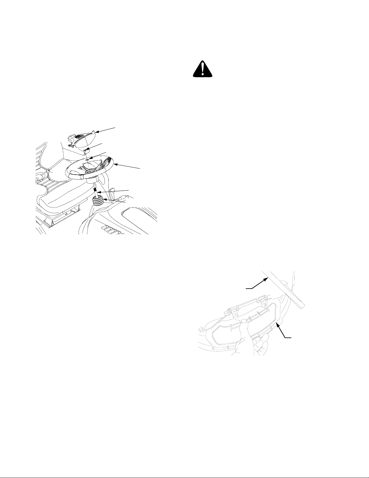
1. TRACTOR STEERING WHEEL
For shipping purposes, the steering wheel was removed
from the steering shaft. Pivot the seat rearward and re-
move any packaging material from the seat. Cut the ties
securing the steering wheel and remove any packaging
material. Install the steering wheel as follows:
1. Locate the steering bellow and note the riser at one
end of the bellow. With the riser facing upward, slide
the bellow onto the steering shaft. See Figure 1.
Figure 1
2. Pry the steering wheel cover off the steering wheel
and remove the hex lock screw and flat washer.
3. Check that the tractor front tires are in the straight
position. If not, temporarily slide the steering wheel
onto the steering shaft and straighten the front
wheels. Carefully remove the steering wheel.
4. From the operator’s seat, rotate the steering wheel
so that the spokes of the wheel are in the basic ‘T’
position. Align the splines of the steering wheel
hub with the splines of the steering shaft and press
the steering wheel onto the shaft.
5. Position the steering bellow so that its riser is
inside the bottom of the steering wheel.
6. Slide the flat washer onto the hex lock screw.
Insert the screw through the center hole of the
steering wheel and thread into the steering shaft.
Fully tighten the lock screw into the steering shaft.
7. Position the steering wheel cover to align with the
steering wheel. Press the cover downward until it
snaps into place on the steering wheel.
2. CONNECT THE BATTERY
WARNING: Battery posts, terminals and
related accessories contain lead and lead
compounds. Wash hands after handling.
The tractor is shipped with an activated sealed battery.
The positive battery cable is factory connected. The
negative cable must be connected.
Note: Make sure the ignition switch is in the "OFF" po-
sition before attaching the battery cables.
1. Pull the protective cap, if present, off the negative
terminal of the battery, and remove the hex cap
screw and nut from the free end of the negative bat-
tery cable.
2. Connect the negative battery cable (black) and
green ground wire to the negative terminal (NEG)
of the battery using the hex cap screw and nut.
3. Slide the black terminal cover over the negative
terminal of the battery.
3. MULCHING PLUG
For shipping the mulching plug may be packed with the
owner’s manual, or may be installed in the deck.
If installed in the deck, remove the mulching plug as
follows:
• Raise the chute deflector and lift the mulching plug up-
ward, then outward to remove from the deck. Lower
the chute deflector. See Figure 2.
Figure 2
Store the mulching plug for future use.
Refer to Section V - Mower Deck for instructions on in-
stalling and using the mulching plug.
STEERING WHEEL
COVER
HEX LOCK SCREW
FLAT WASHER
STEERING
STEERING SHAFT
STEERING BELLOW
WHEEL
RAISE CHUTE
DEFLECTOR
LIFT MULCHING
PLUG UP AND
OUT

4
WARNING
• The engine exhaust, some of its constituents, and certain vehicle components contain or emit chemicals known
to the State of California to cause cancer, birth defects or other reproductive harm.
• This unit is equipped with an internal combustion engine and should not be used on or near any unimproved
forest-covered, brush-covered, or grass-covered land unless the engine’s exhaust system is equipped with a
spark arrester meeting applicable local or state laws (if any). If a spark arrester is used, it should be maintained
in effective working order by the operator.
• In the State of California, the above is required by law (Section 4442 of the California Public Resources Code).
Other States may have similar laws. Federal laws apply to federal lands. A spark arrester muffler is available
at your nearest engine authorized service center.
IMPORTANT
THIS SYMBOL POINTS OUT IMPORTANT SAFETY INSTRUCTIONS WHICH, IF NOT FOLLOWED,
COULD ENDANGER THE PERSONAL SAFETY AND/OR PROPERTY OF YOURSELF AND
OTHERS. READ AND FOLLOW ALL INSTRUCTIONS IN THIS MANUAL BEFORE ATTEMPTING
TO OPERATE THIS MACHINE. FAILURE TO COMPLY WITH THESE INSTRUCTIONS MAY
RESULT IN PERSONAL INJURY. WHEN YOU SEE THIS SYMBOL — HEED ITS WARNING.
SAFE OPERATION PRACTICES
Your lawn mower was built to be operated according to the rules for safe operation
in this manual. As with any type of power equipment, carelessness or error on the
part of the operator can result in injury. This lawn mower is capable of amputating
hands and feet or throwing objects. Failure to observe the following safety
instructions could result in serious injury or death.
I. GENERAL OPERATION
1. Read, understand and follow all instructions in the
manual and on the machine before starting and op-
erating the machine. Keep this manual in a safe
place for future and regular reference.
2. Be familiar with all controls and their proper opera-
tion. Know how to stop the machine and disengage
them quickly.
3. Never allow children under 14 years old to operate
this machine. Children 14 years old and over should
read and understand the operation instructions and
safety rules in this manual and should be trained
and supervised by a parent.
4. Never allow adults to operate this machine without
proper instruction.
5. To help avoid blade contact or a thrown object inju-
ry, keep bystanders, helpers, children and pets at
least 75 feet from the machine while it is in opera-
tion. Stop machine if anyone enters the area.
6. Thoroughly inspect the area where the equipment
is to be used. Remove all stones, sticks, wire,
bones, toys, and other foreign objects which could
be picked up and thrown by the blade(s). Thrown
objects can cause serious personal injury.
7. Plan your mowing pattern to avoid discharge of
material toward roads, sidewalks, bystanders and
the like. Also, avoid discharging material against a
wall or obstruction which may cause discharged
material to ricochet back toward the operator.
8. Always wear safety glasses or safety goggles to
protect your eyes during operation or while per-
forming an adjustment or repair. Thrown objects
which ricochet can cause serious injury to the eyes.
9. Wear sturdy, rough-soled work shoes and close-
fitting slacks and shirts. Loose fitting clothes and
jewelry can be caught in movable parts. Never
operate this machine in bare feet or sandals.
10. Be aware of the mower and attachment discharge
direction and do not point it at anyone. Do not oper-
ate the mower without the discharge cover or entire
grass catcher in its proper place. A missing or dam-
aged discharge cover can cause blade contact or
thrown object injuries.
11. Do not put hands or feet near rotating parts or under
the cutting deck. Contact with the blade(s) can am-
putate hands and feet.
12. Stop the blade(s) when crossing gravel drives, walks,
or roads and while not cutting grass.
13. Watch for traffic when operating near or crossing
roadways. This machine is not intended for use on
any public roadway.
14. Mow only in daylight or good artificial light.
15. Never carry passengers.
16. Do not operate the machine while under the
influence of alcohol or drugs.
17. Disengage the blades before shifting into reverse.
Back up slowly. Always look down and behind before
and while backing to avoid a back-over accident.
DANGER

5
18. Slow down before turning. Operate the machine
smoothly. Avoid erratic operation and excessive
speed.
19. Disengage blade(s), set parking brake, stop engine
and wait until the blade(s) come to a complete stop
before removing the grass catcher, emptying grass,
unclogging chute, removing any grass or debris, or
making any adjustments.
20. Never leave a running machine unattended. Always
turn off the blades, place the transmission in neutral,
set the parking brake, stop the engine and remove
key before dismounting.
21. Use extra care when loading or unloading the ma-
chine into a trailer or truck. This unit should not be
driven up or down ramp(s) because the unit could tip
over causing serious personal injury. The unit must
be pushed manually on ramp(s) to load or unload
properly.
22. The Muffler, engine, and surrounding metal surfac-
es become hot and can cause a burn. Do not touch.
23. Check overhead clearances carefully before driving
under low hanging tree branches, wires, door open-
ings etc., where the operator may be struck or pulled
from the unit, which could cause a serious injury.
24. Disengage all attachment clutches, depress the
brake pedal completely and shift into neutral before
attempting to start the engine.
25. Your mower is designed to cut normal residential
grass of a height no more than 10”. Do not attempt to
mow through unusually tall, dry grass (e.g. pasture)
or piles of dry leaves. Dry grass or leaves may
contact the engine exhaust and/or build up on the
mower deck or presenting a potential fire hazard.
26. Use only accessories approved for this machine by
Cub Cadet. Read, understand and follow all
instructions provided with the approved accessory.
27. Data indicates that operators, age 60 years and
above, are involved in a large percentage of riding
mower-related injuries. These operators should
evaluate their ability to operate the riding mower
safely enough to protect themselves and others from
serious injury.
28. If situations occur which are not covered in this
manual, use care and good judgment. Contact your
customer service representative for assistance.
II. SLOPE OPERATION
Slopes are a major factor related to loss of control and tip-
over accidents, which can result in severe injury or death.
All slopes require extra caution. If you cannot back up the
slope or if you feel uneasy on it, do not mow it.
For your safety, use the slope gauge included as part of
this manual to measure slopes before operating this unit
on a sloped or hilly area. If the slope is greater than 15°
as shown on the slope gauge, do not operate this unit on
that area or serious injury could result.
DO:
1. Mow up and down slopes, not across. Exercise ex-
treme caution when changing directions on slopes.
2. Remove obstacles such as rocks, limbs, etc. Watch
for holes, ruts or bumps. Uneven terrain could over-
turn the machine. Tall grass can hide obstacles.
3. Use slow speed. Choose a low enough speed
setting so that you will not have to stop or shift while
on the slope. Tires may lose traction on slopes even
though the brakes are functioning properly. Always
keep the machine in gear when going down slopes
to take advantage of engine braking action.
4. Follow manufacturer’s recommendations for wheel
weights or counterweights to improve stability.
5. Use extra care with grass catchers or other
attachments. These can change the stability of the
machine.
6. Keep all movement on the slopes slow and
gradual. Do not make sudden changes in speed or
direction. Rapid engagement or braking could
cause the front of the machine to lift and rapidly flip
over backwards, which could cause serious injury.
7. Avoid starting or stopping on a slope. If the tires
lose traction, disengage the blades and proceed
slowly straight down the slope.
DO NOT:
1. Do not turn on slopes unless necessary; then, turn
slowly and gradually downhill, if possible.
2. Do not mow near drop-offs, ditches or
embankments. The mower could suddenly turn
over if a wheel is over the edge of a cliff or ditch, or
if an edge caves in.
3. Do not mow on wet grass. Reduced traction could
cause sliding.
4. Do not try to stabilize the machine by putting your
foot on the ground.
5. Do not use the grass catcher on steep slopes.
6. Do not tow heavy pull behind attachments (e.g.
loaded dump cart, lawn roller) on slopes greater
than 5 degrees. When going down hill, the extra
weight tends to push the tractor and may cause you
to loose control. (e.g. tractor may speed up, braking
and steering ability are reduced, attachment may
jack-knife and cause tractor to overturn.
III. CHILDREN
Tragic accidents can occur if the operator is not alert to
the presence of children. Children are often attracted to
the machine and the mowing activity. They do not
understand the dangers. Never assume that children
will remain where you last saw them.
1. Keep children out of the mowing area and in watchful
care of an adult other than the operator.
2. Be alert and turn the machine off if children enter
the area.

6
3. Before and when backing up, look behind and
down for small children.
4. Never carry children, even with the blades off.
Children may fall off and be seriously injured or may
interfere with safe machine operation.
5. Use extreme care when approaching blind corners,
doorways, shrubs, trees or other objects that may
block your vision of a child who may run into the
machine.
6. To avoid back-over accidents, always disengage
the cutting blades before shifting in reverse. The
"Reverse Caution Mode" should not be used when
children or others are around.
7. Keep children away from hot or running engines.
They can suffer burns from a hot muffler.
8. Remove the key when the machine is left unattend-
ed to prevent unauthorized operation.
Never allow children under 14 years old to operate the
machine. Children 14 years old and over should read
and understand the operation instructions and safety
rules in this manual and should be trained and super-
vised by a parent.
IV. TOWING FROM REAR HITCH PLATE
1. Attach towed equipment only to the hitch hole in the
rear hitch plate.
2. Follow the manufacturers recommendation for
weight limits for towed equipment and towing on
slopes.
3. Never allow children or others in or on towed
equipment.
4. On slopes, the weight of the towed equipment may
cause loss of traction and loss of control.
5. Travel slowly and allow extra distance to stop.
IV. SERVICE
SAFE HANDLING OF GASOLINE:
1. To avoid personal injury or property damage use ex-
treme care in handling gasoline. Gasoline is ex-
tremely flammable and the vapors are explosive.
Serious personal injury can occur when gasoline is
spilled on yourself or your clothes which can ignite.
Wash your skin and change clothes immediately.
a. Use only an approved gasoline container.
b. Never fill containers inside a vehicle or on a truck
or trailer bed with a plastic liner. Always place
containers on the ground away from your vehicle
before filling.
c. When practical, remove gas-powered equip-
ment from the truck or trailer and refuel it on the
ground. If this is not possible, then refuel such
equipment on a trailer with a portable container,
rather than from a gasoline dispenser nozzle.
d. Keep the nozzle in contact with the rim of the fuel
tank or container opening at all times until fueling
is complete. Do not use a nozzle lock-open de-
vice.
e. Extinguish all cigarettes, cigars, pipes and other
sources of ignition.
f. Never fuel machine indoors.
g. Never remove gas cap or add fuel while the en-
gine is hot or running. Allow engine to cool at
least two minutes before refueling.
h. Never over fill fuel tank. Fill tank to no more than
½ inch below bottom of filler neck to allow space
for fuel expansion.
i. Replace gasoline cap and tighten securely.
j. If gasoline is spilled, wipe it off the engine and
equipment. Move unit to another area. Wait 5
minutes before starting the engine.
k. To reduce fire hazards, keep machine free of
grass, leaves, or other debris build-up. Clean up
oil or fuel spillage and remove any fuel soaked
debris.
l. Never store the machine or fuel container inside
where there is an open flame, spark or pilot light
as on a water heater, space heater, furnace,
clothes dryer or other gas appliances.
m. Allow a machine to cool at least five minutes be-
fore storing.
GENERAL SERVICE:
1. Never run an engine indoors or in a poorly ventilated
area. Engine exhaust contains carbon monoxide, an
odorless, and deadly gas.
2. Before cleaning, repairing, or inspecting, make
certain the blade(s) and all moving parts have
stopped. Disconnect the spark plug wire and
ground against the engine to prevent unintended
starting.
3. Periodically check to make sure the blades come to
complete stop within approximately (5) five
seconds from the moment the PTO is disengaged.
If the blades do not stop within the this time, your
unit should be serviced professionally by an
authorized Cub Cadet Dealer.
4. Check brake operation frequently as it is subjected
to wear during normal operation. Adjust and service
as required.

7
5. Check the blade(s) and engine mounting bolts at
frequent intervals for proper tightness. Also,
visually inspect blade(s) for damage (e.g.,
excessive wear, bent, cracked).
Replace the blades with the original equipment
manufacturer’s blades only. “Use of parts which
do not meet the original equipment specifications
may lead to improper performance and
compromise safety!”
6. Mower blades are sharp. Wrap the blade or wear
gloves, and use extra caution when servicing
them.
7. Keep all nuts, bolts, and screws tight to be sure
the equipment is in safe working condition.
8. Never tamper with the safety interlock system or
other safety devices. Check their proper
operation regularly.
9. After striking a foreign object, stop the engine,
disconnect the spark plug wire(s) and ground
against the engine. Thoroughly inspect the
machine for any damage. Repair the damage
before starting and operating.
10. Never attempt to make adjustments or repairs to
the machine while the engine is running.
11. Grass catcher components and the discharge
cover are subject to wear and damage which
could expose moving parts or allow objects to be
thrown. For safety protection, frequently check
components and replace immediately with
original equipment manufacturer’s (O.E.M.) parts
only, listed in this manual. “Use of parts which do
not meet the original equipment specifications
may lead to improper performance and
compromise safety!”
12. Do not change the engine governor settings or
over-speed the engine. The governor controls the
maximum safe operating speed of the engine.
13. Maintain or replace safety and instruction labels,
as necessary.
14. Observe proper disposal laws and regulations for
gas, oil, etc. to protect the environment.
WARNING - YOUR RESPONSIBILITY: Restrict the use of this power machine to persons who
read, understand and follow the warnings and instructions in this manual and on the machine.
8
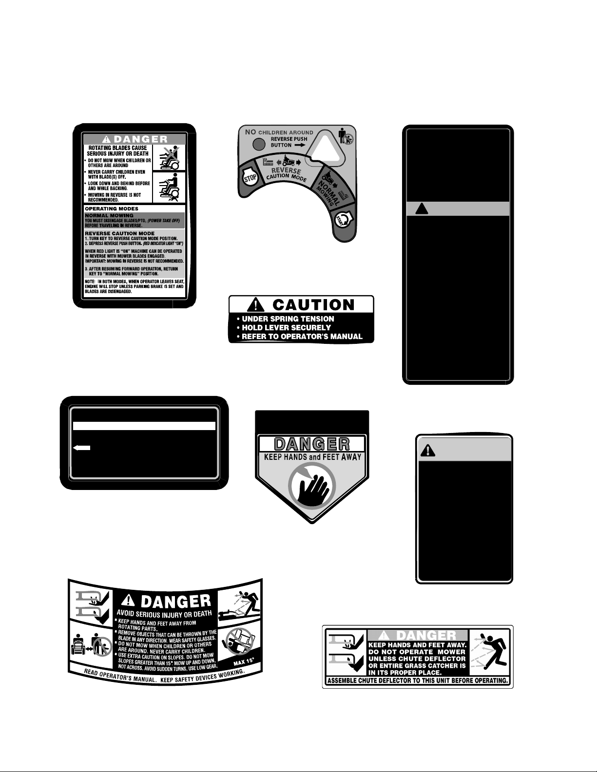
AVOID SERIOUS INJURY OR DEATH.
GO UP AND DOWN SLOPES, NOT ACROSS.
AVOID SUDDEN TURNS.
DO NOT OPERATE UNIT WHERE IT COULD
SLIP OR TIP.
IF MACHINE STOPS GOING UPHILL, STOP
PTO AND BACK DOWN HILL SLOWLY.
DO NOT MOW WHEN CHILDREN OR OTHERS
ARE AROUND.
NEVER CARRY CHILDREN EVEN WITH
BLADES OFF.
LOOK DOWN AND BEHIND BEFORE AND
WHILE BACKING.
KEEP SAFETY DEVICES [GUARDS, SHIELDS,
AND SWITCHES] IN PLACE AND WORKING.
REMOVE OBJECTS THAT COULD BE
THROWN BY THE BLADES.
KNOW LOCATION AND FUNCTION OF ALL
CONTROLS.
BE SURE THE BLADES AND THE ENGINE
ARE STOPPED BEFORE PLACING HANDS
OR FEET NEAR BLADES.
BEFORE LEAVING OPERATOR'S POSITION,
DISENGAGE PTO, ENGAGE BRAKE LOCK,
SHUT OFF ENGINE AND REMOVE KEY.
READ OPERATORS MANUAL
SAFETY GRAPHIC – LOCATED ON
LEFT SIDE OF MOWER DECK
GENERAL SAFETY INSTRUCTIONS
WARNING – LOCATED ON RIGHT
SIDE OF RUNNING BOARD
WAR NI NG
!
BE FAMILIAR WITH CONTROLS BEFORE
STARTING ENGINE AND OPERATING.
SET CHOKE, MOVE THROTTLE TO MID
POSITION AND DEPRESS BRAKE PEDAL.
TURN KEY TO THE START POSITION.
AFTER ENGINE STARTS OPEN CHOKE.
STOPPING INSTRUCTIONS
DISENGAGE PTO AND SET PARKING BRAKE
MOVE THROTTLE CONTROL TO MID
POSITION AND TURN KEY OFF.
STARTING INSTRUCTIONS
2.
3.
1.
2.
4.
1.
•
•
•
•
•
•
•
•
•
•
•
•
•
HANDS/FEET SAFETY
GRAPHIC - ON DECK
DEFLECTOR and SAFETY GRAPHIC –
LOCATED ON RIGHT SIDE OF DECK
SAFETY GRAPHIC – LOCATED
ON LEFT SIDE OF DECK
TO
REDUCE
THE
RISK
OF
INJURY,
DO
NOT
OPERATE
UNLESS
DISCHARGE
COVER
OR
GRASS
CATCHER
IS
IN
ITS
PROPER
PLACE.
IF
DAMAGED,
REPLACE
IMMED IATELY.
KEY SWITCH/MODULE GRAPHIC–
LOCATED ON DASH PANEL
DANGER GRAPHIC - REVERSE
CAUTION MODE – LOCATED ON
LEFT SIDE OF RUNNING BOARD
STEERING GEAR/ENGINE SCREEN
MAINTENANCE–ON LH ENGINE
SHIELD AT FRONT OF DASH PANEL
S
t
ee
r
i
n
g
B
o
x
A
cce
ss
P
a
n
e
l
• Rem o v e Wi n g Nu t On Lef t Panel To Grease St eeri ng Box Fitting.
•
Second Steering Box Fitting Can Be Accessed Below The Left Hand Frame Rail.
E
N
G
I
N
E
R
O
T
A
T
I
N
G
S
C
R
EE
N
Clean Debris From Engine Rotating Screen After Each Mowing.
Keep This Access Panel And Eng ine Screeen Free And Clear
Of Grass and Debris.
I
M
P
O
R
T
A
N
T
•
•
•
IMPORTANT
Perform These Maintenance Item With Engine Off.
TO ENSURE SAFE AND
PROPER OPERATION
O F TRANSMISSION,
ONLY USE CUB CADET
DRIVE SYSTEM
FLUID PLUS.
737-3120 - 1 QUART
737-3121 - 1 GALLON
READ
OPERATOR'S
MANUAL
WARNING
DEFLECTOR CHUTE
TRANSMISSION OIL GRAPHIC
ON REAR HITCH PLATE
PRODUCT GRAPHICS
Keep product safety graphics (decals) clean. Replace
any safety graphic that is damaged, destroyed, miss-
ing, painted over or can no longer be read. Replace-
ment safety graphics are available through your
dealer.
9
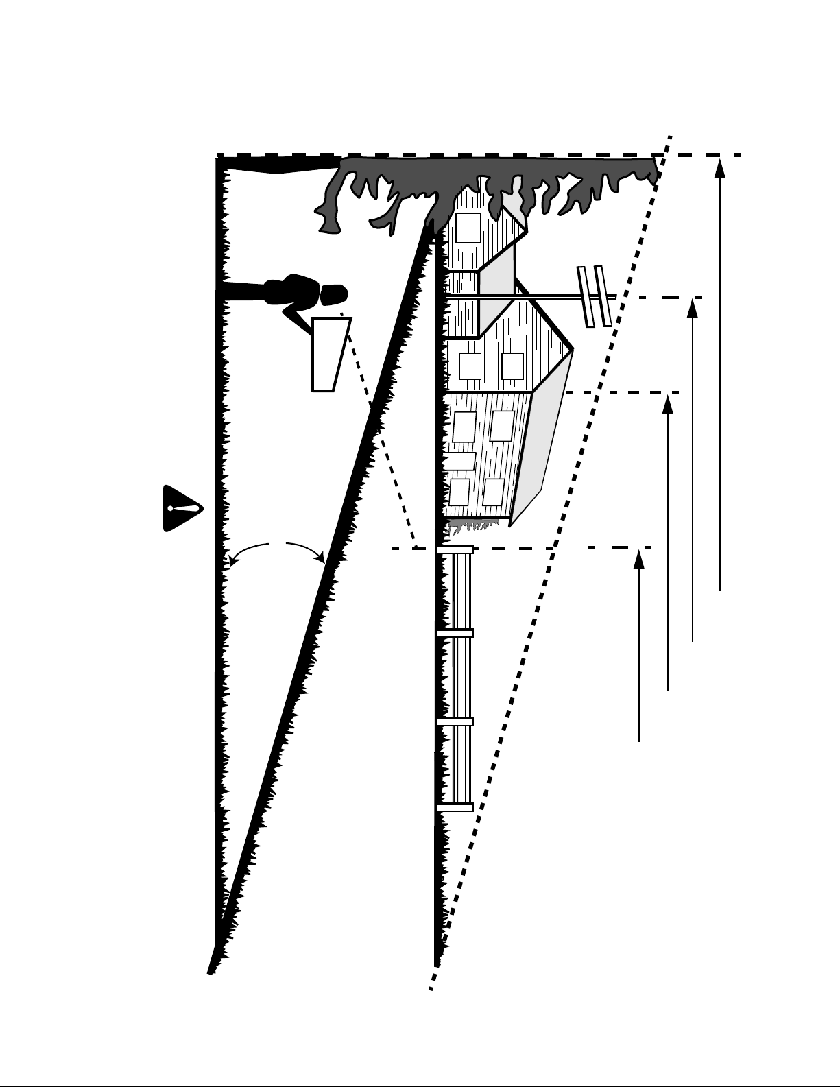
SLOPE GAUGE
15°
SIGHT AND HOLD THIS LEVEL WITH A VERTICAL TREE
A POWER POLE
A CORNER OF A BUILDING
OR A FENCE POST
F
O
L
D
O
N
D
O
T
T
E
D
L
I
N
E,
R
E
PR
E
S
E
N
T
I
N
G
A
1
5
°
SL
O
P
E
USE THIS PAGE AS A GUIDE TO DETERMINE SLOPES WHERE YOU MAY NOT OPERATE SAFELY.
WARNING
Do not mow on inclines with a slope in excess of 15 degrees (a rise of approximately 2-1/2 feet every 10 feet). A riding mower could
overturn and cause serious injury. If operating a walk-behind mower on such a slope, it is extremely difficult to maintain your footing
and you could slip, resulting in serious injury.
Operate RIDING mowers up and down slopes, never across the face of slopes.

10
www.cubcadet.com
CUB CADET LLC
P. O. BOX
361131
CLEVELAND, OH 44136
DEALER LOCATOR PHONE NUMBER:
877-282-8684
Model Number Serial Number
XXXXXXXXXXX XXXXXXXXXX
TO THE OWNER
This Operator’s Manual is an important part of your new tractor. The information contained in this manual has been
prepared in detail to help you better understand the features, correct operation, adjustments, and maintenance of
your tractor. The performance and dependability of this tractor rely greatly on the manner in which it is operated and
maintained. Therefore, it is recommended that all operators of the tractor carefully read this manual and fully under-
stand its operation. Keep the manual available for reference to assure proper operation, and also to ensure that
maintenance procedures are performed as scheduled to keep the tractor in optimal mechanical condition.
NOTE: All references to LEFT, RIGHT, FRONT, and REAR, unless specifically stated otherwise, indicate that rela-
tive position on the tractor when facing forward while seated in the operator’s seat.
CAUTION: DO NOT tow your hydrostatic tractor. Towing may damage the transmission. Place the tractor on a LEV-
EL SURFACE before pulling the transmission release lever to the disengaged position.
Your local authorized Cub Cadet dealer is interested in the performance of your tractor, and with the maintenance
needed to ensure its satisfactory operation. The dealer has trained service personnel familiar with the latest servic-
ing information, is equipped with the latest tools, and has a complete line of genuine Cub Cadet service parts which
assure proper fit and high quality.
CALLING SERVICE INFORMATION
The engine manufacturer is responsible for all engine-related issues with regards to performance, power-rating, and
specifications.
If you have difficulties with the tractor and/or equipment; have any questions regarding the operation or maintenance
of this equipment; or desire additional information not found in this manual, contact your nearest authorized Cub
Cadet dealer. If you need assistance in locating a dealer in your area, contact the Customer Dealer Referral Line by
calling:
1-877-282-8684
Or you may contact Cub Cadet via the internet by logging on to our Web Site at:
www.cubcadet.com
To obtain top performance and assure economical operation, the tractor should be inspected by your authorized
dealer periodically or at least once a year, depending on its hours of use. Before calling your dealer, make sure that
you have your model number(s) and manufacturing date available for the dealer.
RECORDING MODEL AND SERIAL NUMBER INFORMATION
Product identification plates are provided for major components of your tractor. The numbers on these plates are
important if your tractor should require dealer service, or if you need additional information on your tractor. Prior to
using your tractor for the first time, record the numbers from the identification plates in the appropriate spaces pro-
vided below.
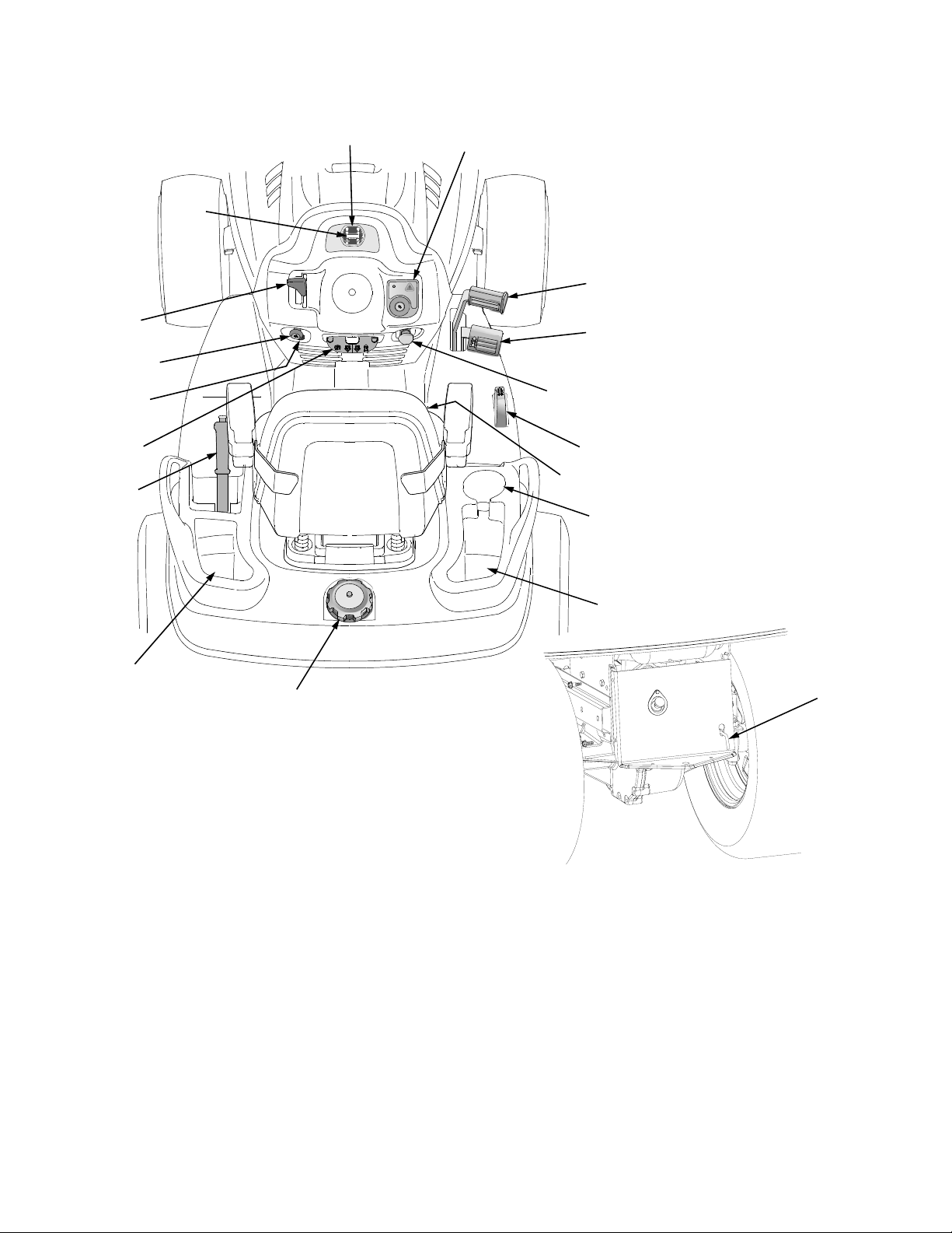
The chassis model plate, showing the factory model number and serial number (See Figure 3) can be found at the
front of the right hand frame channel just behind the right front wheel.
The engine serial number decal (See Figure 4) is located on the engine blower housing.
Hood Model Factory Model No. Mfg. Date
Delivery Date Engine Model/Spec. No. Engine Serial No.
Figure 3 Figure 4
11
SECTION I. KNOW YOUR TRACTOR
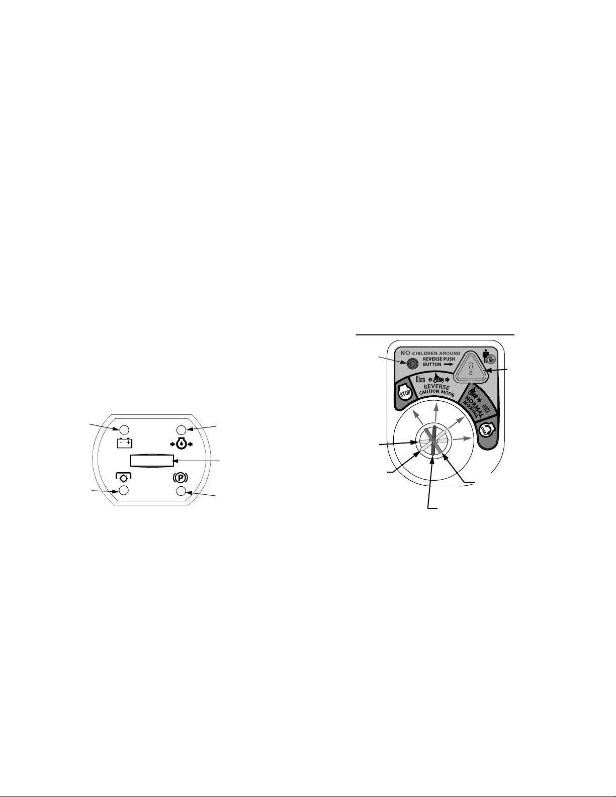
A. Hour Meter / Battery Display
B. Indicator Panel/Hour Meter
C. Key Switch Module
D. Power Take-Off (PTO) Control Switch
E. Throttle Control Lever
F. Choke Control
G. Parking Brake/Cruise Lever
H. Brake Pedal
I. Forward Control Pedal
J. Reverse Control Pedal
K. Seat Adjustment Lever
L. Lift Handle
M. 12V Power Outlet
N. Transmission Release Lever
O. Cup Holder
P. Fuel Fill Cap
Q. Storage Tray
Figure 5
B
A
D
F
E
H
G
C
I
J
K
L
N
M
Q
O
P
Q
12
A. HOUR METER/BATTERY DISPLAY
The hour meter records and digitally displays the
hours that the tractor has been operated (tenths of an
hour-right most digit).
NOTE: The hour meter is activated whenever the igni-
tion switch is turned to an ‘On’ position. Keep a record
of the actual hours of operation to assure all mainte-
nance procedures are completed according to the
instructions in this manual.
• When key is turned to the "ON" position, the
battery indicator light briefly illuminates and the
battery voltage is briefly displayed. The display
then changes to the accumulated hours.
• The hour meter display will also remind the
operator of maintenance intervals for changing
the engine oil. The LCD display will alternately
flash, “CHG” ; “OIL”; and the accumulated hours
for five minutes after every 50 hours of recorded
operation. The maintenance interval lasts for two
hours (from 50-52, 100-102, 150-152, etc.). The
LCD will flash as described for five minutes every
time the tractor’s engine is started during this
maintenance interval. Follow the oil change
intervals provided in this manual.
B. INDICATOR PANEL/HOUR METER
The indicator panel/hour meter uses indicator lights to
display the status of various functions of the tractor,
and also records the accumulated hours of operation.
Figure 6
Indicator Panel Features
Battery Indicator (Refer to Figure 6)
• Illuminates when the ignition switch it turned to an
ON position and the engine is not started.
• Illuminates to indicate the battery voltage has
dropped below 11.5 (+0.5/-1.0) DC volts (battery
voltage is also displayed on the hour meter). If
this indicator/display comes on during operation,
check the battery and charging system for possi-
ble causes and/or contact your Cub Cadet dealer.
Oil Pressure Indicator (Refer to Figure 6)
• This warning lamp indicates low engine oil pres-
sure. If this indicator illuminates, stop the tractor
immediately and check the engine oil level. If the
oil level is within the operating range, but the light
remains on, contact your Cub Cadet dealer.
NOTE: The oil pressure indicator may illuminate
when the key switch is turned to an on position,
but should turn off when the engine is started.
PTO Engaged Indicator (Refer to Figure 6)
• This indicator illuminates when the key switch is
turned to the "Start" position while the PTO switch
is in the "Engaged" position. Check this indicator
if the engine will not crank with the key switch in
the "Start" position. If necessary, move the PTO
switch to the "Disengaged" position.
Brake Engaged Indicator (Refer to Figure 6)
• This indicator illuminates when the key switch is
turned to the "Start" position and the brake pedal
is not fully depressed. Check this indicator if the
engine will not crank with the key switch in the
"Start" position. Fully depress the brake pedal.
C. KEY SWITCH MODULE
The key switch module consist of a four position key
switch, the “Reverse Push Button”, and a red indica-
tor light. See Figure 7.
Figure 7
The four key positions of key switch module (Refer to
Figure 7) and their functions are as follows:
• STOP — Stops the tractor engine and shuts
down the tractor’s electrical circuits.
• REVERSE CAUTION MODE — This position
allows the machine to be operated in reverse with
the blades (PTO) engaged.
• NORMAL MOWING — The normal operating
position. All safety interlock circuits are activated
and the blades (PTO) will disengage when the
tractor is driven in the reverse direction.
• START — Energizes the starter motor to crank
and start the tractor engine. Release the key as
soon as the engine starts and the key will return
to “NORMAL MOWING” position.
Battery
Oil
PTO
Parking Brake
Engaged
Engaged
Pressure
Indicator
Hour Meter/
Battery Display
Indicator
Indicator
Indicator
REVERSE
PUSH
INDICATOR
LIGHT
BUTTON
KEY IN REVERSE
CAUTION MODE
KEY IN NORMAL
MOWING MODE
KEY IN START
POSITION
KEY SWITCH MODULE
KEY IN STOP
POSITION
13
WARNING: To prevent accidental start-
ing and/or battery discharge, remove the
key from the key switch when the tractor
is not in use.
REVERSE PUSH BUTTON — The orange/triangular
button at the top/right corner of the key switch module
activates the system that allows the tractor’s blades
(PTO) to remain engaged when the tractor is driven in
the reverse direction. The key must be turned to the
“REVERSE CAUTION MODE” and the operator must
be in the tractor seat prior to depressing the button to
activate the system.
The RED INDICATOR LIGHT at the top/left corner of
the key switch module comes “ON” to alert the
operator that the key has been turned to the “Reverse
Caution Mode” position, the “Reverse Push Button”
has been depressed, and that the blades will remain
engaged when the machine is driven in reverse.
IMPORTANT: Mowing in reverse is not recommended.
D. POWER TAKE–OFF (PTO) CONTROL SWITCH
The power take-off (PTO) switch operates the front
electric PTO clutch. Pull the switch knob upward to en-
gage, or push downward to disengage the PTO clutch.
E. THROTTLE CONTROL LEVER
This lever controls the speed of the engine. When
set in a given position, the control cable will maintain
a uniform engine speed.
NOTE: When using PTO operated equipment, the
throttle lever must be in the “FAST” position.
F. CHOKE CONTROL
The choke control is operated manually. Pull the
knob out to choke the engine; push the knob in to
open the choke.
G. PARKING BRAKE /CRUISE CONTROL LEVER
The parking brake/cruise control lever is located in the
center of the dash panel below the steering wheel. This
is a single lever that is used to engage both the parking
brake and the cruise control feature.
To engage the parking brake, fully depress the brake
pedal and push downward on the parking brake/cruise
control lever. Hold the lever down while releasing the
brake pedal. The lever should lock in the down position
and the parking brake should be engaged.
NOTE: Always engage the parking brake when dis-
mounting the tractor.
To engage the cruise control, depress the forward con-
trol pedal to attain your desired speed; then push the
parking brake/cruise control lever downward. While
holding the lever down, release pressure from the drive
pedal. This will engage the cruise control and allow the
tractor to remain at approximately that same speed
while removing your foot from the forward drive pedal.
Refer to Section II- OPERATION for more instructions
regarding the cruise control
H. BRAKE PEDAL
The brake pedal is located at the front of the right run-
ning board above the forward control pedal. Press
down to stop the tractor and disengage the cruise con-
trol. The brake pedal must be fully depressed to acti-
vate the safety interlock switch when starting the
tractor.
I. FORWARD CONTROL PEDAL
The forward control pedal is located at the front of the
right running board below the brake pedal. Slowly
press down on the pedal to start moving forward. The
forward ground speed of the tractor is directly affected
by the distance the pedal is depressed.
J. REVERSE CONTROL PEDAL
WARNING: Always look down and
behind before and while backing. Do not
operate the tractor when children or
others are around. Stop the tractor
immediately if someone enters the area.
The reverse control pedal is located in the right front
running board rearward of the brake and forward con-
trol pedals. Press the pedal downward to move in re-
verse.
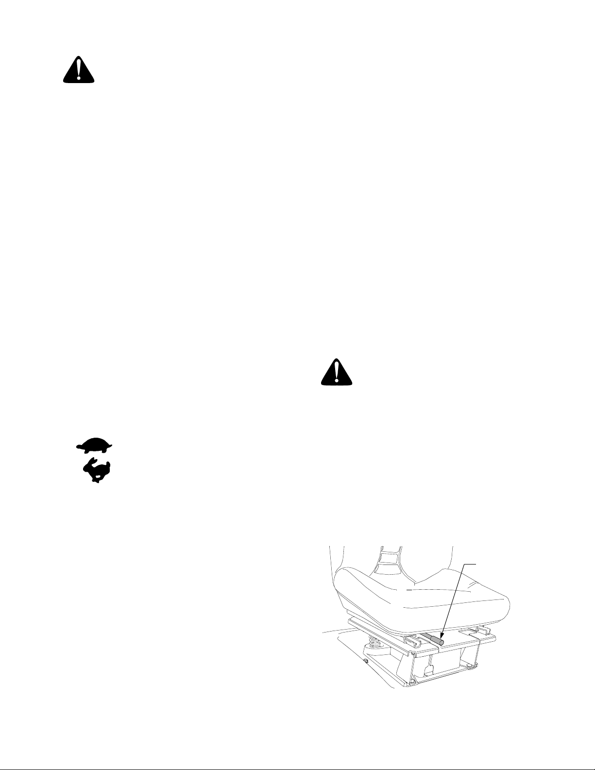
K. SEAT ADJUSTMENT LEVER
The seat adjustment lever (See Figure 8) is used to
move the seat forward or rearward to a comfortable op-
erating position. See ADJUSTING THE SEAT in Sec-
tion III.
Figure 8
SEAT
ADJUSTMENT
LEVER
This symbol shows slow position.
This symbol shows fast position.
14
L. LIFT HANDLE
The lift handle is located in the left fender and is used
to raise and lower equipment used with the tractor. The
equipment can be set in any of six positions by de-
pressing the top button on the handle, moving the han-
dle to the desired position, then releasing the button. It
may be necessary to push or pull slightly on the handle
to depress the button. A lift assist spring reduces the
effort needed to lift attachments. To adjust assist
spring tension refer to ADJUSTMENTS- Section III.
M. 12V POWER OUTLET
The 12V power outlet is located below the choke con-
trol on the left side of the dash panel. It is used for the
convenience of plugging in accessories that require a
power source with a maximum load of 5 amps at 12
volts.
N. TRANSMISSION RELEASE LEVER
The transmission release lever is located at the back of
the tractor in the rear drawbar. When engaged, this le-
ver opens a hydrostatic pump bypass valve, which al-
lows the tractor to be pushed short distances by hand.
To engage the release lever, lift and pull the lever rear-
ward through the keyhole until the flange on the rod is
outside the drawbar. Lower the lever into the slot and
release. To disengage the release lever, pull back on
the lever, lift out of the slot and release.
O. CUP HOLDER
The cup holder is located on the right fender.
P. FUEL FILL CAP
The fuel tank is located under the rear fender. The filler
cap is in the center/rear of the fender
Q. STORAGE TRAY
The storage trays are located near the rear of the seat
on each fender. Use the trays to carry small loose arti-
cles while operating the tractor.
FUSES
The two fuses are located under the hood behind the
dash panel. Fuses are installed to protect the tractor’s
electrical circuitry and components from damage
caused by excessive amperage.
SAFETY INTERLOCK SWITCHES
This tractor is equipped with a safety interlock system
for the protection of the operator. If the interlock sys-
tem should ever malfunction, do not operate the trac-
tor. Contact your authorized Cub Cadet Dealer. The
safety interlock system prevents the engine from
cranking or starting unless the brake pedal is fully de-
pressed, and the PTO switch is in the “OFF” position.
The safety interlock system will automatically shut off
the engine if the operator leaves the seat before en-
gaging the brake lock.
The safety interlock system will automatically shut off
the engine if the operator leaves the seat with the PTO
in the “RUN” position, regardless of whether the brake
lock is engaged. The PTO switch must be moved to the
“OFF” position to restart the engine.
With key switch in “NORMAL MOWING” position:
The safety interlock system will automatically shut off
the PTO if the reverse control pedal is depressed with
the PTO in the “RUN” position. To re-engage the PTO,
release the reverse control pedal, move the PTO
switch to the “OFF” position, then again pull the switch
to the “RUN” position.
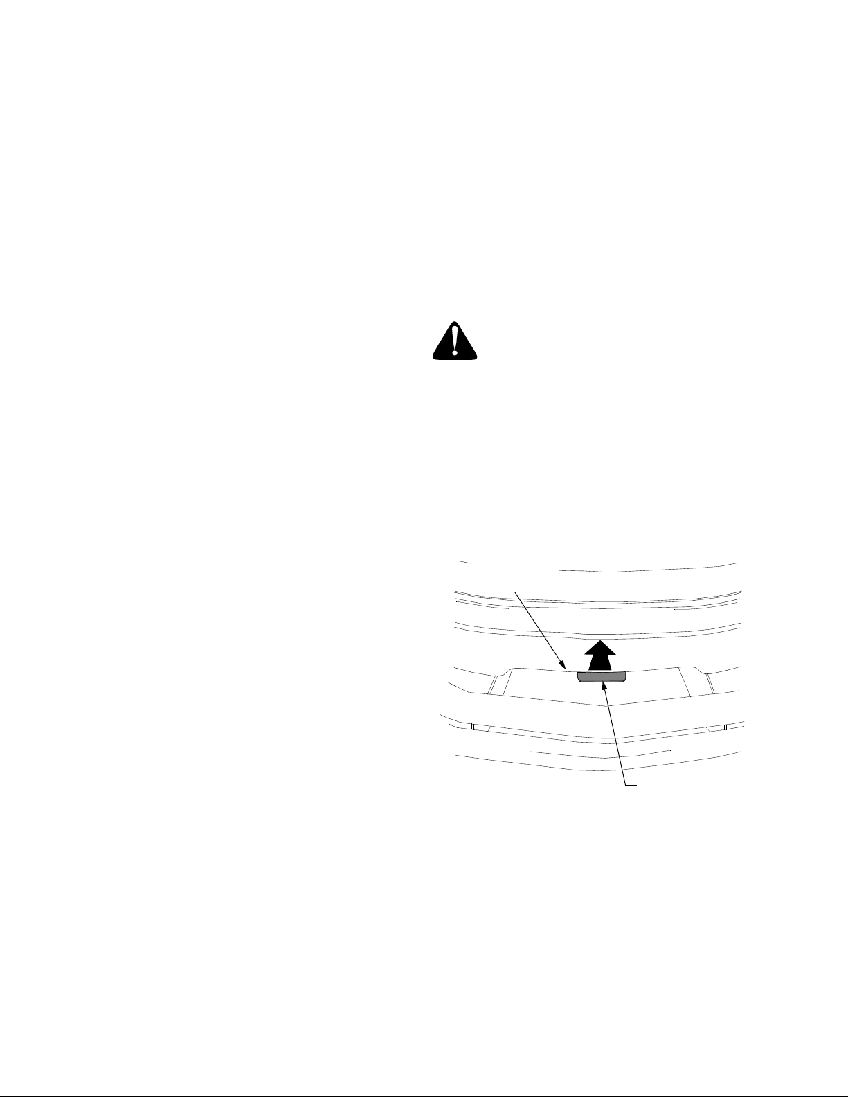
OPENING THE TRACTOR HOOD
WARNING: If the engine has been
recently run, the engine, muffler and
surrounding metal surfaces will be hot
and can cause burns to the skin. Allow
the tractor to cool and use caution when
opening the hood.
The hood of the tractor raises from the front of the trac-
tor and pivots upward toward the dash panel. The hood
is equipped with gas cylinders to aid in lifting the hood
and to hold the hood in the up position.
To raise the hood proceed as follows:
• Locate the latch bracket at the bottom/center of
the front of the hood. See Figure 9.
Figure 9
• Pull the latch bracket upward until it releases from
the latch rod; then lift the hood.
To close the hood, push the hood firmly downward
until the latch bracket engages the latch rod.
NOTE: To ensure the hood is locked in the down
position, push the latch bracket fully downward after
closing the hood.
NOTE: Some front mounted attachments must be fully
lowered to allow the hood to be opened. Use care to
avoid damage to the hood.
Pull Upward
Latch Bracket
Front/Bottom
of Hood

15
SECTION II. OPERATION
WARNING: Before you operate the trac-
tor, study this manual carefully.
Familiarize yourself with the operations
of all the instruments and controls.
Learn to operate this machine safely.
Don’t risk INJURY or DEATH.
1. Before starting the engine, the operator must be
seated, the PTO switch must be in the “OFF” posi-
tion and the brake pedal must be fully depressed.
2. Keep all shields in place. Keep away from moving
parts.
3. NO RIDERS! Keep all people a safe distance
away. Look down and behind to both sides before
and while backing up.
4. DO NOT direct the mower discharge at people.
5. Avoid slopes. Tractors can roll over.
6. Before leaving the operator’s seat: Shut off the
PTO, engage the parking brake, shut off the
engine and remove the ignition key. Wait for all
movement to stop before servicing or cleaning.
7. Do not fill the fuel tank when the engine is running
or while the engine is hot. Tighten the fuel cap
securely.
BEFORE STARTING YOUR TRACTOR
1. Read and understand this entire manual.
WARNING: Gasoline is extremely
flammable and it vapors can explode if
ignited. Store gasoline only in approved
containers, in well ventilated, unoccupied
buildings, away from sparks or flames.
Do not fill the fuel tank while the engine
is hot or running, since spilled fuel could
ignite if it comes in contact with hot parts
or sparks from ignition. Do not start the
engine near spilled fuel. Never use
gasoline as a cleaning agent.
2. This engine is certified to operate on unleaded
gasoline. For best results, fill the fuel tank with
only clean, fresh, unleaded gasoline with a pump
sticker octane rating of 87 or higher. In countries
using the Research method, it should be 90
octane minimum.
Unleaded gasoline is recommended because it
leaves less combustion chamber deposits and re-
duces harmful exhaust emissions. Leaded gaso-
line is not recommended and must not be used
where exhaust emissions are regulated.
NOTE: Purchase gasoline in small quantities. Do not
use gasoline left over from the previous season, to
minimize gum deposits in the fuel system.
Gasohol (up to 10% ethyl alcohol, 90% unleaded
gasoline by volume) is an approved fuel. Other
gasoline/alcohol blends are not approved.
Methyl Tertiary Butyl Ether (MTBE) and unleaded
gasoline blends (up to a maximum of 15% MTBE
by volume) are approved fuels. Other gasoline/
ether blends are not approved.
3. Check the engine and transmission oil levels.
4. Clean the air cleaner element if necessary.
5. Check the tire inflation pressures.
6. Adjust the seat for operator’s maximum comfort,
visibility, and for maintaining complete control of
the tractor.
SAFETY INTERLOCK SYSTEM
WARNING: This unit is equipped with a
safety interlock system designed for the
protection of the operator. Do not
operate the tractor if any part of the
interlock system is malfunctioning.
Periodically check the functions of the
interlock system for proper operation as
described below:
• The safety interlock system prevents the en-
gine from cranking or starting unless the brake
pedal is fully depressed and the PTO clutch en-
gagement switch is in the “OFF” position.
• The safety interlock system will automatically
shut off the engine if the operator leaves the
seat before engaging the brake pedal lock.
• The safety interlock system will automatically
shut off the engine if the operator leaves the
seat with the PTO engaged, regardless of
whether the brake pedal lock is engaged.
• With key switch in “NORMAL MOWING”
position: The safety interlock system will
automatically disengage the PTO if the reverse
control pedal is pressed down with the PTO in
the “RUN” position. To re-engage the PTO,
release the reverse control pedal, push the
PTO switch down to the “OFF” position, and
then pull the PTO switch upward to engage the
PTO.

16
STARTING THE ENGINE
WARNING: For personal safety, the
operator must be sitting in the tractor
seat when starting the engine. Never try
to start the engine while standing on the
ground.
1. Operator must be sitting in the tractor seat.
2. Pull choke control knob to full choke position.
Less choking may be necessary due to variations
in temperature, grade of fuel, etc. Little or no
choking will be needed when the engine is warm.
3. Place the throttle midway between the “SLOW”
and “FAST” position.
4. Place the PTO switch in the “OFF” position.
5. Fully depress the brake pedal.
6. Turn the ignition key clockwise to the “START”
position and release it as soon as the engine
starts. However, do not crank the engine
continuously for more than 10 seconds at a time.
If the engine does not start, allow a 60 second
cool down period between starting attempts.
Failure to follow these guidelines can burn out, or
permanently damage, the starter motor.
NOTE: If the engine develops sufficient speed to dis-
engage the starter but does not keep running, allow the
engine to come to a complete stop before attempting
to restart the engine. If the starter is engaged while the
flywheel is rotating, the starter pinion and the flywheel
ring gear may clash resulting in damage to the starter.
IMPORTANT: If the starter does not turn the engine
over, shut off starter immediately. Do not make further
attempts. Contact your Cub Cadet dealer.
7. After the engine starts, slowly release the brake
pedal. As the engine warms up, gradually push
the choke control knob all the way in. Do not use
the choke to enrich the fuel mixture, except as
necessary to start the engine.
NOTE: Upon start-up, a metallic ticking may occur.
This is caused by hydraulic lifter leakdown. Run the en-
gine for 5 minutes. The noise will normally cease in the
first minute. If noise continues, run the engine at mid-
throttle for 20 minutes. If the noise persists, contact
your Cub Cadet dealer.
COLD WEATHER STARTING HINTS
WARNING: Engine exhaust gases are
dangerous. Do not run the engine in a
confined area such as a storage building
any longer than is necessary. Immedi-
ately move the tractor outdoors.
1. When starting the engine at temperatures near or
below freezing, ensure the correct viscosity motor
oil is used in the engine and the battery is fully
charged.
2. Disengage all possible external loads.
3. Be sure the battery is in good condition. A warm
battery has much more starting capacity than a
cold battery.
4. Use fresh winter grade fuel. Winter grade
gasoline has higher volatility to improve starting.
Do not use gasoline left over from summer.
5. Follow the previous instruction for STARTING
THE ENGINE.
STOPPING THE ENGINE
WARNING: Remove the key from the
ignition switch to prevent accidental
starting or battery discharge if the
equipment is left unattended.
Place the PTO switch in the “OFF” position. Move the
throttle control lever between the “MID” and “FAST”
positions. Wait a moment to allow the engine speed to
stabilize, then turn the ignition key to the “STOP” posi-
tion. Remove the key from the ignition switch.
TRACTOR BREAK-IN PROCEDURE
IMPORTANT: Never operate a new engine immedi-
ately under full load. Break it in carefully as shown in
the table below.
Period
Engine Throttle
Control Lever
Position Load
1/2 3/4 Full
1st hour X None
2nd hour
X
X
Light drawbar load
or
Mowing with tractor
at slow groundspeed
3rd through
12th hour
X
X
Medium drawbar
load
or
Normal mowing

17
DRIVING THE TRACTOR
NOTE: Avoid sudden starts, excessive speed and sud-
den stops.
WARNING: Do not leave the seat of the
tractor without disengaging the PTO and
engaging the parking brake. If leaving the
tractor unattended, turn the ignition key
off and remove the key.
IMPORTANT: When using PTO driven equipment, the
throttle lever should be in the “FAST” position.
• Depress the brake pedal to release the parking
brake and let the pedal up. Move the throttle lever
to the position where the engine operates best for
the load to be handled (usually full throttle).
Driving With Forward Or Reverse Pedals.
WARNING: Do not use the forward or
reverse control pedals to change the
direction of travel when the tractor is in
motion. Use the brake pedal to bring the
tractor to a stop before changing
direction with either the forward or
reverse control pedal.
1. To move in the forward direction, slowly depress
the forward control pedal until the desired speed is
achieved.
2. To move in the reverse direction, check that the
area behind is clear then fully depress the reverse
control pedal. Always look down and behind
before and while backing up.
Using The Cruise Control Feature.
IMPORTANT: The cruise control feature can only be
operated in the forward direction.
1. Slowly depress the forward control pedal until the
desired speed is achieved.
2. Lightly push the parking brake/cruise control
lever downward as far as possible and hold in this
position.
3. While continuing to hold the parking brake/cruise
control lever down, lift your foot from the forward
control pedal (you should feel the cruise latch
engage).
4. If properly engaged, the cruise lever and forward
control pedal should lock in the down position,
and the tractor will maintain the approximate
same forward speed.
5. Disengage the cruise control using one of the
following methods:
• Depress the brake pedal to disengage the cruise
control and stop the tractor.
• Lightly depress the forward control pedal.
• To change to the reverse direction when operat-
ing with cruise control, depress the brake pedal to
disengage the cruise control and stop the tractor;
then depress the reverse control pedal.
DRIVING ON SLOPES
Refer to the SLOPE GAUGE on page 9 to help deter-
mine slopes where you may not operate safely.
WARNING: Do not mow on inclines with
a slope in excess of 15 degrees (a rise of
approximately 2-1/2 feet every 10 feet).
The tractor could overturn and cause
serious injury.
WARNING: Operate the tractor up and
down slopes, never across slopes. Do
not drive so that the tractor may tip over
sideways .
Before operating the tractor on any slope, walk the
slope to look for possible hazards such as rocks.
mounds, ruts, stumps or other surface irregularities
which could cause the tractor to overturn.
Back the tractor with implement up the steepest portion
of each slope you intend to work. If the tractor cannot
negotiate the slope in reverse, the slope is too steep to
be worked.
Avoid turns when driving on a slope. If a turn must be
made, turn down the slope. Turning up a slope greatly
increases the chance of a roll over.
Avoid stopping when driving up a slope. If it is neces-
sary to stop while driving up a slope, start up smoothly
and carefully to reduce the possibility of flipping the
tractor over backward.
WARNING: The hydrostatic transmis-
sion will not hold the tractor on a hill.
Normal internal leakage in the transmis-
sion will allow the tractor to roll
downhill. To avoid an accident and/or
possible injury, engage the brake pedal
lock.
 Loading...