


 Loading...
Professional Shop Manual
2000 Series Tractors
(2011 Model year and Newer)
NOTE: These materials are for use by trained technicians who are experienced in the service and repair of outdoor power equipment of the kind described in this publication, and are not intended for use by untrained or inexperienced individuals. These materials are intended to provide supplemental information to assist the trained technician. Untrained or inexperienced individuals should seek the assistance of an experienced and trained professional. Read, understand, and follow all instructions and use common sense when working on power equipment. This includes the contents of the product’s Operators Manual, supplied with the equipment. No liability can be accepted for any inaccuracies or omission in this publication, although care has been taken to make it as complete and accurate as possible at the time of publication. However, due to the variety of outdoor power equipment and continuing product changes that occur over time, updates will be made to these instructions from time to time. Therefore, it may be necessary to obtain the latest materials before servicing or repairing a product. The company reserves the right to make changes at any time to this publication without prior notice and without incurring an obligation to make such changes to previously published versions. Instructions, photographs and illustrations used in this publication are for reference use only and may not depict actual model and component parts.
© Copyright 2011 MTD Products Inc. All Rights Reserved
MTD Products Inc. - Product Training and Education Department
Table of Contents
Chapter 1: Introduction |
|
Professional shop manual intent ........................................................................ |
1 |
Fasteners ........................................................................................................... |
1 |
Assembly ........................................................................................................... |
3 |
Description of the 2000 series tractor ................................................................ |
3 |
Model and Serial Numbers ................................................................................ |
4 |
Chapter 2: Engine Related Parts |
|
Muffler ................................................................................................................ |
5 |
Fuel tank removal/replacement .......................................................................... |
6 |
Throttle cable adjustment ................................................................................. |
10 |
Choke cable adjustment .................................................................................. |
10 |
Choke and Throttle levers and cables ............................................................. |
11 |
Engine removal/installation .............................................................................. |
13 |
Chapter 3: Brakes |
|
Brake adjustment ............................................................................................. |
17 |
Brake puck/rotor replacement .......................................................................... |
19 |
Brake shaft assembly ....................................................................................... |
21 |
Brake rod adjustment 2....................................................................................... |
3 |
Chapter 4: Body |
|
What is covered by this chapter ....................................................................... |
25 |
Hood ................................................................................................................ |
25 |
Hood components: side vent removal .............................................................. |
26 |
Hood components: Headlight removal ............................................................. |
27 |
Hood components: grille removal .................................................................... |
28 |
Hood components: pivot bracket removal ........................................................ |
30 |
Fender and running board ............................................................................... |
31 |
Dash Panel ...................................................................................................... |
35 |
Chapter 5: Drive system |
|
Transmission fluid filter .................................................................................... |
39 |
Transmission fluid change ............................................................................... |
40 |
Drive shaft ........................................................................................................ |
41 |
Hydro neutral control adjustment ..................................................................... |
42 |
Transmission removal/replacement ................................................................. |
44 |
Forward drive pedal shaft ................................................................................ |
48 |
Reverse drive pedal shaft ................................................................................ |
50 |
Transmission Disassembly .............................................................................. |
52 |
Transmission Assembly ................................................................................... |
61 |
I
Chapter 6A: Manual Steering |
|
Steering alignment ........................................................................................... |
67 |
Front wheels .................................................................................................... |
69 |
Front wheel bearings ....................................................................................... |
70 |
Axles ................................................................................................................ |
71 |
Steering sector gear and steering pinion gear ................................................. |
72 |
Steering shaft ................................................................................................... |
74 |
Pivot bar ........................................................................................................... |
78 |
Steering housing .............................................................................................. |
79 |
Greasing the steering housing ......................................................................... |
80 |
Chapter 6B: Electronic Power Steering |
|
Rubber Torsion Coupling ................................................................................. |
81 |
EPS Module ..................................................................................................... |
81 |
EPS motor & gearbox ...................................................................................... |
82 |
Troubleshooting the EPS ................................................................................. |
83 |
EPS removal/replacement ............................................................................... |
88 |
Chapter 7: electrical system |
|
Introduction ...................................................................................................... |
93 |
RMC Module .................................................................................................... |
93 |
Key switch ........................................................................................................ |
94 |
RMC Module .................................................................................................... |
96 |
To identify a faulty RMC module: ..................................................................... |
97 |
PTO Switch ...................................................................................................... |
99 |
Brake Switch .................................................................................................... |
99 |
Reverse Safety Switch ................................................................................... |
100 |
Seat Safety Switch ......................................................................................... |
100 |
Seat circuit (GTX2154LE) .............................................................................. |
101 |
Starter solenoid .............................................................................................. |
102 |
PTO Relay ..................................................................................................... |
102 |
Start Circuit .................................................................................................... |
103 |
Run Circuit ..................................................................................................... |
106 |
Run Circuit / Reverse Caution mode ............................................................. |
107 |
Engine shut-down circuits .............................................................................. |
108 |
Charging circuit .............................................................................................. |
109 |
PTO Circuit .................................................................................................... |
114 |
Reverse Mower Control (RMC) circuit operation ........................................... |
116 |
Deck lift circuit ................................................................................................ |
118 |
Electrical diagnosis ........................................................................................ |
119 |
Electronics ..................................................................................................... |
119 |
Electrical environment: AC Vs. DC ................................................................ |
120 |
Ohm’s Law ..................................................................................................... |
121 |
Kirchhoff’s current law .................................................................................... |
121 |
Kirchhoff’s voltage law ................................................................................... |
122 |
How the system is wired together .................................................................. |
122 |
Types of circuits ............................................................................................. |
123 |
Series ............................................................................................................. |
123 |
II
Parallel ........................................................................................................... |
123 |
Series/parallel ................................................................................................ |
124 |
Shorts ............................................................................................................. |
124 |
Opens ............................................................................................................ |
124 |
Increased resistance ...................................................................................... |
124 |
The Tools ....................................................................................................... |
125 |
Digital Multi-meter .......................................................................................... |
126 |
Wiring diagram or schematic ......................................................................... |
127 |
Fused jumper wires ........................................................................................ |
127 |
Test lights ....................................................................................................... |
127 |
Self-powered continuity lights ........................................................................ |
127 |
Ammeters and specialized charging system testers ...................................... |
128 |
Batteries ......................................................................................................... |
129 |
Charging the battery ...................................................................................... |
129 |
Checking battery condition ............................................................................. |
130 |
Battery Testers ............................................................................................... |
131 |
Adjustable load testers ................................................................................... |
131 |
Fixed load testers ........................................................................................... |
132 |
Conductance testers ...................................................................................... |
132 |
Battery discharge test .................................................................................... |
133 |
Storage of batteries ........................................................................................ |
133 |
Electrical Troubleshooting .............................................................................. |
134 |
Voltage Drop Test .......................................................................................... |
136 |
Testing switches ............................................................................................ |
139 |
Diodes ............................................................................................................ |
140 |
Relay.............................................................................................................. |
142 |
Schematics .................................................................................................... |
143 |
Chapter 8: Decks and lift systems |
|
Cutting decks ................................................................................................. |
147 |
Deck removal/installation ............................................................................... |
147 |
Cleaning the deck .......................................................................................... |
149 |
Blades ............................................................................................................ |
150 |
PTO belt ......................................................................................................... |
152 |
Deck Belt ........................................................................................................ |
154 |
Deck Belt Routings ........................................................................................ |
155 |
Spindle pulleys and spindle shafts ................................................................. |
158 |
Spindle removal/installation ........................................................................... |
159 |
Spindle overhaul ............................................................................................ |
160 |
Leveling the deck ........................................................................................... |
162 |
Deck Gauge Wheel Adjustment ..................................................................... |
164 |
Deck lift shaft bushings .................................................................................. |
165 |
Deck lift shaft assembly (manual) .................................................................. |
166 |
Deck lift shaft assembly (electric) .................................................................. |
169 |
Deck lift actuator (electric lift)......................................................................... |
172 |
Electric PTO clutch ........................................................................................ |
174 |
Evaluating the PTO clutch ............................................................................. |
176 |
III
Chapter 9: Maintenance intervals |
|
Lubrication ..................................................................................................... |
179 |
Engine maintenance ....................................................................................... |
179 |
The spark plugs ............................................................................................. |
180 |
Air filter and pre-cleaner................................................................................. |
181 |
Oil change ...................................................................................................... |
183 |
Oil filter........................................................................................................... |
184 |
Fuel system.................................................................................................... |
184 |
Servicing the fuel system ............................................................................... |
185 |
Fuel filter ........................................................................................................ |
185 |
Clean the engine............................................................................................ |
186 |
IV

Introduction
CHAPTER 1: INTRODUCTION
Professional Shop Manual intent
This Manual is intended to provide service dealers with an introduction to the electrical and mechanical aspects of the 2000 series tractor.
•Detailed service information about the engine will be provided by the engine manufacturer.
Disclaimer: The information contained in this manual is correct at the time of writing. Both the product and the information about the product are subject to change without notice.
About the text format:
NOTE: is used to point out information that is relevant to the procedure, but does not fit as a step in the procedure.
•Bullet points: indicate sub-steps or points.
|
|
|
|
|
|
|
|
|
|
Caution is used to point out potential danger to the technician, operator, bystanders, or sur- |
|
|
|
! CAUTION |
|
||
|
|
|
rounding property. |
|
|
|
|
|
|
|
|
|
|
|
|
|
|
|
|
|
|
|
|
|
|
|
|
|
|
|
|
|
|
Warning indicates a potentially hazardous situation that, if not avoided, could result in death of |
|
|
|
! WARNING |
|
||
|
|
|
serious injury. |
|
|
|
|
|
|
|
|
|
|
|
|
|
|
|
|
|
|
|
|
|
|
|
|
|
|
|
|
|
|
Danger indicates an imminently hazardous situation that, if not avoided, will result in death or |
|
|
|
! DANGER |
|
||
|
|
|
serious injury. This signal word is to be limited to the most extreme situations |
|
|
|
|
|
|
|
|
|
|
|
|
|
|
Disclaimer: This manual is intended for use by trained, professional technicians.
•Common sense in operation and safety is assumed.
•In no event shall MTD or Cub Cadet be liable for poor text interpretation or poor execution of the procedures described in the text.
•If the person using this manual is uncomfortable with any procedures they encounter, they should seek the help of a qualified technician or Cub Cadet Technical Support.
Fasteners
•Most of the fasteners used on these mowers are sized in fractional inches. The engine and transmissions are metric. For this reason, wrench sizes are frequently identified in the text, and measurements are given in U.S. and metric scales.
•If a fastener has a locking feature that has worn, replace the fastener or apply a small amount of releasable thread locking compound such as Loctite® 242 (blue).
•Some fasteners like cotter pins are single-use items that are not to be reused. Other fasteners such as lock washers, retaining rings, and internal cotter pins (hairpin clips) may be reused if they do not show signs of wear or damage. This manual leaves that decision to the judgement of the technician.
1

2000 Series Tractors
|
|
|
• |
Be prepared in case of emergency: |
|
|
! CAUTION |
|
|||
|
|
|
Keep a fire extinguisher nearby |
|
|
|
|
|
|
Keep a first aid kit nearby |
|
|
|
|
|
Keep emergency contact numbers handy |
|
|
|
|
• |
Replace any missing or damaged safety labels on shop equipment. |
|
|
|
|
• |
Replace any missing or damaged safety labels on equipment being serviced. |
|
|
|
|
|
|
|
|
|
|
|
|
|
|
|
|
• |
Grooming and attire: |
|
|
! WARNING |
|
|
Do not wear loose fitting clothing that may become entangled in equipment. |
|
|
|
|
|
Long hair should be secured to prevent entanglement in equipment. |
|
|
|
|
|
||
|
|
|
|
Jewelry is best removed. |
|
|
|
|
• |
Protective gear: includes, but is not limited to |
|
|
|
|
|
Clear eye protection ................................ |
while working around any machinery |
|
|
|
|
Protective gloves ..................................... |
where necessary |
|
|
|
|
Armored footwear .................................... |
when working around any machinery |
|
|
|
|
Hearing protection ................................... |
in noisy environments |
|
|
|
|
Chemically resistant gloves ..................... |
when working with chemicals or solvents |
|
|
|
|
Respirator ................................................ |
when working with chemical or solvents |
|
|
|
|
Appropriate tinted eye protection............. |
when cutting or welding |
|
|
|
|
Flame resistant headgear, jacket, chaps . when cutting or welding |
|
|
|
|
|
|
|
•Remember that some hazards have a cumulative effect. A single exposure may
! CAUTION |
cause little or no harm, but continual or repeated exposure may cause very serious |
harm. |
•Clean spills and fix obviously dangerous conditions as soon as they are noticed.
•Lift and support heavy objects safely and securely.
•Be aware of your surroundings and potential hazards that are inherent to all power equipment. All the labels in the world cannot protect a technician from an instant of carelessness.
! DANGER
•Exhaust fumes from running engines contain carbon monoxide (CO). Carbon monoxide is a colorless odorless gas that is fatal if inhaled in sufficient quantity. Only run engines in well ventilated areas. If running engines indoors, use an exhaust evacuation system with adequate make-up air ventilated into the shop.
2

Introduction
Assembly
Torque specifications may be noted in the part of the text that covers assembly, they may also be summarized in tables along with special instructions regarding thread locking or lubrication. Whichever method is more appropriate will be used. In many cases, both will be used so that the manual is handy as a quick-reference guide as well as a step-by-step procedure guide that does not require the user to hunt for information.
The level of assembly instructions provided will be determined by the complexity and of reassembly, and by the potential for unsafe conditions to arise from mistakes made in assembly.
Some instructions may refer to other parts of the manual for subsidiary procedures. This avoids repeating the same procedure two or three times in the manual.
Description of the 2000 series tractor
The Cub Cadet 2000 series tractor has been substantially up-dated for the 2011 season. These tractors feature:
• Kohler Command horizontal shaft engines.
• A drive shaft that transfers power efficiently to the transmission without the need for belts.
• Cast-iron transmission and front axle.
• 12 gauge steel ladder frame.
• Electric PTO Clutch.
• Manual and electric deck lift systems are available.
• Adjustable tilt steering column (available on most models.
Figure 1.1
The 50th Anniversary model also features:
• Electronic Power Steering.
• Electric deck lift is standard.
• 54” fabricated deck.
• A special 2-tone painted hood.
• A custom front bumper.
Figure 1.2
3

2000 Series Tractors
Model and Serial Numbers |
|
|
|
|
The model and serial number tag can be found |
|
|
|
|
under the seat. See Figure 1.3. |
Model number |
Serial number |
||
The serial number is located to the right of the model |
||||
|
||||
|
|
|
||
number as shown above. See Figure 1.3. |
|
|
|
|
|
|
|
||
|
Figure 1.3 |
The model number is 14W-3AE-010. The break down of what the number mean is as follows: |
|
14 ........................................ |
Garden tractor |
.......W. ................................. |
Sales revision |
...........-. ............................... |
Marketing revision |
.............3. ............................ |
Frame |
.................A......................... |
Engine (A = Kohler twin 23 hp) |
....................E...................... |
Deck lift (E = electric) |
.........................- .................. |
Deck (The 50th anniversary model is the only version that comes equipped with a deck) |
.............................010 ......... |
Customer number |
The serial number is 1C281B20053. The serial number reads as follows: |
|
1 .............................................................................................. |
Engineering level |
..C............................................................................................ |
Month of production (C=March) |
.....28 ....................................................................................... |
Day of the month |
.........1 ..................................................................................... |
Last digit of the year |
...........B................................................................................... |
Plant it was built in (Willard, OH) |
..............2 ................................................................................ |
Assembly line number |
.................0053 ....................................................................... |
Number of unit built |
4
Engine Related Parts
CHAPTER 2: ENGINE RELATED PARTS
This chapter covers the engine accessories that are manufactured by Cub Cadet.
IMPORTANT: The engine is manufactured by Kohler. Refer to the Kohler manual for engine specific service information.
Muffler
Conduit clamp
Heat shield screws
Figure 2.1
Exhaust pipe
Figure 2.2
To Remove/replace the muffler:
1.Remove the hood by following the procedures described in Chapter 4: Body.
2.Remove the screw that holds the conduit clamp to the heat shield using a 1/2” wrench. See Figure 2.1.
3.Remove the four screws (two on each side) that hold the heat shield to the engine using a 5/16” wrench.
4.Slide the heat shield off of the engine.
5.Remove the two nuts that hold each exhaust pipe to the cylinder head using a 1/2” wrench.
See Figure 2.2.
6.Remove the muffler and exhaust pipes.
NOTE: The exhaust pipes are welded to the muffler. The pipes and the muffler are serviced as one assembly.
7.Clean and remove all gasket material from the cylinder head (and the exhaust pipes if they are being reused).
8.Using new gaskets, install the muffler by following the previous steps in reverse order.
NOTE: Tighten the exhaust nuts to a torque of 246 in lbs (27.8 Nm).
9.Test drive the mower in a safe area before returning it to service.
5

2000 Series Tractors
Fuel tank removal/replacement
Remove/replace the fuel tank by following these steps:
|
|
|
|
|
|
|
|
|
Gasoline and its vapors are extremely flammable. Use common sense when working around |
|
|
|
|
! CAUTION |
|||
|
|
the fuel system |
|
|
|
|
|
|
|
|
|
|
|
|
|
|
|
|
|
|
|
|
|
1. |
Safely drain the gasoline from the fuel tank. |
|
|
||
2. |
Disconnect the seat switch. See Figure 2.3. |
|
|
||
|
|
NOTE: On the GTX2154LE, it will be necessary to |
|
|
|
|
|
cut the wire tie that holds the seat switch |
|
|
|
|
|
connector to the seat frame. |
|
|
|
|
|
NOTE: When reconnecting the seat switch plug on |
|
|
|
|
|
the GTX2154LE, it must be wire tied back |
|
|
|
|
|
together and attached to the seat frame. |
|
|
|
|
|
Failure to do this can cause the connector to |
|
|
|
|
|
get caught in the seat bracket and rip the |
|
|
|
|
|
wires out of the seat. If this happens, the |
|
|
|
|
|
tractor will shut down when the brake is |
|
|
|
|
|
released and the whole seat must be |
|
|
|
|
|
replaced. |
|
|
|
3. |
Push the barbed fastener on the seat switch har- |
Figure 2.3 |
|||
|
|
||||
ness out of the hole in the fender.
4.Remove the four socket headed cap screws that hold the seat tracks to the fender using a T-40 torx driver. See Figure 2.4.
Figure 2.4
6

Engine Related Parts
NOTE: On the GTX2154LE:
•Remove the four screws, indicated by the arrows in Figure 2.5, that hold the seat frame to the fender using a 7/16” wrench.
•Remove the two screws that hold the rear of the fender to the frame using a 7/16” wrench.
Figure 2.5
On manual deck lift models:
5.Remove the deck lift lever grip. See Figure 2.6.
NOTE: A blow-gun with air pressure regulated to less than
Grip 25 PSI (1.72 Bars), may be inserted into the small hole at the end of a rubber grip to inflate it slightly,
easing removal.
Figure 2.6
On electric deck lift models:
6.Remove the screw that holds the deck cutting height lever to the shaft using a T40 torx driver.
7.Pull the cutting height lever off of the shaft.
8.Disconnect the deck lift switch.
Screw
Figure 2.7
7

2000 Series Tractors
9.Unthread the fuel cap.
10.Pull the fuel cap tether retainer out of the fuel tank using a long pair of pliers. See Figure 2.8.
NOTE: The fuel cap tether is mandated by the EPA. If it is broken, the fuel cap must be replaced.
11.Gently pry out the barbed fasteners that hold the end of the running board mats to the fender.
See Figure 2.9.
12.Remove the six nuts and bolts, indicated by the arrows in Figure 2.10, that hold the fender to the running board using a pair of 7/16” wrenches.
13.Lift the fender off of the tractor.
Tether
Figure 2.8
Barbed fasteners
Figure 2.9
Figure 2.10
8
Engine Related Parts
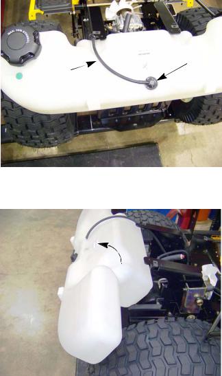
14.Re-install the fuel cap.
15.Disconnect the vent hose from the roll over valve. See Figure 2.11.
Roll over valve
Vent hose
Figure 2.11
Roll out |
16. |
Roll the fuel tank towards the rear of the tractor until it |
|
|
is free from the tractor. See Figure 2.12. |
|
17. |
Disconnect the fuel line from the fuel tank. |
18.Install the fuel tank by following the previous steps in reverse order.
19.Test run the tractor in a safe area before returning it to service.
Figure 2.12
9

2000 Series Tractors
Throttle cable adjustment
If the engine does not achieve its high (no load) speed when the throttle is moved to the full throttle position, check the cable adjustment before performing any other engine or carburetor inspections.
To adjust the throttle cable:
1.Raise the hood and locate the engine control panel.
2.Operate the throttle lever while observing its direction of movement. See Figure 2.13.
3.Loosen the screw that secures the throttle cable clamp.
4.Push and hold the throttle arm at the full throttle position.
5. |
While holding the throttle arm, remove the slack in |
|
|
the cable by pulling the cable jacket back through |
Choke cable |
|
the clamp. |
|
6. |
Tighten the screw in the clamp to secure the cable. |
Throttle cable |
|
|
7.Start the engine.
8. Check the engine RPMs using a tachometer. Figure 2.13
NOTE: Refer to the service manual provided by the engine manufacturer for any further engine speed adjustments needed.
Choke cable adjustment
If the engine is difficult to start or runs roughly after it warms up, check the choke cable setting before performing any other engine or carburetor inspections.
To adjust the choke cable:
1.Remove the air filter.
2.Locate the engine control panel.
3.Loosen the screw that secures the choke cable clamp.
4.Move the choke arm until the choke plate is fully closed.
NOTE: Look down the carburetor throat to confirm that the choke plate is fully closed.
See Figure 2.14.
5.While holding the choke arm, remove the slack in the cable by pulling the cable jacket back through the clamp.
6.Tighten the screw in the clamp to secure the cable.
7.Check the operation of the cable and choke plate.
8.Re-install the air filter.
9.Test run the tractor in a safe area before returning it to service.
Choke plate closed
Figure 2.14
10

Choke and Throttle levers and cables
Control lever assemblies
Figure 2.15
Figure 2.16
Screw
Figure 2.17
Engine Related Parts
To remove/replace levers and cables:
NOTE: The choke and throttle cables must be removed with the lever assemblies before they can be separated and replaced.
1.Remove the dash by following the procedures described in Chapter 4: Body.
2.Remove the three screws that secure the control lever assemblies in place using a 3/8” wrench. See Figure 2.15.
3.Rotate the levers while pulling the assemblies out of the dash.
4.Remove the cables:
4a. Squeeze in the ears on the cable jacket fittings. See Figure 2.16.
4b. Slide the cable jackets out of the bracket.
4c. Un-hook the cables from the levers.
NOTE: If just replacing the cables, install the cables by follow steps 1 - 4 in reverse order.
5.Remove the screw that holds the lever retainer to the bracket using a 5/16” wrench. See Figure 2.17.
11

2000 Series Tractors
6.On the side of the lever assembly that has the slot, lift the shaft that the levers pivot on enough to slide the spring off. See Figure 2.18.
7.Slide the lever assembly toward the side with the slot until the assembly clears the other side.
8.Slide the levers off of the indexing plate. See Figure 2.19.
9.Install the levers and cables by following the previous steps in reverse order.
Spring
Slot
Figure 2.18
Indexing plate
Figure 2.19
12

Engine removal/installation
 Fuel pump
Engine Related Parts
It may be necessary to remove the engine to perform engine repairs such as replacing the ignition coil, flywheel, alternator or to work on the cylinder heads.
To remove the engine:
1.Remove the hood by following the procedures described in Chapter 4: Body.
2.Disconnect the negative battery cable from the battery.
3.Remove the muffler by following the procedures described in the muffler section of this chapter.
4.Clamp off the fuel line just below the fuel pump. See Figure 2.20.
Figure 2.20
5. Disconnect the ground cable from the left side of the engine using a 1/2” wrench. See Figure 2.21.
Oil drain hose
Ground cable
Figure 2.21
|
6. |
Disconnect the PTO clutch harness. |
Engine harness |
7. |
Disconnect the engine harness. |
Starter trigger wire |
8. |
Disconnect the starter wires. See Figure 2.22. |
Starter cable |
9. |
Remove the starter. |
Figure 2.22
13

2000 Series Tractors
10.Remove the dash by following the procedures described in Chapter 4: Body.
11.Disconnect the drive shaft from the engine by removing the four patch bolts using a 7/16” wrench. See Figure 2.23.
Drive shaft 
Figure 2.23
12.Remove the four nuts and bolts, indicated by the arrows in Figure 2.24, that hold the engine to the sub frame using a pair of 9/16” wrenches.
Figure 2.24
13.Attach a lift chain to the engine’s lifting points. See Figure 2.25.
NOTE: The lift chain should be approximately 2’ - 2.5’ (61 - 76 cm) long and is of sufficient strength to safely support weight of the engine.
14.Using an engine hoist, gently lift the engine while sliding it off of the drive shaft and out the front of the tractor.
NOTE: Be careful sliding the engine off of the drive shaft. If the drive shaft coupling gets caught, it will come apart, spilling the blue rollers on the ground.
Lift points 
Figure 2.25
14
Blue rollers

Figure 2.26
Alignment stud 

Figure 2.27
Engine Related Parts
NOTE: If the front drive shaft coupling comes apart:
•Remove the engine.
•Insert the rollers in between the drive shaft end and the coupler housing one at a time, until all eight are in place. See Figure 2.26.
To install the engine:
1.Install an alignment stud into one of the drive shaft coupler holes on the engine. See Figure 2.27.
NOTE: To make an alignment stud: See Figure 2.27.
•Obtain a 1/4” x 20 bolt that is a minimum of 4” long.
•Cut the head off of the bolt.
•Grind a tapper onto the side of the bolt the head was on.
Coupling spacer |
Alignment stud |
|
Coupling
Coupling bolts
Figure 2.28
2.Insert three of the bolts into the coupling and the spacer.
3.Slide the engine into place, using the alignment stud to guide the drive shaft coupler into place.
See Figure 2.28.
4.Start the three coupling bolts.
5.Remove the alignment stud.
6.Install the fourth coupling bolt.
7.Tighten all of the coupling bolts to a torque of 10 - 12 ft lbs (14 - 16 Nm).
15
2000 Series Tractors
8.Install the engine mounting nuts and bolts.
9.Remove the engine lift chain.
10.Install the dash by following the steps described in Chapter 4: Body.
11.Install the starter.
12.Reconnect the starter wires.
13.Reconnect the engine harness.
14.Reconnect the ground cable to the base of the engine.
15.Reconnect the fuel line to the fuel pump.
16.Install the muffler by following the procedures described in the muffler section of this chapter.
17.Install the hood.
18.Check the oil and fuel levels, top off as needed.
19.Test drive the tractor in a safe area before returning it to service.
16

Brakes
CHAPTER 3: BRAKES
Brake adjustment
The transmission on the 2000 series tractor is driven by a Hydro-Gear BDU-10L pump. The pump will provide the braking action when it is in operation. There is a mechanical brake on the side of the transmission. This brake is used primarily as a parking brake. It is also used as a back up brake in case of a failure of the hydro pump.
The operation of the brakes should be tested before performing any adjustments.
By-pass rod 
Figure 3.1
Inner latch plate
Outer latch plate
 travel limit pin
To test the operation of the brakes:
1.Disengage the hydro pump by-pass rod by pulling it out and hooking it. See Figure 3.1.
2.Set the parking brake by depressing the brake pedal and lifting-up on the parking brake lever.
3.Attempt to push the tractor. If it can be pushed by hand without skidding a rear wheel, check and adjust the brakes.
4.Release the parking brake.
5.Attempt to push the tractor again. If it cannot be pushed with reasonable effort, check the hydro pump by-pass and adjust the brakes.
6.Visually inspect the linkage to confirm that it functions properly.
•Beneath the floor panel, on the left side of the tractor there are two semi-circular latch plates (bell cranks).
•The outer latch plate rotates with the drive control pedals. The inner latch plate rotates with the clutch/brake pedal.
6a. With the clutch/brake pedal fully released:
•The travel limit pin should be resting against the front of the curved slot. See Figure 3.2.
Figure 3.2
17
2000 Series Tractors
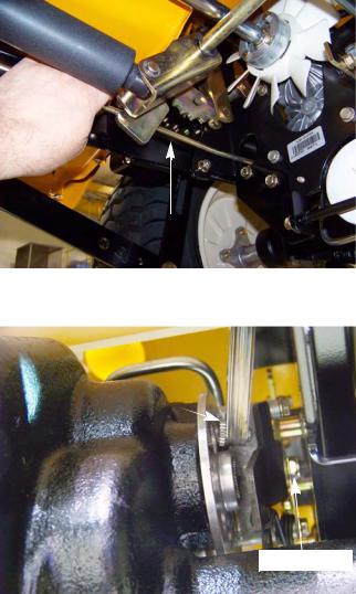
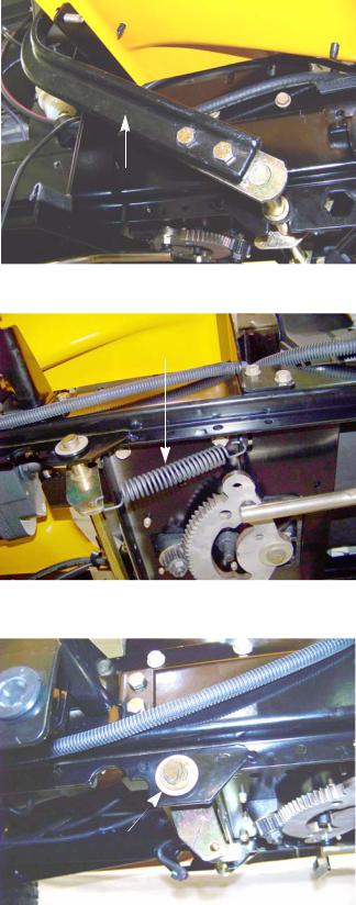
•The rod that connects the clutch/brake latch plate to the heavy brake actuator spring should not droop. See Figure 3.3.
•Check the brake pedal shaft bushings for wear.
Adjust the brakes by:
NOTE: The brake is located between the frame and the transmission on the right side of the tractor. It is a tight fit, but it can be reached from the under side of the tractor aft, of the rear axle.
NOTE: In Figure 3.4, the by-pass rod was removed for a clearer view of the caliper.
1.Wiggle the brake rotor slightly, and attempt to insert a 0.010” (0.38mm) feeler gauge between the rotor and either pad.
NOTE: There is a fixed pad in the transaxle housing.
NOTE: There is a moving pad in the brake caliper.
No droop
Figure 3.3
0.010” feeler gauge
Adjuster nut
Figure 3.4
2.Adjust the gap, if necessary, so that the feeler
gauge slips between the pad and the rotor with light pressure. See Figure 3.4. 2a. Turn the nut to adjust the gap.
NOTE: The gap should be in the range of 0.010” - 0.015” (0.25mm - 0.38mm) 2b. Apply and release the brake pedal, then re-check the gap.
NOTE: If the brake seems to be sticking, or the rotor is discolored from dragging, fix the cause of the sticking and replace the rotor.
3.Re-test the operation of the brakes before returning the tractor to service.
18

Brakes
Brake puck/rotor replacement
On transmission used on the 2000 series tractor, the brake pucks are wearing parts that will need to be serviced from time to time. If the tractor is operated with the parking brake dragging, the pucks will wear out rapidly and the brake rotor will develop hot spots. If the tractor is operated long enough, the rotor may have grinding marks on it with excessively worn pucks.
|
|
|
|
|
|
|
|
If the rotor shows hot spots or any other signs of damage, including warpage, it must be |
|
|
|
! CAUTION |
||
|
|
replaced. Failure to do so can result in the failure of the brakes |
|
|
|
|
|
|
|
|
|
|
|
|
NOTE: The brake pucks and the rotors are serviced at the same time.
|
To remove/replace the brake pucks and rotor: |
|
|
1. |
Lift and safely support the rear of the tractor. |
|
2. |
Remove the transmission by following the proce- |
|
|
dures describe in Chapter 5: Drive. |
Screws |
3. |
Remove the two screws that secure the brake caliper |
|
|
to the right transmission housing using a 3/8” wrench. |
|
|
See Figure 3.5. |
|
4. |
Lift the caliper off of the transmission. |
Figure 3.5
5. Remove the brake disk from the output shaft. See Figure 3.6.
NOTE: The center flange of the brake disk faces outward.
 Flange
Figure 3.6
19

2000 Series Tractors
6.With the caliper on a work bench, remove the brake puck, backing plate and the two brake pins.
See Figure 3.7.
7.Inspect all the components of the brake assembly for damage or wear: brake pads, puck plate, actuator pins, actuator arm, anti-rotation bracket, yoke, torsion spring, flat washer and locking hex nut.
8.Check for free movement of the brake pins. A dry lubricant can be used on the brake pins sparingly.
Never put grease or anti-seize on
! CAUTION brake pins. It can migrate to the brake pucks, preventing the braking action
of the pucks.
9.Slide the brake pins into the caliper.
10.Place the backing plate in the caliper.
11.Place a new puck into the caliper. See Figure 3.8.
NOTE: A piece of scotch tape may be used to hold the new brake pucks in place for assembly. The tape will grind away when the brakes are applied.
12.Place a new brake puck into the recess in the transmission. Use a piece of scotch tape to hold it in place.
13.Slide the brake rotor in place, shoulder out.
14.Mount the brake caliper to the transmission. Apply a small amount of releasable thread locking compound such as Loctite® 242 (blue) to the mounting bolts and tighten to a torque of 80 - 120 in-lbs (9 - 13.5 Nm).
15.Wiggle the brake rotor slightly and insert a 0.010” (0.38mm) feeler gauge between the rotor and either pad.
16.Adjust the gap, if necessary, so that the feeler gauge slips between the pad and the rotor with light pressure. See Figure 3.9.
16a. Turn the nut to adjust the gap.
NOTE: The gap should be in the range of 0.010” - 0.015” (0.25mm - 0.38mm)
16b. Operate the brake cam arm a few times, then re-check the gap.
17.Install the transmission by following the procedures described in Chapter 5: Drive System.
18.Test drive the tractor in a safe area before returning it to service.
Caliper
Pins
 Backing plate
Pucks
Figure 3.7
Figure 3.8
0.010” feeler gauge
Figure 3.9
20
Brake shaft assembly
Brake pedal
Figure 3.10
Brake shaft return spring
Figure 3.11
E-ring
Figure 3.12
Brakes
To remove/replace the brake shaft:
1.Remove the cutting deck by following the procedures described in Chapter 8: Cutting Decks and Lift shaft.
2.Lift and safely support the tractor.
3.Remove the forward drive pedal shaft by following the procedures described in Chapter 5: Drive System.
4.Disconnect the brake pedal by removing the two nuts and bolts that attach it to the brake pedal shaft using a pair of 1/2” wrenches. See Figure 3.10.
5.Disconnect the brake shaft return spring. See Figure 3.11.
6.Remove the E-ring and washer(s) from the right side of the brake shaft. See Figure 3.12.
7.Remove the hex bushings from both ends of the brake pedal shaft.
21
2000 Series Tractors
8.Slide the brake pedal shaft to the left enough for it to clear the frame on the right side.
9.Lower the shaft enough to gain access to the cotter pin that secures the brake rod to the pedal shaft.
10.Remove and discard the cotter pin. See Figure 3.13.
11. Remove the pedal shaft from the tractor. |
Cotter pin |
|
12.Install the brake pedal shaft by following the previous steps in reverse order.
NOTE: The cotter pin that secures the brake rod to
the pedal shaft can be replaced with a bow |
|
tie clip (714-04040). This will make it easier |
Figure 3.13 |
to perform the brake rod adjustment. |
13.Perform a brake rod adjustment by following the
procedures described in the brake rod adjustment section of this chapter.
14.Test drive the tractor in a safe area before returning it to service.
22

Brakes
Brake rod adjustment
NOTE: The brake rod should not come out of adjustment on its own. If the brake rod does need to be adjusted, check for a bent rod, worn bushing and worn brake pucks.
E-ring |
To adjust the brake rod: |
|
1. Remove the cutting deck by following the procedures described in Chapter 8: Cutting Decks and Lift Systems.
2. Lift and safely support the tractor.
3. Remove the E-ring and washers from the right side of the forward drive pedal shaft. See Figure 3.14.
4. Slide the drive pedal shaft to the left until it stops.
Figure 3.14
5. Remove the E-ring and washer(s) from the right side of the brake pedal shaft. See Figure 3.15.
6. Slide the brake pedal shaft to the left until it stops.
 E-ring
Figure 3.15
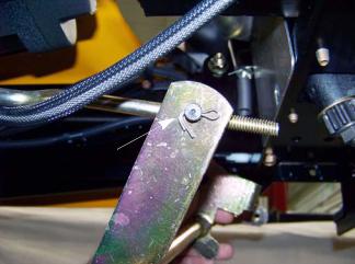
7. Disconnect the brake rod from the brake pedal shaft by removing the cotter pin and discarding it.
See Figure 3.16.
Cotter pin
Figure 3.16
23

2000 Series Tractors
8.Loosen the jam nut. See Figure 3.17.
9.Tighten or loosen the ferrule as needed so that it aligns with the hole in the bell crank of the brake pedal shaft with no slack in the brake spring.
10.Tighten the jam nut.
11.Attach the brake rod to the brake pedal shaft.
NOTE: The cotter pin that secures the brake rod to the pedal shaft can be replaced with a bow tie clip (714-04040).
12.Slide the brake pedal shaft to the right until it stops.
13.Install the E-ring and washer(s) on to the brake pedal shaft.
NOTE: If the bushings popped out while shifting the shafts, re-install them before installing the E-rings.
14.Slide the forward drive pedal shaft to the right until it stops.
15.Install the E-ring and washer(s) on to the drive pedal shaft.
16.Test drive the tractor in a safe area before returning it to service.
Ferrule
Jam nut
Figure 3.17
24
Loading...